


BAUMCUT 26.4
1 2
3
4 5
6
7 8 9
C
0
x
D
PROGRAMMABLE
Original Operating Instructions
BAUMCUT 26.4 PROGRAMMABLE
i
BAUM USA

Index page
Control Panel / Operating Elements ............................................................... E - 4
Explanation of Pictographs on the Display ......................................................E - 5
Chapter Survey ...............................................................................................E - 6
Introduction ..................................................................................................... E - 7
Technical Data/Machine Layout/Transport and Installation ....................K1 - 1
of the Machine/Safety Relevant Machine Elements ......................................K1 - 1
Machine Layout ............................................................................................K1 - 2
Plan .............................................................................................................. K1 - 3
Transport and Installation of the Machine .....................................................K1 - 4
Place of Installation ...................................................................................... K1 - 4
After the Installation of the Machine.............................................................. K1 - 4
Power Supply ............................................................................................... K1 - 5
Type plate .....................................................................................................K1 - 6
Safety Relevant Machine Elements .............................................................. K1 - 7
Accident prevention warning labels at BAUM cutters. ................................... K1 - 8
Safety Relevant Machine Elements .............................................................. K1 - 8
Safety Signs ................................................................................................. K1 - 9
Technical Data ............................................................................................ K1 - 10
Permissible Environmental and Operating Conditions ................................ K1 - 10
Hydraulic Data ............................................................................................ K1 - 10
Safety Precautions ..................................................................................... K1 - 10
Residual Risk ............................................................................................. K1 - 10
Technical Data ............................................................................................ K1 - 11
Safety ........................................................................................................... K2 - 1
Start Up ....................................................................................................... K3 - 1
Switching Machine ON ................................................................................. K3 - 2
Turning Machine OFF ................................................................................... K3 - 2
Measurement Display and Measurement System ........................................ K3 - 3
Manual Operation .......................................................................................K4 - 1
Cutting Line Indicator, Mechanical with Clamp.............................................. K4 - 2
Cutting Line Indicator, Optical .......................................................................K4 - 2
Setting of Measurements (Backgauge Movement) by Hand ......................... K4 - 2
Clamp Pressure Adjustment ......................................................................... K4 - 3
Setting the Clamping Time ........................................................................... K4 - 3
Clamping and Cutting ................................................................................... K4 - 3
Light Barrier ..................................................................................................K4 - 4
Continuation: Light Barrier ............................................................................ K4 - 5
Clamping with False Clamp Plate ................................................................. K4 - 6
Automatic Operation ............................................................................... K5A - 1
Introduction ................................................................................................. K5A - 2
Basic Displays ............................................................................................ K5A - 3
Basic Display: Program Data ......................................................................K5A - 3
Contin.: Basic Display: Program Data ......................................................... K5A - 4
Basic Display: Program Information ........................................................... K5A - 5
Basic Display: Program Directory ............................................................... K5A - 6
Basic Display: Main Menu (Function Survey) .............................................. K5A - 7
Menu "Help":............................................................................................... K5A - 7
Explanation of pictographs .........................................................................K5A - 7
Cursor Movement in Basic Display .............................................................K5A - 8
Automatic Backgauge Adjustment through Numerical Keyboard ................ K5A - 9
Deletion of a Wrong Input .........................................................................K5A - 10
Moving Backgauge to a Nominal Position (Positioning) ............................K5A - 10
Input Error: Value of Nom. Backgauge Position too Low/High ..................K5A - 10
Selection of a Free Program/Display of the Next Free Program ............... K5A - 11
Selecting a Program .................................................................................K5A - 12
Continuing: Selecting a Program .............................................................. K5A - 13
Storage of Measurements ........................................................................ K5A - 14
Setting Up a Cutting Program, Example 1 ................................................ K5A - 15
Setting Up a Cutting Program, Example 2 ................................................ K5A - 16
Correction of an Input Error ...................................................................... K5A - 17
Automatic ON/OFF ...................................................................................K5A - 18
Running a Cutting Program ...................................................................... K5A - 19
Storing of Program Informations ............................................................... K5A - 20
Deletion of a Step Number........................................................................ K5A - 21
Deletion of One/Several Program(s) ......................................................... K5A - 22
Deletion of Complete Memory .................................................................. K5A - 23
Inserting of Measurements into a Program ...............................................K5A - 24
Storing of Measurements According to Printed Image ..............................K5A - 24
Calculator Functions .................................................................................K5A - 25
Negative Sign ...........................................................................................K5A - 26
Using Backgauge Position of Calculations ............................................... K5A - 26
Machine Functions and Additional Functions (Menu Keys) ................ K5B - 1
Machine Function: Main Menu (Function Survey) ...................................... K5B - 2
Menu "Help":.............................................................................................. K5B - 2
Explanation of pictographs ........................................................................ K5B - 2
Service ...................................................................................................... K5B - 3
E - 2

Index
Select Language/Measuring Unit ............................................................... K5B - 3
Knife Compensation ................................................................................. K5B - 4
Resting Time for Knife at BDC................................................................... K5B - 5
Maintenance Cut Counter .......................................................................... K5B - 6
Preset Functions ....................................................................................... K5B - 7
Continuing: Preset Functions ..................................................................... K5B - 8
Adjustment of Display Contrast ................................................................. K5B - 9
Block Programming ................................................................................. K5B - 10
Variation 2................................................................................................ K5B - 10
(with edge trim preadjusting) ................................................................... K5B - 10
Variation 1................................................................................................ K5B - 10
Variation 3................................................................................................ K5B - 10
Attention! ................................................................................................. K5B - 12
Function "Help":Explanation of pictographs and description of functions . K5B - 12
Four trim cut ............................................................................................ K5B - 13
Four trim cut with labels ........................................................................... K5B - 14
Menu Key: Additional Functions ............................................................ K5C - 1
Storage of Additional Functions with Cut Size ............................................ K5C - 2
Subsequent Storing of Additional Functions............................................... K5C - 2
List of Additional Functions ........................................................................ K5C - 3
Menu Key: Auxiliary Functions .............................................................. K5D - 1
Cut and Record ......................................................................................... K5D - 2
Sheet Size Tables ...................................................................................... K5D - 2
Subtraction Repetition Unit ........................................................................ K5D - 3
Graphics OFF ............................................................................................ K5D - 3
Maintenance ................................................................................................ K8 - 1
Basic information about servicing and maintenance work ............................ K8 - 2
Menu Key: Machine Parameters ............................................................ K5E - 1
Prepressure Time ...................................................................................... K5E - 2
Resting time for knife at BDC .................................................................... K5E - 2
Knife Change .............................................................................................. K6 - 1
Knife change ................................................................................................ K6 - 2
Changing of cutting stick .............................................................................. K6 - 5
Malfunctions/Breakdowns .........................................................................K7 - 1
Electrical Malfunctions/Breakdowns ............................................................. K7 - 2
Start - Up Breakdown: Scan Reference Point/Auxiliary Mode ....................... K7 - 3
Mechanical Breakdown:Rupture of a Knife Bar/Clamp Recuperating Spring K7 - 4
E - 3
1 2
3
4 5
6
7 8 9
C
0
x
D
PROGRAMMABLE
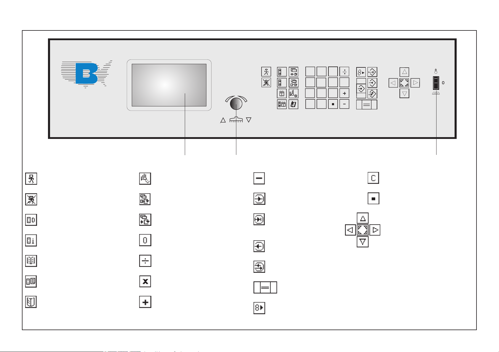
Control Panel / Operating Elements
i
21 3
Automatic ON
Automatic OFF
Program Data
Program Information
Function Survey (Main Menu)
Program Directory
Program Selection
E - 4
Machine Parameter
Auxiliary Program Functions
Additional Functions
Numerical keyboard
Division
Multiplication
Addition
Subtraction
Enter
Insert; subsequent insertion of
data
Delete
Correction (of stored data)
Equal key
Transfer key: Transfer backgauge
pos. into input field
Clear input field
Decimal point
Cursor
(4 keys: right, left, up, down;
Center key: Additional cursor
motion; cursor in basic position
1 Display
2 Turning knob for backgauge move-
ment
(Electronic hand wheel)
3 Switch for optical cutting line
indicator and table light ON
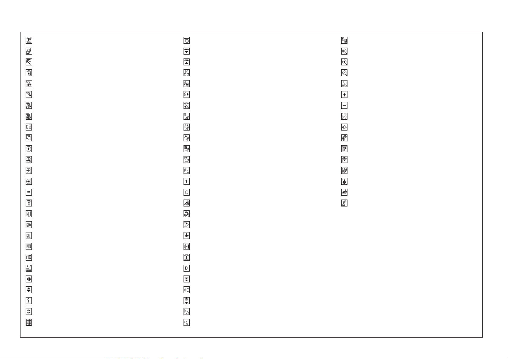
Explanation of Pictographs on the Display
Pre clamping time
Clamping force grade
Feed mark
Programmable ejector
External special functions
Program functions
Program parameters
Various auxiliary functions
Free program
Paper sizes
Enter
Correction
Delete
Insert
Key Equal
Key Positioning (2x Ist-Gleich)
Program selection
Hand wheel/electr. hand wheel
Sensor key forward
Sensor key reverse
Cut buttons
Marking during cutting
Actual to nominal position
Automatical ejector off
Function survey/Memory
function survey/Language
Function survey/Service
Function survey/Block programming
Function survey/preset functions
Machine parameters
Number (1 - 0)
Clear/Clear input
Service
Call sevice
Order
Look for order
Select program number
Delete program number
Under cut
Plus/positive sign
Minus/negative sign
Change contrast of display
Spare cursor
Original sheet size/Block programming
Label size/Block programming
Edge trim/Block programming
( - ) Subtraction repetition unit
Grafics off
Block programming
Knife/Lower dead point time
Program data display
Program information
Function survey
Program directory
Nominal position
Key Cursor right/left
Key Cursor up/down
Help
Key Cursor Home
Numerical keyboard
Error
Reference run
Correct basic position
Correct actual position
German (Language)
Please wait
Clear/Exit
Spare cursor
Main drive unit not ready
Press pedal
E - 5

Chapter Survey
Chapter Survey Page
1.0 Technical Data/Machine Layout/Transport and Installation of Machine/
Safety Relevant Machine Elements ................................................................................ K1 - 1
2.0 Safety.............................................................................................................................. K2 - 1
3.0 Start Up........................................................................................................................... K3 - 1
4.0 Manual Operation ........................................................................................................... K4 - 1
5.0 Automatic Operation .................................................................................................... K5A - 1
E - 6
6.0 Knife Change .................................................................................................................. K6 - 1
7.0 Malfunctions/Breakdowns ............................................................................................... K7 - 1
8.0 Maintenance ................................................................................................................... K8 - 1

Introduction
BAUM cutting machines form a part of the wide range of products manufactured by the BAUM company.
Decades of experience in constructing high speed cutting machines and peripheral equipment, together with state-of-the-art engineering and manufacturing procedures,
careful testing and highest quality standards ensure the reliability and performance of your BAUM machine.
Please pay special attention to the following information:
• The section on “Safety” in the operating instructions!
• The operating instructions are not meant as an instruction for repair. Such work should be carried out by BAUM service, exclusively.
• Use only original BAUM spare parts; indicate type and machine number in your requests.
• Illustrations in the operating instructions/spare parts catalogue may deviate from the real design. Nevertheless, the information given is not altered by this.
• The use of the aids mentioned in the operting instructions, such as oils, greases, cleansing agents etc. refers to the preparation date of these instructions.
The complete Technical Documentation should always be kept near the machine.
We recommend to read these operating instructions carefully prior to commissioning the machine, because we shall not be liable for any damage or breakdown resulting
from any nonobservance of these operating instructions.
Copyright
All rights reserved for this document. No part of it may be duplicated or brought to the notice of other people in any form without our express consent.
Any violation engages to damages.
The Operating Instructions must be stored for future use!
E - 7

E - 8

1.0
Technical Data / Machine Layout / Transport and Installation
of the Machine / Safety Relevant Machine Elements
K1 - 1
1 2
3
4 5
6
7 8 9
C
0
x
D
PROGRAMMABLE
1.0 Technical Data/Machine Layout/Transport and Installation of the Machine/Safety Relevant Machine Elements
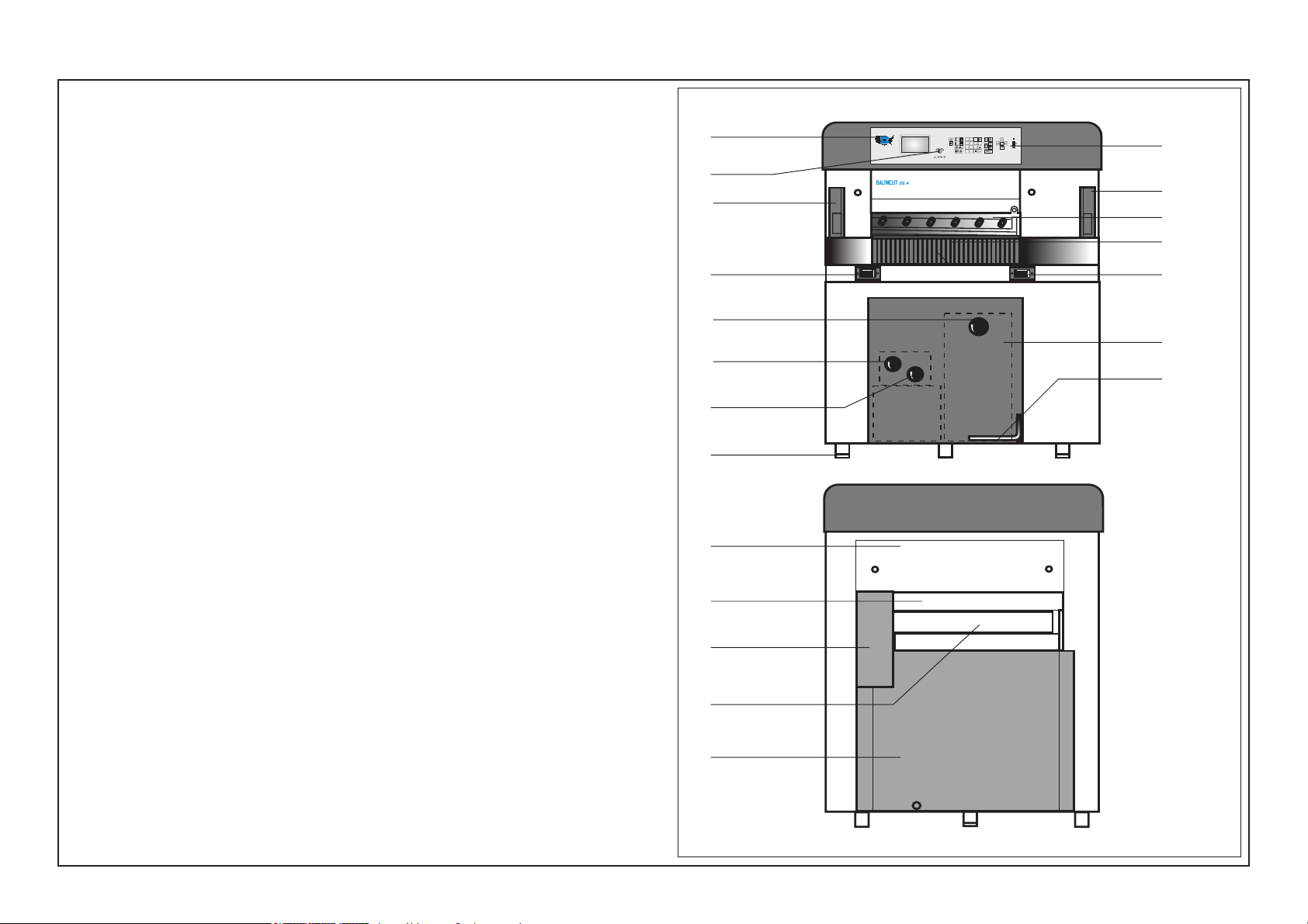
Machine Layout
Front side (operating side)
2
1 Main switch
2 Control panel with display
3 Electronic hand wheel / fine adjustment of cut size
4 Cut buttons
5 Clamping pressure adjustment
3
12
4
i
7
12
6
9
4
6 Clamp and knife bar with knife
7 Switch for cutting line indicator/ Table lamp
8 Backgauge with rakes
9 Cutting stick / Cutting line
10 Pedal
11 Protective guard for backgauge drive
12 Light barrier with guard
13 Guards - front side
14 Guards - rear side
15 Guard - rear table
16 Guard to prevent reaching under the clamp bar
17 Foot
18 Turning knob for knife change
1
13
18
10
5
17
Rear side
16
15
11
8
14
K1 - 2
1.0 Technical Data/Machine Layout/Transport and Installation of the Machine/Safety Relevant Machine Elements
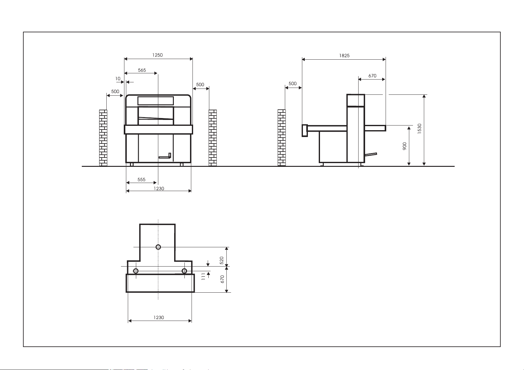
Plan
Dimensions in mm!
K1 - 3

1.0 Technical Data/Machine Layout/Transport and Installation of the Machine/Safety Relevant Machine Elements
Transport and Installation of the Machine
After Unloading
• Remove all packing and wrapping material
• Check machine and accessories for damages
• Check for missing parts
Have the machine installed by BAUM service personnel, exclusively!
The installation of the machine requires special skills which can be
guaranteed only by especially trained experts of BAUM agencies.
Arbitrary working on the machine may damage the machine itself or other
material property of the user or cause accident endangering life and limb
of the staff.
The machine must be unpacked, moved, transferred and installed by
authorized BAUM Service Technicians only. Dangers might arise from the
machine itself or from its packing if it is unpacked, moved, transferred or
installed with unsuitable devices.
While the machine is unpacked, moved, transferred and installed, no
other persons must be present in the range of the machine or its packing.
The BAUM Service Technician must also take care that no unauthorized
persons work at the machine, its packing or the installation equipment.
In Case of Complaints
Immediately send written note to:
• Railway or shipping company
• Insurance company
• BAUM / Agency
Place of Installation
The location must meet the following requirements:
• Vibration free location
• Even concrete flooring, concrete property class min. (N/mm²) according to
eurocode 2: C20/25 or according to DIN1045: B 25.
• Observe carrying capacity!
• Avoid possible accidents of operator by uneven flooring
• Adhere to minimum distance from buildings or peripheral equipment (see
plan)
After the Installation of the Machine
K1 - 4
1. Remove anti rust paint (agent: kerosene, gasoline) from the machine on
the site of installation
Note:
Do not use any sharp tools to remove anti-rust paint!
2. Clean plastic covers only with plastic cleansing agent
3. Final check according to check list
4. Have handover signed
1 2
3
4 5
6
7 8 9
C
0
x
D
PROGRAMMABLE
1.0 Technical Data/Machine Layout/Transport and Installation of the Machine/Safety Relevant Machine Elements
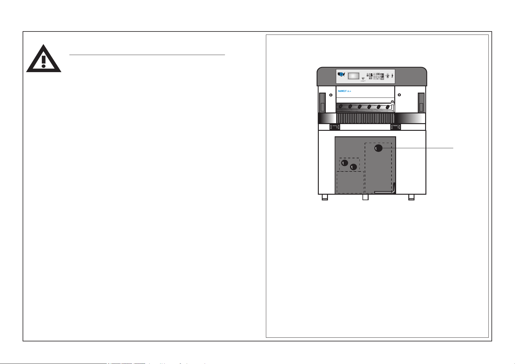
Power Supply
The machine is to be connected by an authorized electrician, only!
Connect machine according to diagram!
• When the system is operated with residual current breaker, use a residual current breaker ( > 30 mA ) for each machine!
• All the cables marked with a symbol, as well as any cables with
orange sheath are still alive even if the main switch has been shut off.
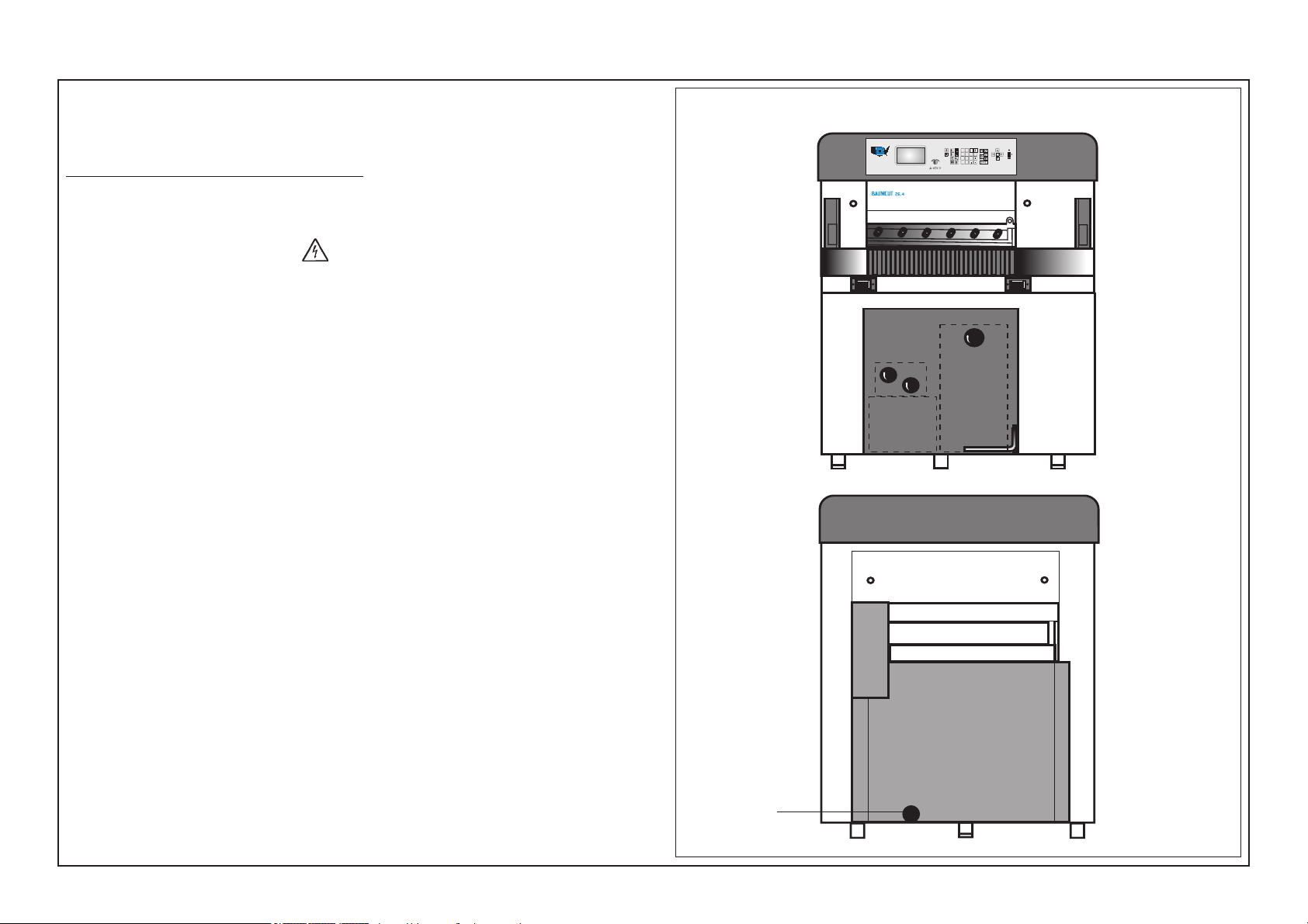
Energy supply is made from the rear of the machine.
Power supply is located within the connection box; access via front guard.
Front side (Operating side)
i
Rear side
Energy
lead wire
K1 - 5
1.0 Technical Data/Machine Layout/Transport and Installation of the Machine/Safety Relevant Machine Elements
Type Plates
Type plate
The machine designation including
• manufacturer‘s address
• model
• machine number
• date of fabrication
• electric. equipment
is indicated on the machine type plate.
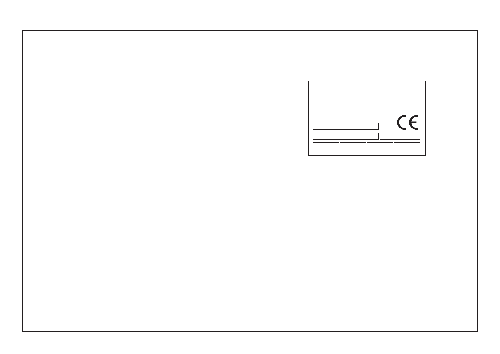
Type plate
Model
Serial No.
/PE AC
Adolf Mohr
Maschinenfabrik
65719 Hofheim/Ts
Germany
mfd.
V
Hz
A
K1 - 6
1 2
3
4 5
6
7 8 9
C
0
x
D
PROGRAMMABLE
1.0 Technical Data/Machine Layout/Transport and Installation of Machine/Safety Relevant Machine Elements
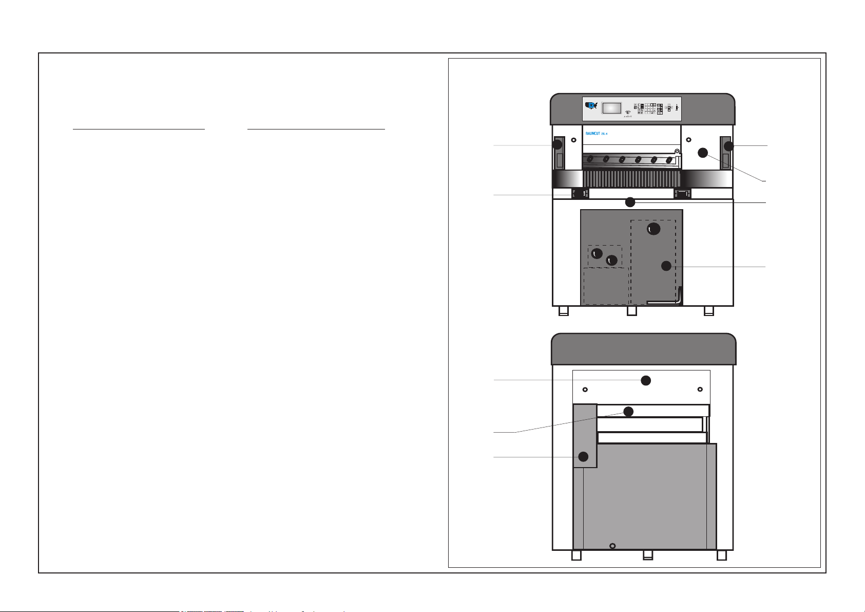
Safety Relevant Machine Elements
1 Main switch
2 Light barrier (20 - channel)
Capacity to recognize object: 25 mm
Min. distance of light barrier: Total reaction time of system:
328 mm < 120 ms
3 Knife bar spring assembly (mechanical lock against lowering of knife
bar)
4 Clamping bar spring assembly (mechanical lock against lowering of
clamping bar)
5 Two-handed cutting release with simultaneity control and anti-repeat
circuit
6 Electronics:
- Failsafe control by multiple self-diagnostics
- Machine self-diagnostics with error message
7 Guard to prevent reaching under the clamp bar
8 Rear-table guard
Front side (operating side)
2
5
Rear side
i
2
3
4
6
9 Guard of backgauge drive unit
Safety Auxiliary Tools
Angle for jogging the cutting material
Knife protection for knife change
Working Area of Operating Personnel
Working area is the complete front side (operating side) of the machine.
7
8
9
K1 - 7
1.0 Technical Data/Machine Layout/Transport and Installation of the Machine/Safety Relevant Machine Elements
Safety Relevant Machine Elements
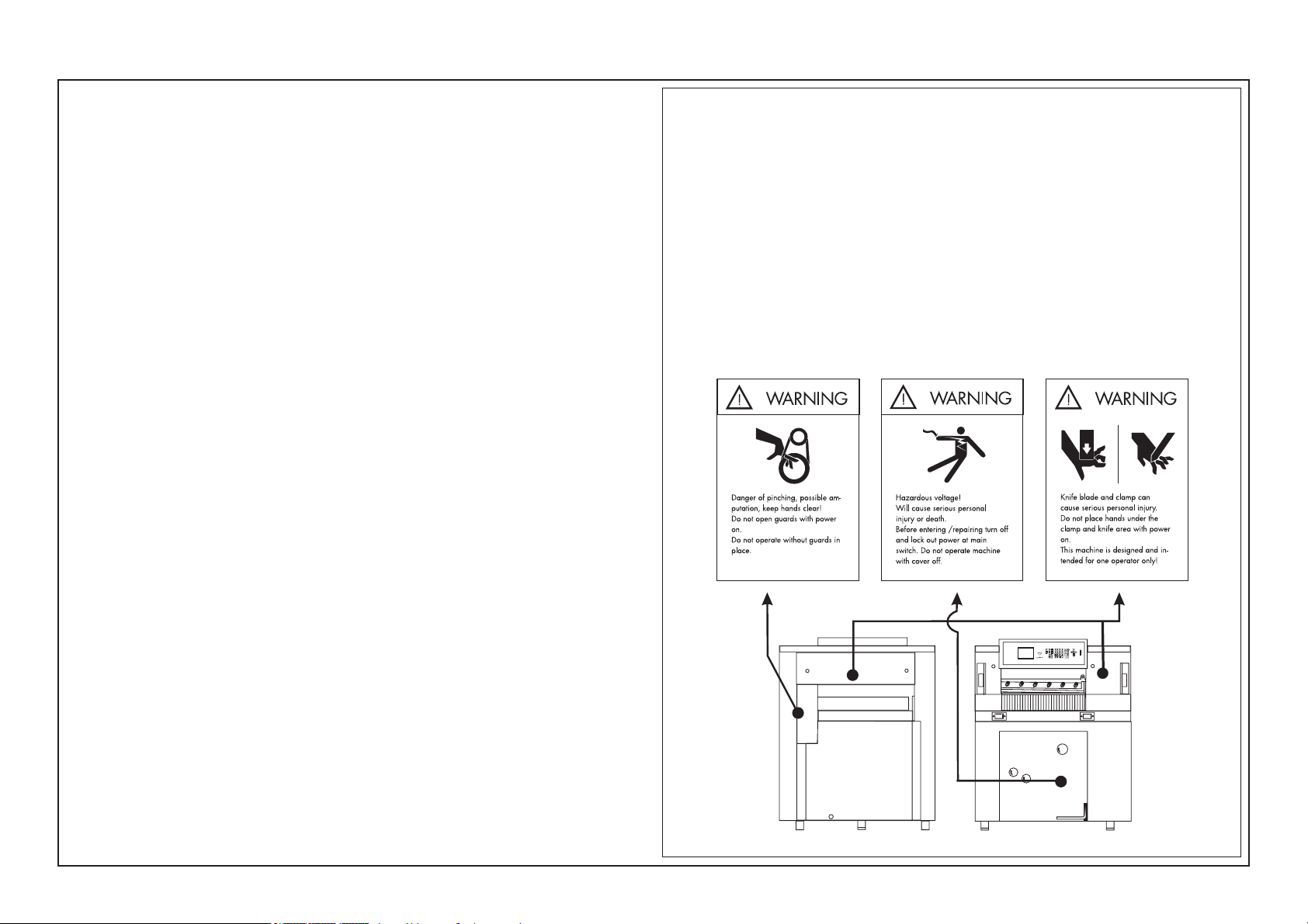
Accident prevention warning labels at BAUM cutters.
Placement of the warning label
Warning labels are of little value if the foreseeable user cannot see them at
the appropriate time, i.e., before he or she encounters the hazard. Labels,
therefore, should be placed near the hazard and in such a position that the
worker will see and be able to read them before encountering the hazard.
Durability
Accident prevention warning labels should be kept sufficiently durable to
remain easily readable at an appropriate distance for a reasonable life.
Placement of the warning labels
Label 1 (1x):
Location:
At backgauge drive
guard.
BAUM order no.:
281267
Label 2 (1x):
Location:
At the lower front of the
cutter.
BAUM order no.:
281266
Label 3 (2x):
Location:
At the front and the rear
of the cutter.
BAUM order no.:
281268
K1 - 8

Safety Signs
Safety Signs / Warning Signs
In order to ensure maximum safety the machine / system is provided with safety
signs. Safety signs are either standardized safety signs warning of risks or
danger, or warning signs alerting the operating or service staff of
- any forbidden actions at the machine / system,
and/or
- informing about any load limits, such as the max. carrying capacity of the
machine and/or its load carrying unit.
Safety signs must be durable and have to be kept in a perfectly visible condition.
Warning signs ought to be visible in good time even from a great distance.
The machine /system may be provided with the following safety or warning
signs on various components of the machine:
Warning: Dangerous voltage
(e. g. electrical connector boxes, control boxes/control
cabinets of machine control systems)
K1 - 9

1.0 Technical Data/Machine Layout/Transport and Installation of Machine/Safety Relevant Machine Elements
Technical Data
Permissible Environmental and Operating Conditions
Operate the machine in closed areas, exclusively!
Air humidity: 35% - 95% (non condensing)
Ambient air temperature: +5°C - +40°C
Hydraulic Data
Hydraulic pressure, max.: 160 bars!
Safety Precautions
• Minimum age of operating staff: 18 years!
• Before starting any work at the machine - read safety section of manual!
• During the working process no other persons must enter the working area or
interfere with the process
• Use the angle included in the scope of supply for positioning the cutting
material
• Observe the procedures described in case of malfunctions and the mainte
nance intervals indicated.
Residual Risk
In spite of the safety measures provided by construction there remains a
residual risk when operating the machine.
This residual risk mainly concerns the danger of contusions and cuts during
clamping, cutting or knife change as well as handling the cutting material in
general, if the necessary care is neglected.
The parts especially affected are the upper extremities of the operating staff especially their arms and hands.
Special care must be taken when performing the knife change. It may only be
carried out by personnel especially trained for this job!
During knife change no other persons must enter the working area of the
machine (cuts)!
• Knife change may only be carried out by personnel especially trained for this
purpose
• Utmost care must be taken when handling the knife!! Always deposit or
transport the knife in the knife case.
• Use only undamaged and sharp knives!
• During the cutting no tool or objects - such as e.g. T-wrench must be on the
machine table in order to prevent them from reaching unintentionally under
the clamp and/or knife during the cutting process. There is a high risk of
injuries due to little parts of the knife edge coming off in splinters.
K1 - 10

1.0 Technical Data/Machine Layout/Transport and Installation of the Machine/Safety Relevant Machine Elements
Technical Data
Cutting width 67 cm / 26,38"
Clamp opening 8 cm / 3,15"
Feed depth 67 cm / 26,38"
Power requirement (main motor):
Single phase A C 2,2 kW / 3,1 H.P.
3 phase 2,4 kW / 3,4 H.P.
Net weight 620 kg / 1367 lbs
Width 125 cm / 49,2"
Length 182,5 cm / 71,85"
Height 151,5 cm / 59,64"
Front table length 67 cm / 26,38"
Table height 90 cm / 35,43"
Clamp pressure, min. 200 daN / 440 lbs
max. 1500 daN / 3300 lbs
Voltage supply (3 phase) 200 - 240, 50/60Hz
Fusing 3 x 25A
Voltage supply (3 phase) 360 - 420V, 50/60Hz
Fusing 3 x 16A
Voltage supply single phase AC (200 - 240, 50Hz)
Fusing 1 x 32A
Voltage supply single phase AC (210 - 240, 60Hz)
Fusing 1 x 32A
Attention!
The wire cross section of the main power supply according to the countrys regulations.
Same regulations according the plug connectors.
Knife thickness 9,7 mm / 0,38"
Grinding reserve, max. 2,2 cm / 0,86"
Smallest cut
without false clamp, min. 1,5 cm / 0,6"
with false clamp, min. 5 cm / 1,96"
Backgauge speed 0 - 7 cm/sek.
Knife speed/min.20
daN = kp
Noise emission
Metering of noise level according to DIN EN 13023, LpA (dB):
76,5 with 300 cuts/hour (manual feeding)
79,5 with 600 cuts/hour (manual feeding)
Extraneous and room noise correction has been carried out.
K1 - 11

K1 - 12
2.0
Safety
Any person on the user´s premises concerned with
the operation, maintenance and repair of the machine, resp., is expected to have read and comprehended the section on "Safety"
K2 - 1

Foreword to the operating instructions
These operating instructions are designed to familiarize the
user with the machine/plant and its designated use.
The instruction manual contains inportant information on
how to operate the machine/plant safely, properly and most
efficiently. Observing these instructions helps to avoid
danger, to reduce repair costs and downtimes and to
increase the reliability and life of the machine/plant.
The instruction manual is to be supplemented by the
respective national rules and regulations for accident
prevention and environmental protection.
The operating instructions must always be available wherever the machine/plant is in use.
These operating instructions must be read and applied by
any persons in charge of carrying out work with and on the
machine/plant such as
- operation including setting up, troubleshooting in the
course of work, evacuation of production waste, care and
disposal of fuels and consumables.
- maintenance (servicing, inspection, repair) and/or
- Transport
In addition to the operating instructions and to the mandatory rules and regulations for accident prevention and environmental protection in the country and place of use of the
machine/plant, the generally recognized technical rules for
safe and proper working must also be observed.
Fundamental safety instructions
Warning and symbols
The following signs and designations are used in the manual
to designate instructions of particular importance
Note/Attention: refers to special information on
how to use the machine/plant
most efficiently
Symbol: refers to orders and prohibitions
designed prevent injury or
extensive damage
Basic operation and designated use of the machine/
plant
The machine/plant has been built in accordance with stateof-the-art standards and the recognized safety rules.
Nevertheless, its use may constitute a risk to life and limb of
the user or of third parties, or cause damage to the machine
and to other material property.
The machine/plant must only be used in technically perfect
condition in accordance with its designated use and the
instructions set out in the operating manual, and only by
safety-conscious persons who are fully aware of the risks
involved in operating the machine/plant. Any functional
disorders, especially those affecting the safety of the
machine/plant, should therefore be rectified immediately.
The machine is meant exclusively for cutting leaved
materials, such as paper, cardboard or plastic films.
Any other use, such as the cutting of harder, especially thicker
materials and materials of other kinds, as well as any further
use beyond this, is considered as not being in accordance
with the designated use. Such materials may be processed
only according to prior agreement with the manufacturer of this
machine and after a written confirmation by the manufacturer.
The manufacturer/supplier cannot be held liable for any
damage resulting from such use. The risk of such misuse lies
entirely with the user.
Operating the machine within the limits of its designated use
also involves the instructions set out in the operating manual
and complying with the inspection and maintenance directives.
Organizational measures
The operating instructions must always be at hand at the
place of use of the machine/plant.
In addition to the operating instructions, observe and instruct
the user in all other generally applicable legal and other
mandatory regulations relevant to accident prevention and
environmental protection.
These compulsory regulations may also deal with the
handling of hazardous substances, issuing and/or wearing
of personal protective equipment, or traffic regulations.
The operating instructions must be supplemented by
instructions covering the duties involved in supervising and
notifying, special organizational features, such as job
organization, working sequences or the personnel entrusted
with the work.
Personnel entrusted with work on the machine must have
read the operating instructions and in particular the chapter
on safety before beginning work. Reading the instructions
after work has begun is too late. This applies especially to
persons working only ocassionally on the machine, e. g.
during setting up or maintenance.
Check - at least from time to time - whether the personnel is
carrying out the work in compliance with the operating
instructions and paying attention to risks and safety factors.
For reasons of security, long hair must be tied back or
otherwise secured, garments must be close-fitting and no
jewellery - such as rings - may be worn. Injury may result
from being caught up in the machinery or from rings
catching on moving parts.
Use protective wherever required by equipment by the
circumstances or by law.
K2 - 2

Observe all safety instructions and warnings attached to the
machine/plant.
See to it that safety instructions and warnings attached to the
machine are always complete and perfectly legible.
In the event of safety-relevant modifications or changes in the
behaviour of the machine/plant during operation, stop the
machine/plant immediately and report the malfunction to the
competent authority/person.
Never make any modifications, additions or conversions which
might affect safety without the supplier´s approval. This also
applies to the installation and adjustment of safety devices and
valves as well as to welding work on load-bearing elements.
Spare parts must comply with then technical requirements
specified by the manufacturer. Spare parts from original
equipment manufacturers can be relied to do so.
to safety.
Do not allow persons to be trained or instructed or persons
taking part in a general training course to work on or with the
machine/plant without being permanently supervised by an
experienced person.
Work on the electrical system and equipment of the machine/
plant must be carried out only by a skilled electrician or by
instructed persons under the supervision and guidance of a
skilled electrician and in accordance with electrical engineering rules and regulations.
Work on the hydraulic system must be carried out only by
personnel with special knowledge and experience of hydraulic
equipment.
Safety instructions governing specific operational
phases
Special work in conjunction with utilization of the machine/plant and maintenance and repairs during operation;
disposal of parts and consumables
Observe the adjusting , maintenance and inspection activities
and intervals set out in the operating instructions, including
information on the replacement of parts and equipment. These
activities may be executed by skilled personnel only.
Brief operating personnel before beginning special operations
and maintenance work, and appoint a person to supervise the
activities.
In any work concerning the operation, conversion or adjustment of the machine and its safety-oriented devices or any
work related to maintenance, inspection and repair, always
observe the start-up and shut-down procedures set out in the
operating instructions and the information on maintenance
work.
Never modify the software of programmable control systems.
Replace hydraulic hoses within stipulated and appropriate
intervals even if no safety-relevant defects have been detected.
Adhere to prescribed intervals or those specified in the
operating instructions for routine checks and inspections.
Selection and qualification of personnel - Basic responsibilities
Any work on and with the machine/plant must be executed by
reliable personnel only. Statutory minimum age limits must be
observed.
Employ only trained or instructed staff and set out clearly the
individual responsibilities of the personnel for operation, setup, maintenance and repair.
Make sure that only authorized personnel works on or with the
machine.
Define the machine operator´s responsibilities - also with
regard to observing traffic regulations - giving the operator the
authority to refuse instructions by third parties that are contrary
Standard operation
Avoid any operational mode that might prejudicial to safety.
Take the necessary precautions to ensure that the machine is
used only when in a safe and reliable state.
Operative machine only if all protective and safety-oriented
devices, such as removable safety devices, emergency shutoff equipment, sound-proofing elements and exhausters, are
in place and fully functional.
Check the machine/plant at least once per working shift for
obvious damage and defects. Report any changes (incl.
changes in the machine´s working behaviour) to the competent organization/person immediately. If necessary, stop the
machine immediately and lock it.
In the event of malfunctions, stop the machine/plant immediately and lock it. Have any defects rectified immediately.
During start-up and shut-down procedures always watch the
indicators in accordance with the operating instructions.
Before starting up or setting the machine/plant in motion,
make sure that nobody is at risk.
Never switch off or remove suction and ventilation devices
when the machine is in operation.
Ensure that the maintenance area is adequately secured.
If the machine/plant is completely shut-down for maintenance
and repair work, it must be secured against inadvertent
starting by:
- locking the principal control elements and removing the
ignition key and/or
- attaching a warning sign to the main switch.
Clean the machine, especially connections and threaded
unions, of any traces of oil or presevatives before carrying out
maintenance/repair. Never use aggressive detergents. Use
lint-free cleaning rags.
Always tighten any screwed connections that have been
loosened during maintenance and repair.
Any safety devices removed for set-up, maintenance or repair
purposes must be refitted and checked immediately upon
completion of the maintenance and repair work.
Ensure that all consumables and replaced parts are disposed
of safely and with minimum environmental impact.
K2 - 3

Warning of special dangers
Any procedure impairing the safety at the machine must be
refrained from. In particular do not
The electrical equipment of machines/plants is to be inspected and checked at regular intervals. Defects such as loose
connections or scorched cables must be rectified immediately.
leaks and obvious damage. Repair damage immediately.
Splashed oil may cause injury and fire.
Depressurize all systems sections and pressure pipes
(hydraulic system, compressed-air
system.
- reach into the range of knife and clamp, use auxiliary
tools (e. g. material gauge)
- reach into the range between clamp and cutting material
gauge (backgauge with rake) on the machine rear table
- with Autotrim function:
entering the opened table crack to remove residual cuttings.
Only do that with the machine switched off.
- at machines with attached and/or separately installed
peripheral equipment with lifting/swivelling/moving and/or
clamping function:
do not enter or reach into the danger zone during movement
(provide guard rail)
- The knife may only be changed by personnel especially
instructed for this purpose
Electrical energy
Use only original fuses with the specified current rating.
Switch off the machine/plant immediately if trouble occurs in
the electrical system.
Work on the electrical system or equipment may only be
carried out by a skilled electrician himself or by specially
instructed personnel under the control and supervision of
such electrician and in accordance with the applicable
electrical engineering rules.
If provided for in the regulations, the power supply to parts
of machines and plants, on which inspection, maintenance
and repair work is to be carried out must be cut off. Before
starting any work, check the de-energized parts for the
presence of power and ground or short-circuit them in
addition to insulating adjacent live parts and elements.
Necessary work on live parts and elements must be carried
out only in the presence of a second person who can cut off
the power supply in case of danger by actuating the emergency shut-off or main power switch. Secure the working
area with a red-and-white safety chain and a warning sign.
Use insulated tools only.
Before starting work on high-voltage assemblies and after
cutting out the power supply, the feeder cable must be
grounded and components, such as capacitors, shortcircuited with a grounding rod.
Gas, dust, steam and smoke
Carry out welding , flame-cutting and grinding work on the
machine/plant only if this has been expressly authorized, as
there may be a risk of explosion and fire.
Before carrying out welding, flame-cutting and grinding
operations, clean the machine/plant and its surroundings
from dust and other inflammable substances and make sure
that the premises are adequately ventilated (risk of explosion).
Observe any existing national regulations if work is to be
carried out in narrow rooms.
Hydraulic and pneumatic equipment
Work on hydraulic equipment may be carried out only by
persons having special knowledge and experience in
hydraulic systems.
The pneumatic equipment at the machine must only be
connected to plant compressed-air supply system secured
against overpressure.
Hydraulic and compressed-air lines must be laid and fitted
properly. Ensure that no connections are interchanged. The
fittings, lenghts and quality of the hoses must comply with
the technical requirements.
Oil, grease and other chemical substances
When handling oil, grease and other chemical substances,
observe the product-related safety regulations.
Be careful when handling hot consumables (risk of burning
or scalding)
K2 - 4
Check all lines, hoses and screwed connections regularly for
3.0
Start Up
Attention!
Prior to any commissioning and any change of shifts the operating staff
has to check if the safety-related machine elements are in proper service
condition and complete.
K3 - 1
1 2
3
4 5
6
7 8 9
C
0
x
D
PROGRAMMABLE
3.0 Start Up
Switching Machine ON
Attention!
Prior to any commissioning and any change of shifts
the operating staff has to check if the safety related
machine elements are in proper service condition and
complete.
1. Turn main switch (2) from "0" to "I"
< Control voltage is switched on.
After several seconds display shows Program data display >
i
Turning Machine OFF
1. Wait until automatic operations have ended.
2. Turn main switch from " I " to "0" position
to prevent a start-up of the machine:
Place padlock into main switch, lock it and remove the key.
2
K3 - 2
3.0 Start Up
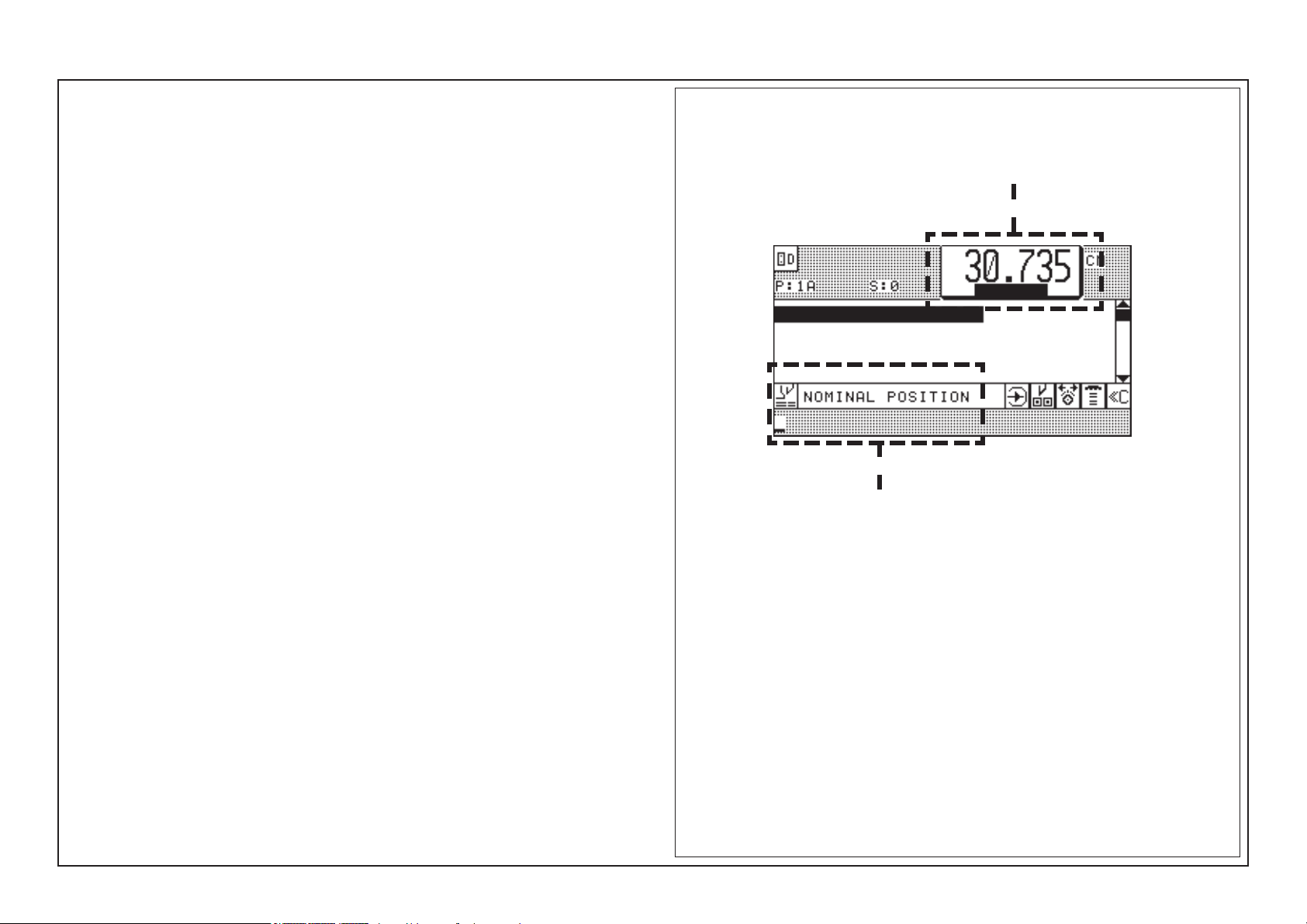
Measurement Display and Measurement System
It shows among other things...
on the upper screen (A): ACTUAL POSITION
on the lower screen (Nominal position input field, B):
NOMINAL POSITION INPUT
The actual position (A) shows the real backgauge position in mm, cm, inches or
sun = 1/10 shaku (Japan).
Measurement system can be changed - see "Function Survey, page K5B - 3"
* If this fails, see Malfunctions/Breakdowns, page K7 - 5.
Program Data DisplayAfter switching on, the "Program Data Display"* appears on the screen.
A
B
K3 - 3

K3 - 4

Manual Operation4.0
K4 - 1
1 2
3
4 5
6
7 8 9
C
0
x
D
PROGRAMMABLE
4.0 Manual Operation
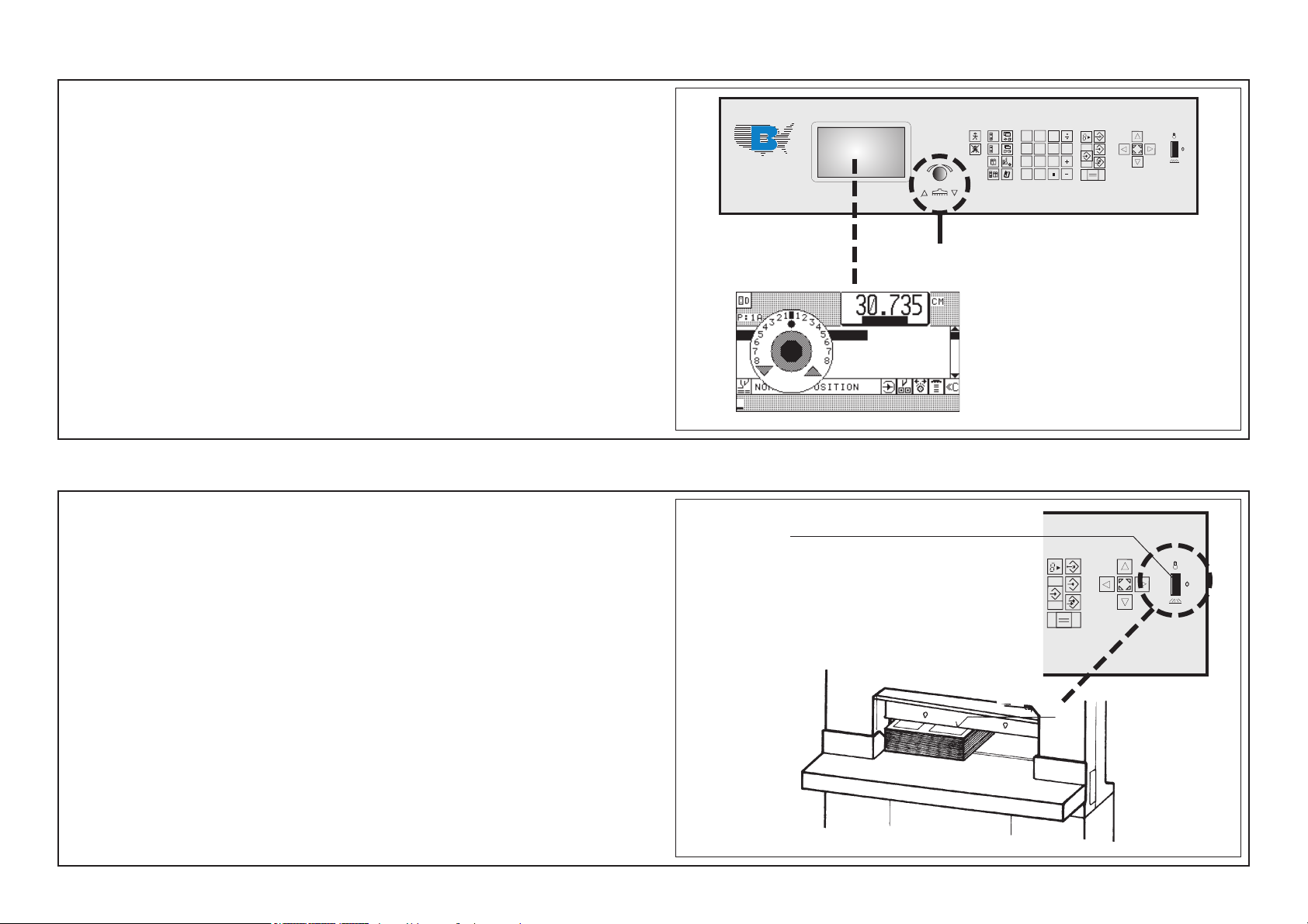
Setting of Measurements (Backgauge Movement) by Hand
1. Press electronical hand wheel and hold it in this position; turn hand wheel
to the left = forward movement of the backgauge
or to the right = reverse movement of the backgauge
The backgauge speed gets faster by turning the electronical hand wheel
to the left/right .
Cutting Line Indicator, Mechanical with Clamp
Lower clamp with pedal onto stock:
The front edge (a) of the clamp is identical to the cutting line and can be used as
cutting line indicator. Clamp can be stopped in any position.
Max pressure with fully activated pedal: 30 daN
i
3
8
Cutting Line Indicator, Optical
Actuate toggle switch (8) at main switch plate
Upper position: Table light ON
middle position: "0" - position
lower position: Optical cutting line indicator ON. A thin light line indicates the
cutting line; the table light is switched off at that moment.
K4 - 2
RAMMABLE
a
 Loading...