

Page 1
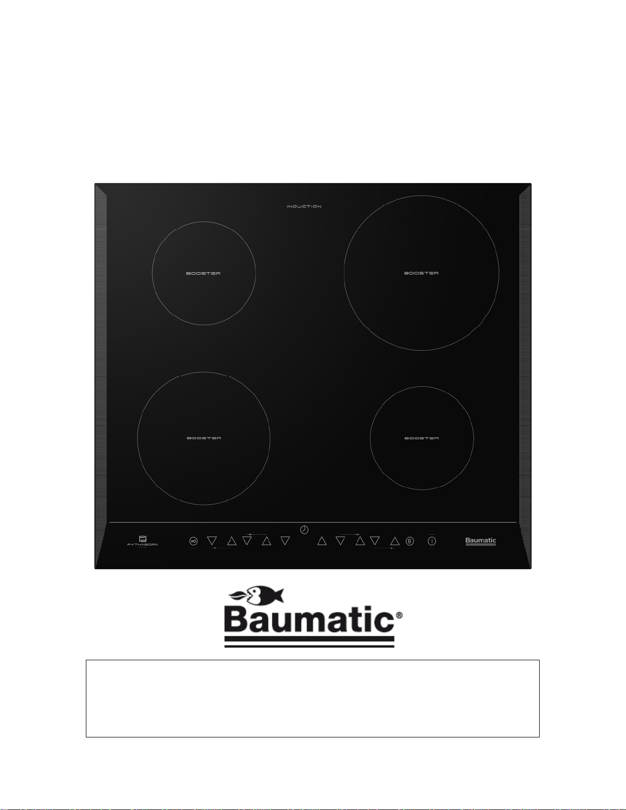
PI645 60cm Front
touch control
induction zone hob
1
Page 2
User Manual for your Baumatic
PI645
60 cm Front touch control
induction zone hob
NOTE: This User Instruction Manual contains important
information, including safety & installation points, which will
enable you to get the most out of your appliance. Please keep it
in a safe place so that it is easily available for future reference; for
you or any person not familiar with the operation of the appliance.
DD 23/02/09
2
Page 3

Contents
Environmental note 4
Important safety information 5 – 8
Specifications 9 - 11
Electrical details 10
Ceramic hob surface layout 10
Control panel layout 11
Using the ceramic hob 11 - 19
Before first use 11
Touch controls 12
Switching the hob on 12
Switching a zone on and setting a power level 12
Switching a zone off gradually 13
Switching a zone off instantly 13
Switching the hob off 13
Residual heat indicator 14
Pan sensor 14
Cookware that is suitable for an induction hob 15
Switching on the safety lock 15 - 16
Safety cut-out 16
Booster function 16 – 17
Switching off the booster function 17
The hob timer 17 – 18
Cooking zone temperature sensor 18
Hob guidelines 19
Cleaning and maintenance 20 - 21
Cleaning the ceramic hob top 20
After each use 20
Cleaning table 20
Using a ceramic hob scraper 21
Using a specialist ceramic hob cleaner 21
Installation 21 - 28
Positioning 22
Installing above a built under oven 23
Unpacking the appliance 23
Installing the appliance 24 – 25
Electrical connection 26
Connecting the mains supply cable 27 – 28
Replacing the mains supply cable 28
My appliance isn’t working correctly 29 – 31
Error codes 29
Contact details 32
3
Page 4
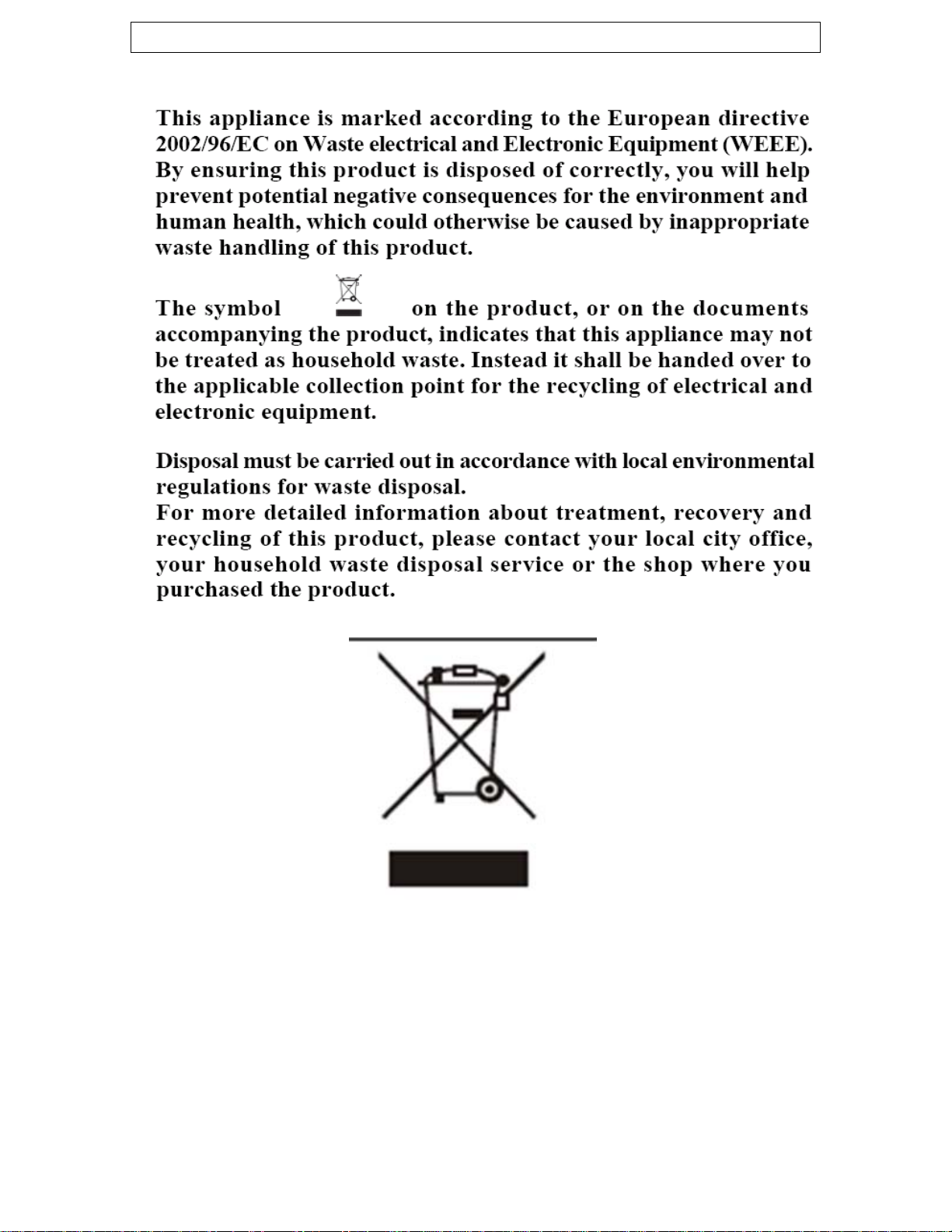
Environmental note
o The packaging materials that Baumatic uses are environmentally
friendly and can be recycled.
o Please discard
environment.
all packaging material with due regard for the
4
Page 5

Important safety information
Your safety is of the utmost importance to Baumatic.
Please make sure that you read this instruction booklet
before attempting to install or use the appliance. If yo
are unsure of any of the information contained in tu his
ooklet, please contact the Baumatic Advice Line.
b
General Information
This appliance is designed for domestic househo
the cooking and frying of domestic foodstuffs.
o IMPORTANT: The adjacent furniture and all materials used
the installation must be able to withstand a minimum
temperature of 85°C above the amb
room it is located in, whilst in use.
o Certain types of vinyl or laminate kitchen furniture are
particularly prone to heat damage or discolouratio
temperatures below the guidelines given above.
o Any damage caused by the appliance being installed in
contravention
the owner.
o Your new appliance is guaranteed against electrical or
mechanical defects, subject to certain exclusions that are noted
in Baumatic’s Conditions Of G
affect your statutory rights.
o The use of this appliance for any other purpose or in any other
environment without the express agreement o
will invalidate any warranty or liability claim.
o You shou
surface.
o No modifications to the appliance are permitted by Baumatic Ltd.
o You should not store or place flammable or highly flammable
liquids/materials on top of or near the appliance. Items made
from aluminium, plastic or plastic film should also be k
from the appliance, as they may fuse to the surface.
o Repairs may only be carried out by Baumatic
engineers or their authorised service agent.
of this temperature limit, will be the liability of
uarantee. The foregoing does not
ld not use this appliance to store items on or as a work
ient temperature of the
old use and for
n at
f Baumatic Ltd.
ept away
service
in
5
Page 6

hild Safety
C
o Baumatic strongly recommend that babies and young children
are prevented from being near to the appliance and not allowe
to touch the applianc
surfaces will be hot.
o If it is necessary for younger family members to be in the
kitchen, plea
at all times.
o Older children shou
when supervised.
eneral Safety
G
o The appliance should only
suitably qualified person.
o Care should be taken to ensure that the units and work su
that you bu
standards.
o If you notice any scratches, splits or cracks in the ceramic glass,
you should immediately switch off the appliance and disconnect
it from your main
shock occurring.
uring use
D
o Any film or stickers that are present on the h
is delivered should be removed before use.
o Care should be taken when utilising th
there is a risk of burns being caused.
o You should not allow the electrical connection cables to com
into contact
cookware.
o If fat and oil overheats, then it can ignite extremely quickly. For
this reason, when cookin
not be left unattended.
o Make
use.
sure that all of the cooking zones are switched off after
se ensure that they are kept under close supervision
ild the appliance into, meet with the relevant
with the hob surface when it is hot or any hot
e at any time. During and after use, all
ld only be allowed to utilise the appliance
be installed and connected by a
s supply. Otherwise there is the risk of electric
ob surface when it
e appliance, otherwise
g with fat and oil the appliance should
d
rfaces
e
6
Page 7
o IMPORTANT: This ceramic induction hob fully complies
with current legislation regarding electro-magnetic
interference and is designed not to interfere with other
electronic appliances providing these comply with the
same legislation.
o As the hob generates magnetic fields in its immediate
vicinity, pacemakers and active heart implants must be
designed to comply with relevant regulations. If in doubt,
you should consult the manufacturer of your device or
your doctor. In this respect, Baumatic can only guarantee
the conformity of our own product.
o If an object made of metal, (e.g. saucepan lid, knife, fork
or spoon) is placed on a cooking zone that is switched on,
it can get hot.
Cleaning
o Cleaning of the hob should be carried out on a regular basis.
o IMPORTANT: Before attempting to clean the appliance, it
should be disconnected from the mains and allowed to cool.
o Great care should be taken whilst using this appliance and when
following the cleaning procedure.
o You should not use a steam jet or any other high pressure
cleaning equipment to clean the appliance.
Installation
This appliance must be correctly installed by a
suitably qualified person, strictly in accordance
with the manufacturer’s instructions. Please see
the specific section of this booklet that refers to
installation.
Baumatic Ltd. declines any responsibility for injury or damage,
to person or property, as a result of improper use or incorrect
installation of this appliance.
7
Page 8

Declaration of conformity
This appliance complies with the following European Directives:
-73/23/EEC dated 19/02/1973 Low Voltage Directive.
-89/336/EEC dated 03/05/1989 EMC Directive inclusive of
Amending Directive 92/31/EEC.
-93/68/EEC dated 22/07/1993 CE Marking Directive.
-89/109/EEC dated 25/01/1992 Materials that can touch food.
o The manufacturer declares that the hob is built using certified
materials and requires the appliance to be installed in
accordance with the standards currently in force. This appliance
must be used by a trained person for domestic purposes only.
To avoid damaging your appliance
o The ceramic glass can be damaged by objects falling onto it.
o The ceramic glass edge can be damaged by knocks from
cookware.
o Cast iron and cast aluminium cookware with damaged bases
may scratch the ceramic surface if they are dragged across it.
o Pans should be lifted on and off the hob surface and not
dragged.
o Cooking zones should not be switched on without cookware
placed on it. Also the cookware should not be empty.
o Food or liquid that has high sugar content may damage the hob
top, if it comes into contact with the ceramic hob surface. Any
spillages should be wiped up immediately, however this may not
prevent the hob surface from becoming damaged.
8
Page 9
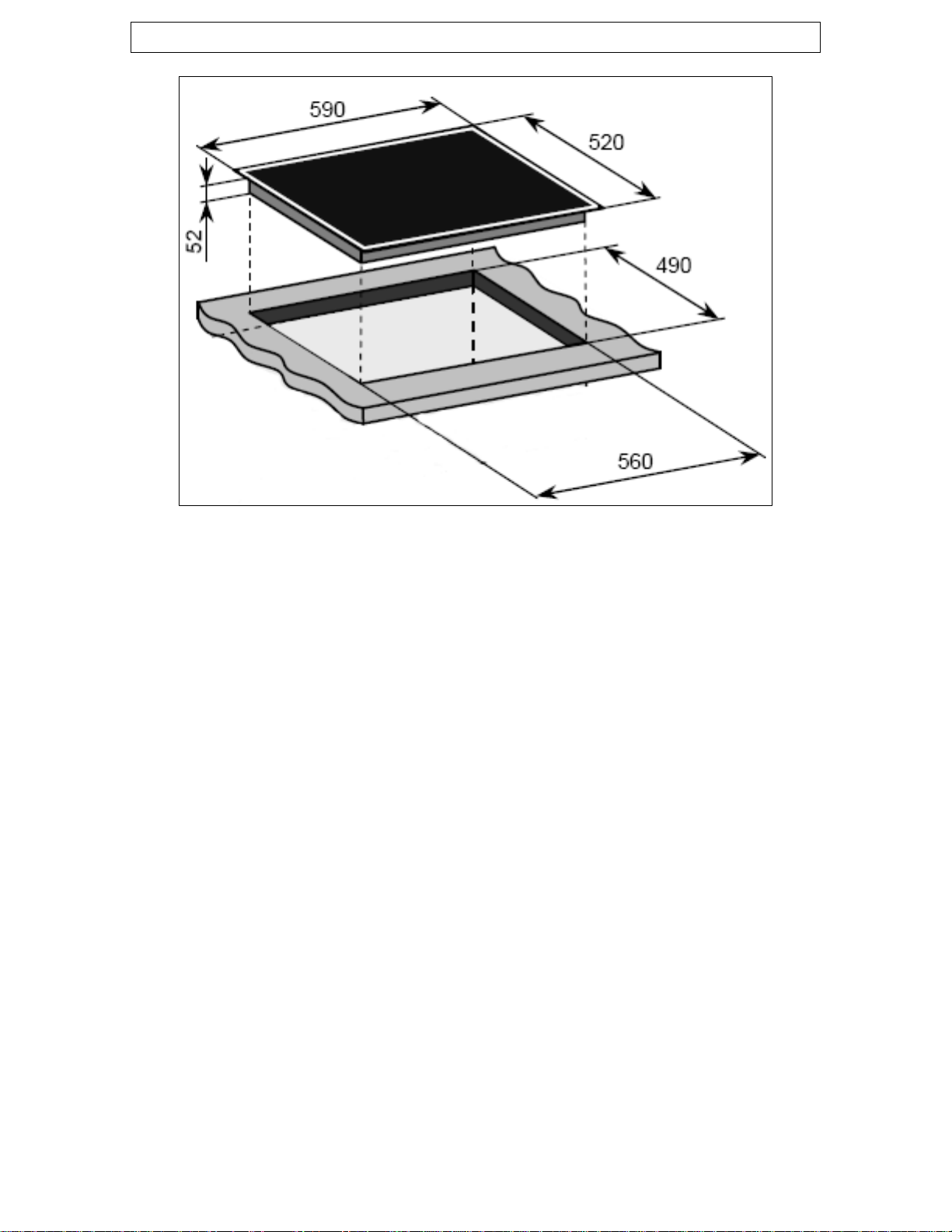
Specifications
Product dimensions: Aperture dimensions:
Height: 520 mm Height: 490 mm
Width: 590 mm Width: 560 mm
Depth: 52 mm
Product specifications:
o 1 x 2.00 kW induction zone with booster (2.6 kW)- diametre 210
mm
o 2 x 1.40 kW induction zones with booster (2.0 kW)- diametre
180 mm
o 1 x 2.00 kW induction zone with booster (2.6 kW)- diametre 180
mm
o Front touch control operation
o Timer
o 4 individual residual heat indicators
o Safety lock
o Frameless with bevelled edges effect
o Suitable for installation above built-under ovens. IMPORTANT:
Providing that the specific installation instructions in this
manual are followed.
Standard accessories
o Ceramic hob scraper
9
Page 10
Electrical details
Rated Voltage: 230 Vac 50 Hz
Supply Connection: 32 A (double pole switched fused
outlet with 3mm contact gap)
Max Rated Inputs: 7.00 kW
Mains Supply Lead: 3 core x 6 mm² (not supplied)
For future reference please record the following information which can
be found on the rating plate and the date of purchase which can be
found on your sales invoice. The rating plate of your hob is located on
the underneath of the appliance. Therefore it is a good idea to record
this information before you install your appliance.
Model Number ……………………………….
Serial Number ……………………………….
Date of Purchase ……………………………….
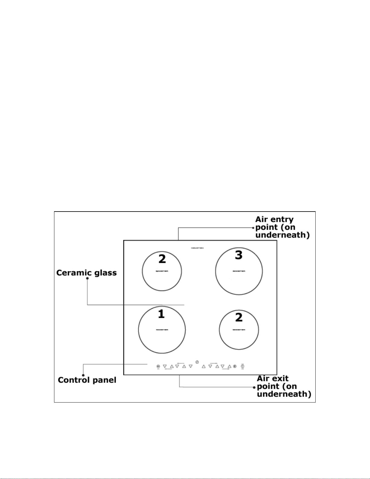
Ceramic hob surface layout
1) 2.00 kW induction zone (210 mm)
2) 1.40 kW induction zone (180 mm)
3) 2.00 kW induction zone (180 mm)
10
Page 11
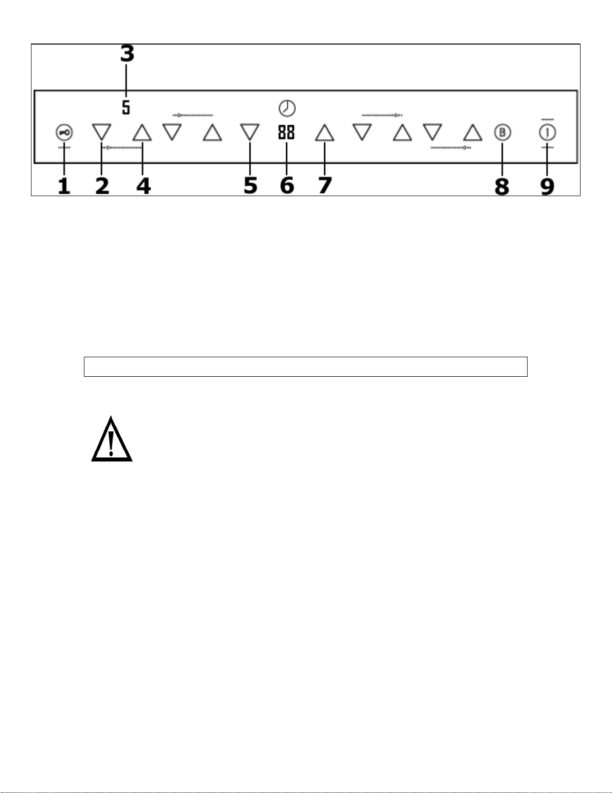
Control panel layout
1) Safety lock button
2) Minus button (x 4)
3) Cooking zone indicator (x 4)
4) Plus button (x 4)
5) Timer minus button
6) Timer display
7) Timer plus button
8) Booster button
9) ON/OFF button
Using the ceramic hob
Before first use
IMPORTANT: You should clean the ceramic hob surface (see
“Cleaning and maintenance” section).
o You should switch on one cooking zone at a time, for 5 minutes
at the maximum setting. This will help to eliminate any new
smell that exists and evaporate any humidity that has formed
during transit.
o Do not burn off more than one zone at once.
o You must place a saucepan filled half full with cold water on
each zone as you burn it off. Otherwise the induction zone will
not operate.
11
Page 12

Touch controls
o All operations are performed by means of the touch controls that
can be found on the control panel.
o Each touch control has a visual display that corresponds to it.
o Every time you press a touch control, an acoustic signal will
sound.
Switching the hob on
o Press the ON/OFF button (9)
o The cooking zone indicators (3) will all read “0”.
Switching a zone on and setting a power level
IMPORTANT: A zone must be selected within two minutes of
switching the hob on.
o Press the plus button (4) for the zone that you
want to use.
o A number “5” will appear on the relevant
cooking zone indicator (3). Indicating that a
power level of 5 is currently selected.
o Adjust the zone between power levels 1 and 9,
using the plus (4) and minus (2) buttons. By
holding down either of these buttons, the value
on the cooking zone indicator (3) will adjust up
or down every 0.3 seconds.
o If when holding down the plus (4) or minus (2) buttons the
power level reaches zero. You will need to press either the plus
(4) or minus (2) button again, to continue adjusting the power
level.
12
Page 13

Switching a zone off gradually
o Press the minus button (2) of the zone that
you wish to switch off, until the number in the
cooking zone indicator (3) reaches “0”. After 3
seconds, the zone will switch off automatically.
o An “H” will show in the cooking zone indicator
(3) until the temperature of the zone falls
below 60°C (see the section on the “residual
heat indicator” for further information).
Switching a zone off instantly
o Simultaneously press the minus button (2)
and the plus button (4) of the zone that you
wish to switch off.
o The zone will switch off immediately.
o An “H” will show in the cooking zone indicator
(3), alternating with “0”. (See the section on
the “residual heat indicator” for further
information).
Switching the hob off
Once you have switched off all of the cooking zones, you should switch
the hob off.
o Press the ON/OFF button (9).
o It is possible to switch off the hob off at any time by
pressing the ON/OFF button (9).
13
Page 14

Residual heat indicator
o After a zone is switched off, the corresponding
cooking zone indicator (3) will show the letter “H”.
This means that the temperature of the zone is
over 60°C and is therefore still high enough to
cause injury.
o If the zone falls below 60°C and there are still other zones
switched on, a “0” will appear on the cooking zone indicator (3).
o IMPORTANT: The residual heat indicator will disappear if your
mains supply is cut.
Pan sensor
Each zone has a sensor on it, so it can detect the presence of a pan.
o The sensor is fine-tuned to detect a pan being placed on it. The
pan should be one size smaller than the nominal diameter of the
zone.
o If a “U” shaped symbol appears on a cooking zone indicator (3),
after you have placed a pan on that cooking zone and attempted
to set a power level; this means that the pan is either the
incorrect size or shape. Or it could be made from a material that
is inappropriate for use on an induction zone hob.
o The pan should have a flat bottom and be larger than 120 mm in
diametre.
o If a cooking zone is selected but no pan is detected, the pan
sensor system will check for the presence of a pan
approximately every 2 seconds.
o You should check that your pans are suitable for use on an
induction zone hob (see the pan manufacturer’s trademark or
instructions).
o If a saucepan smaller than 80 mm in diameter or a small object
(such as cutlery) is placed accidentally on a cooking zone. An
audible alarm will sound for approximately 1 minute.
o If the saucepan or small object is not removed from the cooking
zone, then the hob will enter stand-by mode.
14
Page 15

Cookware that is suitable for an induction hob
The table below shows cookware that is normally suitable for use on
an induction zone hob:-
Cookware Suitable
Steel, enamelled steel Yes
Cast iron Yes
Stainless steel Yes (if stated by the pan
manufacturer)
Aluminium, copper, brass No
Glass, ceramic, porcelain No
o The bottom of the pans should be as flat and thick as possible.
o Certain types of cookware may result in a noise being made
when being used on an induction zone hob. This does not mean
that there is an appliance fault.
o IMPORTANT: You should make sure that all pans are placed in
the centre of the induction zone that you are using.
Switching on the safety lock
It is possible to lock the hob top, so that none of the cooking zones
can be switched on.
o Switch on the hob using the ON/OFF button (9).
o The whole hob top can be locked by pressing the
safety lock button for a few seconds (1) whilst the
appliance is switched on.
o The timer display (6) will show a key symbol (
to confirm that the safety lock feature has been
switched on.
o When the safety lock feature is activated, it will disable any of
the other buttons on the control panel, except the ON/OFF
button (9).
o To disable the safety lock feature, you should press the safety
lock button (1) again for a few seconds, until the key symbol on
the timer display (6) has gone off.
o You will then be able to adjust the power of any zone on the hob
top.
15
)
Page 16

o IMPORTANT: If the appliance is switched off whilst the safety
lock feature is activated, then it will still be activated the next
time that you switch the appliance on. Therefore before you can
switch on a zone and set it to a power level, you will need to
deactivate the safety lock by pressing the safety lock button (1).
Safety cut-out
o If one or more of the cooking zones are accidentally left on, a
safety cut out will activate after a certain period of time. The
length of time depends on the power level that a zone or zones
have been switched on for.
LEVEL TIME LIMIT
1 – 3 8 hours
4 - 6 4 hours
7 – 9 2 hours
o If the safety cut out has activated, the symbol “H” will appear in
the cooking zone indicator (3) of the cooking zone that has been
left on. To reset the appliance, you should press the ON/OFF
button (9).
o If the plus (4) or minus (2) buttons are pressed, then the
length of time before the safety cut-out will activate is reset.
Booster function
The hob has a booster function which will increase the power output of
a zone for a five minute period.
o Switch on the hob, select and set the power level of a
cooking zone as normal.
o Press the booster button (8) and the power output of
the relevant zone will increase to the levels shown
below:-
Front left zone - 2.60 kW
Back left zone - 2.00 kW
Front right zone - 2.00 kW
Back left zone - 2.60 kW
16
Page 17

o The booster time is limited to 5 minutes and will switch off
automatically after this time. The zone will then return to its
original power level.
o If the saucepa
switched on, then the boosting function will remain active and
the boosting time will continue until the 5 minute booster pe
has elapsed.
o The hob has two generators which create the power for the
zones; there is one generator for each side of the hob.
o If the booster function is switched on, when the zone on the
same side of the hob is already active. The generator will diver
power from the other zone and reduc
o You will see the reduced power le
relevant cooking zone indicator (3).
Switching off the booster fun
o Press the plus button (4) of the zone that you wish to switch th
booster function off
o Either press the booster button (8) or the minus button (2) of
the relevant zone.
The booster function will switch off. IMPORTANT: The zone will
o
not switch o
as normal.
The hob timer
n is removed from the zone when the booster is
e it to power level 2.
vel of the zone shown in the
ction
for.
ff entirely; you will still need to switch off the zone
o Switch on the hob using the ON/OFF button
(9).
o Press the plus button (4) for the zone tha
you want to use.
o A number “5” will appear on the relevant
cooking zone indicator (3).
o Adjust the zone between power levels 1 and
9
, using the plus (4) and minus (2) buttons.
By holding down either of these buttons, the
value on the cooking zone indicator (3) will
adjust up or down every 0.3 seconds.
riod
t
e
t
17
Page 18

o Immediately use the timer
and timer plus (7) buttons, to set the
countdown time that you requir
o The countdown time will appear on
the timer display (6).
o When the countdown time that you require appears on the timer
display (6), stop pressing the timer minus (5) and timer plus
(7) buttons.
o The number on the timer display (6) will flash for five second
After it has stopped flashing, the countdown time is set.
The countdown will start immediately. An acoustic signal will
o
sound at the end of the countdown time that you have set. The
zone that has been linked to timer will switch off.
o IMPORTANT: If you have any o
they will not switch off at the end of the countdown time.
Cooking zone temperature se
A temperature sensor is situated in the middle of each cooking zone
and is in contact with the glass.
o In the event of a cooking zone overheating, this will be note
the temperature sensor.
If the cooking zone temperature sensor records too high a
o
temperature, then the electronic circuit will shut down the
appliance.
o A cooking zone overheating could be caused by an empty
saucepan being placed on an active zone.
o If the bottom of the pan is not fully in contact with the middle of
a cooking zone, then the cooking zone temperature con
not function correctly.
o IMPORTANT: If the cooking zone temperature sensor
consistently shuts
hob has not
ventilation is not large enough. Steps should be taken to rectify
this immediately.
been installed properly or the opening for air
down the appliance. This indicates that the
nsor
ther cooking zones switched on,
minus (5)
e.
d by
trol may
s.
18
Page 19

Hob guidelines
o The fi
burning smell. This smell will disappear completely with repeated
use.
o The hob surface is fitted with cooking areas of different diametre
and power.
o The positions where the heat will radiate from are clearly marked
on the hob top. The saucepans must be positioned exactly on
these zones for efficient heating to occur. Pans should have the
same diametre as the cooking zone that they are being used on
o You should not use saucepans with rough bottoms, as this can
scratch the ceramic surface.
o Before use, make sure that the bottoms of the saucepans are
clean and dry.
o When cold, the bottom of the pans should b
they expand when hot and lie flat on the surface of the hob. This
will allow the heat to transfer more easily.
o The best thickn
enamelled steel and 4 – 6 mm for stainless steel with sandwich
type bottoms.
If these rules are not followed, then there will be a great waste
o
of energy.
o Preferably cover pans with a lid to permit cooking at a lower
heat.
Always cook vegetables and potatoes, etc. in as little water as
o
possible to reduce cooking times.
o Food or liquid that has high sugar content may damage the hob
top if it comes into contact with the ceramic hob su
spillages should be wiped up immediately, however this may not
prevent the hob surface from becoming damaged.
o IMPORTANT: The hob surface is tough; however
unbreakable and can be damaged. Especially if pointed or hard
objects are allowed to fall on it with some force.
o DO NOT USE THE HOB IF THE SURFACE
OR CRACKED. YOU SHOULD
SERVICE DEPARTMENT IMMEDIATELY.
rst few times the hob top is used, it may give off an acrid,
e slightly concave, as
ess for the bottom of the pans is 2 – 3 mm of
rface. Any
it is not
BECOMES BROKEN
CONTACT THE BAUMATIC
.
19
Page 20

Cleaning and maintenance
Cleaning operations must only be carried out
when the hob is cool.
The appliance should be disconnected from your
mains supply befo
process.
n
Clea
After each use
Cleaning table
Type of deposit Remove
Sugar or
food/liquid
containing sugar
Tin foil or plastic Yes No Ceramic hob
Fat splashes No Yes Ceramic hob
Metallic
discolourations
Water splashes or
ing the ceramic hob top
ny residues that are left on the hob top surface from cleaning
A
agents will damage it. You should remove any residues with
warm water mixed with a little washing up liquid.
Abrasive c
you should clean it using warm water mixed with a little wa
up liquid.
Although it is easier to clean some deposits whilst the hob
surface is s
cleaning the hob surface when it is still warm.
o Wipe the appliance over with a damp cloth.
o liance by rubbing the surface with a clean cloth.
Dry the app
ater rings
leaners or sharp objects will damage the hob surface;
till warm. You should take care not to burn yourself if
immediately?
Yes No Ceramic hob
No Yes Ceramic hob
No wYes Ceramic hob
re commencing any cleaning
Remove
when the
has
down?
20
lianapp
ce
cooled
What should I
use to remove
the deposit?
scraper
scraper
cleaner
cleaner
cleaner
shing
Page 21

Using a ceramic hob scraper
Your applia
uidelines should also be followed when using the ceramic hob
g
craper:-
s
o The scraper should be placed on the ceramic surface at an angle
o Residues should be removed by sliding the blade carefully over
the ceramic surface.
o The ceramic surface
been placed in warm water mixed with a small amount of
washing up liquid.
o Dry the appliance by rubbing the surfa
Using a specialist ceramic hob cleaner
It is possible to purchase a specialist ceramic hob cleaner/conditione
You should follow the in
pecialist ceramic hob cleaner. You should ensure that it is suitable for
s
use on your appl
nce will be provided with a hob scraper. The following
should be wiped with a damp cloth that has
ce with a clean cloth.
structions given by the manufacturer of the
iance.
.
r.
Installati n
o UK Regulations and Safety Standards or their Europe
Norm Replace
o Building Regulations (issued by the Department of the
Environment).
o Building Standards (issue
Department).
o IEE Wiring Regulations.
o Electricity At Work Regulations.
o
The installation must be carried out by a suitably
ualified person, in accordance with the current
q
version of the following.
ments.
d by the Scottish Development
21
an
Page 22

i
Position
This appliance is classified as Class 3 and therefore is to be built into a
kitchen unit (dependi
5 mm and 40 mm thick. The following minimum clearance distances
2
must be observed:-
o 700 mm between the hob surface and the underside of any
o 50 mm clearance around the sides and front of the appliance.
o 55 mm clearance between the back of the hob surface and the
o If the hob is positioned so that the right or left hand side of the
o IMPORTANT: Underneath the appliance there must be a
You must make sure that there is a 5mm gap below the
o
ng
The adjacent furniture must be able to withstan
minimum tempe
temperature of the room it is located in, during
periods of use.
ng on size) or 600 mm worktop that is between
horizontal surface above it.
wall behind it.
appliance will be near to the edge of
be a gap of at least 150 mm between the side of the hob and the
vertical surface of the kitchen unit.
partition made of insulating m
a gap of at least 50 mm between the underneath of the
appliance and this partition.
underneath of the worktop at the front edge of the hob.
rature rise of 85°C above the ambient
a kitchen unit. There must
aterial (e.g. wood). There must be
d a
22
Page 23

Installing above a built under oven
MPORTANT: If you are building this hob above an oven, the
I
oven MUST have a cooling fan.
There must be a gap of at least 50 mm between the underneath
o
of the appliance and the top of the oven.
o You must make sure that there is a 5mm gap below the
underneath of the work
Unpacking the appliance
hen unpacking the appliance please check that the following items
W
are contained wit
1 Baumatic hob
1 Ceramic hob scraper
1 Installation and
1 Baumatic guar
4 Fixing bracket
Fixing screws
4
Sealing strip
1
hin the packaging:
instruction manual
antee card
s
top at the front edge of the hob.
23
Page 24

Installing the appliance
Cut a hole in the worktop that corresponds with the drawing
o
shown above.
o Apply the sealing strip provided around the edge of the
appliance.
o The protective covering must be removed from both sides.
o Do not leave a gap in the sealing agent or overlap the thickness.
o IMPORTANT: Do not use a silicon sealant to seal the ap
against th
from the aperture in future, particularly if it needs to be
serviced.
e aperture. This will make it difficult to remove the hob
24
pliance
Page 25

o Carefully tu
aperture ho
o There are holes on the base or th
fix the four brackets to. There ar
brackets.
rn the hob back over and then gently lower it into
le that you have cut out.
o IMPORTANT
holes around the outside of the hob.
YOU MUST ensure that these holes a
not blocked by the work to
put the hob into position (see drawing
opposite).
o Carefully turn the hob upside down and
place it on a cushioned mat.
the
: There are ventilation
re
p, when you
e sides of the hob that you can
e three holes in each one of the
o You should place the
bracket on the underneath
of the hob, in a position
that is appropriate
aperture th
out. Using the screws
provided, fix the bracket
to the hob. These screws
MUST be securely
tightened.
at you have cut
for the
25
Page 26

Electrical c
efore connecting the appliance, make sure that the supply voltage
B
marked on the rating plate corresponds with your mains supply
voltage.
WARNING: THIS APPLIANCE MUST BE EARTHED.
This appliance must be wired into a 32 A double pole switched
o
fused spur outlet, having 3 mm contact separation and placed in
an easily accessible position adjac
not be located above the appliance and no more than 1.25m
away from it.
o The spur outlet must still be accessible even when your oven is
located in its operating position.
o Cable type: H05 RRF 3 core x 6 mm²
We recommend that the appliance is connected by a qualified
o
electrician, who is a m .I.C. and who will
comply with the I.E The wires in the
mains lead should ith the following
UK code:
onnection
This appliance must be installed by a qualified
person in accordance with the latest edition of t
I.E.E. Regulations and in compliance with Baumatic’s
instructions.
ent to the appliance. It should
ember of the N.I.C.E
.E. and local regulations.
be coloured in accordance w
Brown/Red = Live
Black/Blue = Neutral
Green/Yellow = Ground
he
26
Page 27

Connecting the mains supply cable
o
The mains terminal block is located on the underside of the hob
and the terminals are accessible by removing the terminal block
cover by removing the cover screw.
o The mains terminal block is located on the un
and the terminals are accessible by removing the terminal block
cover. You should remove the cover screw to access this.
o The cable connections must be in accordance with the diagram
located on the bottom of the hob and below.
derside of the hob
o 1 and 2 are the live connection, 3 and 4 are the neutral
connection and the remaining one is the earth connection.
27
Page 28

o The brass links must be positioned as marked in the diagram
the previous page and once established ALL terminal screws
must be tightened down firmly.
o If when the hob is first switched on, only two
work, you should recheck that the terminal screws are all
fully tightened between the links. This should be done
before contacting the Baumatic Service Department.
o T: The appliance must NOT be connected to the
IMPORTAN
ains supply by means of a 13A plug and socket.
m
o The cable can be looped if necessary, but make sure that is not
kinked or trapped when the hob is in position. Care must be
taken to avoid the ca
appliance.
Replacing the mains
If the mains supply cable is damaged, then it must be repl
opriate replacement.
ppra
mains supply cable should be replaced in accordance with the
hT e
following instructions:
o Switch the appliance off at the control switch.
o Open the terminal block on the underside of the hob.
o th
Unscrew e terminal screws fixing the cable.
o eplace the cable with one of the same length and in accordance
R
with the specification given on page 26.
o e terminal
The “green-yellow” earth wire must be connected to th
arked
m . It must be about 10 mm longer than the live and
eutral wires.
n
o he “black/blue” neutral wire must be connected to the terminal
T
arked with the letter (N) - the brown/red live wire must be
m
onnected to the terminal marked with the letter (L).
c
ble being in contact with hot parts of the
supply cable
of the zones
aced by an
on
28
Page 29

My appliance isn’t working correctly
Error codes
Error code ble causes Possi Solution
F0/F1/F2 Fan failure Contact the Baumatic
Service Department
F3 – F8 re sensor Temperatu
failure
E1/E2 Abnormal supply
voltage
E3/E4 High zone
temperature
E5/E6 High hob temperature Allow the hob to cool
* IMPORTANT: If these error codes appear frequently, then check
that the installation of the hob has been completed correctly. In
particular, pay attention to the ventilation requirements specified in
this manual.
Contact the Baumatic
Service Department
Check that the power
supply the hob is
connected to is
appropriate. (See th
diagram on page 27e ).
Allow the hob to coo
and then restart it. *l
o The cooking zones are not functioning or will not switch
on.
* It has been more than two minutes since the appliance was
switched on. You should switch the appliance on again, using the
ON/OFF button.
* You have not placed an appropriate pan on the zone that you are
trying to get to heat.
* The safety lock has been switched on (see the “Switching on the
safety lock” section for information on how to turn off the safety
lock).
* Several touch control buttons have been pressed at once. You
should only touch one touch control b
utton at a time.
* The safety cut out has been triggered. Press the ON/OFF button
(9) to reset the appliance.
* Check that the mains electrical supply to the appliance is correct
and working. Check the mains fuse.
and then restart it. *
29
Page 30

o The residual heat indicator has not come on after I have
switched a cooking zone off.
* The cooking zone has only been turned on for a short period of
time; therefore it did not go above 60°C.
IMPORTANT: If the cooking zone does appear to be hotter than
*
60°C and the residual heat indicator has not come on, you
should call the Baumatic Service Department.
A humming sound is heard when a cooking zone is
o
selected.
This is normal; the sound will disappear when the zone heats up*
o The cooking zones have become discoloured
* This maybe caused by burnt on remnants of food. This wi
affect the working of the applia
sure that the cleaning instructions are being followed regularly.
nce. However you should make
o Only two of the zones on my hob are working
* You should recheck that the terminal screws are all fully
tightened between the links.
.
ll not
30
Page 31

IMPORTANT: If your appliance appears not to
operating correctly, then you should disconnect it
from your mains supply and then contact
Baumatic Customer Care on telephone number
(0118) 933 6911.
DO NOT ATTEMPT TO REPAIR THE APPLIANCE
YOURSELF.
Please note that if an engineer is asked to attend whilst the product is
under guarantee and finds that the problem is not the result of an
appliance
harge.
c
The appliance must be accessible for the engineer to perform
any necessary repair. If your appliance is installed in such a
way that an engineer is concerned that damage will be caused
the appliance or your kitchen, then he will not complete a
to
repair.
his includes situations where appliances have been tiled in,
T
ealed in with sealant, have wooden obstructions placed in
s
ront of the appliance, like plinths. Or any installation other
f
han the one specified by Baumatic Ltd. has been completed.
t
lease refer to the conditions of guarantee that appear on the
P
arranty card that you receive with the appliance.
w
fault, then you may be liable for the cost of the call out
31
be
Page 32

United Kingdom
Baumatic Ltd.,
Baumatic Buildings,
6 Bennet Road,
Reading, Berkshire
RG2 0QX
United Kingdom
Sales Telephone
(0118) 933 6900
Sales Fax
(0118) 931 0035
Customer Care Telephone
(0118) 933 6911
Customer Care Fax
(0118) 986 9124
Spares Telephone
(01235) 437244
Advice Line Telephon
(0118) 933 693
3
e
-mail:
E
ales@baumatic.co.uk
s
ustomercare@baumatic.co.uk
c
pares@baumatic.co.uk
s
chnical@baumatic.co.uk
te
ebsite:
W
ww.baumatic.co.uk
w
epublic of Ireland
R
1- 6266 798
0
Czech Republic
aumatic CR SPOL. S.R.O.
B
46215, Libr
The Czech Repub
ec
lic
+4204 8357 7200
ww.baumatic.cz
w
ermany
G
Baumatic GMBH
nderstrasse 9
Ja
Mannh
eim, 68199
Germany
+4962 112 9190
ww.baumatic.de
w
taly
I
Baumatic Italia S.
ia Caltana 129
V
Campodar
sego (Padova), 35011
R.L.
Italy
+3904 9920 2297
ww.baumatic.it
w
olland
H
Baumatic Benelux
rind Zuigerstraat 22
G
B.V.
ALMERE, 1333 MS
The Netherlands
+3136 549 1555
www.baumatic.nl
32
Page 33

33
Page 34

34
Page 35

35
Page 36

36
 Loading...