

Page 1
B602.1BL/W
B604.1SS/B609.1SS
60 cm Gas fan-assisted
oven
1
Page 2
User Manual for your Baumatic
B602.1BL/W
B604.1SS
B609.1SS
60 cm Gas fan-assisted oven
NOTE: This User Instruction Manual contains important
information, including safety & installation points, which will
enable you to get the most out of your appliance. Please keep it
in a safe place so that it is easily available for future reference; for
you or any person not familiar with the operation of the appliance.
DD 23/03/09
2
Page 3

Contents
Environmental note 4
Important safety information 5 – 8
Specifications 9
Product specifications 9
Standard accessories 10
Optional extras 10
Electrical details 10
Control panel 11
Before first use 12
Setting the time of day (B609.1SS only) 12
Switching the gas oven on 13
Switching the gas grill on 14
Operation of the fan 15
Cooking guidelines 15
Warnings 16
Setting a countdown time (B609.1SS only) 17
Using the minute minder (B602.1 & B604.1 only) 18
The oven light 18
Cleaning and maintenance 19
Replacing the oven bulb 20
Removing the oven door for cleaning 21
Removing the inner door glass for cleaning 22
Installation 22
Electrical connection 22-23
Positioning 23
Installing the oven into the kitchen cabinet 24
Positioning the appliance 24
Ventilation requirements 25-26
Gas connection 27
Gas Safety (Installation and Use) Regulations 28
Gas connection 29
Gas adjustment (Conversion to LPG and gas adjustment) 30-32
My appliance isn’t working correctly 32-33
Baumatic Ltd. conditions of guarantee 34
Contact details 35
3
Page 4
Environmental note
o The packaging materials that Baumatic uses are environmentally
friendly and can be recycled.
o Please discard
environment.
all packaging material with due regard for the
4
Page 5

IMPORTANT SAFETY INFORMATION
Your safety is of the utmost importance to Baumatic.
Please make sure that you read this instruction booklet
before attempting to install or use the appliance. If yo
are unsure of any of the information contained i
booklet, pleas
Departm
eneral Information
G
ent.
e contact the Baumatic Technical
o This appliance is designed for domestic household use an
be built into a standard kitchen cabinet or housing unit.
o IMPORTANT: The adjacent furniture or housing and all
materials used in the installation must be able to withstand a
minimum temperature of 85°C above the
of the room it is located in, whilst in use.
o Certain types of vinyl or laminate kitchen furniture are
particularly prone to heat damage or discolouratio
temperatures below the guidelines given above.
o Any damage caused by the appliance being installed in
contravention of this temperature limit, or by placing adjacent
cabinet materials closer t
liability of the owner.
o For use in leisure accommodation vehicles, please refer to
the appropriate info
for this appliance.
o IMPORTANT: Baumatic Ltd. DO NOT recommend t
appliance is installed on any type of marine vessel.
o The use of this appliance for any other purpose or in any other
environment without the express agreement o
will invalidate any warranty or liability claim.
o Your new appliance is guaranteed against electrical or
mechanical defects, subject to certain exclusions that are noted
in Baumatic’s Conditions Of G
affect your statutory rights.
rmation given in the installation instructions
han 4mm to the appliance, will be the
uarantee. The foregoing does not
ambient temperature
n at
hat this
f Baumatic Ltd.
o Repairs may only be carried out by Baumatic
Engineers or their authorised service agent.
Service
u
n this
d can
5
Page 6

arning and safety instructions
W
o This appliance complies with all current European safety
legislation. Baumatic do wish to emphasise that this compl
does not remove the fact that the appliance surfaces will
become hot during use and retain heat after operation.
hild Safety
C
iance
o Baumatic strongly recommend that babies and young children
are prevented from being near to the appliance and not allowe
to touch the appliance at a
surfaces will become hot.
o If it is necessary for younger family members to be in the
kitchen, plea
at all times.
eneral Safety
G
Make sure that you understand the controls before using the
appliance.
Check that all of the controls on the appliance are turned off
after use.
when opening the oven door, this will allow
Always stand back
eat to disperse.
h
Take care when removing items from the oven, as the contents
may be hot.
Always keep the oven doors closed when the oven is not in use.
Always follow the basic principles of food handling and hygiene,
this will prevent the possibility of bacterial growth.
Always keep ventilation slots clear of obstructions.
Keep fingers away from the hinge areas when closing the door,
otherwise you may trap them.
Oven gloves should be used when placing food in the oven ca
and when removing it. Care should be taken to avo
contact with any of the elements in the appliance.
se ensure that they are kept under close supervision
ny time. During and after use, all
id direct
o DO NO
USE.
T LEAVE THE APPLIANCE UNATTENDED WHILST IN
d
vity
6
Page 7

o Do not place heavy objects on the oven door or lean on the
oven door when it is open, as this can cause damage to the oven
door hinges. Nobody should be allowed to sit or stand on any
part of the oven.
o Do not heat up unopened food containers, as pressure can build
up which may cause the container to burst.
o Do not place flammable or plastic items in the oven.
o Do not leave heated oil or fat unattended, as this is a fire risk.
o Do not allow fat or oil to build up in the oven trays, grill pan or
oven base.
o Do not place pans or baking trays directly on the base of the
oven cavity, or line it with aluminium foil.
o Do not grill food containing fat without using the grill trivet. The
grill trivet should never be covered with aluminium foil.
o Do not place hot enamel parts in water, leave them to cool first.
o Do not allow vinegar, coffee, milk, saltwater, lemon, tomato
juice or any liquid with high sugar content to remain in contact
with the enamel parts of the appliance. Spillages should be
wiped up immediately.
o Do not allow electrical fittings or cables to come into contact
with areas on the appliance that get hot.
o Do not use the appliance to heat the room it is located in or to
dry clothing. No clothing should be placed over or near to the
oven door.
o Do not install the appliance next to curtains or soft furnishings.
o Do not attempt to lift or move cooking appliances by using the
oven door or handle, as this may cause damage to the appliance
or result in injury to the person lifting the appliance.
o Do not store chemicals, food stuffs, pressurised containers in or
on the oven or in cabinets immediately above or next to the
oven.
7
Page 8

Cleaning
o Cleaning of the oven should be carried out on a regular basis.
o Great care should be taken whilst using this appliance and when
following the cleaning procedure.
o IMPORTANT: The appliance must be disconnected from the
mains before following the cleaning procedure.
Installation
This appliance must be correctly installed by a
suitably qualified person, strictly in accordance
with the manufacturer’s instructions. Please see
the specific section of this booklet that refers to
installation.
o Baumatic Ltd. declines any responsibility for injury or
damage, to person or property, as a result of improper
use or installation of this appliance.
o Heat, steam and moisture will be created during use of the
appliance, take care to avoid injury and ensure that the room is
adequately ventilated. If the appliance is going to be used for
prolonged periods of time, then additional ventilation may be
required.
o Please consult with your qualified installer if you are in any doubt
about the amount of ventilation that you will require.
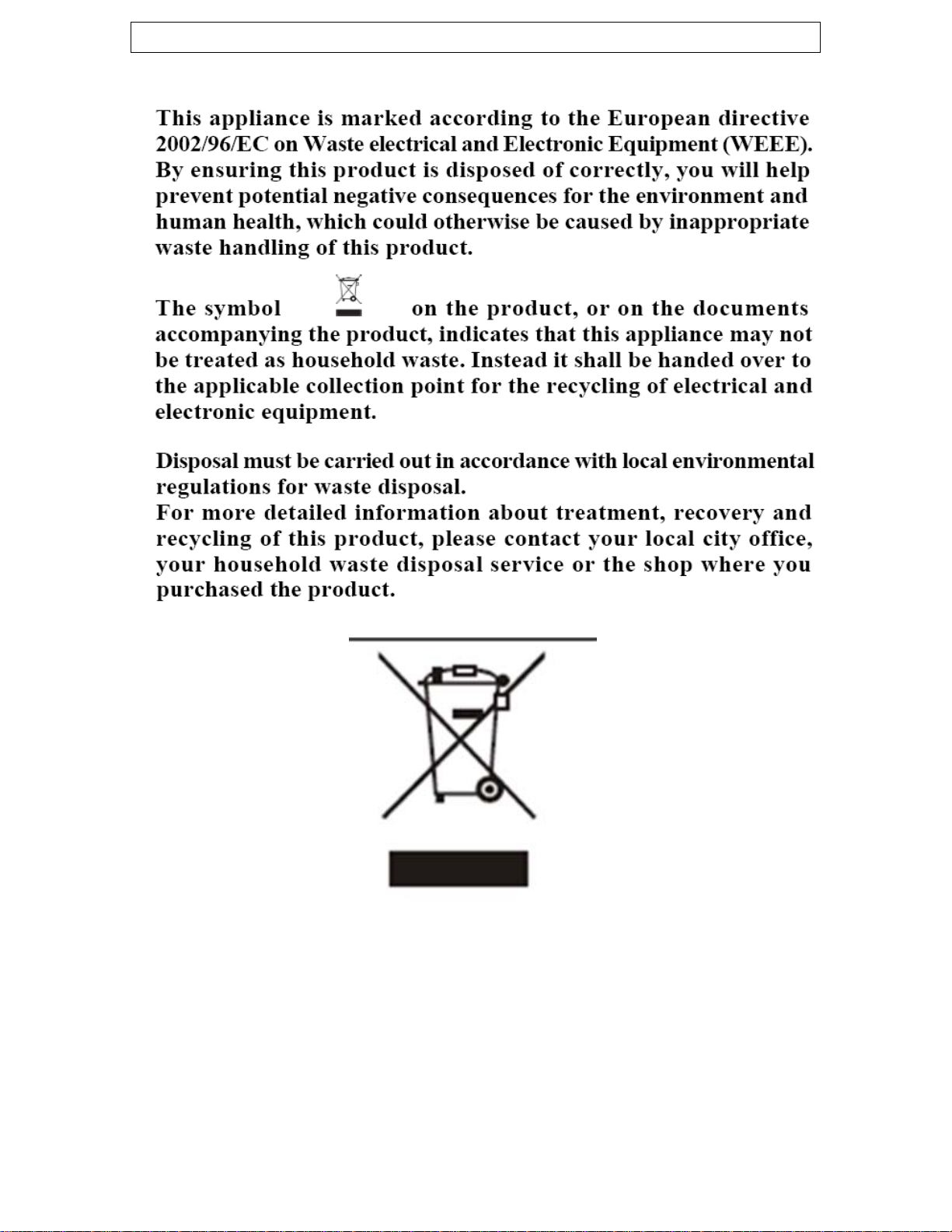
Declaration of conformity
This appliance complies with the following European Directives:
-73/23/EEC regarding “low voltage”
-89/336/EEC regarding “electromagnetic disturbances”
-90/396/EEC regarding “gas appliances”
-89/109/EEC regarding “materials in contact with food”.
o The above directives comply with 93/68/EEC regarding CE
marking.
o The manufacturer declares that the oven is built using certified
materials and requires the appliance to be installed in
accordance with the standards currently in force. This appliance
must be used by a trained person for domestic purposes only.
8
Page 9
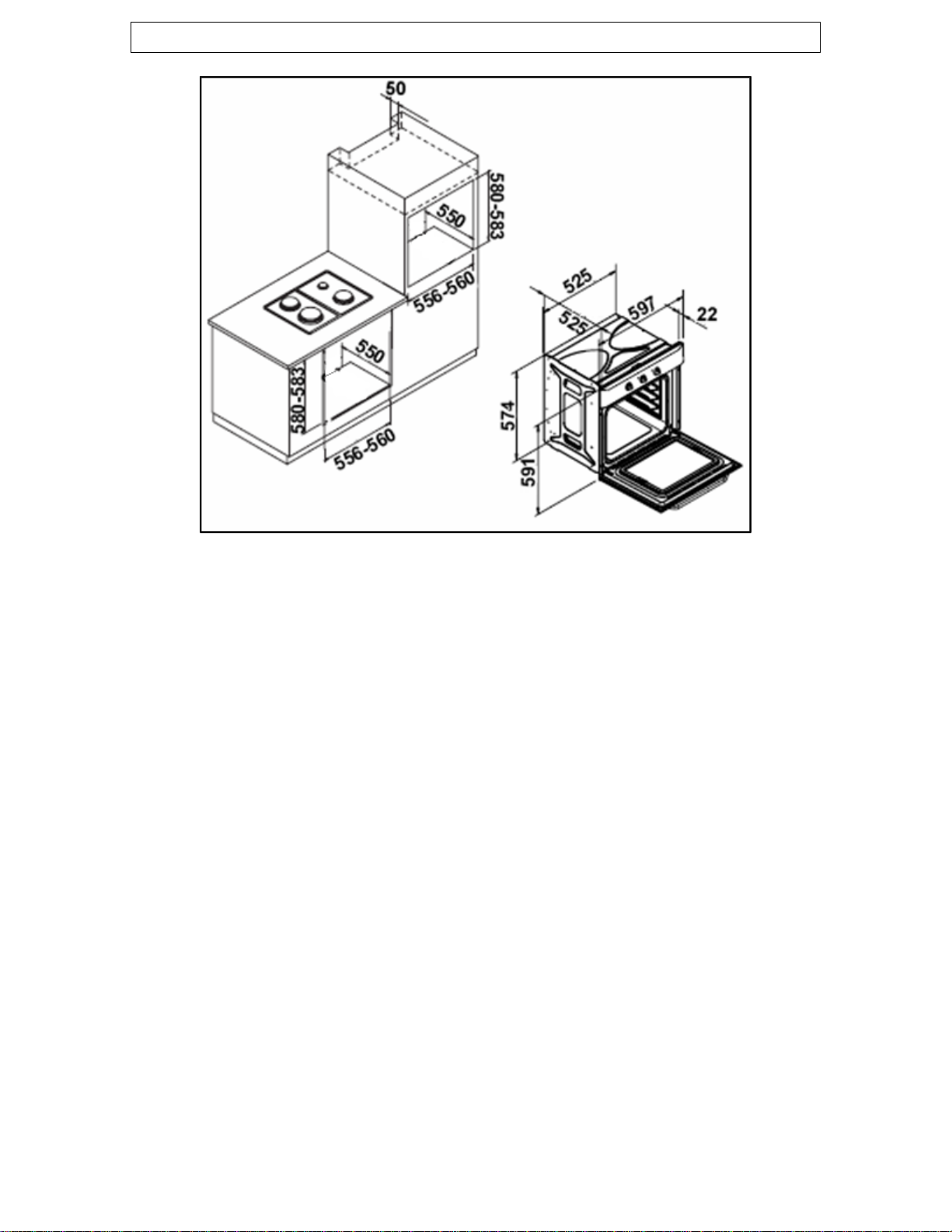
Specifications
(IMPORTANT: The above drawing does not show the ventilation
requirements that are necessary for installing this appliance, please
refer to the installation instructions for this information).
Product Dimensions Aperture Dimensions
Height: 591 mm 580 mm – 583 mm
Width: 597 mm 556 mm - 560 mm
Depth: 525 mm 550 mm
Cooling fan
o A tangential cooling fan is fitted inside of this appliance, to make
the internal temperature of the oven stable and the external
surface temperature lower.
Product specifications
o Oven capacity: 47 litres
o Minute minder
o LED minute minder (B609.1SS only)
o Cooling fan
o Gas grill
o Flame failure safety device
o Auto-ignition
o Fan-assisted gas oven with lower burner
o Double-glazed removable door
9
Page 10

Standard accessories
o Removable side racks
o 2 x safety shelves
o Enamelled drip tray with handle
o Trivet
o LPG conversion jets
Optional extras
o BPS1 Pizza stone
Electrical details
Rated Voltage: 230 Vac 50 Hz
Supply Connection: 13 A (double pole switched fused
outlet with 3mm contact gap)
Fuse rating: 3 amp
Max Rated Inputs: 0.075 kW
Mains Supply Lead: 3 x 1.0 mm²
For future reference please record the following information which can
be found on the Rating Plate and the date of purchase which can be
found on your sales invoice. The rating plate for your oven can be
located by opening the oven door and looking on the right hand side of
the oven chassis.
Model Number ……………………………….
Serial Number ……………………………….
Date of Purchase ……………………………….
10
Page 11
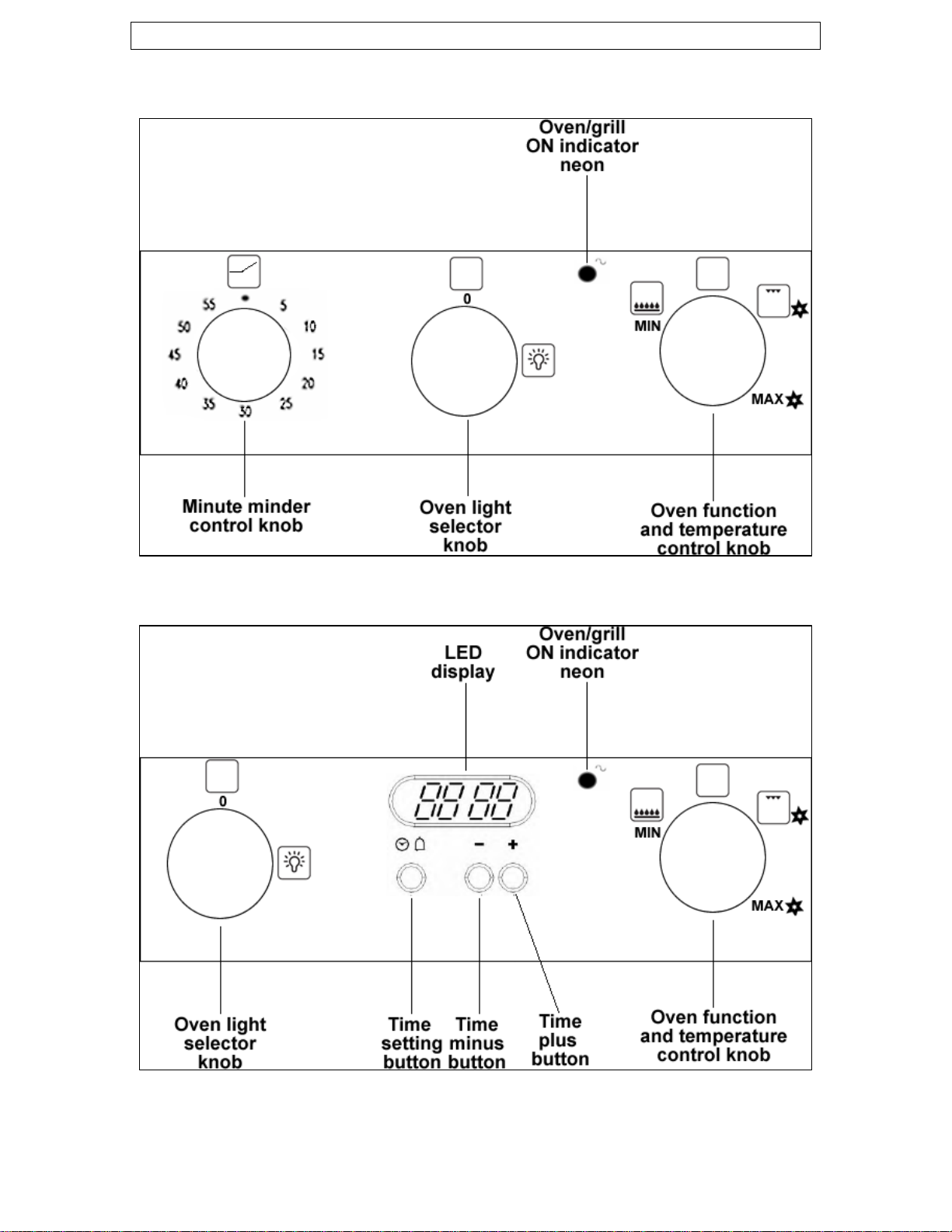
Control Panel
B602.1/B604.1
B609.1
11
Page 12

Before first use
o To remove any residue from the oven that may have been left
from the manufacturing process, you should select the gas oven
and set it to its maximum temperature setting.
o It is perfectly normal for a smell to be produced during this
process.
o You should make sure that any windows in the room are left
open during this process.
o It is advisable for you not to remain in the room whilst the
burning off process is taking place.
o You should leave the oven on maximum setting for 30 – 40
minutes.
Setting the time of day (B609.1SS only)
When the oven is switched on for the first time (or if power has been
cut to the appliance), three zeros will flash on the timer display.
o To set the time of day, hold down button (A) and then press the
(B) and (C) buttons until the current time of day is shown on
the timer display.
o The speed that the time adjusts at depends on how hard the (B)
and (C) buttons are held down.
o When the correct time of day is shown, release all of the
buttons. After a few seconds the time of day will be set on the
timer display.
12
Page 13

Switching the gas oven on
The oven has electric ignition, to light it you should do the following:-
o Open the door of the appliance.
o Push the oven function and temperature control knob down
slightly and then turn it anticlockwise to the word MAX.
o Whilst it is pointed to the MAX position, fully push down this
knob and hold it down.
o The gas oven should light within 15 seconds.
o Once the burner has lit, continue to keep the oven function and
temperature control knob held down for a further 10 seconds.
Otherwise the safety cut off will operate and block the flow of
gas.
o IMPORTANT: When you are certain that the oven burner is fully
lit, close the oven door. Then turn the oven function and
temperature control knob clockwise until it reaches the
temperature that you desire.
o DO NOT turn the control knob past the MIN position, otherwise
the burner may go out.
o If the gas oven does not light within 15 seconds, then release
the oven function and temperature control knob. IMPORTANT:
YOU MUST TURN THE CONTROL KNOB BACK TO ITS
ORIGINAL POSITION; OTHERWISE GAS WILL CONTINUE
TO BE RELEASED.
o Wait for 1 minute, before repeating the ignition procedure again.
When lighting your oven for the first time, it may take
several times until the electric ignition operates. This is
due to air being in the gas pipe.
13
Page 14

Switching the gas grill on
The grill has electric ignition, to light it you should do the following:-
o Open the door of the oven and fit the
grill defllector to the front of the
appliance.
o Push the oven function and
temperature control knob down slightly
and then turn it anticlockwise to the
grill symbol (shown above)
o Whilst it is pointed to the grill symbol, fully push down this knob
and hold it down.
o The gas grill should light within 15 seconds.
o Once the burner has lit, continue to keep the oven function and
temperature control knob held down for a further 10 seconds.
Otherwise the safety cut off will operate and block the flow of
gas.
o THE OVEN DOOR MUST BE LEFT OPEN WHILST YOU ARE
GRILLING.
o If the gas grill does not light within 15 seconds, then release the
oven function and temperature control knob. IMPORTANT: YOU
MUST TURN THE CONTROL KNOB BACK TO ITS ORIGINAL
POSITION; OTHERWISE GAS WILL CONTINUE TO BE
RELEASED.
o Wait for 1 minute, before repeating the ignition procedure again.
When lighting your grill for the first time, it may take
several times until the electric ignition operates. This is
due to air being in the gas pipe.
o IMPORTANT: You should allow the oven to cool completely
before attempting to remove the grill deflector. If you
attempt to remove the grill deflector before the oven is
cool, it will be hot.
14
Page 15

Operation of the fan
o After igniting the oven and shutting the door of the appliance,
check to make sure that the fan on the rear wall of the oven
cavity is turning.
o IMPORTANT: If there is a power cut whilst the oven is in use,
then you should immediately turn the oven off until power is
restored.
o If the cooling fan does not operate and there is still power to the
appliance, then DO NOT continue to use the appliance. Switch
the oven off and contact the Baumatic Service Department to
arrange for an engineer to attend the appliance.
If the oven is in use and the door is opened, the cooling
fan will stop operating. This is to prevent excessive heat
being blown in the direction of the user. When the door is
shut again, check to make sure that the fan restarts.
Cooking guidelines
o Please refer to the information given on food packaging for
guidance on cooking temperatures and times. Once familiar with
the performance of your appliance, temperatures and times can
be varied to suit personal preference.
o Make sure that frozen foods are thoroughly thawed before
cooking, unless the instructions on the food packaging advise
that you can “cook from frozen”.
o Before cooking, check that any unused accessories are removed
from the oven.
o Place cooking trays in the centre of the oven and leave gaps
between the trays to allow air to circulate.
o Try to open the door as little as possible to view the dishes.
15
Page 16

Warnings
o Keep the oven door open when using the grill function and make
sure that the grill deflector is fitted.
o Do not use aluminium foil to cover the grill pan or heat items
wrapped in aluminium foil under the grill. The high reflectivity of
the foil could potentially damage the grill element.
o You should also never line the base of your oven with aluminium
foil.
o During cooking, never place pans or cookware directly onto the
bottom of your oven. They should always be placed on the
shelves provided.
o The grill heating element becomes extremely hot during
operation, avoid touching it inadvertently when handling the
food which you are grilling.
o Important: Be careful when opening the door, to avoid contact
with hot parts and steam.
o The drip tray handle should only be used to reposition the drip
tray and NOT for removing it from the oven cavity. When
removing the drip tray, you should ALWAYS use an oven glove.
o The drip tray handle should not be left in position when the
appliance is switched on.
16
Page 17

Setting a countdown time (B609.1SS only)
o Press button (C) and the numbers on the timer display will begin
to advance and a symbol will illuminate.
o Use buttons (B) and (C) to adjust the time on the timer display,
until it shows the length of time that you want the oven to
countdown for.
o The maximum countdown time that can be set is 99 minutes and
59 seconds.
o Once your desired countdown time is displayed, release all of the
buttons. After 10 seconds, the countdown time will be stored and
the countdown will commence immediately.
o At the end of the cooking time a bell will ring for 7 minutes. It
can be switched off by pressing button (C) once.
o To reset a countdown before it reaches its end time, press
buttons (B) and (C) simultaneously. Then release button (C)
first, followed by button (B).
IMPORTANT: If you have the oven or grill in use
whilst the timer is counting down. When the
countdown ends, the oven will continue to heat. You
must turn off the oven/grill using the oven function
and temperature control knob.
Adjusting the audible signal (B609.1SS only)
There are 3 levels of audible signal available; to adjust it you should
do the following:
o When the time of day is shown on the timer display, press
button (B) for approximately 2 seconds. You will then hear the
current level of audible signal.
o Repeat this process until the audible signal reaches the level that
you require, and then release the button (B).
17
Page 18

Using the minute minder (B602.1 & B604.1)
The minute minder can be used independently of
an oven cooking function for a time period of up
to 60 minutes.
o To set the timer, turn the knob fully clockwise until it stops and
then turn it back anticlockwise to the required time.
o The time period that has been set will expire when the control
knob reaches zero, a brief audible signal will sound.
IMPORTANT: If you have the oven or grill in use
whilst the timer is counting down. When the
countdown ends, the oven will continue to heat. You
must turn off the oven/grill using the oven function
and temperature control knob.
The oven light
o Turn the oven light selector knob clockwise, until it reaches the
light bulb symbol.
o The oven light can be turned on, regardless of whether the
oven/grill are in use.
18
Page 19

Cleaning and maintenance
Cleaning operations must only be carried out
when the oven is cool.
The appliance should be disconnected from your
mains supply before commencing any cleaning
process.
o The oven should be thoroughly cleaned before it is operated for
the first time and after each use. This will avoid residual food
stuffs becoming baked on the oven cavity. After residues have
been baked on several times, they are far more difficult to
remove.
o Never clean the oven surfaces by steam cleaning.
o The oven cavity should only be cleaned with warm soapy water,
using either a sponge or soft cloth. No abrasive cleaners should
be used.
o Any stains that may appear on the bottom of the oven will have
originated from food splashes or spilt food, these splashes occur
during the cooking process. These could possibly be a result of
the food being cooked at an excessively high temperature or
being placed in cookware that is too small.
o You should make sure that the cooking temperature that is
selected is appropriate for the food that you are cooking. You
should also ensure that the food is placed in an adequately sized
dish and that you use the drip tray where appropriate.
o Outer parts of the oven should only be cleaned with warm soapy
water, using either a sponge or soft cloth. No abrasive cleaners
should be used.
o If you use any form of oven cleaner on your appliance, then you
must check with the manufacturer of the cleaner that it is
suitable for use on your appliance.
o Any damage that is caused to the appliance by a cleaning
product will not be fixed by Baumatic free of charge, even
if the appliance is within the guarantee period.
19
Page 20

Replacing the oven bulb
IMPORTANT: The oven must be disconnected from
your mains supply before you attempt to either
remove or replace the oven bulb.
o Remove all oven shelves and the drip tray to make it easier to
access the bulb.
o Remove the light cover by turning it anti-clockwise.
o Unscrew the bulb clockwise and remove it from its holder.
o Replace the bulb with a 25 W/300°C, screw type pigmy.
o Do not use any other type of bulb.
o Place the lamp cover back into position.
20
Page 21

Removing the oven door for cleaning
To facilitate the cleaning of the inside of the oven and the outer frame
of the oven, the door can be removed as follows:-
o The hinges (A) have two movable bolts on them (B).
o If you raise both of the movable bolts (B), then the hinges (A)
are released from the oven housing.
o You should grip the sides of the door at the centre and then
incline it slightly towards the oven cavity and then by pulling it
gently away from the oven cavity.
o IMPORTANT: You should make sure that the door is supported
at all times and that you place the door on some padded
material whilst cleaning it.
o The oven door and door glass should only be cleaned using a
damp cloth and a small amount of detergent. The cloth MUST
NOT have come into contact with any form of cleaning product
or chemical previously.
o To refit the door you should slide the hinges back into their slots
and open the door fully.
o IMPORTANT: The movable bolts (B) must be closed back into
their original positions before closing the door.
o Take care not to dislodge the hinge locking
system when removing the door, as the
hinge mechanism has a strong spring.
o Do not immerse the door in water at any
time.
21
Page 22

Removing the inner door glass for cleaning
o Do not use any abrasive cleaner that could cause damage.
o Remember that if the surface of the glass panel becomes
scratched, this could lead to a dangerous failure.
o To facilitate cleaning, the door glass can be lifted out after
removing the fixing screws and turning the metal stoppers that
hold the glass in position.
o When refitting, make sure that the glass is correctly seated in
the door recess and the correct way round, before turning the
metal stoppers back to their original position and fully tightening
the fixing screws.
Installation
The installation must be carried out by a suitably
qualified person, in accordance with the current
version of the following.
o UK Regulations and Safety Standards or their European
Norm Replacements.
o Building Regulations (issued by the Department of the
Environment).
o Building Standards (issued by the Scottish Development
Department).
o IEE Wiring Regulations.
o Electricity At Work Regulations.
o Gas Safety (Installation and Use) (Amendment)
Regulations.
WARNING: THIS APPLIANCE MUST BE EARTHED.
o This appliance should be wired into a 13 A double pole switched
fused spur outlet, having 3 mm contact separation and the fuse
rating reduced to 3 amps. This should be placed in an easily
accessible position adjacent to the appliance, preferably above
worktop level. An outlet can then be located at the rear of the
appliance for connection.
22
Page 23

o To connect the oven power cord, loosen and remove the cover
on the terminal block, in order to gain access to the contacts
inside. Make the connection, securing the cord in place with the
cable clamp provided and then immediately close the terminal
block cover again.
o If you have to change the oven power cord, the earthing
(yellow/green) conductor must always be 10 mm longer than the
line conductors.
o Care must be taken to ensure that the temperature of the mains
supply cable does not exceed 50°C.
o If the mains supply cable is damaged, then it must be replaced
by an appropriate replacement.
Positioning
The adjacent furniture and all materials used in the
installation must be able to withstand a minimum
temperature of 85°C above the ambient
temperature of the room it is located in, whilst the
appliance is in use.
o Your appliance is heavy, so you should be careful when moving
or positioning it.
o Do not try to move the cooker by pulling on either the door,
handle or control panel.
o The oven may be located in a kitchen, or a bedroom, but not in a
room containing a bath or shower. The oven must not be
installed in a bedroom of less than 20m³ in size.
o LPG models must not be installed in a room or internal space
below ground level (e.g. in a basement).
o This oven may be used for a built-in or built under installation
(see the diagrams on pages 25 - 26).
23
Page 24

Installing the oven into the kitchen cabinet
Positioning the appliance
o Ensure that the aperture that you will be fitting the oven into is
of the size given in the above diagram.
o The oven must be fitted into an oven housing with the ventilation
cut-outs shown in the “Ventilation requirements” section on the
next page.
o Ensure that the rear panel of the furniture housing unit has been
removed.
24
Page 25

Ventilation requirements
o You should remove the rear panel of the housing unit before
attempting to install the oven. A full depth shelf must be
incorporated into the housing and positioned 50 mm below the
support shelf for the appliance.
o A minimum ventilation gap of 90 mm must be allowed between
the rear of the support shelf and the rear of the housing unit.
o A 400 cm² (20 x 20 cm) ventilation cut out must be made in the
support shelf.
o A minimum ventilation area of 80 cm² must be allowed below
the appliance.
o If the appliance is to be installed in a Leisure Accommodation
Vehicle, the requirements of EN 721 must be applied.
25
Page 26

Additional built under ventilation requirements
o Remove the horizontal strengthening support at the upper front
housing unit.
o If your housing unit incorporates a domestic lower drawer, this
must be made non-functioning with a ventilated false front.
o A 5 mm ventilation gap must be allowed between the top of the
appliance and the underside of the worktop.
Additional tall housing ventilation requirements
o A 500 x 15 mm cut out must be made in the top of the housing
unit, the plinth and any other additional shelves apart from the
support shelf.
o If the unit is fitted flush with the kitchen ceiling, a 20 cm²
ventilation cut out must be made in the top front of the housing.
o For both times of
installation, ensure that the
oven has been securely fixed
into the housing unit. The
fixing of the oven into the
housing is made by using
four screws. These should be
screwed through the oven
cabinet and into the housing
unit.
26
Page 27

Gas connection
This appliance must be installed by a competent
person in accordance with the current versions of
the following UK (United Kingdom) or ROI (Republic
of Ireland) Regulations and Safety Standards or
their European Norm Replaceme
Important information
o This oven is supplied to run on natural gas only and cannot be
used on any other type of gas without modification.
o Conversion for use on LPG and other gases must only be
undertaken by a qualified person. For information on the use of
other gases, please contact the Baumatic Technical Department.
o The oven must be installed by a qualified person, in accordance
with the current edition of the Gas Safety (Installation and Use)
Regulations and the relevant building/I.E.E. Regulations.
o Failure to install the appliance correctly could invalidate
Baumatic’s guarantee and lead to prosecution under the
regulations quoted above.
o In the UK, only CORGI registered installers are authorised to
undertake the installation and service work, in compliance with
the above regulations.
Ventilation requirements
o The room containing the oven should have an air supply in
accordance with the current edition of BS 5440: Part 2:
o The room must have opening windows or equivalent; some
rooms may also require a permanent vent.
o If the room has a volume between 5 and 10m³, it will require an
air vent of 50cm² (effective area). Unless it has a door which
opens directly to the outside.
o If the room has a volume of less than 5m³, it will require an air
vent of 100cm² (effective area).
o If there are any other fuel burning appliances in the same room
the current edition of BS 5440: Part 2: should be consulted to
determine air vent requirements.
nts.
27
Page 28

o Ensure that the room containing the oven is well ventilated, keep
natural ventilation holes.
o Prolonged intensive use of the appliance may call for additional
ventilation.
o This oven is not fitted with a device for discharging the products
of combustion. Ensure that the ventilation rules and regulations
are followed.
o Your oven must stand on a flat surface so that when it is in
position the oven is level. When in position check that the oven
is level by using a spirit level.
o Remember that the quantity of air necessary for combustion
must never be less than 2m³/h for each kW of power (see total
power in kW on the appliance rating plate).
Gas Safety (Installation and Use) Regulations
o It is a legal requirement that all gas appliances are installed by
competent persons in accordance with the current edition of the
Gas Safety Installation and Use Regulations.
o For reasons of safety, it is in your best interests to ensure
compliance with the law.
o In the UK, CORGI registered installers work to safe standards of
practice. The cooker must also be installed in accordance with
the current edition of BS 6172. Failure to install the oven
correctly could invalidate the warranty, liability claims and lead
to prosecution.
28
Page 29

Gas connection
ALL INSTALLATION AND SERVICE WORK MUST BE
CARRIED OUT BY A CORGI REGISTERED ENGINEER.
o Prior to installation, ensure that the gas supply conditions
(nature of the gas and gas pressure) and the adjustment
conditions are compatible. The adjustment conditions for this
appliance are stated on the rating plate which can be found on
the back cover.
o This appliance is not designed to be connected to a combustion
product evacuation device. Particular attention should be given
to the relevant requirements regarding ventilation.
o A ½” BSP female to female gas
elbow (not supplied) should be
connected to the gas inlet at the
rear of the appliance and
pointing in a downward direc
As indicated in the diagra
opposite.
o IMPORTANT: FIBRE WASHERS MUST BE USED WHEN
CONNECTING THE GAS ELBOW (AS SHOWN IN THE ABOVE
DIAGRAM).
o Connection to the cooker should be made with an approved
appliance flexible connection to BS 669.
o If the cooker has been converted for use with LPG, then it should
be connected to the gas supply using an appropriate bayonet
type hose. The hose MUST be suitable for use with LPG gas,
these are identifiable by a red band or stripe.
o A hose length of 0.9m to 1.25m is recommended. The length of
hose chosen should be such that when the cooker is in situ, the
hose does not touch the floor.
o Care should be taken to ensure that the temperature rise of
areas at the rear of the cooker that are likely to come in contact
with the flexible hose do not exceed 70°C.
o IMPORTANT: On completion carry out a gas tightness test.
m
tion.
29
Page 30

Gas adjustment (Conversion to LPG and gas adjustment)
IMPORTANT: Your appliance must be disconnected from the
electric and gas supply before completing this process.
Power inputs
Natural Gas LPG
Oven 2.74 kW (injector size 115) 2.74 kW (injector size 80)
Grill 2.4 kW (injector size 115) 2.4 kW (injector size 80)
Gas details
Gas Connection Type: 1/2” BSP male thread
Gas Type (Natural Gas G20): 20 mbar
Primary air gap (Natural Gas G20): 1.0 mm
Gas Type (LPG G30/31): 28/37 mbar
Primary air gap (LPG G30/31): 1.0 mm
o Remove the rear wall assembly
and the oven burner assembly.
o Replace the injector with one
suitable for LPG (see power
inputs information). It is
recommended that the
appropriate thread sealant is
used; always check for gas
tightness after assembly.
o Re-fix the burner
assembly, ensuring that
the injector is within the
cut-out in the rear of the
oven. Adjust the position
of the burner to achieve
the primary air gap.
30
Page 31

o Remove the grill burner.
o Replace the injector with one
suitable for LPG (see power
inputs information). It is
recommended that the
appropriate thread sealant is
used; always check for gas
tightness after assembly.
o Re-fix the grill burner, no further adjustments are necessary.
o Remove the control
panel cover from the
top of the appliance.
o Remove the oven
control knobs and
then undo the two
fixing rings that are
exposed underneath,
by turning them anticlockwise.
o Disconnect the neon lamp at the rear of the fascia and then
remove the control panel front. Then refit the thermostat control
knob.
o Ensure that the appliance is in a safe condition, and then
reconnect it to the electric and gas supply.
o Open the oven door fully and ignite the oven burner. You should
set the oven to maximum temperature, then close the oven door
and leave the appliance for 10 – 15 minutes.
o Reduce the temperature to its minimum setting and remove the
thermostat control knob.
o DISCONNECT THE APPLIANCE FROM THE ELECTRICITY
SUPPLY.
o The bypass adjustment screw is located on the left hand side of
the valve body. Access can be made from the front of the
appliance and through the rear panel of the control panel. Turn
the screw clockwise to decrease the flow.
31
Page 32

o Adjust the bypass setting until the correct flame picture is
achieved.
o Refit the control knob, then turn it to the Max position and then
back to Min several times, checking that the flame is maintained.
o Fully open and close the oven door several times and check that
the flame is maintained.
o Turn the appliance off and disconnect it from the gas supply.
o Re-assemble the appliance (including the refitting of the rear
wall assembly), reinstall it and then carry out a full function test
(this should include a gas tightness test).
My appliance isn’t working correctly
The gas oven burner or grill burner do not light.
* Check that the oven is switched on at your mains supply.
* Check that the fuse in the spur outlet doesn’t need replacing.
* Check that there is not a problem with your gas supply
Food is cooking too quickly or too slowly.
* Check that you are cooking at an appropriate temperature and
shelf level.
The oven is not cooking evenly.
* Check that the oven is installed correctly.
* Check that you are cooking at an appropriate temperature and
shelf level.
The oven light does not work.
* Follow the “Replacing the oven bulb” section on page 20.
32
Page 33

I am getting condensation in my oven
* Steam and condensation is a natural by product of cooking any
food with high water content, such as frozen food, chicken etc.
* You may get condensation in the oven cavity and forming
between the oven door glasses. This is not necessarily a sign
that the oven is not working correctly.
* Do not leave food in the oven to cool after it has been cooked
and the oven has been switched off.
* Use a covered container, where practical, when cooking to
reduce the amount of condensation that forms.
IMPORTANT: If your appliance appears not to be
operating correctly, then you should disconnect it
from your mains supply and then contact the
Baumatic Service Department on telephone
number (0118) 933 6911.
DO NOT ATTEMPT TO REPAIR THE APPLIANCE
YOURSELF.
Please note that if an engineer is asked to attend whilst the product is
under guarantee and finds that the problem is not the result of an
appliance fault, then you may be liable for the cost of the call out
charge.
The appliance must be accessible for the engineer to perform
any necessary repair. If your appliance is installed in such a
way that an engineer is concerned that damage will be caused
to the appliance or your kitchen, then he will not complete a
repair.
This includes situations where appliances have been tiled in,
sealed in with sealant, have wooden obstructions placed in
front of the appliance, like plinths. Or any installation other
than the one specified by Baumatic Ltd. has been completed.
Please refer to the conditions of guarantee that appear on the
warranty card that you receive with the appliance.
33
Page 34

United Kingdom
Baumatic Ltd.,
Baumatic Buildings,
6 Bennet Road,
Reading, Berkshire
RG2 0QX
United Kingdom
Sales Telephone
(0118) 933 6900
Sales Fax
(0118) 931 0035
Service Telephone
(0118) 933 6911
Service Fax
(0118) 986 9124
Spares Telephone
(01235) 437244
Technical Advice Telephone
(0118) 933 6933
E-mail:
sales@baumatic.co.uk
technical@baumatic.co.uk
Website:
www.baumatic.co.uk
Republic of Ireland
01- 6266 798
Czech Republic
Baumatic CR spol s.r.o.
Amperova 495
46215, Librec
Czech Republic
+420 800 185 263
www.baumatic.cz
Slovak Republic
Baumatic Slovakia, s.r.o.
Skultetyho 1
831 04 Bratislava 3
Slovakia
+421 255 640 618
Germany
Baumatic Gmbh
Janderstrasse 9
Mannheim, 68199
Germany
+4962 112 9190
www.baumatic.de
Italy
Baumatic Italia S.R.L.
Via Caltana 129
Campodarsego (Padova), 35011
Italy
+3904 9920 2297
www.baumatic.it
Holland
Baumatic Benelux B.V.
Grindzuigerstraat 22
1333 MS ALMERE
The Netherlands
+3136 549 1555
www.baumatic.nl
34
Page 35

35
Page 36

36
 Loading...