


Page 1
D
Gebrauchs- und Montageanweisung
Induktions-Glaskeramik-Kochfeld
GB
F
I
NL
Instructions for fi tting and use
Glass ceramic induction hob
Instructions de montage et d’utilisation
Table de cuisson vitrocéramique à induction
Istruzioni per uso e montaggio
Piano di cottura ad induzione in vetroceramica
Gebruiks- en montageaanwijzing
Keramische inductiekookplaat
CTDI K 840C NE
Page 2

Inhalt
D
1 Sicherheits- und Warnhinweise .................................3
2 Montageanleitung ........................................................6
2.1 Sicherheitshinweise für den Küchenmöbelmonteur6
2.2 Belüftung ..................................................................6
2.3 Einbau ......................................................................6
2.4 Variable Einbaumöglichkeit: aufl iegender Einbau ...7
2.5 Variable Einbaumöglichkeit:
fl ächenbündiger Einbau ...........................................7
2.6 Abbildungen Küchenschrank ...................................8
2.7 Zusammenbau Abluftsystem ...................................9
2.8 Wichtige Hinweise zum Einbau
des Kochmuldenlüfters ..........................................10
2.9 7-poliger Stecker Anschluss Lüfter ........................11
2.10 4-poliger Stecker Anschluss
Plasmafi lter (optional) ..........................................11
2.11 Einbau Kochmulden Lüfter ..................................12
2.12 Technische Daten ................................................13
2.13 Inbetriebnahme ....................................................13
3 Gerätebeschreibung ..................................................14
3.1 Bedienung durch Sensortasten .............................15
4 Bedienung ...................................................................16
4.1 Das Induktionskochfeld..........................................16
4.2 Topferkennung ......................................................16
4.3 Betriebsdauerbegrenzung .....................................16
4.4 Sonstige Funktionen ..............................................16
4.5 Überhitzungsschutz (Induktion) .............................16
4.6 Geschirr für Induktionskochfeld .............................17
4.7 Energiespartipps ....................................................17
4.8 Kochstufen .............................................................17
4.9 Restwärmeanzeige ...............................................17
4.10 Gerät betriebsbereit schalten ..............................18
4.11 Tastenbetätigung ..................................................18
4.12 Kochfeld und Kochzone einschalten ...................18
4.13 Kochzone ausschalten ........................................18
4.14 Kochfeld abschalten ............................................18
4.15 Verriegelung .........................................................19
4.16 Abschaltautomatik (Timer) ..................................20
4.17 Kurzzeitwecker (Eier-Uhr) ...................................20
4.18 Powerstufe ...........................................................21
4.19 Brückenfunktion ..................................................21
4.20 Powermanagement .............................................21
4.21 Lüfter verwenden .................................................22
4.21.1 Lüfter ein- und ausschalten ..............................22
4.21.2 Lüfternachlauf ...................................................22
4.21.3 Nachlaufzeit .....................................................22
5 Reinigung und Pfl ege ................................................23
5.1 Glaskeramik-Kochfeld............................................23
5.2 Spezielle Verschmutzungen ..................................23
5.3 Kochmulden Lüfter .................................................23
6 Was tun bei Problemen? ...........................................24
7 Kundendienst .............................................................25
VIELEN DANK, DASS SIE EIN GERÄT VON
BAUKNECHT GEKAUFT HABEN
Für einen umfassenderen Kundenservice, registrieren Sie
Ihr Produkt bitte unter www.bauknecht.eu/
Lesen Sie unbedingt die Sicherheitshinweise vor der Inbetriebnahme Ihres Gerätes
2
Page 3
Sicherheits- und Warnhinweise
D
1 Sicherheits- und Warnhinweise
WICHTIG
Lesen und laden Sie die komplette Anleitung
unter docs.bauknecht.eu runter oder rufen
Sie die in der Garantieerklärung aufgeführte
Telefonnummer an.
Bitte lesen Sie die Informationen in diesem
Heft sorgfältig durch, bevor Sie Ihr Kochfeld in
Betrieb nehmen und halten Sie sie für späteren Gebrauch bereit.
Beachten Sie immer alle Sicherheitshinweise
in dieser Anleitung und am Gerät selber. Der
Hersteller kann nicht für Schäden verantwortlich gemacht werden, die durch Fehler bei der
Benutzung, Nichtbeachtung der Sicherheitshinweise und fehlerhafte Einstellungen verursacht werden
Kleinkinder unter 3 Jahren dürfen sich nicht
unbeaufsichtigt in der Nähe des Geräts aufhalten. Kinder unter 8 Jahren sollten vom
Gerät ferngehalten werden, es sei denn sie
werden durchgängig beaufsichtigt. Dieses Gerät ist nicht dafür bestimmt, durch Personen
(einschließlich Kinder ab 8 Jahren) mit eingeschränkten physischen, sensorischen oder
geistigen Fähigkeiten oder mangels Erfahrung
und/oder mangels Wissen benutzt zu werden,
es sei denn, sie werden durch eine für ihre
Sicherheit zuständige Person beaufsichtigt
oder erhielten von ihr Anweisungen, wie das
Gerät zu benutzen ist. Achten Sie darauf,
dass Kinder nicht mit dem Gerät spielen können. Halten Sie während der Reinigungs- und
Wartungsarbeiten Kinder vom Gerät fern.
ACHTUNG: Zugängliche Geräteteile erwärmen sich während des Gebrauchs sehr stark.
Achten Sie darauf, heiße Teile nicht zu berühren. Kinder unter 8 Jahren sollten vom Gerät
ferngehalten werden, es sei denn sie werden
durchgängig beaufsichtigt.
VORSICHT: Zugängliche Geräteteile der
Kochmulde erwärmen sich während des Gebrauchs.
ACHTUNG: Bei Brüchen, Sprüngen, Rissen
oder anderen Beschädigungen an der Glasfl äche besteht bei Gebrauch Stromschlaggefahr.
ACHTUNG: Feuergefahr! Die Kochzonen
dürfen nicht als Ablagefl äche benutzt werden.
VORSICHT: Beaufsichtigen Sie ständig jeden
kurzen oder längeren Kochvorgang.
ACHTUNG: Bereiten Sie Speisen mit Fett
oder Öl immer unter Aufsicht zu – Feuergefahr. Brennendes Öl / Fett NIE mit Wasser
löschen! Schalten Sie das Gerät aus und
bedecken die Flamme mit einer Decke, einem
Topfdeckel oder ein Löschdecke.
Töpfe mit Frittierfett oder Öl niemals unbeaufsichtigt lassen, brennendes Öl kann sich
entzünden.
Das Kochfeld niemals als Ablage- oder Standfl äche verwenden! Brennbare Materialien,
z.B. Kleidung solange vom Gerät fernhalten,
bis die Kochzonen komplett abgekühlt sind –
FEUERGEFAHR.
Gegenstände aus Metall, wie z.B. Messer,
Gabel, Löff el und Deckel sollten nicht auf der
Kochfl äche abgelegt werden, da sie heiß werden können.
Schalten Sie eine Kochzone nach Gebrauch
unbedingt durch die Steuerung ab und nicht
allein durch die Topferkennung.
BESTIMMUNGSGEMÄSSE VERWENDUNG
VORSICHT: Das Gerät darf nicht über externe Schaltgeräte, wie z.B. Timer oder separate
Fernbedienung bedient werden.
Dieses Gerät ist für den Haushaltsbedarf und
für die Nutzung anderen, ähnlichen Einrichtungen, bestimmt, wie z.B. Mitarbeiterküchen
in Geschäften, Büros und anderen Arbeitsumgebungen, in landwirtschaftlichen Betrieben
und durch Kunden in Hotels, Motels, Frühstückspensionen und weiteren typischen
Wohnumgebungen.
Dieses Gerät ist nicht für die professionelle
Nutzung bestimmt. Betreiben Sie das Gerät
nicht im Freien.
3
Page 4

Sicherheits- und Warnhinweise
D
INSTALLATION
Das Gerät muss immer von mindestens zwei
Personen bewegt und eingebaut werden Unfallgefahr!. Tragen Sie beim Auspacken und
Einbau Schutzhandschuhe zur Vermeidung von
Schnittverletzungen.
Der Einbau, einschließlich des Wasseranschlusses (falls notwendig) darf nur von einem
qualifi zierten Techniker durchgeführt werden.
Reparieren oder ersetzen Sie keine Geräteteile, außer wenn dies ausdrücklich in der Gebrauchsanweisung beschrieben sein sollte.
Halten Sie Kinder fern vom Einbauort.
Nachdem Sie das Gerät aus der Verpackung
genommen haben, kontrollieren Sie es auf
eventuelle Transportbeschädigungen. Bei
Problemen wenden Sie sich an Ihren Händler
oder nächsten Kundendienst. Entfernen Sie
nach dem Einbau alle Verpackungsabfälle
(Plastik, Schaumstoff teile etc.) aus der Reichweite von Kindern - Erstickungsgefahr. Trennen
Sie vor dem Einbau das Gerät von der Stromversorgung - Stromschlaggefahr. Stellen Sie
beim Einbau sicher, dass das Netzkabel nicht
beschädigt wird - Feuer- und Stromschlaggefahr. Schalten Sie das Gerät nur ein, wenn der
Einbau vollständig abgeschlossen ist.
Alle Ausschnittarbeiten an Möbel und Arbeitsplatte vor dem Einsetzen der Geräte durchführen und die Späne entfernen.
Wenn das Gerät NICHT über einem Ofen eingebaut wird, muss eine Trennwand (nicht im
Lieferumfang enthalten) in das Küchenmöbel
unter dem Gerät eingebaut werden.
Bei gleichzeitigem Betrieb des eingebauten
Gerätes mit anderen Gasverbrennungsgeräten oder anderen Feuerstellen muss für
ausreichend Zuluft gesorgt werden.
Die Abluft muss in einem eigenen für den
Zweck vorgesehenen Lüftungsschacht oder
durch die Hauswand nach draußen geführt
werden führen. Alle nationalen Vorschriften für
Abluft und Rauchabzug müssen berücksichtigt werden.
4
Page 5
Sicherheits- und Warnhinweise
D
ELEKTRISCHE WARNHINWEISE
Das Gerät muss durch Ziehen des Netzsteckers, wenn der Stecker zugänglich ist, oder
durch einen mehrpoligen Schalter, der gemäß den Anschlussregeln vor der Steckdose
installiert ist, vom Stromnetz getrennt werden
können und das Gerät muss in Übereinstimmung mit den nationalen Normen für elektrische Sicherheit geerdet sein.
Benutzen Sie keine Verlängerungskabel,
Mehrfachsteckdosen oder Adapter. Die elektrischen Komponenten dürfen nach der Installation für den Benutzer nicht zugänglich sein.
Benutzen Sie das Gerät nicht, wenn Sie nass
oder barfuss sind. Betreiben Sie dieses Gerät
nicht, wenn es ein beschädigtes Netzkabel
oder einen beschädigten Stecker hat, wenn
es nicht ordnungsgemäß funktioniert, beschädigt oder heruntergefallen ist.
Bei Beschädigung des Netzkabels muss
dieses vom Hersteller, seinem Servicepartner
oder ähnlich qualifi zierten Personen durch ein
identisches ersetzt werden, um eine Gefährdung zu vermeiden - Gefahr eines Stromschlags.
WARNUNG! Wenn die Schrauben oder das
Befestigungsgerät nicht gemäß dieser Anleitung montiert werden, kann dies zu elektrischen Schäden führen.
Die Erdung des Gerätes ist zwingend erforderlich. (Nicht erforderlich für Gehäuse der
Klasse II, die mit dem Symbol ( ) auf dem
Typenschild gekennzeichnet sind.)
REINIGUNG UND WARTUNG
ACHTUNG: Trennen Sie vor Reinigung und
Instandhaltung das Gerät von der Stromversorgung; niemals Dampfreinigungsgeräte
verwenden - Stromschlaggefahr.
Benutzen Sie keine Scheuermittel, Reingungsmittel auf Chlorbasis oder Topfkratzer.
Die Haube muss innen und außen regelmäßig
gereinigt werden (MINDESTENS EINMAL
PRO MONAT) und zwar in Übereinstimmung
mit den Wartungshinweisen in dieser Anleitung.
Fehlende oder mangelnde Reinigung oder
Nichtbeachtung der Hinweise können zu einem Feuer führen.
KONFORMITÄTSERKLÄRUNGEN
Dieses Gerät erfüllt die Anforderungen an die Energiekennzeichnung der Verordnung (EU) Nr. 65/2014 der
Europäischen Kommission zur Ergänzung der Richtlinie
2010/30/EG des Europäischen Parlaments und des Rates
und die Ökodesign-Anforderungen der Verordnung (EU)
Nr. 66/2014 der Europäischen Kommission zur Umsetzung
der Richtlinie 2009/125/EG; in Übereinstimmung mit der
Europäischen Norm EN 61591 und EN 60704-2-13.
5
Page 6
Montageanleitung
D
2 Montageanleitung
2.1 Sicherheitshinweise für den Küchenmöbelmonteur
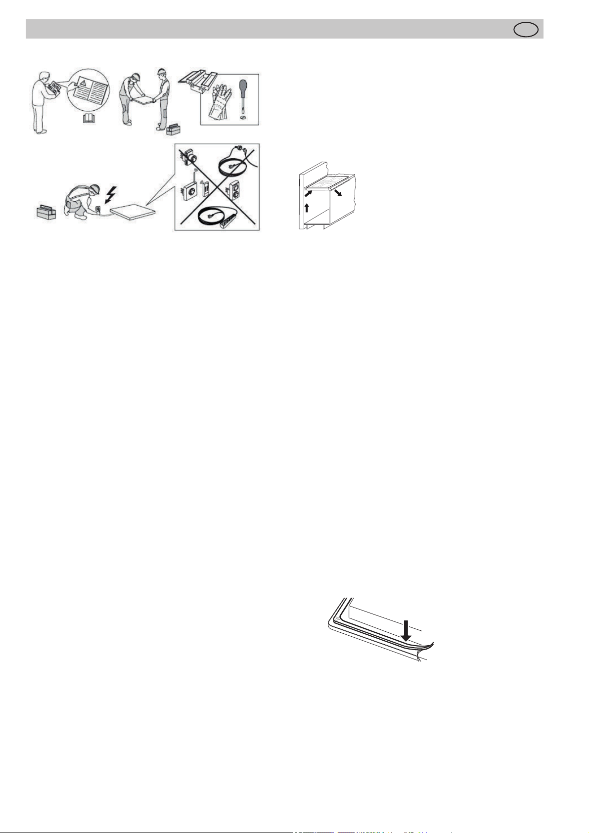
• Das Gerät muss immer von mindestens zwei Personen
bewegt und eingebaut werden - Unfallgefahr! Tragen
Sie beim Auspacken und Einbau Schutzhandschuhe
zur Vermeidung von Schnittverletzungen.
• Furniere, Kleber bzw. Kunststoff beläge der angrenzenden Möbel müssen temperaturbeständig sein (min.
75°C). Sind die Furniere und Beläge nicht genügend
temperaturbeständig, können sie sich verformen.
• Der Berührungsschutz muss durch den Einbau gewährleistet sein.
• Die Verwendung von Wandabschlussleisten aus
Massivholz auf der Arbeitsplatte hinter dem Kochfeld
ist zulässig, sofern die Mindestabstände gemäß den
Einbauskizzen eingehalten werden.
• Die Mindestabstände der Muldenausschnitte nach hinten gemäß der Einbauskizze sind einzuhalten.
• Bei Einbau direkt neben einem Hochschrank ist ein Sicherheitsabstand von mindestens 50 mm einzuhalten.
Die Seitenfl äche des Hochschrankes muss mit wärmefestem Material verkleidet werden. Aus arbeitstechnischen Gründen sollte der Abstand jedoch mindestens
300 mm betragen.
• Der Abstand zwischen Kochfeld und Dunstabzugshaube muss mindestens so groß sein, wie in der Montageanleitung der Dunstabzugshaube vorgegeben ist.
• Die Verpackungsmaterialien (Plastikfolien, Styropor,
Nägel, etc.) müssen aus der Reichweite von Kindern
gebracht werden, da diese Teile mögliche Gefahrenquellen darstellen. Kleinteile könnten verschluckt werden und von Folien geht Erstickungsgefahr aus.
• Schaltet sich häufi g die Leistung einer Kochzone
2.3 Einbau
Wichtige Hinweise
• Die Installation, einschließlich der Wasserversorgung
• Übermäßige Hitzeentwicklung von unten z.B. von ei-
• Wenn bei Einbauherden der Pyrolysebetrieb stattfi ndet,
• Wenn das Gerät nicht über einem Ofen installiert ist,
• Der Einbau des Kochfeldes über Kältegeräten, Ge-
• Es ist dafür zu sorgen, dass wegen Brandgefahr keine
• Die 170 mm lange Frontleiste muss eingebaut werden
Kochfelddichtung
Vor dem Einbau ist die beiliegende Kochfelddichtung
lückenlos einzulegen.
2.2 Belüftung
• Das Induktionskochfeld verfügt über einen Lüfter der
automatisch ein- und abschaltet. Wenn die Temperaturwerte der Elektronik eine gewisse Schwelle überschreiten startet der Lüfter mit kleiner Geschwindigkeit. Wird
das Induktionskochfeld intensiv benutzt schaltet der
Lüfter auf eine höhere Geschwindigkeit. Ist die Elektronik ausreichend abgekühlt reduziert der Lüfter seine
Geschwindigkeit und schaltet wieder automatisch ab.
• Der Abstand zwischen Induktionskochfeld und Küchenmöbel bzw. Einbaugeräten muss so gewählt werden,
dass eine ausreichende Be- und Entlüftung der Induktion gewährleistet ist.
• Es muss verhindert werden, dass Flüssigkeiten zwi-
• Bei Einbau des Kochfeldes in eine unebene Arbeitsplat-
selbsttätig herunter oder ab (siehe Kapitel Überhitzungsschutz) so ist vermutlich die Kühlung nicht
ausreichend. In diesem Fall ist es empfehlenswert die
Rückwand des Unterschranks im Bereich des Arbeitsplattenausschnitts zu öff nen sowie die vordere Traversleiste des Möbels über die gesamte Breite des Kochfeldes zu entfernen damit ein besserer Luftaustausch
gegeben ist.
Zur besseren Belüftung des Kochfeldes
wird vorne ein Luftspalt von mind. 5 mm
empfohlen.
(falls vorhanden) und der elektrischen Anschlüsse,
sowie die Reparaturen müssen von einem qualifi zierten
Techniker durchgeführt werden. Reparieren oder ersetzen Sie keine Teile des Gerätes, es sei denn, dies ist in
der Bedienungsanleitung ausdrücklich beschrieben.
nem Backofen ohne Querstromlüfter ist zu vermeiden.
darf das Induktionskochfeld nicht benutzt werden.
muss eine Trennwand (nicht im Lieferumfang enthalten) in dem Fach unter dem Gerät installiert werden,
das mindestens 20 mm breit ist.
schirrspülern sowie Wasch- und Trockengeräten ist
nicht zulässig.
feuergefährlichen, leicht entzündbaren oder durch Wärme verformbaren Gegenstände direkt neben oder unter
dem Kochfeld angeordnet bzw. gelegt werden.
und darf nur mit Werkzeug wieder entfernt werden.
schen Kochfeldrand und Arbeitsplatte oder zwischen
Arbeitsplatte und Wand in evtl. darunter eingebaute
Elektrogeräte eindringen können.
te, z.B. mit einem keramischen oder ähnlichem Belag
(Kacheln etc.) ist die evtl. an dem Kochfeld befi ndliche
Dichtung zu entfernen und die Abdichtung der Kochfl äche gegenüber der Arbeitsplatte durch plastische
Dichtungsmaterialien (Kitt) vorzunehmen.
6
Page 7
Montageanleitung
p
D
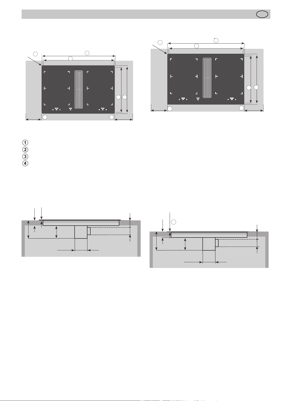
2.4 Variable Einbaumöglichkeit: aufl iegender
Einbau
Maße in mm
4
4
R5
min.50
Mindestabstand zu benachbarten Wänden
Ausschnittmaß
Ausfräßmaß
Kochfeldaussenmaß
1
2
800
750+1
1
500+1
2 4
min.50
520
2.5 Variable Einbaumöglichkeit: fl ächenbündiger
Einbau
R7
3
min.50
Dichtband in die Ecke der Aufl agekante der Arbeitsplatte
aufkleben, so dass sich kein Silikonkleber unter das Kochfeld durchdrücken kann.
Das Kochfeld ohne Kleber in den Arbeitsplattenausschnitt
einlegen und ausrichten. Gegebenenfalls Höhenausgleichsplatten unterlegen.
Den Spalt zwischen Kochfeld und Arbeitsplatte mit einem
hitzebeständigen Silikonkleber ausfugen.
1
2
804+1
750+1
3
500+1
524+1
3
2
min.50
1
166
46
Wichtig
Silikonkleber darf sich an keiner Stelle unter die Aufl agefl äche des Kochfeldes drücken. Ein späteres Herausnehmen
des Kochfeldes ist sonst nicht mehr möglich. Bei Nichtbeachtung keine Gewährleistung!
4
50
3
4,5 -0,5
120
84 x 455
64
90
120
84 x 455
60
90
170
7
Page 8
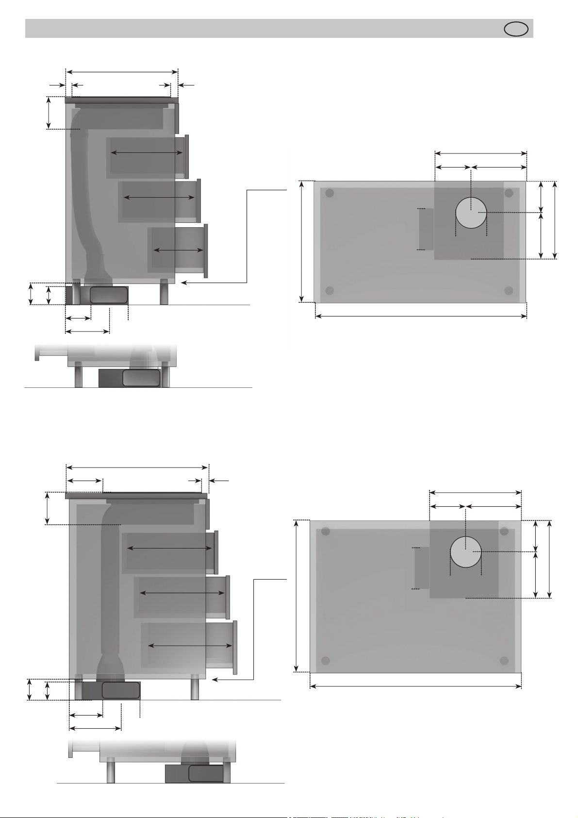
2.6 Abbildungen Küchenschrank
Arbeitsplatte 600 mm
40
170
40
Montageanleitung
D
100
min.
96
140
255
max.430
max.430
max.300
Abluftauslass links
Abluftauslass rechts
600
≥335
165
NW150
NW150
800
≥170
≥150220
Abluft wahlweise links oder rechts: Die Abluft kann
je nach Einbausituation links oder rechts gewählt
werden. Beachten Sie bitte hierzu die nebenstehenden Maße zur optimalen Planung.
≥370
100
min.
170
96
Arbeitsplatte
>120
140
255
> 600 mm
max. 430
max. 430
max. 430
Abluftauslass links
40
≥680
≥335
≥170165
≥150220
NW150
NW150
800
≥370
Abluft wahlweise links oder rechts: Die Abluft kann
je nach Einbausituation links oder rechts gewählt
werden. Beachten Sie bitte hierzu die nebenstehenden Maße zur optimalen Planung.
Abluftauslass rechts
8
Page 9
Montageanleitung
D
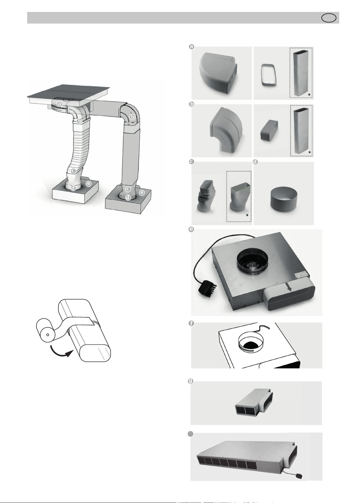
2.7 Zusammenbau Abluftsystem
Die Verbindung zwischen Kochfeld und Lüfter kann mit
einem Flexschlauch oder einem Flachkanal erfolgen.
Den Flachkanal nach Bedarf in der Länge mit einer Feinsäge kürzen.
Variante
Flexschlauch
Variante
Flachkanal
Abluftkanalkomponenten (* optionale Teile, nicht im Lieferumfang enthalten)
*
*
Zu Punkt c
Das fl exible Verbindungsstück wird bei einer Arbeitsplattentiefe von 600 mm verwendet. Achten Sie bei der Verlegung auf eine möglichst stramme und faltenfreie Installation Kürzen Sie hierzu überfl üssiges Material.
Zu Punkt f
Vor dem Aufstecken des Übergangstücks (d) auf den Sockellüfter (e) Dichtband am Anschlussstutzen Sockellüfter
(f) anbringen.
Wichtig:
Alle Komponenten müssen nach dem Zusammenstecken
mit dem beiliegendem Klebeband wie abgebildet dicht
verklebt werden.
Lüfter
Dichtband
Sockelfi lter (optional)
Aktivkohlefi lter
h
Plasmafi lter
9
Page 10

Montageanleitung
D
2.8 Wichtige Hinweise zum Einbau des Kochmul-
denlüfters
• Das Gerät muss immer von mindestens zwei Personen
bewegt und eingebaut werden - Unfallgefahr! Tragen
Sie beim Auspacken und Einbau Schutzhandschuhe
zur Vermeidung von Schnittverletzungen.
• Kinder immer aus dem Einbaubereich fernhalten.
• Überprüfen Sie das Gerät nach dem Auspacken auf
Transportbeschädigungen. Bei Problemen, wenden
Sie sich an den Händler oder ihren nächsten Kundendienst.
• Entfernen Sie nach dem Einbau alle Verpackungsabfälle (Plastik, Schaumstoff teile etc.) aus der Reichweite
von Kindern - Erstickungsgefahr.
• Das Gerät muss vor jeder Einbaumaßnahme vom
Stromnetz getrennt werden - Stromschlaggefahr. Stellen Sie beim Einbau sicher, dass das Netzkabel nicht
beschädigt wird - Feuergefahr und Stromschlaggefahr.
Benutzen Sie das Gerät nur, wenn es vollständig eingebaut ist.
• Alle Ausschnittarbeiten in Möbeln oder Arbeitsplatten
müssen vor dem Einbau durchgeführt werden. Entfernen Sie alle Holzabfälle und Sägespäne.
• Wenn das Gerät NICHT über einem Ofen eingebaut
wird, muss eine Trennwand (nicht im Lieferumfang
enthalten) in das Küchenmöbel unter dem Gerät eingebaut werden.
• Mauerkästen, sowie der Ausschnitt in der Sockelblende sollen im Querschnitt mindestens der Abluftleitung
entsprechen. Es muss eine Ausströmöff nung von
mindestens 500 cm² vorhanden sein. Die Sockelleisten
in der Höhe kürzen oder entsprechende Öff nungen
einbringen.
• Achten Sie bei der Installation darauf, dass die Umlufteinheit auch nach Fertigstellung der Küchenmontage
zugänglich bleibt. Gegebenenfalls müssen Sockelfüße
der Küchenschränke versetzt werden.
• Der Kochmulden-Lüfter kann in Abluft und Umluft betrieben werden.
• Die Abluft in einem für den Zweck vorgesehenen Lüftungsschacht oder durch die Hauswand nach draußen
führen.
• Die Abluft darf nicht in einen benutzten Rauch- oder
Abgaskamin geführt werden. Ziehen Sie im Zweifelsfall
den Bezirksschornsteinfegermeister hinzu.
• Wird im Umfeld des Kochmulden-Lüfters eine kaminabhängige Feuerstätte betrieben (Kohle-, Holz-, Öloder Gasfeuerung), dann muss für ausreichend Zuluft
gesorgt werden, ansonsten besteht Vergiftungsgefahr.
Ein gefahrloser Betrieb des Kochmulden-Lüfters ist
gewährleistet, wenn der durch den Kochmulden-Lüfter
ausgelöste Unterdruck 0,04 mbar (4 Pa) nicht überschreitet und ausreichend Zuluft in den Raum nachströmen kann.
• Abluftleitungen müssen der Brandklasse B 1 DIN 4102
entsprechen. Beachten Sie, dass die Mindestnennweite
des Anschlussstutzen des Gerätes nicht reduziert wird.
• Es sollte immer das zur Luftführung empfohlene und
mit dem Kochfeldabzug kompatible System eingesetzt
werden.
• Die Nennweite der Umluftrohre darf 150 mm nicht
unterschreiten.
• Abluftleitungen sollen so kurz wie möglich sein, nicht
im 90 Grad-Winkel sondern in weichen Bögen geführt
werden und keine Querschnittsreduzierungen haben.
• Rohrdurchmesser nie kleiner als 150 mm wählen. 50
cm vor dem Lüfterbaustein dürfen keine Bögen/Winkel
verlegt werden.
• Zwischen zwei Winkeln/Bögen immer ein gerades
Stück von ca. 50 cm einsetzen.
Montage
• Beachten Sie die allgemeinen gültigen Vorschriften der
Elektrizitätswerke sowie der Feuerpolizei.
• Montage/Anschluss durch Fachpersonal.
• Schäden durch Nichtbeachten dieser und dem Gerät
beigelegten Unterlagen können beim Hersteller nicht
geltend gemacht werden.
• Mindestabstände zu Wänden beachten: seitlich mindestens 100 mm und hinten mindestens 50 mm.
Tischausschnitt vorbereiten
• Ausschnitt einfräsen oder mit Holzleisten herstellen
• Ausschnitte massgenau und rechtwinklig
• Höhe sicherstellen, damit Kochfeld und Filtereinheit
genau passt
• Nischenentlüftung seitlich von min. 400 cm2 beachten
• Möbel und Abdeckungen müssen temperaturbeständig
sein (< 75°C).
• Filterset nur links einplanen.
Lüftereinheit einbauen
• Einheit (Aktivkohle oder Plasma) in die Nische stellen
• Luftstutzen ausrichten, fi xieren
• Elektrische Verbindungen herstellen
• Kochfeld einlegen, zentrieren
• Kochfeld während der Aushärtezeit des Silikons nicht in
Betrieb nehmen
• Vor dem Einkleben die Verwendbarkeit des Primers/
Einklebemasse testen
• Kochfeld nicht festschrauben, da es 18 kg wiegt (ohne
Filter)
• Brennbare Wände/Decken oberhalb der Kochfl ächen
müssen entsprechend dem zuständigen feuerpolizeilichen Organ feuerhemmend verkleidet sein.
Elektrisch anschliessen
• Sicherungen/Hauptschalter erst nach dem Einbau/Verkabelung des Kochfeldes einschalten.
• Beigelegtes Schild an gut sichtbarer Stelle befestigen,
da es nach dem Einbau nicht mehr zugänglich ist.
• Brennbare Wände/Decken oberhalb der Kochfl ächen
müssen entsprechend dem zuständigen feuerpolizeilichen Organ feuerhemmend verkleidet sein.
• Berührungsschutz des Kochfeldes durch ordnungsgemäßen Einbau sicherstellen.
• Der Aktivkohle- oder Plasma-Filter muss für Wartungszwecke so installiert werden, dass er stets leicht und
einfach zugänglich ist.
HINWEIS
Bei Umluftbetrieb ist für eine ausreichende
Be- und Entlüftung zu sorgen, um die Luftfeuchtigkeit abzuführen.
10
Page 11
Montageanleitung
D
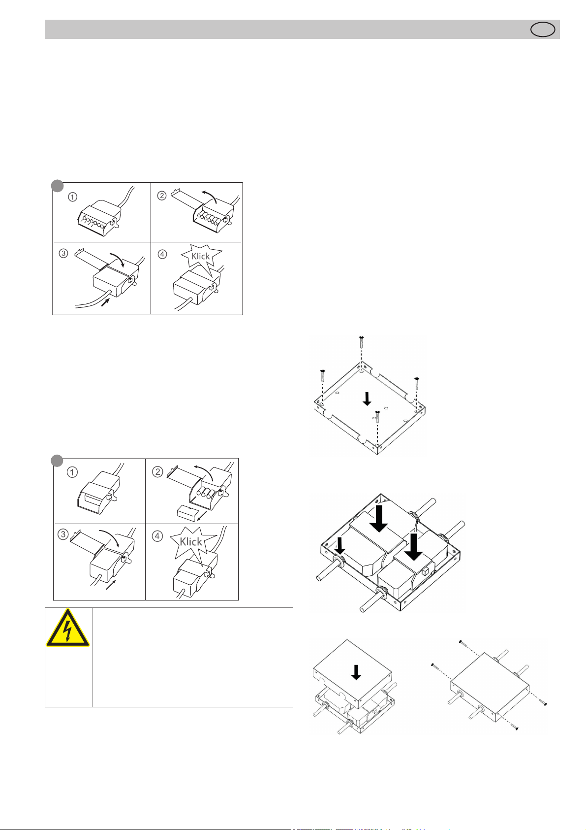
2.9 7-poliger Stecker Anschluss Lüfter
Vorgehensweise
Für den Lüfteranschluss verbinden Sie die beiden 7-poligen Stecker.
Steckersicherung am 7 poligen Stecker (Lüfter) des Kochfeldes öff nen und denn 7 poligen Gegenstecker vom Lüfter
aufstecken bis dieser sicher einrastet. Anschließend die
Steckersicherung wieder verschließen.
Die Stecker sind nach der Montage an der Rückwand oder
einer Schrankwand zu befestigen.
e
2.10 4-poliger Stecker Anschluss Plasmafi lter
(optional)
Vorgehensweise
Steckersicherung am 4 poligen Stecker (Plasma) des
Kochfeldes öff nen und Schutzabdeckung entfernen. Denn
4 poligen Gegenstecker vom Plasmafi lter (g) aufstecken
bis dieser sicher einrastet.
Anschließend die Steckersicherung wieder verschließen.
Die Stecker sind nach der Montage an der Rückwand oder
einer Schrankwand zu befestigen.
h
• Bei Anschluss des Gerätes ist eine Einrichtung vorzusehen, die es ermöglicht, das Gerät mit einer Kontakt-Öff nungsweite von mindestens 3 mm allpolig vom
Netz zu trennen. Als geeignete Trennvorrichtung gelten
LS-Schalter, Sicherungen und Schütze. Bei Anschluss
und Reparatur Gerät mit einer dieser Einrichtungen
stromlos machen.
• Der Schutzleiter muss so lang bemessen sein, dass er
bei Versagen der Zugentlastung erst nach den stromführenden Adern des Anschlusskabels auf Zug beansprucht wird.
• Die überschüssige Kabellänge muss aus dem Einbaubereich unterhalb des Gerätes herausgezogen werden.
• Bitte beachten Sie, dass die vorhandene Netzspannung mit der auf dem Typenschild übereinstimmt.
• Der vollständige Berührungsschutz muss durch den
Einbau sichergestellt sein.
• Achtung: Falschanschluss kann zur Zerstörung der
Leistungselektronik führen.
• Das Gerät ist nur für einen Festanschluss zugelassen.
Es darf nicht mit einem Schukostecker angeschlossen
werden.
Montage der Metallabdeckung für die Stecker
Befestigen Sie das untere Gehäuse an der Wand (Schrauben nicht im Lieferumfang enthalten).
WARNUNG VOR ELEKTRISCHER
ENERGIE!
ES BESTEHT LEBENSGEFAHR!
In der Nähe dieses Symbols sind spannungsführende Teile angebracht. Abdeckungen, die damit gekennzeichnet sind, dürfen
nur von einer anerkannten Elektrofachkraft
entfernt werden.
• Der elektrische Anschluss darf nur von einem autorisierten Fachmann vorgenommen werden!
• Die gesetzlichen Vorschriften und Anschlussbedingungen des örtlichen Elektroversorgungsunternehmens
müssen vollständig eingehalten werden.
Legen Sie die Stecker mit den Kabelschutztüllen ein.
Schließen Sie die Abdeckung mit den 4 Schrauben (mitgeliefert). Auch wenn einer der in den obigen Abbildungen
gezeigten Stecker nicht verwendet wird, achten Sie darauf,
dass er auch in die Metallabdeckung eingesetzt wird.
11
Page 12
Montageanleitung
D
2.11 Einbau Kochmulden Lüfter
• Das Produkt darf nur von einem zugelassenen Fachmann unter Beachtung der örtlich geltenden Vorschriften angeschlossen werden, gleiches gilt für die Abluftanschlüsse. Der Installateur ist für die einwandfreie
Funktion am Aufstellort verantwortlich!
• Beachten Sie beim Einbau die einschlägigen Bauverordnungsvorschriften der Länder und der Energieversorgungsunternehmen.
• Der Kochmulden-Lüfter kann in Abluft und Umluft betrieben werden.
• Die Abluft in einem für den Zweck vorgesehenen Lüftungsschacht oder durch die Hauswand nach draußen
führen.
• Die Abluft darf nicht in einen benutzten Rauch- oder
Abgaskamin geführt werden. Ziehen Sie im Zweifelsfall
den Bezirksschornsteinfegermeister hinzu.
• Wird im Umfeld des Kochmulden-Lüfters eine kaminabhängige Feuerstätte betrieben (Kohle-, Holz-, Öloder Gasfeuerung), dann muss für ausreichend Zuluft
gesorgt werden, ansonsten besteht Vergiftungsgefahr.
Ein gefahrloser Betrieb des Kochmulden-Lüfters ist
gewährleistet, wenn der durch den Kochmulden-Lüfter
ausgelöste Unterdruck 0,04 mbar (4 Pa) nicht überschreitet und ausreichend Zuluft in den Raum nachströmen kann.
• Abluftleitungen müssen der Brandklasse B 1 DIN 4102
entsprechen.
• Beachten Sie, dass die Mindestnennweite des Anschlussstutzen des Gerätes nicht reduziert wird.
• Es sollte immer das zur Luftführung empfohlene und
mit dem Kochfeldabzug kompatible System eingesetzt
werden.
• Die Nennweite der Umluftrohre darf 150 mm nicht
unterschreiten.
• Abluftleitungen sollen so kurz wie möglich sein, nicht
im 90 Grad-Winkel sondern in weichen Bögen geführt
werden und keine Querschnittsreduzierungen haben.
• Rohrdurchmesser nie kleiner als 150 mm wählen. 50
cm vor dem Lüfterbaustein dürfen keine Bögen/Winkel
verlegt werden.
• Zwischen zwei Winkeln/Bögen immer ein gerades
Stück von ca. 50 cm einsetzen.
• Mauerkästen, sowie der Ausschnitt in der Sockelblende sollen im Querschnitt mindestens der Abluftleitung
entsprechen. Es muss eine Ausströmöff nung von
mindestens 500 cm² vorhanden sein. Die Sockelleisten
in der Höhe kürzen oder entsprechende Öff nungen
einbringen.
• Achten Sie bei der Installation darauf, dass die Umlufteinheit auch nach Fertigstellung der Küchenmontage zugänglich bleibt.
• Gegebenenfalls müssen Sockelfüße der Küchenschränke versetzt werden.
Anschlusswerte
Netzspannung: 380-415V 3N~, 50/60Hz
Komponentennennspannung: 220-240V
Anschlussleitung werkseitig vorhanden
• Das Kochfeld ist werkseitig mit einer temperaturbeständigen Anschlussleitung ausgestattet.
• Der Netzanschluss wird gemäß dem Anschlussschema
vorgenommen, ausgenommen die Anschlussleitung ist
bereits mit einem Stecker ausgestattet.
• Wenn die Netzanschlussleitung dieses Gerätes beschädigt wird, muss sie durch eine besondere Anschlussleitung ersetzt werden. Um Gefährdungen zu
vermeiden, darf dieses nur durch den Hersteller oder
seinen Kundendienst erfolgen.
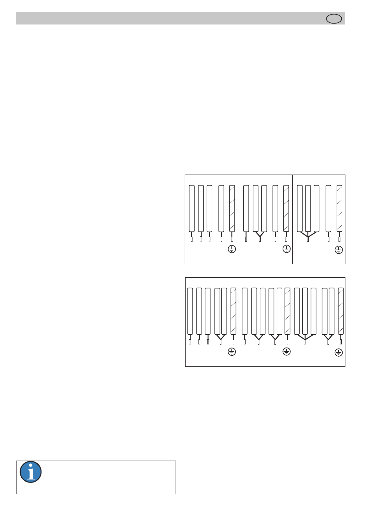
Anschlussmöglichkeiten
380-415 V 3N~
grau
braun
schwarz
L2
L1
L1
braun
schwarz
L2
L3
grau
L3
blau
N
blau
weiss
N
380-415 V 2N~
grün-gelb
schwarz
L1
380-415 V 2N~380-415 V 3N~
schwarz
grün-gelb
L1
braun
L2
grau
braun
L2
grau
blau
N
blau
weiss
N
220-240 V 1N~
schwarz
grün-gelb
L1
220-240 V 1N~
braun
schwarz
grün-gelb
L1
braun
grau
grau
blau
N
weiss
N
grün-gelb
blau
grün-gelb
12
HINWEIS
Bei Umluftbetrieb ist für eine ausreichende
Be- und Entlüftung zu sorgen, um die Luftfeuchtigkeit abzuführen.
Page 13
Montageanleitung
D
2.12 Technische Daten
Abmessungen Kochfeld
Höhe/ Breite/ Tiefe ....mm 170 x 800 x 520
Kochzonen
vorne links . . . . . Ø cm / kW
hinten links. . . . . Ø cm / kW
hinten rechts . . . Ø cm / kW
vorne rechts . . . . Ø cm / kW
Kochfeld ......................kW
Lüfter ...........................kW
Plasma ........................kW
* Leistung bei eingeschalteter Powerstufe
19 x 21 / 1,6 (1,85)*
19 x 21 / 2,1 (3,00)*
19 x 21 / 1,6 (1,85)*
19 x 21 / 2,1 (3,00)*
7,4
0,115
0,01
2.13 Inbetriebnahme
Nach dem Einbau des Feldes und nach dem Anlegen der
Versorgungsspannung (Netzanschluss) erfolgt zuerst ein
Selbst-Test der Steuerung und es wird eine Serviceinformation für den Kundendienst angezeigt.
Wichtig: Zum Netzanschluss dürfen keine Gegenstände
auf den Touch-Control Sensortasten sein!
Mit einem Schwamm und Spülwasser kurz über die Oberfl äche des Kochfeldes wischen und anschließend trockenreiben.
13
Page 14
3 Gerätebeschreibung
Gerätebeschreibung
D
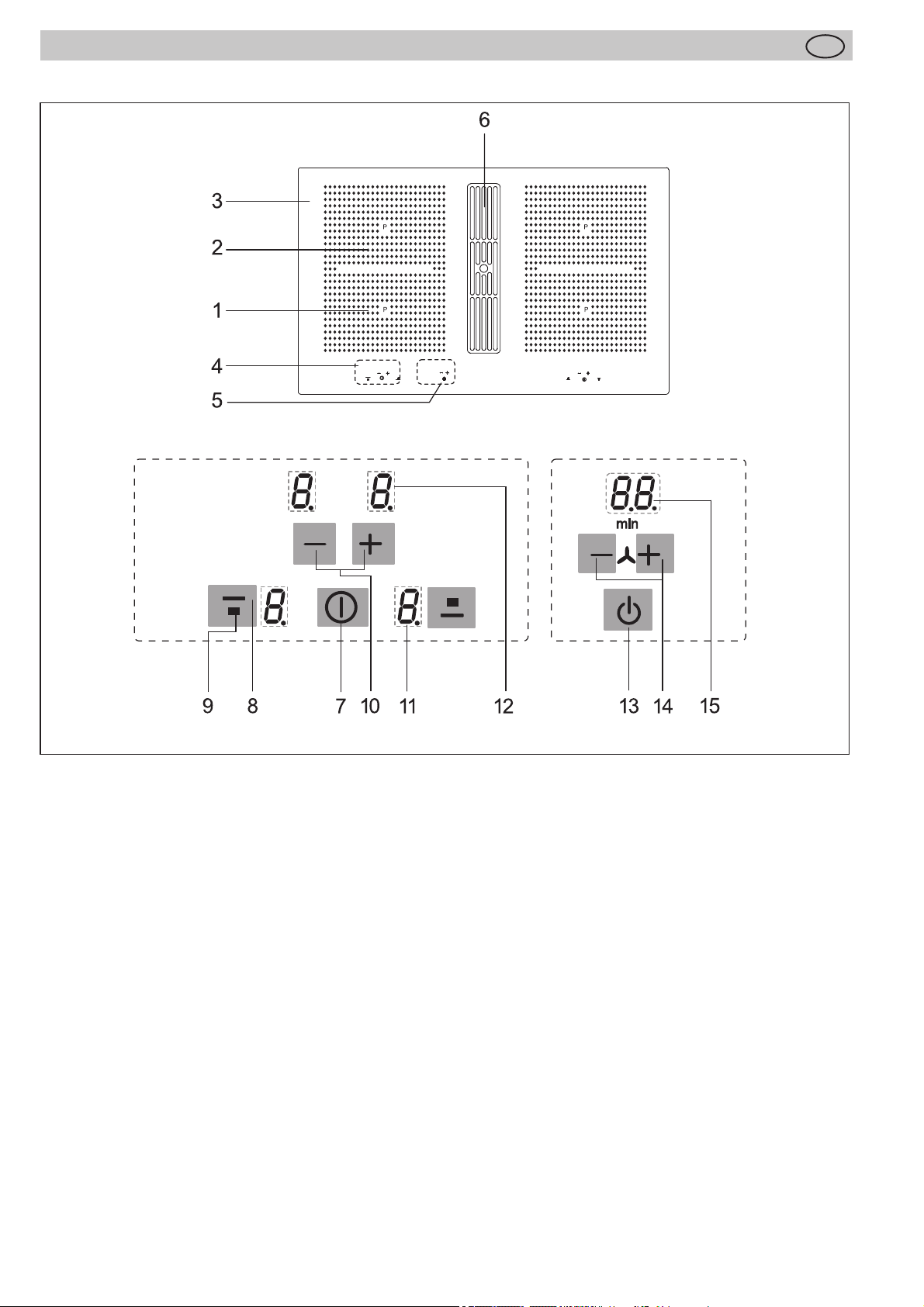
Das Dekor kann von den Abbildungen abweichen.
1. Induktionskochzone vorne links
2. Induktionskochzone hinten links
3. Glaskeramik-Kochfeld
4. Touch-Control Bedienfeld
5. Stand-by Taste und Lüftersteuerung
6. Lüfter
7. Ein/Aus-Taste (Kochfeld)
8. Kochzonenauswahl-Taste
9. Symbol zur Zuordnung der Lage der Kochzone auf
dem Glaskeramik-Kochfeld
10. Plus-Taste (erhöhen) / Minus-Taste (verringern)
11. Kochstufen-Anzeige
12. Timeranzeige
13. Stand-by Taste
14. Minus- /Plus-Taste Lüfter
15. Anzeige Lüfter
14
Page 15
Gerätebeschreibung
D
3.1 Bedienung durch Sensortasten
Die Bedienung des Glaskeramik-Kochfeldes erfolgt durch
Touch-Control Sensortasten. Die Sensortasten funktionieren wie folgt: mit der Fingerspitze ein Symbol auf der
Glaskeramikoberfl äche kurz berühren. Jede korrekte Betätigung wird durch einen Signalton bestätigt.
Nachfolgend wird die Touch-Control Sensortaste als „Taste” bezeichnet.
Stand-by Taste
Mit dieser Taste wird das Gerät betriebsbereit geschaltet.
Die Taste ist sozusagen der Hauptschalter. Nach dem
Ausschalten über diese Taste bleibt das Gerät noch ca.
120 Min. in Betriebsbereitschaft.
Achtung! Hat das Gerät komplett abgeschaltet, wird auch
keine Restwärmeanzeige mehr angezeigt!
Ein-/Aus-Taste (7) Kochzonen links oder rechts
Mit dieser Taste wird die linke oder rechte Kochfeldseite
ein- und ausgeschaltet.
Kochzonenauswahl-Taste; z.B. vorne (8)
Durch Betätigung einer der zur Verfügung stehenden
Kochzonenauswahl-Tasten wird eine Kochzone ausgewählt, für die anschließend mit der Plus-Taste oder
Minus-Taste eine Kochstufe eingestellt werden kann.
(13)
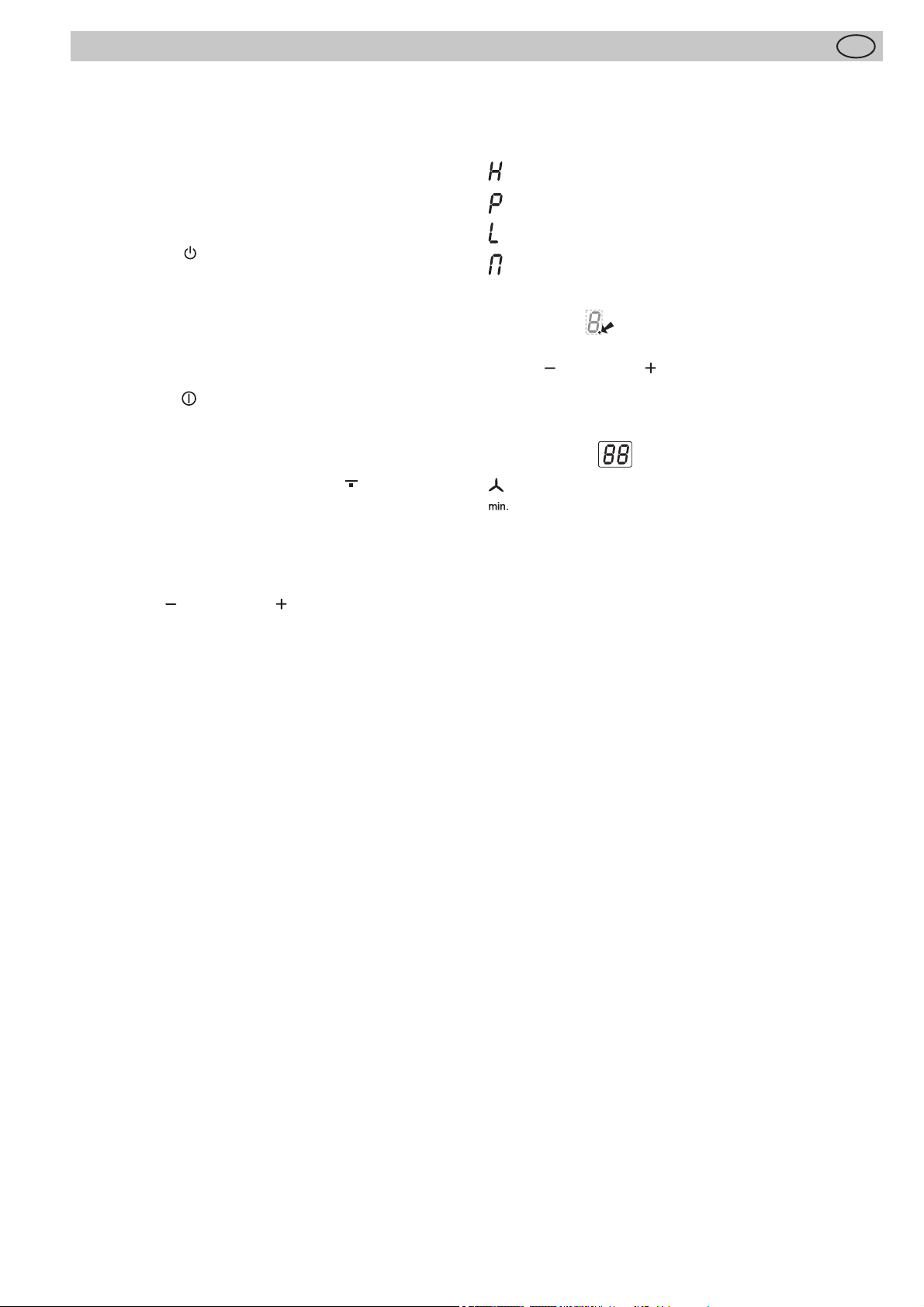
Kochstufen-Anzeige (11)
Die Kochstufen-Anzeige zeigt die gewählte Kochstufe,
oder:
leuchtet hell Kochzone ist ausgewählt (selektiert)
........................................... Restwärme
........................................... Powerstufe
............................................ Verriegelung
........................................... Brückenfunktion
ER03 .....................................Fehlermeldung
Kontrolllampe ................Timerfunktion
Minus- /Plus-Taste Lüfter (14)
Mit diesen Tasten wird der Lüfter (Dunstabzug) bedient. Er
kann unabhängig vom Kochfeld betrieben werden.
Anzeige Lüfter (16)
.................Lüfterstufe
................Lüfternachlauf
Minus-Taste / Plus-Taste (10)
Mit diesen Tasten werden die Einstellungen der Kochstufen, der Abschaltautomatik und des Kurzzeitweckers
vorgenommen.
Durch die Minus-Taste wird der Anzeigewert verringert,
durch die Plus-Taste erhöht.
15
Page 16
Bedienung
D
4 Bedienung
4.1 Das Induktionskochfeld
Die Kochfl äche ist mit einem Induktionskochfeld ausgestattet. Eine Induktionsspule unterhalb der Glaskeramik-Kochfl äche erzeugt ein elektromagnetisches Wechselfeld, das
die Glaskeramik durchdringt und im Geschirrboden den
wärmeerzeugenden Strom induziert.
Bei einer Induktionskochzone wird die Wärme nicht mehr
von einem Heizelement über das Kochgefäß auf die zu
garende Speise übertragen, sondern die erforderliche
Wärme wird mit Hilfe von Induktionsströmen direkt im
Kochgefäß erzeugt.
Vorteile des Induktionskochfeldes
• Energiesparendes Kochen durch direkte Energieübertragung auf den Topf (geeignetes Geschirr aus magnetisierbarem Material ist notwendig),
• erhöhte Sicherheit, da die Energie nur bei aufgesetztem Topf übertragen wird,
• Energieübertragung zwischen Induktionskochzone und
Topfboden mit hohem Wirkungsgrad,
• hohe Aufheizgeschwindigkeit,
• Verbrennungsgefahr ist gering, da die Kochfl äche nur
durch den Topfboden erwärmt wird, überlaufendes
Kochgut brennt nicht fest,
• schnelle, feinstufi ge Regelung der Energiezufuhr.
4.2 Topferkennung
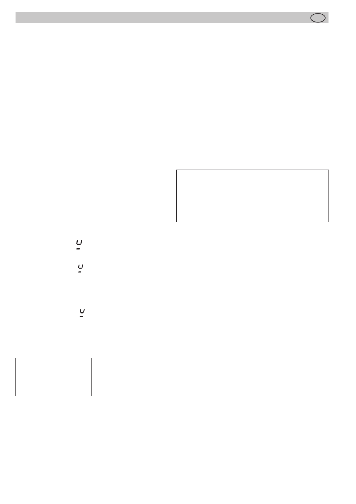
Steht bei eingeschalteter Kochzone kein oder ein zu kleiner Topf auf der Kochzone, so erfolgt keine Energieübertragung. Ein blinkendes in der Kochstufenanzeige weist
darauf hin.
Wird ein geeigneter Topf auf die Kochzone gestellt, schaltet sich die eingestellte Stufe ein und die Kochstufen-Anzeige leuchtet. Die Energiezufuhr wird unterbrochen,
wenn das Gefäß entfernt wird, in der Kochstufenanzeige
erscheint ein blinkendes .
Falls kleinere Töpfe oder Pfannen aufgesetzt werden, bei
denen die Topferkennung aber noch einschaltet, wird nur
soviel Leistung abgegeben, wie diese benötigen.
Topferkennungsgrenzen
Kochzonen-Durchmesser
(mm)
190 x 210 mm 120
Empfohlener Mindest-
durchmesser Topfboden
(mm)
4.3 Betriebsdauerbegrenzung
Das Induktionskochfeld besitzt eine automatische Betriebsdauerbegrenzung.
Die kontinuierliche Nutzungsdauer jeder Kochzone ist
abhängig von der gewählten Kochstufe (siehe Tabelle).
Voraussetzung ist, dass während der Nutzungsdauer keine Einstellungsänderung an der Kochzone vorgenommen
wird.
Wenn die Betriebsdauerbegrenzung angesprochen hat,
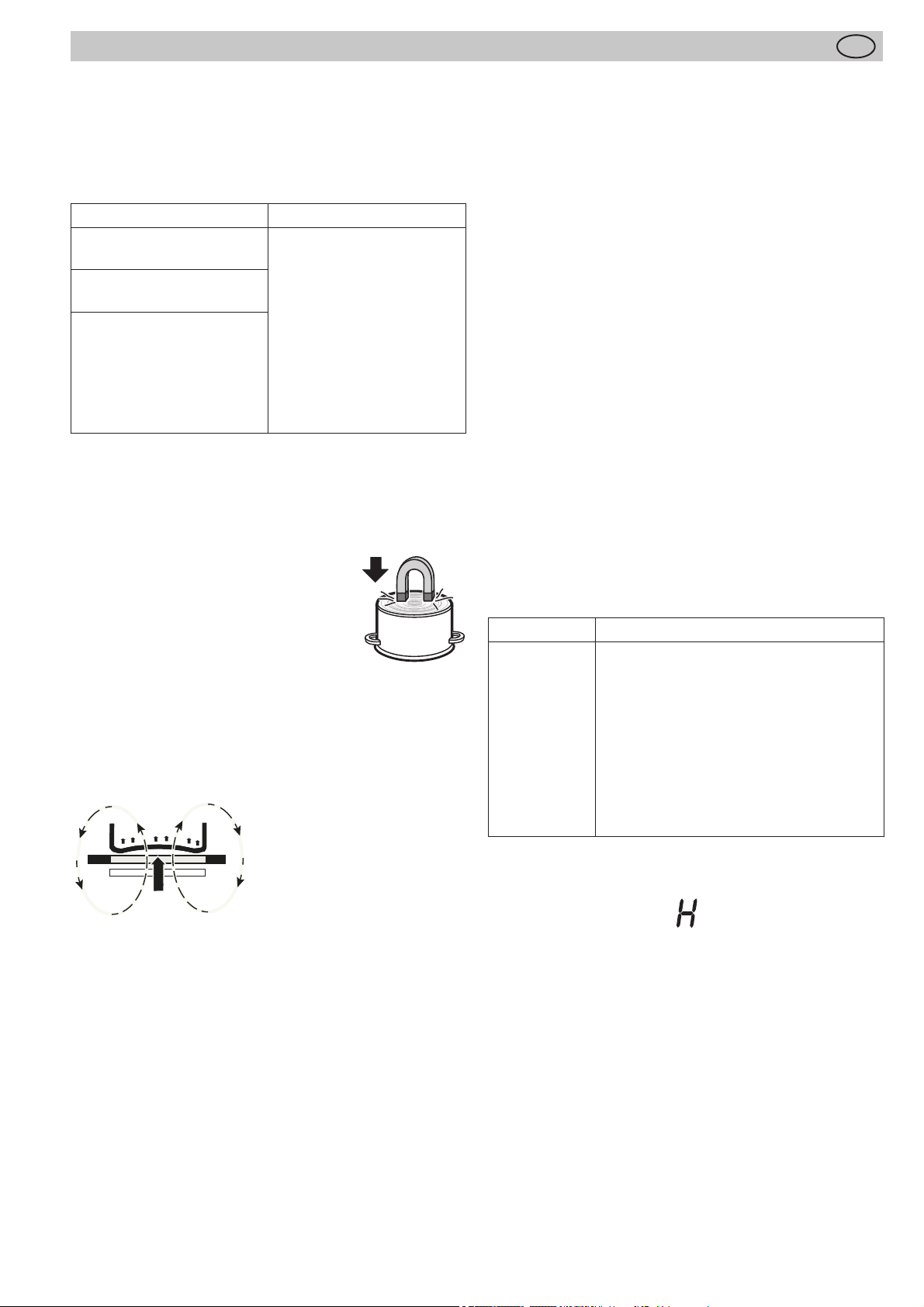
wird die Kochzone abgeschaltet, es ertönt ein kurzer Signalton und ein H erscheint in der Anzeige.
Die Abschaltautomatik hat gegenüber der Betriebsdauerbegrenzung Vorrang, d.h. die Kochzone wird erst abgeschaltet, wenn die Zeit der Abschaltautomatik abgelaufen
ist (z.B. Abschaltautomatik mit 99 Minuten und Kochstufe 9
ist möglich).
Betriebsdauerbegrenzung
Eingestellte
Kochstufe
1, 2
3, 4
5
6, 7, 8, 9
Betriebsdauerbegrenzung in
Stunden
6
5
4
1,5
4.4 Sonstige Funktionen
Bei längerem oder gleichzeitigem Betätigen von einer oder
mehreren Sensortasten (z.B. durch einen versehentlich
auf die Sensortasten gestellten Topf) erfolgt keine Schaltfunktion.
Es ertönt ein Signalton und ER03 wird angezeigt. Nach einigen Sekunden wird abgeschaltet. Bitte den Gegenstand
von den Sensortasten entfernen.
4.5 Überhitzungsschutz (Induktion)
Bei längerem Gebrauch der Kochfl äche mit voller Leistung
kann bei hoher Raumtemperatur die Elektronik nicht mehr
im erforderlichen Umfang gekühlt werden.
Damit keine zu hohen Temperaturen in der Elektronik
auftreten, wird ggf. die Leistung der Kochzone selbsttätig
herunter geregelt.
Sollten bei normalem Gebrauch der Kochfl äche und
normaler Raumtemperatur häufi g E2 oder ER21 angezeigt
werden, so ist vermutlich die Kühlung nicht ausreichend.
Fehlende Kühlöff nungen im Möbel können die Ursache
sein. Ggf. ist der Einbau zu überprüfen (siehe Kapitel
Belüftung).
Das Kochgeschirr darf einen bestimmten Bodendurchmesser nicht unterschreiten, da sich die Induktion sonst nicht
einschaltet. Den Topf immer in der Mitte der Kochzone
zentrieren, um den besten Wirkungsgrad zu erzielen.
Wichtig: Je nach Topfqualität kann der erforderliche Mindestdurchmesser zum Ansprechen der Topferkennung
abweichen!
16
Page 17
Bedienung
D
4.6 Geschirr für Induktionskochfeld
Das für die Induktionskochfl äche benutzte Kochgefäß
muss aus Metall sein, magnetische Eigenschaften haben
und eine ausreichende Bodenfl äche besitzen.
Benutzen Sie nur Töpfe mit induktionsgeeignetem Boden.
Geeignete Kochgefäße Ungeeignete Kochgefäße
Emaillierte Stahlgefäße mit
starkem Boden
Gusseiserne Gefäße mit
emaillierten Boden
Gefäße aus rostfreiem
Mehrschichten-Stahl,
rostfreiem Ferritstahl bzw.
Aluminium mit Spezialboden
So können Sie die Eignung des Gefäßes feststellen:
Führen Sie den nachfolgend beschriebenen Magnettest
durch oder vergewissern Sie sich, dass das Gefäß das
Zeichen für die Eignung zum Kochen mit Induktionsstrom
trägt.
Magnettest:
Führen Sie einen Magneten an den
Boden Ihres Kochgefäßes heran. Wird er
angezogen, so können Sie das Kochgefäß auf der Induktionskochfl äche benutzen.
Hinweis:
Beim Gebrauch induktionsgeeigneter Töpfe einiger Hersteller können Geräusche auftreten, die auf die Bauart
dieser Töpfe zurückzuführen sind.
Gefäße aus Kupfer, rostfreiem Stahl, Aluminium,
feuerfestem Glas, Holz,
Keramik bzw. Terrakotta
4.7 Energiespartipps
Nachfolgend fi nden Sie einige wichtige Hinweise, um energiesparend und effi zient mit Ihrem neuen Induktionskochfeld und dem Kochgeschirr umzugehen.
• Der Topfbodendurchmesser sollte gleich groß sein wie
der Kochzonendurchmesser.
• Beim Kauf von Töpfen darauf achten, dass häufi g der
obere Topfdurchmesser angegeben wird. Dieser ist
meistens größer als der Topfboden.
• Schnellkochtöpfe sind durch den geschlossenen Garraum und den Überdruck besonders zeit- und energiesparend. Durch kurze Gardauer werden Vitamine
geschont.
• Immer auf eine ausreichende Menge Flüssigkeit im
Schnellkochtopf achten, da bei leergekochtem Topf die
Kochzone und der Topf durch Überhitzung beschädigt
werden können.
• Kochtöpfe nach Möglichkeit immer mit einem passenden Deckel verschließen.
• Zu jeder Speisemenge sollte der richtige Topf verwendet werden. Ein großer kaum gefüllter Topf benötigt viel
Energie.
4.8 Kochstufen
Die Heizleistung der Kochzonen kann in mehreren Stufen
eingestellt werden. In der Tabelle fi nden Sie Anwendungsbeispiele für die einzelnen Stufen.
Kochstufe Geeignet für
0
1-2
3
4-5
6
7-8
9
P
Bei Kochtöpfen ohne Deckel muss evtl. eine höhere Kochstufe gewählt werden.
Aus-Stellung, Nachwärmenutzung
Fortkochen kleiner Mengen
Fortkochen
Fortkochen großer Mengen, Weiterbra-
ten größerer Stücke
Braten, Einbrenne herstellen
Braten
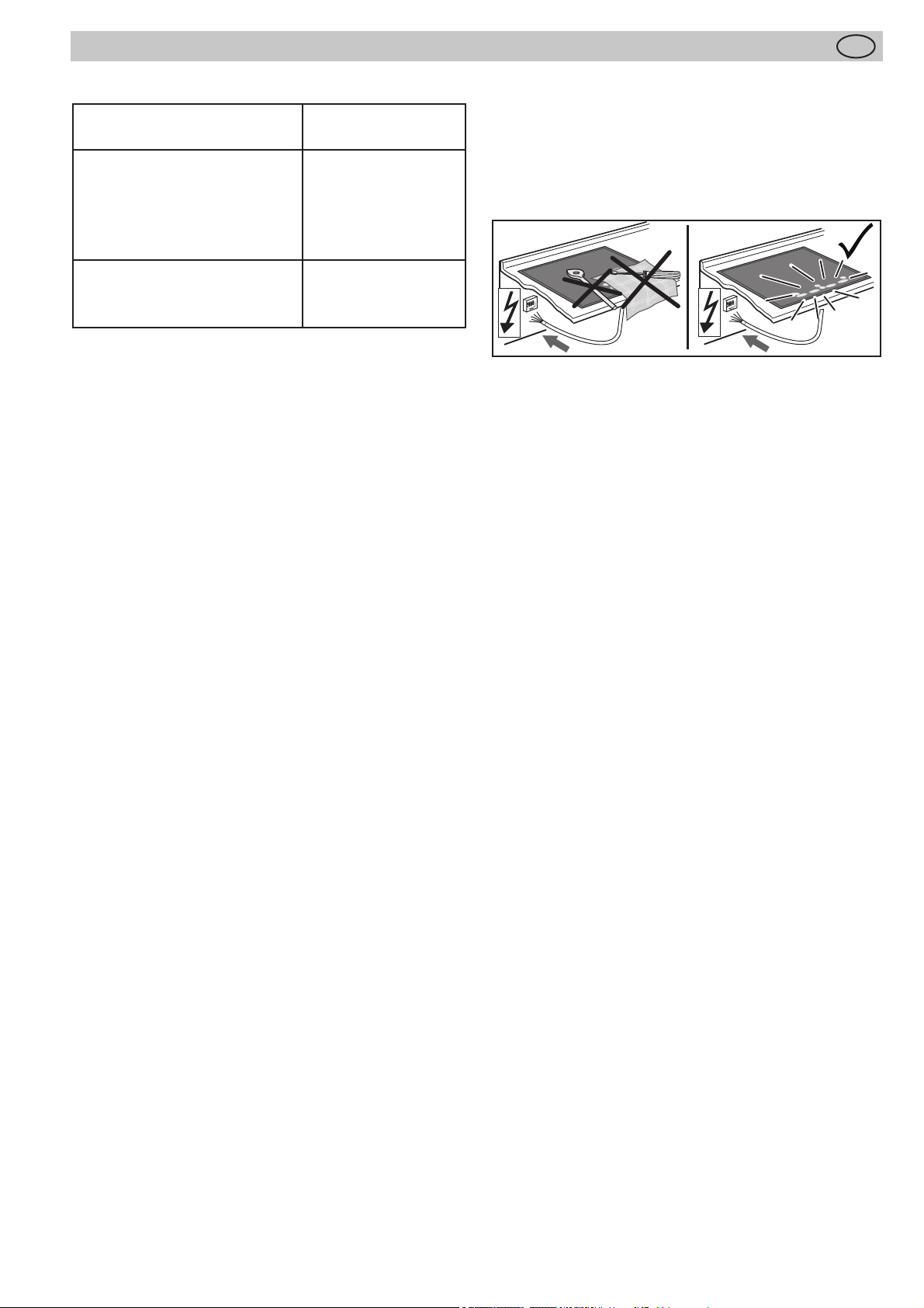
Ankochen, Anbraten, Braten
Powerstufe (höchste Leistung)
Falsch: der Geschirrboden ist gewölbt. Die Temperatur
kann von der Elektronik nicht korrekt ermittelt werden.
4.9 Restwärmeanzeige
Das Glaskeramik-Kochfeld ist mit einer Restwärmeanzeige
H ausgestattet.
Solange das H nach dem Ausschalten leuchtet, kann die
Restwärme zum Schmelzen und Warmhalten von Speisen
genutzt werden.
Nach dem Erlöschen des Buchstabens H kann die Kochzone noch heiß sein. Es besteht Verbrennungsgefahr!
Bei einer Induktionskochzone erhitzt sich die Glaskeramik
nicht direkt, sondern wird lediglich durch die Rückwärme
des Gefäßes erwärmt.
17
Page 18
induktionstauglich
Kochzonenauswahl-Taste
Bedienung
4.10 Gerät betriebsbereit schalten
Mit der Stand-by Taste wird das Gerät betriebsbereit
geschaltet. Die Taste ist sozusagen der Hauptschalter. Es
erfolgt zuerst ein Selbst-Test der Steuerung und die Anzeigen
leuchten kurz auf.
Nach dem Ausschalten über diese Taste bleibt das Gerät
noch ca. 120 Min. in Betriebsbereitschaft.
Achtung! Hat das Gerät komplett abgeschaltet, wird auch
keine Restwärmeanzeige mehr angezeigt!
4.11 Tastenbetätigung
Die hier beschriebene Steuerung erwartet nach der Betätigung einer (Auswahl-) Taste anschließend die Betätigung
einer nachfolgenden Taste.
Die Betätigung der nachfolgenden Taste muss grundsätzlich
innerhalb von 10 Sekunden begonnen werden, ansonsten
erlischt die Auswahl.
Die Plus-/ Minus-Tasten können einzeln angetippt werden
oder permanent gedrückt gehalten werden.
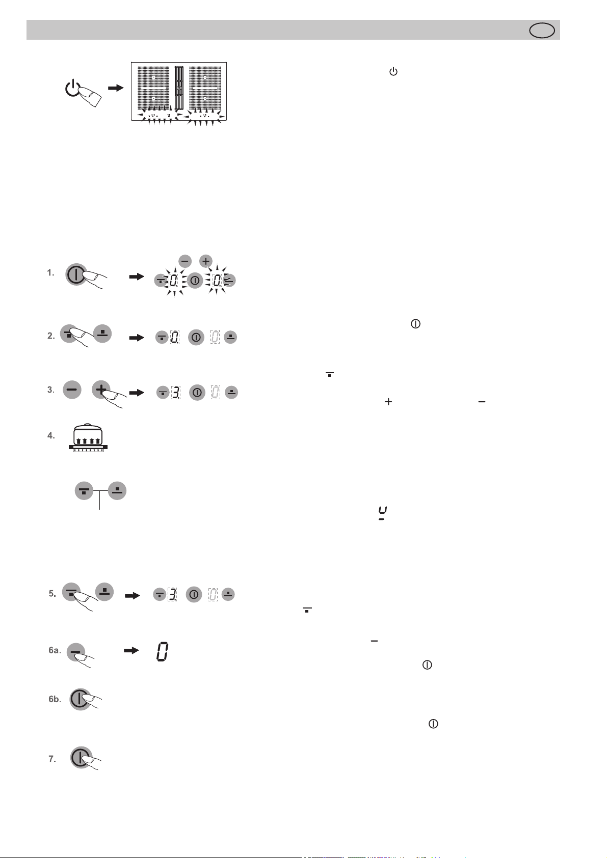
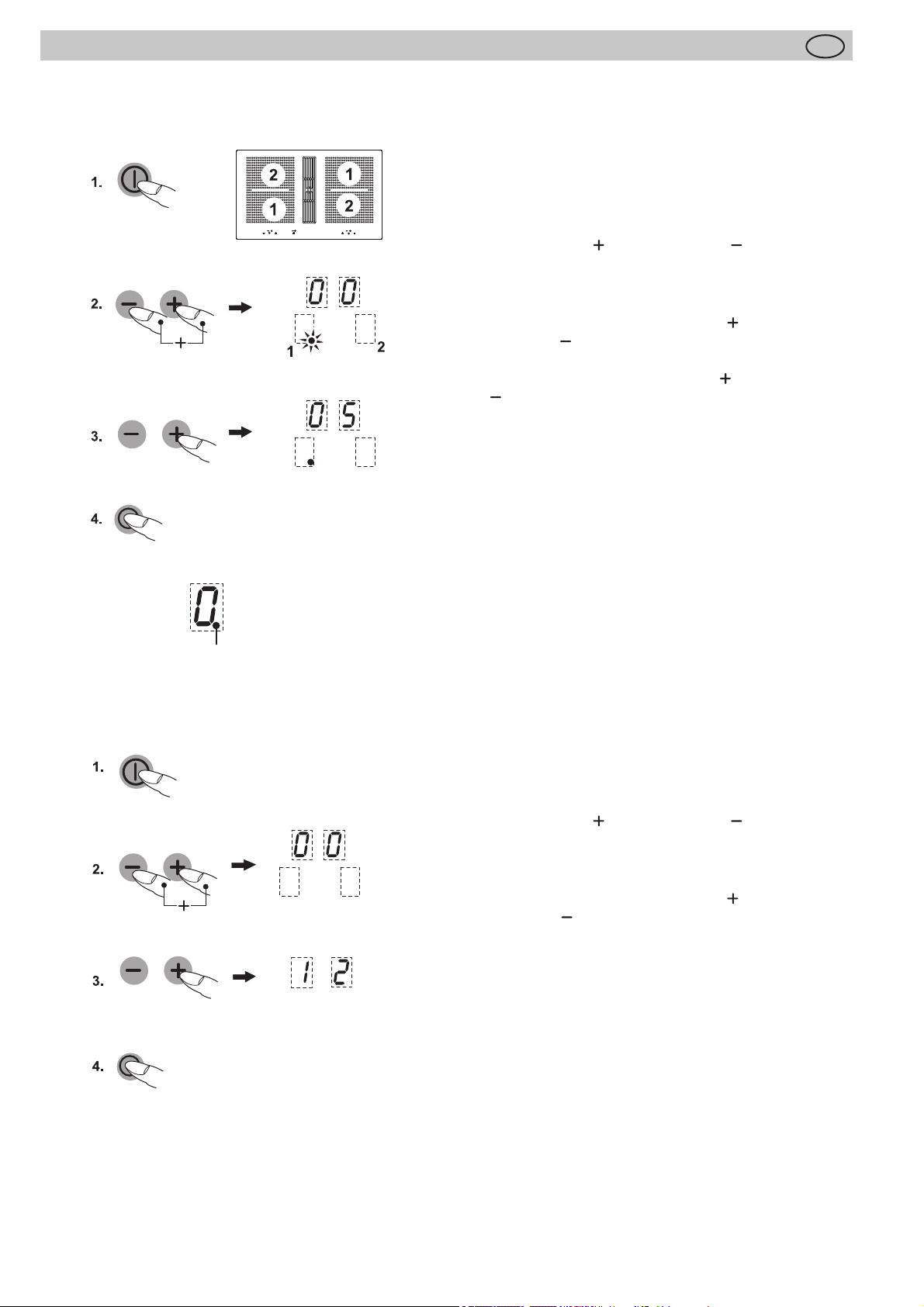
4.12 Kochfeld und Kochzone einschalten
1. Ein-/Aus-Taste Kochfeld solange betätigen (ca. 1 Sek.),
bis die Kochstufen-Anzeigen 0 zeigen. Die Steuerung ist
betriebsbereit.
2. Anschließend eine Kochzonenauswahl-Taste betätigen
(z.B. für vorne). Die ausgewählte Kochstufenanzeige
leuchtet hell.
3. Mit der Plus-Taste oder Minus-Taste eine Kochstufe auswählen. Durch die Plus-Taste wird die Kochstufe 1
eingeschaltet, durch die Minus-Taste die Kochstufe 9.
Gleich anschließend geeignetes induktionstaugliches
Kochgeschirr auf die Kochzone setzen. Die Topferkennung
schaltet die Induktionsspule ein. Das Gefäß wird aufgeheizt.
So lange kein Kochtopf auf die Kochzone gestellt wird,
wechselt die Anzeige zwischen der eingestellten Kochstufe
und dem Symbol . Ohne Topf wird aus Sicherheitsgründen die Kochzone nach 10 Minuten abgeschaltet. Hierzu
Kapitel „Topferkennung“ beachten.
Um zeitgleich auf anderen Kochzonen zu kochen, die
Punkte 2 bis 4 wiederholt durchführen.
D
18
4.13 Kochzone ausschalten
4. Die gewünschte Kochzonenauswahl-Taste betätigen (z.B.
für vorne). Die ausgewählte Kochstufenanzeige leuch-
tet hell.
5. a) Minus-Taste mehrmals betätigen, bis die Kochstufenanzeige 0 anzeigt, oder
b) Ein-/Aus-Taste Kochfeld betätigen. Das gesamte
Kochfeld wird abgeschaltet (alle Kochzonen werden abgeschaltet).
4.14 Kochfeld abschalten
6. Die Ein-/Aus-Taste Kochfeld betätigen. Das Kochfeld
wird unabhängig von der Einstellung ausgeschaltet.
Page 19
Bedienung
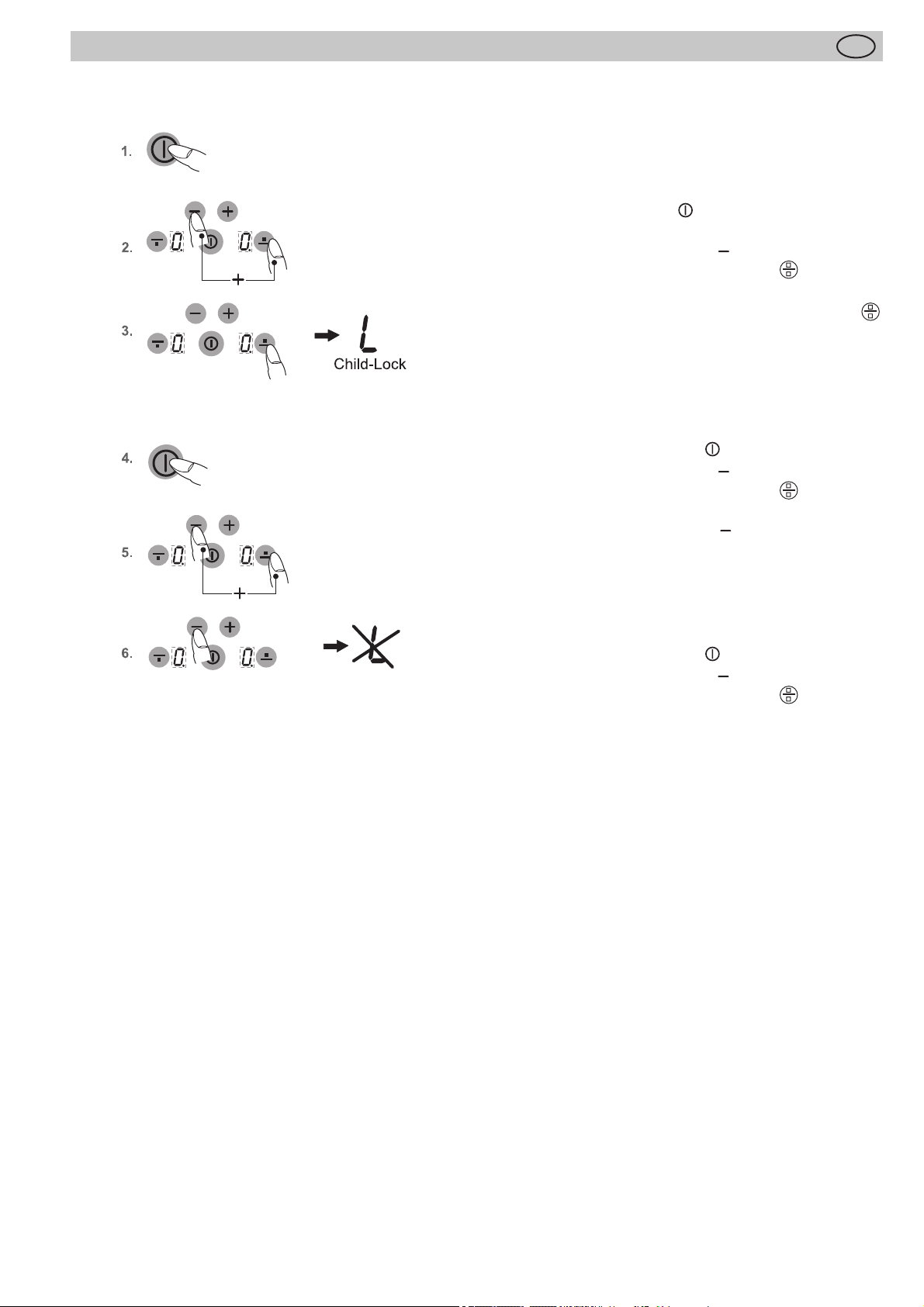
4.15 Verriegelung
Die Verriegelung soll verhindern, dass Kinder versehentlich oder absichtlich das Kochfeld einschalten. Dazu wird
die Bedienung gesperrt.
Verriegelung einschalten
1. Ein-/Aus-Taste Kochfeld
Kochfeld einzuschalten.
2. Gleich darauf die Minus-Taste und die rechts daneben liegende Kochzonenauswahl-Taste gleichzeitig
betätigen.
3. Anschließend die gleiche Kochzonenauswahl-Taste
betätigen, um die Verriegelung zu aktivieren.
In den Kochstufen-Anzeigen erscheint ein L für ChildLock; die Bedienung ist gesperrt und das Kochfeld
schaltet ab.
Verriegelung ausschalten
4. Die Ein-/Aus-Taste Kochfeld betätigen.
5. Gleich darauf die Minus-Taste und die rechts daneben liegende Kochzonenauswahl-Taste gleichzeitig
betätigen.
6. Anschließend die Minus-Taste betätigen, um die
Verriegelung auszuschalten. Das L erlischt.
D
betätigen um das gesamte
Verriegelung nur für einen Kochvorgang aufheben
Voraussetzung: Die Verriegelung ist nach Punkt 1-3 eingeschaltet.
• Die Ein-/Aus-Taste Kochfeld betätigen.
• Gleich darauf die Minus-Taste und die rechts daneben liegende Kochzonenauswahl-Taste gleichzeitig
betätigen.
Nachdem das L erloschen ist kann vom Benutzer eine
Kochzone eingeschaltet werden.
Nach dem Ausschalten des Kochfeldes ist die Verriegelung wieder aktiv (eingeschaltet).
Hinweis
Bei Netzausfall wird die eingeschaltete Verriegelung nicht
aufgehoben, d.h. sie bleibt erhalten (aktiviert).
19
Page 20
5 Minuten eingestellt
Bedienung
4.16 Abschaltautomatik (Timer)
Durch die Abschaltautomatik wird jede eingeschaltete
Kochzone nach einer einstellbaren Zeit automatisch abgeschaltet. Es können Kochzeiten von 01 bis 99 Minuten
eingestellt werden.
1. Das Kochfeld einschalten. Eine oder mehrere Koch-
2. Die Plus-Taste
3. Gleich darauf durch die Plus-Taste oder Mi-
4. Nach Ablauf der Zeit wird die Kochzone ausgeschal-
D
zonen einschalten und gewünschte Kochstufen
wählen.
und Minus-Taste gleichzeitig so
oft betätigen, bis die Kontrollleuchte (Dezimalpunkt)
der gewünschten Kochzone leuchtet. Die Timeranzeige leuchtet hell.
nus-Taste die Kochzeit eingeben.
Zur Programmierung der Abschaltautomatik für eine
weitere Kochzone, die Plus-Taste und Minus-Taste
gleichzeitig so oft betätigen, bis die Kontrollleuchte
(Dezimalpunkt) der jeweiligen Kochstufenanzeige
leuchtet.
tet. Es ertönt ein zeitlich begrenzter Signalton, der
durch Betätigung einer beliebigen Taste (ausgenommen Ein-/Aus-Taste) abgeschaltet werden kann.
Kontrollleuchte (Dezimalpunkt)
12 Minuten eingestellt
Hinweise
• Zur Kontrolle der abgelaufenen Zeit (Abschaltautomatik) die Plus-Taste und Minus-Taste gleichzeitig so oft
betätigen, bis die Kontrollleuchte (Dezimalpunkt) der
jeweiligen Kochstufenanzeige leuchtet. Der Anzeigewert kann abgelesen und verändert werden.
• Abschaltautomatik vorzeitig löschen: Die jeweilige
Kochzone anwählen und durch die Minus-Taste 0
einstellen.
4.17 Kurzzeitwecker (Eier-Uhr)
(Kochzone ausgeschaltet)
1. Das Kochfeld einschalten.
2. Die Plus-Taste und Minus-Taste gleichzeitig
einmal betätigen. Die Timeranzeige leuchtet hell. In
den Kochstufenanzeigen darf die Kontrollleuchte (Dezimalpunkt) nicht aufl euchten.
3. Gleich darauf durch die Plus-Taste oder Minus-Taste die Zeit in Minuten einstellen.
4. Nach Ablauf der Zeit ertönt ein zeitlich begrenzter
Signalton, der durch Betätigung einer beliebigen Taste
(ausgenommen Aus-Taste) abgeschaltet werden
kann.
20
Hinweis
• Der Kurzzeitwecker bleibt auch dann in Betrieb, wenn
die linke oder rechte Kochfeldseite ausgeschaltet ist.
Zum Ändern der Zeit die linke oder rechte Kochfeldseite einschalten.
Page 21
Bedienung
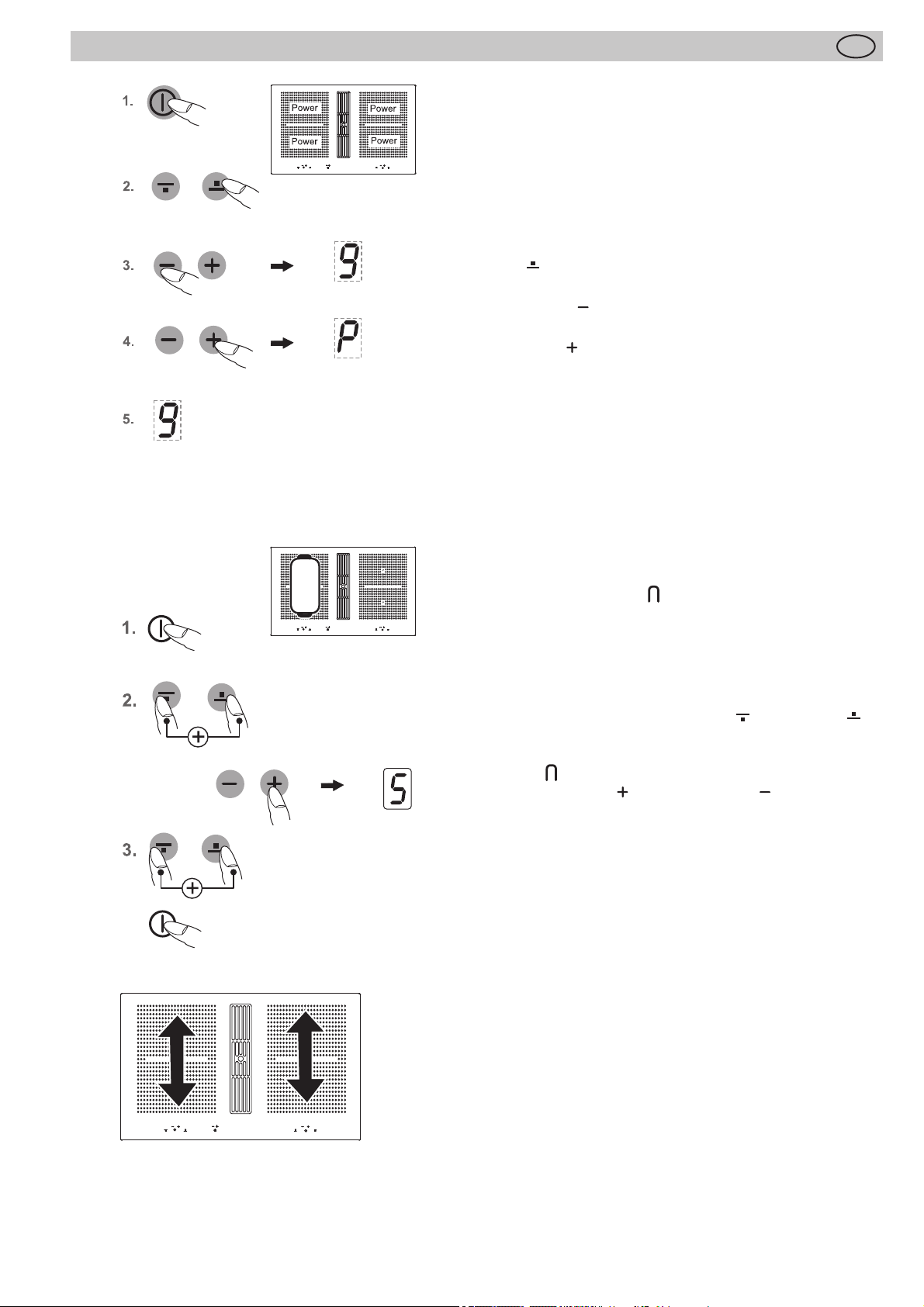
4.18 Powerstufe
Die Powerstufe stellt den Induktionskochzonen zusätzliche
Leistung zur Verfügung. Eine große Menge Wasser kann
schnell zum Kochen gebracht werden. Die Powerstufe arbeitet für 5 Minuten, anschließend wird automatisch auf Kochstufe 9 zurückgeschaltet.
1. Das Kochfeld einschalten.
2. Anschließend eine Kochzonenauswahl-Taste betätigen
(z.B.
leuchtet hell.
3. Minus-Taste einmal betätigen, um die höchste Kochstufe 9 einzustellen.
4. Plus-Taste einmal betätigen, um die Powerstufe zu
aktivieren. Die Kochstufenanzeige zeigt ein P.
5. Nach 5 Minuten wird die Powerstufe automatisch abgeschaltet. Das P erlischt und es wird auf Kochstufe 9
zurückgeschaltet.
Hinweise
• Zum vorzeitigen Abschalten der Powerstufe die Minus-Taste betätigen.
• Achtung, Überhitzungsgefahr! Kein Öl/ Frittierfett mit
der Powerstufe erhitzen.
für hinten). Die ausgewählte Kochstufenanzeige
D
Module (Powermanagement)
4.19 Brückenfunktion
Die vordere und die hintere Kochzone können für einen Kochvorgang zusammen geschaltet werden (Brückenfunktion).
Dadurch kann großes Geschirr verwendet werden.
1. Das Kochfeld einschalten.
2. Zum Einschalten der Brückenfunktion die beiden Kochzonenauswahl- Tasten der vorderen und hinteren
Kochzone gleichzeitig berühren.
Die Brückenfunktion ist eingeschaltet, es erscheint das
Symbol .
Mit der Plus-Taste oder Minus-Taste eine Kochstufe
auswählen.
3. Zum Deaktivieren die beiden Kochzonenauswahltasten erneut gleichzeitig betätigen oder das Kochfeld ausschalten.
Hinweise
Damit der Bräter bzw. Topf von der Topferkennung erkannt
wird, muss er die verwendeten Kochzonen mindestens bis zur
Hälfte abdecken!
4.20 Powermanagement
Je zwei Kochzonen sind -technisch bedingt- zu einem Modul
zusammengefasst und verfügen über eine maximale Leistung.
Wird dieser Leistungsbereich beim Einschalten einer hohen
Kochstufe oder der Powerfunktion überschritten, reduziert
das Powermanagement die Kochstufe der zugehörigen Modul-Kochzone.
Die Anzeige dieser Kochzone blinkt zunächst, danach wird die
maximal mögliche Kochstufe konstant angezeigt.
21
Page 22
Bedienung
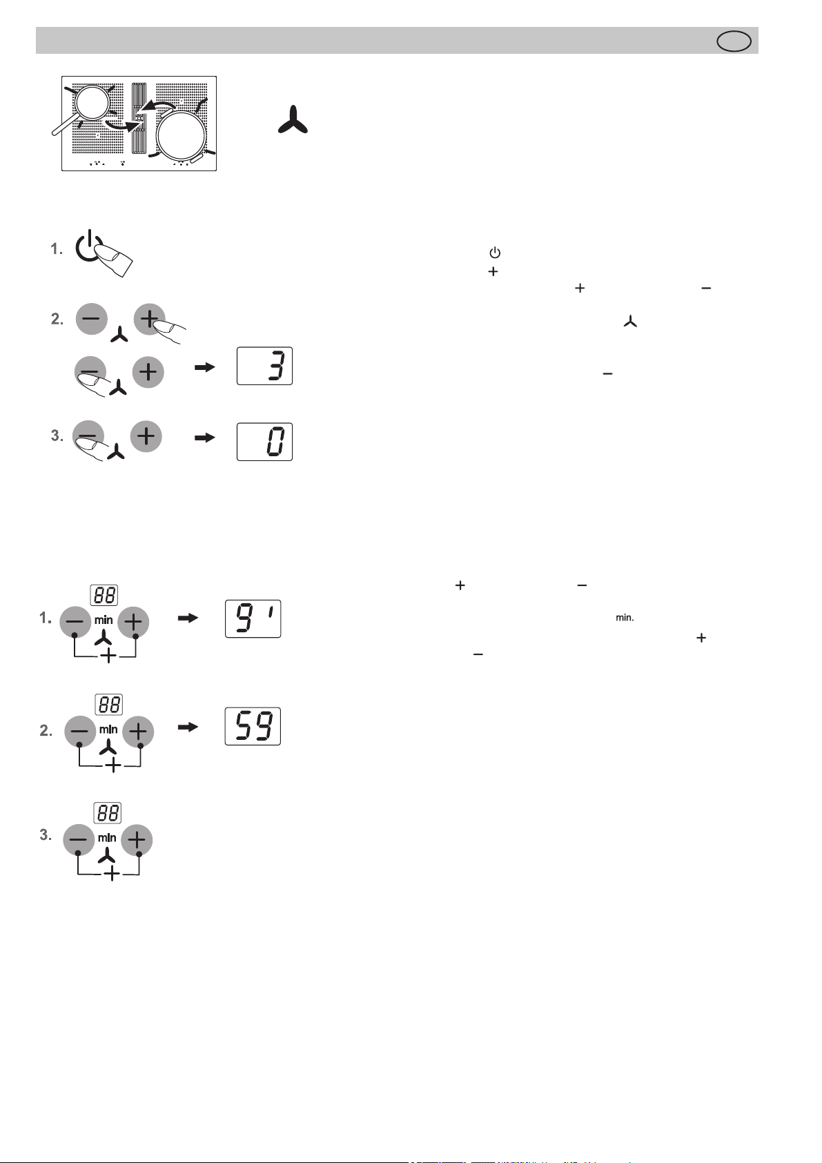
4.21 Lüfter verwenden
In der Mitte des Kochfeldes befi ndet sich der Lüfter mit dem
Abzug nach unten.
Wichtig:
Abdeckung nicht auf dem Induktionskochfeld ablegen!
Verbrennungsgefahr!
4.21.1 Lüfter ein- und ausschalten
1. Stand-by Taste
2. Die Plus-Taste vom Lüfter betätigen.
Danach kann durch die Plus- oder Minus-Taste eine
gewünschte Leistungsstufe 1, 2, 3 oder 4 gewählt werden.
Es leuchtet das Symbol für den Lüfter .
Die Intensivstufe 4 bleibt für 10 Minuten eingeschaltet, danach wird automatisch auf Stufe 3 zurückgeschaltet.
3. Zum Ausschalten die Minus-Taste vom Lüfter betätigen
bis 0 angezeigt wird.
Tipp
Damit der Abzug auch bei hohen Kochtöpfen (z. B. Spargeltopf)
gut funktioniert, können Sie auf der Lüfterseite einen Kochlöff el
unter den Kochtopfdeckel legen.
betätigen (ca. 1 Sek.)
D
4.21.2 Lüfternachlauf
Der Lüfternachlauf wird nach dem Kochen verwendet, um
Kochgerüche zu beseitigen. Außerdem werden die Filter im
Lüfter getrocknet.
Lüfternachlauf einstellen
1. Die Plus- und Minus-Taste vom Lüfter gleichzeitig
betätigen. Der Lüfternachlauf von 10 Minuten ist eingestellt.
Es leuchtet das Symbol für Nachlauf .
2. Durch erneutes gleichzeitiges Betätigen der Plus- und
Minus-Taste werden 60 Minuten eingestellt.
3. Durch erneutes gleichzeitiges Betätigen wird der Nachlauf
ausgeschaltet.
Die Lüfterstufe bei eingestelltem Lüfternachlauf ist frei einstellbar und veränderbar.
4.21.3 Nachlaufzeit
Nach jedem Kochvorgang sollte ein Nachlauf des Lüftermotors
von 10 – 20 Minuten erfolgen. Ist der Lüfter mindestens 15
Minuten in Betrieb, erfolgt nach dem Ausschalten ein automatischer Nachlauf von ca. 15 Minuten auf geringer Stufe.
So werden eine optimale Funktion und die Beseitigung von
restlichen Kochdünsten gewährleistet.
Bei Betrieb mit Umluftfi lter nutzen Sie nach dem Kochen bitte
stets eine Nachlaufzeit von 10 - 60 Minuten, um eine optimale
Geruchsbeseitigung zu erreichen.
Beim Wiedereinschalten des Lüfters kann es in seltenen Fällen
vorkommen, dass die im Filter gespeicherten Geruchsmoleküle
sich mit Wasserdampf verbinden und wieder wahrgenommen
werden können. Diese Restgerüche verschwinden im weiteren
Betrieb wieder.
Wichtig
Bei Umluftbetrieb ist für eine ausreichende Be- und Entlüftung
zu sorgen, um die Luftfeuchtigkeit abzuführen.
22
Page 23
Reinigung und Pfl ege
D
5 Reinigung und Pfl ege
• Vor dem Reinigen das Kochfeld ausschalten und abkühlen lassen.
• Das Glaskeramikkochfeld darf unter keinen Umständen mit einem Dampfreinigungsgerät oder ähnlichem
gereinigt werden!
• Beim Reinigen darauf achten, dass nur kurz über die
Ein-/ Aus-Taste gewischt wird. Damit wird ein versehentliches Einschalten vermieden!
5.1 Glaskeramik-Kochfeld
Wichtig! Verwenden Sie niemals aggressive Reinigungs-
mittel, wie z.B. grobe Scheuermittel, kratzende Topfreiniger, Rost- und Fleckenentferner etc.
Reinigung nach Gebrauch
1. Reinigen Sie das gesamte Kochfeld immer dann, wenn
es verschmutzt ist - am besten nach jedem Gebrauch.
Benutzen Sie dazu ein feuchtes Tuch und ein wenig
Handspülmittel. Danach reiben Sie das Kochfeld mit
einem sauberen Tuch trocken, so dass keine Spülmittelrückstände auf der Oberfl äche verbleiben.
Wöchentliche Pfl ege
2. Reinigen und pfl egen Sie das gesamte Kochfeld einmal
in der Woche gründlich mit handelsüblichen Glaskeramik-Reinigern. Beachten Sie unbedingt die Hinweise
des jeweiligen Herstellers. Die Reinigungsmittel erzeugen beim Auftragen einen Schutzfi lm, der wasser- und
schmutzabweisend wirkt. Alle Verschmutzungen bleiben auf dem Film und lassen sich dann anschließend
leichter entfernen. Danach mit einem sauberen Tuch
die Fläche trockenreiben. Es dürfen keine Reinigungsmittelrückstände auf der Oberfl äche verbleiben, weil sie
beim Aufheizen aggressiv wirken und die Oberfl äche
verändern.
5.2 Spezielle Verschmutzungen
Starke Verschmutzungen und Flecken (Kalkfl ecken,
perlmuttartig glänzende Flecken) sind
am besten zu beseitigen, wenn das
Kochfeld noch handwarm ist. Benutzen Sie dazu handelsübliche Reinigungsmittel. Gehen Sie dabei so vor,
wie unter Punkt 2 beschrieben.
Übergekochte Speisen zuerst mit
einem nassen Tuch aufweichen und
anschließend die Schmutzreste mit einem speziellen Glasschaber für Glaskeramik-Kochfelder entfernen. Danach die
Fläche wie unter Punkt 2 beschrieben reinigen.
Eingebrannten Zucker und geschmolzenen Kunststoff
entfernen Sie sofort - im noch heißen Zustand - mit einem
Glasschaber. Danach die Fläche wie unter Punkt 2 beschrieben, reinigen.
Sandkörner, die eventuell beim Kartoff elschälen oder
Salatputzen auf die Kochfl äche fallen, können beim
Verschieben von Töpfen Kratzer erzeugen. Achten Sie
deshalb darauf, dass keine Sandkörner auf der Oberfl äche
verbleiben.
Farbige Veränderungen des Kochfeldes haben keinen
Einfl uss auf die Funktion und Stabilität der Glaskeramik.
Es handelt sich dabei nicht um eine Beschädigung des
Kochfeldes, sondern um nicht entfernte und daher eingebrannte Rückstände.
Glanzstellen entstehen durch Abrieb des Topfbodens,
insbesondere bei Verwendung von Kochgeschirr mit Aluminiumböden oder durch ungeeignete Reinigungsmittel.
Sie lassen sich nur mühsam mit handelsüblichen Reinigungsmitteln beseitigen. Eventuell die Reinigung mehrmals wiederholen. Durch die Verwendung aggressiver
Reinigungsmittel und durch scheuernde Topfböden wird
das Dekor mit der Zeit abgeschmirgelt und es entstehen
dunkle Flecken.
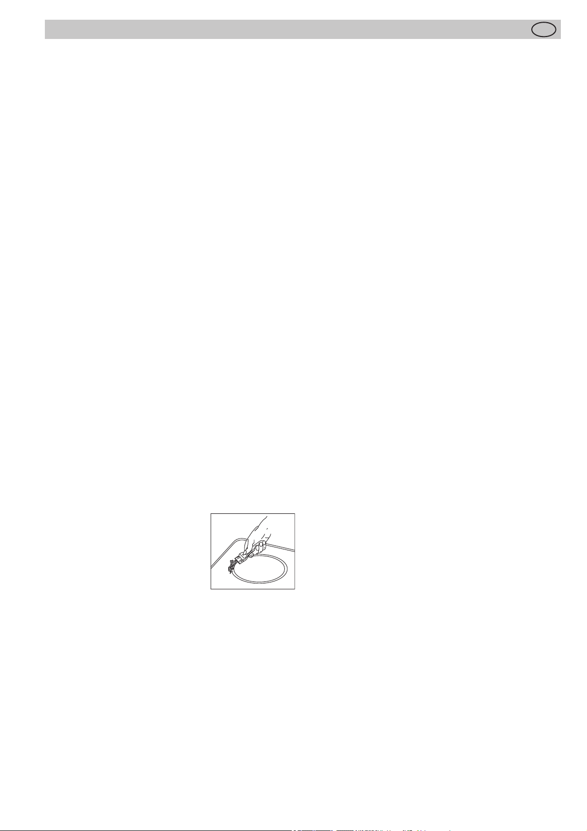
5.3 Kochmulden Lüfter
Reinigung der Metallfettfi lter
Reinigen Sie die Metallfettfi lter mindestens einmal im
Monat oder bei Überfettung und intensiver Nutzung im
Geschirrspüler oder in milder Spüllauge.
Zur Filterentnahme die Abdeckung des Lüfters abheben
und das U-förmige Edelstahl-Luftleitblech in der Ansaugöff nung nach oben aus dem Lüfter heben. Jetzt den Filter
entnehmen. Drücken Sie dazu die Verriegelung in der
Griff muschel nach unten und entnehmen Sie die Filter.
Die Filter können Sie im Geschirrspüler reinigen. Die Filter
im Geschirrspüler senkrecht stellen. Bitte verwenden Sie
ausschließlich aluminiumverträgliche Klarspüler, um Schäden und Verfärbungen an den Filtern zu vermeiden.
Nicht direkt neben Gläser oder hellem Porzellan spülen
lassen.
Betreiben Sie den Lüfter nicht ohne Fettfi lter!
Nach der Filter-Reinigung den Filter trocken wieder in den
Lüfter einsetzen. Bitte achten Sie darauf: Die Griff muschel
muss nach dem Einsetzen sichtbar sein. Wischen Sie
möglichst bei jedem Filterwechsel das leicht zugängliche
Lüfterinnere mit einem mit Spülmittel befeuchtetem Tuch
aus und achten Sie aber dabei auf hervorstehende Teile
im Inneren des Lüfters
Reinigung und Pfl ege des Lüfters
Am besten reinigen Sie den Lüfter mindestens bei jeder
Filterreinigung.
Nach intensivem Verkochen von Wasser mit geöff netem
Topfdeckel kann sich Kondenswasser unter dem Filter ansammeln. Das ist völlig normal. Das Wasser sollte jedoch
entfernt und das Lüfterinnere gereinigt werden.
Die Lüftungsöff nungen in der Abdeckung sorgen dafür,
dass aus dem Lüfter-Inneren auch im Ruhezustand mit
aufgesetzter Abdeckung ohne laufendes Gebläse gegebenenfalls Restfeuchtigkeit vom Kochen und Reinigen
entweichen kann.
Sollten dabei störende Restgerüche austreten, reinigen
Sie bitte den Filter und das Lüfterinnere.
Den Lüfter reinigen sie am besten mit einem feuchten,
weichen Tuch und milder Spüllauge.
Service
Der Filter muss zugänglich bleiben. Bei einem Aktivkohlefi lter alle 5 - 24 Monate die Kohlefi ltermatten tauschen.
23
Page 24
Was tun bei Problemen?
D
6 Was tun bei Problemen?
Unqualifi zierte Eingriff e und Reparaturen am Gerät sind
gefährlich, weil Stromschlag- und Kurzschlussgefahr
besteht. Sie sind zur Vermeidung von Körperschäden
und Schäden am Gerät zu unterlassen. Deshalb solche
Arbeiten nur von einem Elektrofachmann, wie z.B. einem
Technischen Kundendienst, ausführen lassen.
Bitte beachten
Sollten an Ihrem Gerät Störungen auftreten, prüfen Sie
bitte anhand dieser Gebrauchsanleitung, ob Sie die Ursachen nicht selber beheben können.
Nachfolgend fi nden Sie Tipps zur Behebung von Störungen.
Die Sicherungen lösen mehrfach aus?
Rufen Sie einen Technischen Kundendienst oder einen
Elektroinstallateur!
Das Induktionskochfeld lässt sich nicht einschalten?
• Hat die Sicherung der Hausinstallation (Sicherungskasten) angesprochen?
• Ist das Netzanschlusskabel angeschlossen?
• Sind die Sensortasten verriegelt (Verriegelung)?
• Sind die Sensortasten durch ein feuchtes Tuch, Flüssigkeit oder einen metallischen Gegenstand teilweise
bedeckt? Bitte entfernen.
• Wird falsches Geschirr verwendet? Siehe Kapitel „Geschirr für Induktionskochfeld”.
Das Symbol
grenzter Dauersignalton.
Es liegt eine Dauerbetätigung der Touch-Control Sensortasten durch übergekochte Speisen, Kochgeschirr oder
andere Gegenstände vor.
Abhilfe: die Oberfl äche reinigen oder den Gegenstand
entfernen. Zum Löschen des Symbols
betätigen oder das Kochfeld aus- und einschalten.
Der Fehlercode E2 wird angezeigt?
Die Elektronik ist zu heiß. Den Einbau des Kochfeldes
prüfen, speziell auf gute Belüftung achten.
Siehe Kapitel Überhitzungsschutz. Siehe Kapitel Belüftung.
Der Fehlercode E8 wird angezeigt?
Fehler am Lüfter rechts oder links. Die Ansaugöff nung ist
blockiert bzw. abgedeckt oder der Lüfter ist defekt.
Den Einbau des Kochfeldes prüfen, speziell auf gute Belüftung achten.
Siehe Kapitel Überhitzungsschutz. Siehe Kapitel Belüftung.
blinkt und es ertönt ein zeitlich be-
die gleiche Taste
Der Fehlercode U400 wird angezeigt?
Das Kochfeld ist falsch angeschlossen. Die Steuerung
schaltet nach 1s ab und es ertönt ein Dauersignalton. Die
richtige Netzspannung anschließen.
Es wird ein Fehlercode (ERxx oder Ex) angezeigt?
Es liegt ein technischer Defekt vor. Bitte den Kundendienst
rufen.
Es erscheint das Topfzeichen
Eine Kochzone wurde eingeschaltet und das Kochfeld
erwartet das Aufsetzen eines geeigneten Topfes (Topferkennung). Erst dann wird Leistung abgegeben.
Das Topfzeichen erscheint weiter, obwohl ein Kochgefäß aufgesetzt wurde?
Das Kochgefäß ist für Induktion ungeeignet oder es hat
einen zu kleinen Durchmesser.
Die verwendeten Kochgefäße geben Geräusche ab?
Diese Geräusche kommen aus dem Kochgeschirr durch
die Beschaff enheit des Pfannenbodens. Diese Geräusche
können je nach Art des verwendeten Kochgeschirrs und
der Menge der darin enthaltenen Lebensmittel unterschiedlich sein.
Das Kühlgebläse läuft nach dem Ausschalten nach?
Das ist normal, weil die Elektronik abgekühlt wird.
Das Kochfeld gibt Geräusche ab (Klick- bzw. Knackgeräusch)?
Das ist technisch bedingt und lässt sich nicht vermeiden.
Das Kochfeld hat Risse oder Brüche?
Bei Brüchen, Sprüngen, Rissen oder anderen Beschädigungen an der Glaskeramik besteht Stromschlaggefahr.
Das Gerät sofort außer Betrieb setzen. Sofort die Haushalts-Sicherung ausschalten und den Kundendienst rufen.
Pulsierendes Kochverhalten?
Die Induktionsheizkörper können Ihre Leistung nur bis zu
einer bestimmten Kochstufe herunter regeln. Unterhalb
dieser Kochstufe fängt der Heizkörper an zu Takten.
Das bedeutet, dass der Induktionsheizkörper abhängig
von der gewählten Kochstufe in einer bestimmten Zeit einund wieder ausschaltet. Dieses Taktverhalten ist hörbar
und wird beim Kochen durch Aufsteigen und Versiegen
von Bläschen am Topfboden sichtbar. Das pulsierende
Kochverhalten bei bestimmten Kochstufen ist normal und
hat keine negativen Auswirkungen auf das Kochergebnis.
Abhilfe: Möglichst auf Töpfe und Pfannen mit starkem
Topfboden und somit guter Wärmespeicherung und Verteilung achten. Kochtöpfe nach Möglichkeit immer mit einem
passenden Deckel verschließen. Beim Kochen ohne
Deckel geht sehr viel Energie verloren.
?
24
Page 25
Kundendienst
7 Kundendienst
Bevor Sie den Kundendienst anrufen:
1. Versuchen Sie, die Störung selbst zu beheben (s. „Störung - Was tun?”)
2. Schalten Sie das Gerät aus und wieder ein, um festzustellen, ob die Störung erneut auftritt.
Falls die Störung nach den vorstehend beschriebenen
Kontrollen weiter besteht oder erneut auftritt, rufen Sie
bitte den Kundendienst an.
Geben Sie dabei stets an:
• eine kurze Fehlerbeschreibung.
• Gerät und Modellnummer;
• Servicenummer (d. h. die Zahl nach dem Wort SERVICE auf dem Typenschild) auf der Unterseite der
Kochmulde oder im Blatt zur Produktbeschreibung.
Die Servicenummer ist auch auf dem Garantieschein
angegeben.
• Ihre vollständige Anschrift und Telefonnummer mit
Vorwahl
D
25
Page 26

Content
GB
1 Safety instructions and warnings ............................27
2 Instructions for assembly .........................................30
2.1 Safety instructions for kitchen unit fi tters ...............30
2.2 Ventilation ..............................................................30
2.3 Installation ..............................................................30
2.4 Variable installation possibilities:
Overlying installation .............................................31
2.5 Variable installation possibilities:
Flush installation ...................................................31
2.6 Illustrations kitchen cupboard. ...............................32
2.7 Extraction air system assembly .............................33
2.8 Important notes for fi tting .......................................34
2.9 7-pole fan plug connector ......................................35
2.10 4-pole plasma fi lter plug connector (optional) .....35
2.11 Hob fan installation...............................................36
2.12 Technical data ......................................................37
2.13 Putting the appliance into operation ....................37
3 Appliance description ...............................................38
3.1 Operating the hob with the sensor keys ................39
4 Operation ....................................................................40
4.1 The induction hob ..................................................40
4.2 Pan recognition .....................................................40
4.3 Operation time limit ................................................40
4.4 Other functions.......................................................40
4.5 Protection against overheating (induction) ............40
4.6 Cookware for induction hobs .................................41
4.7 How to cut power consumption .............................41
4.8 Power settings .......................................................41
4.9 Residual heat display ............................................41
4.10 Switching the appliance into the standby mode ..42
4.11 Operating the keys ...............................................42
4.12 Switching on the hob and cooking zones ............42
4.13 Switching off a cooking zone ...............................42
4.14 Switching off the hob ...........................................42
4.15 Lock......................................................................43
4.16 Automatic switch-off (timer) ................................44
4.17 Minute minder (egg timer) ...................................44
4.18 Power boost .........................................................45
4.19 Bridging function .................................................45
4.20 Power management ............................................45
4.21 Using the fan ........................................................46
4.21.1 Switching the fan on and off .............................46
4.21.2 Fan time lag ......................................................46
4.21.3 Stop delay time ................................................46
5 Cleaning and care ......................................................47
5.1 Glass ceramic hob .................................................47
5.2 Specifi c soiling .......................................................47
5.3 Hob fan ..................................................................47
6 What to do if trouble occurs? ...................................48
7 Customer Service ......................................................49
THANK YOU FOR BUYING A BAUKNECHT PRODUCT
In order to receive a more complete assistance, please
register your product on www.bauknecht.eu/ register
Before using the appliance carefully read the Safety Instruction .
26
Page 27
Safety instructions and warnings
GB
1 Safety instructions and warnings
IMPORTANT TO BE READ AND OBSERVED
Download the complete instruction manual on
docs.bauknecht.eu or call the phone number
shown on the warranty booklet.
Before using the appliance, read these safety
instructions. Keep them nearby for future reference.
These instructions and the appliance itself
provide important safety warnings, to be observed at all times. The manufacturer declines
any liability for failure to observe these safety
instructions, for inappropriate use of the appliance or incorrect setting of controls.
Very young children (0-3 years) should be
kept away from the appliance. Young children
(3-8 years) should be kept away from the appliance unless continuously supervised. Children from 8 years old and above and persons
with reduced physical, sensory or mental capabilities or lack of experience and knowledge
can use this appliance only if they are supervised or have been given instructions on safe
use and understand the hazards involved.
Children must not play with the appliance.
Cleaning and user maintenance must not be
carried out by children without supervision.
WARNING: The appliance and its accessible
parts become hot during use. Care shoul be
taken to avoid touching heating elements.
Children less than 8 years of age must be
kept away unless continuously supervised.
CAUTION: Accessible parts of the hood may
become hot when used with cooking appliances.
WARNING: If the hob surface is cracked,
don’t use the appliance – risk of electrical
shock.
WARNING: Danger of fi re: Do not store items
on the cooking surfaces.
CAUTION: The cooking process has to be
supervised. A short cooking process has to be
supervised continuously.
WARNING: Unattended cooking on a hob with
or oil can be dangerous – risk of fi re. NEVER
try to extinguish a fi re with water, but switch
off the appliance and then cover fl ame e.g.
with a lid or a fi re blanket.
Do not leave frying pans unattended when
frying, as the frying oil may catch fi re.
Do not use the hob as a work surface or
support. Keep clothes or other fl ammable
materials away from the appliance, unitl all the
components have cooled down completely –
risk of fi re.
Metallic objects such as knives, forks, spoons
and lids should not be placed on the hob surface since they can get hot.
After use, switch off the hob element by its
control and do not rely on the pan detector.
PERMITTED USE
CAUTION: the appliance is not intended to be
operated by means of an external switching
device, such as a timer, or separate remote
controlled system.
This appliance is intended to be used in
household and similar applications such as:
staff kitchen areas in shops, offi ces and other
working environments; farm houses; by clients
in hotels, motels, bed & breakfast and other
residential environments.
This appliance is not for professional use. Do
not use the appliance outdoors.
27
Page 28

Safety instructions and warnings
GB
INSTALLATION
The appliance must be handled and installed
by two or more persons - risk of injury. Use
protective gloves to unpack and install - risk of
cuts.
Installation, including water supply (if any)
and electrical connections, and repairs must
be carried out by a qualifi ed technician. Do
not repair or replace any part of the appliance
unless specifi cally stated in the user manual.
Keep children away from the installation site.
After unpacking the appliance, make sure that
it has not been damaged during transport. In
the event of problems, contact the dealer or
your nearest After-sales Service. Once installed, packaging waste (plastic, styrofoam parts
etc.) must be stored out of reach of children risk of suff ocation. The appliance must be disconnected from the power supply before any
installation operation - risk of electrical shock.
During installation, make sure the appliance
does not damage the power cable - risk of fi re
or electrical shock. Only activate the appliance when the installation has been completed.
Carry out all cabinet cutting works before fi tting the appliance in the furniture and remove
all wood chips and sawdust.
If the appliance is Not installed above an
oven, a separator panel (not included) must
be installed in the compartment under the
appliance.
The premises where the appliance is installed must be suffi ciently ventilated, when the
kitchen hood is used together with other gas
combustion devices or other fuels.
Exhaust air must not be vented through a fl ue
used for removal of fumes produced by appliances burning gas or other fuels, but must
have a separate outlet. All national regulations
governing extraction of fumes must be observed.
28
Page 29
Safety instructions and warnings
GB
ELECTRICAL WARNINGS
It must be possible to disconnect the appliance from the power supply by unplugging it if
plug is accessible, or by a multi-pole switch installed upstream of the socket in accordance
with the wiring rules and the appliance must
be earthed in conformity with national electrical safety standards.
Do not use extension leads, multiple sockets
or adapters. The electrical components must
not be accessible to the user after installation.
Do not use the appliance when you are wet
or barefoot. Do not operate this appliance if it
has a damaged power cable or plug, if it is not
working properly, or if it has been damaged or
dropped.
If the supply cord is damaged, it must be
replaced with an identical one by the manufacturer, its service agent or similarly qualifi ed
persons in order to avoid a hazard - risk of
electrical shock.
WARNING! Failure to install the screws or
fi xing device in accordance with these instructions may result in electrical hazards.
Earthing of the appliance is compulsory. (Not
necessary for class II hoods identifi ed by the
symbol ( ) on the specifi cations label).
CLEANING AND MAINTENANCE
WARNING: Ensure that the appliance is
switched off and disconnected from the power
supply before performing any maintenance
operation; never use steam cleaning equipment - risk of electric shock.
Do not use abrasive or corrosive products,
chlorine-based cleaners or pan scourers.
The hood must be regularly cleaned on both
the inside and outside (AT LEAST ONCE
A MONTH). This must be completed in accordance with the maintenance instructions
provided in this manual.
Failure to observe the instructions for cleaning
the hood and replacing the fi lters may result in
a fi re.
DECLARATIONS OF CONFORMITY
This appliance meets the energy label requirements of the
European Commission Regulation (EU) No 65/2014 supplementing Directive 2010/30/EU of the European Parliament and of the Council and the Ecodesign requirements
of the European Commission Regulation(EU) N°66/2014
implementing Directive 2009/125/EC; in conformity to the
European standard EN 61591 and EN 60704-2-13
29
Page 30
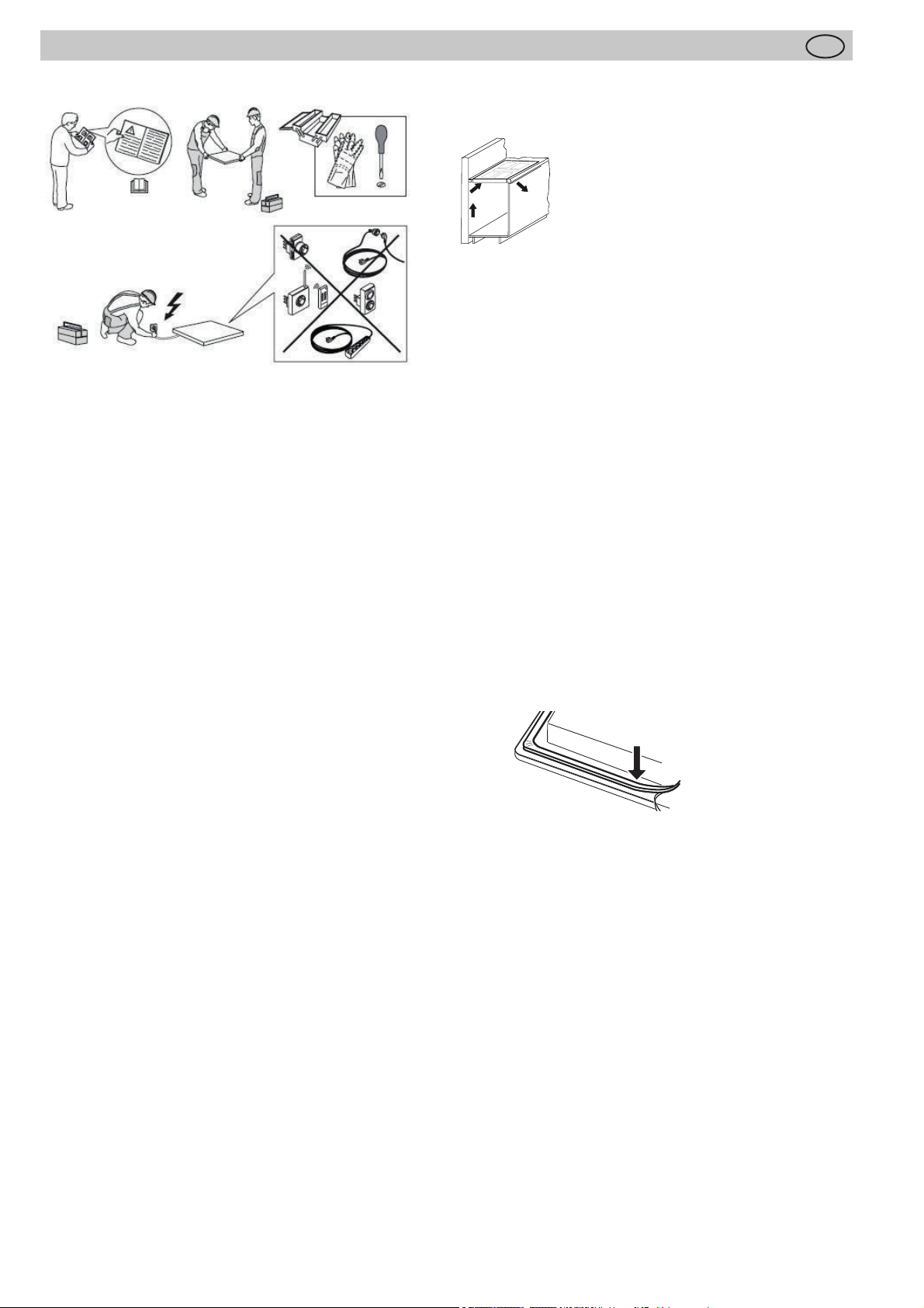
Instructions for assembly
GB
2 Instructions for assembly
2.1 Safety instructions for kitchen unit fi tters
• The appliance must be handled and installed by two or
more persons - risk of injury. Use protective gloves to
unpack and install - risk of cuts.
• Veneers, adhesives and plastic surfaces of surrounding
furniture must be temperature resistant (at least 75°C).
If the veneers and surfaces are not suffi ciently heat
resistant they may become deformed.
• Ensure that all live connections are safely insulated
when installing the hob.
• Cover strips between the wall and the worktop behind
the hob which are made of solid wood are permissible
as long as minimum clearances in accordance with the
installation diagrams are maintained.
• Minimum clearances of the hob cut-out towards the
rear are to be maintained in accordance with the installation diagram.
• For installation directly next to a tall cupboard, a safety
distance of at least 50 mm must be ensured. The side
surface of the tall cupboard should be fi tted with heat
resistant material. Due to working requirements, however, the distance should be at least 300 mm.
• The clearance between the hob and an extraction
hood must be at least as large as that stipulated in the
assembly instructions for the cooker hood.
• The packaging materials (plastic foil, polystyrene, nails
etc.) must be kept out of reach of children as these
parts are potentially dangerous. Small parts can be
swallowed and there is a danger of plastic sheeting
causing suff ocation.
2.2 Ventilation
• The induction hob is fi tted with a fan that switches on
and off automatically. The fan starts slowly when the
electronic system temperatures exceed a specifi c limit.
When the induction hob is used intensively, the fan will
switch to a greater velocity. Once the electronic system
has cooled down suffi ciently, the fan will reduce its
velocity and switch off again automatically.
• Clearance between the induction hob and kitchen furniture or built-in units must provide for suffi cient ventilation of the induction hob.
• If the power level of a cooking zone is automatically raised or lowered (see section on thermal cut-off device) it
is likely that the cooling system does not cool suffi ciently. In this case we recommend that the back wall of the
bottom kitchen unit in the area of the worktop cut-out
be opened and that the front transverse strip of the unit
be removed over the entire width of the appliance in
order to promote the circulation of air.
In order to better ventilate the hob, an air
gap of 5 mm should be left at the front.
2.3 Installation
Important information
• Installation, including water supply (if any) and electrical
connections, and repairs must be carried out by a qualifi ed technician. Do not repair or replace any part of the
appliance unless specifi cally stated in the user manual.
• Avoid excessive thermal development from below e.g.
from a baking oven without a cross fl ow cooling device.
• The induction hob may not be used when pyrolysis
operation is taking place in a built-in oven.
• If the appliance is not installed above an oven, a
separator panel (not included) must be installed in the
compartment under the appliance at least 20mm.
• The hob may not be installed above refrigerators, freezers, dishwashers, washing machines or dryers.
• To avoid danger of fi re, make sure that no combustible
objects which could easily catch fi re or become deformed on exposure to heat are directly next to or under
the surface.
• The front panel of 170 mm must be inserted. It may
only be removed with tools.
Sealing of the hob
Before installation, correctly insert the sealing unit delivered with the hob.
• No liquids may penetrate between the edge of the hob
and the worktop or between the hob and the wall and
come into contact with any electrical appliances.
• When installing a hob into an uneven worktop, e.g. with
a ceramic or similar covering (tiles etc.), the seal on the
hob is to be removed and the seal between the hob
and worktop made with plastic sealing materials (putty).
• The hob must under no circumstances be sealed with
silicone sealant! This would make it impossible to remove the hob at a later date without damaging it.
Working surface cut-out
Cut out the worktop recess accurately with a good, straight
saw blade or recessing machine. The cut edges should
then be sealed so that no moisture can penetrate.
The area is cut out as illustrated. The glass ceramic hob
must have a level and fl ush bearing. Any distortion may
lead to fracture of the glass panel. Make sure that the sealing of the hob is properly seated.
30
Page 31

Instructions for assembly
p
GB
2.4 Variable installation possibilities:
Overlying installation
Dimensions in mm
4
4
R5
min.50
Minimum distance to adjacent walls
Opening dimensions
Cutout dimensions
Outer dimensions of the hob
1
2
800
750+1
1
520
500+1
2 4
min.50
2.5 Variable installation possibilities:
Flush installation
R7
3
min.50
Glue the sealing tape onto the corner of the supporting
edge of the worktop so that no silicone adhesive can be
pressed under the hob.
Place the hob into the worktop cut-out without any adhesive and align it. Use shims if necessary
Fill the gap between the hob and the worktop with heat-resistant silicone adhesive.
1
804+1
2
750+1
3
500+1
524+1
3
2
min.50
1
166
46
Important
Silicone adhesive must not get under the support surface.
If this occurs it will not be possible to remove the hob again
at a later stage. No liability will be assumed in the case of
4
60
120
84 x 455
90
failure to observe these instructions.
3
50
4,5 -0,5
170
120
84 x 455
64
90
31
Page 32

2.6 Illustrations kitchen cupboard.
600-mm worktop
40
170
40
Instructions for assembly
GB
100
min.
96
140
255
max.430
max.430
max.300
Exhaust outlet on the left
Exhaust outlet on the right
600
≥335
165
NW150
NW150
800
≥170
≥150220
Option of outgoing air on the left or right: Depending
on installation, left or right can be chosen for outgoing
air Please note the dimensions shown opposite for
optimal planning.
≥370
100
min.
170
96
Worktop
>120
140
255
>600 mm
Exhaust outlet on the left
max. 430
max. 430
max. 430
40
≥335
≥170165
NW150
NW150
≥680
800
Option of outgoing air on the left or right: Depending
on installation, left or right can be chosen for outgoing
air Please note the dimensions shown opposite for
optimal planning.
≥150220
≥370
32
Exhaust outlet on the right
Page 33

Instructions for assembly
GB
2.7 Extraction air system assembly
The hob and the fan can be connected with a fl exible hose
or a fl at duct.
Shorten the fl at duct with a fi ne saw if necessary.
Option fl exible hose
Option fl at
duct
Exhaust air duct components (optional):
*
*
On point c
The fl exible connection piece is used for a worktop thickness of 600 mm. Please make sure that installation is as
taut and crease-free as possible by shortening excess
material.
On point f
Apply sealing tape to the plinth fan connecting pieces (f)
before attaching the adapter piece (d) to the plinth fan (e).
Important:
The components must all be fi rmly fastened as shown with
the adhesive tape enclosed after they have been attached.
Fan
Sealing tape
Plinth fi lter (optional):
Charcoal fi lter
h
Plasmafi lter
33
Page 34

Instructions for assembly
GB
2.8 Important notes for fi tting
• The appliance must be handled and installed by two or
more persons - risk of injury. Use protective gloves to
unpack and install - risk of cuts.
• Keep children away from the installation site.
• After unpacking the appliance, make sure that it has
not been damaged during transport. In the event of
problems, contact the dealer or your nearest After-sales
Service.
• Once installed, packaging waste (plastic, styrofoam
parts etc.) must be stored out of reach of children - risk
of suff ocation.
• The appliance must be disconnected from the power
supply before any installation operation - risk of
electrical shock. During installation, make sure the
appliance does not damage the power cable - risk of
fi re or electrical shock. Only activate the appliance
when the installation has been completed.
• Carry out all cabinet cutting works before fi tting the
appliance in the furniture and remove all wood chips
and sawdust.
• If the appliance is Not installed above an oven, a
separator panel (not included) must be installed in the
compartment under the appliance.
• The cross-section of wall vents and the cut-out in the
base panel should should at least correspond to the
exhaust air pipe. The outfl ow opening must be at least
500 cm². Reduce the height of the skirting boards or
make corresponding openings.
• When installing the appliance make sure that the convection air unit is still accessible when the kitchen has
been completely installed. If necessary levelling feet for
the kitchen units must be moved.
• The hob fan can be operated in the extraction air and
recirculation air mode.
• Lead the outgoing air outside through a ventilation shaft
intended for this purpose or through the wall of the
building.
• Outgoing air may not be led into a smoke or exhaust
gas fl ue which is in operation. Contact the district master chimney sweep if you are in any doubt.
• A suffi cient supply of inlet air must be provided if a
wood, coal, gas or oil heater requiring a chimney is
operated in the environment of the hob fan, since an
insuffi cient supply of air results in a risk of poisoning.
The safe operation of the hob fan is guaranteed when
the negative pressure resulting from the hob fan does
not exceed 0.04 mbar (4 Pa) and a suffi cient supply of
inlet air can fl ow into the room.
• Exhaust air pipes must comply with fi re class B 1 DIN
4102. Please make sure that the minimum nominal
width of the appliance connecting pieces is not reduced.
• A system recommended for the airfl ow and compatible with the hob extractor should always be used.
• The nominal width of the recirculation air pipe should
not be less than 150 mm.
• Exhaust air pipes should be as short as possible. They
should not have a 90-degree angle; instead they should
have soft bends and no reductions in their cross-section.
• Never use pipes with a diameter of less than 150 mm.
No bends/ angles may be laid 50 cm before the fan
module.
• Always insert a straight piece of approx. 50 cm between two angles/bends.
Assembly
• Please observe the generally valid power plant and fi re
authority requirements.
• Installation/connection by qualifi ed staff members
• No claims for damage caused by failure to observe
this document and/or the documents enclosed with the
appliance may be enforced against the manufacturer.
• Observe minimum clearances to walls: on the side at
least 100 mm and at the back at least 50 mm.
Preparing the table cut-out
• Mill around the cut-out or produce it with strips of wood.
• Cut-outs accurate to dimension and right-angled.
• Ensure the correct height, so that the hob and the fi lter
unit fi t exactly.
• Take recess ventilation of at least 400 cm2 into account
on the side.
• Units and covers must be temperature-resistant (<
75°C).
• Only plan for the fi lter set to be on the left.
Installing the fan unit
• Place the unit (charcoal or plasma) into the niche.
• Align the air vents, fasten.
• Establish an electrical connection.
• Insert the hob, align.
• Do not operate the hob while the silicone is hardening.
• Test the primer/adhesive for usability before gluing.
• Do not screw the hob tight as it weighs 18 kg (fi lter not
included).
• Combustible walls/ceilings above hobs must be fi tted
with fi re-resistant cladding according to the relevant fi re
department organs.
Connecting to the electric power supply
• Only switch the safety fuses/main switch on once the
hob has been installed/wired.
• Mount the enclosed sign in a clearly visible position
since this will no longer be accessible after installation.
• Combustible walls/ceilings above hobs must be fi tted
with fi re-resistant cladding according to the relevant fi re
department organs.
• Install the hob properly to ensure its protection against
accidental contact.
• The charcoal or plasma fi lter must be installed so that it
is always conveniently and easily accessible for servicing purposes.
PLEASE NOTE
When the convection air mode is in operation, ventilation must be suffi cient in order for
the air humidity to be removed.
34
Page 35

Instructions for assembly
GB
2.9 7-pole fan plug connector
Procedure
Connect the two 7-pole plus for the fan connection.
Open the plug retainer on the 7-pole plug (fan) of the hob
and attach the 7-pole fan mating connector (e) until it is
securely engaged. Then close the plug retainer again.
After installation, fi t the connectors on the rear panel or in
the shelf unit.
e
2.10 4-pole plasma fi lter plug connector (optional)
Procedure
Open the plug connections on the 4-pole plug (plasma) of
the hob and remove the protective covers. Attach the plug
to the 4-pole mating plug of the plasma fi lter (g) until it has
fi rmly engaged.
Then close the plug retainer again.
After installation, fi t the connectors on the rear panel or in
the shelf unit.
• When connecting the appliance it must be ensured that
there is a device which makes it possible to universally
disconnect it from the mains with a contact opening
width of at least 3mm. Line-protecting switches, fuses
or contactors are suitable cut-out devices. When
connecting and repairing the appliance disconnect it
from the electricity supply with one of these devices.
• The earth wire must be suffi ciently long so that if the
strain relief fails, the live wires of the connecting cable
are subjected to tension before the earth wire.
• Any superfl uous cable must be removed from the installation area beneath the appliance.
• Make sure that the local mains voltage is the same as
the voltage on the rating label.
• Full protection against accidental contact must be ensured on installation.
• Attention: Incorrect connection may result in the power
electronics unit being destroyed.
• The appliance is only authorised for permanent
connection. It may not be connected with a shock-proof
plug.
Mounting the metal cover for the plugs
h
WARNING OF ELECTRICAL ENERGY!
RISK OF FATAL INJURY!
Live components have been installed
near this symbol. Covers bearing this sign
may only be removed by a certifi ed skilled
electrician.
• The electrical connection must be carried out by a
qualifi ed electrician who is authorised to carry out such
work!
• Statutory regulations and the connection specifi cations
issued by the local power supply company must be
strictly observed.
Fix the bottom chassis at the wall (screws not included)
Insert the plugs with cable protection rubbers
Close the cover with the 4 screws (supplied)
Even if one of the connectors shown in the fi gures above
is not used, make sure that it is also inserted into the metal
box.
35
Page 36

Instructions for assembly
GB
2.11 Hob fan installation
• The product may only be connected by a qualifi ed fi tter
according to applicable local regulations. The same
applies for the extraction air connections. The fi tter is
responsible for proper functioning at the installation
site.
• On installation, observe the relevant national building
regulations and the regulations of the electricity suppliers.
• The hob fan can be operated in the extraction air and
recirculation air mode.
• Lead the outgoing air outside through a ventilation shaft
intended for this purpose or through the wall of the
building.
• Outgoing air may not be led into a smoke or exhaust
gas fl ue which is in operation. Contact the district master chimney sweep if you are in any doubt.
• A suffi cient supply of inlet air must be provided if a
wood, coal, gas or oil heater requiring a chimney is
operated in the environment of the hob fan, since an
insuffi cient supply of air results in a risk of poisoning.
The safe operation of the hob fan is guaranteed when
the negative pressure resulting from the hob fan does
not exceed 0.04 mbar (4 Pa) and a suffi cient supply of
inlet air can fl ow into the room.
• Exhaust air pipes must comply with fi re class B 1 DIN
4102.
• Please make sure that the minimum nominal width of
the appliance connecting pieces is not reduced.
• A system recommended for the airfl ow and compatible
with the hob extractor should always be used.
• The nominal width of the recirculation air pipe should
not be less than 150 mm.
• Exhaust air pipes should be as short as possible. They
should not have a 90-degree angle; instead they should
have soft bends and no reductions in their cross-section.
• Never use pipes with a diameter of less than 150 mm.
No bends/angles may be laid 50 cm before the fan
module.
• Always insert a straight piece of approx. 50 cm between two angles/bends.
• The cross-section of wall vents and the cut-out in the
base panel should should at least correspond to the
exhaust air pipe. The outfl ow opening must be at least
500 cm². Reduce the height of the skirting boards or
make corresponding openings.
• When installing the appliance make sure that the convection air unit is still accessible when the kitchen has
been completely installed.
• If necessary levelling feet for the kitchen units must be
moved.
Power supply
Mains voltage: 380-415V 3N~, 50/60Hz
Component rated voltage: 220-240V
Mains cable available in the factory
• The hob has been fi tted with a temperature-resistant
connection cable in the factory.
• Connection to the mains is carried out in accordance
with the circuit diagram, unless the connection cable is
already fi tted with a plug.
• If the mains cable of this appliance is damaged it will
need to be replaced with a special connection cable. In
order to avoid any risks, this must be carried out by the
manufacturer or his Customer Service.
Electrical connections
380-415 V 3N~
grey
black
brown
L2
L1
L1
black
L2
L3
brown
L3
grey
blue
N
white
N
blue
380-415 V 2N~
black
green-yellow
L1
380-415 V 2N~380-415 V 3N~
black
brown
green-yellow
L1
grey
brown
L2
grey
L2
blue
N
white
N
green-yellow
220-240 V 1N~
blue
black
green-yellow
220-240 V 1N~
blue
grey
black
brown
grey
brown
N
white
N
L1
L1
green-yellow
blue
green-yellow
36
PLEASE NOTE
When the convection air mode is in
operation, ventilation must be suffi cient in
order for the air humidity to be removed.
Page 37

Instructions for assembly
GB
2.12 Technical data
Hob dimensions
height/ width/ depth ...mm 170 x 800 x 520
Cooking zones
Front (left) . . . . Ø cm / kW
rear (left) . . . . Ø cm / kW
rear right . . Ø cm / kW
front right . . . Ø cm / kW
Hob ..............................kW
Fan ..............................kW
Plasma .......................kW
* Power when the power boost function is activated
19 x 21 / 1.6 (1.85)*
19 x 21 / 2.1 (3.00)*
19 x 21 / 1.6 (1.85)*
19 x 21 / 2.1 (3.00)*
7.4
0.115
0.01
2.13 Putting the appliance into operation
Once the hob has been installed and the power supply has
been provided (mains connected) an automatic test of the
controls will be carried out and information for Customer
Service will be indicated.
Important: No items may be on the touch control sensor
keys when the appliance is being connected!
Briefl y wipe over the surface of the hob with a sponge and
soapy water and then dry with a clean cloth.
37
Page 38

3 Appliance description
Appliance description
GB
The decorative design may deviate from the illustrations.
1. Induction cooking zone front left
2. Induction cooking zone back left
3. Glass ceramic hob
4. Touch-Control panel
5. Standby key and fan controls
6. Fan
7. ON / OFF key (hob)
8. Cooking zone selection key
9. Symbol for locating the position of a cooking zone on
the glass ceramic hob
10. Plus key (raise) / Minus key (lower)
11. Power setting indicator
12. Timer indicator
13. Standby key
14. Minus key /Plus key Ventilation
15. Fan indicator
38
Page 39

Appliance description
GB
3.1 Operating the hob with the sensor keys
The glass ceramic hob is operated with touch control sensor keys. The sensor keys are operated as follows: lightly
touch a symbol on the surface of the ceramic glass plate. A
buzzer will indicate when the controls have been operated
correctly.
The touch control sensor key will then be indicated as
“key”.
Standby key
This key is used to switch the entire hob operational. It is,
as it were, the main switch. When the hob has been switched off with this key, it will remain on standby for approx.
another 120 min.
Attention! The residual heat indicator will no longer operate
when the appliance has completely switched off .
ON/OFF key (7) Cooking zones left or right
This key is used to switch the respective cooking hob side
left or right on and off .
Cooking zone selection key; e.g. front (8)
Pressing one of the cooking zone selection keys available
will select a cooking zone, for which the Plus key or the
Minus key may be used to set the cooking level.
(13)
Power setting display (11)
The power setting indicator shows the power setting which
has been selected, or:
lights up brightly Cooking zone has been selected
........................................... Residual heat
........................................... Power boost
............................................ Locking
........................................... Bridging function
ER03 .....................................Error message
Control lamp .................. Timer function
Minus key /Plus key Ventilation (14)
These key are used to operate the fan (extractor fan). It
can be operated independently of the hob.
Fan indicator (15)
.................Fan setting
................Fan time lag
Minus key / Plus key (10)
These keys are used to set the cooking levels, the automatic switch-off device and the minute minder.
The Minus key reduces the setting and the Plus key raises
it.
39
Page 40

Operation
GB
4 Operation
4.1 The induction hob
The hob is equipped with an induction cooking mode. An
induction coil underneath the glass ceramic hob generates
an electromagnetic alternating fi eld which penetrates the
glass ceramic and induces the heat-generating current in
the pot base.
With an induction cooking zone the heat is no longer
transferred from a heating element through the cooking pot
into the food being cooked; instead the necessary heat is
generated directly in the container by means of induction
currents.
Advantages of the induction hob
• Energy-saving cooking through the direct transfer of
energy to the pot (suitable pots/pans made of magnetisable material are required).
• Increased safety as the energy is only transferred when
a pot is placed on the hob.
• Highly eff ective energy transfer between an induction
cooking zone and the base of a pot.
• Rapid heat-up.
• Food which boils over does not stick to the surface.
• Rapid, sensitive control of the energy supply.
4.2 Pan recognition
If a cooking zone is switched on and there is no pan on
the zone or if the pan is too small, there will be no transmission of power. A blinking in the power level indicator
points this out.
If a suitable pot or pan is placed on the cooking zone, the
power setting will switch on and the power setting indicator
will light up. The power supply will be cut off when the pan
is removed and the power setting indicator will indicate a
blinking .
If the pots and pans placed on the cooking zone are of
smaller dimension, and the pan recognition still switches
on, less power will be supplied.
Pan recognition limits
Cooking zone diameter
(mm)
190 x 210 mm 120
The base of pots and pans must be of a certain diameter;
if it is not, the induction heat will not be switched on. Always place pots and pans in the middle of a cooking zone
in order to achieve the best effi ciency.
Important: The minimum diameter required to activate the
pan recognition device may vary according to the type of
pot or pan used!
Recommended minimal
diameter pan base (mm)
4.3 Operation time limit
The induction hob has an automatic time limit function.
The duration of continuous use of each cooking zone de-
pends on the cooking level selected (see chart).
This requires that the setting of a respective cooking zone
is not adjusted during use.
If the operation time limit has been activated, the cooking
zone will switch off , a short signal will sound and an H will
appear in the display.
The automatic switch-off function overrules the operation
time limit, i.e. the cooking zone is only switched off when
the period of time of the automatic switch-off device has
expired (e.g. automatic switch-off after 99 minutes and
cooking level 9 is possible).
Operation time limit
Selected cooking level Operation time limit in hours
1, 2
3, 4
5
6, 7, 8, 9
6
5
4
1.5
4.4 Other functions
If two or more sensor keys are pressed at the same time
(e.g. when a pan is mistakenly put onto a sensor key) no
function will be activated.
An acoustic signal sounds and ER03 will appear. After a
few seconds the appliance will switch off . Please remove
the item located in front of the sensor keys.
4.5 Protection against overheating (induction)
If the hob is used at full power for a longer period, it will not
be possible to cool down the electronics system as required at a high room temperature.
In order to ensure that no excessive temperatures occur
in the electronics system the power of the cooking zones
may be reduced automatically.
Should E2 or ER21 be displayed frequently during normal
use of the hob and at normal room temperature, it is likely
that cooling is not suffi cient.
This may occur if kitchen units have no openings. The
installation may have to be checked (see the section on
Ventilation).
40
Page 41

Operation
GB
4.6 Cookware for induction hobs
Cookware for induction cooking zones must be made of
metal and have magnetic properties. The base must be
suffi ciently large.
Only use pots with a base suitable for induction.
Suitable cookware Unsuitable cookware
Enamelled steel pots with a
thick base
Cast iron pots with an enamelled base
Pots made of multi-layer
stainless steel, stainless
ferrite steel and aluminium
with special base
This is how to establish the suitability of a pot:
Conduct the magnet test described below or make sure
that the pot bears the symbol for suitability for cooking with
induction current.
Magnet test:
Move the magnet towards the base of
your cookware. If it is attracted, you can
use the cookware on the induction hob.
Pots made of copper,
stainless steel, aluminium,
oven-proof glass, wood,
ceramic and terracotta
4.7 How to cut power consumption
The following are a few useful hints to help you cut your
consumption of energy and use your new induction hob
and the cookware effi ciently.
• The base of your cooking pots should be the same size
as the cooking zone.
• When buying cooking pots, note that it is frequently the
diameter of the top of the pot that it indicated. This is
usually larger than the base of a pot.
• Pressure cookers are particularly low on energy and
time required thanks to the pressure and the fact that
they are tightly closed. Short cooking times mean that
vitamins are preserved.
• Always make sure that there is suffi cient fl uid in your
pressure cooker since the cooking zone and the cooker
may be damaged as a result of overheating if the pressure cooker boils dry.
• Always close cooking pots with a suitable lid.
• Use the right pot for the quantity of food you are cooking. A large pot which is hardly fi lled will use up a lot of
energy.
4.8 Power settings
The heating power of the cooking zones can be set at
various power levels. In the chart you will fi nd examples of
how to use each setting.
Please note:
When using pans suitable for induction from certain manu-
facturers, noises may occur which are attributable to the
design of these pans.
Wrong: the base of the pan is curved. The electronic unit
cannot determine the temperature correctly.
Setting Suitable for
0
1-2
3
4-5
6
7-8
9
P
A higher power level may need to be selected for cooking
pots without a lid.
Off , using residual heat
Simmering small portions
Simmering level
Simmering larger quantities or roasting
larger pieces of meat until they are cooked through
Roasting, getting juices
Roasting
Bringing to the boil, browning, roasting
Power boost (highest power output)
4.9 Residual heat display
The glass ceramic hob is equipped with an H as a residual
heat indicator.
As long as the H lights up after the cooking zone has been
switched off , the residual heat can be used for melting food
or for keeping food warm.
The cooking zone may still be hot when the letter H no
longer lights up.
The glass ceramic is not directly heated in the case of an
induction cooking zone; it is only heated up by heat refl ected by the pan.
41
Page 42

Suitable for induction cooking
Cooking zone selection key
Operation
4.10 Switching the appliance into the standby mode
This standby key is used to switch the entire hob operational. It is, as it were, the main switch. An automatic test of the
controls will be carried out fi rst of all, and the displays will light
up briefl y.
When the hob has been switched off with this key, it will remain on standby for approx. another 120 min.
Attention! The residual heat indicator will no longer operate
when the appliance has completely switched off .
4.11 Operating the keys
The controls described here expect the pressing of a (selection) key to be followed by the pressing of a subsequent key.
The next key will need to be pressed within 10 seconds,
otherwise the selection will be deleted.
The Plus/ Minus keys can be touched individually or be permanently pressed.
4.12 Switching on the hob and cooking zones
1. Press the ON/OFF key of the hob (1 s.) until the power
setting 0 appears. The controls are ready for operation.
2. Then press a cooking zone selection key (e.g. for
front). The selected power setting display will light up
brightly.
3. Use the Plus key or Minus key to select a power
setting. The plus key will activate power setting 1 and the
minus key power setting 9.
4. Immediately put cookware suitable for induction cooking
onto the cooking zone. The pan recognition device will activate the induction coil. The pot or pan will be heated up.
As long as no cooking pot is placed onto the cooking zone,
the display will alternate between the power level set and
the symbol . If no pot is placed on the cooking zone it will
switch off after 10 minutes for reasons of safety. Please
refer to the Section on pan recognition.
Repeat items 2 to 4 in order to cook on other cooking
zones at the same time.
GB
42
4.13 Switching off a cooking zone
5. Press the required cooking zone selection key (e.g.
for front). The selected power setting indicator will light up
brightly.
6. a) Press the Minus key
setting indicator shows 0 or
b) Press the On/Off key of the hob . The entire hob will
be switched off (all the cooking zones are switched off ).
several times until the power
4.14 Switching off the hob
7. Press the ON/Off key of the hob . The hob will be switched off , irrespective of any settings.
Page 43

Operation
4.15 Lock
The lock serves to prevent children from switching on the
hob accidentally or intentionally. The controls are blocked
here.
Activating the lock
1. Press the ON/OFF key
hob.
2. Then immediately press the Minus key and the right
cooking zone selection key simultaneously.
3. Then press the same cooking zone selection key in
order to activate the lock.
The power setting indicators will show an L for child
lock, the controls will be disabled and the hob will
switch off .
Switching off the lock
4. Press the ON/Off key of the hob .
5. Then immediately press the Minus key and the right
cooking zone selection key simultaneously.
6. Then press the Minus key in order to deactivate the
lock. The L will go off .
GB
in order to switch on the
De-activating the lock for one cooking procedure only
This is only possible if the lock has been switched on
according to points 1-3.
• Press the ON/Off key of the hob .
• Then immediately press the Minus key and the right
cooking zone selection key simultaneously.
Once the L has gone off , the user may switch a cooking zone on.
When the hob is switched off the lock will be activated
again (switched on).
Please note
In the event of a power cut the lock will not be cancelled,
i.e. it remains activated.
43
Page 44

Setting for 5 minutes
Operation
4.16 Automatic switch-off (timer)
The automatic switch-off device is used to automatically
switch off any cooking zone after an adjustable period of
time. Cooking times ranging from 01 to 99 minutes can
be set.
1. Switch on the hob. Switch on one or more cooking
2. Repeatedly press the Plus key
3. Then immediately press the Plus key or the Minus
4. The cooking zone will be switched off when the time
GB
zones and select the required power settings.
and the Minus key
simultaneously until the control lamp (decimal
point) of the cooking zone of your choice lights up.
The timer indicator will light up brightly.
key to enter the cooking time.
In order to programme the automatic switch-off device
for another cooking zone, repeatedly press the Plus
key and the Minus key simultaneously until the
control lamp (decimal point) of the respective power
level display lights up.
has lapsed. A signal will sound for a while and can be
switched off by pressing any key (except the ON/OFF
key).
Control lamp (decimal point)
Notes
• In order to check on the time that has lapsed (automatic switch-off device), repeatedly press the Plus
key and the Minus key simultaneously until the
control lamp (decimal point) of the respective cooking
zone lights up. The setting displayed can be read and
changed.
• Terminating the function of the timer: Select the respective cooking zone and use the Minus key to set 0.
4.17 Minute minder (egg timer)
(cooking zone switched off )
1. Switch on the hob.
2. Press the Plus key and the Minus key simultaneously once. The timer indicator will light up brightly.
The control lamp (decimal point) may not light up in
the cooking setting displays.
3. Then immediately use the Plus key or the Minus
key to set the time in minutes.
4. Once the time has lapsed a signal will sound for a
while and can be switched off by pressing any key
(except the OFF key).
44
Setting for 12 minutes
Please note
• The minute minder will also remain in operation when
the right or left side of the hob is switched off . Switch
the left or right side of the hob on to adjust the time.
Page 45

Operation
4.18 Power boost
The power boost setting makes additional power available
for induction cooking zones. A large quantity of water can be
brought to the boil very quickly. The power boost setting operates for 5 minutes, after which the power level is automatically reduced to power setting 9.
1. Switch on the hob.
2. Then press a cooking zone selection key (e.g..
back). The selected power setting indicator will light up
brightly.
3. Press the Minus key once in order to set the highest
power setting 9.
4. Press the Plus key once in order to activate the power
boost setting. The power setting indicator will show a P.
5. After 5 minutes the power boost setting will switch off automatically. The P will go off and the power level will switch
down to 9.
Notes
• Press the minus key to prematurely de-activate the power
setting.
• Attention. risk of overheating! Do not heat up any oil/
frying fat with the power boost setting.
GB
for
Modules (power management)
4.19 Bridging function
The front and the rear cooking zones may be activated together for a cooking process (bridging function). This enables
larger cookware to be used.
1. Switch on the hob.
2. Press the two cooking zone selection keys of the front
and back cooking zones simultaneously to activate the
bridging function.
The bridging function is activated, the symbol appears.
Use the Plus key or Minus key to select a power
setting.
3. To deactivate the two cooking zone selection keys press
them simultaneously again or switch off the hob.
Notes
The roaster or the pot will need to cover at least half of the
cooking zones used in order to be recognised by the pan
recognition device!
4.20 Power management
For technical reasons two cooking zones always comprise a
module and have a maximum power level.
If this power range is exceeded when a higher power setting
level or the power boost function is switched on the power
management system will reduce the power setting of the corresponding cooking zone of the module.
The display for this cooking zone will initially blink, after which
the highest-possible power setting will be consistently displayed.
45
Page 46

Operation
4.21 Using the fan
The fan is located in the middle of the hob with the extractor
facing downwards.
Important:
Do not put the cover onto the induction hob! Risk of bur-
ning!
4.21.1 Switching the fan on and off
1. Press the standby key
2. Press the fan Plus key (1 s.).
You will then be able to select a power setting, 1,2,3 or 4, by
using the Plus or Minus key . The symbol for the fan
will light up.
The intensive power setting 4 operates for 10 minutes, after
which the power level is automatically reduced to power
setting 3.
3. Press the fan Minus key until 0 is shown in order to
switch fan off .
Hint
In order to ensure that extraction functions well with tall cooking
pots (e.g. pots used for cooking asparagus), you can place a
wooden spoon under the lid of the pot.
(approx. 1 s.).
GB
4.21.2 Fan time lag
The fan time lag is used after cooker in order to remove cooking
odours. The fi lter is also dried in the fan.
Setting the fan time lag
1. Press simultaneously the fan Plus key and Minus key .
The fan time lag of 10 minutes will be activated. The symbol
for the fan time lag will light up .
2. Pressing simultaneously again the Plus- and Minus key
will set 60 minutes.
3. The time lag function is deactivated by pressing the two keys
simultaneously again.
The fan setting can be freely adjusted or changed when the fan
time lag is switched on.
4.21.3 Stop delay time
The fan motor should continue operating for another 10-20 minutes every time the hob has been used for cooking. When the
fan is switched off after having been in operation for at least 15
minutes, an automatic time lag at a low setting will follow for
around 15 minutes.
This guarantees optimal functioning and the removal of remaining cooking steam.
When using a recirculating air fi lter, please always allow for a
stop delay time of 10 - 60 minutes in order to optimally remove
cooking odours.
When the fan is switched on again, in rare cases the odour molecules present in the fi lter may be combined with steam so that
they are detected again. These remaining odours will disappear
when the fan continues to operate.
Important
When the convection air mode is in operation, ventilation must
be suffi cient in order for the air humidity to be removed.
46
Page 47

Cleaning and care
GB
5 Cleaning and care
• Switch the hob off and let it cool down before you clean
it.
• Never clean the glass ceramic hob with a steam cleaner or similar appliance!
• When cleaning make sure that you only wipe lightly
over the ON/OFF key. The hob may otherwise be accidentally switched on!
5.1 Glass ceramic hob
Important! Never use aggressive cleaning agents such as
rough scouring agent, abrasive saucepan cleaners, rust
and stain removers etc.
Cleaning after use
1. Always clean the entire hob when it has become soiled.
It is recommended that you do so every time the hob
is used. Use a damp cloth and a little washing up liquid
for cleaning. Then dry the hob with a clean dry cloth to
ensure that there is no detergent left on the surface of
the hob.
Weekly cleaning
2. Clean the entire hob thoroughly once a week with commercial glass ceramic cleaning agents. Please follow
the manufacturer's instructions carefully. When applied,
the cleaning agent will coat the hob in a protective fi lm
which is resistant to water and dirt. All the dirt will remain on the fi lm and can then easily be removed. Then
rub the hob dry with a clean cloth. Make sure that no
cleaning agent remains on the surface of the hob since
this will react aggressively when the hob is heated up
and will change the surface.
5.2 Specifi c soiling
Heavy soiling and stains (limescaling and shiny, mo-
ther-of-pearl-type stains) can best be
removed when the hob is still slightly
warm. Use commercial cleaning
agents to clean the hob. Proceed as
outlined under Item 2.
First soak food which has boiled
over with a wet cloth and then remove
remaining soiling with a special glass
scraper for glass ceramic hobs. Then clean the hob again
as described under Item 2.
Burnt sugar and melted plastic must be removed immediately, when they are still hot, with a glass scraper. Then
clean the hob again as described under Item 2.
Grains of sand which may get onto the hob when you
peel potatoes or clean lettuce may scratch the surface of
the hob when you move pots around. Make sure that no
grains of sand are left on the hob.
Changes in the colour of the hob will not aff ect the function and the stability of the glass ceramic material. These
colour changes are not changes in the material but food
residues which were not removed and which have burnt
into the surface.
Shiny spots result when the base of the cookware rubs
on the surface of the hob, particularly when cookware
with an aluminium base or unsuitable cleaning agents are
used. They are diffi cult to remove with standard cleaning
agents. You may need to repeat the cleaning process
several times. In time, the decoration will wear off and dark
stains will appear as a result of using aggressive cleaning
agents and faulty pan bases.
5.3 Hob fan
Cleaning the metal grease fi lters
Clean the metal grease fi lters in the dishwasher or in
mild soapy water at least once a month or in the event of
excessive grease deposits and/or intensive use.
To remove the fi lter, lift up the fan cover and lift the U-shaped stainless steel ventilation plate in the suction intake
opening upwards to remove it from the fan. Now remove
the fi lter. To do so, press the lock in the recessed handle
downwards and remove the fi lter.
The fi lter can be rinsed in a dishwasher. Stand the fi lter
upright in the dishwasher. Please use only rinse aid that is
suitable for use with aluminium in order to avoid damaging
and discolouring the fi lters.
Never rinse right next to glasses or light-coloured porcelain.
After rinsing the fi lter, dry it and replace it in the fan. Please
make sure that the recessed handle is visible after you
have replaced the fi lter. If possible, wipe the easily accessible inside of the fan with a cloth dampened with detergent every time you replace a fi lter, while at the same time
paying attention to protruding parts in the inside of the fan.
Fan cleaning and care
The fan is best cleaned every time you clean the fi lters.
Condensation water may collect under the fi lter after water
has boiled rapidly with the lid of the pot removed. This is
quite normal. The water should, however, be removed and
the inside of the fan cleaned.
The ventilation openings in the cover ensure that residual
moisture resulting from cooking and cleaning can escape
if necessary when the fan is not in operation and the cover
is on.
Please clean the fi lter and the inside of the fan if unpleasant remaining odours escape.
The fan is best cleaned with a soft damp cloth and mild
soapy water.
Service
The fi lter must remain accessible. Replace the charcoal
fi lter mats of a charcoal fi lter every 5 to 24 months.
Replace the charcoal fi lter mats of plasma fi lters at least
every 5 years. To do so, open the cover of the casing and
replace the charcoal fi lter mats.
47
Page 48

What to do if trouble occurs?
GB
6 What to do if trouble occurs?
Interference with and repairs to the appliance by unqualifi ed persons are dangerous as they can result in an electric shock or a short circuit. Do not interfere with or try to
repair the appliance; this could cause injury to persons and
damage to the appliance. Always have such work done by
an expert, e.g. a Customer Service technician.
Please note
If your appliance is faulty, please check whether you can
rectify the problem yourself by consulting these instructions for use.
You may be able to rectify some problems yourself.
They are described below.
The fuses blow regularly?
Contact a technical customer service or an electrician!
You can't switch your induction hob on?
• Has the wiring system (fuse box) in the house blown a
fuse?
• Has the hob been connected to the mains?
• Are the sensor keys locked (lock)?
• Are the sensor keys partly covered by a damp cloth,
fl uid or a metallic object? Please rectify.
• Are you using unsuitable cookware? See the section on
"Cookware for induction hobs".
Error code U400 is indicated?
The hob has been incorrectly connected. The controls will
switch off after 1sec. and a continuous signal will sound.
Connect the appliance to the appropriate power supply.
An error code (ERxx or Ex) is indicated?
The appliance has developed a technical defect. Please
call Customer Service.
The pot sign
A cooking zone has been switched on and the hob is expecting a suitable pot or pan to be placed on the cooking
zone (pan recognition). Only when a pot has been placed
on the cooking zone will power be supplied.
The pot sign still appears, even though a pot or pan
was placed on the hob?
The cookware is unsuitable for induction cooking or the pot
or pan is too small.
Is the cookware you are using making noises?
These noises actually come from the cookware and are
linked to the characteristics of the pan bottoms.
These noises may vary according to the type of cookware
used and to the amount of food it contains.“
Does the cooling fan still operate after it has been
switched off ?
This is normal since the electronic unit is being cooled
down.
appears?
The symbol
signal will sound.
Food which has boiled over, cookware or other items are
causing the touch control sensor keys to be consistently
operated.
Remedy: clean the surface or remove the item. To delete
the symbol
and on.
Error code E2 is indicated?
The electronic unit is too hot. Check the installation of the
hob. Make sure that there is suffi cient ventilation.
See the section on “Protection against overheating”. See
the section on “Ventilation”.
Error code E8 is indicated?
Fault on the left or right fan. The suction opening is blocked or covered or the fan is defect.
Check the installation of the hob. Make sure that there is
suffi cient ventilation.
See the section on “Protection against overheating”. See
the section on “Ventilation”.
will blink and a time-limited continuous
press the same key or switch the hob off
Is the hob making noises (clicking or cracking
sounds)?
This is for technical reasons and cannot be avoided.
Does the hob have tears or cracks?
There is a risk of electric shocks if the glass ceramic hob
develops fractures, cracks, tears or damage of any other
kind. Immediately switch off the appliance. Disconnect the
fuse immediately and call Customer Service.
Pulsating cooking?
The induction heating elements can only switch their power down to a certain power setting. The heating element
will start to clock below this power setting.
This means that the induction heating element will switch
on and then off again at certain intervals irrespectively of
the selected power setting. This clocking can be heard and
will become visible when you are cooking through bubbles
forming on the bottom of the pan and then disappearing
again. This pulsating cooking is normal at certain power
levels and will not have any negative eff ect on the results
of cooking.
Remedy: Make sure that pots and pans have a thick base
so that they have good heat retention and distribution properties. Always close cooking pots with a suitable lid. A lot
of energy is lost when cooking pots without a lid are used.
48
Page 49

Customer Service
7 Customer Service
Before you phone Customer Service:
1. Try to rectify the problem yourself (see "What to do if
trouble occurs?.")
2. Switch your appliance off and on again to fi nd out
whether the problem occurs again.
Please phone Customer Service if the problem continues or occurs again after you have carried out the checks
described above.
Always state the following:
• Short type of fault/fault description
• Appliance and model number
• Service number (i.e. the number following the word
SERVICE on the nameplate) on the bottom of the hob
or on the sheet with the product specifi cation.
The service number is also shown on the warranty
certifi cate.
• Your full address and telephone number, including your
area code
GB
49
Page 50

Table des matières
F
1 Consignes de sécurité et avertissements...............51
2 Instructions de montage ...........................................54
2.1 Consignes de sécurité pour l’installateur
des meubles de cuisine ........................................54
2.2 Ventilation ..............................................................54
2.3 Montage .................................................................54
2.4 Possibilités variables de montage :
Montage posé .......................................................55
2.5 Possibilités variables de montage :
Montage à surface plane ......................................55
2.6 Illustrations Armoire de cuisine ..............................56
2.7 Assemblage du système d'évacuation d'air ..........57
2.8 Instructions importants de montage ......................58
2.9 Connecteur 7 pôles Raccordement ventilateur .....59
2.10 Connecteur 4 pôles
Raccordement fi ltre au plasma ............................59
2.11 Ventilateur de table de cuisson ............................60
2.12 Caractéristiques techniques ................................61
2.13 Mise en service ....................................................61
3 Description de l’appareil ...........................................62
3.1 Commande par touches sensitives .......................63
4 Utilisation ....................................................................64
4.1 La table de cuisson à induction .............................64
4.2 Détection des récipients .......................................64
4.3 Limitation de la durée de fonctionnement .............64
4.4 Autres fonctions .....................................................64
4.5 Protection en cas de surchauff e (induction) ..........64
4.6 Vaisselle pour table de cuisson à induction ...........65
4.7 Conseils pour économiser de l’énergie .................65
4.8 Positions de cuisson ..............................................65
4.9 Indicateur de chaleur résiduelle ............................65
4.10 Commuter l'appareil prêt à l'emploi .....................66
4.11 Utilisation des touches .........................................66
4.12 Mettre en marche la table de cuisson
et la zone de cuisson ...........................................66
4.13 Arrêter la zone de cuisson ...................................66
4.14 Arrêter la table de cuisson ...................................66
4.15 Verrouillage ..........................................................67
4.16 Arrêt automatique (minuterie) .............................68
4.17 Minuterie (sablier) ................................................68
4.18 intensité «Power» ................................................69
4.19 Fonction de pontage ...........................................69
4.20 Powermanagement .............................................69
4.21 Utiliser le ventilateur ............................................70
4.21.1 Mettre en marche et arrêter le ventilateur ........70
4.21.2 Arrêt temporisé du ventilateur ...........................70
4.21.3 Durée d'arrêt temporisé ...................................70
5 Nettoyage et entretien ...............................................71
5.1 Table de cuisson vitrocéramique ...........................71
5.2 Salissures résistantes ............................................71
5.3 Ventilateur de table de cuisson ..............................71
6 Que faire en cas de problèmes ? .............................72
7 Service Après Vente ..................................................73
MERCI D'AVOIR ACHETÉ UN APPAREIL DE LA MARQUE BAUKNECHT
Afi n de bénéfi cier d'un service après-vente complet, veuillez enregistrer votre produit à l'adresse www.bauknecht.
eu/
Veuillez impérativement lire les consignes de sécurité
avant la mise en service de votre appareil.
50
Page 51

Consignes de sécurité et avertissements
F
1 Consignes de sécurité et avertissements
IMPORTANT !
Lisez et téléchargez le mode d'emploi entier
à l'adresse docs.bauknecht.eu ou appelez
le numéro de téléphone mentionné dans la
déclaration de garantie.
Lisez soigneusement les informations portées
dans ce manuel avant de mettre votre table
de cuisson en service.
Respectez toujours toutes les consignes de
sécurité de ce mode d'emploi, ainsi que celles
apposées sur l'appareil. Le fabricant ne peut
être considéré comme responsable des dommages entraînés par des erreurs d'utilisation,
le non-respect des consignes de sécurité et
des réglages incorrects.
Les enfants de moins de 3 ans ne doivent rester sans surveillance à proximité de l'appareil.
Les enfants de moins de 8 ans doivent rester
à l'écart de l'appareil, sauf s'ils se trouvent
sous surveillance permanente. Cet appareil
ne doit pas être utilisé par des personnes (y
compris des enfants à partir de 8 ans), avec
des capacités physiques, sensorielles ou
mentales limitées ou manquant d’expérience et/ou de connaissances, à moins qu’elles
soient surveillées par une personne responsable de leur sécurité ou qu’elles aient reçu
des instructions de la part de cette personne,
comment utiliser l’appareil. Veillez à ce que
les enfants ne puissent pas jouer avec l'appareil. Maintenir les enfants à l'écart de l'appareil
pendant les opérations de nettoyage et de
maintenance.
ATTENTION : Les pièces accessibles de
l'appareil se réchauff ent énormément pendant l'utilisation de l'appareil. Veillez à ne pas
toucher les pièces brûlantes. Les enfants de
moins de 8 ans doivent rester à l'écart de l'appareil, sauf s'ils se trouvent sous surveillance
permanente.
PRUDENCE : Les pièces accessibles de la
table de cuisson se réchauff ent pendant l'utilisation.
ATTENTION : Risque de choc électrique en
cas de brisure, de fi ssure ou d'autres endommagements de la surface en verre.
ATTENTION : Risque d’incendie ! Ne vous
servez pas de la surface vitrocéramique pour
y déposer des objets.
PRUDENCE : Toujours surveiller chaque procédure de cuisson, courte ou longue.
ATTENTION : La préparation des plats avec
de la graisse ou de l'huile doit toujours se
faire sous surveillance - Risque d'incendie.
Ne jamais éteindre les feux de graisse avec
de l'eau ! Arrêter l’appareil et recouvrir les
fl ammes avec précaution, p. ex. à l’aide d’un
couvercle ou d’une couverture anti-feu.
Ne laissez jamais sans surveillance des plats
remplis de graisse de friture ou d'huile, l'huile
brûlante peut s'enfl ammer spontanément.
N'utilisez jamais la table de cuisson comme
surface de rangement ! Les matériaux infl ammables, p. ex. les vêtements, doivent être
tenus à l'écart de l'appareil jusqu'à ce que les
zones de cuisson soient complètement refroidies – RISQUE D'INCENDIE.
Veillez à ne pas poser d'objets en métal tels
que les couteaux, les fourchettes, les cuillères
et les couvercles sur la table de cuisson, car
ils pourraient devenir très chauds.
Après l'utilisation, arrêter la zone de cuisson impérativement avec la manette et non
uniquement par la détection du récipient de
cuisson.
UTILISATION CONFORME À L’USAGE
PRÉVU
PRUDENCE : L'appareil ne doit pas être
commandé par l'intermédiaire d'appareils de
commutation externes, comme minuteries ou
télécommande séparée.
Cet appareil est destiné aux cuisines domestiques et pour l'utilisation dans des installations similaires, comme cuisines du personnel
dans les magasins, les bureaux et autres
environnements de travail, dans les entreprises agricoles et pour l'utilisation par les clients dans des hôtels, motels, pensions avec
petit-déjeuner et autres environnements à
caractéristiques d'habitat.
L’appareil n’est pas destiné à un usage professionnel. N'utilisez pas l'appareil à l'air libre.
51
Page 52

Consignes de sécurité et avertissements
F
INSTALLATION
L’appareil doit toujours être déplacé et encastré
par au moins deux personnes - risque d’accident ! Lors du déballage et de l’encastrement,
portez toujours des gants de protection avec
d’éviter des blessures par coupures.
Le montage, y compris le raccordement à
l'alimentation en eau (si nécessaire) doit être
réalisé uniquement pas un technicien qualifi é.
Ne réparez ou ne remplacez aucune pièce
d'appareil, même si cela devait être décrit expressément dans le mode d'emploi.
Tenir les enfants éloignés du lieu d'installation.
Après avoir retiré l'appareil de son emballage,
veuillez contrôlez l'absence d'éventuels dommages dûs au transport. En cas de problèmes,
veuillez vous adresser à un revendeur ou à
votre service après-vente le plus proche. Une
fois l’encastrement terminé, enlevez tous les
déchets d’emballage (plastiques, pièces en
mousse, etc.), et les conserver hors de portée
des enfants - risque d’asphyxie. Avant le montage, coupez l'appareil de l'alimentation électrique
- risque d'électrocution. Lors de l’encastrement, assurez-vous que le câble secteur n’est
pas endommagé - risque d’incendie et risque
d’électrocution. N'allumez l'appareil que si son
montage est entièrement achevé.
Exécutez tous les opérations de découpe des
meubles et plans de travail avant d'encastrer
les appareils, et retirez les copeaux.
Si l’appareil n’est PAS encastré au-dessus
d’un four, il faudra installer une paroi de séparation (non fournie) dans le meuble de cuisine
placé sous l’appareil.
Assurez une ventilation suffi sante lors de l'utilisation simultanée de l'appareil encastré avec
d'autres types de gaz ou d'autres sources de
cuisson.
L'évacuation d'air doit avoir lieu à extérieur
avec une conduite d'évacuation d'air prévue à
cet eff et ou en traversant le mur du logement.
Toutes les prescriptions nationales relatives
aux évacuations d'air de combustion et de
fumées doivent être respectées.
52
Page 53

Consignes de sécurité et avertissements
F
AVERTISSEMENTS ÉLECTRIQUES
L'appareil doit pouvoir être débranché du
secteur en débranchant la fi che du secteur
lorsque celle-ci est accessible ou par un interrupteur multipolaire installé devant la prise
conformément aux règles de câblage et l'appareil doit être mis à la terre conformément
aux normes nationales de sécurité électrique.
N'utilisez pas de rallonges, de prises multiples
ou d'adaptateurs. Les composants électriques
ne doivent pas être accessibles à l'utilisateur
après l'installation. Ne jamais utiliser l’appareil
en étant mouillé ou pieds nus. Ne jamais utiliser l'appareil lorsque le câble d'alimentation
électrique ou le connecteur est endommagé,
lorsqu'il ne fonctionne pas correctement ou
qu'il est endommagé ou a subi une chute.
Si le cordon d'alimentation est endommagé, il
doit être remplacé par un cordon identique par
le fabricant, son technicien de maintenance
ou tout autre personnel qualifi é afi n d'éviter
tout risque de choc électrique.
AVERTISSEMENT ! Si les vis ou le dispositif
de fi xation n’est pas monté conformément aux
indications de cette notice, ceci peut entraîner
des dommages électriques.
La mise à la terre de l'appareil est impérativement obligatoire. (Non requis pour les
boitiers de classe II marqués du symbole ( )
sur la plaque signalétique).
NETTOYAGE ET MAINTENANCE
ATTENTION : Avant toute intervention de
nettoyage et de maintenance, coupez l'appareil du réseau électrique ; ne jamais utiliser de
nettoyeurs à vapeur - risque d'électrocution.
N'utilisez aucun détergent abrasif, à base de
chlore ni d'éponges à récurer.
La hotte doit être nettoyée régulièrement à
l'intérieur et à l'extérieur (AU MOINS UNE
FOIS PAR MOIS) et ce, en conformité avec
les consignes de maintenance visées dans ce
mode d'emploi.
L'absence ou l'insuffi sance du nettoyage, ainsi que le non-respect des consignes, peuvent
entraîner l'apparition d'un incendie.
DÉCLARATIONS DE CONFORMITÉ
Cet appareil est conforme aux exigences en matière
d'étiquetage énergétique du règlement (UE) n° 65/2014
de la Commission européenne complétant la directive
2010/30/CE du Parlement européen et du Conseil et aux
exigences en matière d'écoconception du règlement (UE)
n° 66/2014 de la Commission européenne mettant en œuvre la directive 2009/125/CE ; conformément aux normes
européennes EN 61591 et EN 60704-2-13.
53
Page 54

Instructions de montage
F
2 Instructions de montage
• Si la puissance d’une zone de cuisson est souvent
2.1 Consignes de sécurité pour l’installateur des meubles de cuisine
• L’appareil doit toujours être déplacé et encastré par au
moins deux personnes - risque d’accident ! Lors du dé-
ballage et de l’encastrement, portez toujours des gants
de protection avec d’éviter des blessures par coupures.
• Les placages, colles ou revêtements plastiques des
meubles voisins doivent résister à la chaleur (75 °C au
minimum). Si les contreplacages et revêtements ne
sont pas suffi samment résistants aux hautes températures, ils risquent de se déformer.
• L’encastrement doit être réalisé de manière à
empêcher tout contact avec l’appareil.
• L’utilisation de baguettes de fi nition en bois massif
installées sur le plan de travail derrière la plaque de
cuisson est autorisée, à condition de respecter les distances minimum indiquées sur le schéma d’installation.
• Respecter impérativement les distances minimum de
découpe par rapport au mur arrière, en suivant scrupuleusement le schéma d’encastrement.
• En cas de montage directement à côté d’un meuble
haut, respectez une distance de sécurité d’au moins 50
mm. La paroi latérale du meuble doit être revêtue d’un
matériau thermorésistant. Pour des raisons techniques
de travail, la distance devrait être de 300 mm minimum.
• La distance entre la table de cuisson et une hotte aspirante doit être en conformité avec la notice de montage
de la hotte aspirante (distance minimum).
• Tenez les enfants éloignés du matériel d'emballage
(fi lms plastiques, Polystyrène, clous, etc.) ; celui-ci peut
représenter une source de danger. Les petites pièces
risquent d'être avalées et les fi lms plastiques peuvent
provoquer l'étouff ement.
2.3 Montage
Consignes importantes
• L’installation, y compris l’alimentation en eau (si exis-
• Éviter toute production de chaleur excessive sous la
• N'utilisez jamais la table de cuisson à induction lorsque
• Si l’appareil n’est PAS encastré au-dessus d’un four, il
• Le montage de la table de cuisson au-dessus d’ap-
• Pour éviter tout risque d'infl ammation, ne déposez ou
• Le bandeau frontal, long de 170 mm, doit être monté et
Joint d’étanchéité
Le joint d'étanchéité doit être mis en place avant l'encastrement.
2.2 Ventilation
• La zone de cuisson par induction dispose d'un ventilateur qui se déclenche et s'éteint automatiquement.
Lorsque les valeurs de température de l'électronique
dépassent un certain seuil, le ventilateur démarre à bas
régime. Si la zone de cuisson par induction est utilisé
de manière intensive, le ventilateur commute alors à
un régime supérieur. Le ventilateur réduit son régime
lorsque l'électronique est suffi samment refroidie et se
coupe automatiquement.
• L'écart entre la table de cuisson à induction et les
meubles de cuisine ou les appareils encastrés doit être
suffi sant, afi n d’assurer une ventilation suffi sante de la
table à induction.
• Éviter impérativement que du liquide puisse passer ent-
• Lors de l’encastrement d’une table de cuisson en vi-
réduite ou coupée de manière automatique (cf. le
chapitre « Protection en cas de surchauff e »), le refroidissement est vraisemblablement insuffi sant. Dans
ce cas, il est recommandé d’ouvrir la paroi arrière de
l’armoire basse dans la zone de la découpe de la table
de cuisson et de retirer la traverse frontale du meuble
sur toute la largeur de la table de cuisson afi n d’améliorer la circulation de l’air.
Une fente d'au moins 5mm est recommandée à l'avant pour faciliter la
ventilation de la zone de cuisson.
tante), ainsi que le raccordement électrique doivent
être eff ectués par un technicien qualifi é. Ne réparez ni
ne remplacez aucune pièce de l’appareil sauf si ceci
expressément décrit dans le mode d’emploi.
table de cuisson, provenant par exemple d'un four sans
ventilation tangentielle.
le four sous plan est en fonctionnement Pyrolyse.
faudra installer une paroi de séparation d'au moins 20
mm de largeur (non fournie) dans le meuble de cuisine
placé sous l’appareil.
pareils de réfrigération, d’un lave-vaisselle ou d’un
lave-linge ou d’un sèche-linge est interdit.
installez jamais des objets ou des produits facilement
infl ammables ou non résistants à la chaleur sous ou à
proximité de la table de cuisson.
ne pourra être enlevés qu’avec des outils.
re le bord de la table de cuisson et le plan de travail ou
entre le plan de travail et le mur et pénétrer ainsi dans
les appareils électriques situés en contrebas.
trocéramique dans un plan de travail irrégulier recouvert de céramique ou similaire (carrelage), le joint placé
sur la table de cuisson doit être enlevé et l'étanchement
de la table de cuisson par rapport au plan de travail doit
être réalisé à l'aide d'un produit d'étanchement souple
(mastic).
54
Page 55

Instructions de montage
p
F
2.4 Possibilités variables de montage :
Montage posé
Dimensions en mm
4
4
R5
min.50
Espacement minimal par rapport aux meubles at-
tenants
Dimensions de la découpe
Dimensions de fraisage
Dimensions hors tout de la table de cuisson
1
2
800
750+1
1
500+1
2 4
min.50
520
2.5 Possibilités variables de montage :
Montage à surface plane
R7
3
min.50
Coller le ruban d’étanchéité dans l’angle de la découpe du
plan de travail et ce, de telle sorte que la colle silicone ne
puisse pas pénétrer sous la table de cuisson.
Déposer la table de cuisson sans colle dans la découpe du
plan de travail et l'aligner. Le cas échéant, placer dessous
des cales de hauteur.
Combler l'espace entre la table de cuisson et le plan
de travail avec une colle silicone résistante aux hautes
températures.
1
2
804+1
750+1
3
500+1
524+1
3
2
min.50
1
166
46
Important !
La colle au silicone ne doit pénétrer à aucun endroit sous
la surface d’appui. Sinon il ne sera plus possible de retirer
la table de cuisson. Pas de garantie en cas de non-obser-
4
60
120
84 x 455
90
vation.
170
50
3
4,5 -0,5
120
84 x 455
64
90
55
Page 56

2.6 Illustrations Armoire de cuisine
Plan de travail 600 mm
40
170
40
Instructions de montage
F
100
min.
96
140
255
430 max
430 max
300 max
Sortie d'évacuation d'air à gauche
Sortie d'évacuation d'air à droite
600
≥335
165
NW150
NW150
800
≥170
≥150220
Évacuation d'air au choix à gauche ou à droite :
en fonction de la situation de montage, la position de l'évacuation d'air peut être à gauche ou à
droite. Pour une planifi cation optimale, respecter
ici les cotes ci-contre.
≥370
100
min.
170
96
Plan de travail
>120
140
255
> 600 mm
40
430 max
430 max
430 max
Sortie d'évacuation d'air à gauche
Sortie d'évacuation d'air à droite
≥680
≥335
≥170165
≥150220
NW150
NW150
800
Évacuation d'air au choix à gauche ou à droite :
en fonction de la situation de montage, la position de l'évacuation d'air peut être à gauche ou à
droite. Pour une planifi cation optimale, respecter
ici les cotes ci-contre.
≥370
56
Page 57

Instructions de montage
F
2.7 Assemblage du système d'évacuation d'air
Le raccordement de la table de cuisson au ventilateur peut
se faire avec une gaine fl exible ou un canal plat.
Raccourcir le cas échéant avec une scie fi ne la longueur
du canal plat.
Variante gaine fl exible
Variante
canal plat
Composants du conduit d'évacuation d'air (* pièces optionnelles, non comprises dans la livraison)
*
*
Au sujet du point c
Le raccord fl exible sera utilisé pour une profondeur de
plan de travail de 600 mm. Lors de la pose, veiller à une
installation si possible tendue et sans plis. Raccourcir ici le
matériau en surplus.
Au sujet du point f
Avant d'enfi cher la pièce intermédiaire (d) sur le ventilateur
de socle (e), placer du ruban d'étanchéité sur la tubulure
de raccordement du ventilateur de socle (f).
Important :
après l'assemblage, tous les composants doivent être
collés de manière étanche avec le ruban adhésif joint,
conformément à l'illustration.
Ventilateur
Ruban
d'étanchéité
Filtre de socle (option) :
Filtre à charbon actif
h
Filtre au plasma
57
Page 58

Instructions de montage
F
2.8 Instructions importants de montage
• L’appareil doit toujours être déplacé et encastré par
au moins deux personnes - risque d’accident ! Lors du
déballage et de l’encastrement, portez toujours des gants
de protection avec d’éviter des blessures par coupures.
• Toujours garder les enfants éloignées de la zone d’encastrement.
• Une fois l’appareil déballé, vérifi ez qu’il ne présente aucuns dommages dus au transport. En cas de problèmes,
veuillez vous adresser à un revendeur ou à votre service
après-vente le plus proche.
• Une fois l’encastrement terminé, enlevez tous les
déchets d’emballage (plastiques, pièces en mousse
etc.), et les conserver hors de portée des enfants - risque
d’asphyxie.
• Avant tout encastrement, débrancher l’appareil du réseau
électrique - risque d’électrocution. Lors de l’encastrement, assurez-vous que le câble secteur n’est pas
endommagé - risque d’incendie et risque d’électrocution.
N’utilisez l’appareil qu’une fois entièrement encastré.
• Tous les travaux de découpe dans des meubles ou des
plans de travail doivent être exécutés avant l’encastrement. Enlevez toutes les chutes de bois et tous les
copeaux.
• Si l’appareil n’est PAS encastré au-dessus d’un four, il
faudra installer une paroi de séparation (non fournie)
dans le meuble de cuisine placé sous l’appareil.
• Le diamètre des caissons maçonnés, ainsi que de la découpe dans le bandeau de socle, doit être d'un diamètre
au moins égal à celui de la conduite d'évacuation. Une
ouverture d'évacuation d'au moins 500 cm² doit être réalisée. Raccourcir la hauteur des bandeaux de socle ou y
pratiquer des orifi ces correspondants.
• Lors de l'installation, veiller à ce que le module d'évacuation reste accessible également après l'installation complète de la cuisine. Le cas échéant, les pieds de socle
des armoires de cuisine doivent être déplacés.
• Le ventilateur de table de cuisson peut être utilisé en
mode d'évacuation ou en mode de recirculation d'air.
• L'évacuation d'air doit avoir lieu à extérieur avec une conduite d'évacuation d'air prévue à cet eff et ou en traversant le mur du logement.
• L'évacuation d'air ne doit pas être amenée dans une
cheminée d'évacuation des fumées ou de gaz brûlés
déjà utilisées. En cas de doute, consulter le ramoneur
responsable de la zone d'habitation concernée.
• Si des foyers à cheminée sont utilisés à proximités du
ventilateur de table de cuisson (combustion de charbon,
de mazout ou de gaz), une ventilation suffi sante doit
alors être assurée sous peine de risque d'empoisonnement. Le fonctionnement inoff ensif de la table de cuisson
est assuré lorsque la dépression engendrée par le ventilateur de table de cuisson ne dépasse pas 0,04 mbar
(4 Pa) et qu'une quantité d'air suffi sante d'air peut s'écouler dans le local.
• Les conduites d'évacuation d'air doivent satisfaire aux
critères de la classe d'incendie B 1 DIN 4102. Veiller à ce
que le diamètre nominal intérieur des raccords d'évacuation de l'appareil ne soit pas réduit.
• Toujours utiliser le système recommandé et compatible
avec l'évacuation de table de cuisson.
• Le diamètre nominal intérieur des conduites d'évacuation
ne doit pas être inférieur à 150mm.
• Les conduites d'évacuation d'air doivent être aussi courtes que possible, ne pas présenter d'angles à 90°, mais
des coudes d'une angulation supérieure, ni de réductions
du diamètre.
• Ne jamais choisir de conduites dont le diamètre intérieur
est inférieur à 150mm. Aucun coude ne doit être positionné à moins de 50 cm du ventilateur.
• Toujours prévoir une section de tube d'env. 50 cm entre
deux coudes/angles.
Montage
• Veuillez observer les consignes générales de la compagnie d’électricité et de la police du feu.
• Montage / Raccordement par un professionnel.
• Tous dommages consécutifs à un non-respect des
présents documents ou des documents fournis avec
l’appareil ne sauraient faire l’objet d’une indemnisation
par le fabricant.
• Respecter les distances minimales par rapport au mur
: au moins 100 mm sur le côté et au moins 50 mm à
l’arrière.
Préparation de la découpe du panneau.
• Découper par fraisage ou réaliser avec des baguettes de
bois.
• Découpes sur mesure et à angle droit
• Assurer une hauteur suffi sante pour un encastrement
parfait de la table de cuisson et de l’unité fi ltrante
• Tenir compte d’une ventilation latérale de la niche sur au
moins 400 cm².
• Les meubles et les couvercles doivent résister à la chaleur (< 75 °C).
• Prévoir un set de fi ltres uniquement à gauche.
Encastrer l’unité de ventilateur
• Placer l’unité (charbon actif ou plasma).
• Orienter les prises d’air, les fi xer.
• Réaliser les raccordements électriques.
• Insérer la table de cuisson, la centrer.
• Ne pas faire fonctionner la table de cuisson pendant la
phase de prise du silicone.
• Avant d’encoller, tester l’utilisabilité du primer / de la
masse collante.
• Ne pas visser à fond la table de cuisson car il pèse 18 kg
(sans fi ltre).
• Les murs / plafonds infl ammables au-dessus des zones
de cuisson doivent être munis d’un habillage ignifuge
selon les consignes de l’organisme compétent de la
police du feu.
Branchement électrique
• N’enclencher les fusibles / l’interrupteur principal qu’après
l’encastrement / le câblage de la table de cuisson.
• Fixer l’écriteau fourni à un endroit bien visible, car il ne
sera plus accessible après encastrement.
• Les murs / plafonds infl ammables au-dessus des zones
de cuisson doivent être munis d’un habillage ignifuge
selon les consignes de l’organisme compétent de la
police du feu.
• Réaliser l’encastrement de manière à empêcher tout
contact avec la plaque de cuisson.
• Le fi ltre à charbon actif ou à plasma devra être installé de
manière à être toujours facilement accessible à des fi ns
d’entretien.
REMARQUE
En mode « Recyclage d'air », veiller à une
ventilation suffi sante afi n d'évacuer correctement l'humidité de l'air.
58
Page 59

Instructions de montage
F
2.9 Connecteur 7 pôles
Raccordement ventilateur
Procédure
Relier les deux connecteurs 7 pôles pour raccorder le
ventilateur. Ouvrir le protège-connecteur sur le connecteur
7 pôles (ventilateur) de la table de cuisson, brancher le
contre-connecteur 7 pôles du ventilateur (e) jusqu'à ce que
celui-ci s'enclenche sûrement. Ensuite, refermer le protège-connecteur.
Une fois l’installation terminée, il faudra fi xer les connecteur au panneau arrière ou un élément mural.
e
2.10 Connecteur 4 pôles
Raccordement fi ltre au plasma
Procédure
Ouvrir les connecteurs sur le collecteurs 4 pôles (plasma)
de la table de cuisson et retirer les couvercles de protection. Enfi cher ensuite le contre-connecteur 4 pôles du fi ltre
plasma (g) jusqu'à ce qu'il s'enclenche solidement.
Ensuite, refermer le protège-connecteur.
Une fois l’installation terminée, il faudra fi xer les connec-
teur au panneau arrière ou un élément mural.
h
• Lors du raccordement de l’appareil, prévoyez un
dispositif permettant d’isoler celui-ci du réseau avec
un intervalle de coupure d’au moins 3 mm sur tous les
pôles. Les commutateurs LS, les coupe-circuit et les
fusibles constituent des dispositifs de séparation adéquats. Lors de l’installation et des travaux de réparation, utilisez l’un de ces dispositifs pour mettre l’appareil
hors tension.
• Le fi l de terre doit être suffi samment long pour que, en
cas de rupture de la décharge de traction, ce fi l ne soit
soumis à la traction qu’après les câbles conducteurs
d’électricité.
• L’excédent de câble doit être retiré de l’espace en dessous de l’appareil.
• Veillez à ce que la tension secteur présente soit conforme à celle de l’étiquette.
• L’encastrement doit être réalisé de manière à
empêcher tout contact avec l’appareil.
• Attention : Un mauvais raccordement peut provoquer la
destruction de l’électronique de puissance.
• L'appareil est conçu uniquement pour un raccordement
fi xe. Il ne doit pas être raccordé par l'intermédiaire d'un
connecteur de sécurité.
Montage du couvercle métallique pour les connecteurs
Fixez le boîtier inférieur sur la paroi (les vis ne font pas
partie de la fourniture).
ATTENTION - ÉNERGIE ÉLECTRIQUE !
DANGER DE MORT !
Ce symbole est apposé à proximité de composants sous tension. Les couvercles munis
de ce symbole doivent être retirés uniquement par un électricien qualifi é.
• Le branchement électrique ne doit être eff ectué que par
un spécialiste agréé !
• Les réglementations et conditions de branchement des
compagnies locales de distribution d’électricité doivent
elles aussi être respectées dans leur intégralité.
Déposez-y les connecteurs avec les gaines de protection
de câble.
Refermez le couvercle avec les 4 vis (fournies). Même si
l’un des connecteurs présentés sur les illustrations ci-dessus n’est pas utilisé, veillez à ce qu’il soit pourtant renfermé sous le couvercle métallique.
59
Page 60

Instructions de montage
F
2.11 Ventilateur de table de cuisson
• Le produit doit être raccordé uniquement par un professionnel dans le respect des prescriptions locales en
vigueur, ce qui vaut également pour les raccordements
d'évacuation. L'installateur est responsable du fonctionnement correct de l'installation sur le lieu d'installation !
• Lors du montage, respecter les prescriptions nationales
et des entreprises de fourniture d'énergie en vigueur en
matière de constructions.
• Le ventilateur de table de cuisson peut être utilisé en
mode d'évacuation ou en mode de recirculation d'air.
• L'évacuation d'air doit avoir lieu à extérieur avec une
conduite d'évacuation d'air prévue à cet eff et ou en
traversant le mur du logement.
• L'évacuation d'air ne doit pas être amenée dans une
cheminée d'évacuation des fumées ou de gaz brûlés
déjà utilisées. En cas de doute, consulter le ramoneur
responsable de la zone d'habitation concernée.
• Si des foyers à cheminée sont utilisés à proximités du
ventilateur de table de cuisson (combustion de charbon, de mazout ou de gaz), une ventilation suffi sante
doit alors être assurée sous peine de risque d'empoisonnement. Le fonctionnement inoff ensif de la table de
cuisson est assuré lorsque la dépression engendrée
par le ventilateur de table de cuisson ne dépasse pas
0,04 mbar (4 Pa) et qu'une quantité d'air suffi sante d'air
peut s'écouler dans le local.
• Les conduites d'évacuation d'air doivent satisfaire aux
critères de la classe d'incendie B 1 DIN 4102.
• Veiller à ce que le diamètre nominal intérieur des raccords d'évacuation de l'appareil ne soit pas réduit.
• Toujours utiliser le système recommandé et compatible
avec l'évacuation de table de cuisson.
• Le diamètre nominal intérieur des conduites d'évacuation ne doit pas être inférieur à 150mm.
• Les conduites d'évacuation d'air doivent être aussi
courtes que possible, ne pas présenter d'angles à 90°,
mais des coudes d'une angulation supérieure, ni de
réductions du diamètre.
• Ne jamais choisir de conduites dont le diamètre intérieur est inférieur à 150mm. Aucun coude ne doit être
positionné à moins de 50 cm du ventilateur.
• Toujours prévoir une section de tube d'env. 50 cm entre
deux coudes/angles.
• Le diamètre des caissons maçonnés, ainsi que de
la découpe dans le bandeau de socle, doit être d'un
diamètre au moins égal à celui de la conduite d'évacuation. Une ouverture d'évacuation d'au moins 500 cm²
doit être réalisée. Raccourcir la hauteur des bandeaux
de socle ou y pratiquer des orifi ces correspondants.
• Lors de l'installation, veiller à ce que le module d'évacuation reste accessible également après l'installation
complète de la cuisine.
• Le cas échéant, les pieds de socle des armoires de
cuisine doivent être déplacés.
Puissance connectée
Tension secteur : 380-415V 3N~, 50/60Hz
Tension nominale des composants: 220-240V
Appareil livré avec cordon d’alimentation
• La table de cuisson est équipée en usine d'un cordon
électrique thermorésistant.
• Le raccordement au réseau se fait d’après le schéma
électrique, seul le cordon de raccordement est déjà
muni d’une prise électrique.
• Si le cordon d’alimentation de cet appareil est endommagé, celui-ci doit être remplacé par un cordon spécial
neuf. Pour éviter tout danger, le cordon ne peut être
remplacé que par le fabricant ou par son Service Après
Vente.
Possibilités de branchement
380-415 V 3N~
gris
noir
brun
L2
L1
L1
noir
L2
brun
L3
gris
L3
bleu
N
blanc
N
bleu
380-415 V 2N~
noir
vert-jaune
L1
380-415 V 2N~380-415 V 3N~
noir
vert-jaune
L1
brun
L2
brun
L2
gris
gris
bleu
N
blanc
N
vert-jaune
bleu
vert-jaune
220-240 V 1N~
gris
noir
brun
gris
N
blanc
N
L1
220-240 V 1N~
noir
brun
L1
bleu
bleu
vert-jaune
vert-jaune
60
REMARQUE
En mode « Recyclage d'air », veiller à une
ventilation suffi sante afi n d'évacuer correctement l'humidité de l'air.
Page 61

Instructions de montage
F
2.12 Caractéristiques techniques
Dimensions de la table de cuisson
hauteur/ largeur/ profondeur mm
Zones de cuisson
avant gauche . . . . Ø cm / kW
arrière gauche . . . . Ø cm / kW
arrière droite . . Ø cm / kW
avant droite . . . Ø cm / kW
Table de cuisson .........kW
Ventilateur ...................kW
Plasma .......................kW
* Puissance, la position Power étant activée
170 x 800 x 520
19 x 21 / 1,6 (1,85)*
19 x 21 / 2,1 (3,00)*
19 x 21 / 1,6 (1,85)*
19 x 21 / 2,1 (3,00)*
7,4
0,115
0,01
2.13 Mise en service
Une fois la table de cuisson encastrée et branchée (réseau), un auto-test de l’élément de commande est eff ectué
et un message destiné au Service Après-Vente s’affi che.
Important : Lors du branchement, veiller à ce qu’aucun objet ne soit posé sur les touches sensitives du Touch-Control !
Nettoyez rapidement la surface de la table de cuisson à
l’aide d’une éponge et de l’eau additionnée de produit à
vaisselle, puis l’essuyez bien avec un linge propre et sec.
61
Page 62

3 Description de l’appareil
Description de l’appareil
F
Le décor peut être diff érent de celui illustré.
1. Zone de cuisson à induction avant gauche
2. Zone de cuisson à induction arrière gauche
3. Table de cuisson vitrocéramique
4. Panneau de commande Touch Control
5. Touche Veille et commande de ventilateur
6. Ventilateur
7. Touche Marche/Arrêt (table de cuisson)
8. Touche de sélection de zone de cuisson
9. Symbole pour l’attribution de l’emplacement de la zone
de cuisson sur la table vitrocéramique
10. Touche Plus (augmenter) / Touche Moins (réduire)
11. Affi chage position de cuisson
12. Affi chage de minuterie
13. Touche Veille
14. Touche Moins/Plus de ventilateur
15. Affi chage Ventilateur
62
Page 63

Description de l’appareil
F
3.1 Commande par touches sensitives
La commande de la table vitrocéramique se fait via les
touches sensitives Touch-Control. Les touches sensitives
fonctionnent de la manière suivante : effl eurez brièvement,
avec la pointe du doigt, un symbole sur la surface vitrocéramique. Chaque appui correctement eff ectué est
confi rmé par un signal sonore.
Par la suite, la touche sensitive Touch-Control est appelée
« touche ».
Touche Veille
Cette touche permet de placer l'appareil en mode Veille,
prêt à l'utilisation. Il s’agit du commutateur principal. Après
l'arrêt de l'appareil avec cette touche, celui-ci reste encore
en état de fonctionnement pendant encore 120 minutes
environ.
Attention ! Lorsque l'appareil est entièrement hors service,
l'affi chage de chaleur résiduelle sera lui aussi coupé !
Touche Marche/Arrêt (7) Zones de cuisson gauche
ou droite
Cette touche permet d'allumer ou d'éteindre le côté gauche ou droit de la table de cuisson.
(13)
Affi chage allure de cuisson (11)
L’affi chage indique l'allure de cuisson sélectionnée, ou :
allumé clair Zone de cuisson sélectionnée
........................................... Chaleur résiduelle
........................................... Intensité «Power»
............................................ Verrouillage
........................................... Fonction de pontage
ER03 .....................................Message d’erreur
Voyant de contrôle ........ Fonction Minuterie
Touche Moins /Plus Ventilateur (14)
Cette touche permet de commander le ventilateur (hotte
aspirante). Il peut être actionné indépendamment de la
table de cuisson.
Affi chage Ventilateur (16)
.................Allures du ventilateur
................Arrêt temporisé du ventilateur
Touche de sélection zone de cuisson ; p. ex. avant
(8)
L’appui sur l’une des touches de sélection zones de cuisson, vous permet de sélectionner une zone de cuisson à
disposition, pour la laquelle, ensuite, avec la touche Plus
ou Moins vous pouvez régler une position de cuisson.
Touche Moins / Touche Plus (10)
Ces touches permettent de régler les positions de cuisson,
l’arrêt automatique et la minuterie (sablier).
Avec la touche Moins, vous diminuez la valeur affi chée,
avec la touche Plus vous l’augmentez.
63
Page 64

Utilisation
F
4 Utilisation
4.1 La table de cuisson à induction
La table de cuisson est composée de zones de cuisson à
induction. Une bobine à induction, située sous la surface
vitrocéramique, génère un champ électromagnétique alternatif qui pénètre la vitrocéramique et induit dans le fond
des récipients un courant produisant de la chaleur.
Dans le cas des zones de cuisson à induction, la chaleur
n'est plus produite par un élément chauff ant et transmise à
l'aliment via le récipient ; la chaleur nécessaire est produite
directement dans le récipient par les courants d'induction.
Avantages de la table à induction
• Une cuisine peu consommatrice d'énergie, grâce à la
transmission directe de l'énergie au récipient (vaisselle
adéquate en matériau(x) magnétisable(s) indispensable
• Sécurité accrue, l'énergie n'étant transmise que lorsque
le récipient est en place sur la zone de cuisson
• Transmission à haut rendement d’énergie entre la
zone de cuisson à induction et le fond de la casserole,
montée en température très rapide
• Le danger de brûlures est réduit puisque la table de
cuisson ne chauff e que sous l'action du récipient, les
aliments qui débordent ne sont pas carbonisés
• Réglage rapide et extrêmement précis de l’alimentation
en énergie.
4.3 Limitation de la durée de fonctionnement
La table de cuisson à induction possède une limitation
automatique de la durée de fonctionnement.
La durée de fonctionnement en continu de chacune des
zones de cuisson dépend de l'allure de cuisson sélectionnée (voir tableau).
Condition : pas de modifi cation de réglage au niveau de la
zone de cuisson pendant la durée de fonctionnement.
Lorsque la limitation de la durée de fonctionnement a
déclenché, la zone de cuisson est arrêtée, un bref signal
sonore retentit et un H est indiqué dans l’affi chage.
L’arrêt automatique est prioritaire à la limitation de fonctionnement, c’est-à-dire, la zone de cuisson est arrêtée
quand le temps de l’arrêt automatique est écoulé (p. ex. :
arrêt automatique possible à 99 minutes et en position de
cuisson 9).
Limitation de la durée de fonctionnement
Allure de cuisson
sélectionnée
1, 2
3, 4
5
6, 7, 8, 9
Limitation de la durée de
fonctionnement en heures
6
5
4
1,5
4.2 Détection des récipients
Lorsque, la zone de cuisson étant en marche, une casserole trop petite est posée sur la zone de cuisson ou en
cas d’absence de casserole, la transmission d’énergie n’a
pas lieu. Un clignotant dans l’affi chage de l'allure de
cuisson en fait référence.
Lorsqu’une casserole adaptée est posée sur la zone de
cuisson, la zone chauff e à la puissance de cuisson sélectionnée et l’affi chage s’allume. L’alimentation en énergie
est interrompue, lorsque le récipient de cuisson est retiré ;
l’affi chage d'allure de cuisson indique un clignotant.
Si l'on pose sur la zone de cuisson des casseroles ou
des poêles de petite taille mais suffi sante à déclencher la
détection des récipients, la zone ne fournira que l'énergie
correspondant à leur diamètre respectif.
Limites de la détection du récipient
Diamètre des zones
de cuisson (mm)
190 x 210 mm 120
Le diamètre du fond du récipient de cuisson ne doit pas
être inférieur à une certaine valeur, car sinon, l'induction ne
sera pas activée. Toujours placer le récipient au centre de
la zone de cuisson pour obtenir la plus grande effi cacité.
Important : En fonction de la qualité de la casserole, le
diamètre minimum nécessaire peut varier pour activer la
détection du récipient de cuisson !
Diamètre minimum recom-
mandé du fond du récipient
(mm)
4.4 Autres fonctions
Lorsque vous actionnez simultanément deux ou plusieurs
touches sensitives – ce qui peut être le cas, par exemple,
lorsque vous posez un récipient sur une touche – celles-ci
ne répondent pas.
Un signal sonore retentit et ER03 s’affi che. L’arrêt se fait
après quelques secondes. Retirez l’objet posé sur les
touches sensitives.
4.5 Protection en cas de surchauff e (induction)
En cas d'utilisation prolongée de la table de cuisson à
pleine puissance et lorsque la température ambiante est
élevée, il peut arriver que l'électronique ne soit plus suffi samment refroidie.
Afi n de ne pas atteindre des températures excessives au
niveau de l'électronique, la puissance de la zone de cuisson se réduit automatiquement, si besoin est.
Si, en cas d’utilisation normale de la table de cuisson et
à température ambiante normale, E2 ou ER21 s’affi chent
fréquemment, la ventilation est certainement insuffi sante.
Le défaut d'ouverture de ventilation dans le meuble
peuvent en être la cause. Vérifi ez l’encastrement, le cas
échéant (voir chapitre Ventilation).
64
Page 65

Utilisation
F
4.6 Vaisselle pour table de cuisson à induction
Le récipient utilisé avec la table à induction doit être en
métal, avoir des propriétés magnétiques et posséder un
fond de taille suffi sante.
N'utilisez que des récipients possédant un fond convenant
à l'induction.
Récipients appropriés Récipients non approp-
riés
Récipients en acier émaillé
à fond épais
Récipients en fonte à fond
émaillé
Récipients en acier inox à
couches composites, ferrite
inox ou aluminium à fond
spécial
Pour savoir si un récipient convient :
Faites le test décrit ci-dessous ou assurez-vous que votre
récipient porte bien la mention «compatible induction».
Test à l'aimant :
Approchez du fond de votre récipient
l'aimant. S'il est attiré, vous pouvez utiliser
le récipient en question sur la table à
induction.
Remarque :
Les récipients «induction» proposés par certains fabricants
peuvent émettre des bruits pendant l’utilisation; ces bruits
sont dus à la conception des récipients.
Mauvais : le fond de l’ustensile de cuisson est bombé.
L’électronique ne peut pas détecter correctement la
température.
Récipients en cuivre, acier
inox, aluminium, verre
réfractaire, bois, céramique
ou terre cuite
4.7 Conseils pour économiser de l’énergie
Vous trouvez, ci-après, quelques conseils importants
concernant l’utilisation économique et effi cace de votre
nouvelle table de cuisson à induction et les ustensiles de
cuisson adaptés.
• Le diamètre du fond de la casserole devrait correspondre à celui de la zone de cuisson.
• Veillez au moment de l'achat de casseroles au diamètre du fond ; parfois les indications données par le
fabricant correspondent au diamètre du bord supérieur.
Ce dernier est souvent plus grand que le fond de la
casserole.
• Les autocuiseurs sont particulièrement économiques
en terme de temps de cuisson et de consommation
d’énergie, grâce à leur fermeture hermétique et la
surpression de vapeur à l’intérieur de la casserole. Les
temps de cuisson rapides protègent les vitamines.
• Veillez toujours à une quantité suffi sante de liquide
dans l’autocuiseur ; celui-ci et la zone de cuisson
pourraient être endommagées par la surchauff e d'une
casserole vide.
• Dans la mesure du possible, fermez toujours les casseroles à l’aide d’un couvercle adapté.
• Utilisez de préférence une casserole de taille bien adaptée à la quantité des aliments à cuire. Une casserole
trop grande avec peu d’aliments nécessite beaucoup
d’énergie.
4.8 Positions de cuisson
La puissance de chauff e des zones de cuisson peut être
réglée sur plusieurs positions. Le tableau vous indique des
exemples de cuisson dans les diff érentes positions.
Allure de
cuisson
0
1-2
3
4-5
6
7-8
9
P
Pour les casseroles sans couvercle, la sélection d’une
allure de cuisson plus élevée peut s’avérer nécessaire.
Position Arrêt, utilisation de la chaleur
résiduelle
Continuer la cuisson de petites quantités
Continuer la cuisson
Continuer la cuisson de quantités importan-
tes, terminer de rôtir de gros morceaux de
viande
Rôtir, préparer un roux
Rôtir
Démarrer la cuisson, saisir, rôtir
Position Power (puissance max.)
Indiquée pour
4.9 Indicateur de chaleur résiduelle
La table de cuisson est équipée d’un indicateur de chaleur
résiduelle H.
Tant que le H reste allumé, une fois la zone de cuisson
arrêtée, la chaleur résiduelle peut être utilisée pour faire
fondre ou pour maintenir les plats au chaud.
Une fois la lettre H éteinte, la zone de cuisson peut encore
être chaude. Risque de brûlures !
Pour une zone de cuisson à induction, la vitrocéramique
ne chauff e pas directement, mais uniquement par la
montée en température du récipient.
65
Page 66

adapté à l’induction
Touche de sélection de zone de cuisson
Utilisation
4.10 Commuter l'appareil prêt à l'emploi
La touche Veille permet de placer l'appareil en mode prêt à
l'emploi. Il s’agit du commutateur principal. Un autotest de la
commande sera d'abord exécuté et les affi chages s'allument
brièvement.
Après l'arrêt de l'appareil avec cette touche, celui-ci reste encore en état de fonctionnement pendant encore 120 minutes
environ.
Attention ! Lorsque l'appareil est entièrement hors service,
l'affi chage de chaleur résiduelle sera lui aussi coupé !
4.11 Utilisation des touches
Dans la commande décrite ici, l’appui d’une touche de sélection doit être suivi par l’appui d’une autre touche.
L’appui de la touche suivante doit toujours avoir lieu sous
10 secondes, dans le cas contraire, la sélection s’eff ace.
Les touches Plus/Moins peuvent être effl eurées individuellement ou être maintenues appuyées.
4.12 Mettre en marche la table de cuisson et la zone
de cuisson
1. Appuyer sur la touche Marche/Arrêt (1 s. env.) jusqu’à
ce que les affi chages des positions de cuisson indiquent 0.
La commande est prête à fonctionner.
2. Ensuite, appuyer sur une touche de sélection zone de
cuisson (p. ex. pour la zone avant). L’affi chage des
positions de cuisson correspondant à la zone de cuisson
sélectionnée s'allume.
3. Sélectionner une position de cuisson avec les touches
Plus ou Moins . Avec la touche Plus, la position de
cuisson 1 est activée, avec la touche Moins, la position de
cuisson 9.
4. Poser, tout de suite après, un récipient de cuisson adapté
sur la zone de cuisson. La détection du récipient de cuisson active la bobine d’inductance. Le récipient chauff e.
Tant qu’il n’y a pas de casserole posée sur la zone de cuisson, l’affi chage alterne entre la zone de cuisson réglée et
le symbole . Pour des raisons de sécurité, sans récipient
posé, la zone de cuisson est arrêtée automatiquement
après 10 minutes. Respecter les indications données au
chapitre « Détection automatique du récipient de cuisson ».
Pour cuisiner simultanément sur d’autres zones de cuisson, répéter les points 2 à 4.
F
66
4.13 Arrêter la zone de cuisson
5. Appuyer sur la touche de sélection de la zone de cuisson
souhaitée (p.ex. pour la zone avant). L’affi chage des
positions de cuisson correspondant à la zone de cuisson
sélectionnée s'allume.
6. a) Actionner à plusieurs reprises la touche Moins jusqu'à ce que l'affi chage des positions de cuisson affi che 0,
ou bien
b) Actionner la touche Marche/Arrêt de la table de
cuisson. Toute la table de cuisson est arrêtée (toutes les
zones de cuisson sont arrêtées).
4.14 Arrêter la table de cuisson
7. Actionner la touche Marche/Arrêt de table de cuisson .
La table de cuisson est coupée, indépendamment de son
réglage.
Page 67

Utilisation
4.15 Verrouillage
Le verrouillage évite que la table de cuisson soit mise
en marche involontairement ou volontairement par des
enfants. Toute commande est bloquée.
Activer le verrouillage
1. Actionner la touche Marche/Arrêt de table de cuisson
2. Ensuite, actionner simultanément la touche Moins
et la touche de sélection de zone de cuisson située à
côté à droite .
3. Ensuite, actionner la même touche de sélection de
zone de cuisson pour activer le verrouillage.
L’affi chage des positions de cuisson indique un L pour
Child-Lock (verrouillage) ; la commande est bloquée et
la table de cuisson s’arrête.
Désactiver le verrouillage
4. Actionner la touche Marche/Arrêt de table de cuisson
5. Ensuite, actionner simultanément la touche Moins
et la touche de sélection de zone de cuisson située à
côté à droite .
6. Ensuite, appuyer sur la touche Moins , afi n de
désactiver le verrouillage. Le L s’éteint.
F
pour allumer la table de cuisson.
.
Désactiver le verrouillage des touches sensitives
uniquement pour une seule cuisson
Condition : Le verrouillage des touches sensitives est
activé conformément au point 1-3.
• Actionner la touche Marche/Arrêt de table de cuisson
.
• Ensuite, actionner simultanément la touche Moins
et la touche de sélection de zone de cuisson située à
côté à droite .
Une fois le L éteint, l’utilisateur peut mettre en fonctionnement une zone de cuisson.
Une fois la table de cuisson arrêtée, la sécurité enfants est
de nouveau activée (en marche).
Remarque
Une coupure de courant ne désactive pas le verrouillage
activé, c’est-à-dire, il reste activé.
67
Page 68

réglé 5 minutes
Utilisation
4.16 Arrêt automatique (minuterie)
L’arrêt automatique permet d’arrêter automatiquement
chaque zone de cuisson en fonctionnement après une
durée de cuisson réglable. Vous pouvez régler des temps
de cuisson entre 01 à 99 minutes.
1. Mettre en marche la table de cuisson. Mettre en marche une ou plusieurs zones de cuisson et sélectionner
la(les) position(s) de cuisson souhaitée(s).
2. Appuyer plusieurs fois simultanément sur la touche
Plus
lumineux (point des décimales) de la zone de cuisson
souhaitée s’allume. L'affi chage de minuterie s'allume
alors.
3. Immédiatement après, sélectionner le temps de cuisson
à l’aide de la touche Plus ou de la touche Moins .
Pour la programmation de l‘arrêt automatique d’une
autre zone de cuisson, appuyer simultanément sur la
touche Plus et la touche Moins , jusqu’à ce que le
témoin lumineux (point des décimales) de la zone de
cuisson concernée s’allume.
4. Une fois la durée de cuisson écoulée, la zone de cuisson est arrêtée. Un signal sonore retentit ; il est limité
dans le temps et peut être arrêté en appuyant sur n’importe quelle touche (à l’exception de la touche Marche/
Arrêt).
F
et la touche Moins , jusqu’à ce que le témoin
témoin lumineux (point des décimales)
réglé 12 minutes
Consignes
• Pour vérifi er le temps écoulé (arrêt automatique),
appuyer simultanément sur la touche Plus et la touche
Moins , jusqu’à ce que le témoin lumineux (point des
décimales) de l’affi chage des positions de cuisson
concerné s’allume. La valeur affi chée peut être lue et
modifi ée
• Pour désactiver l’arrêt automatique avant la fi n de
cuisson : sélectionner la zone de cuisson concernée et
régler 0 à l’aide de la touche Moins.
4.17 Minuterie (sablier)
(zone de cuisson arrêtée)
1. Mettre en marche la table de cuisson.
2. Actionner une fois simultanément les touches Plus et
Moins . L'affi chage de minuterie s'allume alors. Dans
les affi chages des positions de cuisson, le voyant de
contrôle (point décimal) ne doit pas s'allumer.
3. Immédiatement après, régler le temps en minutes à
l’aide de la touche Plus ou de la touche Moins .
4. Une fois le temps écoulé, un signal sonore retentit ;
celui-ci est limité dans le temps et peut être arrêté en
appuyant sur n'importe quelle touche (à l'exception de
la touche Arrêt).
68
Remarque
• La minuterie reste également en service lorsque la partie gauche ou droite de la table de cuisson est coupée.
Pour modifi er la durée, allumer le côté gauche ou droit
de la table de cuisson.
Page 69

Utilisation
4.18 intensité «Power»
L’allure Power fournit une puissance supplémentaire aux zones
de cuisson à induction. Une grande quantité d’eau peut très
rapidement être portée à ébullition. L'intensité Power travaille
pendant 5 minutes, ensuite la puissance est automatiquement
ramenée sur la position de cuisson 9.
1. Mettre en marche la table de cuisson.
2. Ensuite, appuyer sur une touche de sélection zone de cuisson (p. ex.
de cuisson correspondant à la zone de cuisson sélectionnée
s'allume.
3. Actionner une fois la touche Moins pour activer l’intensité
de cuisson la plus élevée 9.
4. Actionner une fois la touche Plus pour activer la position
Power. L’affi chage de la position de cuisson indique un P.
5. Après 5 minutes, la position Power est automatiquement
désactivée. Le P s’éteint et la zone de cuisson est ramenée
automatiquement sur la position de cuisson 9.
Consignes
• Pour couper prématurément l’intensité Power, actionner la
touche Moins.
• Attention, risque de surchauff e ! Ne pas chauff er d’huile/
graisse sur la position Power.
pour la zone arrière). L’affi chage des positions
F
Module (Powermanagement)
4.19 Fonction de pontage
La zone de cuisson avant et arrière peuvent être mises en circuit simultanément (fonction de pontage). Ceci permet d’utiliser
des récipients de cuisson plus grands.
1. Mettre en marche la table de cuisson.
2. Pour activer la fonction de pontage, effl eurer simultanément
les deux touches de sélection de zones de cuisson avant
et arrière .
La fonction de pontage est activée, le symbole s’affi che.
Sélectionner une position de cuisson avec les touches Plus
ou Moins .
3. Pour désactiver, actionner de nouveau simultanément les
deux touches de sélection de zone de cuisson ou couper la
table de cuisson.
Consignes
Pour que la casserole ou le fait-tout puisse être identifi é par la
détection automatique des récipients, il doit recouvrir au moins
de moitié les zones de cuisson utilisées !
4.20 Powermanagement
A chaque fois, deux zones de cuisson forment, pour des raisons
techniques, ensemble un module et disposent d’une puissance
maximale.
Si cette plage de puissance est dépassée au moment de la
mise en marche d’une position de cuisson élevée ou de la position Power, le Powermanagement réduit la position de cuisson
de la zone de cuisson concernée du module.
Tout d’abord, l’affi chage de cette zone de cuisson clignote ; l’intensité maximale de cuisson possible sera indiquée de manière
constante.
69
Page 70

Utilisation
4.21 Utiliser le ventilateur
Le ventilateur, avec évacuation vers le bas, se trouve au centre
de la table de cuisson.
Important :
Ne pas déposer le couvercle sur la table de cuisson à in-
duction ! Risque de brûlures !
4.21.1 Mettre en marche et arrêter le ventilateur
1. Actionner la touche Veille (1 sec.).
2. Actionner la touche Plus
Ensuite, sélectionner avec la touche Plus ou la touche
Moins le niveau de puissance souhaité 1, 2, 3 ou 4. Le
symbole de ventilateur s'allume.
Le niveau de puissance intensive 4 reste activé pendant
10 minutes ; le système revient ensuite automatiquement au
niveau 3.
3. Pour couper le ventilateur, actionner la touche Moins
jusqu'à ce que «0» soit affi ché.
Astuce :
Afi n que l'aspiration fonctionne correctement aussi pour les
récipients de cuisson hauts (p. ex. cuiseur à asperges), vous
pouvez placer une cuiller de cuisine sous le couvercle du côté
d’aspiration.
du ventilateur.
F
4.21.2 Arrêt temporisé du ventilateur
L'arrêt temporisé du ventilateur sera utilisé pour éliminer les
odeurs de cuisine après la cuisson. En outre, cela permet de
sécher les fi ltres dans le ventilateur.
Réglage de l'arrêt temporisé de ventilateur
1. Actionner simultanément les touches Plus
du système d’aspiration. L'arrêt temporisé de ventilateur
est réglé sur 10 minutes. Le symbole d'arrêt temporisé
s'allume.
2. En actionnant une nouvelle fois simultanément les touches
Plus et Moins , le réglage sera de 60 minutes.
3. L'arrêt temporisé de ventilateur sera mis hors service en actionnant une nouvelle fois simultanément les deux touches.
L'allure du ventilateur, lorsque le fonctionnement temporisé est
activé, peut être réglé et modifi é à volonté.
4.21.3 Durée d'arrêt temporisé
Après chaque procédure de cuisson, le moteur de ventilateur
doit continuer de fonctionner pendant une durée de 10 à 20 minutes. Si le ventilateur fonctionne au moins pendant 15 minutes,
un fonctionnement temporisé d'env. 15 minutes à allure faible
se poursuivra après la coupure de la zone de cuisson. Ceci
permet d'assurer un fonctionnement optimal et l'élimination des
vapeurs résiduelles de cuisson.
En cas d'utilisation avec des fi ltres de recirculation d'air, toujours
régler cet arrêt temporisé pour une durée de 10 à 60 minutes
afi n d'obtenir une élimination optimale des odeurs.
Lors de la remise en marche du ventilateur, il peut arriver dans
de très rares cas que les molécules odorantes emprisonnées
dans le fi ltre se lient à la vapeur d'eau et puissent de nouveau
être perceptibles. Ces odeurs résiduelles disparaissent au cours
de l'utilisation.
Important !
En mode « Recyclage d'air », veiller à une ventilation suffi sante
afi n d'évacuer correctement l'humidité de l'air.
et Moins
70
Page 71

Nettoyage et entretien
F
5 Nettoyage et entretien
• Avant le nettoyage, éteignez la table de cuisson et
laissez-la refroidir.
• La table de cuisson en vitrocéramique ne doit, en
aucun cas, être nettoyée avec un appareil à vapeur ou
avec un ustensile similaire !
• Pendant le nettoyage, veillez à passer très rapidement
sur la touche Marche/Arrêt. Une mise en marche involontaire sera ainsi évitée !
5.1 Table de cuisson vitrocéramique
Important ! N'utilisez jamais de nettoyants agressifs ou
abrasifs, comme par ex. poudres à récurer, éponges
abrasives ou métalliques, laine d'acier, produit anti-rouille,
produit détachant etc.
Nettoyage après l’utilisation
1. Nettoyer la table de cuisson lorsqu’elle est salie, idéalement après chaque utilisation. Pour ce faire, utilisez un
linge humide et un peu de produit à vaisselle. Ensuite,
essuyer la table de cuisson avec un linge propre et sec,
afi n d’éliminer tout reste de produit vaisselle.
Entretien hebdomadaire
2. Nettoyez et entretenez soigneusement l’ensemble
de la table de cuisson une fois par semaine avec un
produit nettoyant spécial vitrocéramique du commerce.
Conformez-vous impérativement aux instructions du
fabricant. Les produits nettoyants laissent, au moment
de leur application, un fi lm protecteur qui agit de manière hydrofuge et anti-salissant. Toutes les salissures
s’accrochent sur ce fi lm protecteur et peuvent être
enlevées plus facilement. Ensuite, essuyez la surface
avec un linge propre et sec. Veillez à bien éliminer tout
résidu de produit nettoyant, afi n d’éviter toute réaction
agressive à la mise en marche suivante et ainsi toute
modifi cation de la surface vitrocéramique.
5.2 Salissures résistantes
Les salissures importantes et taches (taches de calcaire,
taches brillantes « nacrées ») peuvent
facilement être éliminées lorsque la
table de cuisson est encore tiède.
Pour cela, utilisez un produit nettoyant
du commerce et respectez les consignes indiquées au paragraphe 2.
Les restes alimentaires provenant
de débordements doivent d’abord
être détrempés avec un linge ou une éponge humide, puis
être retirés à l’aide d’un grattoir spécial vitrocéramique.
Nettoyez, ensuite, la surface vitrocéramique suivant les
indications données au paragraphe 2.
Enlevez immédiatement du sucre caramélisé et du plastique fondu – encore chauds – à l'aide d'un grattoir spécial
vitrocéramique. Nettoyez, ensuite, la surface vitrocéramique suivant les indications données au paragraphe 2.
Les grains de sable tombés sur la table de cuisson
pendant l'épluchage de pommes de terre ou de salade
peuvent, en tirant les casseroles, provoquer des rayures.
Veillez toujours à la propreté de la surface vitrocéramique,
et particulièrement aux grains de sable.
Un changement de couleur de la zone de cuisson n'a
pas d'infl uence sur le bon fonctionnement et la stabilité de
la plaque vitrocéramique. Il ne s’agit pas d’une altération
du matériau mais de restes calcinés qui n’ont pas été
enlevés.
Des zones brillantes surgissent à la suite du frottement
du fond de la casserole, en particulier en utilisant des
ustensiles avec fond en aluminium ou des produits nettoyants inadaptés. Elles ne peuvent être retirées que très
diffi cilement avec des nettoyants du commerce. Répétez
le nettoyage plusieurs fois, le cas échéant. L’utilisation de
produits nettoyants agressifs et de casseroles à fonds rugueux peut endommager le décor et des taches sombres
se forment.
5.3 Ventilateur de table de cuisson
Nettoyage du fi ltre à graisses métallique
Nettoyer au moins une fois par mois le fi ltre à graisses
métallique ou, en cas d'encrassement important et d'utilisation intensive, au lave-vaisselle ou dans une solution
détergente douce.
Pour retirer le fi ltre, soulever le couvercle du ventilateur et
retirer vers le haut le défl ecteur en U en acier inoxydable
de l'ouverture d'aspiration du ventilateur. Retirer ensuite
le fi ltre. Pour cela, presser vers le bas le verrouillage situé
dans l'encoche de poignée et retirer le fi ltre.
Vous pouvez nettoyer le fi ltre au lave-vaisselle. Placer le
fi ltre à la verticale dans le lave-vaisselle. Utiliser exclusivement des liquides de rinçage compatibles avec les
pièces en aluminium afi n d'éviter tout dommage et coloration sur les fi ltres.
Ne pas laver les fi ltres directement à côté de verres ou de
porcelaine claire.
Ne pas utiliser le ventilateur sans fi ltre à graisses !
Après le nettoyage, remettre en place le fi ltre sec dans
le ventilateur. Veiller à ce que : l'encoche de poignée soit
visible après la remise en place. Essuyer si possible après
chaque remplacement de fi ltre l'intérieur accessible du
ventilateur avec un chiff on imprégné de liquide vaisselle et
faire attention aux pièces en saillie à l'intérieur du ventilateur
Nettoyage et entretien du ventilateur
Il est recommandé de nettoyer le ventilateur au moins à
chaque nettoyage de fi ltre.
Après la cuisson intensive avec de l'eau et des casseroles
sans couvercle, de l'eau de condensation peut s'accumuler sous le fi ltre. Ceci est parfaitement normal. Cette eau
doit toutefois être éliminée et l'intérieur du ventilateur doit
être nettoyé.
Les ouvertures de ventilation ménagées dans le couvercle
permettent l'évacuation, depuis l'intérieur du ventilateur et
même à l'état de repos et d'arrêt du ventilateur alors que le
couvercle est mis en place, de l'humidité résiduelle issue
de la cuisson et du nettoyage.
Si des odeurs résiduelles gênantes devaient être perçues,
nettoyer alors le fi ltre et l'intérieur du ventilateur.
Pour bien nettoyer le ventilateur, utiliser un chiff on humide
doux et une solution détergente douce.
Service après-vente
Le fi ltre doit rester accessible. En cas de fi ltre à charbon
actif, remplacer les tapis de fi ltre tous les 5 à 24 mois.
71
Page 72

Que faire en cas de problèmes ?
F
6 Que faire en cas de problèmes ?
Les interventions ou réparations non qualifi ées sont
dangereuses ; elles peuvent provoquer une électrocution ou un court-circuit. Elles sont à proscrire, afi n d’éviter
tout dommage corporel et matériel. Confi ez toujours ce
type de travail à un spécialiste, comme p. ex. le Service
Après-Vente.
Notez
Au cas où votre appareil montre des anomalies, vérifi ez à
l’aide de la notice d’utilisation, si vous pouvez y remédier
vous-même.
Vous trouverez ci-après des conseils pour éliminer
vous-même des anomalies de fonctionnement.
Les fusibles disjonctent plusieurs fois de suite ?
Contactez un Service Après-Vente technique ou un installateur électricien !
La table de cuisson à induction ne se met pas en
marche ?
• Le fusible de votre installation domestique (boite à
fusibles) a disjoncté ?
• Avez-vous bien branché le cordon électrique ?
• Les touches sensitives sont-elles verrouillées (verrouillage) ?
• Les touches sensitives sont partiellement recouvertes
par un linge humide, du liquide ou un objet métallique ?
Retirez-les.
• De la vaisselle inadaptée est utilisée ? Voir le chapitre
« Vaisselle pour table de cuisson à induction ».
Le symbole
dans le temps, retentit.
Il s’agit d’une activation en continu des touches sensitives Touch-Control par des débordements d’aliments, des
ustensiles de cuisine ou d’autres objets.
Remède: nettoyer la surface ou enlever l’objet. Pour eff acer le symbole
et remettre en marche la table de cuisson.
Le code d’erreur E2 s’affi che ?
L’électronique a trop chauff ée. Vérifi ez l’encastrement de
la table de cuisson et, en particulier, la ventilation de cette
dernière.
Voir chapitre Protection en cas de surchauff e. Voir chapitre
Ventilation.
Le code d’erreur E8 s’affi che.
Anomalie au niveau de la ventilation droite ou gauche.
L’ouverture d’aspiration est bloquée ou recouverte ou la
ventilation est défectueuse.
Vérifi ez l’encastrement de la table de cuisson et, en particulier, la ventilation de cette dernière.
Voir chapitre Protection en cas de surchauff e. Voir chapitre
Ventilation.
Le code d’erreur U400 s’affi che-t-il ?
La table de cuisson n’est pas raccordée correctement. La
commande s’arrête après 1 sec. et un signal sonore retentit en continu. Raccorder la bonne tension de secteur.
clignote et un signal sonore, limité
, appuyer sur la même touche ou arrêter
Un code d’erreur (ERxx ou Ex) s’affi che ?
Il s’agit d’un défaut technique. Contactez le Service
Après-Vente.
Le symbole de casserole
Une zone de cuisson a été mise en marche et elle attend
la mise en place de la casserole adaptée (détection automatique du récipient de cuisson). C’est seulement à ce
moment que la puissance sera affi chée.
Le symbole de casserole continue à s’affi cher, bien
qu’un récipient de cuisson a été posé sur la plaque ?
La casserole n’est pas adaptée à l’induction ou son diamètre est insuffi sant.
Les récipients de cuisson utilisés produisent des
bruits ?
Ces bruits proviennent du récipient de cuisson en raison
des caractéristiques du fond de la poêle. Ces bruits peuvent être diff érents en fonction des récipients de cuisson
utilisés et de la quantité des aliments qu’ils contiennent.
La ventilation continue à fonctionner après l’arrêt de
l’appareil ?
Ceci est tout à fait normal, elle sert à refroidir l’électronique.
La table de cuisson produit des bruits (clics ou craquements) ?
Il s’agit d’un phénomène technique qui ne peut être évité.
La table de cuisson est fêlée ou présente des fi ssures ?
Risque de choc électrique en cas de brisure, de fi ssure ou
d’autres endommagements de la vitrocéramique. Mettre
aussitôt l’appareil hors service. Couper immédiatement le
fusible domestique et appeler le Service Après-Vente.
Comportement de cuisson à impulsions ?
Les éléments chauff ants à induction ne peuvent réduire
leur puissance que jusqu’à une certaine position de cuisson. En dessous de cette position de cuisson, l’élément
chauff ant commence à travailler par impulsions.
Cela signifi e que l’élément chauff ant à induction enclenche
et déclenche à certains intervalles, indépendamment de
la position de cuisson sélectionnée. Ce comportement de
fonctionnement à impulsions est audible et, pendant la
cuisson, visible par la formation/disparition de bulles sur
le fond de la casserole. Le comportement de cuisson par
impulsions sur certaines positions de cuisson est normal et
n’a pas une infl uence négative sur le résultat de la cuisson.
Remède : Utiliser idéalement des casseroles et poêles à
fond épais qui garantissent une bonne accumulation et
une bonne diff usion de la chaleur. Dans la mesure du possible, fermez toujours les casseroles à l’aide d’un couvercle adapté. Une cuisson à découvert fait perdre beaucoup
d’énergie.
s’affi che ?
72
Page 73

Service Après Vente
7 Service Après Vente
Avant d'appeler le service après-vente :
1. Essayer d'éliminer vous-mêmes le dysfonctionnement
(voir « Que faire en cas de dysfonctionnement ? »)
2. Éteindre l'appareil et le remettre en marche pour voir si
le dysfonctionnement apparaît de nouveau.
Si le dysfonctionnement persiste ou réapparaît après les
contrôles décrits plus haut, contacter le service après-vente.
Toujours indiquer :
• une brève description du dysfonctionnement.
• l'appareil et le numéro de modèle ;
• le numéro de SAV (c'est-à-dire le chiff re situé après
le mot SERVICE sur la plaque signalétique) à la face
inférieure de la table de cuisson ou dans la fi che descriptive du produit. Le numéro de SAV est également
inscrit sur le bon de garantie.
• Votre adresse complète et un numéro de téléphone
avec préfi xe
F
73
Page 74

Contenuto
I
1 Istruzioni importanti per la sicurezza ......................75
2 Istruzioni di montaggio .............................................78
2.1 Indicazioni di sicurezza per
il montaggio dei mobili da cucina ...........................78
2.2 Ventilazione ............................................................78
2.3 Incasso ...................................................................78
2.4 Possibilità di montaggio: Incasso appoggiato .......79
2.5 Possibilità di montaggio:
Incasso per l’incasso a paro ..................................79
2.6 Illustrazioni armadio di cucina ...............................80
2.7 Assemblaggio del sistema di scarica dell'aria .......81
2.8 Importanti indicazioni per il montaggio ..................82
2.9 Connettore a 7 poli per l'allacciamento
al ventilatore ..........................................................83
2.10 Connettore a 4 poli per l'allacciamento
al fi ltro plasma .....................................................83
2.11 Incasso del sistema di ventilazione .....................84
2.12 Dati tecnici ...........................................................85
2.13 Messa in funzione ................................................85
3 Descrizione dell'apparecchio ...................................86
3.1 Uso dei tasti a sensore ..........................................87
4 I comandi ....................................................................88
4.1 Il piano di cottura ad induzione ..............................88
4.2 Rilevamento pentola .............................................88
4.3 Limitazione della durata d'esercizio .......................88
4.4 Altre funzioni ..........................................................88
4.5 Protezione da surriscaldamento (induzione) .........88
4.6 Pentole da utilizzare per la cottura
ad induzione ...........................................................89
4.7 Consigli per il risparmio d'energia..........................89
4.8 Livelli di potenza ....................................................89
4.9 Indicatore del calore residuo ................................89
4.10 Mettere l'apparecchio pronto per l'uso ................90
4.11 Comando a tasti ...................................................90
4.12 Accensione del piano e della zona di cottura ......90
4.13 Spegnimento della zona di cottura ......................90
4.14 Spegnimento del piano di cottura ........................90
4.15 Bloccaggio sensori ...............................................91
4.16 Spegnimento automatico (timer) ........................92
4.17 Orologio contaminuti ............................................92
4.18 Funzione Power ...................................................93
4.19 Funzione ponte ...................................................93
4.20 Gestione potenza .................................................93
4.21 Usare la cappa aspirante .....................................94
4.21.1 Accensione e spegnimento del ventilatore .......94
4.21.2 Tempo di alimentazione successiva .................94
4.21.3 Tempo di alimentazione successiva ................94
5 Pulizia e manutenzione .............................................95
5.1 Dimensioni del piano di cottura .............................95
5.2 Particolari tipi di sporco ..........................................95
5.3 Cappa aspirante del piano di cottura .....................95
6 Che fare in caso di problemi? ..................................96
7 Servizio tecnico d’assistenza ...................................97
GRAZIE PER AVER ACQUISTATO UN ELETTRODOMESTICO BAUKNECHT
Per usufruire di un’assistenza clienti completa, si prega di
registrare il prodotto su www.bauknecht.eu/
Leggere attentamente le istruzioni di sicurezza prima della
messa in servizio.
74
Page 75

Istruzioni importanti per la sicurezza
I
1 Istruzioni importanti per la sicurezza
IMPORTANTE
Leggere e scaricare le istruzioni complete su
docs.bauknecht.eu o chiamare il numero di
telefono indicato sulla dichiarazione di garanzia.
Siete pregati di leggere attentamente le informazioni contenute nel presente manuale
prima di mettere in funzione l’apparecchio e
tenerlo pronto per l'uso futuro.
Nel presente manuale e nell’apparecchio
stesso sono fornite importanti avvertenze di
sicurezza, da leggere e osservare sempre. Il
fabbricante declina ogni responsabilità per usi
non appropriati, per la mancata osservanza
degli istruzioni di sicurezza o per errate impostazioni dei comandi.
I bambini piccoli al di sotto dei 3 anni non
devono rimanere incustoditi nelle vicinanze
dell'apparecchio. Tenere lontani i bambini di
età inferiore agli 8 anni, a meno che non siano
costantemente sorvegliati. Questo apparecchio non è destinato ad essere maneggiato
da persone (bambini dagli 8 anni in su inclusi)
con facoltà mentali, sensoriali o intellettuali
ridotte o che non dispongano dell'esperienza
e/o della conoscenza necessarie, a meno che
non siano sotto sorveglianza di una persona
responsabile per la loro sicurezza o che ricevano istruzioni da quest'ultima su come usare
l'apparecchio. Tenere sempre sotto sorveglianza tutti i bambini per assicurarsi che non
giochino con l'apparecchio. Tenere lontano
tutti i bambini durante i lavori di manutenzione
e pulizia.
ATTENZIONE! L’apparecchio e le parti accessibili diventano molto caldi durante l’uso. Non
toccare le parti calde. Tenere lontani i bambini
di età inferiore agli 8 anni, a meno che non
siano costantemente sorvegliati.
ATTENZIONE! Le parti accessibili del piano di
cottura diventano molto calde durante l’uso.
ATTENZIONE! Pericolo di scosse elettriche
in presenza di incrinature, crepe o se la superfi cie di cottura in vetroceramica si dovesse
rompere.
ATTENZIONE! Pericolo di incendio! La superfi cie di cottura in vetroceramica non deve
essere usata come superfi cie d'appoggio!
ATTENZIONE! Sorvegliare sempre il processo di cottura.
ATTENZIONE! Controllare le cotture che utilizzano grasso o olio: potrebbero incendiarsi
con facilità. Non cercare mai di spegnere olii
o grassi che bruciano con dell’acqua (pericolo
d’esplosione!). Spegnere l'apparecchio e poi
coprire le fi amme con prudenza, per esempio
con un coperchio o una coperta estinguente.
Sorvegliare la cottura di alimenti ricchi di grasso e di olio: l’olio surriscaldato può infi ammarsi.
Non utilizzare in nessun caso il piano di
cottura come superfi cie di appoggio! Tenere
lontano tutti i materiali infi ammabili come ad
es. abbigliamenti fi no a quando il piano si è
raff reddato completamente - Pericolo di incendio.
Gli oggetti metallici, quali ad es. coltelli, forchette, cucchiai e coperchi, non vanno mai
appoggiati sul piano cottura in quanto potrebbero scaldarsi troppo.
Dopo l'uso, spegnere immediatamente il
piano di cottura tramite il controllo e non solo
tramite il riconoscimento delle pentole.
UTILIZZO CONFORME ALLA DESTINAZI-
ONE D’USO
ATTENZIONE! L’apparecchio non è destinato
ad essere messo in funzione per mezzo di un
temporizzatore esterno oppure di un sistema
di comando a distanza separato.
Il presente elettrodomestico è destinato al fabbisogno domestico e all’utilizzo in altri contesti
simili, come ad es. cucine delle mense per i
dipendenti di aziende, uffi ci e altri ambienti di
lavoro, in aziende agricole e da parte dei clienti di hotel, motel, pensioni “bed & breakfast”
e altri ambienti tipicamente abitativi.
L’apparecchio non è destinato all’utilizzo
professionale. L'apparecchio non può essere
operato all'aperto.
75
Page 76

Istruzioni importanti per la sicurezza
I
INSTALLAZIONE
L’apparecchio deve essere movimentato e
montato sempre da almeno due persone - pericolo di infortunio! Durante le operazioni di
disimballaggio e di incasso, indossare guanti
protettivi per evitare lesioni da taglio.
L’apparecchio deve essere installato o collegato alla rete idraulica (se necessario) esclusivamente da un tecnico qualifi cato. È vietato
riparare o sostituire parti dell’elettrodomestico,
a meno che la riparazione o la sostituzione non
siano esplicitamente descritte nelle istruzioni
per l’uso.
Tenere i bambini lontani dal luogo di installazione.
Dopo aver tolto l’apparecchio dal suo imballaggio, controllare che non abbia subito eventuali
danni durante il trasporto. In caso di problemi,
rivolgersi al rivenditore o al servizio di assistenza clienti più vicino. Dopo l’incasso rimuovete
tutti i rifi uti dell’imballaggio (plastica, pezzi di
gommapiuma, ecc.) tenendoli lontano dalla
portata dei bambini: pericolo di soff ocamento.
Prima dell’incasso dell’elettrodomestico, staccarlo dall’alimentazione di corrente. Durante il
montaggio assicurarsi che il cavo di alimentazione della corrente non venga danneggiato:
pericolo di incendio e di scossa elettrica. Accendere l’apparecchio solo a incasso concluso.
Eseguire tutte le operazioni di taglio sui mobili
ed i piani di lavoro prima dell'inserimento del
piano di cottura, e rimuovere trucioli di segatura.
Se l’apparecchio NON viene montato sopra
un forno, all’interno del mobile della cucina
deve essere montato sotto l’apparecchio un
piano divisorio (non incluso nella fornitura).
In caso di utilizzo dell’elettrodomestico incassato in contemporanea con altri apparecchi
che bruciano gas o con altri fuochi, si deve
provvedere a una suffi ciente ventilazione.
Convogliare all'esterno l'aria di scarico in un
apposito canale attraverso il muro. Si devono
rispettare tutte le norme nazionali per lo scarico dell’aria e dei fumi.
76
Page 77

Istruzioni importanti per la sicurezza
I
AVVERTENZE ELETTRICHE
L'apparecchio deve poter essere scollegato
dalla rete elettrica scollegando la spina di rete
quando la spina è accessibile o mediante un
interruttore multipolare installato davanti alla
presa conformemente alle norme di cablaggio
e l'apparecchio deve essere collegato a terra
conformemente alle norme nazionali di sicurezza elettrica.
Non utilizzare prolunghe, prese multiple o
adattatori. I componenti elettrici non devono
essere accessibili all'utente dopo l'installazione. Non usare mai l’apparecchio quando si è
bagnati o a piedi nudi. Non usare l’apparecchio se il cavo di rete o la spina sono danneggiati, se non funzionano correttamente o sono
danneggiati o sono caduti.
Se il cavo di alimentazione è danneggiato,
deve essere sostituito con uno identico dal
produttore, dal suo rappresentante dell'assistenza o da personale qualifi cato per evitare il
rischio di scosse elettriche.
ATTENZIONE! La mancata installazione delle
viti o del dispositivo di fi ssaggio secondo le
presenti istruzioni può causare danni elettrici.
La messa a terra dell’apparecchio è obbligatoria ai sensi della vigente legislazione. (Non
richiesto per gli involucri di classe II contrassegnati con il simbolo ( ) sulla targhetta
dati).
PULIZIA E MANUTENZIONE
ATTENZIONE! Prima della pulizia e della
manutenzione, staccare l’elettrodomestico
dall’alimentazione di corrente; non usare mai
apparecchi per la pulizia a vapore: pericolo di
scossa elettrica.
Non usare mai abrasivi, detergenti a base di
cloro o pagliette abrasive.
La cappa deve essere pulita regolarmente
all’esterno e all’interno (ALMENO UNA VOLTA
AL MESE) e la pulizia deve essere eseguita
conformemente alle avvertenze di manutenzione contenute nelle presenti istruzioni.
La mancanza o la carenza di pulizia o il mancato rispetto delle avvertenze possono comportare l’innesco di un fuoco.
DICHIARAZIONE DI CONFORMITÀ
Questo dispositivo è conforme ai requisiti di etichettatura
energetica di cui al regolamento (UE) n. 65/2014 della
Commissione europea, che integra la direttiva 2010/30/CE
del Parlamento europeo e del Consiglio, e ai requisiti di
progettazione ecocompatibile di cui al regolamento (UE) n.
66/2014 della Commissione europea che attua la direttiva
2009/125/CE; in conformità alle norme europee EN 61591
e EN 60704-2-13.
77
Page 78

Istruzioni di montaggio
I
2 Istruzioni di montaggio
2.1 Indicazioni di sicurezza per il montaggio dei mobili
da cucina
• L’apparecchio deve essere movimentato e montato
sempre da almeno due persone: pericolo di infortunio!
Durante le operazioni di disimballaggio e di incasso,
indossare guanti protettivi per evitare lesioni da taglio.
• Impiallacciature, collanti o rivestimenti plastici sui mobili
adiacenti devono essere termoresistenti (min. 75°C).
Se non sono suffi cientemente termoresistenti, potrebbero deformarsi nel tempo.
• Ad apparecchio montato deve anche essere assicurata
la protezione dal contatto accidentale con i cavi elettrici.
• Se si rispettano le distanze minime prescritte è permesso applicare dei pannelli decorativi in legno massiccio
sul bordo posteriore del piano di lavoro.
• Devono anche essere rispettate le distanze minime dei
ritagli del piano sul lato posteriore come indicato nelle
illustrazioni di montaggio.
• Mantenere una distanza di sicurezza laterale dai pensili
di almeno 50 mm. Il rivestimento laterale del pensile
deve essere di materiale resistente al calore. Per esigenze tecniche di lavoro, la distanza laterale dai pensili
deve essere di almeno 300 mm.
• La distanza minima da osservare tra le cappe aspiranti
e la superfi cie di cottura deve corrispondere come minimo a quella indicata nelle istruzioni di montaggio della
cappa aspirante.
• I materiali di imballo (p.es. fogli di plastica, polistirolo
espanso, chiodi, ecc.) devono essere tenuti lontani dai
bambini, perché potrebbero risultare pericolosi per la
loro incolumità. Potrebbero, infatti, inghiottire le parti
piccole o rischiare il soff ocamento giocando con le pellicole di plastica.
2.2 Ventilazione
• Il piano di cottura ad induzione è dotato di un ventilatore che si accende e spegne automaticamente. Si avvia
a bassa velocità appena i valori di temperatura dei
dispositivi elettronici superano una determinata soglia.
Quando il piano ad induzione viene usato intensamente, la ventola funziona ad alta velocità. La ventola
funziona più lentamente appena i dispositivi elettronici
si sono suffi cientemente raff reddati.
• La distanza tra il piano di cottura ad induzione e i mobili
da cucina o gli apparecchi da incasso deve essere tale
da garantire una suffi ciente ventilazione ed un suffi ciente scarico dell'aria.
• Se la potenza di una zona di cottura aumenta e riduce
automaticamente (v. il capitolo Protezione contro il
surriscaldamento), questo signifi ca che possibilmente il
raff reddamento non risulta suffi ciente. Occorre aprire la
parete posteriore del mobile nell’area dell’apertura del
piano di lavoro e di rimuovere la traversina frontale del
mobile affi nché si crei un’apertura per la circolazione
dell'aria sotto il piano di lavoro per tutta la larghezza
dell'apparecchio.
Raccomandiamo uno spazio anteriore di
almeno 5 mm, onde permettere una
corretta areazione dell’apparecchio.
2.3 Incasso
Avvertenze importanti
• L'installazione, compresa l'eventuale alimentazione
idrica e i collegamenti elettrici, e le riparazioni devono
essere eseguite da un tecnico qualifi cato. Non riparare
o sostituire alcuna parte dell'apparecchio se non come
espressamente descritto nelle istruzioni per l'uso.
• Evitare un eccessivo surriscaldamento inferiore,
causato per esempio da forni sprovvisti di ventilatore a
corrente trasversale.
• Non utilizzare il piano di cottura se nel forno è in corso
il processo di pirolisi.
• Se l’apparecchio non viene montato sopra un forno,
all’interno del mobile della cucina deve essere montato
sotto l’apparecchio un piano divisorio di larghezza minima di 20 mm (non incluso nella fornitura).
• Il montaggio del piano di cottura sopra refrigeratori,
lavastoviglie e lavatrici o asciugatori non è permesso.
• A causa del rischio d'incendio, assicuratevi che non ci
siano mai oggetti infi ammabili o deformabili per apporto di calore sotto o in diretta prossimità del piano di
cottura.
• Il listello frontale di 170 mm di lunghezza deve essere
montato e potrà essere nuovamente rimosso soltanto
con un utensile.
Guarnizione del piano di cottura
Controllare, prima del montaggio, che la guarnizione del
piano di cottura sia collocata a dovere.
• Si devono evitare infi ltrazioni di liquidi tra la cornice del
piano di cottura e il piano di lavoro, oppure tra il piano
di cottura e la parete, che potrebbero ricadere sugli
elettrodomestici sottostanti.
• Se il piano di cottura è montato in una superfi cie di
lavoro non piana, come p.e. quelle con rivestimenti di
ceramica o simili (piastrelle etc.), si deve provvedere
alla rimozione della guarnizione che si trova eventu-
almente sul piano di cottura e all'ermetizzazione della
superfi cie di cottura utilizzando materiali per guarnizione di plastica.
78
Page 79

Istruzioni di montaggio
p
I
2.4 Possibilità di montaggio:
Incasso appoggiato
Misure in mm
4
4
R5
min.50
Distanza minima dalle pareti adiacenti
Dimensione di ritaglio
Dimensione di fresatura
Misure esterne del piano di cottura
1
2
800
750+1
1
500+1
2 4
min.50
520
2.5 Possibilità di montaggio:
Incasso per l’incasso a paro
R7
3
min.50
Incollare il nastro ermetico nell'angolo dello spigolo d'appoggio del piano di lavoro, in modo che la colla siliconica
non possa fuoriuscire da sotto il piano di cottura.
Inserire il piano di cottura nel ritaglio del piano di lavoro e
allineare. Eventualmente mettere una piastra spessore.
Compilare la fessura tra piano di cottura e piano di lavoro
con un collante resistente al calore .
1
2
804+1
750+1
3
500+1
524+1
3
2
min.50
1
166
46
Importante
La colla siliconica non deve fuoriuscire da sotto il piano di
cottura. Più avanti, una eventuale estrazione del piano di
cottura non sarà più possibile. La garanzia perde di validità
se non sono osservate le presenti indicazioni.
4
50
3
4,5 -0,5
120
84 x 455
64
90
120
84 x 455
60
90
170
79
Page 80

2.6 Illustrazioni armadio di cucina
Piano di lavoro 600 mm
40
170
40
Istruzioni di montaggio
I
100
min.
96
140
255
430 max.
430 max.
300 max.
Apertura per l'aria di scarico a sinistra
Aria di scarico a destra
600
≥335
165
NW150
NW150
800
≥170
≥150220
Aria di scarico a scelta a sinistra o a destra: A
seconda di situazione posizionare l'aria di scarico
a sinistra o a destra Perciò osservare le misure a
fronte per l'incasso ottimo
≥370
100
min.
170
96
Piano di lavoro
≥120
140
255
> 600 mm
40
430 max.
430 max.
≥680
430 max.
Apertura per l'aria di scarico a sinistra
≥335
≥170165
≥150220
NW150
NW150
800
≥370
Aria di scarico a scelta a sinistra o a destra: A
seconda di situazione posizionare l'aria di scarico
a sinistra o a destra Perciò osservare le misure a
fronte per l'incasso ottimo
80
Aria di scarico a destra
Page 81

Istruzioni di montaggio
I
2.7 Assemblaggio del sistema di scarica dell'aria
La giunzione tra ventilatore e piano di cottura può essere
eseguita con un tubo fl essibile o un canale piatto.
Se necessario accorciare il canale piatto con una sega
fi ne.
Versione
tubo fl essibile
Versione
canale piatto
Componenti del condotto dell'aria di scarico (* parti opzionali, non comprese nella fornitura)
*
*
Al punto c
L'elemento fl essibile è usato per piani di lavori di 600 mm
di profondità. Durante i lavori fare attenzione che l'installazione sia rigida e ben tirata. Accorciare tutto il materiale
superfl ue.
Al punto f
Mettere il nastro ermetico al raccordo (f) prima di inserire
l'elemento transitorio (d) sul ventilatore di base (e).
Importante!
Incollare a tenuta stagna tutti i componenti con il nastro
ermetico accluso, come mostrato nel disegno.
Ventilatore
Nastro ermetico
Filtro di base (opzionale):
Feltro a carbone attivo
h
Filtro plasma
81
Page 82

Istruzioni di montaggio
I
2.8 Importanti indicazioni per il montaggio
• L’apparecchio deve essere movimentato e montato
sempre da almeno due persone: pericolo di infortunio!
Durante le operazioni di disimballaggio e di incasso,
indossare guanti protettivi per evitare lesioni da taglio.
• Tenere i bambini sempre lontani dall’area dell’incasso.
• Dopo aver disimballato l’apparecchio, verifi care che
non abbia subito danni durante il trasporto. In caso di
problemi, rivolgetevi al rivenditore o al servizio di assistenza clienti a voi più vicino.
• Dopo l’incasso rimuovete tutti i rifi uti dell’imballaggio
(plastica, pezzi di gommapiuma, ecc.) tenendoli lontano
dalla portata dei bambini: pericolo di soff ocamento.
• prima di ogni intervento di montaggio, l’apparecchio
deve essere scattato dalla corrente elettrica: pericolo
di scossa elettrica. Durante il montaggio assicuratevi
che il cavo di alimentazione della corrente non venga
danneggiato: pericolo di incendio e di scossa elettrica.
Utilizzate l’apparecchio solo quando sia completamente
montato.
• Tutti i lavori di taglio dei mobili o dei piani di lavoro
devono essere eseguiti prima dell’incasso. Rimuovere
tutti gli sfridi di legno e i trucioli.
• Se l’apparecchio NON viene montato sopra un forno,
all’interno del mobile della cucina deve essere montato
sotto l’apparecchio un piano divisorio (non incluso nella
fornitura).
• Le cassette in muratura, così come l’intaglio nella
mascherina che fa da zoccolo, dovranno avere una
sezione che corrisponda almeno al condotto di scarico
dei fumi. Deve essere presente un’uscita del tubo di
almeno 500 cm². Accorciare i listelli dello zoccolo in
altezza oppure apportarvi adeguate aperture.
• Durante l’installazione, fare attenzione a lasciare
accessibile l’unità di ricircolo dell’aria anche quando il
montaggio della cucina sia completo. Se necessario,
spostare i piedi zoccolini degli armadi.
• La cappa / ventilatore funziona a sfi ato e ad aria di
ricircolo.
• Condurre l'aria di scarico in un apposito canale attraverso il muro all'esterno.
• Non condurre l'aria in un camino di sfi ato e per il fumo
già usato. In caso di dubbi, chiedere lo spazzacamino
responsabile.
• Se nelle vicinanze del ventilatore vengono gestiti
dispositivi di combustione collegati ad un camino come
stufe a carbone o olio e caldaie a gas, assicurarsi che
affl uisca sempre suffi ciente aria fresca, altrimenti si
corre il rischio di avvelenamento. Il corretto funziona-
mento del ventilatore del piano di cotturae garantito
solo se l depressione nel locale dove sono presenti tali
fuochi non superi 4 PA (0,04mbar), e affl uisca sempre
suffi ciente aria fresca.
• I condotti di scarico dei fumi devono essere conformi
alla classe di incendio B 1 DIN 4102. Prestare attenzione a che la larghezza nominale minima del supporto di
allacciamento dell’apparecchio non venga ridotta.
• Dovrebbe essere sempre impiegato il sistema di ventilazione, consigliato e compatibile con l’aspirazione del
piano cottura.
• La larghezza nominale dei tubi di ricircolo dell’aria non
dovrà essere inferiore a 150 mm.
• I condotti di scarico dei fumi dovranno essere il più corti
possibile, non dovranno avere una forma a gomito di
90 gradi ma dovranno descrivere un ampio arco e non
dovranno avere riduzioni della sezione.
• Non scegliere mai tubi con diametro minore di 150 mm.
A 50 cm davanti all’elemento ventola non dovranno
essere posate curve/gomiti.
• Tra due gomiti/curve inserire sempre un pezzo diritto di
ca. 50 cm.
Montaggio
• Attenersi alle norme generali vigenti emanate dalle
centrali elettriche e dai Vigili del Fuoco.
• Montaggio/collegamento da parte di personale specializzato.
• Per i danni dovuti al mancato rispetto della presente
documentazione e di quella acclusa all’apparecchio
non sarà possibile rivalersi presso il produttore.
• Rispettare le distanze minime dalle pareti: lateralmente
minimo 100 mm e posteriormente minimo 50 mm.
Predisporre l’intaglio del tavolo
• Praticare l’intaglio con una fresa o crearlo con listelli di
legno
• Intagli ad angolo retto e precisi nelle dimensioni
• Garantire un’altezza tale da consentire il passaggio
preciso del piano cottura e dell’unità fi ltro
• Tenere presente uno sfi ato dell’aria in una nicchia laterale di min. 400 cm
I mobili e le coperture devono essere resistenti alla
temperatura (< 75°C).
• Mettere in preventivo un set di fi ltri soltanto a sinistra.
Incassare il gruppo ventola
• Collocare l’unità (carboni attivi o plasma) nella nicchia
• Allineare e fi ssare i supporti della ventilazione
• Creare i collegamenti elettrici
• Inserire il piano cottura e centrarlo
• Non mettere in funzione il piano cottura durante il tempo di indurimento del silicone
• Prima di incollare, testare l’utilizzabilità del primer/della
colla
• Non fi ssare il piano cottura con viti, perché pesa 18 kg
(senza fi ltro)
• Le pareti/coperture infi ammabili poste al di sopra delle
superfi ci di cottura devono essere munite di rivestimento ignifugo come previsto dal corpo dei Vigili del Fuoco
di competenza.
Fare il collegamento elettrico
• Accendere i fusibili/l’interruttore generale solo dopo
l’incasso/il cablaggio del piano cottura.
• Fissare la targhetta acclusa in un punto ben visibile,
perché dopo l’incasso non sarà più accessibile.
• Le pareti/coperture infi ammabili poste al di sopra delle
superfi ci di cottura devono essere munite di rivestimento ignifugo come previsto dal corpo dei Vigili del Fuoco
di competenza.
• Garantire la protezione da contatto con il piano cottura
mediante un corretto montaggio.
• Il fi ltro a carboni attivi o al plasma deve essere installato a scopo di manutenzione in modo tale da essere
sempre facilmente accessibile.
AVVERTENZA
In modalità ventilata occorre provvedere a un
suffi ciente ricircolo dell’aria al fi ne di dissipare l’umidità.
2
.
82
Page 83

Istruzioni di montaggio
I
2.9 Connettore a 7 poli per l'allacciamento al
ventilatore
Procedimento
Per il collegamento al ventilatore abbinare i due connettori
a 7 poli.
Aprire la sicurezza al connettore a 7 poli del ventilatore del
piano di cottura e poi inserire il controconnettore fi no a che
incastra. Al fi ne chiudere la sicurezza.
I connettori devono essere fi ssati dopo il montaggio alla
parete di fondo o alla parete di un mobile.
e
2.10 Connettore a 4 poli per l'allacciamento al
fi ltro plasma
Procedimento
Aprire i collegamenti del connettore al connettore a 4 poli
(plasma) del piano cottura e togliere i collegamenti. Poi
incastrare bene il controconnettore a 4 poli del fi ltro plasma (g) fi no a che incastra. Al fi ne chiudere la sicurezza.
I connettori devono essere fi ssati dopo il montaggio alla
parete di fondo o alla parete di un mobile.
h
possono utilizzare gli interruttori LS, i fusibili e le sicurezze. Staccare l'apparecchio dalla corrente elettrica,
utilizzando uno di questi dispositivi, quando lo si vuole
collegare all'alimentazione o riparare.
• Il fi lo di messa a terra deve avere una lunghezza
maggiore a quella dei fi li di conduzione della corrente,
in maniera tale che, in caso di strappo della presa del
cavo di alimentazione, sia l'ultimo a staccarsi.
• Le parti del cavo in eccesso devono essere estratte
dalla zona ad incasso sotto l'apparecchio.
• Controllare che la tensione di rete corrisponda a quella
indicata sulla targhetta.
• Ad apparecchio montato deve anche essere assicurata
la protezione da contatto accidentale con cavi elettrici.
• Attenzione! I controlli elettronici potrebbero danneggiarsi irrimediabilmente se il collegamento non viene
eseguito a regola d'arte.
• L'apparecchio è ammesso solo per un raccordo fi sso.
Semplici connettori provvisti di contatto per la messa a
terra non sono ammessi.
Montaggio del coperchio metallico per i connettori
Fissare l'alloggiamento inferiore alla parete (viti non incluse).
ATTENZIONE! ENERGIA ELETTRICA!
PERICOLO DI MORTE!
Questo simbolo mette in guardia dalle parti
sotto tensione. Solo un tecnico autorizzato
ha il permesso di rimuovere tali coperchi
contrassegnati.
• L'allacciamento elettrico del piano di cottura deve essere eff ettuato da un tecnico autorizzato.
• Devono essere osservate le norme di legge e le disposizioni di collegamento dell'azienda elettrica locale.
• Per l'allacciamento bisogna utilizzare un dispositivo che
consenta di separare tutti i poli dell'apparecchio dalla
rete per mezzo di un angolo di apertura di contatto di
almeno 3 mm. Come dispositivi di sconnessione si
Inserire le spine con i manicotti di protezione del cavo.
Chiudere il coperchio con le 4 viti (in fornitura). Anche se
uno dei connettori mostrati nelle illustrazioni sopra riportate
non viene utilizzato, assicurarsi di inserirlo nel coperchio
metallico.
83
Page 84

Istruzioni di montaggio
I
2.11 Incasso del sistema di ventilazione
• L'allacciamento alle rete elettrica e il collegamento
degli allacciamento per l'aria di scarica del prodotto può
essere eseguito solo da un tecnico specializzato e abilitato e in base alle norme in materia valide! L'installatore
è responsabile per il corretto funzionamento nel luogo
di installazione!
• Fare attenzione alle norme e disposizioni per il montaggio dei singoli paesi e dell’ente responsabile per
'approvvigionamento dell'energia.
• La cappa / ventilatore funziona a sfi ato e ad aria di
ricircolo.
• Condurre l'aria di scarico in un apposito canale attraverso il muro all'esterno.
• Non condurre l'aria in un camino di sfi ato e per il fumo
già usato. In caso di dubbi, chiedere lo spazzacamino
responsabile.
• Se nelle vicinanze del ventilatore vengono gestiti
dispositivi di combustione collegati ad un camino come
stufe a carbone o olio e caldaie a gas, assicurarsi che
affl uisca sempre suffi ciente aria fresca, altrimenti si
corre il rischio di avvelenamento. Il corretto funzionamento del ventilatore del piano di cotturae garantito
solo se l depressione nel locale dove sono presenti tali
fuochi non superi 4 PA (0,04mbar), e affl uisca sempre
suffi ciente aria fresca.
• I condotti di scarico dei fumi devono essere conformi
alla classe di incendio B 1 DIN 4102.
• Prestare attenzione a che la larghezza nominale minima del supporto di allacciamento dell’apparecchio non
venga ridotta.
• Dovrebbe essere sempre impiegato il sistema di ventilazione, consigliato e compatibile con l’aspirazione del
piano cottura.
• La larghezza nominale dei tubi di ricircolo dell’aria non
dovrà essere inferiore a 150 mm.
• I condotti di scarico dei fumi dovranno essere il più corti
possibile, non dovranno avere una forma a gomito di
90 gradi ma dovranno descrivere un ampio arco e non
dovranno avere riduzioni della sezione.
• Non scegliere mai tubi con diametro minore di 150 mm.
A 50 cm davanti all’elemento ventola non dovranno
essere posate curve/gomiti.
• Tra due gomiti/curve inserire sempre un pezzo diritto di
ca. 50 cm.
• Le cassette in muratura, così come l’intaglio nella
mascherina che fa da zoccolo, dovranno avere una
sezione che corrisponda almeno al condotto di scarico
dei fumi. Deve essere presente un’uscita del tubo di
almeno 500 cm². Accorciare i listelli dello zoccolo in
altezza oppure apportarvi adeguate aperture.
• Durante l’installazione, fare attenzione a lasciare
accessibile l’unità di ricircolo dell’aria anche quando il
montaggio della cucina sia completo.
• Se necessario, spostare i piedi zoccolini degli armadi.
Valori di collegamento
Tensione di rete 380-415V 3N~, 50/60Hz
Tensione nominale dei componenti 220-240V
Collegamento da parte della fabbrica
• Il piano di cottura è dotato in sede di fabbricazione di
un cavo di linea resistente al calore.
• Il collegamento va eff ettuato in conformità allo schema
di collegamento, tranne il cavo è dotato di una spina.
• Se il cavo di collegamento alla rete di questo apparecchio viene danneggiato, deve essere sostituito con
un cavo di collegamento speciale. Per evitare l’esposizione a rischi, la sostituzione deve essere eff ettuata
unicamente dal produttore o dal suo servizio clienti.
Possibilità di collegamento
380-415 V 3N~
nero
grigio
marrone
L2
L1
L1
nero
L3
marrone
L2
L3
grigio
blu
N
blu
bianco
N
380-415 V 2N~
nero
verde-giallo
L1
380-415 V 2N~380-415 V 3N~
nero
verde-giallo
L1
grigio
marrone
L2
grigio
marrone
L2
blu
N
blu
bianco
N
220-240 V 1N~
nero
verde-giallo
L1
220-240 V 1N~
nero
marrone
verde-giallo
L1
grigio
marrone
grigio
blu
N
blu
bianco
N
verde-giallo
verde-giallo
84
AVVERTENZA
In modalità ventilata occorre provvedere a un
suffi ciente ricircolo dell’aria al fi ne di dissipare l’umidità.
Page 85

Istruzioni di montaggio
I
2.12 Dati tecnici
Dimensioni del piano di cottura
Altezza /larghezza /profondità
mm 170 x 800 x 520
Zone di cottura
davanti a sinistra . . Ø cm / kW
dietro a sinistra . . . . Ø cm / kW
dietro a destra . .. .. Ø cm / kW
davanti a destra . . . Ø cm / kW
Piano di cottura ...........kW
Ventilatore ..................kW
Plasma .......................kW
* Potenza con funzione Power attiva
19 x 21 / 1,6 (1,85)*
19 x 21 / 2,1 (3,00)*
19 x 21 / 1,6 (1,85)*
19 x 21 / 2,1 (3,00)*
7,4
0,115
0,01
2.13 Messa in funzione
Dopo il montaggio del piano e dopo l'allacciamento dell'alimentazione (collegamento alla rete) viene eseguito
innanzitutto un test automatico dell'unità di comando e
viene visualizzata un’informazione di servizio per il Servizio Tecnico.
Importante! Assicurarsi che non si trovino oggetti sui sensori durante il collegamento alla rete elettrica!
Pulire la superfi cie di cottura con una spugna umida e
quindi asciugarla.
85
Page 86

3 Descrizione dell'apparecchio
Descrizione dell'apparecchio
I
La decorazione del piano può diff erire dalle illustrazioni.
1. Zona di cottura ad induzione anteriore sinistra
2. Zona di cottura ad induzione posteriore sinistra
3. Dimensioni del piano di cottura
4. Pannello comandi Touch-Control
5. Tasto Stand-by e regolazione della cappa aspirante
6. Ventilatore
7. Tasto di accensione/spegnimento del piano di cottura
8. Tasto di selezione della zona di cottura
9. Simbolo per l’assegnazione della posizione della zona
di cottura sul piano di cottura
10. Tasto Più (alzare) / Tasto Meno (diminuire)
11. Indicazione del livello di cottura
12. Indicazione del timer
13. Tasto Stand-by
14. Tasto Più / Meno del ventilatore
15. Indicazione del ventilatore
86
Page 87

Descrizione dell'apparecchio
I
3.1 Uso dei tasti a sensore
L'uso del piano di cottura in vetroceramica avviene tramite
i tasti a sensore Touch-Control. Basta toccare leggermente
un simbolo della superfi cie in vetroceramica. Ogni tocco
corretto è confermato da un segnale acustico.
Per semplifi care chiamiamo il tasto a sensore Touch-Control in seguito semplicemente «tasto».
Tasto Stand-by
Con questo tasto si mette l'apparecchio pronto per l'uso.
Questo tasto è in pratica l'interruttore principale. Dopo lo
spegnimento, l'apparecchio rimane ancora pronto per l'uso
per ca. 120 minuti.
Attenzione! Quando l'apparecchio è completamente spento non ci sia neanche più l'indicazione di calore residuo.
Tasto di accensione/spegnimento (7) Zona di cottura sinistra o destra
Con questo tasto si spegne la parte destra o sinistra del
piano di cottura.
Tasto per la selezione della zona di cottura; p.e. anteriore (8)
Attivando uno dei tasti di selezione disponibili si seleziona
una zona di cottura, il cui livello di potenza può poi essere
regolato servendosi del tasto Più o Meno.
(13)
Indicazione del livello di cottura (11)
Questo indicatore visualizza il livello selezionato oppure
è luminoso La zona di cottura è selezionata.
........................................... Calore residuo.
........................................... Livello Power
............................................ Bloccaggio dei sensori
........................................... Funzione Ponte
ER03 .....................................Messaggio d’errore
Spia di controllo ............ Funzione Timer
Tasto Più / Meno del ventilatore (14)
Usare questi tasto per regolare il ventilatore (cappa
aspirante). Esso lavora indipendentemente dal piano di
cottura.
Indicazione del ventilatore (16)
.................Livello del ventilatore
................Tempo di alimentazione successiva
Tasto Più / Tasto Meno (10)
Con questi due tasti si possono regolare ed impostare il
livello di potenza, lo spegnimento automatico e il contaminuti.
Diminuire i valori con il tasto Meno, aumentarli con il tasto
Più.
87
Page 88

I comandi
I
4 I comandi
4.1 Il piano di cottura ad induzione
Il piano di cottura è dotato di un campo di cottura ad induzione. Una bobina di induzione situata sotto la superfi cie di
cottura in vetroceramica origina un campo elettromagnetico alternativo che penetra nella vetroceramica ed induce
una corrente termica sulla base della pentola. Nella zona
di cottura ad induzione il calore non viene più trasmesso
da un radiatore ai cibi passando per il recipiente di cottura,
bensì il calore necessario viene creato direttamente all'interno del recipiente dalle correnti induttive.
Vantaggi del piano di cottura ad induzione
• Cottura a risparmio energetico grazie alla trasmissione
diretta dell'energia alla pentola (sono necessarie stoviglie apposite in materiali magnetizzabili).
• Maggiore sicurezza grazie alla trasmissione di energia
solo al recipiente appoggiato sul piano di cottura.
• Elevato rendimento nella trasmissione di energia dalla
zona di cottura ad induzione alla base della pentola.
• Rapida velocità di riscaldamento,
• Ridotto pericolo di bruciature poiché la superfi cie di
cottura viene riscaldata solo dalla base della pentola; i
cibi traboccati non si attaccano.
• regolazione rapida e precisa dell'apporto di energia.
4.3 Limitazione della durata d'esercizio
Il piano di cottura ad induzione ha un dispositivo automatico che limita la durata d'esercizio.
La durata di funzionamento di ogni singola zona di cottura
dipende dal livello di cottura selezionato (vedi tabella).
Il presupposto è che non si modifi chino le impostazioni
della zona di cottura durante il suo funzionamento.
Quando si attiva il dispositivo per la limitazione della durata d'esercizio, la zona di cottura si spegne, viene emesso
un breve segnale acustico e visualizzata una H.
La funzione di spegnimento automatico ha in ogni modo
precedenza rispetto al dispositivo di limitazione; la zona
di cottura si spegne solo dopo che è terminato il tempo
impostato per lo spegnimento automatico (è possibile, per
esempio, uno spegnimento dopo 99 minuti e un livello di
cottura 9).
Limitazione della durata d'esercizio
Livello di potenza
impostato
1, 2
3, 4
5
6, 7, 8, 9
Limitazione della durata di funzio-
namento,indicazione in ore
6
5
4
1,5
4.2 Rilevamento pentola
Qualora su una zona di cottura non vi sia alcuna pentola
o se la pentola dovesse essere troppo piccola, non è trasmessa alcuna energia. Il mancato funzionamento viene
indicato dal lampeggiare del simbolo sull'indicatore del
livello di potenza.
Se sulla zona di cottura c'è una pentola adatta, il sistema di riconoscimento ne rileva la presenza ed accende
il piano al livello di cottura impostato. La trasmissione di
energia viene interrotta anche quando si rimuove la pentola dalla zona di cottura; nell’indicatore del livello di potenza
lampeggia il simbolo .
Qualora si dovesse attivare la funzione di riconoscimento
pentola nonostante le dimensioni ridotte delle pentole o
delle padelle appoggiate sulla zona di cottura, verrà trasmessa solo l'energia necessaria.
Limiti nel rilevamento pentola
Diametro zona di cottura
(mm)
190 x 210 mm 120
Diametro minimo del
fondo pentola (mm)
4.4 Altre funzioni
L'azionamento contemporaneo o prolungato di due o più
sensori – ad es. a causa di una pentola appoggiata involontariamente su di essi – non attiva nessuna delle funzioni di accensione.
Si sente un segnale acustico e viene visualizzato il codice
d’errore ER03. Dopo alcuni secondi si disattiva il piano di
cottura. Rimuovere l'oggetto dai tasti.
4.5 Protezione da surriscaldamento (induzione)
Utilizzando il piano di cottura a piena potenza per un lungo
periodo, l'elettronica può avere diffi coltà di raff reddamento
se la temperatura ambiente è elevata.
Per evitare che nell'elettronica si formano temperature
troppo elevate, la potenza della zona di cottura viene abbassata automaticamente.
Se durante il normale utilizzo del piano di cottura e a
normali temperature ambiente dovesse essere visualizzata
spesso l'abbreviazione E2 o ER21, signifi ca che il raff reddamento è probabilmente insuffi ciente.
Le cause possono essere ricercate in insuffi cienti aperture
di raff reddamento. Controllare eventualmente l'incasso
(vedi capitolo «Ventilazione»).
Se il diametro di quest’ultima è troppo piccolo tuttavia, la
zona ad induzione non funziona. Per il più elevato rendimento, centrare sempre bene il recipiente al centro della
zona di cottura.
Importante! A seconda della qualità della pentola può
variare il diametro minimo che aziona la funzione «Rilevamento pentole».
88
Page 89

I comandi
I
4.6 Pentole da utilizzare per la cottura ad induzione
I recipienti utilizzati per la superfi cie di cottura ad induzione
devono essere di metallo, avere proprietà magnetiche e un
fondo di dimensioni suffi cienti.
Utilizzare solo pentole con fondi adatti per la cottura ad
induzione.
Recipienti adatti Recipienti inadatti
Recipienti di acciaio smaltato con fondo spesso
Recipienti in ghisa con
fondo smaltato
Recipienti in acciaio inox
multistrato, acciaio inox,
ferri e alluminio con fondo
speciale
Come determinare se state utilizzando la pentola
giusta
Eseguire il test del magnete descritto di seguito oppure
accertatevi che il recipiente abbia il marchio che certifi ca
che è adatto per la cottura con corrente di induzione.
Test del magnete:
Avvicinare il magnete al fondo del vostro
recipiente di cottura. Se il magnete viene
attratto, potete utilizzare il recipiente sul
piano di cottura a induzione.
Nota!
Durante l'utilizzo delle pentole per cottura ad induzione di
alcuni produttori si possono sentire dei fruscii che sono
da ricondurre alle modalità di fabbricazione delle pentole
stesse.
Recipienti in rame, acciaio inox, alluminio, vetro
refrattario, legno, ceramica
e terracotta
4.7 Consigli per il risparmio d'energia
In seguito vi diamo alcuni consigli su come adoperare il
nuovo piano di cottura ad induzione in modo effi cace ed
economico.
• Il diametro della base della pentola deve corrispondere
al diametro della zona di cottura.
• Durante l'acquisto di una pentola verifi care se il diametro indicato si riferisce al fondo o alla parte superiore
del recipiente, perché quest'ultimo è quasi sempre più
grande di quello del fondo.
• Quando si preparano piatti dai lunghi tempi di cottura,
è possibile risparmiare tempo ed energia utilizzando
una pentola a pressione, la quale permette inoltre di
conservare le vitamine contenute negli alimenti.
• Assicurarsi che la pentola a pressione contenga suffi ciente liquido, perché il surriscaldamento provocato
dalla sua mancanza potrebbe danneggiare la pentola e
la zona di cottura.
• Quando possibile, chiudere sempre le pentole con un
coperchio adatto.
• Scegliere la pentola adatta alla quantità di cibo da
cuocere. Una pentola grande ma semi vuota comporta
un dispendio d'energia.
4.8 Livelli di potenza
La potenza della zona di cottura può essere regolata su
vari livelli. Nella tabella sono elencate le indicazioni relative
ai diversi tipi di cottura.
Livello di
potenza
0
1-2
3
4-5
6
7-8
9
P
Se si utilizzano pentole senza coperchio, selezionare un
livello di cottura superiore.
Posizione OFF, uso del calore residuo
Cottura di minori quantità
Proseguimento di cottura
Cottura di grandi quantità di cibo, arrosti-
mento di pezzi più grandi
Arrostimento, soff ritto con farina
Cottura al forno
Arrostire / rosolare, cuocere
Livello Power (potenza massima)
Idoneo
per
Sbagliato: il fondo pentola è incurvato. L’elettronica non
può rilevare esattamente la temperatura.
4.9 Indicatore del calore residuo
Il piano di cottura è dotato di un indicatore del calore residuo dal simbolo H.
La visualizzazione della H dopo lo spegnimento signifi ca
che si può usufruire del calore residuo per mantenere in
caldo i cibi o scioglierli.
Anche dopo che si è spenta la visualizzazione della H,
la zona di cottura può essere ancora calda. Attenzione,
pericolo d’ustioni!
La superfi cie in vetroceramica non si riscalda direttamente,
ma è riscaldata solo indirettamente dalle basi delle pentole.
89
Page 90

Idoneo per l'induzione
Tasto di selezione della zona di cottura
I comandi
4.10 Mettere l'apparecchio pronto per l'uso
Con il tasto Standby si mette l'apparecchio pronto per
l'uso. Questo tasto è in pratica l'interruttore principale. Viene
eseguito per primo un autotest dell'unità di comando, e le
indicazioni si accendono brevemente.
Dopo lo spegnimento, l'apparecchio rimane ancora pronto per
l'uso per ca. 120 minuti.
Attenzione! Quando l'apparecchio è completamente spento
non ci sia neanche più l'indicazione di calore residuo.
4.11 Comando a tasti
Per attivare il comando qui descritto si deve prima premere un
tasto di selezione e quindi subito dopo un altro.
Il secondo tasto deve essere premuto entro 10 secondi,
perché altrimenti si disattiva la selezione desiderata.
I tasti Più e Meno possono essere attivati singolarmente o
essere tenuti premuti in modo permanente.
4.12 Accensione del piano e della zona di cottura
1. Premere il tasto di accensione/spegnimento del piano di
cottura
tenza non visualizzano 0. Il comando è pronto per l’uso.
2. Premere quindi un tasto selettore della zona di cottura
(ad es. per la zona anteriore). L’indicatore del livello di
potenza è ben illuminato.
3. Selezionare il livello di potenza con il tasto Più o Meno
. Selezionando il tasto Più si attiva il grado di cottura 1,
selezionando il tasto Meno il grado 9.
4. Mettere subito una pentola idonea all'induzione sulla zona
di cottura. Il riconoscimento pentola aziona la bobina di
induzione. La pentola viene riscaldata.
Fino a quando non si appoggia una pentola sulla zona
di cottura, vengono indicati alternativamente il livello di
potenza impostato e il simbolo . Per motivi di sicurezza
la zona di cottura viene disattivata se non si appoggia una
pentola entro 10 minuti. Vedi il capitolo «Riconoscimento
pentola» .
Per cuocere contemporaneamente anche su altre zone di
cottura, ripetere i passaggi descritti dal punto 2 al punto 4.
(1 sec.) fi no a che gli indicatori del livello di po-
I
90
4.13 Spegnimento della zona di cottura
5. Premere il tasto selettore della zona di cottura desiderato
(ad es. per la zona anteriore). L’indicatore del livello di
potenza è ben illuminato.
6. a) Premere più volte il tasto meno fi no a quando non
viene indicato il livello di potenza 0 oppure
b) Premere il tasto di accensione / spegnimento del piano
di cottura . Tutto il piano/tutte le zone di cottura si spengono.
4.14 Spegnimento del piano di cottura
7. Azionare il tasto di accensione/spegnimento del piano
di cottura . Il piano di cottura viene completamente
disattivato indipendentemente dalle impostazioni attive al
momento.
Page 91

I comandi
4.15 Bloccaggio sensori
Questo dispositivo di sicurezza serve per prevenire un’accensione involontaria o non appropriata del piano di cottura da parte dei bambini. Il dispositivo blocca i comandi.
Accensione del bloccaggio sensori
1. Premere il tasto di accensione/spegnimento
accendere il piano di cottura.
2. Premere quindi contemporaneamente il tasto Meno
e il tasto selettore della zona di cottura .
3. Premere poi lo stesso tasto selettore della zona di
cottura per attivare il bloccaggio sensori.
Gli indicatori dei livelli di cottura visualizzano una L per
«Child-Lock» (blocco sensori); i comandi sono bloccati
e il piano di cottura si disattiva.
Spegnimento del bloccaggio sensori
4. Azionare il tasto di accensione/spegnimento del piano
di cottura .
5. Premere quindi contemporaneamente il tasto Meno
e il tasto selettore della zona di cottura collocato
direttamente a destra.
6. Premere poi il tasto Meno per disattivare il bloccaggio sensori. La L si spegne.
I
per
Disattivazione del blocco sensori per un unico processo di cottura
Il presupposto è che sia attiva il blocco sensori (vedi punti
1-3).
• Azionare il tasto di accensione/spegnimento del piano
di cottura .
• Premere quindi contemporaneamente il tasto Meno
e il tasto selettore della zona di cottura collocato
direttamente a destra.
L’utente può accendere la zona di cottura appena che
si è spento il simbolo L.
Dopo che si sarà spento il piano di cottura, si riattiverà
automaticamente il blocco sensori.
Indicazione
Una caduta di corrente non provoca la disattivazione del
blocco sensori impostato, quindi rimane attivo.
91
Page 92

impostato a 5 minuti
I comandi
4.16 Spegnimento automatico (timer)
Lo spegnimento automatico disattiva ogni zona di cottura
accesa al termine di un periodo di tempo predeterminato. Possono essere regolati tempi di cottura tra 01 e 99
minuti.
1. Accendere il piano di cottura. Accendere una o più
2. Premere contemporaneamente il tasto Più
3. Selezionare quindi subito il tempo di cottura con il
4. La zona di cottura si spegne allo scadere del periodo
I
zone di cottura e selezionare il livello di potenza desiderato.
e il
tasto Meno fi no a quando non si accende la spia di
controllo (punto decimale) della zona di cottura desiderata. L'indicazione del timer è ben illuminato.
tasto Più o Meno .
Per programmare la funzione di spegnimento automatico per un'altra zona di cottura, premere più volte
contemporaneamente il tasto Più e il tasto Meno
fi no a quando non inizia a lampeggiare la spia
di controllo (punto decimale) per la zona di cottura
desiderata.
di tempo impostato e Viene emesso un breve segnale acustico che può essere disattivato premendo un
tasto qualsiasi (ad eccezione di quello di accensione /
spegnimento).
Spia di controllo (punto decimale)
impostato a 12 minuti
Indicazioni
• Per controllare il tempo trascorso (spegnimento
automatico), premere ripetutamente e contemporaneamente il tasto Più e Meno fi no a quando non
si accende la spia di controllo (punto decimale) per
la zona di cottura desiderata. Il valore indicato può
essere modifi cato.
• Per l'interruzione anticipata dello spegnimento
automatico, selezionare la relativa zona di cottura e
impostarla a 0 con il tasto Meno.
4.17 Orologio contaminuti
(zona di cottura spenta)
1. Accendere il piano di cottura.
2. Premere contemporaneamente una volta i tasti Più
e Meno . L'indicazione del timer è ben illuminato.
La spia di controllo (punto decimale) non deve accendersi nelle indicazioni del livello di potenza.
3. Impostare il tempo in minuti premendo il tasto Più
o Meno .
4. Allo scadere del tempo impostato viene emesso un
breve segnale acustico che può essere disattivato
premendo un tasto qualsiasi (ad eccezione di quello
di spegnimento).
92
Indicazione
• L’orologio contaminuti funziona anche dopo che si è
spenta la parte destra o sinistra del piano di cottura.
Accendere la parte destra o sinistra per cambiare il
tempo.
Page 93

I comandi
4.18 Funzione Power
La funzione Power mette a disposizione delle zone di cottura
ad induzione delle potenze supplementari. Si può, per esempio, far bollire velocemente una grande quantità d'acqua. La
funzione Power è attiva per 5 minuti, trascorsi i quali il livello
di potenza si abbassa automaticamente a 9.
1. Accendere il piano di cottura.
2. Premere quindi un tasto selettore della zona di cottura (ad
es.
per la zona posteriore). L’indicatore del livello di
potenza è ben illuminato.
3. Premere una volta il tasto Meno per impostare il livello
di cottura massimo 9.
4. Premere una volta il tasto Più per attivare la relativa
funzione Power. L'indicatore del livello di potenza visualizza una P.
5. Il livello Power si disattiva automaticamente dopo 5 minuti.
La P si spegne e si attiva il livello di potenza 9.
Indicazioni
• Per disinserire anticipatamente il livello Power basta premere il tasto Meno .
• Attenzione, pericolo di surriscaldamento! Non far
riscaldare olio/grasso per friggere con il livello Power.
I
Moduli (gestione potenza)
4.19 Funzione ponte
Le zone di cottura anteriore e posteriore possono essere
collegate per un processo di cottura (funzione ponte). Cosi è
possibile usare stoviglie grosse.
1. Accendere il piano di cottura.
2. Toccare contemporaneamente i due tasti selettori della
zona di cottura delle zone anteriore e posteriore per
attivare la funzione ponte.
La funzione ponte è attivata, appare il simbolo
Selezionare il livello di potenza con il tasto Più o Meno
.
3. Per spegnere premere ancora contemporaneamente i due
stessi tasti selettori delle zone di cottura oppure spegnere
direttamente il piano di cottura.
Indicazioni
Perché la pentola possa essere riconosciuta dalla funzione
rilevamento pentole, essa deve coprire almeno metà della
zona di cottura.
.
4.20 Gestione potenza
Per motivi tecnici le zone di cottura sono riunite due a due in
un modulo e dispongono di una potenza massima.
Se questo ambito di potenza viene superato attivando un
livello di cottura superiore o la funzione Power, la gestione di
potenza riduce il livello di cottura della rispettiva zona appartenente al modulo.
A questo punto lampeggia l’indicazione di questa zona di
cottura ed in seguito viene indicato il livello di cottura massimo
possibile.
93
Page 94

I comandi
4.21 Usare la cappa aspirante
La cappa aspirante si trova nel centro del piano di cottura con lo
scarico verso il basso.
Importante!
Non mettere la copertura sul piano cottura a induzione!
Pericolo di ustionarsi!
4.21.1 Accensione e spegnimento del ventilatore
1. Premere il tasto standby
2. Toccare il tasto Più del ventilatore.
Usare adesso i tasti Più o Meno per scegliere il livello
di potenza desiderato 1, 2, 3 o 4 del ventilatore. Si accende
il simbolo del ventilatore .
Il livello di potenza intensivo 4 rimane acceso per 10 minuti.
Dopo questo periodo si ritorna automaticamente al livello 3.
3. Per spegnere il ventilatore toccare il suo tasto Meno fi no
a che non si vede l'indicazione 0.
Suggerimento
Perché l'aspirazione funzioni bene anche con pentole alte (ad
es. per asparagi), potete mettere una mestola sotto il coperchio.
(1 sec.).
I
4.21.2 Tempo di alimentazione successiva
Il ventilatore lavora anche dopo lo spegnimento per eliminare gli
odori di cottura. Oltre a ciò si asciugano i fi ltri nel ventilatore.
Regolazione del tempo di alimentazione successiva
1. Premere contemporaneamente il tasto Più
ventilatore. Il tempo di alimentazione successiva é regolato a
10 minuti. Si accende il simbolo del ventilatore. .
2. Per regolare una durata di 60 minuti toccare contemporaneamente di nuovo entrambi i tasti Più e Meno .
3. Spegnere questo tempo toccando di nuovo contemporaneamente entrambi i tasti Più e Meno.
Se è impostato il tempo di alimentazione successiva, la velocità
della ventola è regolabile e modifi cabile liberamente.
4.21.3 Tempo di alimentazione successiva
Il motore del ventilatore dovrebbe rimanere acceso per 10 - 20
minuti dopo ogni processo di cottura. Se la ventilazione è in
funzione per almeno 15 minuti, dopo lo spegnimento la ventola
gira ancora in automatico per circa 15 minuti a bassa velocità.
per garantire un funzionamento ottimo e l'eliminazione completa
dei vapori.
Per raggiungere una ottimale rimozione degli odori, regolare
il funzionamento successivo del ventilatore sempre a 10 - 60
minuti.
I casi molto rari può succedere che al momento della riaccensione del ventilatore le molecole di odore memorizzate si
connettono con il vapore d'acqua e sono puoi di nuovo percepibili. Questi odori residui scompaiono durante il funzionamento
successivo.
Importante
In modalità ventilata occorre provvedere a un suffi ciente ricircolo dell’aria al fi ne di dissipare l’umidità.
e Meno del
94
Page 95

Pulizia e manutenzione
I
5 Pulizia e manutenzione
• Lasciare raff reddare la superfi cie di cottura prima di
procedere alla pulizia.
• Il piano di cottura non deve assolutamente essere pulito utilizzando apparecchi di pulizia a vapore o simili!
• Fare attenzione a strofi nare soltanto brevemente sul
tasto di accensione/spegnimento. per evitare di accendere involontariamente il piano di cottura.
5.1 Dimensioni del piano di cottura
Importante! Per la pulizia non utilizzare mai detergenti
aggressivi, come prodotti o spugne abrasive, prodotti antiruggine, smacchiatori, ecc.
Pulizia dopo l'uso
1. Pulire sempre il piano di cottura quando è sporco,
preferibilmente dopo ogni uso. Per la pulizia servirsi di
un panno umido e di un po' di detersivo per stoviglie a
mano. Asciugare quindi il piano di cottura con un panno
pulito per rimuovere i possibili resti di detersivo dalla
superfi cie in vetroceramica.
Manutenzione settimanale
2. Pulire e curare il piano di cottura una volta la settimana
con un prodotto normale per la pulizia della vetroceramica. Rispettare sempre le indicazioni del produttore. Il
silicone presente in questi prodotti genera una pellicola
protettiva idrorepellente e antisporco. Tutte le impurità
rimangono sulla pellicola e possono essere quindi
rimosse con facilità. Asciugare quindi la superfi cie con
un panno pulito. Fare attenzione a che non rimangano
resti di detergente sulla superfi cie di cottura perché
avrebbero un eff etto aggressivo quando la si riscalda e
potrebbero quindi modifi carne la struttura.
5.2 Particolari tipi di sporco
Eliminare lo sporco più diffi cile e le macchie persistenti
(ad es. di calcare) al termine della
cottura, quando la zona di cottura è
ancora tiepida. Usare un detersivo
comune reperibile in commercio e
procedere come descritto al punto 2.
Rimuovere inizialmente i cibi incrost-
ati dalla superfi cie di cottura con un
panno bagnato ed eliminare quindi
quanto rimane servendosi di uno speciale raschietto per
superfi ci in vetroceramica. Continuare quindi la pulizia
come descritto al punto 2.
Rimuovere immediatamente zucchero o materiale plasti-
co dalla superfi cie di cottura ancora calda con un raschietto per vetro. Continuare quindi la pulizia come descritto al
punto 2.
I granelli di sabbia che possono essere caduti sul piano
di cottura durante la pulizia di insalata o patate, potrebbero graffi arla quando si spostano le pentole! Rimuovere
quindi immediatamente i possibili granelli dalla superfi cie
di cottura.
I cambiamenti cromatici non infl uiscono sul funzionamento e la stabilità della vetroceramica. Non si tratta,
infatti, di modifi che del materiale del piano di cottura, ma di
semplici residui non rimossi che si sono quindi carbonizzati.
Lo sfregamento dei fondi delle pentole sulla superfi cie
potrebbe causare la formazione di aree lucide, specialmente se le pentole sono d’alluminio o se si sono utilizzati
detergenti non appropriati. La loro rimozione, abbastanza
diffi cile, può essere eseguita con comuni detergenti. Pulire
quindi, se necessario, più volte il piano. L'utilizzo di detergenti aggressivi, o la frizione con il fondo delle pentole,
potrebbe smerigliare nel tempo le decorazioni del piano di
cottura e potrebbe contribuire alla formazione di macchie
scure.
5.3 Cappa aspirante del piano di cottura
Pulizia dei fi ltri antigrasso metallici
Pulire i fi ltri antigrasso metallici almeno una volta al mese
o sempre quando sono pieno di grassi nella lavastoviglie o
con un po’ di detersivo liquido delicato.
Per togliere il fi ltro rimuovere la copertura della cappa e
tirare in su la lamiera di conduzione dell'aria a forma di U
fuori dalla cappa aspirante. Adesso rimuovere il fi ltro Per
toglierlo premere in giù la serratura nella presa.
Pulire il fi ltro nella lavastoviglie. Inserirlo in posizione verticale. Si evitano le variazioni cromatiche e i danni ai fi ltri
usando sempre ed esclusivamente un brillantante alluminiocompatibile.
Non sciacquare direttamente accanto a bicchieri o porcellana leggera.
Non far funzionare mai la cappa senza il fi ltro inserito!
Dopo la pulizia, inserire il fi ltro asciutto nella cappa aspirante. Fare sempre attenzione che: la presa deve essere
visibile dopo l'inserimento Pulire l'interno del ventilatore
facilmente raggiungibile con un panno inumidito di detergente ogni volta che si sostituisce il fi ltro, facendo attenzione alle parti sporgenti all'interno della ventola.
Pulizia e manutenzione della cappa aspirante
Preferibilmente pulire la cappa dopo ogni pulizia del fi ltro
Dopo la cottura intensa di acqua senza aver coperto la
pentola è possibile che l'acqua condensata si accumuli
sotto il fi ltro. Questo è del tutto normale. Però si deve eliminare l'acqua e pulire l'interno della cappa aspirante.
L'umidità residua può evaporare tramite le aperture nella
copertura anche quando la cappa non funziona.
Se però si notano odori residui sgradevoli, pulire il fi ltro e
l'interno della cappa.
Preferibilmente pulire il ventilatore con un panno morbido
umido e detersivo liquido delicato.
Servizio
Il fi ltro deve rimanere accessibile. Sostituire il feltro a
carbone attivo del fi ltro ogni 5 - 24 mesi se usate un fi ltro a
carbone attivo.
95
Page 96

Che fare in caso di problemi?
I
6 Che fare in caso di problemi?
Modifi che e riparazioni all'apparecchio non a regola d’arte
possono essere pericolose, perché si corre il rischio di
scosse elettriche e cortocircuiti. La non osservanza di
questa regola potrebbe provocare danni alla persona e
all'apparecchio. Fare pertanto eseguire i lavori soltanto
da un elettricista specializzato come ad es. da uno del
Servizio Tecnico.
Nota bene!
Se dovesse mai verifi carsi un guasto, consultare innanzitutto il presente manuale d'uso per verifi care se può
essere rimosso personalmente.
Seguono alcuni consigli su come eliminare i possibili
problemi.
I fusibili scattano ripetutamente?
Interpellare il Servizio Tecnico o un'elettricista.
Il piano di cottura ad induzione non si accende?
• Verifi care che non sia scattato il fusibile domestico.
• Controllare che sia stato collegato il cavo di alimentazione.
• I tasti a sensori sono bloccati (blocco sensori)?
• I tasti sono parzialmente coperti da un panno umido, un
liquido o un oggetto metallico? Rimuovere l’oggetto.
• Sono state utilizzate delle pentole non adatte? Vedi
capitolo «Pentole per il piano di cottura ad induzione».
È visualizzato un codice di errore ERxx o Ex?
Si è in presenza di un difetto tecnico. Mettersi in contatto
con il Servizio Tecnico.
È visualizzato il simbolo
È stata accesa una zona di cottura, ma non vi è stata ancora appoggiata una pentola (riconoscimento pentola). La
zona si riscalderà solo in presenza della pentola.
Continua ad essere visualizzato il simbolo
ante sia stata appoggiata una pentola sulla zona di
cottura?
La pentola non è idonea alla cottura ad induzione o ha un
fondo troppo piccolo.
Le pentole usate emettono rumori?
Questi rumori provengono dalle pentole a causa della natura del fondo della padella. Questi rumori possono variare
a seconda del tipo di pentole utilizzate e della quantità di
cibo che contiene.
Il ventilatore di raff reddamento continua a funzionare
anche dopo lo spegnimento del piano di cottura?
È normale perché si deve raff reddare l'elettronica.
Si sentono rumori come se qualcosa scricchiolasse o
scattasse?
È dovuto a motivi tecnici e non può essere evitato.
?
nonost-
Il simbolo
un breve segnale acustico.
Si è in presenza di un azionamento dei tasti a sensore
causato da cibi caduti sul piano di cottura, da pentole o da
altri oggetti,
pulire la superfi cie o rimuovere l'oggetto. Per disattivare
il simbolo
spegnere e accendere il piano di cottura.
E’ visualizzato il codice di errore E2?
L'elettronica è troppo calda. Controllare l'incasso del piano
di cottura ed assicurarsi che la ventilazione sia suffi ciente.
Vedi capitolo «Protezione da surriscaldamento». Vedi
capitolo «Ventilazione».
E’ visualizzato il codice d'errore E8?
Errore al ventilatore destro o sinistro. L’apertura di aspirazione è bloccata o coperta oppure è difettoso il ventilatore.
Controllare l'incasso del piano di cottura ed assicurarsi che
la ventilazione sia suffi ciente.
Vedi capitolo «Protezione da surriscaldamento». Vedi
capitolo «Ventilazione».
È visualizzato il codice d'errore U400?
Il piano di cottura non è stato collegato in modo corretto.
I comandi si disattivano dopo 1 sec. e viene emesso un
segnale acustico. Collegare la corretta tensione di alimentazione.
comincia a lampeggiare e viene emesso
premere ancora una volta lo stesso tasto o
Sono presenti rotture o incrinature sul piano di cottura?
Pericolo di scosse elettriche in presenza di incrinature, crepe o se la superfi cie di cottura in vetroceramica si dovesse
rompere. Spegnere immediatamente l’apparecchio. Disinserire il fusibile ed interpellare il Servizio Tecnico.
Comportamento di cottura a intermittenza?
I corpi riscaldanti a induzione riescono a regolare la loro
potenza solo fi no a un determinato livello di potenza. Al
di sotto di questo livello di potenza, il corpo riscaldante
comincia a funzionare ciclicamente.
Ciò signifi ca che il corpo riscaldante a induzione si accende e si spegne in base a livello di potenza selezionato in
un determinato intervallo di tempo. Questo comportamento
ciclico è udibile e diventa visibile durante la cottura tramite l’aumento e la diminuzione di bollicine sul fondo della
pentola. Il comportamento di cottura a intermittenza con
determinati livelli di potenza è normale e non ha ripercussioni negative sul risultato di cottura.
Rimedio: Fare attenzione a scegliere quanto più possibile padelle con un fondo spesso e quindi con un buon
immagazzinamento e una buona distribuzione del calore.
Quando possibile, chiudere sempre le pentole con un
coperchio adatto. La cottura senza coperchio comporta la
dispersione di moltissima energia.
96
Page 97

Servizio tecnico d’assistenza
7 Servizio tecnico d’assistenza
Prima di chiamare il servizio tecnico d'assistenza
1. Cercare di eliminare personalmente i guasti (consultare
innanzitutto il capitolo "Cosa fare in caso di problemi?".)
2. Spegnere e riaccendere l'apparecchio per verifi care il
guasto.
Chiamare il Servizio Tecnico se l'errore sussiste anche
dopo i diversi controlli descritti.
Indicare sempre:
• una breve descrizione del guasto
• numero dell'apparecchio e del modello
• Numero di Servizio (Il numero dopo la parola SeRVICE
sulla targhetta dati) al lato inferiore del piano di cottura
o nel foglio della descrizione del prodotto Tale numero
è indicato anche sul certifi cato di garanzia
• Il vostro indirizzo completo e numero di telefono con
prefi sso
I
97
Page 98

Inhoud
NL
1 Veiligheids- en gevarenaanwijzingen ......................99
2 Montagehandleiding ................................................102
2.1 Veiligheidsinstructies voor
de keukenmeubelmonteur ....................................102
2.2 Ventilatie...............................................................102
2.3 Montage ...............................................................102
2.4 Variabele montagemogelijkheden:
Opliggende montage ............................................103
2.5 Variabele montagemogelijkheden:
Randloze montage ...............................................103
2.6 Afbeeldingen keukenkast .....................................104
2.7 Montage afzuigsysteem .......................................105
2.8 Belangrijke Instructies voor het inbouwen ...........106
2.9 7-polige stekker aansluiting ventilator .................107
2.10 4-polige stekker aansluiting
plasmafi lter (optioneel) .......................................107
2.11 Montage kookplaatventilator ..............................108
2.12 Technische gegevens ........................................109
2.13 Inbedrijfstelling ...................................................109
3 Beschrijving van het toestel ...................................110
3.1 Bediening met sensortoetsen .............................. 111
4 Bediening ..................................................................112
4.1 Het inductiekookveld ............................................ 112
4.2 Panherkenning ....................................................112
4.3 Gebruiksduurbeperking .......................................112
4.4 Andere functies ....................................................112
4.5 Oververhittingsbeveiliging (inductie)....................112
4.6 Kookgerei voor inductiekookplaat .......................113
4.7 Tips om energie te besparen ...............................113
4.8 Kookstanden ........................................................113
4.9 Restwarmteweergave ......................................... 113
4.10 Toestel in operationele modus zetten ................114
4.11 Bediening van de toetsen ..................................114
4.12 Kookplaat en kookzone inschakelen .................114
4.13 Kookzone uitschakelen ......................................114
4.14 Kookplaat uitschakelen ......................................114
4.15 Vergrendeling .....................................................115
4.16 Automatische uitschakeling (timer) ...................116
4.17 Kookwekker (eierwekker) ..................................116
4.18 Powerstand ........................................................117
4.19 Brugfunctie ........................................................117
4.20 Powermanagement ...........................................117
4.21 Ventilator gebruiken ...........................................118
4.21.1 Ventilator in- en uitschakelen ..........................118
4.21.2 Ventilatornaloop ..............................................118
4.21.3 Nalooptijd .......................................................118
5 Reiniging en onderhoud .........................................119
5.1 Keramische kookplaat .........................................119
5.2 Speciale verontreinigingen ..................................119
5.3 Kookplaatventilator ..............................................119
6 Wat te doen bij problemen? ....................................120
7 Klantenservice .........................................................121
VRIENDELIJK BEDANKT DAT U EEN TOESTEL VAN
BAUKNECHT HEBT AANGESCHAFT
Voor uitgebreide klantenservice, verzoeken wij uw product
te registreren op www.bauknecht.eu/
Lees voor ingebruikname van uw toestel in elk geval de
veiligheidsaanwijzingen
98
Page 99

Veiligheids- en gevarenaanwijzingen
NL
1 Veiligheids- en gevarenaanwijzingen
BELANGRIJK
Lees en download de complete gebruiksaanwijzing via docs.bauknecht.eu of bel het in
de garantieverklaring vermelde telefoonnummer.
Lees eerst zorgvuldig de informatie in dit
boekje door vooraleer u uw kookplaat in gebruik neemt en bewaar deze voor later gebruik.
Neem altijd immer alle veiligheidsaanwijzingen in deze gebruiksaanwijzing en op het
toestel zelf in acht. De fabrikant kan niet
aansprakelijk worden gesteld voor schade die
door fouten bij het gebruik, negeren van de
veiligheidsaanwijzingen en onjuiste instellingen werden veroorzaakt.
Kleine kinderen onder de 3 jaar mogen zich
niet zonder toezicht in de directe omgeving
van het toestel ophouden. Kinderen jonger
dan 8 jaar zouden uit de buurt van het toestel
moeten worden gehouden, tenzij zij doorlopend onder toezicht staan.
Dit toestel is niet bedoeld om te worden
gebruikt door personen (inclusief kinderen
vanaf 8 jaar) met beperkte fysieke, sensorische of geestelijke mogelijkheden of met
gebrek aan ervaring en/of kennis, tenzij een
voor hun veiligheid verantwoordelijke persoon
erop toezicht houdt of hen aanwijzingen heeft
gegeven hoe het toestel moet worden gebruikt. Zorg er ook voor, dat kinderen niet met
het toestel kunnen spelen. Houd kinderen ook
tijdens reinigings- en onderhoudswerkzaamheden op afstand van het toestel.
LET OP: Toegankelijke toestelonderdelen
warmen zeer sterk op tijdens het gebruik.
Zorg ervoor dat u hete onderdelen niet aanraakt. Kinderen jonger dan 8 jaar zouden
uit de buurt van het toestel moeten worden
gehouden, tenzij zij doorlopend onder toezicht
staan.
OPGELET: Toegankelijke toestelonderdelen
van de kookplaat warmen op tijdens het gebruik.
LET OP: Bij breuken, barsten, scheuren of
andere beschadigingen aan de glazen plaat
bestaat gevaar voor elektrische schokken.
LET OP: Brandgevaar! De kookplaat mag niet
worden gebruikt om er voorwerpen op neer te
leggen!
OPGELET: Houd ieder kort of langer kookproces nauwlettend in de gaten.
LET OP: Bereid gerechten met vet of olie altijd
onder toezicht – brandgevaar. Brandende olie
/ vet NOOIT met water blussen! Het toestel
uitschakelen en dan de vlammen voorzichtig
met bijv. een deksel of een blusdeken afdekken.
Pannen met frituurvet of olie nooit zonder
toezicht achterlaten, omdat hete olie kan ontbranden.
De kookplaat nooit gebruiken om er voorwerpen op te leggen! Brandbare materialen zoals
kleding uit de buurt van het toestel houden,
totdat de kookzones volledig afgekoeld zijn –
BRANDGEVAAR.
Geen metalen voorwerpen zoals messen, vorken, lepels en deksels op de kookplaat leggen
omdat deze heet kunnen worden.
Schakel een kookzone na gebruik altijd met
de knop uit en niet alleen met de panherkenning.
REGLEMENTAIR GEBRUIK
OPGELET: Het toestel mag niet via externe
schakelapparatuur zoals timers of een afzonderlijke afstandsbediening worden bediend.
Dit toestel is bedoeld voor huishoudelijk
gebruik en voor gebruik binnen andere, soortgelijke toepassingen, bijv. in medewerkerskeukens in bedrijven, kantoren en andere
werkomgevingen, in landbouwbedrijven en
door klanten in hotels, motels, B&B's en andere specifi eke woonomgevingen.
Het toestel is niet voor professioneel gebruik
bestemd. Gebruik het toestel niet in de open
lucht.
99
Page 100

Veiligheids- en gevarenaanwijzingen
NL
INSTALLATIE
Het toestel moet altijd door minstens twee
personen verplaatst en ingebouwd worden gevaar voor ongevallen! Draag bij het uitpakken
en de montage beschermende handschoenen
om snijwonden te voorkomen.
De installatie, inclusief de wateraansluiting
(indien nodig) mag alleen door een gekwalifi ceerde technicus worden uitgevoerd. Repareeren
of vervang geen toestelonderdelen, behalve
wanneer dit uitdrukkelijk in de gebruiksaanwijzing beschreven mocht staan.
Houd kinderen uit de buurt van de plaats van
installatie.
Nadat u het toestel uit de verpakking hebt gehaald, dient u het te controleren op eventuele
transportbeschadigingen. Bij problemen moet
u contact opnemen met uw handelaar of met
de dichtstbijzijnde klantenservice. Verwijder
na de montage alle verpakkingsafval (plastic,
schuimstofonderdelen enz.) buiten de reikwijdte
van kinderen - gevaar voor verstikking. Haal het
toestel voor het inbouwen van de stroomvoorziening - anders bestaat het risico op elektrische
schokken. Let er bij de montage op dat het
netsnoer niet wordt beschadigd - brandgevaar
en gevaar voor elektrocutie. Schakel het apparaat alleen in als de installatie volledig is afgerond.
Alle uitsparingen in meubelen of in het aanrechtblad voor het inzetten van de apparaten
uitzagen en spaanders verwijderen.
Als het toestel NIET boven een oven wordt
ingebouwd moet een afscheiding (niet in de
levering inbegrepen) onder het toestel in het
keukenmeubel worden aangebracht.
Bij gelijktijdige werking van het ingebouwde
toestel met andere gasverbrandingsapparaten of andere haarden/fornuizen moet voor
voldoende vers aangevoerde lucht worden
gezorgd.
De afzuiglucht in een voor dat doel aangebrachte ventilatieschacht of door de huismuur
naar buiten leiden. Alle nationale voorschriften
voor afvoerlucht en afzuiging moeten worden
nageleefd.
100