


Junior II WT
Table of contents
 Loading...
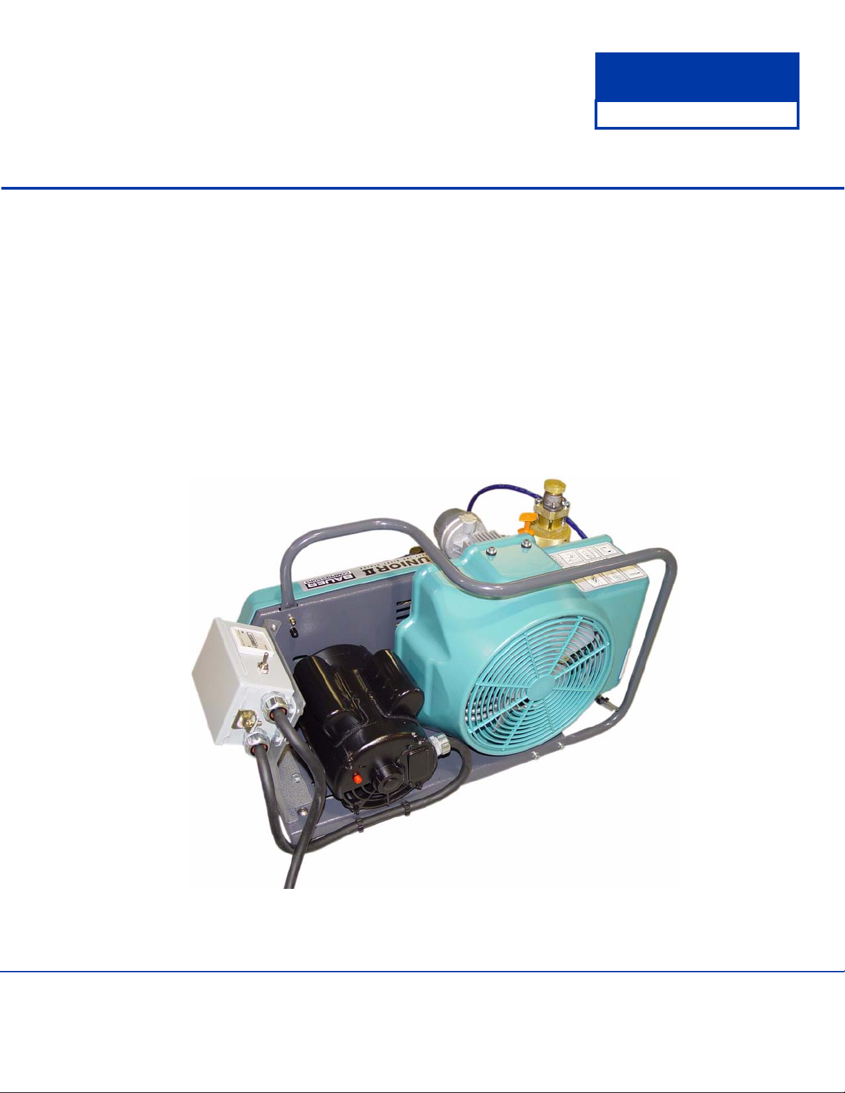
BAUER
COMPRESSORS
Instruction Manual and Replacement Parts List
Junior II
High Pressure Air Compressor Unit
Junior II WT
April 26, 2007 1st ed. Rev 0 Chg 3 MNL-0391
© 2007 Bauer Compressors, Inc.
BAUER Compressors, Inc. Phone: (757) 855-6006
1328 Azalea Garden Road Fax: (757) 855-6224
Norfolk, Virginia 23502-1944 www.bauercomp.com

BAUER
COMPRESSORS
This information is believed to be accurate by Bauer Compressors, Inc., as of it’s date of publication,
but Bauer offers NO WARRANTY regarding the accuracy, or continuing accuracy, of the information
set forth herein. Bauer shall not be liable for inaccuracies in, or consequences resulting from, your use
of this information. All information supplied is in connection with sales of Bauer’s products, and is thus
subject to Bauer’s standard terms and conditions of sale. Bauer reserves the right to change this information and has no obligation to update these materials. This information is © 2007 Bauer Compressors,
Inc., and Bauer reserves to itself all rights to this publication. Bauer’s customers have no right to reproduce, rewrite, modify, license or permit anyone else’s use of this information, without the express written permission of Bauer Compressors, Inc.
^ WARNING ^
This Instruction Manual and Replacement Parts List contains safety information and instructions for the
Junior II WT High Pressure Air Compressor Unit.
You must read, understand and follow all safety precautions and instructions.
Junior II WT
EDITIONS, REVISIONS AND CHANGES
• An Edition is the original or a complete rewriting of the entire Manual.
• A Revision occurs whenever a complete Section or Appendix is rewritten or added.
• A Change occurs when individual pages, drawings or tables are changed.
1st Edition
Rev Chg Date Notes Auth
0 0 02/28/2005 JD
0 1 9/9/2005 Changed Intermediate Separator to P/N 081800 JD
0 2 07/11/2006 Changes to Fig 3-14 JD
0 3 04/26/2007 Updated compressor block to Parts List TJ-4/7 from BKM JD
Page i 1st ed. Rev 0 Chg 3

MNL-0391
BAUER
COMPRESSORS
TABLE OF CONTENTS
CHAPTER 1:- - - - - - - - - - - - - - - - - - - - - INTRODUCTION
1.1 HOW TO USE THIS MANUAL.........................................................................................................................................1
1.1.1 Manual Safety Notices................................................... ....................................................................................................1
1.2 HOW TO USE THE REPLACEMENT PARTS LIST....................................................................................................2
1.3 HOW TO USE THE APPENDIX.......................................................................................................................................3
1.4 DESIGN................................................................................................................................................................................4
1.5 AIR FLOW DIAGRAM......................................................................................................................................................5
1.5.1 Junior II WT.......................................................................................................................................................................6
1.5.2 Compressor Block Technical Specifications......................................................................................................................6
1.5.3 Compressor Drive Technical Specifications......................................................................................................................6
CHAPTER 2:- - - - - - - - - - - - - - - - - - - - - - - OPERATION
2.1 PREPARATION FOR OPERATION................................................................................................................................7
2.2 STARTING THE UNIT......................................................................................................................................................7
2.3 FILLING PROCEDURE.................................................................................................................................................... 7
2.3.1 General Procedures ..........................................................................................................................................................8
2.3.2 Bottle Filling Procedures....................................................................................................................................................8
2.3.3 Connecting to the Air Storage Bottle................................................................................... ... ...........................................9
2.3.4 Filling the Bottle.................................................................................................................................................................9
2.3.5 Removing the Bottle...........................................................................................................................................................9
2.4 SHUT-DOWN PROCEDURES..........................................................................................................................................9
CHAPTER 3:- - - - - - - - - - - - - - - - JUNIOR II COMPRESSOR
3.1 LUBRICATION.................................................................................................................................................................10
3.1.1 Oil Level Check ........................................................................ .......................................................................................10
3.1.2 Type of Oil ....................................................................................................................................................................10
3.1.3 Oil Changes......................................................... .............................................................................................................11
3.1.3.1 Oil Change Procedures............................................... ..................................................................................................11
3.2 INTAKE FILTER..............................................................................................................................................................11
3.2.1 Description.......................................................................................................................................................................11
3.2.2 Maintenance.....................................................................................................................................................................11
3.2.3 Telescope Intake Tube .....................................................................................................................................................12
3.2.4 Intermediate Separator .....................................................................................................................................................12
3.2.5 Maintenance.....................................................................................................................................................................13
3.3 COMPRESSOR VALVES ................................................................................................................................................13
3.3.1 Description.......................................................................................................................................................................13
3.3.2 Initial Operational Check .................................................... ............................................................................................13
3.3.3 Changing the Valves ............................. ...........................................................................................................................13
3.3.4 Changing the 1st Stage Valves.........................................................................................................................................14
3.3.5 Changing the 2nd Stage Valves .......................................................................................................................................15
3.3.6 Changing the 3rd Stage Valves........................................................................................................................................16
3.4 REPAIR AND TROUBLESHOOTING...........................................................................................................................17
3.4.1 General Repair Instructions..............................................................................................................................................17
3.4.2 Troubleshooting Tables ...................................................................................................................................................18
April 26, 2007 Page ii

BAUER
COMPRESSORS
3.4.2.1 Electric Motor...............................................................................................................................................................18
3.4.2.2 Gasoline Engine............................................................................................................................................................18
3.4.2.3 Compressor Block.........................................................................................................................................................18
3.5 REPLACEMENT PARTS LIST ......................................................................................................................................20
Junior II WT
CHAPTER 4:- - - - - - - - - - - - - - - - - - - JRII MAINTENANCE
4.1 MAINTENANCE RECORD.............................................................................................................................................33
4.2 MAINTENANCE SCHEDULE........................................................................................................................................33
4.2.1 After the First 25 Operating Hours................................................. .................................... ..............................................33
4.2.2 Every 125 Operating Hours..............................................................................................................................................34
4.2.3 Every 2000 Operating Hours or Biennially......................................................................................................................34
4.2.4 Annually or As Required..................................................................................................................................................35
4.2.5 After Repair Work............................................................................................................................................................36
4.2.6 After Storage and Preservation.........................................................................................................................................38
CHAPTER 5:- - - - - - - - - - - - - - - - -PURIFICATION SYSTEM
5.1 GENERAL..........................................................................................................................................................................39
5.1.1 General Purification System Procedures..........................................................................................................................39
5.1.2 Chamber Safety Bore .......................................................................................................................................................39
5.1.3 Manual Condensate Drainage................................................................. ..........................................................................40
5.1.4 Model, Serial Number and Part Number Identification ...................................................................................................40
5.1.4.1 Compressor Dataplate ...................................................................................................................................................40
5.1.4.2 Purification System Dataplate ......................................................................................................................................40
5.1.4.3 Cartridge Installation Dataplate....................................................................................................................................40
5.1.5 Industrial Purification System Configurations ................................................................................................................41
5.1.6 Cartridge Operating Life ..................................................................................................................................................41
5.1.6.1 Calculating the Maximum Cartridge Operating Hours.................................................................................................42
5.1.6.2 Calculating the Adjusted Cartridge Operating Hours...................................................................................................42
5.1.6.3 Purification Cartridge Operating Hours Form..............................................................................................................44
5.2 P0 PURIFICATION SYSTEM.........................................................................................................................................45
5.2.1 Description .......................................................................................................................................................................45
5.2.2 Maintenance .....................................................................................................................................................................46
5.2.2.1 Replacing the Cartridge ................................................................................................................................................46
5.2.2.2 Chamber Replacement Interval ...................................................................................................................................47
5.2.3 Replacement Parts List.....................................................................................................................................................49
CHAPTER 6:- - - - - - - - - - - - - - - - - - - - MISCELLANEOUS
6.1 SAFETY VALVES.............................................................................................................................................................51
6.1.1 Description .......................................................................................................................................................................51
6.1.2 Maintenance .....................................................................................................................................................................51
6.1.2.1 Checking Function........................................................................................................................................................51
6.1.2.2 Checking Blow Off Pressure ........................................................................................................................................51
6.2 PRESSURE GAUGE.........................................................................................................................................................51
6.2.1 Maintenance .....................................................................................................................................................................51
6.3 COMPRESSOR DRIVE SYSTEM..................................................................................................................................52
6.3.1 Description .......................................................................................................................................................................52
6.3.2 Checking the Drive Belt...................................................................................................................................................52
6.3.3 V-belt Tension Adjustment ..............................................................................................................................................52
6.3.4 Electric Maintenance........................................................................................................................................................52
Page iii 1st ed. Rev 0 Chg 3

MNL-0391
6.4 COOLING SYSTEM.........................................................................................................................................................53
6.4.1 General.............................................................................................................................................................................53
BAUER
COMPRESSORS
CHAPTER 7:- - - - - - - - - - - - - - - - - - - - - - - - APPENDIX
7.1 SAFETY..............................................................................................................................................................................54
7.1.1 General Safety Precautions ..............................................................................................................................................54
7.1.2 Safety Warning Labels.....................................................................................................................................................56
7.2 INSTALLATION...............................................................................................................................................................57
7.2.1 Corrosion Resistance........................................................................................................................................................57
7.2.2 Outdoor Location .............................................................................................................................................................57
7.2.3 Indoor Location................................................................................................................................................................57
7.2.3.1 Electrical Installation....................................................................................................................................................57
7.3 STORAGE AND PRESERVATION...............................................................................................................................58
7.3.1 Storage..............................................................................................................................................................................58
7.3.2 Preservation......................................................................................................................................................................59
7.3.2.1 Preparation for Preservation.........................................................................................................................................59
7.3.2.2 Preserving the Compressor...........................................................................................................................................59
7.3.2.3 Preserving the Motor or Engine................................................ ....................................................................................59
7.3.2.4 Preventive Maintenance During Storage......................................................................................................................59
7.3.2.5 Reactivating the Compressor Unit................................................................................................................................60
7.4 TABLES AND REFERENCE DATA ..............................................................................................................................61
7.4.1 Tightening Torque Values ............................................................................................................................................61
7.4.2 Pipe Connections (swivel nuts)......................................................................................... ...............................................61
April 26, 2007 Page iv

BAUER
COMPRESSORS
Junior II WT
LIST OF FIGURES
CHAPTER 1:- - - - - - - - - - - - - - - - - - - - - INTRODUCTION
Figure 1-1 Junior II WT ............................................................................................................................................................4
Figure 1-2 Internal Air Flow Diagram......................................................................................................................................5
CHAPTER 2:- - - - - - - - - - - - - - - - - - - - - - - OPERATION
Figure 2-1 Air Storage Bottle Valve Operating Sequence........................................................................................................8
CHAPTER 3:- - - - - - - - - - - - - - - - JUNIOR II COMPRESSOR
Figure 3-1 Oil Dipstick Markings .............................................................. .............................................................................10
Figure 3-2 Intake Filter............................................................................................................................................................11
Figure 3-3 Intermediate Separator...........................................................................................................................................12
Figure 3-4 Valve Function.......................................................................................................................................................13
Figure 3-5 1st Stage Plate Valve.............................................................................................................................................13
Figure 3-6 1st Stage Valve Head.............................................................................................................................................14
Figure 3-7 2nd Stage Valve Head ........................................ .................................... ...............................................................15
Figure 3-8 3rd Stage Valve Head...................................... ... ...................................................................................................16
Figure 3-9 Removing the 3rd Stage Valves ............................................................................................................................17
Figure 3-10 Crankcase, Driving Gear and Fanwheel................................ ..................................... ...........................................20
Figure 3-11 Pistons and Cylinders ............................................................................................................................................22
Figure 3-12 Valve Heads and Valves.......................................... ..............................................................................................24
Figure 3-13 Cooler .............................................................................................................. ......................................................26
Figure 3-14 Intake Filter and Intermediate Separator ...............................................................................................................28
Figure 3-15 Frame with Accessories.........................................................................................................................................30
Figure 3-16 Special Tools ............................................................................... ..........................................................................32
CHAPTER 4:- - - - - - - - - - - - - - - - - - - JRII MAINTENANCE
There are no Figures in this Chapter
CHAPTER 5:- - - - - - - - - - - - - - - - -PURIFICATION SYSTEM
Figure 5-1 Cartridge Safety Venting.......................................................................................................................................39
Figure 5-2 Purification System Dataplates (typical) ...............................................................................................................40
Figure 5-3 Correction Factor for Cartridge Operating Hours .................................................................................................43
Figure 5-4 Example Record of Adjusted Operating Hours.....................................................................................................43
Figure 5-5 P0 Purification Chamber........................................................................................................................................45
Figure 5-6 P0 Purification System Cross Section ...................................................................................................................46
Figure 5-7 P0 Purification System Parts List..........................................................................................................................49
CHAPTER 6:- - - - - - - - - - - - - - - - - - - - MISCELLANEOUS
Figure 6-1 Final Pressure Safety Valve...................................................................................................................................51
Figure 6-2 Gauges ............................................................................................ .......................................................................51
Figure 6-3 Checking V-belt Tension.......................................................................................................................................52
Figure 6-4 V-belt Pulley Alignment........................................................................................................................................52
CHAPTER 7:- - - - - - - - - - - - - - - - - - - - - - - - -APPENDIX
Figure 7-1 Incoming Power Wiring Label ..............................................................................................................................58
Page v 1st ed. Rev 0 Chg 3

MNL-0391
BAUER
COMPRESSORS
CHAPTER 1: INTRODUCTION
1.1 How To Use This Manual
This manual contains the operating and maintenance instructions for the Bauer Compressors, Inc. product(s) listed on the front cover.
All instructions in this manual should be observed and carried out as written to prevent damage or premature wear to the product or the equipment served by it.
If your unit is equipped with nonstandard accessories and/or options, supplemental information is normally included in other documentation; i.e. OEM Manuals or additional Bauer Manuals.
While every effort is made to ensure the accuracy of the information contained in this manual, Bauer
Compressors, Inc. will not, under any circumstances be held accountable for any inaccuracies or the
consequences thereof.
1.1.1 Manual Safety Notices
Important instructions concerning the endangerment of personnel, technical safety or operator safety
will be specially emphasized in this manual by placing the information in the following types of safety
notices.
^ DANGER ^
DANGER indicates an imminently hazardous situation which, if not avoided, will result in death or
serious injury. This is limited to the most extreme situations.
^ WARNING ^
WARNING indicates a potentially hazardous situation which, if not avoided, could result in death
or injury.
^ CAUTION ^
CAUTION indicates a potentially hazardous situation which, if not avoided, may result in minor or
moderate injury. It may also be used to alert against unsafe practices.
^ NOTE ^
NOTE advise of technical requirements that require particular attention by the operator or the
maintenance technician for proper maintenance and utilization of the equipment.
April 26, 2007 Page 1
BAUER
COMPRESSORS
1.2 How to Use the Replacement Parts List
• A lozenge ◊ in the Item Number column indicates the part number for a complete assembly.
• A dagger (†) in the Qty column with or without an ellipsis (…) in the Part Number column means the
part is illustrated for assembly purposes only and is not available for sale as an individual component.
This part can be obtained by ordering the complete assembly.
• AR in the Qty column means that the item is cut or manufactured to the size which the customer specifies.
• A dash (—) in the Item Number column indicates that there is more than one part number applicable
to the preceding Item Number.
• The letter(s) in the columns labeled Kit indicate the number of operating hours when the part is to be
replaced; a = replaced every 1,000 hours, b = replaced every 2,000 hours and c= replaced every 4,000
hours.
• NS in the Item Number column indicates the part is not illustrated but is available.
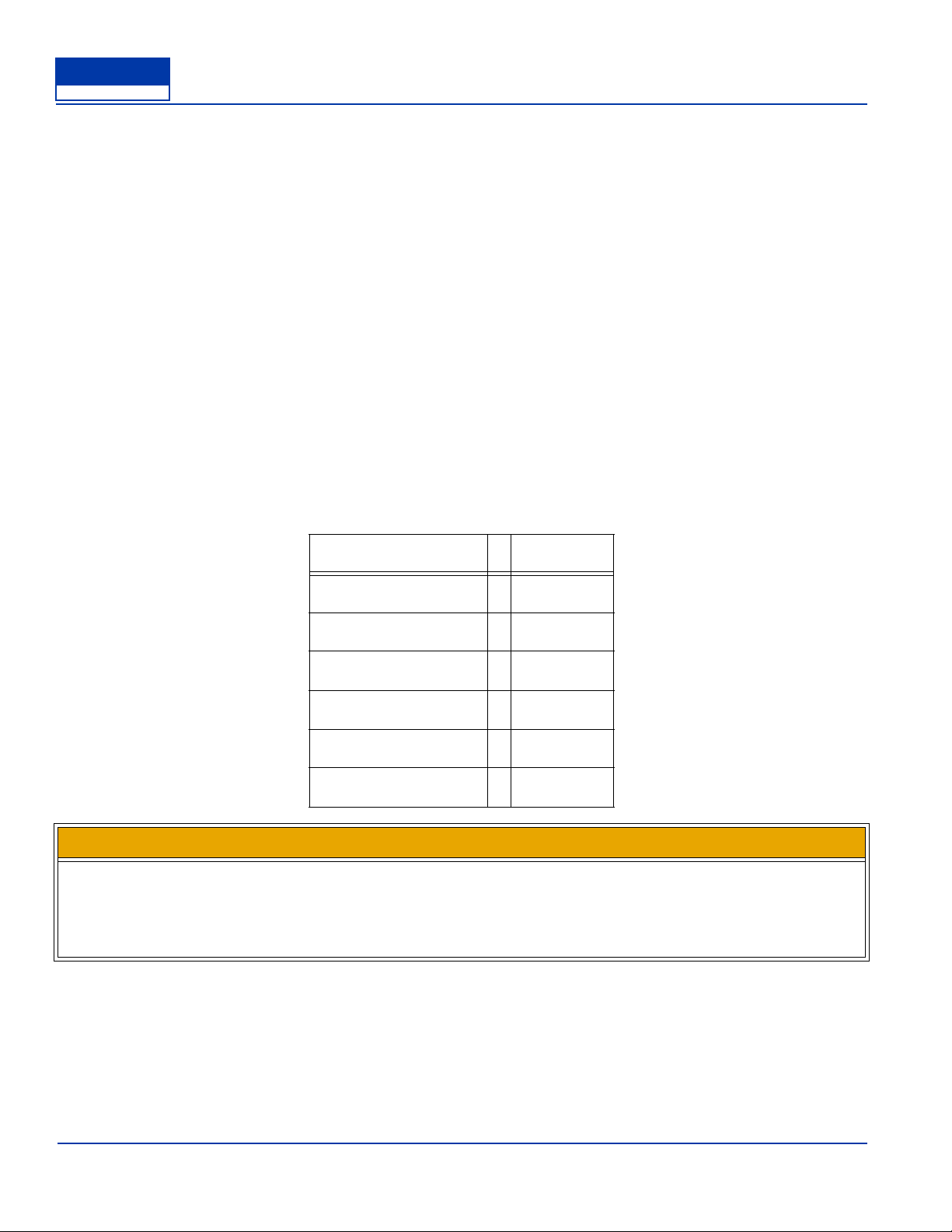
When placing an order for spare parts, please provide the following information to ensure delivery of
the correct parts. The model number, date of manufacture and serial number can be found of the compressor unit identification plate on the compressor unit’s frame.
JUNIOR II WT
Information Example
Model Number TCOM25
Serial Number 32165
Date of Manufacture 02/2005
Quantity required 2
Part Number N04860
Part Description Valve
^ WARNING ^
The use of repair parts other than those included in the Bauer Replacement Parts Lists may create unsafe
conditions over which Bauer has no control. Such unsafe conditions can lead to accidents that may be lifethreatening, cause substantial bodily injury, and/or result in damage to the equipment. Therefore, BAUER
Compressors, Inc. can bear no responsibility for equipment in which unapproved repair parts are installed.
Page 2 1st ed. Rev 0 Chg 3

MNL-0391
1.3 How to Use the Appendix
Information contained in the Appendix to this manual includes the following.
• The safety instructions applicable to this product. They must be read, understood and complied with
prior to operating the product.
• The instructions for installing this product. They must be read, understood and complied with prior to
operating the product.
• The instructions for long term storage (over 90 days) of this product.
BAUER
COMPRESSORS
April 26, 2007 Page 3
BAUER
1
2
3
4
5
6
7
8
9
10
COMPRESSORS
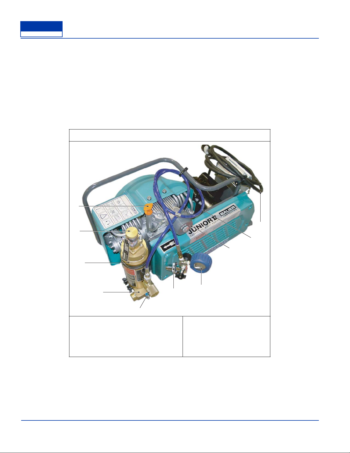
1.4 Design
The Junior II WT compressor units consists of the following major assemblies.
• Compressor Block
• Electric Motor Drive
• P0 Purification System
• Fill Hose Assembly
• Base Plate and Frame
Figure 1-1 Junior II WT
Junior II WT
1. Oil Dipstick
2. Final Pressure Valve
3. P0 Purification System
4. Pressure Maintaining Valve
5. CO and Moisture Indicator
Page 4 1st ed. Rev 0 Chg 3
6. Fill Adapter
7. Pressure Gauge
8. AIr Intake Filter
9. Fill Hose
10. Electric Cable and Plug
MNL-0391
BAUER
COMPRESSORS
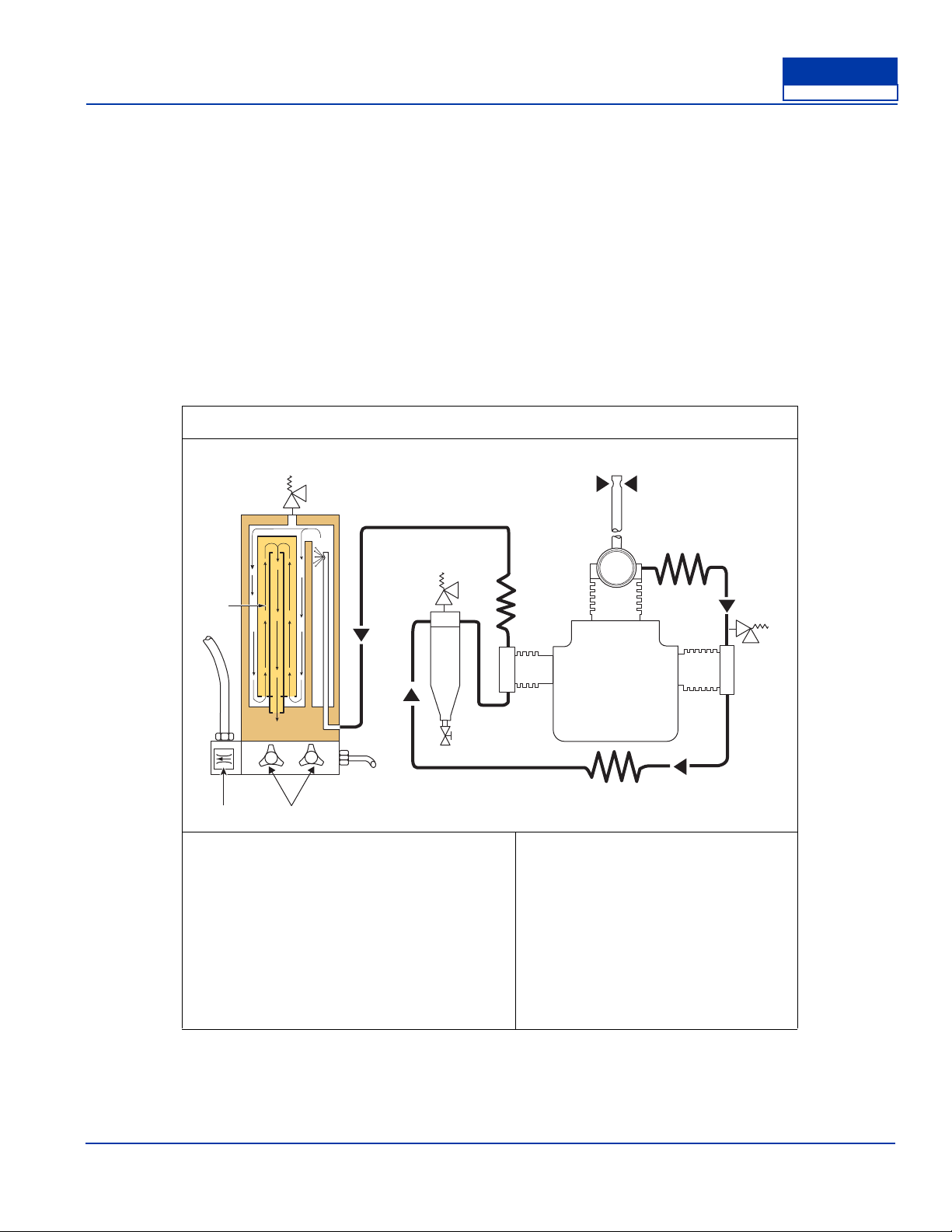
1.5 Air Flow Diagram
See Figure 1-4.
The air is drawn in through the Telescopic Tube (1) through the Intake Filter (2) and is compressed to
final pressure in the Cylinders (3, 4 and 5). It is recooled by the Intercoolers (6 and 7) and the Aftercooler (9). The pressure of the individual stages is controlled by Safety Valves (10 and 11). The compressed air is cleaned in the Intermediate Separator (8) and purified in the P0 Filter System (13). The
Intermediate Separator and P0 Filter System are drained by the Condensate Drain Valves (15). The
Pressure Maintaining Valve (16) provides a constant pressure within the P0 Filter System. The purified
compressed air then passes through the Fill Hose (17) and Fill Valve (18) to the bottles to be filled. Fill
pressure is indicated by the Final Pressure Gauge (19).The Final Safety Valve (12) is adjusted to blow
off at the pressure selected.
Figure 1-2 Internal Air Flow Diagram
12
13
11
14
17
16
15
8
15
1. Compressor Air Intake Extensions
2. Intake Filter
3. 1st Stage Cylinder
4. 2nd Stage Cylinder
5. 3rd Stage Cylinder
6. 1st/2nd Stage Intercooler
7. 2nd/3rd Stage Intercooler
8. Intermediate Separator
9. After Cooler
1
6
2
9
3
5
7
4
10. 1st Stage Safety Valve
11. 2nd Stage Safety Valve
12. Final Pressure Safety Valve
13. P0 Filter System
®
14. Triplex
Longlife Cartridge
15. Condensate Drain Valve
16. Pressure Maintaining Valve
17. Fill Hose
10
April 26, 2007 Page 5

BAUER
COMPRESSORS
1.5.1 Junior II WT
Medium Air
Intake Pressure Atmospheric
Delivery
Maximum Operating Pressure 5,000 psi (350 bar)
Final Safety Valve Pressure Setting As selected
Sound Pressure 80dB(A)
Sound (immersion) Power 100dB(A)
Weight Approximately 100 lbs (44-47 kg)
1.5.2 Compressor Block Technical Specifications
Number of stages 3
Number of cylinders 3
1st Stage Cylinder Bore 60mm
2nd Stage Cylinder Bore 28mm
3rd Stage Cylinder Bore 12mm
Intermediate Pressure 1st stage 94 psi (6.5 bar)
Intermediate Pressure 2nd stage 943 psi (65 bar)
Compressor Block Oil Capacity 12 fluid ounces (360 cc)
Maximum Ambient Temperature 41° - 113°F (5°-45° C)
Maximum Inclination of Compressor
1
2
Junior II WT
1.0 SCFM (100l/min.)
5°
1.5.3 Compressor Drive Technical Specifications
Drive Motor P/N MTR-0219
Operating Voltage 115 VAC, Single Phase, 60 Hz
Horsepower 1½HP
Speed 3600 RPM
Type ODP
1. Free air delivered at bottle filling from 0 to 5,000 psi (0-350 bar) ± 5%
2. This value is valid only if the compressor block oil in normal level position corresponds with the upper mark of the oil dipstick an d may not be exceeded.
Page 6 1st ed. Rev 0 Chg 3

MNL-0391
BAUER
COMPRESSORS
CHAPTER 2: OPERATION
2.1 Preparation for Operation
Prior to operating the unit for the first time, read this Instruction Manual carefully.
1. Make sure that all persons operating the compressor unit and associated equipment are familiar with
the function of all controls and indicators.
2. Thoroughly comply with the paragraphs titled Safety contained in the Appendix to this manual.
3. If the unit has been out of service for two years or more and uses synthetic compressor oil change
the compressor oil. If the unit uses petroleum based compressor oil change it after being out of service one year.
4. During the initial operation or prior to operation subsequent to repairs operate the unit for at least
five minutes with open outlet valve (unpressurized) to ensure proper lubrication of all parts before
pressure is built up.
5. Prior to each operation check the oil level according to Section 2 Lubrication and determine
whether maintenance is necessary in accordance with Section 13.
6. Every time the unit is started, check all systems for proper operation. If any malfunction is observed
stop the unit immediately and find the cause of the fault or call the service department.
2.2 Starting the Unit.
1. Close condensate drain valves and run the unit to the final pressure. Check final pressure safety
valve and pressure gauge.
2. As soon as the final pressure safety valve blows off, open the condensate valve and drain conden-
sate. The unit is now ready for filling operations.
2.3 Filling Procedure
^ WARNING ^
Ensure the intake air is free from noxious gas, exhaust fumes and solvent vapors.
^ WARNING ^
Never open fill valves or shut off valves when under pressure and the hose is not connected as discharging
high pressure compressed air can cause serious accidents.
^ WARNING ^
Fill hoses must be in satisfactory condition and the threads must be undamaged. Pay particular attention to
the interface from hose fitting to hose. If the rubber is scored, the hose must be discarded, otherwise water
can corrode the wire gauze causing a hose failure.
April 26, 2007 Page 7
BAUER
COMPRESSORS
2.3.1 General Procedures
1. The fill valve connection is of the manual type permitting connection to the air tank without tools.
An O-ring is provided for sealing purposes.
2. Compressed air tank fill valves for pressure in excess of 2900 psi (200 bar) are standardized and
connectors for 2900 psi (200 bar) and 4400 psi (300 bar) are different and can not be mixed up.
3. To ensure safe air tank removal after filling, the fill valve has an integral venting bore. Therefore
always close the tank valve before closing the fill valve.
4. During the fill procedure the bottles will warm up due to recompression.
5. After filling, remove and allow the bottle to cool down. When it is cool the bottle may be reconnected and topped up to its maximum filling pressure.
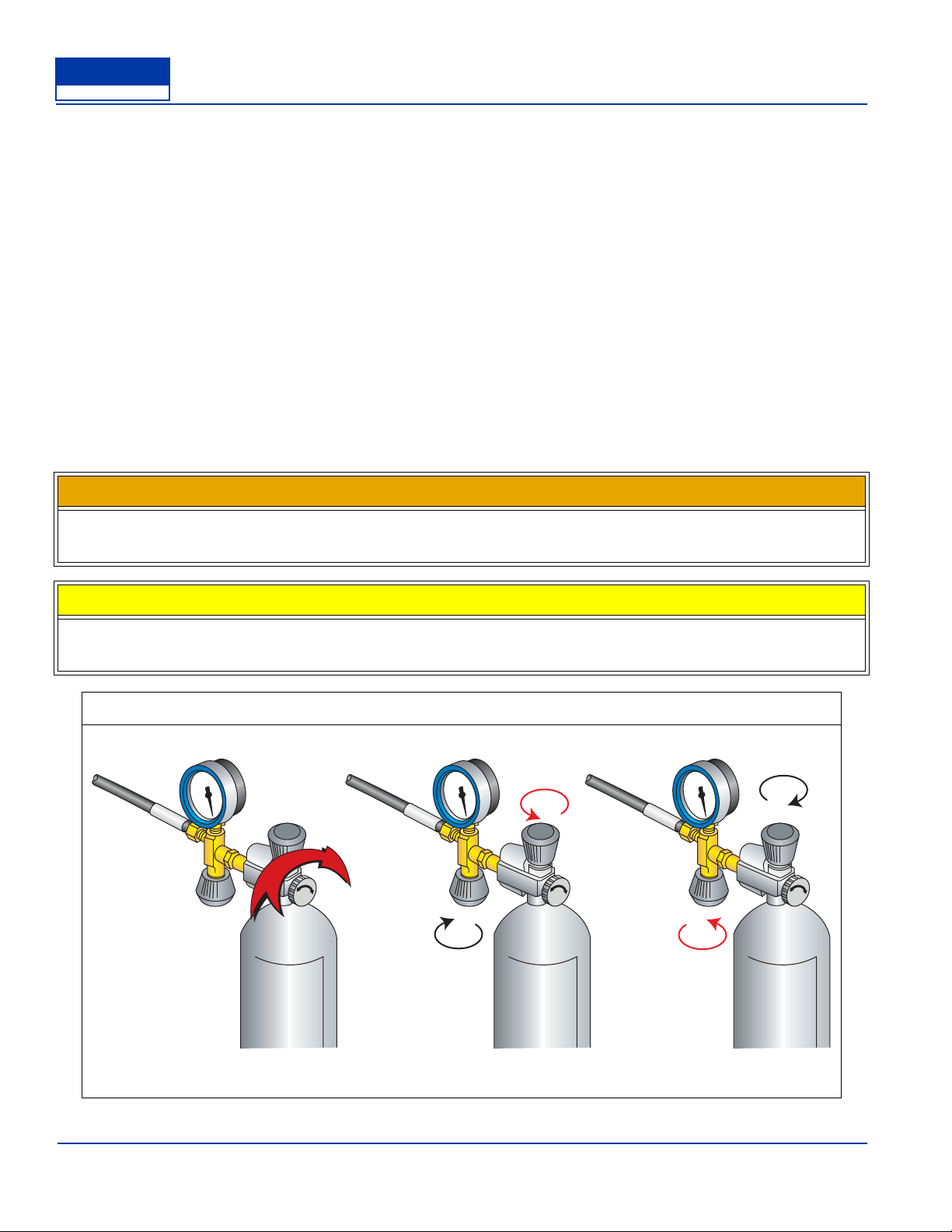
2.3.2 Bottle Filling Procedures
See Figure 2-1
^ WARNING ^
Never open the fill valve unless the bottle is connected to the fill hose. Whipping of an unrestrained hose
caused by high pressure air discharge can cause serious injury!
Junior II WT
^ CAUTION ^
The filling procedure should not be interrupted for more than 10 minutes to avoid increased CO2 levels in
the air filling the bottle.
Figure 2-1 Air Storage Bottle Valve Operating Sequence
1.
2.
1.
2.
Attaching the Fill Yoke
Page 8 1st ed. Rev 0 Chg 3
Opening Sequence
Closing Sequence

MNL-0391
2.3.3 Connecting to the Air Storage Bottle
1. Ensure both the fill valve and bottle valve are closed
2. Connect the air bottle to the compressor fill hose utilizing the fill yoke.
2.3.4 Filling the Bottle
1. First open fill valve. (1)
2. Open bottle valve. (2)
3. Bottle will begin filling.
4. During the filling process, monitor bottle pressure on fill valve gauge and drain condensate at the
compressor.
2.3.5 Removing the Bottle
1. First close the bottle valve. (1)
2. Close the fill valve. (2)
COMPRESSORS
BAUER
3. Remove fill yoke and store compressed air bottle.
2.4 Shut-Down Procedures
1. On all units first close the fill valve.
2. Turn off electrical power with the appropriate switch
3. Vent unit to approximately 1,150 psi (80 bar).
4. Decompress with drain valves to remove all moisture in the filter and the oil and water separator.
5. Close all drain valves again.
6. Check the oil level in the compressor and top up, if necessary.
7. Also check operating hours to see if the compressor needs servicing in accordance with the mainte-
nance schedule.
April 26, 2007 Page 9

BAUER
COMPRESSORS
CHAPTER 3: JUNIOR II COMPRESSOR
3.1 Lubrication
3.1.1 Oil Level Check
Check the oil level prior to putting compressor into operation each day
1. Remove dipstick and wipe dry.
2. Reinsert the dipstick ensuring that it is completely seated.
3. Withdraw the dipstick again and note the oil level.
The level should be between the minimum and maximum marks on the dipstick.See Figure 3-1.
Figure 3-1 Oil Dipstick Markings
Junior II WT
Max.
Min.
^ CAUTION ^
The oil level must not go down below the minimum mark but also must not exceed the maximum
mark as this will cause excessive lubrication of the compressor and result in the valves carbonizing.
3.1.2 Type of Oil
^ NOTE ^
The part number for the oil delivered in all Junior II compressor units is BAUER part number:
OIL-0024
Due to the thermal load on the compressor, only high quality oil should be used. It is recommended that
you restrict oil to BAUER P/N OIL-0024 which has a proven record of success and is specified for this
compressor.
Page 10 1st ed. Rev 0 Chg 3
MNL-0391
3.1.3 Oil Changes
The oil must be changed every 2,000 operating hours or every two years whichever is reached first.
3.1.3.1 Oil Change Procedures
1. Run the compressor until it reaches normal operating temperature.
2. Remove the oil dipstick from oil filler tube.
3. While the oil is still warm, remove oil drain plug and drain oil into an appropriate container.
4. After oil has completely drained, reinstall oil drain plug and tighten.
5. Refill with 12 Fluid Ounces (360 cc) of oil, through the oil filler tube.
6. Check oil level using the oil dipstick.
7. Oil level is correct if it is at the upper mark.See Figure 3-1
3.2 Intake Filter
3.2.1 Description
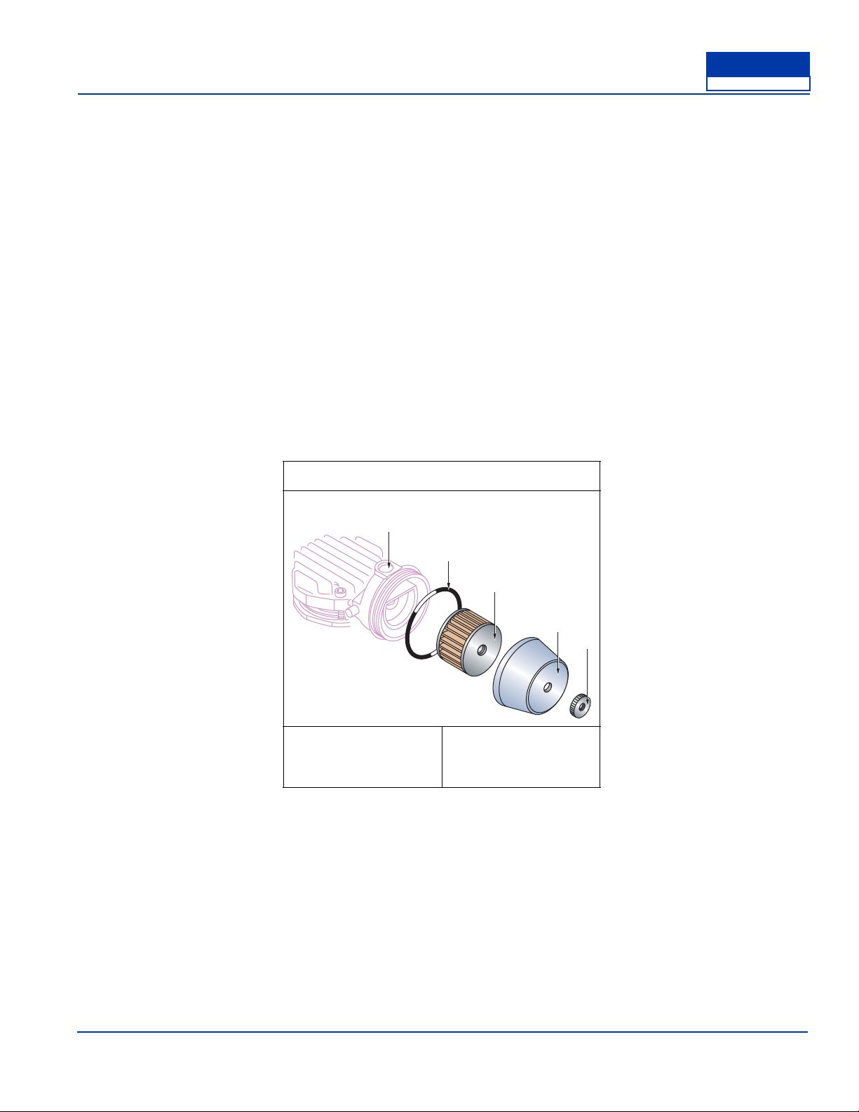
A dry micronic filter is used to filter the intake air. See Figure 3-2
BAUER
COMPRESSORS
Figure 3-2 Intake Filter
5
4
3
2
1
1. Knurled Nut
2. Plastic Cap
4. O-ring
5. Intake Opening
3. Filter Cartridge
3.2.2 Maintenance
The filter cartridge must be changed at regular intervals according to the maintenance schedule.
1. Remove knurled nut (1) and take off plastic cap (2).
2. Permanently mark filter cartridge (3) at the twelve o’clock position.
3. After cartridge has been cleaned three times (3 marks) it is dirty on all sides and must be replaced
with a new cartridge.
4. Remove filter cartridge and clean with a brush or by blowing air from the inside to the outside.
5. Clean the inside of the filter housing with a damp cloth. Take care to prevent dust from entering the
opening into the compressor.
April 26, 2007 Page 11
BAUER
COMPRESSORS
Junior II WT
6. Reinsert filter cartridge, turning it 90° so the mark made in step 2. is at the 3 o’clock position.
7. Inspect O-ring (4) and replace if damaged.
8. Replace plastic cap and tighten knurled nut
3.2.3 Telescope Intake Tube
See Figure 3-2. The telescopic intake tube is inserted in the intake opening (5). This is necessary to
ensure clean intake air on gasoline engine driven compressor units. It’s use is also recommended with
electric motor driven compressor units.
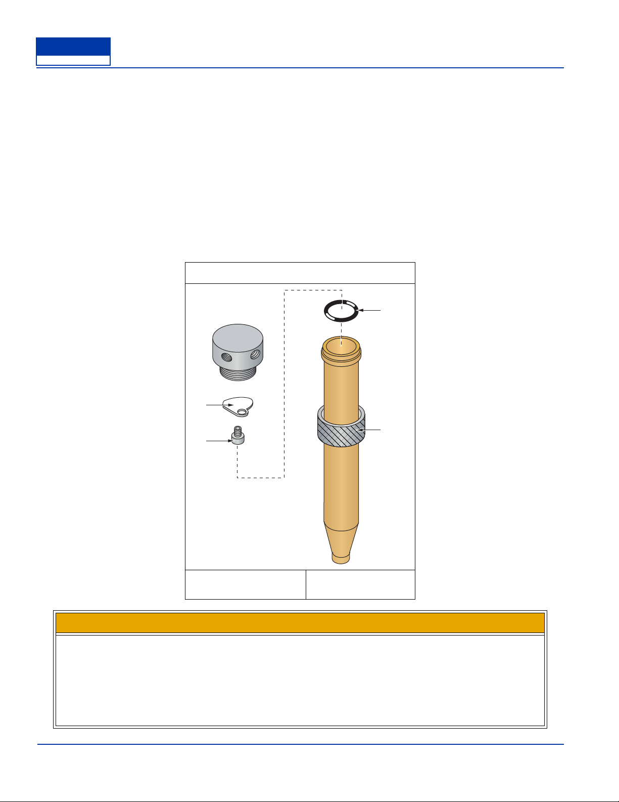
3.2.4 Intermediate Separator
An intermediate separator is mounted on the compressor block. This separator is designed to remove oil
and water which accumulates due to the cooling of the medium after the compression process. Separation
is achieved by means of centrifugal action provided by a vortex plate (1)
Figure 3-3 Intermediate Separator
3
1
4
2
1. Vortex Plate
2. Hollow Screw
3. O-ring
4. Knurled Nut
^ WARNING ^
The rapid depressurizing and repressurizing of the intermediate separator during condensate draining subjects it to metallurgical stresses. To prevent catastrophic failure with the possibility of damage, injury or death the intermediate separator must be replaced after 85,000 load cycles. A load
cycle equals one depressurization- repressurization. The Bauer recommended frequency of condensate draining is every fifteen minutes and is a balance between maximizing the life of the oil
and water separator chamber and maintaining the quality of the delivered air.
Page 12 1st ed. Rev 0 Chg 3

MNL-0391
Intake Pressure
BAUER
COMPRESSORS
3.2.5 Maintenance
The Intermediate Separator P/N 081798 requires no maintenance.
3.3 Compressor Valves
3.3.1 Description
The valve heads of the individual stages form the top part of the cylinders. The intake and pressure valves
are fitted inside the valve heads. (Note that the valves are operated by air flow. (See Figure 3-4). On the
suction stroke, the intake valve is opened and air flows into the cylinder. At the start of the compression
stroke the intake valve closes. the end of the compression stroke the compressed air forces the pressure
valve open.
The 1st Stage combines the intake and pressure valves in a plate valve. (See Figure 3-5).
Figure 3-4 Valve Function Figure 3-5 1st Stage Plate Valve
Intake
Side
S
From
Intake
Filter
To
2nd
Stage
Discharge
Side
N4860-F98
3.3.2 Initial Operational Check
After maintenance work on the valves, the valves should be checked for proper operation. Note that the
intake line to the valve heads is warm and the outlet piping should be hot. This indicates the valves are
operating correctly.
3.3.3 Changing the Valves
• Always replace the valves as a complete set.
• Observe the correct sequence when reassembling.
• Check individual components for excessive wear . If the valve seat and valve dis ks are dented, replace
the valves.
• Valve head screws must be tightened with a torque wrench.
• Check the valve space in the valve head for dirt and clean if necessary.
April 26, 2007 Page 13
BAUER
COMPRESSORS
Junior II WT
• Thirty minutes after restarting the compressor unit, stop the unit, let it cool to ambient temperature
and retighten the valve studs and cap nuts. Otherwise valves could work loose due to the setting of the
gaskets.
• After finishing all maintenance work on the valves, turn the compressor by hand using the flywheel
and check that all items have been correctly installed.
• Remove and check the valves every 1,000 operating hours.
• Replace the valves every 2,000 operating hours to avoid fatigue failure
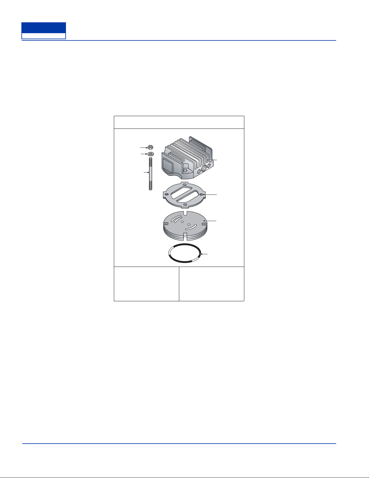
Figure 3-6 1st Stage Valve Head
7
6
5
1
2
3
4
1. Valve Head
2. Gasket
3. Plate Valve
4. O-ring
5. Valve Head
Screw
6. Washer
7. Hex Nut
3.3.4 Changing the 1st Stage Valves
• Loosen the two cap nuts from tube connectors and remove after-cooler.
• Remove four valve head screws (5) from valve head (1). Remove valve head.
• Remove gasket (2) and plate valve (3).
• When reinstalling the plate valve, check that the mark “S” is facing upwards and towards the inlet
filter side. The cross bar of the gasket (2) provides a seal between the inlet and pressure opening of
the plate valve.
Page 14 1st ed. Rev 0 Chg 3
Loading...