


Operator’s Manual
High Pressure Breathing Air Compressors

Operator’s Manual
INTRODUCTION
This manual contains general information and instructions to operate and maintain high pressure breathing air compressor units.
Before taking the compressor into operation it is essential to study the instruction manual of that compressor.
All instructions should be observed and carried out in the order laid down to prevent damage and premature wear to the equipment and the units served by it.
While every effort is made to ensure the accuracy of the particulars contained in this manual, the manufacturing company will not, under any circumstances, be held liable for any inaccuracies or the consequences thereof.
WARNING
The breathing air produced with this high pressure compressor is subject to strict quality standards. Ignoring the operating and maintenance instructions can lead to severe injury or in serious cases even death.
We reserve the right to make changes to the technology of our compressors as well as to this accompanying documentation in accordance to technical progress.
Edition January 2005
© 2005 BAUER Kompressoren GmbH, Munich
All rights reserved.
i

|
|
Operator’s Manual |
TABLE OF CONTENTS |
|
|
1. |
GENERAL . . . . . . . . . . . . . . . . . . . . . . . . . . . . . . . . . . . . . . . . . . . . . . . . . . . . . . . . . . . . . . . . . . . . . . . . . . . |
. . . . . . . . 1 |
1.1. |
PURPOSE AND SHORT DESCRIPTION . . . . . . . . . . . . . . . . . . . . . . . . . . . . . . . . . . . . . . . . . . . . . . . . . |
. . . . . . . . 1 |
1.2. |
THEORETICAL PRINCIPLES . . . . . . . . . . . . . . . . . . . . . . . . . . . . . . . . . . . . . . . . . . . . . . . . . . . . . . . . . . . |
. . . . . . . . 2 |
1.3. |
DESIGN AND MODE OF OPERATION . . . . . . . . . . . . . . . . . . . . . . . . . . . . . . . . . . . . . . . . . . . . . . . . . . . |
. . . . . . . . 4 |
2. |
SAFETY REGULATIONS . . . . . . . . . . . . . . . . . . . . . . . . . . . . . . . . . . . . . . . . . . . . . . . . . . . . . . . . . . . . . . |
. . . . . . . . 8 |
2.1. |
GENERAL . . . . . . . . . . . . . . . . . . . . . . . . . . . . . . . . . . . . . . . . . . . . . . . . . . . . . . . . . . . . . . . . . . . . . . . . . . . |
. . . . . . . . 8 |
2.2. |
NOTES AND WARNING SIGNS . . . . . . . . . . . . . . . . . . . . . . . . . . . . . . . . . . . . . . . . . . . . . . . . . . . . . . . . . |
. . . . . . . . 9 |
2.3. |
IDENTIFYING THE SAFETY NOTICES . . . . . . . . . . . . . . . . . . . . . . . . . . . . . . . . . . . . . . . . . . . . . . . . . . . |
. . . . . . . . 9 |
2.4. |
FUNDAMENTAL SAFETY NOTICES . . . . . . . . . . . . . . . . . . . . . . . . . . . . . . . . . . . . . . . . . . . . . . . . . . . . . |
. . . . . . . . 9 |
2.5. |
SAFETY REGULATIONS (EC; partly Germany, only) . . . . . . . . . . . . . . . . . . . . . . . . . . . . . . . . . . . . . . . . |
. . . . . . . . 12 |
3. |
INSTALLATION, OPERATION . . . . . . . . . . . . . . . . . . . . . . . . . . . . . . . . . . . . . . . . . . . . . . . . . . . . . . . . . . |
. . . . . . . . 13 |
3.1. |
INSTALLATION OF THE COMPRESSOR UNIT . . . . . . . . . . . . . . . . . . . . . . . . . . . . . . . . . . . . . . . . . . . . |
. . . . . . . . 13 |
3.2. |
COMPRESSOR ROOM CONDITIONS: . . . . . . . . . . . . . . . . . . . . . . . . . . . . . . . . . . . . . . . . . . . . . . . . . . . |
. . . . . . . . 14 |
3.3. |
NATURAL VENTILATION . . . . . . . . . . . . . . . . . . . . . . . . . . . . . . . . . . . . . . . . . . . . . . . . . . . . . . . . . . . . . . . |
. . . . . . . . 16 |
3.4. |
ARTIFICIAL VENTILATION . . . . . . . . . . . . . . . . . . . . . . . . . . . . . . . . . . . . . . . . . . . . . . . . . . . . . . . . . . . . . |
. . . . . . . . 19 |
3.5. |
ELECTRICAL INSTALLATION . . . . . . . . . . . . . . . . . . . . . . . . . . . . . . . . . . . . . . . . . . . . . . . . . . . . . . . . . . . |
. . . . . . . . 22 |
3.6. |
TAKING INTO OPERATION . . . . . . . . . . . . . . . . . . . . . . . . . . . . . . . . . . . . . . . . . . . . . . . . . . . . . . . . . . . . . |
. . . . . . . . 23 |
3.7. |
FILLING PROCEDURE . . . . . . . . . . . . . . . . . . . . . . . . . . . . . . . . . . . . . . . . . . . . . . . . . . . . . . . . . . . . . . . . |
. . . . . . . . 25 |
3.8. |
SHUT--DOWN PROCEDURE . . . . . . . . . . . . . . . . . . . . . . . . . . . . . . . . . . . . . . . . . . . . . . . . . . . . . . . . . . . |
. . . . . . . . 28 |
4. |
MAINTENANCE . . . . . . . . . . . . . . . . . . . . . . . . . . . . . . . . . . . . . . . . . . . . . . . . . . . . . . . . . . . . . . . . . . . . . . |
. . . . . . . . 29 |
4.1. |
MAINTENANCE RECORD . . . . . . . . . . . . . . . . . . . . . . . . . . . . . . . . . . . . . . . . . . . . . . . . . . . . . . . . . . . . . . |
. . . . . . . . 29 |
4.2. |
MAINTENANCE INTERVALS . . . . . . . . . . . . . . . . . . . . . . . . . . . . . . . . . . . . . . . . . . . . . . . . . . . . . . . . . . . |
. . . . . . . . 29 |
5. |
MAINTENANCE SCHEDULE . . . . . . . . . . . . . . . . . . . . . . . . . . . . . . . . . . . . . . . . . . . . . . . . . . . . . . . . . . . |
. . . . . . . . 30 |
5.1. |
MAINTENANCE INTERVALS . . . . . . . . . . . . . . . . . . . . . . . . . . . . . . . . . . . . . . . . . . . . . . . . . . . . . . . . . . . |
. . . . . . . . 30 |
5.2. |
MAINTENANCE RECORD . . . . . . . . . . . . . . . . . . . . . . . . . . . . . . . . . . . . . . . . . . . . . . . . . . . . . . . . . . . . . . |
. . . . . . . . 31 |
6. |
STORAGE, PRESERVATION . . . . . . . . . . . . . . . . . . . . . . . . . . . . . . . . . . . . . . . . . . . . . . . . . . . . . . . . . . . |
. . . . . . . . 32 |
6.1. |
GENERAL . . . . . . . . . . . . . . . . . . . . . . . . . . . . . . . . . . . . . . . . . . . . . . . . . . . . . . . . . . . . . . . . . . . . . . . . . . . |
. . . . . . . . 32 |
6.2. |
PREPARATION . . . . . . . . . . . . . . . . . . . . . . . . . . . . . . . . . . . . . . . . . . . . . . . . . . . . . . . . . . . . . . . . . . . . . . . |
. . . . . . . . 32 |
6.3. |
PRESERVING THE COMPRESSOR . . . . . . . . . . . . . . . . . . . . . . . . . . . . . . . . . . . . . . . . . . . . . . . . . . . . . |
. . . . . . . . 32 |
6.4. |
PRESERVING THE MOTOR/ENGINE . . . . . . . . . . . . . . . . . . . . . . . . . . . . . . . . . . . . . . . . . . . . . . . . . . . . |
. . . . . . . . 32 |
6.5. |
PREVENTIVE MAINTENANCE DURING STORAGE . . . . . . . . . . . . . . . . . . . . . . . . . . . . . . . . . . . . . . . |
. . . . . . . . 32 |
6.6. |
REACTIVATING THE COMPRESSOR UNIT . . . . . . . . . . . . . . . . . . . . . . . . . . . . . . . . . . . . . . . . . . . . . . |
. . . . . . . . 33 |
7. |
REPAIR INSTRUCTIONS . . . . . . . . . . . . . . . . . . . . . . . . . . . . . . . . . . . . . . . . . . . . . . . . . . . . . . . . . . . . . . |
. . . . . . . . 34 |
7.1. |
GENERAL . . . . . . . . . . . . . . . . . . . . . . . . . . . . . . . . . . . . . . . . . . . . . . . . . . . . . . . . . . . . . . . . . . . . . . . . . . . |
. . . . . . . . 34 |
8. |
TROUBLE-SHOOTING . . . . . . . . . . . . . . . . . . . . . . . . . . . . . . . . . . . . . . . . . . . . . . . . . . . . . . . . . . . . . . . . |
. . . . . . . . 35 |
9. |
FILTER SYSTEM P21 . . . . . . . . . . . . . . . . . . . . . . . . . . . . . . . . . . . . . . . . . . . . . . . . . . . . . . . . . . . . . . . . . . |
. . . . . . . . 37 |
9.1. |
DESCRIPTION . . . . . . . . . . . . . . . . . . . . . . . . . . . . . . . . . . . . . . . . . . . . . . . . . . . . . . . . . . . . . . . . . . . . . . . |
. . . . . . . . 37 |
9.2. |
CARTRIDGE SAFETY BORE . . . . . . . . . . . . . . . . . . . . . . . . . . . . . . . . . . . . . . . . . . . . . . . . . . . . . . . . . . . |
. . . . . . . . 38 |
9.3. |
LIFETIME . . . . . . . . . . . . . . . . . . . . . . . . . . . . . . . . . . . . . . . . . . . . . . . . . . . . . . . . . . . . . . . . . . . . . . . . . . . . |
. . . . . . . . 38 |
9.4. |
GENERAL INSTRUCTIONS FOR FILTER MAINTENANCE . . . . . . . . . . . . . . . . . . . . . . . . . . . . . . . . . . |
. . . . . . . . 39 |
9.5. |
CONDENSATE DRAINAGE . . . . . . . . . . . . . . . . . . . . . . . . . . . . . . . . . . . . . . . . . . . . . . . . . . . . . . . . . . . . . |
. . . . . . . . 39 |
ii

Operator’s Manual
9.6. |
FILTER CARTRIDGES . . . . . . . . . . . . . . . . . . . . . . . . . . . . . . . . . . . . . . . . . . . . . . . . . . . . . . . . . . . . . . . . . . . . . . . . . |
39 |
9.7. |
FILTER SERVICE LIFETIME . . . . . . . . . . . . . . . . . . . . . . . . . . . . . . . . . . . . . . . . . . . . . . . . . . . . . . . . . . . . . . . . . . . . |
39 |
9.8. |
CARTRIDGE CHANGE . . . . . . . . . . . . . . . . . . . . . . . . . . . . . . . . . . . . . . . . . . . . . . . . . . . . . . . . . . . . . . . . . . . . . . . . |
40 |
iii

|
|
Operator’s Manual |
TABLE OF CONTENTS |
|
|
9.9. |
FILLING VALVE MAINTENANCE . . . . . . . . . . . . . . . . . . . . . . . . . . . . . . . . . . . . . . . . . . . . . . . . . . . . . . . . |
. . . . . . . . 40 |
9.10. |
REPLACEMENT INTERVALS . . . . . . . . . . . . . . . . . . . . . . . . . . . . . . . . . . . . . . . . . . . . . . . . . . . . . . . . . . . |
. . . . . . . . 41 |
9.11. |
CONDENSATE DRAINAGE . . . . . . . . . . . . . . . . . . . . . . . . . . . . . . . . . . . . . . . . . . . . . . . . . . . . . . . . . . . . . |
. . . . . . . . 41 |
9.12. |
CARTRIDGE CHANGE . . . . . . . . . . . . . . . . . . . . . . . . . . . . . . . . . . . . . . . . . . . . . . . . . . . . . . . . . . . . . . . . |
. . . . . . . . 41 |
10. |
FILTER SYSTEM P41 AND P61 . . . . . . . . . . . . . . . . . . . . . . . . . . . . . . . . . . . . . . . . . . . . . . . . . . . . . . . . . |
. . . . . . . . 42 |
10.1. |
APPLICATION AND SUMMARY DESCRIPTION . . . . . . . . . . . . . . . . . . . . . . . . . . . . . . . . . . . . . . . . . . . |
. . . . . . . . 42 |
10.2. |
FUNCTION . . . . . . . . . . . . . . . . . . . . . . . . . . . . . . . . . . . . . . . . . . . . . . . . . . . . . . . . . . . . . . . . . . . . . . . . . . . |
. . . . . . . . 43 |
10.3. |
FILTER MAINTENANCE . . . . . . . . . . . . . . . . . . . . . . . . . . . . . . . . . . . . . . . . . . . . . . . . . . . . . . . . . . . . . . . |
. . . . . . . . 48 |
10.4. |
TECHNICAL DATA . . . . . . . . . . . . . . . . . . . . . . . . . . . . . . . . . . . . . . . . . . . . . . . . . . . . . . . . . . . . . . . . . . . . |
. . . . . . . . 51 |
11. |
LUBRICATING OIL LIST . . . . . . . . . . . . . . . . . . . . . . . . . . . . . . . . . . . . . . . . . . . . . . . . . . . . . . . . . . . . . . . |
. . . . . . . . 52 |
11.1. |
GENERAL . . . . . . . . . . . . . . . . . . . . . . . . . . . . . . . . . . . . . . . . . . . . . . . . . . . . . . . . . . . . . . . . . . . . . . . . . . . |
. . . . . . . . 52 |
11.2. |
TYPE OF OIL . . . . . . . . . . . . . . . . . . . . . . . . . . . . . . . . . . . . . . . . . . . . . . . . . . . . . . . . . . . . . . . . . . . . . . . . . |
. . . . . . . . 53 |
11.3. |
OIL CHANGE . . . . . . . . . . . . . . . . . . . . . . . . . . . . . . . . . . . . . . . . . . . . . . . . . . . . . . . . . . . . . . . . . . . . . . . . . |
. . . . . . . . 53 |
12. |
TRANSPORTING COMPRESSED AIR CYLINDERS . . . . . . . . . . . . . . . . . . . . . . . . . . . . . . . . . . . . . . . |
. . . . . . . . 54 |
13. |
FURTHER FILLING POSSIBILITIES . . . . . . . . . . . . . . . . . . . . . . . . . . . . . . . . . . . . . . . . . . . . . . . . . . . . . |
. . . . . . . . 55 |
13.1. |
OVERFLOW . . . . . . . . . . . . . . . . . . . . . . . . . . . . . . . . . . . . . . . . . . . . . . . . . . . . . . . . . . . . . . . . . . . . . . . . . . |
. . . . . . . . 55 |
13.2. |
FILLING FROM STORAGE CYLINDERS . . . . . . . . . . . . . . . . . . . . . . . . . . . . . . . . . . . . . . . . . . . . . . . . . |
. . . . . . . . 55 |
iv

Operator’s Manual
TABLE OF FIGURES |
|
|
Fig. 1 |
Pressure-- and temperature increase . . . . . . . . . . . . . . . . . . . . . . . . . . . . . . . . . . . . . . . . . . . . . . . . . . . . . . . . . . . . . |
2 |
Fig. 2 |
P--V Diagram . . . . . . . . . . . . . . . . . . . . . . . . . . . . . . . . . . . . . . . . . . . . . . . . . . . . . . . . . . . . . . . . . . . . . . . . . . . . . . . . . |
3 |
Fig. 3 |
Saving of work . . . . . . . . . . . . . . . . . . . . . . . . . . . . . . . . . . . . . . . . . . . . . . . . . . . . . . . . . . . . . . . . . . . . . . . . . . . . . . . . |
3 |
Fig. 4 |
Air flow diagram Purus, Utilus 10 and Junior . . . . . . . . . . . . . . . . . . . . . . . . . . . . . . . . . . . . . . . . . . . . . . . . . . . . . . . |
5 |
Fig. 5 |
Air flow diagram Utilus, Capitano und Mariner . . . . . . . . . . . . . . . . . . . . . . . . . . . . . . . . . . . . . . . . . . . . . . . . . . . . . . |
6 |
Fig. 6 |
Air flow diagram K14, K15, K150, K180 . . . . . . . . . . . . . . . . . . . . . . . . . . . . . . . . . . . . . . . . . . . . . . . . . . . . . . . . . . |
7 |
Fig. 7 |
Locating air intake hose . . . . . . . . . . . . . . . . . . . . . . . . . . . . . . . . . . . . . . . . . . . . . . . . . . . . . . . . . . . . . . . . . . . . . . . . |
13 |
Fig. 8 |
Room temperature . . . . . . . . . . . . . . . . . . . . . . . . . . . . . . . . . . . . . . . . . . . . . . . . . . . . . . . . . . . . . . . . . . . . . . . . . . . . . |
14 |
Fig. 9 |
Locating the unit . . . . . . . . . . . . . . . . . . . . . . . . . . . . . . . . . . . . . . . . . . . . . . . . . . . . . . . . . . . . . . . . . . . . . . . . . . . . . . . |
15 |
Fig. 10 |
Cooling air flow . . . . . . . . . . . . . . . . . . . . . . . . . . . . . . . . . . . . . . . . . . . . . . . . . . . . . . . . . . . . . . . . . . . . . . . . . . . . . . . . |
15 |
Fig. 11 |
Installation of the compressor unit (natural ventilation) . . . . . . . . . . . . . . . . . . . . . . . . . . . . . . . . . . . . . . . . . . . . . . . |
16 |
Tab. 1 |
Air intake and outlet openings . . . . . . . . . . . . . . . . . . . . . . . . . . . . . . . . . . . . . . . . . . . . . . . . . . . . . . . . . . . . . . . . . . . |
17 |
Fig. 12 |
Installation with natural ventilation, example 1 . . . . . . . . . . . . . . . . . . . . . . . . . . . . . . . . . . . . . . . . . . . . . . . . . . . . . . |
17 |
Fig. 13 |
Installation with natural ventilation, example 2 . . . . . . . . . . . . . . . . . . . . . . . . . . . . . . . . . . . . . . . . . . . . . . . . . . . . . . |
18 |
Fig. 14 |
Installation with natural ventilation, example 3 . . . . . . . . . . . . . . . . . . . . . . . . . . . . . . . . . . . . . . . . . . . . . . . . . . . . . . |
18 |
Fig. 15 |
Installation of the compressor unit (artificial ventilation) . . . . . . . . . . . . . . . . . . . . . . . . . . . . . . . . . . . . . . . . . . . . . . . |
20 |
Fig. 16 |
Installation with artificial ventilation, example 1 . . . . . . . . . . . . . . . . . . . . . . . . . . . . . . . . . . . . . . . . . . . . . . . . . . . . . . |
21 |
Fig. 17 |
Installation with artificial ventilation, example 2 . . . . . . . . . . . . . . . . . . . . . . . . . . . . . . . . . . . . . . . . . . . . . . . . . . . . . . |
21 |
Fig. 18 |
Solenoid valve plug . . . . . . . . . . . . . . . . . . . . . . . . . . . . . . . . . . . . . . . . . . . . . . . . . . . . . . . . . . . . . . . . . . . . . . . . . . . . |
23 |
Fig. 19 |
Connecting air bottle . . . . . . . . . . . . . . . . . . . . . . . . . . . . . . . . . . . . . . . . . . . . . . . . . . . . . . . . . . . . . . . . . . . . . . . . . . . |
26 |
Fig. 20 |
International filling connector . . . . . . . . . . . . . . . . . . . . . . . . . . . . . . . . . . . . . . . . . . . . . . . . . . . . . . . . . . . . . . . . . . . . |
26 |
Fig. 21 |
Connecting air bottle . . . . . . . . . . . . . . . . . . . . . . . . . . . . . . . . . . . . . . . . . . . . . . . . . . . . . . . . . . . . . . . . . . . . . . . . . . . |
26 |
Fig. 22 |
Opening of filling valve . . . . . . . . . . . . . . . . . . . . . . . . . . . . . . . . . . . . . . . . . . . . . . . . . . . . . . . . . . . . . . . . . . . . . . . . . |
27 |
Fig. 23 |
Opening of filling valve . . . . . . . . . . . . . . . . . . . . . . . . . . . . . . . . . . . . . . . . . . . . . . . . . . . . . . . . . . . . . . . . . . . . . . . . . |
27 |
Fig. 24 |
Removing air bottle . . . . . . . . . . . . . . . . . . . . . . . . . . . . . . . . . . . . . . . . . . . . . . . . . . . . . . . . . . . . . . . . . . . . . . . . . . . . |
27 |
Fig. 25 |
Removing air bottle . . . . . . . . . . . . . . . . . . . . . . . . . . . . . . . . . . . . . . . . . . . . . . . . . . . . . . . . . . . . . . . . . . . . . . . . . . . . |
27 |
Fig. 26 |
Filter system P21 . . . . . . . . . . . . . . . . . . . . . . . . . . . . . . . . . . . . . . . . . . . . . . . . . . . . . . . . . . . . . . . . . . . . . . . . . . . . . . |
37 |
Fig. 27 |
Safety bore . . . . . . . . . . . . . . . . . . . . . . . . . . . . . . . . . . . . . . . . . . . . . . . . . . . . . . . . . . . . . . . . . . . . . . . . . . . . . . . . . . . |
38 |
Fig. 28 |
Filter system P41 left, P61 right with SECURUS--monitoring unit . . . . . . . . . . . . . . . . . . . . . . . . . . . . . . . . . . . . . . |
42 |
Fig. 29 |
Oil and water separator . . . . . . . . . . . . . . . . . . . . . . . . . . . . . . . . . . . . . . . . . . . . . . . . . . . . . . . . . . . . . . . . . . . . . . . . . |
44 |
Fig. 30 |
Construction of the filter cartridges . . . . . . . . . . . . . . . . . . . . . . . . . . . . . . . . . . . . . . . . . . . . . . . . . . . . . . . . . . . . . . . |
45 |
Fig. 31 |
Air flow diagram . . . . . . . . . . . . . . . . . . . . . . . . . . . . . . . . . . . . . . . . . . . . . . . . . . . . . . . . . . . . . . . . . . . . . . . . . . . . . . . |
47 |
Fig. 32 |
Cartridge change . . . . . . . . . . . . . . . . . . . . . . . . . . . . . . . . . . . . . . . . . . . . . . . . . . . . . . . . . . . . . . . . . . . . . . . . . . . . . . |
49 |
Fig. 33 |
Danger label no.2 . . . . . . . . . . . . . . . . . . . . . . . . . . . . . . . . . . . . . . . . . . . . . . . . . . . . . . . . . . . . . . . . . . . . . . . . . . . . . . |
54 |
Fig. 34 |
Automatic switching device . . . . . . . . . . . . . . . . . . . . . . . . . . . . . . . . . . . . . . . . . . . . . . . . . . . . . . . . . . . . . . . . . . . . . . |
56 |
Fig. 35 |
Flow chart . . . . . . . . . . . . . . . . . . . . . . . . . . . . . . . . . . . . . . . . . . . . . . . . . . . . . . . . . . . . . . . . . . . . . . . . . . . . . . . . . . . . |
56 |
Fig. 36 |
Filling from storage cylinders (overflow) . . . . . . . . . . . . . . . . . . . . . . . . . . . . . . . . . . . . . . . . . . . . . . . . . . . . . . . . . . . |
57 |
Fig. 37 |
Filling with the compressor . . . . . . . . . . . . . . . . . . . . . . . . . . . . . . . . . . . . . . . . . . . . . . . . . . . . . . . . . . . . . . . . . . . . . . |
57 |
Fig. 38 |
Filling storage cylinders . . . . . . . . . . . . . . . . . . . . . . . . . . . . . . . . . . . . . . . . . . . . . . . . . . . . . . . . . . . . . . . . . . . . . . . . . |
57 |
v

Operator’s Manual
ANNEX
Important notices for the TÜV (supervising authorities) inspections of filling stations (German Pressure Vessels Regulations)
vi

Operator’s Manual
1.GENERAL
1.1.PURPOSE AND SHORT DESCRIPTION
High pressure compressor units are complete units for filling air tanks in the high pressure ranges PN 200 and PN 300 bar. The compressors are mainly used to compress air for breathing as required in diving and fire fighting applications, for instance.
The heart of this unit is formed by a three-- or four stage, air--cooled high pressure compressor block. The Purus, Utilus 10 and Junior range compressor units are splash--lubricated.
From the Utilus, Capitano and Mariner range compressor units onwards, the last stages are lubricated by means of the forced--feed lubrication system, the other cylinders are splash--lubricated.
All units are equipped with a breathing air -- processing system (P--filter system), that surpasses the quality requirements of DIN 3188.
1
Operator’s Manual
1.2.THEORETICAL PRINCIPLES
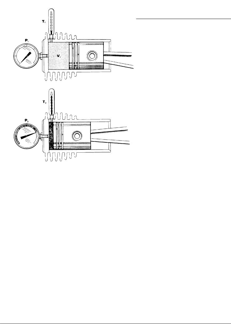
Fig. 1 Pressure-- and temperature increase
When the piston moves into the cylinder, the pressure rises in the cylinder. At the same time however, the temperature of the enclosed gas also rises. This is a basic physical law (Gay--Lussac).
Since with increasing pressure, the occuring temperatures would soon reach inadmissibly high values, the compression has to be divided into various stages. After every stage the gas is cooled back to approx. 10 -- 15 °C above ambient temperature. This is the main reason for designing compressors with 3 or 4 stages.
2
Operator’s Manual
By dividing the compression work into various stages it results in a lower power requirment. This is visible in the p--v diagram. Fig. 2 shows the power requirement with a theoretical 1 stage compression to 200 bar.
Fig. 3 shows the power requirement with a 3 stage compression and the saved work.
P |
Ideal theoretical |
|
isothermal compression |
200 bar
actual polytropic compression
|
1 bar |
|
|
|
|
|
|
|
V |
Fig. 2 |
P--V Diagram |
|
|
|
|
P |
|
P |
saving of work |
|
3. Stage |
|
||
200 bar |
200 bar |
|
||
|
|
|||
|
|
2. Stage |
|
|
|
|
1. Stage |
|
|
|
1 bar |
|
1 bar |
|
|
|
V |
|
V |
Fig. 3 |
Saving of work |
|
|
|
By dividing the compression work it not only saves energy, but it also increases the operating safety due to a lower thermical load.
3

Operator’s Manual
1.3.DESIGN AND MODE OF OPERATION
1.3.1.Design
The compressor unit comprises the following major assemblies:
•compressor block
•drive motor
•filter set
•base and frame assembly with instrument/filling panel
•electric control systema)
•electronic monitoring systema)
•automatic condensate draina)
1.3.2.Mode of operation; air flow diagram
The path of the air through the compressor system is shown in the following air flow diagrams.
a) optional extra according to order
4

Operator’s Manual
1.3.3.Air flow diagram 3-stage
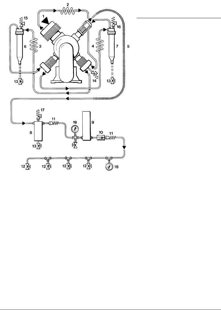
Fig. 4 |
Air flow diagram Purus, Utilus 10 and Junior |
|
|
|
1 |
Telescopic air intake |
12 |
Final pressure safety valve |
|
2 |
Intake filter |
13 |
Central filter assembly |
|
3 |
Cylinder 1st stage |
14 |
TRIPLEX longlife cartridge |
|
4 |
Cylinder 2nd stage |
15 |
Condensate drain valve |
|
5 |
Cylinder 3rd stage |
16 |
Pressure maintaining valve |
|
6 |
Inter--cooler 1st/2nd stage |
17 |
Filling hose |
|
7 |
Inter--cooler 2nd/3rd stage |
18 |
Filling valve |
|
8 |
Intermediate separator 2nd/3rd stage |
19 |
Final pressure gauge |
|
9 |
After--cooler |
20 |
Safety valve, final pressure PN 200a) |
|
10 |
Safety valve 1st stage |
21 |
Change--over devicea) |
|
11 |
Safety valve 2nd stage |
|
|
|
|
|
|
a) |
optional extra |
5

Operator’s Manual
Fig. 5 |
Air flow diagram Utilus, Capitano und Mariner |
|
|
|
1 |
Intake filter |
13 |
TRIPLEX longlife cartridge |
|
2 |
Cylinder 1st stage |
14 |
Condensate drain valve |
|
3 |
Cylinder 2nd stage |
15 |
Pressure maintainig valve |
|
4 |
Cylinder 3rd stage |
16 |
Filling hose |
|
5 |
Inter--cooler 1st/2nd stage |
17 |
Filling valve |
|
6 |
Inter--cooler 2nd/3rd stage |
18 |
Final pressure gauge |
|
7 |
After--cooler |
19 |
Change--over devicea) |
|
8 |
Safety valve 1st stage |
20 |
Safety valve, final pressure PN 200a) |
|
9 |
Safety valve 2nd stage |
a) |
|
|
10 |
Final pressure safety valve |
optional extra |
||
11Intermediate separator 2nd/3rd stage
12Central filter assembly
6
Operator’s Manual
1.3.4.Air flow diagram 4-stage
Fig. 6 |
Air flow diagram K14, K15, K150, K180 |
|
|
|
1 |
Intake filter |
11 |
Non--return valve |
|
2 |
Inter--cooler 1st/2nd stage |
12 |
Filling valve |
|
3 |
Inter--cooler 2nd/3rd stage |
13 |
Condensate drain valve (manual) |
|
4 |
Inter--cooler 3rd/4th stage |
14 |
Safety valve, intermediate pressure 2nd stage |
|
5 |
After--cooler |
15 |
Safety valve, intermediate pressure 3rd stage |
|
6 |
Intermediate separator 2nd/3rd stage |
16 |
Safety valve, intermediate pressure 4th stage |
|
7 |
Intermediate separator 3rd/4th stage |
17 |
Safety valve, final pressure |
|
8 |
Oil and water separator |
18 |
Pressure gauge, final pressure |
|
9 |
Purifier |
|
19 |
Venting valve with pressure gauge |
10 |
Pressure maitaining valve |
|
|
|
An additional intermediate separator, 1./2. stage is available for operation at high temperatures (e.g.: installation in subtropical countries) and high humidity.
The order number can be obtained through our technical customer service, Tel. 089--78049 175
7

Operator’s Manual
NOTES
8

Operator’s Manual
2.SAFETY REGULATIONS
2.1.GENERAL
WARNING
Never open filling or shut-off valves when under pressure and not connected as highly compressed emerging air can cause serious accidents.
WARNING
Ensure intake air is free from noxious gas, exhaust fumes and solvent vapour. Use an intake hose and ensure that it is mounted in such a way as to avoid taking in any noxious substances.
WARNING
Filling hoses must be in satisfactory condition and threads undamaged. Pay particular attention to damage on the interface from hose fitting to hose. If the rubber is scored, hose must be discarded otherwise water can enter and attack wire gauze causing it to rust and thus endangering pressure tightness.
CAUTION
Always shut down and decompress the complete system prior to carrying out any work on the compressor. Working on compressor units requires the necessary expert knowledge!
CAUTION
Check the complete system for leakage from time to time by brushing all fittings and couplings with soapy water or spraying with leak test spray. Repair any leakage.
CAUTION
Always disconnect the system from mains supply prior to carrying out any work on compressor systems with electric drive motor.
CAUTION
Never repair pressure lines by soldering or welding.
CAUTION
Do not use any toxic substances like gasoline or acetone or similar to clean the compressor unit or any of its parts.
9

Operator’s Manual
2.2.NOTES AND WARNING SIGNS
Notes and warning signs displayed on compressors according to model, application or equipment.
WARNING
Hot surfaces, do not touch!
Danger of burning by touching cylinders, cylinder heads and pressure lines of individual compressor stages.
WARNING
High voltage!
Life threatening danger of electric shock. Maintenance work on electric units or operating equipment may only be carried out by a qualified electrician or by a person instructed and supervised by a qualified electrician according to electrical regulations.
WARNING
Automatic compressor control, unit may start--up without warning!
Before carrying out maintenance and repair work, switch off at the main switch or disconnect from the mains and ensure unit will not restart.
MANDATORY
Instructions must be read by persons operating the machinery!
The instruction manual supplied and all other applicable instructions, regulations etc. must be read and understood by operating personnel before using the machine.
MANDATORY
Hearing protectors must be worn!
Hearing protectors must be worn when working on a machine which is running.
NOTE
Ensure correct direction of rotation!
When switching on the machine, check the arrow to ensure correct direction of rotation of the drive motor.
2.3.IDENTIFYING THE SAFETY NOTICES
Important instructions concerning the endangerment of personnel, technical safety and operating safety will be specially emphasized by placing the following signs before the instructions.
|
This notice is used with maintenance |
|
WARNING |
||
work and operating procedures and must |
||
|
be adhered to exactly in order to avoid |
|
|
endangering personnel. |
This notice must be complied with in order to avoid damage to or destruction of the machine or its equipment.
NOTICE
2.4.FUNDAMENTAL SAFETY NOTICES
Authorized use
•The machine / unit is built according to state of the art technology and established safety technical regulations. Nevertheless, its use can cause danger to life and limb of the operator or third parties or damage to the machine and other equipment.
•Operate the machine / unit only in technically perfect condition in accordance with regulations and safety and danger notices detailed in the instruction manual! In particular, immediately correct faults (or have them corrected) which can impair safety!
•The machine / unit is exclusively for the compression of mediums (air/gas) specified in section A, chapter 1.3. “Technical data”. Any other medium or use outside that specified is not authorized. The manufacturer / supplier is not liable for damage resulting from this. The user alone is responsible for this risk. Authorization for use is also under the condition that the instruction manual is complied with and inspection and maintenance requirements are enforced.
Organizational measures
•Keep the instruction manual to hand near the machine / unit at all times in the relevant holder.
•In addition to the instruction manual, observe and comply with universally valid legal and other obligatory regulations regarding accident prevention and environment protection. This can involve, for example, contact with hazardous substances or the provision / wearing of personal protective equipment.
•In addition to the instruction manual, provide supplementary instructions for supervision and monitoring duties taking into consideration exceptional factors e.g. with regard to organization of work, production, personnel employed.
•Personnel engaged to operate the machine must have read the instruction manual before beginning work, especially the safety notices chapter. When work is already underway it is too late. This is particularly relevant for temporary personnel, e.g. maintenance personnel.
•At the very least, supervise temporary personnel’s work in accordance with the instruction manual, taking into account safety and danger factors.
•Personnel may not wear long hair loose, loose clothing or jewellery, including rings. There is a danger of injury
10

Operator’s Manual
through, for example, these getting caught or being pulled into the equipment.
•As far as necessary or according to regulations, use personal protective equipment.
•Observe all safety and danger notices on the machine / unit.
•Keep all safety and danger notices on the machine / unit complete and in readable condition.
•If there are any modifications to the machine / unit or operating conditions which may affect safety, stop the machine / unit immediately and inform the department / person responsible of the fault.
•No modifications may be made to the machine / unit which could impair safety without first obtaining permission from the suppliers. This is also the case with regard to installation and adjustment of safety devices and valves as well as welding of piping and reservoirs.
•Spare parts must always comply with the technical requirements specified by the manufacturer. This is always guaranteed with original spare parts.
•Do not carry out programme changes (software) to the programmable control system.
•Piping must be thoroughly checked (pressure and visual inspection) by the operator at appropriate time intervals, even if no safety related faults have been noticed.
•Intervals stipulated or given in the instruction manual for recurring checks / inspections must be adhered to.
•It is absolutely essential that the workplace is appropriately equipped for maintenance measures.
•Make sure location and operation of fire extinguishers is known.
•Pay attention to fire warning and fire fighting procedures.
Qualifications, fundamental duties
•Work on / with the machine / unit may only be carried out by reliable personnel. Observe the legal minimum age permissible.
•Only employ trained personnel, clearly establish responsibility of personnel for operation, maintenance and repairwork.
•Ensure that only trained personnel work with the machine.
•Establish the responsibilities of the machine operator and establish a procedure for him to inform a third person of unfavourable safety conditions.
•People who are being trained or introduced to the job should only be allowed to work with the machine / unit under constant supervision of an experienced person.
•Work on the electrical equipment of the machine / unit may only be carried out by a qualified electrician or by an instructed person under the direction and supervision of a qualified electrician according to electrotechnical regulations.
•Work on gas equipment may only be carried out by qualified personnel.
Safety notices for operation
•Do not carry out any work if safety is questionable.
•Meet all requirements demanding that the machine / unit is only operated in safe and good working order. Only operate
the machine if all protective and safety equipment, e.g. all detachable protective equipment, emergency shut--down devices, soundproofing is provided and in good working order.
•At least once every day, check the machine / unit externally for damage and faults. Inform the department / person responsible immediately if anything is not as is should be (including operation). If necessary, shut the machine down immediately and make it safe.
•If there are any malfunctions, shut the machine / unit down immediately and make it safe. Correct faults immediately (or have them corrected).
•Observe switching on and off processes and monitoring indications according to the instruction manual.
•Before switching on / starting up the machine / unit, ensure that no one can be put at risk through running the machine
/unit.
•Carry out the setting, maintenance and inspection processes at the intervals specified in the instruction manual, including replacement of parts / equipment. This work may only be carried out by qualified personnel.
•Before carrying out any exceptional work or repairwork, operating personnel should be informed. Call the supervisor.
•For all work concerning operation, change in production, conversion or regulating of the machine / unit and its safety measures such as inspection, maintenance and repairwork, observe the switching on and off processes in the instruction manual and the notices for maintenance work.
•Clear and make the maintenance area safe as far as necessary.
•If the machine / unit is completely switched off for maintenance and repairwork, ensure that it is protected from unexpected start--up. Turn off main control device and remove the key and / or display a warning sign on the main switch.
•When replacing individual parts and larger assembly groups, they must be carefully fastened to the lifting device so that there is no risk of danger. Use only suitable and technically perfect lifting devices and equipment with sufficient lifting power and strength. Do not linger or work under suspended loads.
•Only entrust an experienced person with the fixing of loads and guiding of crane drivers. The person guiding must remain within sight or in contact with the operator.
•For assembly work above body height, use appropriate safety approved equipment, e.g. ladders and platforms. Do not climb on machine parts. For maintenance work at high levels, wear a safety harness.
•Clean oil, fuel or care products from the machine, in particular the connections and screw joints, before carrying out maintenance / repairwork. Do not use aggressive cleaning fluid. Use a fibre--free cleaning cloth.
•Before cleaning the machine with water or jet of steam (high pressure cleaner) or detergent, cover / seal all openings which for safety and/or operating reasons no water / steam
/detergent may penetrate. Electric motor and switch cabinets are particularly at risk.
•When cleaning the operating room, ensure that the temperature sensors of the fire alarm and sprinkler system do not come into contact with hot cleaning fluid, in order to avoid triggering the sprinkler system.
11

Operator’s Manual
•Completely remove all covers / seals after cleaning.
•After cleaning, check all pressure lines for leaks, loose connections, wear and damage. Immediately eliminate any faults.
•Always retighten any screw connections loosened for maintenance or repairwork.
•If it is necessary to remove safety devices for maintenance and repairwork, these must be replaced and checked immediately after completion of the maintenance or repairwork.
•Ensure safe and environmentally friendly disposal of consumables and old parts.
Particular areas of danger
•Use only original fuses with specified current rating. If there is a failure in the electric energy supply, shut the machine / unit down immediately.
•Work on electric units or operating equipment may only be carried out by a qualified electrician or by a person under the instruction and supervision of a qualified electrician according to electric technical regulations.
•Machines and unit parts which must undergo inspection, maintenance and repairwork, must be disconnected from the mains supply, if specified. Parts which have been disconnected must first be checked for voltage, then earthed and short--circuited and isolated from live neighbouring parts.
•The electrical equipment of a machine / unit must be regularly checked. Defects, such as loose screw connections or burnt wires, must be rectified immediately.
•If work is to be carried out on live parts, work with a second person who can operate the emergency off switch or the main switch in the case of an emergency. Close off the work area with a red and white safety chain and a warning sign. Only use voltage isolated tools.
•Only carry out welding, burning and grinding work on the machine / unit when specifically approved. There can, for example, be a risk of fire or explosion.
•Before carrying out welding, burning or grinding work, clean the machine / unit and surrounding area from dust and flammable material and ensure there is adequate ventilation (danger of explosion!).
•When working in small rooms, observe any national regulations.
•Only personnel with particular knowledge and experience with pneumatics may carry out work on pneumatic equipment.
•Check all pressure lines, hoses and screw connections regularly for leaks and visible damage. Immediately repair any damage. Escaping air or gas under pressure can cause injury and fire.
•Depressurize system and pressure lines before commencing repairwork.
•Pressurized air lines must be laid and mounted by qualified personnel. Connections must not be mixed up. Fittings, length and quality of the piping must correspond to requirements.
•Soundproofing equipment on the machine / unit must be in place and functional during operation.
•The stipulated hearing protectors must be worn.
•With regard to oil, grease and other chemical substances, observe the relevant safety regulations for the product.
•For loading, only use lifting device and equipment with sufficient lifting power and strength.
•Appoint trained guide personnel for lifting operations.
•Machines may only be lifted with a lifting device and by trained personnel according to instructions in the instruction manual (fixing points for fixing equipment etc.).
•Use only suitable transporters with sufficient carrying power.
Secure the load properly. Use suitable fixing points.
•If necessary, provide machine / unit with transportation brackets. Display the appropriate notice. Remove transportation brackets in the correct manner before taking into operation.
•Parts which need to be dismantled for transport purposes must be carefully replaced and secured before taking into operation.
•Even when moving the machine / unit only slightly, the machine / unit must be disconnected from all external energy sources. Before putting into use again, reconnect the machine to the mains according to regulations.
•When taking back into operation, proceed according to the instruction manual.
Notices of danger regarding pressure vessels
•Never open or loosen pressure vessel lids or pipe connection parts under pressure; always depressurise the vessel or the unit.
•Never exceed the permissible operating pressure of the vessels!
•Never heat the vessels or any of their parts above the stated, maximum operating pressure.
•Always exchange damaged pressure vessels completely. Individual parts that are subject to pressure loads cannot be purchased as spare parts, since the vessels are tested as a complete part and the documentation considers them as a whole (see pressure vessel documentation, serial-- numbers!).
•Always pay attention to the permissible operating mode of the pressure vessels.
We differentiate:
-- vessels for static load
-- vessels for dynamic load Vessels for static load:
These pressure vessels are permanently under virtually constant operating pressure; the fluctuations of pressure are very small.
Vessels for this type of load are not marked in a particular way and may be used as long as the vessel inspections, carried out regularly, do not uncover any safety--relevant deficiencies.
We recommend that aluminium vessels should be exchanged after 15 years at the latest.
Vessels for dynamic load:
12
Operator’s Manual
These pressure vessels may also be used under conditions of changing operating pressure. The pressure may vary between the atmospheric and the maximum admissible operating pressure.
The pressure vessel documentation and the appropriate notes in the operating manual particularly characterise vessels of this type as being adequate for dynamic loads. In the technical information for these vessels you will find specifications concerning their permissible operating period.
Due to the variation of the operating pressure, these vessels are subject to a so--called dynamic load, which puts the vessels under great stress. The change between two different pressures is called a load change or cycle. In the technical information for these vessels you will find specifications concerning the permissible number of cycles depending on the fluctuation of the operating pressure.
Having reached half the permissible number of cycles, the vessel has to be submitted to an internal check, in which the critically stressed areas of the vessels are examined by means of suitable testing methods, in order to ensure the operating safety.
After having reached the total permissible number of load cycles, the vessel must be exchanged and scrapped.
Record the number of load cycles in writing if you do not have an automatic cycle--counter.
We recommend that aluminium vessels should be exchanged after 15 years at the latest.
Please pay attention to and follow these measures, for your own safety and that of you employees and customers!
In order not to unnecessarily load the pressure vessels additionally, the non--return valves, that are meant to avoid a drop in pressure, and also the pressure maintaining valves, which should reduce big pressure fluctuations as well, should be checked regularly for internal and external tightness and functionality.
•Check the pressure vessels regularly on the inside and outside for damage from corrosion.
•Be particularly careful with second--hand pressure vessels, when their previous operating mode is not specifically clarified.
2.5.SAFETY REGULATIONS (EC; partly Germany, only)
A compressor is identified by German law as being a filling system if pressure cylinders are filled by the system, especially when these cylinders are made available for third parties. The start--up and operation of compressor systems for use as filling stations is governed by the following regulations:
a- Pressure vessel directive (Directive 97/23/EC) of 29.05.1997
b- Operating safety regulations (BetrSichV) of 27.09.2002
c- Machine safety law (GSG) as of 11.05.2001
d- 14th regulation to machine safety law (14. GSGV - pressure vessel regulation) of 03.10.2002
e- Technical regulations for pressure gases (TRG 400, 401, 402, 730).
If a high pressure compressor is used for filling pressure vessels or for the supply of pneumatic systems, the following regulations apply:
f- Accident Prevention Regulations (UVV):
•UVV compressors (VBG 16).
Copies of the above regulations are available through the usual outlets, e.g. in Germany from:
Carl Heymanns Verlag
Luxemburger Str. 449
50939 Köln
Beuth--Vertrieb GmbH
Burggrafenstr. 4 -- 7
10787 Berlin
The manufacturer has complied with all applicable regulations and the unit is prepared accordingly. If desired, we offer at our Munich site a partial acceptance test according to § 14 BetrSichV. Please contact our Technical Service Department with regard to this. They can also supply our leaflet “IMPORTANT NOTES FOR CERTIFICATION”.
According to the operation safety regulations (BetrSichV), all compressor units which will be used as filling stations must undergo an acceptance test by a professional at their location before bringing them into service. If pressure vessels (bottles) are to be filled by the compressor for a third party then the appropriate permission must be obtained from the responsible authority before the acceptance test. As a rule, this is the factory inspectorate. The procedure for obtaining permission is according to TRG 730, guidelines for permission to set up and operate filling stations. The test certificates and documents delivered with the compressor are important and may be requested during the procedure for obtaining permission. In addition, the documents belonging to the unit are important for recurrent inspections and should therefore be carefully kept.
Inspections in accordance with the regulations for prevention of accidents will be carried out by the manufacturer or by a specialist.
No guarantees whatsoever are valid for damage caused or favoured by the non--consideration of these directions for use.
We strongly emphasize these regulations.
13
 Loading...