

Page 1

OPERATOR MANUAL
®
Basil
(2008-02-04) P122996-163
3600 Bedding Dispenser
Page 2

A WORD FROM STERIS CORPORATION
This manual contains important information on the proper use of the
®
Basil
3600 Bedding Dispenser. Refer to SECTION 5, ROUTINE MAIN-
TENANCE, for instructions in routine care of this bedding dispenser.
All personnel and department heads are urged to carefully
review and become familiar with the Safety Precautions and
instructions contained herein. These instructions are important to
protect the health and safety of personnel operating this bedding
dispenser and should be retained in a conveniently accessible area
for quick reference. This equipment is specifically designed only for
the uses outlined in this manual.
Complete instructions for uncrating and connecting utilities, as well
as the equipment drawing, have been provided. If they are missing,
contact STERIS for replacement copies, providing the serial and
model numbers of the bedding dispenser.
Advisory IMPORTANT: A listing of the Safety Precautions to be observed
when operating and servicing this bedding dispenser can be found in
S
ECTION 1 of this manual. Do not operate the equipment until you
have become familiar with this information.
Any alteration of this equipment not authorized or performed by
STERIS will void the warranty. Alteration of this equipment which
could adversely affect its operation and efficacy may violate national,
state and local laws or regulations.
Indications For Use The Basil 3600 Bedding Dispenser is an automatic, conveyorized
unit designed to dispense bedding into animal cages as they pass
through the unit. The dispensers are capable of handling most solid
bedding used in the care of laboratory animals.
©2008, STERIS Corporation. All rights reserved. Printed in Canada.
Introduction Operator Manual 122996-163
i
Page 3
Service Information A thorough preventive maintenance program is essential to help
ensure safe and proper equipment operation. Customers are
encouraged to contact STERIS concerning our comprehensive
annual maintenance program. Under the terms of the program, preventive maintenance, adjustments and replacement of worn parts
are performed on a scheduled basis to help ensure equipment performance at peak capability and to help avoid untimely or costly
interruptions.
STERIS maintains a global staff of well-equipped, qualified service
technicians to provide this service, as well as expert repair services.
Please contact STERIS for details.
Corporation STERIS
Can ada
Québec, Qc, CANADA
The base language of this document is
ENGLISH. Any translations must be
made from the base language document.
ISO 13485
ISO 9001
Certified
Facility
ii
122996-163 Operator Manual Introduction
STERIS Limited
STERIS House
Jays Close
Viables
Basingstoke
Hampshire
RG22 4AX
United Kingdom
Sales and Service:
STERIS Corporation
5960 Heisley Road
Mentor, Ohio 44060
440-354-2600 • 800-444-9009
www.steris.com
Page 4

TABLE OF CONTENTS
Section
Number Description Page
A WORD FROM STERIS CORPORATION..................................................................i
Advisory............................................................................................................................................................ i
Indications For Use........................................................................................................................................... i
Service Information...........................................................................................................................................ii
1 SAFETY PRECAUTIONS ......................................................................................1-1
2 INSTALLATION VERIFICATION...........................................................................2-1
2.1 General ................................................................................................................................................... 2-1
2.2 Installation Checklist............................................................................................................................... 2-1
2.3 Technical Specifications......................................................................................................................... 2-2
2.3.1 Voltage, Amperage and Power Consumption................................................................................. 2-2
2.3.2 Permissible Environmental Conditions............................................................................................ 2-2
2.3.3 Seismic Anchorage System ............................................................................................................ 2-2
3 COMPONENT IDENTIFICATION...........................................................................3-1
3.1 General ................................................................................................................................................... 3-1
3.2 Component Identification ....................................................................................................................... 3-1
3.2.1 Cage Conveyor System .................................................................................................................. 3-1
3.2.2 Bedding Dispenser System ............................................................................................................ 3-1
3.2.3 Service Access Panels and Cleanout Door .................................................................................... 3-1
3.2.4 Drain Connection and Removable Debris Tray .............................................................................. 3-1
3.2.5 Adjustable Legs .............................................................................................................................. 3-1
3.2.6 Cage Flip-Over System ................................................................................................................... 3-1
3.2.7 Photoelectric Conveyor Stop........................................................................................................... 3-1
3.2.8 Control Panel................................................................................................................................... 3-3
3.2.9 Dust Collection System ................................................................................................................... 3-4
4 OPERATING INSTRUCTIONS ..............................................................................4-1
4.1 Before Operating Bedding Dispenser.................................................................................................... 4-1
4.2 Operating Bedding Dispenser ............................................................................................................... 4-1
4.3 Shutdown................................................................................................................................................ 4-2
5 ROUTINE MAINTENANCE....................................................................................5-1
5.1 General Information ................................................................................................................................ 5-1
5.2 Preventive Maintenance ......................................................................................................................... 5-2
Table of Contents Operator Manual 122996-163
Continued...
iii
Page 5

TABLE OF CONTENTS (Cont’d)
Section
Number Description Page
5 ROUTINE MAINTENANCE (Cont’d)
5.3 Weekly Cleaning..................................................................................................................................... 5-3
5.3.1 Clean Cage Conveyor Rollers ......................................................................................................... 5-3
5.3.2 Empty Dust Collection System Bag ................................................................................................5-6
5.3.3 Clean Bedding Dispenser Exterior.................................................................................................. 5-7
5.4 Weekly Maintenance .............................................................................................................................. 5-8
5.4.1 Verify Gearbox Oil Level ................................................................................................................. 5-8
5.4.2 Grease Cage Conveyor Bearings ................................................................................................... 5-9
5.4.3 Adjust Dispenser Take-Up Bearings............................................................................................. 5-10
5.4.4 Adjust Dispenser Driving Chain Tensioner ................................................................................... 5-11
5.4.5 Replace Shear Pin on Torque Limiter ........................................................................................... 5-12
6 TROUBLESHOOTING ...........................................................................................6-1
7 REPLACEMENT PARTS AND PRODUCTS ............................................................7-1
iv
122996-163 Operator Manual Table of Contents
Page 6

LIST OF ILLUSTRATIONS
Figure Description Page
Section 3: Component Identification
3-1 Basil 3600 Bedding Dispenser ......................................................................................................... 3-2
3-2 Basil 3600 Bedding Dispenser Control Panel...................................................................................3-3
3-3 Dust Collection System ..................................................................................................................... 3-4
Section 5: Routine Maintenance
5-1 Cleaning and Maintenance ............................................................................................................... 5-4
5-2 Removing Roller (Fixed End) ............................................................................................................ 5-5
5-3 Removing Roller (Removable End) ................................................................................................... 5-5
5-4 Empty Dust Collection Bag ............................................................................................................... 5-6
5-5 Verify Gearbox Oil Level ................................................................................................................... 5-8
5-6 Grease Conveyor Bearings ............................................................................................................... 5-9
5-7 Adjust Dispenser Take-Up Bearings............................................................................................... 5-10
5-8 Adjust Dispenser Driving Chain Tensioner .....................................................................................5-11
5-9 Replace Shear Pin on Torque Limiter ............................................................................................. 5-12
List of Illustrations Operator Manual 122996-163
v
Page 7

SAFETY PRECAUTIONS
The following Safety Precautions must be observed when operating or servicing this Basil® 3600 Bedding Dispenser.
WARNING indicates the potential for personal injury and CAUTION indicates the potential for damage to equipment.
For emphasis, certain Safety Precautions are repeated throughout the manual. It is important to review ALL Safety
Precautions before operating or servicing the bedding dispenser.
1
WARNING – PERSONAL INJURY AND/OR EQUIPMENT DAMAGE HAZARD:
Repairs and adjustments to this equipment must be made only by STERIS or STERIS-trained service
personnel. Non-routine maintenance performed by unqualified personnel or installation of unauthorized
parts could cause personal injury, result in improper equipment performance, void the warranty or result
in costly damage. Contact STERIS regarding service options.
Regularly scheduled preventive maintenance is required for safe and reliable operation of this equipment. Contact STERIS to schedule preventive maintenance.
WARNING – PERSONAL INJURY HAZARD:
Keep fingers and hands away from chains, gears or any other moving parts. Also avoid wearing loose
clothing that could get caught in mechanical parts.
WARNING – ELECTRIC SHOCK AND/OR BURN HAZARD:
Disconnect all utilities to dispenser before servicing. Do not service dispenser unless all utilities have
been properly locked out. Always follow local lockout-tagout and electrical safety-related work practice
standards.
Fasteners and star washers are used to ensure protective bonding continuity. Always reinstall any star
washer which may have been removed during installation or servicing.
CAUTION – POSSIBLE EQUIPMENT DAMAGE:
Do not wash conveyor rollers in water exceeding 140
Use non-abrasive cleaners when cleaning dispenser. Follow directions on container and rub in a backand forth motion (in same direction as surface grain). Abrasive cleaners are harmful to stainless steel.
°F (60°C).
Safety Precautions Operator Manual 122996-163
1-1
Page 8
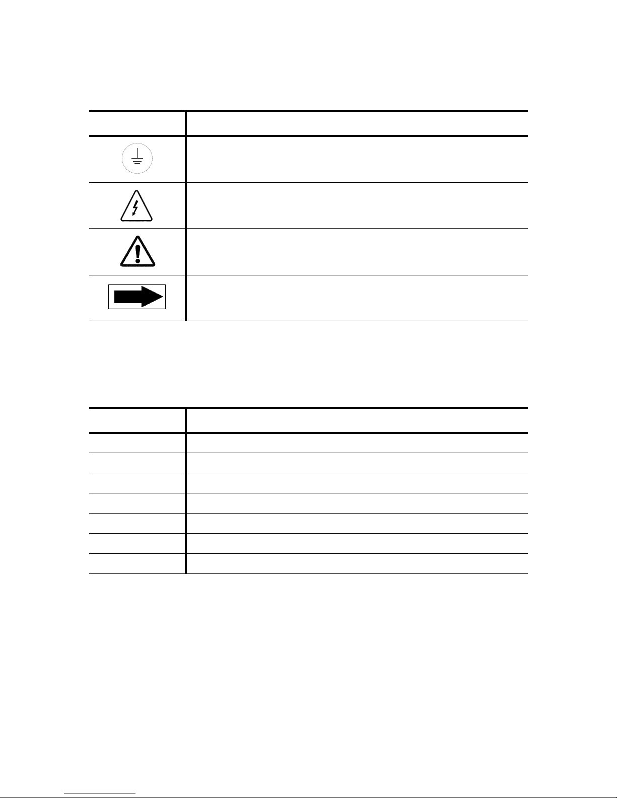
The table below contains symbols which may be on your bedding dispenser components:
Table 1-1. Definition of Symbols
Symbol Definition
Protective Earth (Ground).
Warning! Risk of Electrical Shock.
Warning. Refer to Manual For Further Information.
Rotation Direction.
The table below contains symbols which may be on the identification nameplate of your bedding dispenser:
Table 1-2. Definition of Symbols
Symbol Definition
MOD. Model Number of Bedding Dispenser.
SER. Serial Number of Bedding Dispenser.
kW Power Rating of Bedding Dispenser.
V Voltage Rating of Bedding Dispenser.
A Amperage Rating of Bedding Dispenser.
PH/Hz Phase of Bedding Dispenser / Frequency Rating of Bedding Dispenser.
WIRE X + PE Number of Wires [X] in the Electrical Cable and Protective Ground Wire.
1-2
122996-163 Operator Manual Safety Precautions
Page 9

2
INSTALLATION VERIFICATION
2.1 General An equipment drawing (122-998-267 or 122-998-283), showing all
utility and space requirements, was supplied with the Basil
Bedding Dispenser. The clearance space specified on the equipment drawing is necessary for ease of installation and to help ensure
proper operation and maintenance of equipment. If document is
missing or misplaced, contact STERIS, giving the serial and model
numbers of the bedding dispenser. A replacement copy will be sent
promptly.
2.2 Installation
Checklist
After bedding dispenser has been installed by a qualified service
technician, complete the following checklist to help ensure complete
and correct installation. If desired, contact STERIS to schedule a
demonstration of proper equipment operation.
❑ Disconnect switch (not by STERIS), capable of being locked in
OFF position only, is installed in the electrical supply line in the
same room as the bedding dispenser, and within 10 feet (3 m) of
the electrical control box.
❑ Bedding dispenser is positioned, as shown on the equipment
drawing, with the required service clearance space and in relation to building supply lines.
❑ Electrical supply for bedding dispenser is as specified on the
equipment drawing.
❑ Both conveyor motors (loading/unloading drive motor and bed-
ding conveyor motor) rotate in the direction shown by the arrow.
❑ Verify exhaust guard, elbow and dust bag are in proper position.
®
3600
Installation Verification Operator Manual 122996-163
❑ Verify cage flip-over system is firmly installed and in proper posi-
tion.
❑ Verify photoelectric switch is properly installed at the end of the
unload conveyor.
2-1
Page 10

2.3 Technical
Specifications
These specifications are intended to describe the technical information given on the bedding dispenser identification nameplate and to
state other relevant information. Verify equipment drawing (122-998267 or 122-998-283) or identification nameplate, located in chemical
storage compartment, for proper voltage and amperage.
2.3.1 Voltage, Amperage and
Power Consumption
2.3.2 Permissible
Environmental Conditions
The Basil 3600 Bedding Dispenser operates on:
• 208 V, 60 Hz, three-phase, neutral, four-wire
• 480 V, 60 Hz, three-phase, three-wire
Maximum current and power consumptions are:
Amp kW
• 208 V
• 480 V
Refer to Uncrating/Installation Instructions (P122997-217) for proper
connection.
This equipment is designed to give optimal results in an environment
where maximum relative humidity is 80% for temperatures up to 88ºF
(31ºC) decreasing linearly to 50% relative humidity at 104ºF (40ºC).
13.9 2.6
5.6 2.7
2.3.3 Seismic Anchorage
A seismic anchorage system is available for high-risk seismic zones.
System
2-2
122996-163 Operator Manual Installation Verification
Page 11

3
COMPONENT IDENTIFICATION
3.1 General Before operating the Basil
to become familiar with the location and function of all components
and controls (see Figures 3-1, 3-2 and 3-3).
3.2 Component
See Figure 3-1.
®
3600 Bedding Dispenser, it is important
Identification
3.2.1 Cage Conveyor System The cage conveyor system includes twenty-six 1-1/2" (38 mm)
diameter PVC rollers to move the cages. The rollers are designed for
free movement on hub and easy removal for cleaning purposes. The
cage conveyor system motor is 1/6-hp speed reducer, ac, 1 ph.
3.2.2 Bedding Dispenser
System
3.2.3 Service Access Panels
and Cleanout Door
The bedding dispenser system includes a heavy chain belt that
allows bedding to pass through the chain without jamming in the
drive sprockets. Low-friction UHMW guides and wear pads provide
smooth, quiet travel throughout the dispensing cycle.
The dispenser belt motor is 1-hp, variable speed motor.
The four service access panels allow sprocket and chain repair of
the cage conveyor system rollers. Unload end of the dispenser has
two access panels. Loading hopper has a hinged cover. The bedding
dispenser belt has a removable cover.
The cleanout door, on unload end, allows access to lower hopper.
3.2.4 Drain Connection and
Removable Debris Tray
3.2.5 Adjustable Legs The adjustable legs allow leveling of the bedding dispenser and
3.2.6 Cage Flip-Over System The system is provided at load end of the Basil 3600 Bedding Dis-
3.2.7 Photoelectric Conveyor
Component Identification Operator Manual 122996-163
Stop
The drain connection with plug in lower hopper helps with cleaning
and draining of the bedding dispenser.
adjusting of the conveyor height.
penser to grab the cages coming out of the Basil
Washer, and flip them right side up onto the cage conveyor before
filling them with bedding.
A photoelectric switch can be provided at the unload end of the
cage conveyor to stop rollers when an item reaches the end of the
cage conveyor.
®
6700 Tunnel Cage
3-1
Page 12
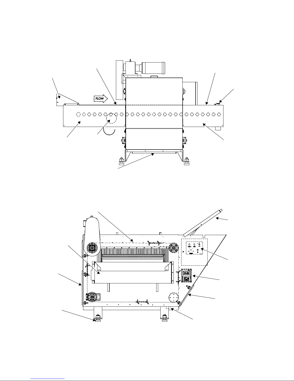
SIDE VIEW
FRONT VIEW
(Load Side)
Cage Flip-Over
System
Cage Conveyor
(Load)
Cage Conveyor
(Unload)
Photoelectric
Conveyor Stop
Service Access Panel
(One on Each Side of
Roller Conveyor)
Ventilation
System
Service Access Panel
(One on Each Side of
Roller Conveyor)
Drain Connection
Bedding Dispenser Belt
Bedding Hopper
Access Panel
Control Panel
Cleanout Door
Service Access
Panel
Adjustable Leg
Service Access Panel
(One on Each Side of
Roller Conveyor)
Drain Connection
Figure 3-1. Basil 3600 Bedding Dispenser
Drive
3-2
122996-163 Operator Manual Component Identification
Page 13
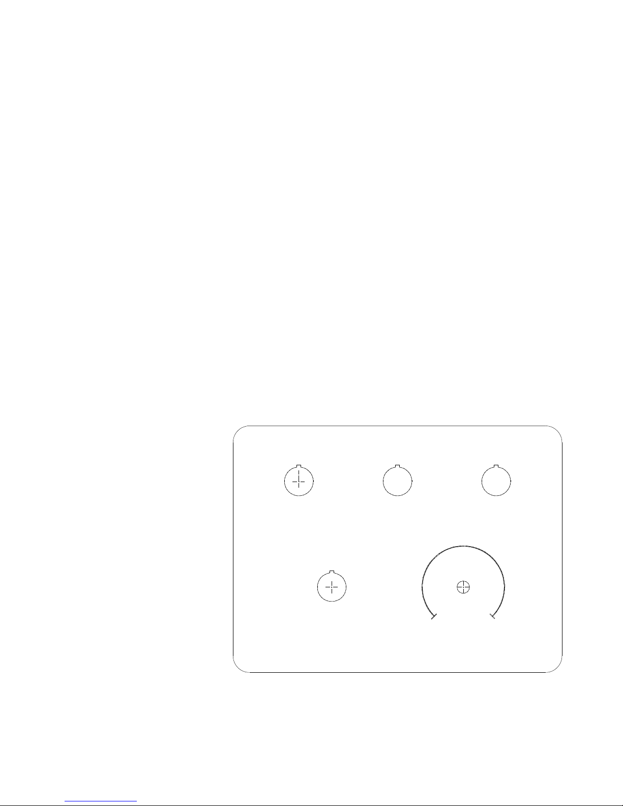
3.2.8 Control Panel See Figure 3-2.
Figure 3-2. Basil 3600 Bedding Dispenser Control Panel
OFF
ON
Power
Dispenser
ON/OFF
Dust Collector
ON/OFF
Unit
STOP
Low
High
Dispenser Speed
Adjustment
• Power ON/OFF selector switch: turning Power ON/OFF selector
switch to ON position activates control and unit operations.
Turning Power ON/OFF selector switch to OFF position cuts
electrical supply to the unit.
• Unit STOP pushbutton (red): Stops cage conveyor rollers,
bedding dispenser belt and dust collection system operations.
When rollers, belt and dust collection system are stopped, the
corresponding red indicator light is ON.
• Dispenser ON/OFF pushbutton: Press Dispenser ON/OFF
pushbutton to ON position to activate the bedding dispenser belt
drive motor. Press Dispenser ON/OFF pushbutton to OFF
position to cut electrical supply to bedding dispenser belt drive
motor.
• Dispenser Adjustment knob: Turn Dispenser Adjustment
knob to the left to decrease bedding flow. Turn Dispenser
Adjustment knob to the right to increase bedding flow.
• Dust Collector ON/OFF pushbutton: Press Dust Collector ON/
OFF pushbutton to ON position to activate dust collection system.
Press Dust Collector ON/OFF pushbutton to OFF position to cut
electrical supply to dust collection system.
• Indicator lights: An indicator light is linked to the unit electrical
supply power, dispenser, unit and dust collection system. When
an indicator light is ON, corresponding system is activated.
Component Identification Operator Manual 122996-163
3-3
Page 14
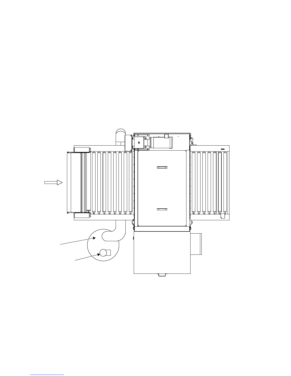
3.2.9 Dust Collection System See Figure 3-3.
Figure 3-3. Dust Collection System
Blower
Dust Collection
Drum
TOP VIEW
The system removes dust generated by the filling operation and
eliminates the need for connection to building exhaust. The system
includes a 2-hp blower and a 55-gallon drum connected to the
bedding dispenser ventilation system. The dust collection system
has a Dust Collector ON/OFF pushbutton on the control panel.
.
3-4
122996-163 Operator Manual Component Identification
Page 15
4
OPERATING INSTRUCTIONS
WARNING–PERSONAL INJURY
HAZARD: Keep fingers and
hands away from chains,
gears or any other moving
parts. Also avoid wearing
loose clothing that could get
caught in mechanical parts.
IMPORTANT: A listing of the Safety Precautions to be observed when operating and servicing this bedding
dispenser can be found in S
familiar with this information.
ECTION 1 of this manual. Do not operate the equipment until you have become
4.1 Before Operating
Bedding Dispenser
4.2 Operating Bedding
Dispenser
Verify hopper is filled with bedding. Fill as necessary as follows:
1. Open hinged cover (refer to Figure 3-1).
2. Fill bedding up to wire netting.
Maximum capacity 11-1/2 ft
3. Close hinged cover.
Refer to Figure 3-2 for control location.
1. Position Power ON/OFF selector switch to ON.
2. Pull Unit STOP pushbutton (red) to start conveyor.
3. After pulling Unit STOP pushbutton, wait two seconds and push
Dispenser ON/OFF pushbutton to activate bedding dispenser
system.
4. With Dispenser ON/OFF pushbutton in OFF position, you may
run bedding dispenser conveyor without dispensing material.
5. Press Dust Collector ON/OFF pushbutton to activate dust collection system.
6. If necessary, adjust amount of bedding desired in cages using
Dispenser Adjustment knob to increase/decrease bedding flow.
7. Place cages top side up on conveyor rollers.
3
(0.3 m3) of bedding.
Operating Instructions Operator Manual 122996-163
NOTE: Cages of cage flip-over system are automatically flipped
from inverted position to top side up position when exiting Basil
6700 Tunnel Cage Washer.
8. As cages pass through unit, a controlled level of bedding material is dispensed into cages.
NOTE: Cages can pass beneath hopper in any random pattern
and will still be filled with the same amount of bedding per square
inch.
9. When cages are filled with bedding, remove cages from unload
conveyor rollers.
With photoelectric conveyor stop system, conveyor rollers stop
automatically when a cage reaches end of unload conveyor.
IMPORTANT: Conveyor, bedding dispenser and dust collection
system operations may be halted at any time by pressing red
Unit STOP pushbutton.
4-1
®
Page 16

4.3 Shutdown At the end of the day:
1. Press Dispenser ON/OFF pushbutton to OFF.
2. Press Dust Collector ON/OFF pushbutton to OFF.
3. Position Power ON/OFF selector switch to OFF.
4. Clean bedding dispenser as explained in S
MAINTENANCE.
ECTION 5, ROUTINE
4-2
122996-163 Operator Manual Operating Instructions
Page 17
5
ROUTINE MAINTENANCE
WARNING–PERSONAL INJURY
AND/OR EQUIPMENT DAMAGE
HAZARD: Regularly scheduled
preventive maintenance is
required for safe and reliable
operation of this equipment.
Contact STERIS to schedule
preventive maintenance.
WARNING–ELECTRIC SHOCK
AND/OR BURN HAZARD:
• Disconnect all utilities to
dispenser before servicing.
Do not service dispenser
unless all utilities have been
properly locked out. Always
follow local lockout-tagout
and electrical safety-related
work practice standards.
• Fasteners and star washers
are used to ensure protective
bonding continuity. Always
reinstall any star washer
which may have been
removed during installation
or servicing.
IMPORTANT: A listing of the Safety Precautions to be observed when operating and servicing this bedding
dispenser can be found in S
familiar with this information.
ECTION 1 of this manual. Do not operate the equipment until you have become
5.1 General
Information
Procedures described in this section should be performed at regular
intervals as indicated.
Due to local conditions (air quality, amount of usage), more frequent
maintenance than indicated may be required. Customer should
maintain a record of all maintenance procedures performed on the
®
Basil
3600 Bedding Dispenser.
Should a problem occur, refer to S
Refer to S
ment parts list.
NOTE: Never permit unqualified persons to service the bedding dispenser.
ECTION 7, REPLACEMENT PARTS AND PRODUCTS, for replace-
ECTION 6, TROUBLESHOOTING.
Routine Maintenance Operator Manual 122996-163
5-1
Page 18

5.2 Preventive
Maintenance
Table 5-1. Preventive Maintenance Guide
Table 5-1 is to be used as a preventive maintenance record and,
along with the instructions in this section, as a guide to performing
preventive maintenance.
IMPORTANT: Preventive Maintenance is not covered under warranty.
Recommended frequency of inspection is indicated in the right column. Usage and
utility conditions may require more or less frequent inspections.
Suggested
Frequency
1.0 PREPARATION FOR PREVENTIVE MAINTENANCE
1.1 Discuss equipment with operators. As required
1.2 Follow appropriate safety procedures; prepare unit for preventive maintenance. As required
2.0 MISCELLANEOUS CHECKS
2.1 Inspect mechanical parts for obvious wear. Replace parts if necessary.* 6 X/ year
2.2 Verify proper operation of pushbuttons and selector switch (refer to S
2.3 Verify gearbox oil level as described in S
ECTION 5.4.6 X/ year
ECTION 3.2.8). 6 X/ year
3.0 BEDDING DISPENSER BELT
3.1
Verify proper amount of bedding is being dispensed by unit into cages. Adjust
Dispenser Adjustment knob as necessary.
6 X/ year
3.2 Verify shovel-type blades are bringing bedding to top of hopper. 6 X/ year
3.3 Grease dispenser belt bearings as described in S
ECTION 5.4.4 X/ year
3.4 Verify proper adjustment and tracking on conveyor take-up bearings. 6 X/ year
3.5 Inspect dispenser belt for looseness. Tighten if necessary. 6 X/ year
4.0 CAGE FLIP-OVER SYSTEM
4.1 Inspect cage flip-over system for component looseness. Tighten if necessary. 6 X/ year
4.2 Inspect drive chain for looseness. Tighten if necessary. 6 X/ year
4.3 Inspect mechanical parts for obvious wear. Replace parts if necessary.* 6 X/ year
4.4 Grease drive chain. As required
5.0 FINAL CHECKOUT AND TEST
5.1
Clean dirt and lint from components. Verify all wiring, terminals and socket connections for damage or fraying.
6 X/ year
5.2 Verify unit has proper labels (caution, warning). 6 X/ year
5.3 Run a few cages to verify proper operation. 6 X/ year
5.4
Reinstall any panel or cover removed. Inspect area to ensure removal of all materials
used during inspection.
6 X/ year
5.5 Notify customer preventive maintenance inspection is completed. 6 X/ year
* Contact STERIS for this service. Service charges may be incurred. Consult your warranty for details.
5-2
122996-163 Operator Manual Routine Maintenance
Page 19

5.3 Weekly Cleaning
WARNING–ELECTRIC SHOCK
AND/OR BURN HAZARD:
Disconnect all utilities to dispenser before servicing. Do
not service dispenser unless
all utilities have been properly
locked out. Always follow local
lockout-tagout and electrical
safety-related work practice
standards.
CAUTION – POSSIBLE EQUIPMENT DAMAGE:
• Do not wash conveyor rollers
in water exceeding 140
°F
(60
°C).
• Use non-abrasive cleaners
when cleaning dispenser.
Follow directions on container and rub in a backand forth motion (in same
direction as surface grain).
Abrasive cleaners are harmful to stainless steel.
5.3.1 Clean Cage Conveyor
Rollers
See Figures 5-1, 5-2 and 5-3.
Once a week, cage conveyor rollers must be thoroughly cleaned to
remove gross soil and debris (see Figure 5-1).
1. Before cleaning or servicing cage conveyor rollers, remove as
follows:
a. Remove holding collar from long axle, located on removable
end of roller (see Figure 5-3).
b. Place left hand on removable roller end cap, to hold firmly in
place on frame (see Figure 5-3).
c. Slide roller on axle towards removable end.
d. Lift fixed end up and away from short axle (see Figure 5-2).
e. Repeat Steps a to d for each roller to be removed.
2. Clean rollers in hot water using a mild detergent.
3. Rinse under running water.
4. Dry each roller using a clean, dry, lint-free cloth.
5. Repeat for each roller.
6. Apply stainless-steel cleaner for general stains or stainless-steel
stain remover for stubborn stains.
7. Using a damp cloth or sponge, rub in a back-and-forth motion, in
same direction as surface grain.
8. Polish surface with a clean, dry, lint-free cloth, using stainlesssteel polish, if desired.
9. After cleaning conveyor rollers, reassemble as follows:
Routine Maintenance Operator Manual 122996-163
a. Insert roller on long axle (pulling roller towards frame).
b. Push roller assembly firmly against roller cap (see Figure 5-3).
NOTE: Ensure O-ring is correctly placed and in good
condition. If not, replace O-ring. Refer to S
R
EPLACEMENT PARTS AND PRODUCTS, for ordering information.
ECTION 7,
c. Turn holding collar until it locks in position over shaft.
d. Align roller on fixed end cap. Slide and push firmly into place
(see Figure 5-2).
e. Snap holding collar over axle (see Figure 5-3).
f. Repeat Steps a to e for each roller to be reinstalled.
5-3
Page 20
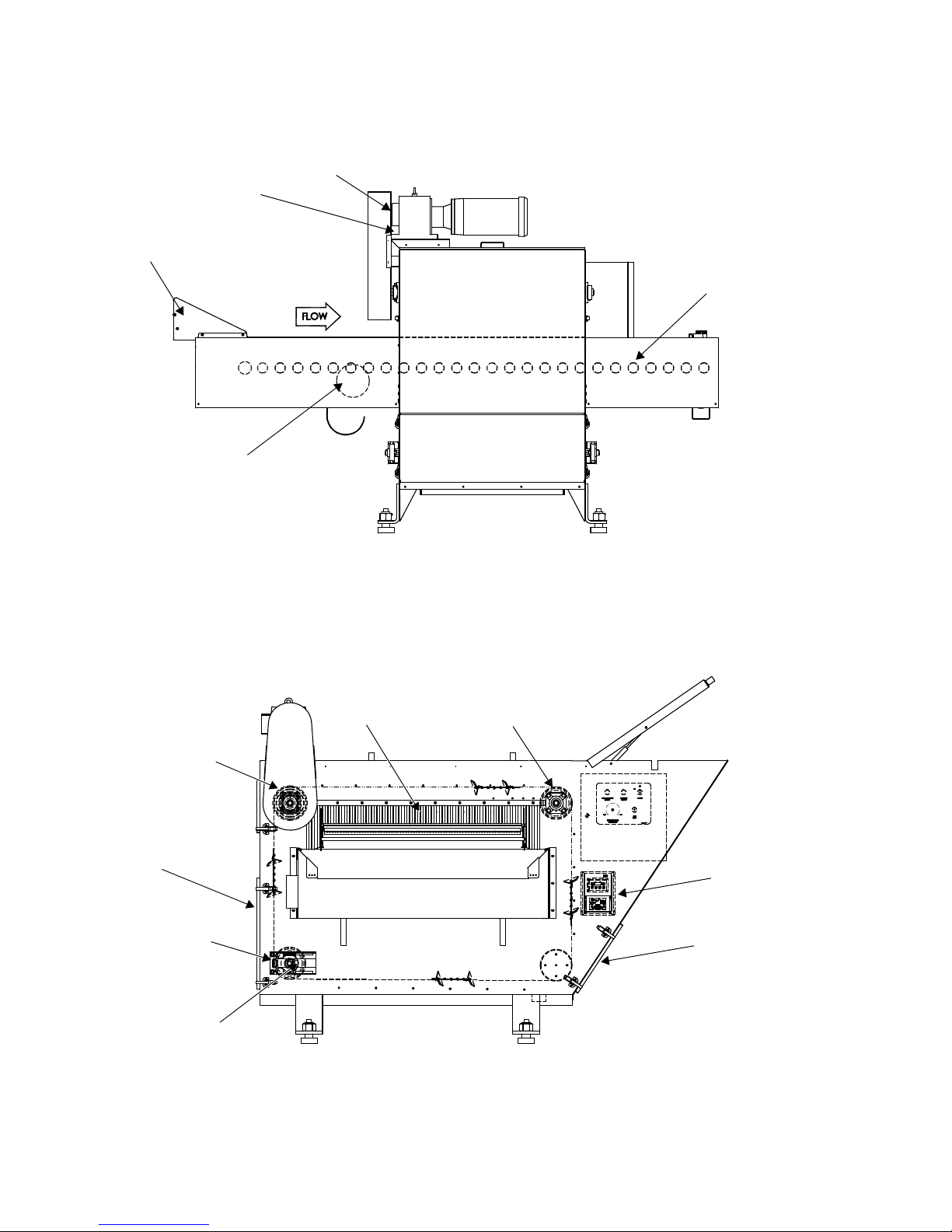
SIDE VIEW
FRONT VIEW
(Load Side)
Gearbox
Cage Flip-Over
System
Oil Level Plug
Conveyor Rollers
Ventilation System
Curtain
Conveyor Bearing
Conveyor Bearing
Service Access Panel
Conveyor Bearing
Take-Up Bearing
Cleanout Door
Figure 5-1. Cleaning and Maintenance
Drive
5-4
122996-163 Operator Manual Routine Maintenance
Page 21
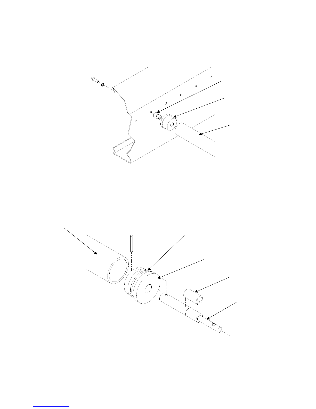
Figure 5-2. Removing Roller (Fixed End)
Short Axle
Roller End Cap
Roller
Figure 5-3. Removing Roller (Removable End)
Roller
O-Ring
End Cap
Holding Collar
Long Axle
Routine Maintenance Operator Manual 122996-163
5-5
Page 22
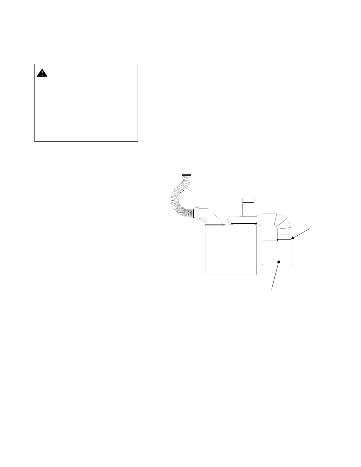
5.3.2 Empty Dust Collection
WARNING–ELECTRIC SHOCK
AND/OR BURN HAZARD:
Disconnect all utilities to dispenser before servicing. Do
not service dispenser unless
all utilities have been properly
locked out. Always follow local
lockout-tagout and electrical
safety-related work practice
standards.
Figure 5-4. Empty Dust Collection Bag
Dust Collection Bag
Bag
Clamp
System Bag
See Figure 5-4.
Empty dust collection bag as follows:
1. Lock electrical disconnect switch in OFF position.
2. Remove clamp holding dust collection bag in position.
3. Empty bag.
4. Reinstall bag using previously removed clamp.
5. Unlock electrical disconnect switch and position to ON.
5-6
122996-163 Operator Manual Routine Maintenance
Page 23

5.3.3 Clean Bedding
WARNING–ELECTRIC SHOCK
AND/OR BURN HAZARD:
Disconnect all utilities to dispenser before servicing. Do
not service dispenser unless
all utilities have been properly
locked out. Always follow local
lockout-tagout and electrical
safety-related work practice
standards.
CAUTION – POSSIBLE EQUIPMENT DAMAGE: Use nonabrasive cleaners when cleaning unit. Follow directions on
container and rub in a backand forth motion (in same
direction as surface grain).
Abrasive cleaners are harmful
to stainless steel.
Dispenser Exterior
STERIS recommends using the following cleaning products (refer to
Table 7-2 for ordering information):
• Pryde
TM
Multipurpose Cleaner – for routine cleaning and
polishing of unit.
• Pry Stain Remover Cream – for stubborn stains.
• Stainless-Steel Cleaner – for cleaning stainless-steel surfaces.
NOTE: To clean unit exterior, note the following:
1) Follow manufacturer's recommendations for proper product use
(concentrations, precautions to be taken, etc.) and read the Material Safety Data Sheet (MSDS) for safety information.
2) A lower service access panel is provided on the unload side of the
unit to ease cleaning of the dispenser portion of the unit.
At least once a week, clean unit exterior using a multipurpose cleaner
for general stains, a stainless-steel stain remover for stubborn stains
and a stainless-steel polish to keep equipment looking like new.
1. Lock electrical disconnect switch in OFF position.
2. Using a damp cloth or sponge, apply cleaner in a back-and-forth
motion, in same direction as surface grain.
3. Thoroughly wipe off cleaner.
4. Polish surface with a clean, dry, lint-free cloth.
NOTE: To ease cleaning of unit interior, a plugged cleanout drain
is provided, at bottom of dispenser.
5. Unlock electrical disconnect switch and position to ON.
Routine Maintenance Operator Manual 122996-163
5-7
Page 24
5.4 Weekly
WARNING–ELECTRIC SHOCK
AND/OR BURN HAZARD:
Disconnect all utilities to dispenser before servicing. Do
not service dispenser unless
all utilities have been properly
locked out. Always follow local
lockout-tagout and electrical
safety-related work practice
standards.
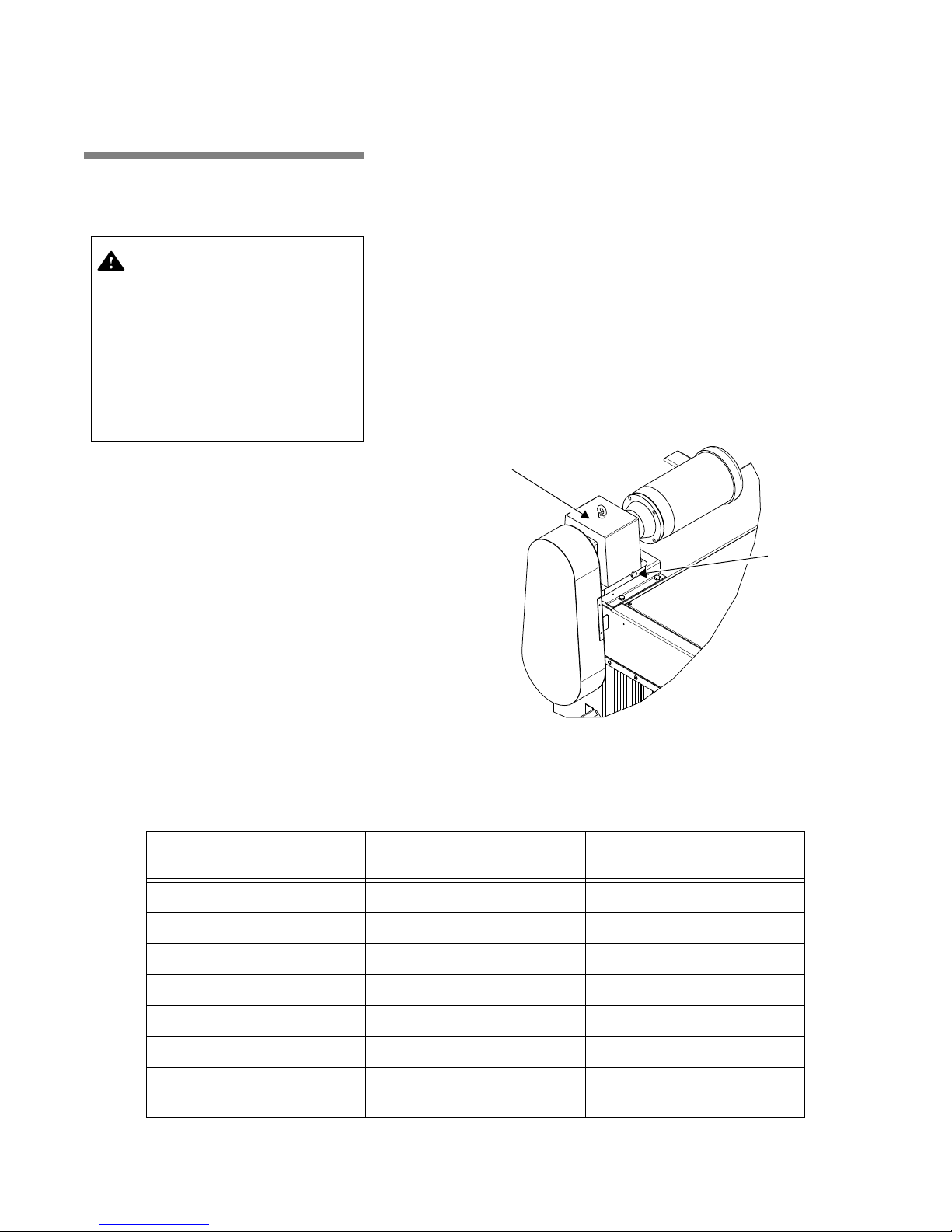
Oil Level Plug
Gearbox
Figure 5-5. Verify Gearbox Oil Level
Maintenance
5.4.1 Verify Gearbox Oil
Level
See Figures 5-1 and 5-5.
1. Lock electrical disconnect switch in OFF position.
2. Locate gearbox at top left side of unit, viewed from load side
(see Figure 5-1).
3. On right side of gearbox, loosen gearbox top oil level plug. Do
not remove plug (see Figure 5-5).
4. Oil should drip from hole. If not, add good quality gearbox oil as
necessary.
NOTE: See Table 5-2 for list of approved lubricants.
5. Retighten plug.
6. Unlock electrical disconnect switch and position to ON.
Table 5-2. Approved Lubricants For Gearboxes
Manufacturer Worm Gears
Chevron Oil Co. Cylinder Oil 460X NL Gear Compound #150
Exxon Oil Co. Cylesstic TK 460 Spartan EP 150
Gulf Oil Co. Transgear EP 460 EP Lubricant HO 150
Mobil Oil Co. 600 W Cylinder Oil Mobilgear 629
Shell Oil Co. Valvata J460 Omala 150
Sun Oil Co. Gear Oil 7C Suneo 1060
Texaco Inc.
5-8
122996-163 Operator Manual Routine Maintenance
AGMA #7 Compounded
Vanguard Cylinder
Oil 460
Spur, Bevel, Helical
AGMA #4 EP
Meropa 150
Page 25
5.4.2 Grease Cage Conveyor
WARNING–ELECTRIC SHOCK
AND/OR BURN HAZARD:
Disconnect all utilities to dispenser before servicing. Do
not service dispenser unless
all utilities have been properly
locked out. Always follow local
lockout-tagout and electrical
safety-related work practice
standards.
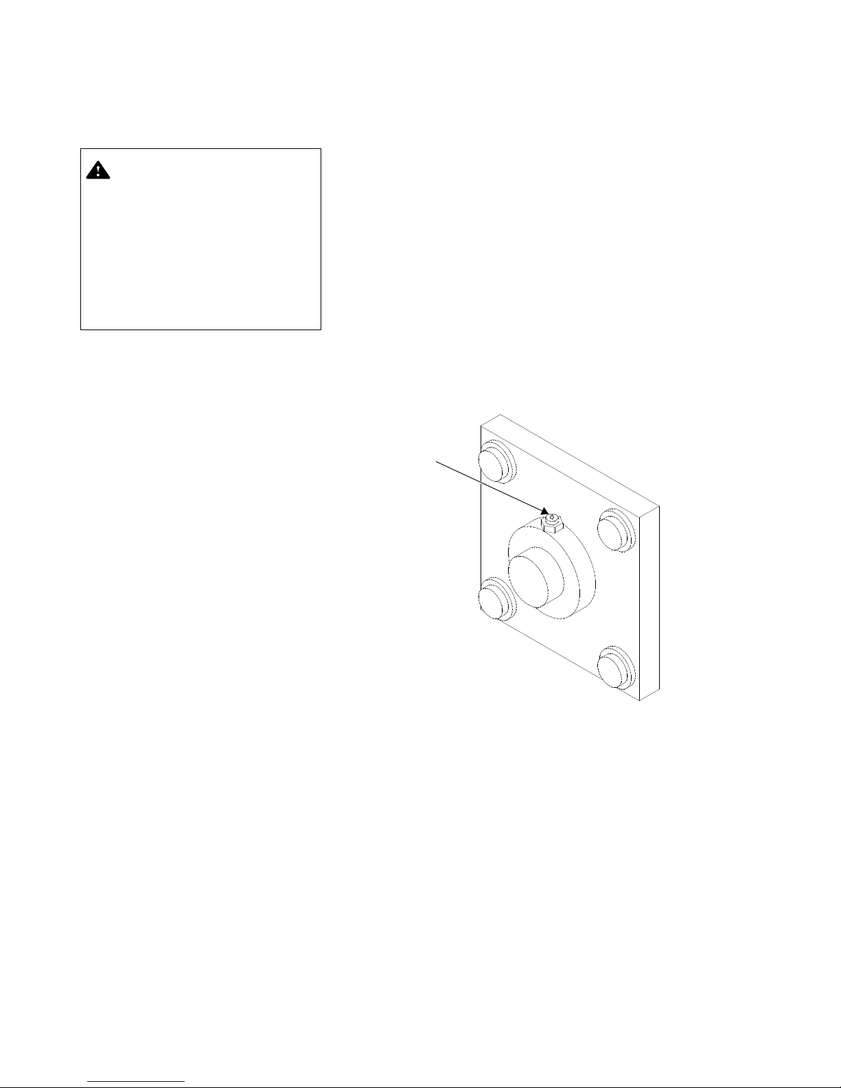
Figure 5-6. Grease Conveyor Bearings
Apply Grease
Bearings
See Figures 5-1 and 5-6.
Once a week, grease conveyor bearings as follows:
1. Lock electrical disconnect switch in OFF position.
2. Locate six conveyor bearing grease cups, three on each side of
unit (see Figure 5-1).
3. Apply two gun strokes of lithium-base grease to each bearing
cup (see Figure 5-6). Refer to S
PRODUCTS, for ordering information.
AND
ECTION 7, REPLACEMENT PARTS
4. Unlock electrical disconnect switch and position to ON.
Routine Maintenance Operator Manual 122996-163
5-9
Page 26
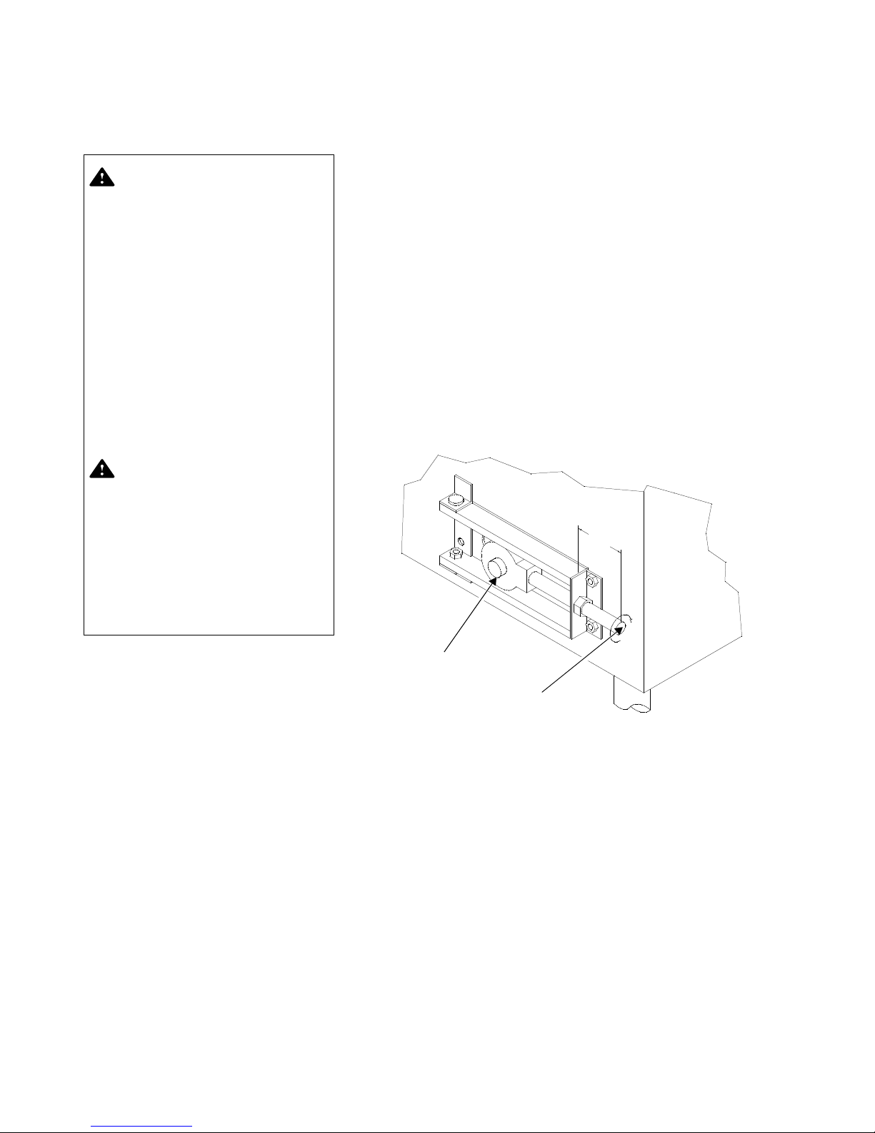
5.4.3 Adjust Dispenser Take-
WARNING–PERSONAL INJURY
AND/OR EQUIPMENT DAMAGE
HAZARD: Repairs and adjustments to this equipment must
be made only by STERIS or
STERIS-trained service personnel. Non-routine maintenance
performed by unqualified personnel or installation of unauthorized parts could cause
personal injury, result in
improper equipment performance, void the warranty or
result in costly damage. Contact STERIS regarding service
options.
WARNING–ELECTRIC SHOCK
AND/OR BURN HAZARD:
Disconnect all utilities to dispenser before servicing. Do
not service dispenser unless
all utilities have been properly
locked out. Always follow local
lockout-tagout and electrical
safety-related work practice
standards.
Figure 5-7. Adjust Dispenser Take-Up Bearings
Take-Up Bearing
Adjustment Rod
Up Bearings
See Figures 5-1 and 5-7.
1. Lock electrical disconnect switch in OFF position.
2. Locate dispenser take-up bearings (see Figure 5-1).
3. Adjust take-up bearings on dispenser belt, as needed, for tension and proper tracking. Turn clockwise to tighten, counterclockwise to loosen (see Figure 5-7).
4. Ensure adjustment distance is exactly the same on both sides of
dispenser belt. Do not overtighten.
5. Unlock electrical disconnect switch and position to ON.
5-10
122996-163 Operator Manual Routine Maintenance
Page 27
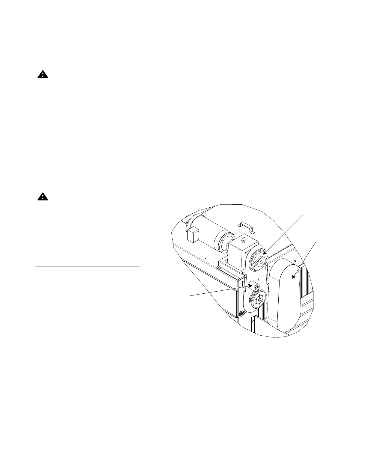
5.4.4 Adjust Dispenser
WARNING–PERSONAL INJURY
AND/OR EQUIPMENT DAMAGE
HAZARD: Repairs and adjustments to this equipment must
be made only by STERIS or
STERIS-trained service personnel. Non-routine maintenance
performed by unqualified personnel or installation of unauthorized parts could cause
personal injury, result in
improper equipment performance, void the warranty or
result in costly damage. Contact STERIS regarding service
options.
WARNING–ELECTRIC SHOCK
AND/OR BURN HAZARD:
Disconnect all utilities to dispenser before servicing. Do
not service dispenser unless
all utilities have been properly
locked out. Always follow local
lockout-tagout and electrical
safety-related work practice
standards.
Tensioner
Driving Chain
Cover
Torque Limiter
Figure 5-8. Adjust Dispenser Driving Chain
Tensioner
Driving Chain Tensioner
See Figure 5-8.
1. Lock electrical disconnect switch in OFF position.
2. Remove driving chain cover.
3. Adjust tensioner until there is no slack on chain as follows:
a. Using appropriate tools, loosen bolt inside tensioner while
holding nut located behind bolt.
b. Push on tensioner until there is no slack on chain.
c. Using appropriate tools, tighten bolt inside tensioner while
holding nut located behind bolt.
4. Reinstall driving chain cover.
5. Unlock electrical disconnect switch and position to ON.
Routine Maintenance Operator Manual 122996-163
5-11
Page 28
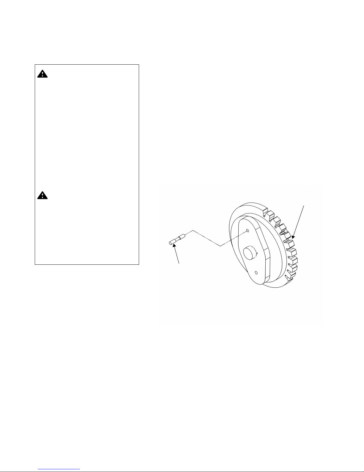
5.4.5 Replace Shear Pin on
WARNING–PERSONAL INJURY
AND/OR EQUIPMENT DAMAGE
HAZARD: Repairs and adjustments to this equipment must
be made only by STERIS or
STERIS-trained service personnel. Non-routine maintenance
performed by unqualified personnel or installation of unauthorized parts could cause
personal injury, result in
improper equipment performance, void the warranty or
result in costly damage. Contact STERIS regarding service
options.
WARNING–ELECTRIC SHOCK
AND/OR BURN HAZARD:
Disconnect all utilities to dispenser before servicing. Do
not service dispenser unless
all utilities have been properly
locked out. Always follow local
lockout-tagout and electrical
safety-related work practice
standards.
Figure 5-9. Replace Shear Pin on Torque Limiter
Shear Pin
Torque Limiter
Torque Limiter
See Figures 5-8 and 5-9.
1. Lock electrical disconnect switch in OFF position.
2. Remove driving chain cover (see Figure 5-8).
3. Remove broken shear pin parts from torque limiter and sprocket
using a suitable tool.
4. Align shear pin hole located in torque limiter with hole located in
sprocket.
5. Insert new shear pin inside hole using an Allen key.
6. Reinstall driving chain cover.
7. Unlock electrical disconnect switch and position to ON.
5-12
122996-163 Operator Manual Routine Maintenance
Page 29
6
TROUBLESHOOTING
WARNING–PERSONAL INJURY
AND/OR EQUIPMENT DAMAGE
HAZARD: Repairs and adjustments to this equipment must
be made only by STERIS or
STERIS-trained service personnel. Non-routine maintenance
performed by unqualified personnel or installation of unauthorized parts could cause
personal injury, result in
improper equipment performance, void the warranty or
result in costly damage. Contact STERIS regarding service
options.
WARNING–PERSONAL INJURY
HAZARD: Keep fingers and
hands away from chains,
gears or any other moving
parts. Also avoid wearing
loose clothing that could get
caught in mechanical parts.
WARNING–ELECTRIC SHOCK
AND/OR BURN HAZARD:
Disconnect all utilities to dispenser before servicing. Do
not service dispenser unless
all utilities have been properly
locked out. Always follow local
lockout-tagout and electrical
safety-related work practice
standards.
IMPORTANT: A listing of the Safety Precautions to be observed when operating and servicing this bedding
dispenser can be found in S
familiar with this information.
ECTION 1 of this manual. Do not operate the equipment until you have become
This section describes the types of Basil® 3600 Bedding Dispenser
malfunctions that can occur and indicates probable causes and corrective actions.
If you are unable to correct the problem using the Troubleshooting
Chart (see Table 6-1), or if a problem occurs that is not described in
the chart, please call STERIS. A factory-trained technician will
promptly place your bedding dispenser in proper working order.
NOTE: Never permit unqualified persons to service the bedding dispenser.
Troubleshooting Operator Manual 122996-163
6-1
Page 30

Table 6-1. Troubleshooting Chart
Problem Probable Cause/Corrective Action
1. Bedding dispenser or conveyor
not operating.
2. Dust coming out of bedding
dispenser.
1. Power ON/OFF selector switch positioned to OFF.
Position to ON (refer to S
ECTION 3.2.8).
2. Red Unit STOP pushbutton pressed. Pull out (refer to
S
ECTION 3.2.8).
3. Dispenser ON/OFF pushbutton positioned to OFF.
Position to ON (refer to S
ECTION 3.2.8).
4. Use bedding recommended by manufacturer.
5. Burned out fuse. Verify and replace if necessary.
6. Verify MSP1 is not tripped.
7. Wait two seconds after pulling Unit STOP pushbutton
before pushing Dispenser ON/OFF pushbutton to activate
bedding dispenser system. If there is no delay, push
Dispenser ON/OFF pushbutton to OFF position. Then,
push Dispenser ON/OFF pushbutton back to ON position.
8. Call STERIS.*
1. Dust Collector ON/OFF pushbutton positioned to OFF.
Position to ON (refer to S
ECTION 3.2.8).
2. Check dust collection system and empty bag if necessary
(refer to S
ECTION 5.3.2).
3. Verify MSP2 is not tripped.
3. Cage flip-over system does not
work properly.
1. Cage flip-over system must be installed as close as
possible and parallel to roller connectors to washer (if
connected to a Basil
®
6700 Tunnel Cage Washer). Adjust
cage flip-over system in correct position.
2. Incorrect height difference between top of tunnel cage
washer conveyor and top of Basil 3600 conveyor. Basil
3600 conveyor should be between 10-3/4 and 11" (273
and 279 mm) lower than tunnel cage washer conveyor.
4. Rollers falling in drip pan. Holding collar(s) missing. Reinstall holding collar on roller.
* Service charges may be incurred. Consult your warranty for details.
6-2
122996-163 Operator Manual Troubleshooting
Page 31

Table 6-1. Troubleshooting Chart (Cont’d)
Problem Probable Cause/Corrective Action
5. System operation very noisy. 1. Chain may be too slack. Verify chain slack and tighten if
necessary (refer to S
ECTION 5.4.4).
2. Lubricate sprockets and shaft with lithium-base grease
(P117951-457).
3. Chain gear may be worn out. Inspect gears for abnormal
wear. Change if necessary.
4. Gear setscrews may be loose. Tighten setscrews.
5. Sprocket shaft brass bushing may be worn out, causing
abnormal gear wear. Verify sprocket shaft bushing and
change if necessary.
6. Shear pin may be worn out. Inspect shear pin and change
if necessary (refer to S
ECTION 5.4.5).
Troubleshooting Operator Manual 122996-163
6-3
Page 32
7
REPLACEMENT PARTS AND PRODUCTS
WARNING–PERSONAL INJURY
AND/OR EQUIPMENT DAMAGE
HAZARD: Repairs and adjustments to this equipment must
be made only by STERIS or
STERIS-trained service personnel. Non-routine maintenance
performed by unqualified personnel or installation of unauthorized parts could cause
personal injury, result in
improper equipment performance, void the warranty or
result in costly damage. Contact STERIS regarding service
options.
WARNING–ELECTRIC SHOCK
AND/OR BURN HAZARD:
Disconnect all utilities to dispenser before servicing. Do
not service dispenser unless
all utilities have been properly
locked out. Always follow local
lockout-tagout and electrical
safety-related work practice
standards.
IMPORTANT: A listing of the Safety Precautions to be observed when operating and servicing this bedding
dispenser can be found in S
familiar with this information.
ECTION 1 of this manual. Do not operate the equipment until you have become
Use only STERIS authorized parts on this equipment. Use of unauthorized parts will void the warranty. To order replacement parts and/
or supply products, proceed as follows:
1. Include part number and description of equipment on your
order.
2. Include model and serial numbers of equipment on your order.
3. Send your order directly to STERIS.
Contact STERIS for service and if you need parts that are not listed
below. NEVER PERMIT UNQUALIFIED PERSONS TO SERVICE
THE BASIL
®
3600 BEDDING DISPENSER.
Table 7-1. Replacement Parts
Replacement Parts and Products Operator Manual 122996-163
Description Part Number
Common Parts
FUSE, 4 Amp, 250 V 117952-810
PHOTOELECTRIC Control 117943-163
POTENTIOMETER 117913-480
LED, Green, 120 V 117913-080
LED, Red, 120 V 117913-096
LED, White, 120 V 117913-091
CONTACTOR 117911-123
ROLLER, PVC, For 42" Conveyor 117913-105
COLLAR, Holding 117984-416
O-RING, Vitton, 1-5/8" OD x 1-7/16" ID 117913-044
208 Volts
STARTER, Manual, 4.5 - 6.3 Amp 117914-608
7-1
Page 33

Table 7-1. Replacement Parts (Cont’d)
Description Part Number
480 Volts
FUSE, 2.25 Amp 117913-048
STARTER, Manual, 2.2 - 3.2 Amp 117015-864
Cage Flip-Over System
CAP, Roller End Without Shoulder 117984-635
Driving Chain Torque Limiter
SHEAR, Pin 117913-522
Miscellaneous
GREASE (For Bearings) 117951-457
CYLINDER, Gas (Hopper Cover) 117916-309
CURTAIN, Plastic, 42" Conveyor 117007-347
BAG, Dust Collection System 117943-113
Transfer Plates
PLATE, Transfer, Curved 117052-757
PLATE, Transfer, Flat 117054-049
GUIDE, Fall, bedding 117052-750
Table 7-2. Cleaning Products
Description Quantity
TM
Pryde
Pry Stain Remover Cream
Stainless-Steel Cleaner
Multipurpose Cleaner
12 x16 oz
(475 mL)
6 x 32 oz
(950 mL)
12 X 12 oz
(340 g)
15 oz
(425 g)
Part
Number
NM829
NM830
NM430
NM410
7-2
122996-163 Operator Manual Replacement Parts and Products
 Loading...