

Page 1

BASEWEST
Operating & Calibration
Instructions
Model TS-453 Test Set
A380 Escape Slide
Lighting Systems
September 29, 2016
BASEWEST INC.
4240 116th Terrace N • Clearwater FL 33762
Tel: 727/573-2700 • Fax: 727/573-4307
E-mail: [email protected]
www.basewest.com
25-60-74
Page 2
BASEWEST
1.0 GENERAL
This manual covers the operation and calibration of the Model TS-453 Test Set for the
Airbus A380 escape slide lighting system. The Model TS-453 is designed to test for
short circuit conditions and/or electrical cross-talk in escape slide lighting circuits and
aircraft interface harnesses.
This device is a GO/NO-GO tester that does not provide parametric electrical readings.
Operating & Calibration Instructions
Model TS-453 Test Set
2.0 THEORY OF OPERATION
2.1 The Model TS-453 Test Set detects short circuits and/or electrical cross-talk conditions
in A380 escape slide lighting systems and electrical interface harnesses by verifying
each of the ten different circuits against all other circuits connected via the interface.
Testing is conducted relative to nominal threshold values of 2 M and 6.7K depending
on particular circuit at test. Circuit selection, sequencing, and testing are controlled by a
microprocessor in the device.
2.2 After proper hook-up and activation per the operating instructions, the TS-453 conducts
a self-test to confirm readiness for test. When the self-test is complete, testing of the
connected interface harness and systems will commence automatically. The test set
cycles automatically through each of the ten circuit tests (described in Appendix A),
illuminating each of the indicator LEDs, in order, left to right, top to bottom as the circuit
test is completed. The following indications are provided:
Page 2 of 12 25-60-74
29 September 2016
Page 3

BASEWEST
If all ten indicator LEDs in the top panel illuminate and remain ON, a proper
If all ten indicator LEDs in the top panel illuminate and remain GREEN, the
If one or more of the ten indicator LEDs in the top panel illuminates RED, the
2.4 Power is provided by a non-rechargeable 9V battery located in a compartment
accessible from the bottom of the instrument case. If the “LOW BATT” indicator light on
the main panel illuminates, the battery should be replaced before testing is conducted.
3.0 OPERATING INSTRUCTIONS
3.1 Connect the A380 interface harness and system to be tested to the TS-453 test set via
the 26-pin connector at the top of the instrument.
3.2 Slide the Door Test Selector switch to proper position for the interface harness under
test, as indicated:
Operating & Calibration Instructions
Model TS-453 Test Set
test has been accomplished. Otherwise, there is a fault in the instrument and
it must be checked and repaired before proceeding.
interface harness and attached system is “GO” and has tested good for
release to service.
interface harness and attached system is “NO GO” and may not be released
to service. The RED-illuminated indicator LED will indicate the particular
circuit that either a short circuit or cross-talk condition has been detected.
LEFT Position = M1, M2, M4, or M5 doors
RIGHT Position = M3 or Upper Deck (UD) doors
3.3 Turn the test set ON via the rocker switch on the instrument panel. All LEDs on the top
indicator light panel will activate and perform a self-test in the following sequence:
Three RED flashes with increasing intensity
Three GREEN flashes with increasing intensity
NOTE: if any LED fails to flash in this sequence, the test unit must be removed
from service and repaired prior to any testing.
3.4 Immediately after the self-test, the TS-453 will commence automatic testing of the
connected system via the interface harness. The progress of this test can be confirmed
by observing that each indicator LED turns ON, in sequence left to right, top to bottom,
as the individual circuits are tested. The LEDs remain ON until the test is complete and
the test set is turned OFF. The following are the test indications:
All LEDs illuminate GREEN and remain ON – This indicates that no short
circuit or cross-talk conditions have been detected in any of the circuits (e.g.,
there is an open circuit condition with a resistance of nominally 2 M and for
some special cases 6.7K), and that the interface harness under test is “GO”
and released for service.
One or more LEDs illuminate RED – This indicates that there is an electrical
closed/short circuit or cross-talk condition below the threshold resistance of
Page 3 of 12 25-60-74
29 September 2016
Page 4

BASEWEST
NOTE: Any deviation from these indications, including flickering of LED indicator
lights requires that the test set, the interface harness, and/or the connected
systems are suspected of a fault and must be checked and re-tested before
returned to service.
3.5 After the test is completed, turn the TS-453 OFF via the rocker switch. All LED’s will
revert to OFF, and the device is automatically re-set for the next test.
4.0 CALIBRATION PROCEDURE
4.1 Calibration may be performed by the user, a third party calibration facility, or BaseWest,
at the user’s option. Calibration is recommended to be performed on an annual basis,
but user experience and calibration requirements may indicate a different calibration
schedule.
Operating & Calibration Instructions
Model TS-453 Test Set
nominally 2 M or 6.7K in the circuit under test and the interface harness
and connected system under test is “NO GO” and may not be released to
service.
4.2 Remove all connections to the connector interface.
4.3 Turn the unit face down and remove the four screws attaching the back of the case.
Note: opening the unit will void any existing calibration.
4.4 Turn the unit face up and slightly separate the front of the case enough to have access
to Trimpot R1 located on the bottom left side of the main PCB which is attached to the
back cover.
4.5 Set the Door Test selector to M1,M2,M4,M5 and turn the unit on.
4.6 Allow the TS-453 to remain ON for at least 20 seconds after a test sequence has
completed. At that time, the test set will automatically cycle to a calibration mode. While
in this mode, the TS-453 can be calibrated in the following manner:
Connect an ammeter between Pins Y(-) and Z(+)
Read 2.40 +/- 0.05 A (microamps). If the reading is not in that range, Adjust
Trimpot R1 at Main PCB until reading is under limits.
4.7 Turn the unit OFF and turn back ON, allow the TS-453 to remain ON for at least 20
seconds after the test sequence has completed. At that time verify Ammeter reading of
2.40 +/- 0.05 uA between Pins Y(-) and Z(+).
4.8 Properly position the back and front of the case, close the unit and replace the four
screws. Note that attention should be taken not to pinch any internal wires or disconnect
the Ribbon cable.
Page 4 of 12 25-60-74
29 September 2016
Page 5
BASEWEST
Operating & Calibration Instructions
Model TS-453 Test Set
5.0 TEST SET GO/NO-GO CHECK HIGH RESISTANCE
5.1 The following GO/NO-GO check procedure can be performed on the TS-453, with
reference to Chart 1, below. This is the same procedure used for final inspection at the
factory. This check requires the BaseWest P/N 7-6045 test load.
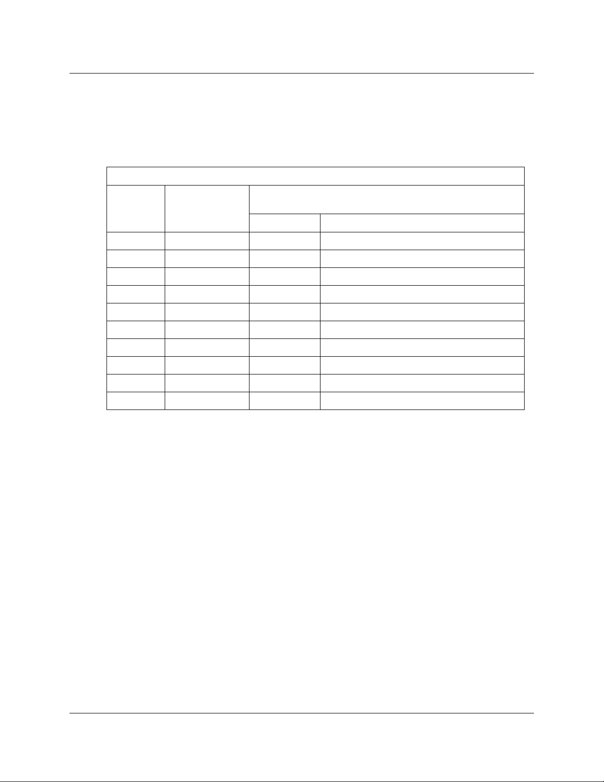
Chart 1 - TS-453 Test Set GO/NO-GO High Resistance Check
Circuit to
be Tested
MainGND M1, M2, M4, M5 X P,R,A,B,C,D,T,U,E,F,b,V,S,a,c,W
MainGND M3, UD G P,R,A,B,C,D,T,U,E,F,S,a,c,W
Lights M1, M2, M4, M5 M, K, or L P,R,A,B,C,D,T,U,E,F,b,V,S,a,c,W
CV M1, M2, M4, M5 P, R, A, or B M,L,K,J,G,H,C,D,T,U,E,F,b,V,S,a,c,W
RI M1, M2, M4, M5 J, or H P,R,A,B,C,D,T,U,E,F,b,V,S,a,c,W
GG M1, M2, M4, M5 C, D, T, or U M,L,K,J,G,H,P,R,A,B,E,F,b,V,S,a,c,W
SES M1, M2, M4, M5 E or F P,R,A,B,M,L,K,J,G,H,C,D,T,U,b,V,S,a,c,W
PGRV M1, M2, M4, M5 b or V P,R,A,B,M,L,K,J,G,H,C,D,T,U,E,F,S,a,c,W
CC M1, M2, M4, M5 S or a P,R,A,B,M,L,K,J,G,H,C,D,T,U,E,F,b,V,c,W
SDS M1, M2, M4, M5 c or W P,R,A,B,M,L,K,J,G,H,C,D,T,U,E,F,b,V,S,a
Door Selector
Test Switch
7-6045 Test Load: Install BLUE and WHITE Wire Pins
into the indicated TS-453 Connector Contact(s)
BLUE PIN WHITE PIN
5.2 With the unit turned OFF, place the Door Selector Test switch into the position indicated
for the circuit to be tested per Chart 1.
5.3 Place the BLUE wire pin contact on the 7-6045 test load into any of the TS-453
connector contacts listed under “BLUE Pin” in Chart 1 for the circuit to be tested.
5.4 Place the WHITE wire pin contact on the 7-6045 test load into any of the TS-453
connector contacts listed under “WHITE Pin” in Chart 1 for the circuit to be tested.
5.5 Select the “2.5 M (GREEN)” setting on the 7-6045.
5.6 Turn the TS-453 ON via the rocker switch. Wait for the unit to complete its automatic
self-test and circuit test procedures.
The LED indicator light for the circuit under test should illuminate GREEN, along
with all of the other indicator LEDs on the top panel.
5.7 Turn the TS-453 OFF via the rocker switch.
5.8 Select the “1.8 M (RED)” setting on the 7-6045.
Page 5 of 12 25-60-74
29 September 2016
Page 6
BASEWEST
Operating & Calibration Instructions
Model TS-453 Test Set
5.9 Turn the TS-453 ON again via the rocker switch. Wait for the unit to complete its
automatic self-test and circuit test procedures.
The LED indicator light for the circuit under test should illuminate RED; all other
indicator LEDs on the top panel should illuminate GREEN.
5.10 Repeat steps 5.2 through 5.9 for any number of combinations of circuits and/or pin-outs,
as required by the user use Appendix A for reference.
6.0 TEST SET GO/NO-GO CHECK LOW RESISTANCE
6.1 The following GO/NO-GO check procedure can be performed on the TS-453, with
reference to Chart 2, below. This check requires the two resistor loads of: a) 4.12 K
ohms for RED (NO-GO) and b) 28.0 K ohms for GREEN (GO) indication. (Resistor load
should be placed across test circuit contacts)
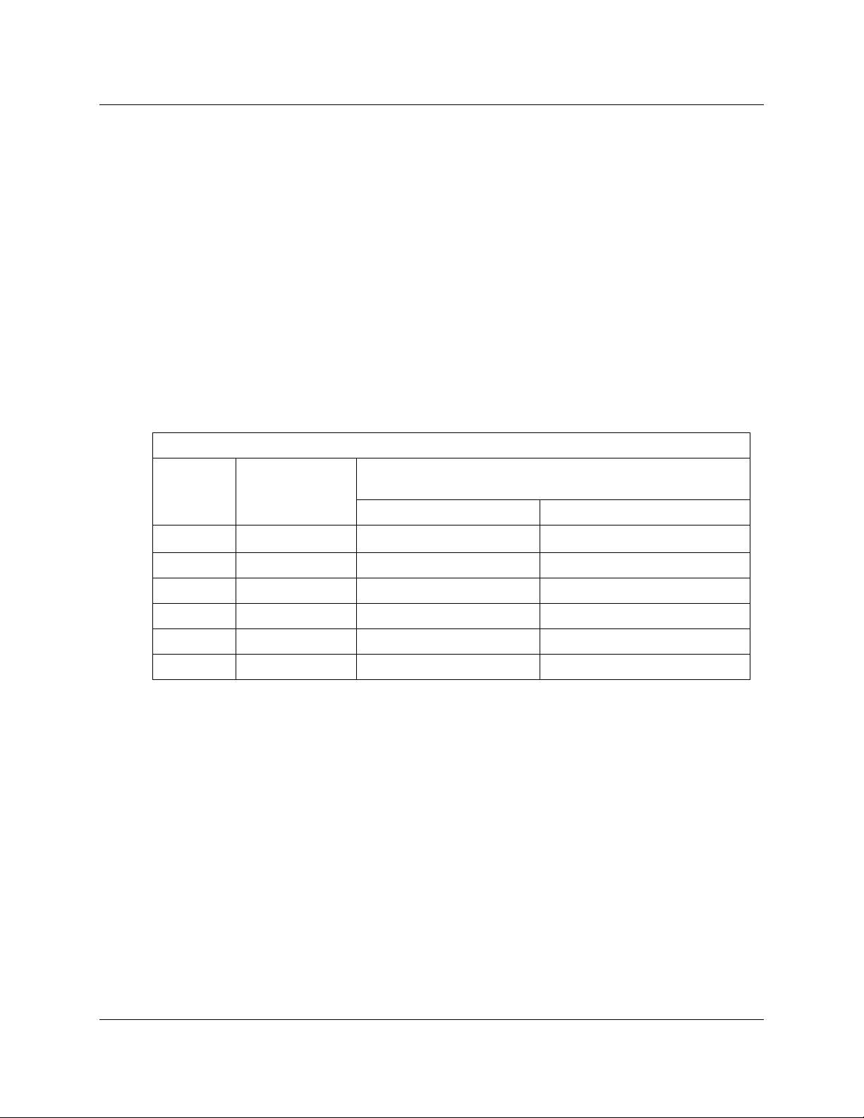
Chart 2 - TS-453 Test Set GO/NO-GO Low Resistance Check
Circuit to
be Tested
MainGND M1, M2, M4, M5 X M, or L
MainGND M3, UD G K, or L
Lights M1, M2, M4, M5 M, K, or L J, or H, or X
Lights M3, UD M, K, or L J, or H, or X
RI M1, M2, M4, M5 J, or H M, or K, or L
RI M3, UD J, or H M, or K, or L
Door Selector
Test Switch
7-6045 Test Load: Install BLUE and WHITE Wire Pins
into the indicated TS-453 Connector Contact(s)
BLUE PIN WHITE PIN
6.2 With the unit turned OFF, place the Door Selector Test switch into the position indicated
for the circuit to be tested per Chart 2.
6.3 Place the blue wire pin of the 7-6045 into any of the TS-453 connector contacts listed
under “BLUE PIN” in Chart 2 for the circuit to be tested.
6.4 Place the white wire pin of the 7-6045 into any of the TS-453 connector contacts listed
under “WHITE PIN” in Chart 2 for the circuit to be tested.
6.5 “GO” Check: Select the 28.0 K (GREEN) Load.
6.6 Turn the TS-453 ON via the rocker switch. Wait for the unit to complete its automatic
self-test and circuit test procedures.
The LED indicator light for the circuit under test should illuminate GREEN, along
with all off the other indicator LEDs on the top panel.
Page 6 of 12 25-60-74
29 September 2016
Page 7

BASEWEST
6.7 Turn the TS-453 OFF via the rocker switch.
6.8 “NO-GO” Check: Select the less than 4.12 K (RED) Load. Reconnect it to the same
contacts on the TS-453 that were previously selected in 6.3 and 6.4.
6.9 Turn the TS-453 ON again via the rocker switch. Wait for the unit to complete its
automatic self-test and circuit test procedures.
The LED indicator light for the circuit under test should illuminate RED; all other
indicator LEDs on the top panel should illuminate GREEN.
6.10 Repeat steps 6.2 through 6.9 for any number of combinations of circuits and/or pin-outs,
as required by the user, use Appendix A for reference.
7.0 CARE & MAINTENANCE
7.1 The TS-453 test set is a sensitive electronic instrument; it should be treated and
protected with appropriate care.
•
Do not drop or crush the instrument
Operating & Calibration Instructions
Model TS-453 Test Set
• Do not apply external electrical inputs
• Keep instrument away from all fluids
• Protect from extreme temperatures, weather/rain
7.2 The device is designed for handheld use in a shop environment and is not designed to
withstand a drop to the ground or to survive excessive compression loads.
7.3 The device is not water or fluid resistant; do not allow the device to sit in standing fluids or
subject to splash or rain.
7.4 Surface cleaning only with a slightly damped cloth (water or alcohol) is recommended.
DO NOT use other solvents or cleaners.
Page 7 of 12 25-60-74
29 September 2016
Page 8
BASEWEST
Operating & Calibration Instructions
Model TS-453 Test Set
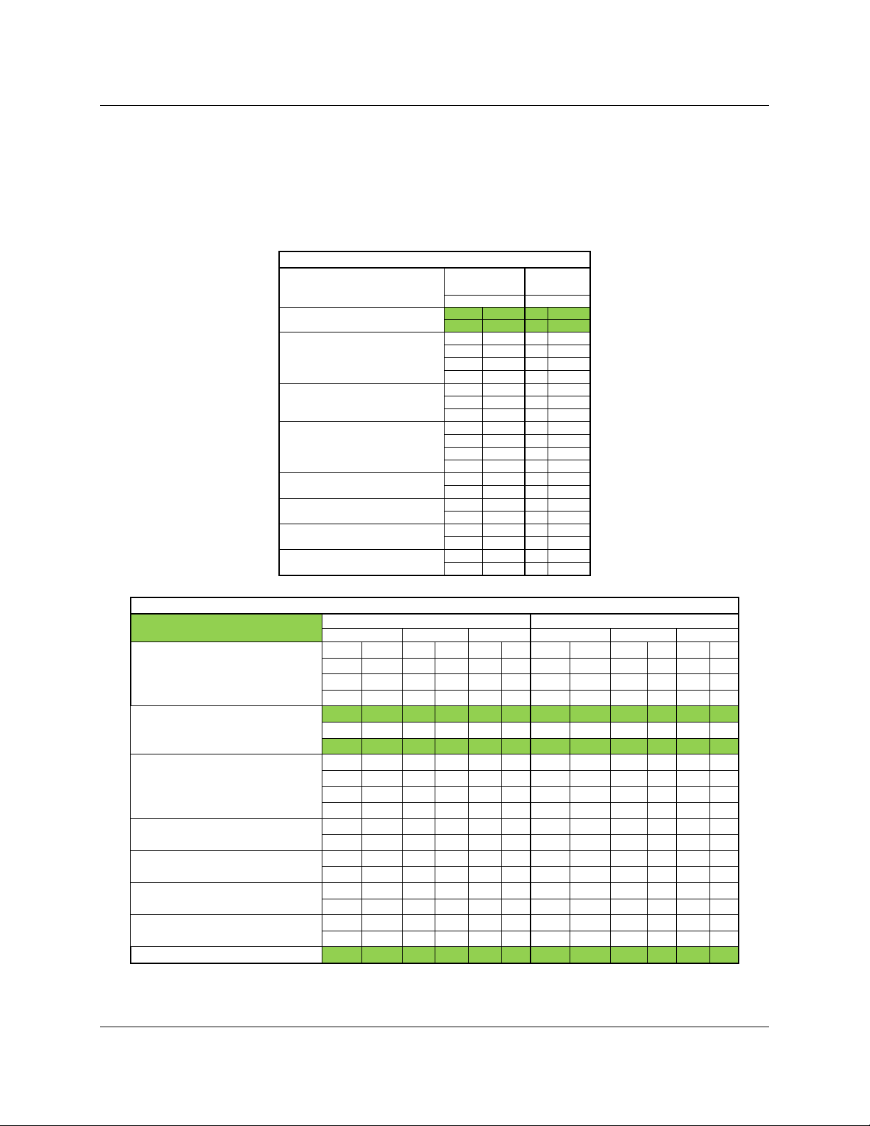
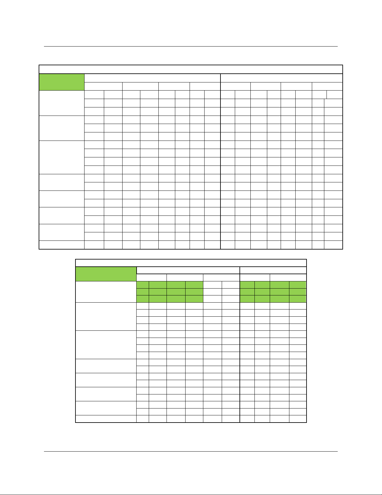
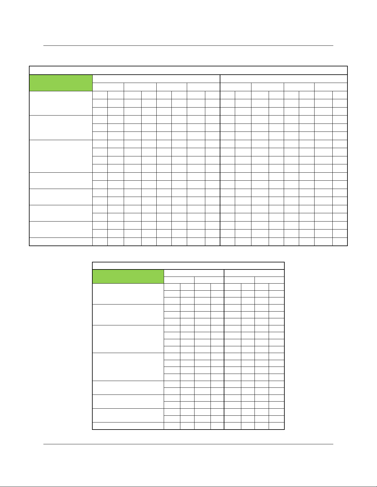
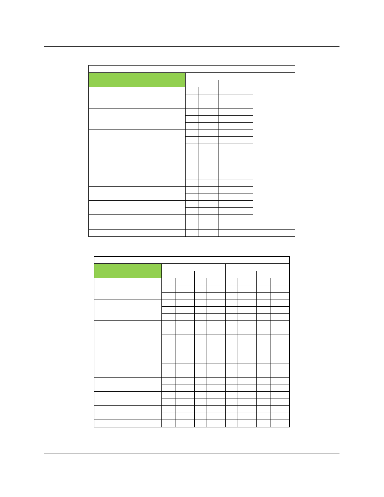
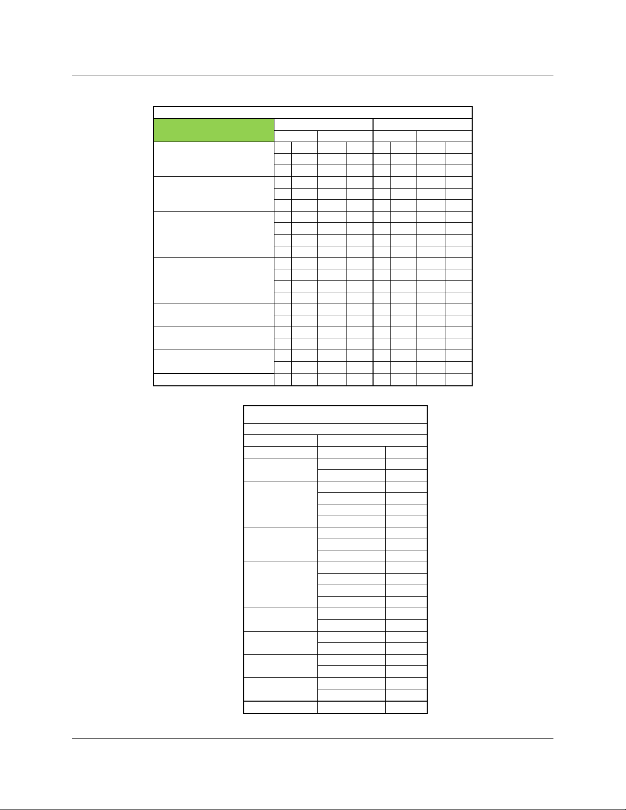
APPENDIX A – CIRCUIT TEST PROTOCOLS
The charts provided in this appendix detail the specific circuits that are tested during each automated test
cycle. This is provided as a reference only, but may be used to select specific circuits for the GO/NO-GO
check in Sections 5.0 and 6.0 (Highlighted cells are for 6.7K threshold see section 6.0 TEST SET
GO/NO-GO CHECK LOW RESISTANCE for details). If there are any questions, please contact
BaseWest.
Chart 2 - Main Ground Circuit Test
Lights
CV
RI
GG
SES
PGRV
CC
SDS
M1, M2, M4,
M5
vs vs
X M G K
X L G L
X P G P
X R G R
X A G A
X B G B
- - - -
- - - -
- - - X C G C
X D G D
X T G T
X U G U
X E G E
X F G F
X b - X V - X S G b
X a G V
X c G c
X W G W
M3, UD
Chart 3 - Lights Circuit Test
Lights Test
M P K P L P M P K P L P
CV
RI
GG
SES
PGRV
CC
SDS
Main GND M X K X L X - - K G L G
M R K R L R M R K R L R
M A K A L A M A K A L A
M B K B L B M B K B L B
M J K J L J M J K J L J
- - - - - - - - - - - M H K H L H M H K H L H
M C K C L C M C K C L C
M D K D L D M D K D L D
M T K T L T M T K T L T
M U K U L U M U K U L U
M E K E L E M E K E L E
M F K F L F M F K F L F
M b K b L b - - - - - M V K V L V - - - - - M S K S L S M b K b L b
M a K a L a M V K V L V
M c K c L c M c K c L c
M W K W L W M W K W L W
M1, M2, M4, M5 M3, UD
vs vs vs vs vs vs
Page 8 of 12 25-60-74
29 September 2016
Page 9
BASEWEST
Operating & Calibration Instructions
Model TS-453 Test Set
Chart 4 - CV Circuit Test
CV Test
Lights
RI
GG
SES
PGRV
CC
SDS
Main GND P X R X A X B X P G R G A G B G
vs vs vs vs vs vs vs vs
P M R M A M B M P M R M A M B M
P L R L A L B L P L R L A L B L
P K R K A K B K P K R K A K B K
P J R J A J B J P J R J A J B J
P G R G A G B G - - - - - - - -
P H R H A H B H P H R H A H B H
P C R C A C B C P C R C A C B C
P D R D A D B D P D R D A D B D
P T R T A T B T P T R T A T B T
P U R U A U B U P U R U A U B U
P E R E A E B E P E R E A E B E
P F R F A F B F P F R F A F B F
P b R b A b B b - - - - - - - -
P V R V A V B V - - - - - - - -
P S R S A S B S P b R b A b B b
P a R a A a B a P V R V A V B V
P c R c A c B c P c R c A c B c
P W R W A W B W P W R W A W B W
M1, M2,M3, M4, M5 UD M3, UD
Chart 5 - RI Circuit Test
RI Test
Lights
CV
GG
SES
PGRV
CC
SDS
Main GND - - - - - - - - - -
vs vs vs vs
J M H M - - J M H M
J K H K - - J K H K
J L H L - - J L H L
J P H P - - J P H P
J R H R - - J R H R
J A H A - - J A H A
J B H B - - J B H B
J C H C - - J C H C
J D H D - - J D H D
J T H T - - J T H T
J U H U - - J U H U
J E H E - - J E H E
J F H F - - J F H F
J b H b - - - - - J V H V - - - - - J S H S - - J b H b
J a H a - - J V H V
J c H c - - J c H c
J W H W - - J W H W
M1, M2, M4, M5 M3, UD
Page 9 of 12 25-60-74
29 September 2016
Page 10
BASEWEST
Operating & Calibration Instructions
Model TS-453 Test Set
Chart 6 - GG Circuit Test
GG Test
Lights
RI
CV
SES
PGRV
CC
SDS
Main GND C X D X T X U X C G R G T G U G
vs vs vs vs vs vs vs vs
C M D M T M U M C M D M T M U M
C L D L T L U L C L D L T L U L
C K D K T K U K C K D K T K U K
C J D J T J U J C J D J T J U J
C G D G T G U G - - - - - - - -
C H D H T H U H C H D H T H U H
C P D P T P U P C P D P T P U P
C R D R T R U R C R D R T R U R
C A D A T A U A C A D A T A U A
C B D B T B U B C B D B T B U B
C E D E T E U E C E D E T E U E
C F D F T F U F C F D F T F U F
C b D b T b U b - - - - - - - -
C V D V T V U V - - - - - - - -
C S D S T S U S C b D b T b U b
C a D a T a U a C V D V T V U V
C c D c T c U c C c D c T c U c
C W D W T W U W C W D W T W U W
M1, M2,M3, M4, M5 UD M3, UD
Chart 7 - SES Circuit Test
SES Test
Lights
RI
CV
GG
PGRV
CC
SDS
Main GND E X F X E G F G
M1, M2, M4, M5 M3, UD
vs vs vs vs
E M F M E M F M
E K F K E K F K
E L F L E L F L
E J F J E J F J
E G F G - - - E H F H E H F H
E P F P E P F P
E R F R E R F R
E A F A E A F A
E B F B E B F B
E C F C E C F C
E D F D E D F D
E T F T E T F T
E U F U E U F U
E b F b - - - E V F V - - - E S F S E b F b
E a F a E V F V
E c F c E c F c
E W F W E W F W
Page 10 of 12 25-60-74
29 September 2016
Page 11
BASEWEST
Operating & Calibration Instructions
Model TS-453 Test Set
Chart 8 - PGRV Circuit Test
PGRV Test
Lights
RI
CV
GG
SES
CC
SDS
MGND b X V X
Chart 9 - CC Circuit Test
CC Test
Lights
RI
CV
GG
SES
PGRV
SDS
MGND S X a X b G V G
M1, M2, M4, M5 M3, UD
vs vs vs vs
S M a M b M V M
S K a K b K V K
S L a L b L V L
S J a J b J V J
S G a G - - - S H a H b H V H
S P a P b P V P
S R a R b R V R
S A a A b A V A
S B a B b B V B
S C a C b C V C
S D a D b D V D
S T a T b T V T
S U a U b U V U
S E a E b E V E
S F a F b F V F
S b a b - - - S V a V - - - S c a c b c V c
S W a W b W V W
M1, M2, M4, M5 M3, UD
vs vs
b M V M
b K V K
b L V L
b J V J
b G V G
b H V H
b P V P
b R V R
b A V A
b B V B
b C V C
b D V D
b T V T
b U V U
b E V E
b F V F
b S V S
b a V a
b c V c
b W V W
In this mode
PGRV indicator
is set by default
to GREEN
since in M3/UD
mode there are
no pins
assigned for a
pin by pin
verification.
Page 11 of 12 25-60-74
29 September 2016
Page 12
BASEWEST
Operating & Calibration Instructions
Model TS-453 Test Set
Chart 10 - SDS Circuit Test
SDS Test
Lights
RI
CV
GG
SES
PGRV
CC
MGND c X W X c G W G
M1, M2, M4, M5 M3, UD
vs vs vs vs
c M W M c M W M
c K W K c K W K
c L W L c L W L
c J W J c J W J
c G W G - - - c H W H c H W H
c P W P c P W P
c R W R c R W R
c A W A c A W A
c B W B c B W B
c C W C c C W C
c D W D c D W D
c T W T c T W T
c U W U c U W U
c E W E c E W E
c F W F c F W F
c b W b - - - c V W V - - - c S W S c b W b
c a W a c V W V
Chart 11 - Case Ground Circuit Test
M1, M2, M3, M4, M5, UD
Circuits
Case GND vs k
Lights
CV
RI
GG
SES
PGRV
CC
SDS
Case GND vs X Case GND X
Case GND K
Case GND M
Case GND L
Case GND P
Case GND R
Case GND A
Case GND B
Case GND J
Case GND G
Case GND H
Case GND C
Case GND D
Case GND T
Case GND U
Case GND E
Case GND F
Case GND b
Case GND V
Case GND S
Case GND a
Case GND c
Case GND W
vs
Page 12 of 12 25-60-74
29 September 2016
 Loading...