


 Loading...
BaseStation 3200
Advanced Irrigation Controller
User Manual
Firmware Version 12.9
July 11, 2013
Contents at a Glance
Section 1 |
Introduction |
Section 2 |
System Components |
Section 3 |
Wiring Guidelines |
Section 4 |
BaseStation 3200 Interface |
Section 5 |
Configuring Devices |
Section 6 |
Initial Programming |
Section 7 |
Flow Management & Monitoring |
Section 8 |
Manual Operations |
Section 9 |
System Management |
Section 10 |
Reports, Messages, & Logs |
Section 11 |
Troubleshooting |
Section 12 |
Appendix |
Customer Service 1-866-294-5847
Baseline Inc. www.baselinesystems.com
Phone 208-323-1634
FAX 208-323-1834
Toll Free 866-294-5847
©2013 Baseline Inc. All Rights Reserved.
Revision 2

Table of Contents |
|
1 – INTRODUCTION................................................................................................................................. |
1 |
How to Read this Manual.................................................................................................... |
1 |
How to Irrigate Efficiently ................................................................................................... |
1 |
Soil Moisture Content......................................................................................................... |
2 |
How to Use Soil Moisture Sensors Successfully ................................................................... |
4 |
Choosing the Primary Zone for a Scheduling Group............................................................ |
5 |
Choosing the Sensor Location ............................................................................................. |
5 |
Dealing with Slopes and Berms...................................................................................... |
5 |
Optimal biSensor Placement for Slopes and Berms....................................................... |
6 |
Burying the biSensor ........................................................................................................... |
6 |
Turf Grass ...................................................................................................................... |
6 |
Newly Seeded Turf Grass or New Sod............................................................................ |
6 |
Trees and Shrubs ........................................................................................................... |
7 |
Installing biSensors with New Trees .............................................................................. |
8 |
Shrubs and Other Ornamental Plants ............................................................................ |
8 |
Gardens and Crop Plants ............................................................................................... |
8 |
Watering Strategies ............................................................................................................ |
8 |
Root Depth and Plant Water Efficiency ............................................................................... |
9 |
Understanding Soak Cycling.............................................................................................. |
10 |
Precipitation Rates vs. Infiltration Rates ........................................................................... |
10 |
Precipitation Rates for Common Sprinkler Types ........................................................ |
10 |
Estimated Infiltration Rates for Common Soil Types.................................................... |
10 |
Using Soak Cycles with Soil Moisture Sensors................................................................... |
11 |
Distribution Uniformity..................................................................................................... |
12 |
2 – SYSTEM COMPONENTS................................................................................................................. |
13 |
Cabinet Options................................................................................................................ |
13 |
Central Control and Remote Communication Options ....................................................... |
14 |
Remote Communication Options...................................................................................... |
14 |
LiveView™ ......................................................................................................................... |
14 |
BaseManager™ 2.0............................................................................................................ |
14 |
BL Commander.................................................................................................................. |
15 |
Two-Wire Devices............................................................................................................. |
15 |
Total Supported Devices and Limits .................................................................................. |
16 |
Maximum Concurrent Valves....................................................................................... |
17 |
Maximum Wire Distances for 3200R and 5200R Series biCoders ................................ |
17 |
3 – WIRING GUIDELINES..................................................................................................................... |
18 |
Conventional Irrigation Wiring Installation........................................................................ |
18 |
Conventional Wiring Modules........................................................................................... |
18 |
Connecting Valve Wires and Moisture Sensors over Valve Wires ..................................... |
19 |
BL-5200 Series Powered biCoder Wiring Example with One biSensor ......................... |
19 |
Expanding with Two-Wire................................................................................................. |
20 |
Connecting to BL-5200R Series Wall Mount biCoders....................................................... |
21 |
Example Wiring Diagram ............................................................................................. |
21 |
Two-Wire Installation ....................................................................................................... |
22 |
Two-Wire Serial Numbers ................................................................................................. |
22 |
Two-Wire Connections and Layout ................................................................................... |
22 |
Wire Connections ........................................................................................................ |
22 |
Wire Lengths................................................................................................................ |
23 |
|
Page i |

Wire Layout ................................................................................................................. |
23 |
Wire Burial................................................................................................................... |
24 |
Removing a Two-Wire Device ........................................................................................... |
24 |
4 – THE BASESTATION 3200 INTERFACE ...................................................................................... |
25 |
Controller Front Panel Layout ........................................................................................... |
25 |
Online Help ...................................................................................................................... |
26 |
RUN Main Screen.............................................................................................................. |
26 |
Status Colors .................................................................................................................... |
27 |
On-Screen Reports............................................................................................................ |
27 |
Power Cycling or Restarting the Controller........................................................................ |
27 |
Setting the Controller Time and Date ................................................................................ |
28 |
Checking the Firmware Version on Your Controller ........................................................... |
28 |
5 – CONFIGURING DEVICES................................................................................................................ |
29 |
Searching For and Configuring Zone biCoders.................................................................... |
29 |
Searching For biCoders (including Powered biCoders)...................................................... |
29 |
Assigning Valve biCoders to Zone Numbers...................................................................... |
30 |
Zone Numbers are Pre-Assigned in R-Series ................................................................ |
30 |
To assign biCoders to zones......................................................................................... |
30 |
To clear a previous zone number assignment.............................................................. |
31 |
Configuring Zone Settings ................................................................................................. |
31 |
Adjusting the Valve Power Level for a biCoder ................................................................. |
33 |
Searching For Start, Stop, & Pause Devices........................................................................ |
34 |
Searching For and Assigning Event biCoders..................................................................... |
34 |
Searching For and Assigning Soil Moisture Sensors (for Start, Stop, Pause Conditions).... |
35 |
Searching For and Assigning Air Temperature Sensors ..................................................... |
35 |
Searching For and Assigning Other Devices ....................................................................... |
36 |
Searching For and Assigning biSensors ............................................................................. |
36 |
Searching For and Assigning Pump Start Devices and Master Valves................................ |
37 |
Searching For and Assigning Flow Meters......................................................................... |
38 |
6 – INITIAL PROGRAMMING .............................................................................................................. |
39 |
Setting Up Time-Based Watering ...................................................................................... |
39 |
Setting Up a Timed Zone................................................................................................... |
39 |
To set up a timed zone................................................................................................. |
39 |
Setting Up a Primary Zone ................................................................................................ |
41 |
Prerequisites................................................................................................................ |
41 |
To assign a primary zone ............................................................................................. |
41 |
Linking Zones (Creating a Scheduling Group).................................................................... |
42 |
Adjusting the Water Time Tracking Ratio of Linked Zones................................................ |
43 |
Using Soak Cycles ............................................................................................................. |
44 |
To set up soak cycles for a zone ........................................................................................ |
44 |
To disable soak cycles ....................................................................................................... |
45 |
Setting Up Programs......................................................................................................... |
46 |
To set up the start times for a program ............................................................................ |
46 |
To set up the start days for a program.............................................................................. |
47 |
To set up program start days based on a historical calendar ............................................ |
48 |
Prerequisites................................................................................................................ |
48 |
Instructions.................................................................................................................. |
49 |
To set up the water windows for a program..................................................................... |
49 |
To set up concurrent zones for a program........................................................................ |
51 |
To set the priority for a program....................................................................................... |
52 |
To adjust programs for seasonal variations ...................................................................... |
52 |
Page ii |
|

Associating Zones with a Program..................................................................................... |
53 |
Removing a Zone from a Program ..................................................................................... |
54 |
Setting Up Soil Moisture Sensor Based Watering............................................................... |
54 |
Prerequisites for Watering with Soil Moisture Sensors..................................................... |
55 |
To configure your biSensors and set up watering strategies............................................. |
55 |
Understanding Lower & Upper Limit Watering Strategies.................................................. |
56 |
Lower Limit ....................................................................................................................... |
56 |
Upper Limit ....................................................................................................................... |
57 |
Complying with Water Restrictions ................................................................................... |
58 |
Setting Up Start, Stop, and Pause Conditions .................................................................... |
59 |
To set up start, stop, pause conditions for event switches ............................................... |
59 |
To set up start, stop, pause conditions for soil moisture sensors ..................................... |
60 |
To set up start, stop, pause conditions for air temperature sensors................................. |
61 |
Setting Up Event Days....................................................................................................... |
62 |
7 – FLOW MANAGEMENT & MONITORING..................................................................................... |
63 |
Assigning Devices to Water Sources .................................................................................. |
63 |
Setting Up a Water Source................................................................................................ |
64 |
To set up the water source ............................................................................................... |
65 |
Setting Up Empty Conditions for a POC ............................................................................. |
66 |
Setting Up a Booster Pump for a Program ......................................................................... |
66 |
Assigning Water Sources to Mainlines............................................................................... |
67 |
Assigning Programs to Mainlines ...................................................................................... |
68 |
Setting Up the Mainline Operating Limits.......................................................................... |
68 |
To set up the mainline ...................................................................................................... |
70 |
Learning Flow ................................................................................................................... |
71 |
Learning the Flow by Zone ................................................................................................ |
71 |
Learning the Flow by Program .......................................................................................... |
72 |
Managing Multiple Flow Devices and Mainlines................................................................ |
72 |
8 – MANUAL OPERATIONS ................................................................................................................. |
74 |
Forcing a Program to Start ................................................................................................ |
74 |
Stopping an Active Program.............................................................................................. |
75 |
Manually Starting/Stopping the Zones of a Program ......................................................... |
75 |
Manually Running One or All Zones for a Fixed Time......................................................... |
76 |
Manually Running Zones for a Fixed Time ......................................................................... |
77 |
Manually Running Programs for a Fixed Time.................................................................... |
78 |
Manually Running a Pump or MV for a Fixed Time ............................................................ |
78 |
Setting the System to OFF................................................................................................. |
79 |
9 – SYSTEM MANAGEMENT................................................................................................................ |
80 |
Selecting the Language for Online Help ............................................................................. |
80 |
Setting Up Security for the Controller................................................................................ |
80 |
Setting the Two-Wire to Always On .................................................................................. |
81 |
Changing the Serial Number of Your Controller ................................................................. |
81 |
Using the USB Data Functions ........................................................................................... |
82 |
Backing Up Your System.................................................................................................... |
82 |
Restoring Your System ...................................................................................................... |
83 |
Exporting Log Files ............................................................................................................ |
83 |
Erasing All Programming from the Controller .................................................................... |
84 |
Erasing All Files from the Controller .................................................................................. |
85 |
Updating the Controller Firmware .................................................................................... |
85 |
To update the controller’s firmware from the Baseline web site with a USB drive........... |
86 |
|
Page iii |

To update the controller’s firmware from BaseManager.................................................. |
87 |
Connecting to BaseManager – Overview ........................................................................... |
87 |
Enabling the BaseManager Connection on the Controller ................................................ |
88 |
Checking the Status of the BaseManager Connection ...................................................... |
88 |
Activating Your BaseManager Account ............................................................................. |
89 |
Getting More Information about BaseManager................................................................ |
89 |
Setting Up the Default Network Connection...................................................................... |
89 |
Setting Up a Static IP Address ........................................................................................... |
90 |
Understanding the Ethernet Settings ................................................................................ |
91 |
Enabling a Cell Modem Connection................................................................................... |
91 |
10 – REPORTS, MESSAGES, & LOGS.................................................................................................. |
92 |
Zone Status ...................................................................................................................... |
92 |
Status Colors .................................................................................................................... |
93 |
Test All Report.................................................................................................................. |
94 |
Moisture Sensor Data ....................................................................................................... |
94 |
To display the Soil Moisture Sensor Data report............................................................... |
94 |
Program Run Time Report................................................................................................. |
95 |
To display the Program Run Time report .......................................................................... |
95 |
Water Used ...................................................................................................................... |
95 |
To display the Water Used report ..................................................................................... |
95 |
Operator Messages........................................................................................................... |
96 |
To display the messages.................................................................................................... |
96 |
Pause Messages................................................................................................................ |
96 |
11 – TROUBLESHOOTING................................................................................................................... |
99 |
Testing a Specific Two-wire Device.................................................................................... |
99 |
Possible Statuses for Valve biCoders................................................................................. |
99 |
Possible Statuses for Soil Moisture Sensors (biSensors) ................................................. |
100 |
Checking and Repairing Two-wire Device Assignments and Addresses.............................. |
101 |
Testing All Devices........................................................................................................... |
102 |
Performing a Two-wire Blink Test .................................................................................... |
102 |
Troubleshooting the Two-Wire: High Current or Shorted.................................................. |
103 |
Diagnosing a Circuit Board Issue ..................................................................................... |
104 |
Troubleshooting with a Milliamp Clamp Meter .............................................................. |
104 |
Troubleshooting Manually .............................................................................................. |
105 |
Troubleshooting: Lost Devices | No Response .................................................................. |
105 |
12 – APPENDIX.................................................................................................................................... |
106 |
Warranty......................................................................................................................... |
106 |
Tips for Setting Up Common Configurations..................................................................... |
107 |
Lower Threshold Moisture Sensor Based Watering ........................................................ |
107 |
Upper Threshold Moisture Sensor Based Watering ........................................................ |
107 |
BL-3200-R Hydrozone Worksheet..................................................................................... |
109 |
Existing Irrigation Controller Information ....................................................................... |
109 |
Additional Information for Existing Programs................................................................. |
110 |
Programming Information for the BaseStation 3200 Controller ..................................... |
110 |
Additional Information for New Programs...................................................................... |
112 |
Glossary of Terms ............................................................................................................ |
113 |
Page iv

BaseStation 3200 Advanced Irrigation Controller Manual
1 – Introduction
Congratulations on choosing the most capable commercial grade smart irrigation controller in the world! You will find that the BaseStation 3200 is capable of dramatically reducing your water use while improving the health and quality of your landscape. Fully central control compatible, the BaseStation 3200 controller will typically pay for itself in one to two seasons based on water waste reduction alone.
The BaseStation 3200 is specifically designed to help you irrigate more efficiently than any other commercial irrigation controller. The 3200 supports multiple smart watering strategies, including smart watering with soil moisture sensors and a historical ET calendar.
At Baseline, our mission is to forever change the way people water plants by providing the smartest, easiest and most capable irrigation control products ever made. If you have feedback on how we can make our products better, please do not hesitate to contact us.
IMPORTANT NOTE! Install all electrical components including the BaseStation controller in compliance with local electrical and building codes.
How to Read this Manual
For first time users, sections 1 through 6 provide an overview of how to get your new BaseStation 3200 controller up and running quickly, while sections 7 through 12 provide information on advanced functions and troubleshooting.
For additional information, you can also visit the Baseline web site at
http://www.baselinesystems.com
To get the most out of your BaseStation 3200, we recommend that you review the information in this Introduction before you install and configure your system.
How to Irrigate Efficiently
This section covers some key concepts that are essential to better and more efficient irrigation. When you irrigate properly, you will reduce or eliminate water waste and improve the health of your plants.
All other considerations being equal, you will see better watering results with soil moisture sensors than with any other currently available technology. When you set up your BaseStation 3200 to water based on soil moisture sensor data, your system becomes a “closed loop” – in other words, the soil moisture sensor directly measures the moisture in the root zone, and the controller adjusts watering to maintain the desired moisture levels.
•Water deeply and infrequently. Studies show that watering deeply and infrequently promotes deeper root growth and more drought tolerant plants.
Page 1

BaseStation 3200 Advanced Irrigation Controller Manual
Watering deeply means that the soil should be wetted down to a depth of 6 inches or deeper for grasses and 12 inches or deeper for trees and shrubs.
Watering infrequently means that the next irrigation event (or start time) should be delayed as long as possible without stressing the plants.
•Deeper roots = more efficient plants. Plants with deeper roots are able to draw more nutrients from a larger area of soil, making fertilizers and soil treatments more effective.
•Avoid runoff. Matching the application rate of irrigation to the infiltration rate of the soil is critical to avoid runoff.
•Only apply the amount of water needed. Irrigation water is a supplement to natural rainfall – you only need to apply the amount of water needed to return the soil to optimum moisture.
Irrigation water applied above the field capacity of the soil is wasted – water will gravitationally sink through the soil below the root zone of the plants.
Unlike other irrigation controllers, the 3200 is specifically designed to make efficient irrigation easy. Before you start setting up and programming your BaseStation 3200, it is helpful to understand the following concepts:
•Soil Moisture Content
•How to Use Soil Moisture Sensors, including:
Hydrozones
Scheduling groups
Primary zones and linked zones
•Watering Strategies
•Root Depth and Plant Water Efficiency
•Soak Cycling
•Distribution Uniformity
The remainder of this section covers these key concepts in more detail.
Soil Moisture Content
Soil scientists and agronomists have been studying the plant-water-soil system for over 100 years. Early work in irrigation efficiency focused on the estimation of soil moisture based on weather information, plant water requirements, and soil information such as soil texture and slope. With the availability of inexpensive and highly accurate soil moisture sensors, we are able to take soil moisture based irrigation to a whole new level of efficiency and effectiveness.
With soil moisture sensors, your controller can operate like a thermostat for your landscape – applying water when it is needed, and where it is needed.
Page 2
BaseStation 3200 Advanced Irrigation Controller Manual
To understand soil moisture based smart irrigation, you also need to understand the following industry standard terms for soil moisture content.
Wetter
Saturation |
The soil pores are filled with water and nearly all of the air in the |
|
soil has been displaced by water. Gravity exerts force on the |
|
water contained in saturated soils, moving it deeper into the |
|
ground (if possible). When this “gravitational water” moves |
|
down through the soil, it becomes unavailable to plants. |
Field Capacity |
The level of soil moisture left in the soil after drainage of the |
|
gravitational water. If you irrigate to a level above field capacity, |
|
it will result in runoff or drainage as gravitational water. |
Drier
Maximum |
When the soil moisture content reaches this level, irrigation |
Allowed |
needs to start. In most cases, the maximum allowed depletion |
Depletion |
level is well before the plants begin to show visible signs of |
(MAD) |
stress. Irrigators typically start watering at or before MAD is |
|
reached because they do not want their landscapes to show |
|
signs of stress. |
Permanent |
The minimal point of soil moisture where the plants wilt and |
Wilt Point |
begin to die off. |
Oven Dry |
When soil is dried in an oven, nearly all water is removed. This |
|
moisture content is used to provide a reference for measuring |
|
saturation, field capacity, and MAD. |
One key point is that water applied above field capacity is generally wasted – it gravitationally moves down through the soil and becomes unavailable to plants. Excess water will also leech nutrients from the soil into deeper soil layers, reducing the efficiency of fertilizers and soil treatments.
To understand field capacity, it is often useful to think of a sponge. If you dunk a sponge in a bucket of water and pull it out, water will gravimetrically drain from the sponge for a period of time. When the dripping stops, the sponge will still be very wet. This moisture level is roughly equivalent to field capacity in soils – water is no longer draining into lower soil layers and is held in the root zone of the plants.
When your irrigation system maintains soil moisture content between field capacity and maximum allowed depletion, you will find that your plants are healthier and your water use actually decreases. Studies also show that appropriately varying the time between irrigation events in order to allow the soil to dry to the chosen depletion point promotes deeper root growth and subsequently more efficiency and drought tolerance from the plants.
Page 3

BaseStation 3200 Advanced Irrigation Controller Manual
How to Use Soil Moisture Sensors Successfully
The first key for success with soil moisture sensors is to consider the hydrozones that exist in your landscaping. A hydrozone is a grouping of plants that have similar water usage and delivery characteristics and can be watered the same. For example, each of the following landscaping areas is a separate hydrozone:
• |
Grass in full sun with rotors |
• |
Grass in shade with rotors |
• |
Grass in full sun with sprays |
• |
Grass in shade with sprays |
• |
Drip zones in full sun |
• |
Drip zones in shade |
After you have identified the hydrozones in your landscaping, determine which irrigation zones are used to water those hydrozones, and then put the irrigation zones into scheduling groups based on their common characteristics. Within the scheduling group, designate the zone where the sensor is located to be the “primary” zone, and then you set up the watering strategy for the scheduling group based on the readings from that sensor. You can link the other zones in the scheduling group to the primary zone so they will be watered more or less relative to it. These zones are called “linked” zones. For more information, refer to Linking Zones (Creating a Scheduling Group) on page 42.
A scheduling group can include any zones that:
•Require irrigation on the same frequency (for example, on the same days)
•Have similar plant types (such as turf, shrubs, or flowers)
•Do not have excessive differences in sun or wind exposure
•Are irrigated with similar water application technologies (assuming zones meet the criteria above)
You can group spray, rotor, and multi-stream zones, as long as the difference in application rates is less than 10x. You can also put drip zones into one group, and subsurface drip zones into another group.
Consider the following example of a sports park that has four baseball fields and four soccer fields in addition to some perimeter and parking lot shrub areas.
The irrigation manager for the park wants to water the infield areas of the baseball fields differently from the outfields. The manager puts the zones that water the infields of all four baseball diamonds into one scheduling group that is controlled by a single soil moisture sensor in one of the infields.
Likewise, the manager puts all zones covering the outfields into a second scheduling group controlled by a single moisture sensor in one of the outfields.
Because all the soccer fields have similar plant types and sun exposures, the irrigation manager can group all zones for all the soccer fields together and control them with a single soil moisture sensor located in one of the fields.
Page 4
BaseStation 3200 Advanced Irrigation Controller Manual
Lastly, the irrigation manager breaks the parking lot and perimeter shrub beds into two scheduling groups representing sunny and shady exposures.
In this way, the irrigation manager is able to configure 42 individual zones into 5 scheduling groups that are controlled by 5 soil moisture sensors.
In the example above, the irrigation manager would configure the 5 scheduling groups for the Upper Limit or Lower Limit watering strategy based on readings from the associated soil moisture sensors. However, each scheduling group can be watered according to any watering strategy appropriate for that section of the landscape.
Choosing the Primary Zone for a Scheduling Group
Because the zones in a scheduling group are naturally similar, any zone in a group can make a good primary zone (the zone where the sensor is located). For large scheduling groups, or scheduling groups with a higher level of variation in sun or wind exposure, choose a primary zone that:
•Requires irrigation the most frequently
•Has an average or greater sun and wind exposure for the scheduling group
IMPORTANT NOTE! The primary zone must be configured in the BaseStation 3200 system at an address with a lower number than the other zones within the same scheduling group. For example, if zones 1 – 50 are in one scheduling group, zone 1 would be the primary zone. For retrofits, you may need to renumber your zones in order to meet this requirement.
Choosing the Sensor Location
You will achieve the best results by locating the biSensor in an area that is average for the zone and ideally for the entire scheduling group. Avoid the following areas:
•Drainage areas where irrigation or rainwater pools or is channeled
•Areas immediately around hardscapes or that receive runoff water from hardscapes or buildings
As long as the location of the sensor is average for the zone, you should achieve excellent water efficiency.
Dealing with Slopes and Berms
Steep slopes and berms are possibly the most difficult landscape areas to irrigate efficiently. The main issue is runoff, but often subsurface drainage issues result in low areas that get soaking wet and high areas that are bone dry. When a berm is constructed, the central mass is typically compacted, which can also cause water movement and drainage issues.
Soil moisture sensors are an excellent tool to optimize watering for slopes and berms because the sensor can detect how much irrigation water is actually infiltrating the upper levels of the slope or berm.
Page 5

BaseStation 3200 Advanced Irrigation Controller Manual
Take care when you set the soak and cycle times for slopes and berms – for some slopes, you might need to break the total run time into five or more cycles.
Optimal biSensor Placement for Slopes and Berms
If the slope or berm is irrigated as a part of a larger zone that is mostly level, Baseline recommends that you place the sensor in the larger level area. However, for most efficient results, set up separate zones to water the top, middle, and bottom of slopes and berms.
Burying the biSensor
Install the biSensor according to the installation instructions that are included with it. When installing a biSensor in an established landscape, avoid disturbing the surrounding soil in order to reduce the chance that adjustments will be needed later.
In general, you should install the biSensors in the top 1/3 of the root zone for the plant that is being irrigated. In the case of turf grass, the top of the sensor blade should be 2 inches to 3 inches from the bottom of the thatch layer.
Note: Burying the moisture sensor too deep can cause poor results. If the sensor is deeper than the top 1/3 of the root zone, these roots can become too dry and the plants may become stressed.
Turf Grass
As previously stated, you should bury the sensor 2 inches to 3 inches below the thatch layer, or in the top 1/3 of the root zone of the grass.
Newly Seeded Turf Grass or New Sod
The default watering strategies for the 3200 are intended to optimize water efficiency for established plants and turf. This style of watering can result in poor performance for newly seeded turf.
Page 6

BaseStation 3200 Advanced Irrigation Controller Manual
If you want to install a sensor in newly seeded turf grass, follow the installation instructions and bury the sensor at the proper depth. Baseline recommends that you water according to an appropriate timed schedule until the grass has rooted sufficiently (typically 60 to 90 days) before enabling a sensor based watering strategy. After the grass has rooted, you can convert the primary zone to a sensor based watering strategy.
Likewise, newly installed sod has very shallow roots. Water the new sod on an appropriate time schedule until it has rooted sufficiently to enable a sensor based watering strategy (typically 30 to 60 days).
Trees and Shrubs
If trees and shrubs are watered separately, a moisture sensor is an excellent tool to maintain their health and beauty. Typically, multiple trees are watered by the same zone. If so, choose an average tree, and install the biSensor in the top 1/3 of the root zone of the tree.
biSensor in the top 1/3 of the root zone of an established tree
Angling the sensor can monitor a deeper soil profile for trees that have deep root structures.
If the tree is watered with drip emitters or bubblers, install the sensor in a location that is not directly under the emitter or bubbler to avoid partial watering of the whole root zone of the tree. If multiple emitters are used for a single tree, a good rule of thumb is to install the sensor roughly half way between two emitters and as much inside the root mass of the tree as possible without damaging the roots.
Note: Root depth and water requirements for trees and shrubs vary much more greatly than for turf. Consult an experienced Arborist or Master Gardener for specific guidelines for watering trees.
Most trees are watered along with turf in commercial landscapes. In this case, Baseline recommends that you install biSensors in the turf areas and that you adjust the default run times of zones with trees to ensure water application to 12 inches or whatever is required to optimize tree health.
Page 7

BaseStation 3200 Advanced Irrigation Controller Manual
Installing biSensors with New Trees
In the case of new landscape with newly installed trees that are watered separately from turf zones, it is important to make sure that the sensor is located as close to the root ball in the top 1/3 of the root ball as possible. Watering new trees with a sensor based watering strategy is a good way to avoid inadvertently “drowning” new trees and shrubs due to overwatering.
Shrubs and Other Ornamental Plants
Many landscapes feature shrub zones that are separately watered from turf zones. Shrubs generally have very different water needs from turf, so having separate zones is a good thing!
For shrub zones, choose a representative plant, and then install the in or close to the top 1/3 of the root zone for the plant, without damaging the root structure of the plant.
If drip emitters or bubblers are used, install the sensor in a location that is not directly under the emitter or bubbler to avoid partial watering of the whole root zone of the plant.
Gardens and Crop Plants
Sensors are excellent tools for maximizing crop results. They have been used for decades in irrigated agriculture.
Garden and crop plant watering depends greatly on the type of plants being grown, and a discussion of this topic is beyond the scope of this manual.
To plan a watering strategy for larger gardens or crops, Baseline recommends that you contact your local Cooperative Extension Office. You can find a national register of the extension offices at: http://www.csrees.usda.gov/Extension/
Watering Strategies
Each property is unique and has unique watering requirements. In order to support a broad range of climate zones, plant types, landscape designs, and landscape usage requirements, the BaseStation 3200 provides a variety of watering strategies.
The basic watering strategies supported by the 3200 are shown in the following table.
Timed |
Like all irrigation controllers, you can program the 3200 to run zones on specific |
|
times and dates. Timed irrigation is the default setting for any zone that has not |
|
been associated with a moisture sensor. Refer to Setting Up a Timed Zone on page |
|
39. |
Historical |
The BaseStation 3200 allows you to set the days between irrigation according to a |
Calendar |
Historical ET calendar. This watering strategy, unlike typical seasonal adjustments, |
|
will promote deeper root growth and healthier plants throughout the season. |
|
However, Historical ET based watering will not protect your landscape from |
|
unusual weather patterns in any given season. Read the topic on setting up |
|
program start days based on a historical calendar on page 48. |
Page 8

|
BaseStation 3200 Advanced Irrigation Controller Manual |
Lower |
Also called Lower Threshold. In this soil moisture based, smart watering strategy, |
Limit |
irrigation is suspended or skipped until the soil dries to the lower limit, which may |
|
be set manually, or set using the automatic calibration process. This watering |
|
strategy naturally waters deeply and infrequently and promotes deeper root |
|
growth in plants. The controller will water for a specified run time each time it is |
|
allowed to water. When you are using this watering strategy, remember to ensure |
|
that ½ inch or more of water is applied frequently enough to water sufficiently |
|
during the hottest period of the season. Refer to Understanding Lower & Upper |
|
Limit Watering Strategies on page 56. |
Upper |
Also called Upper Threshold. In this soil moisture based, smart watering strategy, |
Limit |
irrigation events are scheduled for specific times and dates, but the total run time |
|
is adjusted by the controller to bring soil moisture up and very slightly over field |
|
capacity. This watering strategy is particularly useful for landscapes that need to |
|
be at a desired moisture level on a regular schedule, such as sports fields or heavy |
|
use parks. On these types of properties, damage to turf takes place when the soil |
|
is either too wet or too dry. Refer to Understanding Lower & Upper Limit Watering |
|
Strategies on page 56. |
One important thing to remember about watering strategies – any one zone (or valve) can only be watered according to one strategy. In other words, you cannot configure a zone to be watered automatically using a soil moisture sensor and also be watered on a separate timed schedule.
Zones can be linked together and watered as a group, regardless of the watering strategy selected. Refer to Linking Zones (Creating a Scheduling Group) on page 42for more information.
Also note that, even with soil moisture based watering strategies, it is important to program the controller so it will put down as much water as required to maintain plant health during the heat of the summer. The 3200 has built-in limits that control how much it is allowed to modify run times or watering days before it assumes that there is an equipment malfunction of some kind.
One of the most common irrigation programming mistakes is to apply too little water during the hottest days of the season. Baseline recommends that, regardless of watering strategy, you program each zone to water long enough to put down at least ½ inch of water each time the controller is allowed to water.
For suggestions on programming your controller for these moisture sensor based watering strategies, refer to Tips for Setting Up Common Configurations on page 107.
Root Depth and Plant Water Efficiency
Studies show that most plants, in particular standard turf grasses, do not grow deeper roots unless prompted to do so. While some turf grass varietals rapidly grow deeper root structures when properly watered, even Kentucky bluegrass will grow roots in excess of 12 inches in appropriate soil textures when it is watered optimally.
Page 9

BaseStation 3200 Advanced Irrigation Controller Manual
Watering deeply and infrequently on a consistent basis will promote healthier plants with deeper root structures. As roots grow deeper, the plants are then able to access water in deeper and typically wetter soil layers, making them even more water efficient. Plants with deeper roots are also able to draw nutrients and fertilizers from deeper soil layers, making the plants more nutrition efficient as well.
Understanding Soak Cycling
When you set up your irrigation programs, remember that the rate at which the irrigation application devices apply water might be very different than the rate at which the soil in your landscape can take up that water.
Soak cycling breaks the total run time into shorter water “cycles” with “soak” periods in between to allow time for water to soak into the soil.
Precipitation Rates vs. Infiltration Rates
The precipitation rate, which is the rate at which sprinkler heads or drip emitters apply water to the soil, is typically measured in inches, like rainfall.
Many soils only allow water infiltration at a rate of .25 inch per hour or less, whereas most head types put down .50 inch per hour or more (much more in the case of some spray heads).
Also remember that head spacing and overlap directly influence the total precipitation rate for any specific zone.
Precipitation Rates for Common Sprinkler Types
Spray Heads |
1.00 inch to greater than 5.00 inches per hour |
Gear Driven Rotors |
0.25 inch to 0.65 inch per hour |
Multi-stream Rotors |
0.40 inch to 0.60 inch per hour |
Drip Emitters |
Depends on area covered, rarely exceeds infiltration rate |
Estimated Infiltration Rates for Common Soil Types
Course Sand |
0.75 inch to 1.00 inch per hour |
Fine Sand |
0.50 inch to 0.75 inch per hour |
Find Sandy Loam |
0.35 inch to 0.50 inch per hour |
Silt Loam |
0.15 inch to 0.40 inch per hour |
Clay Loam |
0.10 inch to 0.20 inch per hour |
As you can see from the tables above, most sprinkler heads have higher precipitation rates than the infiltration rate of most soils.
Page 10

BaseStation 3200 Advanced Irrigation Controller Manual
When the irrigation schedule puts down more water than the soil can take up, the excess water will typically run off to the lowest point, leaving some areas of the landscape, or even the entire irrigated landscape, under watered. Standing water also evaporates at a fairly high rate, especially in the heat of the summer months, further reducing irrigation efficiency.
Even on a perfectly designed system, it is important to match the water application rate to the infiltration rate of your soil. You can achieve this balance by breaking a total watering time for any zone into multiple “cycles” (timed water applications) and “soaks” (timed wait periods, which will allow the water applied in the last cycle to infiltrate into the soil before more water is applied).
The BaseStation 3200 has built-in support for soak cycling and has intelligent watering algorithms that apply cycles in the optimal order to maximize water penetration and minimize evaporation loss.
Note: Soak Cycling is required on all soil moisture based zones or scheduling groups in order to ensure that the applied irrigation water is reaching the moisture sensor.
As a rule-of-thumb, Baseline recommends that you break the total water time for any zone into at least 3 cycles, and configure the soak time between cycles to be at least twice the length of the cycle time.
Note: One easy way to determine good cycle times is to turn a zone on and watch for first signs of standing water or runoff. Set the cycle time to be no more than this amount of time.
Properly setting soak and cycle times will dramatically improve water penetration and watering efficiency.
Using Soak Cycles with Soil Moisture Sensors
When you are using a soil moisture sensor based watering strategy or you are using a soil moisture sensor to start or stop programs, you need to understand how the soak cycle settings will affect your system.
•If you set a zone or program to start when the soil moisture sensor reading is less than the limit, you should set up at least 3 soak cycles with a soak time that is at least twice as long as the cycle time, and enable Intelligent Soak Cycles.
•If you set a zone or program to stop when the soil moisture sensor reading is greater than the limit, you should set up at least 3 soak cycles, but DO NOT enable Intelligent Soak Cycles because this setting could cause the program to stop before all zones have finished watering.
•If you want to maintain moisture within a narrow range, DO NOT use soak cycles.
•If you want to maintain moisture within a broader range, you should set up at least 3 soak cycles, but DO NOT enable Intelligent Soak Cycles.
Page 11

BaseStation 3200 Advanced Irrigation Controller Manual
Distribution Uniformity
Distribution uniformity (DU) refers to how evenly water is applied over the area in a particular zone or landscape. This is generally driven by the choice of heads (spray, rotor, multi-stream, etc.) and by the irrigation design.
In reality, it is very common that distribution uniformity is fairly low in irrigated landscapes. Poor distribution uniformity is based on many factors beyond the scope of this manual, but it is important to note that system problems such as uneven coverage will limit the effectiveness of smart watering strategies.
Baseline’s experience is that high-uniformity systems can be built from nearly any head type, as long as it is properly designed, installed and maintained.
IMPORTANT NOTE! The BaseStation 3200 controller can compensate for, but cannot solve, distribution uniformity problems.
As you intelligently reduce water applied to any zone, you may notice stressed areas or brown spots in your landscape. When this happens, you should first adjust your heads to make coverage as even as possible. In extreme cases, you may find it advantageous to retrofit older heads with new types of heads such as multi-stream rotors that apply water more evenly. Fixing distribution uniformity issues has better long term results than increasing water times or moisture settings.
Every irrigation controller must be programmed to water to the “driest spot” in each zone. If the difference between water applied at the driest spot is too great (especially if the wettest spot has more than 3 times the water applied in the same period as to the dries spot) then you should take steps to adjust your heads, their spacing, and their coverage to gain better uniformity.
You can quickly and easily measure the distribution uniformity of your landscape by placing catch cups in any particular zone and then running that zone for a specific period of time. Auditing zones in this manner will also give you precise information about how much water is applied per hour in that zone, which makes it easy to set default water times. Baseline highly recommends that you audit zones in order to determine uniformity and actual application rates.
Page 12
BaseStation 3200 Advanced Irrigation Controller Manual
2 – System Components
This section covers the components, devices, and communication options that are available for the BaseStation 3200 irrigation controller. This section also gives the total supported devices and limits.
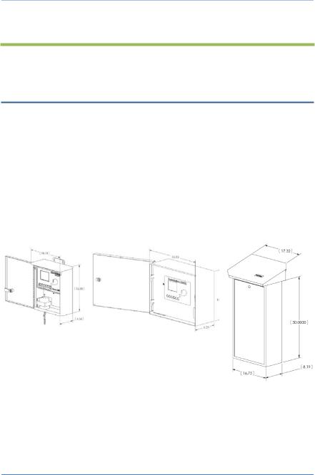
Cabinet Options
Your BaseStation 3200 will be installed in one of the following cabinets:
All cabinets are constructed from 16-gauge steel.
•C-series – Powder-coated indoor/outdoor wall mount cabinet
•X-series – Powder-coated (X) or stainless steel (XS) indoor/outdoor large wall mount cabinet
•P-series – Stainless steel pedestal cabinet
Note: All cabinet dimensions are in inches.
C-series |
X/XS-series |
P-series |
Follow the instructions in the installation guide that came with the enclosure.
Page 13

BaseStation 3200 Advanced Irrigation Controller Manual
Central Control and Remote Communication Options
The BaseStation 3200 is compatible with a number of remote communication options to enable connectivity to Baseline’s central control platforms including LiveView and BaseManager 2.0.
Remote Communication Options
The BaseStation 3200 controller is compatible with the following remote communication options:
•Cellular Modem
•Ethernet
•Wireless Ethernet (Wi-Fi)
•Ethernet Radio
•Long haul Ethernet
Note: To install the remote communication devices, refer to the instructions included with the device.
LiveView™
LiveView makes your controller accessible at anytime from anywhere, with any Internet-accessible device, just as if you were standing in front of it.
To take advantage of LiveView, the controller needs to be connected the Internet with one of the supported communication options. You access the LiveView interface through BaseManager 2.0.
Note: LiveView performance is limited with a cellular modem connection.
BaseManager™ 2.0
BaseManager is a powerful cloud-based central control and remote access platform that allows any BaseStation 3200™ controller to be managed remotely over the Internet. With BaseManager, you’ll be able to do everything you normally have to do at the controller, from the convenience of any Internet connected device.
In order for a BaseStation irrigation controller to connect to BaseManager, the controller must have access to the Internet. Every BaseStation 3200 controller has a built-in Ethernet port that is Internet ready. You can also connect the controller to the Internet through with one of the other supported communication options.
Note: Your organization can also run BaseManager on a self-hosted server.
For more information, refer to Connecting to BaseManager – Overview on page 87.
Page 14
BaseStation 3200 Advanced Irrigation Controller Manual
BL Commander
The BL-Commander is a handheld radio for activating valves while away from the BaseStation 3200 controller. The radio receiver is powered from the BL-3200X series controller and can be easily moved between controllers for field service and repair. More information is available on the Baseline web site (http://www.baselinesystems.com).
•BL Commander Handheld Remote Control
You can connect a BL Commander handheld remote control unit to the BaseStation 3200. The BL Commander unit is a special version of the popular TRC Commander remote control unit manufactured by Irrigation Remotes and is compatible with all TRC Commander accessories and antennas.
•BL Commander Permanent Mount Receiver Kits
A permanent receiver kit may be factory or field installed. It communicates digitally with the BaseStation 3200 unit via a special internal port in the controller. With this option, you can operate your controllers using a BL Commander handheld unit. The receiver kit has DIP switches to set group and unit security codes.
•BL Commander Mobile Receiver
A mobile receiver unit connects to any compatible 3200 controller through the remote control port on the front panel. The mobile receiver unit receives power from the controller.
•BL Commander Universal Receiver Adapter
You can use a Universal Receiver Adapter unit to operate older conventionally wired controllers with the BL Commander handheld remote control unit. You can operate up to 32 stations with the Universal Receiver Adapter. To turn zones on and off using the unit, you attach a special connection adapter to each valve wire, common, and to 24 VAC power.
Two-Wire Devices
The BaseStation 3200 can communicate with all of the following Baseline accessories:
•1, 2, and 4 valve biCoders
•12, 24, 36, and 48 zone 5200R series powered biCoders
•biSensor soil moisture sensors
•Flow sensor biCoders for connection to third-party flow sensors and master valves
•PFS series smart PVC flow sensors
•BHM series hydrometers – metal-body flow meter and master valve combination
•Pause biCoder – compatible with any standard normally closed pause device such as a rain switch or a wind switch
•Air temperature biCoder
•Pause button (also called a “coach’s button”)
Page 15

BaseStation 3200 Advanced Irrigation Controller Manual
•Pump relay biCoder
•Lightning arrestor/surge suppression devices
You can expand every BaseStation 3200 to support up to 200 zones using virtually any combination of two-wire and conventional wiring.
Total Supported Devices and Limits
The following table lists the total numbers of devices by type that can be connected to a BaseStation 3200. The BaseStation 3200 can communicate with a maximum of 110 devices (device loads) on the two-wire path within the layout and length limits outlined later in this section.
Two-Wire Device Type |
Total |
Device Loads |
|
|
|
Valve biCoders |
200 |
1 per biCoder |
5200R series biCoders |
20 |
2 per biCoder |
biSensors |
25 |
1 |
Master Valves/Pump Starts |
8 |
1 |
Flow Meters |
8 |
3 |
Event Devices |
8 |
1 |
Temperature Sensors |
8 |
1 |
The system supports up to 110 total device loads.
You can configure 200 zones in the 3200 or 3200R controller. Unused ports or serial numbers on biCoders do not occupy a zone address and do not count towards the 200 zone limit.
Page 16

BaseStation 3200 Advanced Irrigation Controller Manual
Maximum Concurrent Valves
The maximum number of concurrently operating valves is shown in the two tables below. The number of concurrent valves varies based on the total load count and wire length to the farthest device:
Maximum Wire Distances for 3200R and 5200R Series biCoders
Page 17

BaseStation 3200 Advanced Irrigation Controller Manual
3 – Wiring Guidelines
Review this section to find instructions for wiring your BaseStation 3200 irrigation controller and for connecting the standard and optional devices.
Conventional Irrigation Wiring Installation
BaseStation 3200R controllers and Baseline 5200R Series Powered biCoders connect directly to conventional 24 VAC irrigation wiring, with one wire for each valve plus a common wire. Additionally, these devices are capable of communicating to soil moisture sensors over specific terminals that are enabled to search for and communicate with Baseline biSensors.
Conventional Wiring Modules
You can equip each 3200R controller with 12, 24, 36, or 48 zones, depending on the cabinet.
One 12 or 24 zone connection module fits in a C-series cabinet. An X, XS, or P cabinet accommodates two 12 or 24 zone connection modules.
The terminal designations for each 12 or 24 zone connection module are shown in the diagram on the right, and include:
•Rain Sensor Port (Normally Closed)
Note: When you connect a rain click device directly to this port, the device will function globally without any programming. When the contacts on the device open, all watering will be set to Done and no watering will start until the next start time after the contacts have closed.
•Two-wire Port (Red and Black)
•Valve Common (x2)
•Master Valve/Pump Start terminals (2, designated VE1 and VE2) – you can re-address these terminals to control conventional zones if desired
•Sensor-over-valve-wire Ports (x2 for 12 zone, x4 for 24 zone) each with a status LED
•Standard valve wire ports (x10 for 12 zone, x20 for 24 zone)
Page 18

BaseStation 3200 Advanced Irrigation Controller Manual
Only two zones of any 12 zone block of terminals can be activated concurrently, plus VE1 and VE2, resulting in a total concurrency of 6 zones for a 24 zone unit.
You can connect Baseline biSensors directly to valve wires on the Sensor-over-valve-wire ports (A1, A2 and B1, B2).
BaseStation 3200R systems have built-in biCoders, and each screw terminal has a unique serial number. These serial numbers are listed on the wiring label that is included in the unit as shown in the illustration below.
Serial Numbers for zones 1-24 on a BL-5200 Series Powered biCoder™
Powered biCoders are preconfigured at the factory to assign zones 1 to 48 (depending on how many zones the unit is equipped with) to terminals 1 through 48. However, by using the specific serial number, you can reassign any terminal to any zone address. Refer to the topic on clearing a previous zone number assignment on page 31.
Connecting Valve Wires and Moisture Sensors over Valve Wires
You can connect Baseline biSensors directly to the valve wires on the Sensor-over-valve-wire Ports (A1, A2, B1, B2) on any 12 or 24 zone connection module.
BL-5200 Series Powered biCoder Wiring Example with One biSensor
1.Power off the two-wire when installing devices. Leave 24 to 36 inches of slack on the two-wire to allow for easy installation and maintenance.
2.Wire the sprinkler valves directly to the zone connectors and common connector.
3.Locate the biSensor near the closest valve location.
4.Connect the red wire from the biSensor to the power wire or pilot wire of the valve and black wire from the biSensor to the common wire of the solenoid using the provided 3M™ Direct Bury Splice Kit DBR/Y connector. It is critical that polarity be maintained.
Note: Use wire nuts to test communication, and then replace those wire nuts with 3M™ Direct Bury Splice Kit DBR/Y connectors before burying.
5.Follow the “Burying the biSensor” instructions, included with the biSensor.
6.Connect the pilot wire from the valve to the A1, A2, B1, or B2 terminals.
7.Press the biSensor update button and verify that the light above the terminal stays on.
8.Assign the biSensor and test its operation. Refer to Searching for and Assigning biSensors on page 36 and Testing a Specific Two-wire Device on page 99.
Page 19

BaseStation 3200 Advanced Irrigation Controller Manual
BL-5200 Series Powered biCoder Wiring Example with One biSensor
Expanding with Two-Wire
All BaseStation 3200 controllers are capable of communicating with Baseline biCoders and biSensors connected to a two-wire path. Any supported two-wire devices may be connected.
Two-Wire Expansion Example
Page 20

BaseStation 3200 Advanced Irrigation Controller Manual
Connecting to BL-5200R Series Wall Mount biCoders
Baseline 5200R Series Powered biCoders are specifically intended for retrofit applications and make combining several old controllers into a single BaseStation 3200 easy and affordable.
BL-5200X-R48 – 48 Zone Wall Mount biCoder in X-Series Cabinet
5200R Series Powered biCoders require 110 VAC power (240 VAC for –INT versions) and are available in C-series and X/XS-series wall mount cabinets, or P-series pedestals.
Example Wiring Diagram
BaseStation 3200R
BL-5200C-R24
Two-wire Path
biSensor |
Valve biCoders |
You can connect up to 20 5200R Series Powered biCoders to a single BaseStation 3200, which enables you to retrofit a large site with multiple controllers into a single BaseStation 3200 controller.
Page 21
BaseStation 3200 Advanced Irrigation Controller Manual
Two-Wire Installation
All BaseStation 3200 and 3200R controllers are equipped with a full-function two-wire port capable of connecting to valve biCoders, powered retrofit biCoders, biSensors, flow meters, and other devices. Because Baseline’s biLine protocol provides full bidirectional communications, you can connect all your irrigation accessories to the same two-wire path – saving time and money compared to conventional wiring.
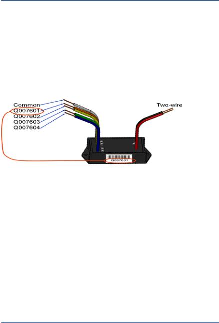
Two-Wire Serial Numbers
Each Baseline two-wire device has a unique serial number used to identify it. Serial numbers are labeled on all Baseline devices. For devices such as two or four zone biCoders, each output for the biCoder has a unique serial number, even if it only has one serial number listed on its label.
Serial Numbers for Four-zone biCoder
Two-Wire Connections and Layout
Baseline uses a proprietary digital protocol to communicate over two-wire. For the complete and up-to-date two-wire specification, please refer to the Resource Library on the Baseline web site.
Wire Connections
Install all wire connections in compliance with the connector manufacturer’s instructions, and make sure that the connections are fully waterproof.
Note: Use a 3M™ Direct Bury Splice Kit DBR/Y connector.
WARNING! Do not connect the two-wire and valve common terminals together because this will damage your BaseStation.
Baseline recommends that you allow 24 to 36 inches of strain relief at each wire connection to make valve box installation and troubleshooting easier and to prevent thermal expansion from pulling connections apart on long wire runs.
Page 22

BaseStation 3200 Advanced Irrigation Controller Manual
Wire Lengths
Total wire length supported depends on the gauge of the wire used.
Straight Run
Looped Run
Wire Layout
Straight line, star, looped, and combination configurations are supported.
The straight line and the star topology are the recommended layouts. To simplify the illustrations, only the last device is shown for most configurations. You can assume that other devices, both sensors and biCoders, are connected along the length of the two-wire path. On a star configuration, the topology has multiple last devices. Each device must separately meet the distance requirement.
While the loop topology might provide a more robust configuration, it is harder to trace the wiring errors that might occur. For this reason, Baseline recommends the other topologies over the loop.
Straight Line |
Looped |
Combination |
Star |
Page 23

BaseStation 3200 Advanced Irrigation Controller Manual
Wire Burial
Bury all wire at a depth appropriate to protect the wire from mechanical damage due to digging or aeration.
Baseline’s two-wire system operates under 30 VAC RMS, which is considered safe for shallow burial as outlined in the National Electric Code. All installations should comply with local electrical codes.
Removing a Two-Wire Device
If you want to remove a two-wire device, first you must physically disconnect it from the two-wire, and then you perform a Search operation from the device specific menu in the controller.
Example: If you need to remove a biSensor, physically disconnect the biSensor from the two-wire. Then go to the controller and turn the dial to Assign. Perform the steps to search for the biSensor (refer to Searching For and Assigning biSensors on page 36). When the controller detects that the biSensor is no longer connected, it will remove the device from the configuration.
Note: Refer to the Configuring Devices section on page 29 of this manual for the configuration procedures for the various two-wire devices.
Page 24
Loading...