

Page 1

BaseStation 3200
Advanced Irrigation Controller
User Manual
Firmware Version 12.9
July 11, 2013
Contents at a Glance
Section 1 Introduction
Section 2 System Components
Section 3 Wiring Guidelines
Section 4 BaseStation 3200 Interface
Section 5 Configuring Devices
Section 6 Initial Programming
Section 7 Flow Management & Monitoring
Section 8 Manual Operations
Section 9 System Management
Section 10 Reports, Messages, & Logs
Section 11 Troubleshooting
Section 12 Appendix
Customer Service 1-866-294-5847
Page 2

Baseline Inc.
www.baselinesystems.com
Phone 208-323-1634
FAX 208-323-1834
Toll Free 866-294-5847
©2013 Baseline Inc. All Rights Reserved.
Revision 2
Page 3

Table of Contents
1 – INTRODUCTION ................................................................................................................................. 1
How to Read this Manual .................................................................................................... 1
How to Irrigate Efficiently ................................................................................................... 1
Soil Moisture Content ......................................................................................................... 2
How to Use Soil Moisture Sensors Successfully ................................................................... 4
Choosing the Primary Zone for a Scheduling Group ............................................................ 5
Choosing the Sensor Location ............................................................................................. 5
Dealing with Slopes and Berms ...................................................................................... 5
Optimal biSensor Placement for Slopes and Berms ....................................................... 6
Burying the biSensor ........................................................................................................... 6
Turf Grass ...................................................................................................................... 6
Newly Seeded Turf Grass or New Sod ............................................................................ 6
Trees and Shrubs ........................................................................................................... 7
Installing biSensors with New Trees .............................................................................. 8
Shrubs and Other Ornamental Plants ............................................................................ 8
Gardens and Crop Plants ............................................................................................... 8
Watering Strategies ............................................................................................................ 8
Root Depth and Plant Water Efficiency ............................................................................... 9
Understanding Soak Cycling .............................................................................................. 10
Precipitation Rates vs. Infiltration Rates ........................................................................... 10
Precipitation Rates for Common Sprinkler Types ........................................................ 10
Estimated Infiltration Rates for Common Soil Types.................................................... 10
Using Soak Cycles with Soil Moisture Sensors ................................................................... 11
Distribution Uniformity..................................................................................................... 12
2 – SYSTEM COMPONENTS ................................................................................................................. 13
Cabinet Options ................................................................................................................ 13
Central Control and Remote Communication Options ....................................................... 14
Remote Communication Options ...................................................................................... 14
LiveView™ ......................................................................................................................... 14
BaseManager™ 2.0............................................................................................................ 14
BL Commander .................................................................................................................. 15
Two-Wire Devices ............................................................................................................. 15
Total Supported Devices and Limits .................................................................................. 16
Maximum Concurrent Valves....................................................................................... 17
Maximum Wire Distances for 3200R and 5200R Series biCoders ................................ 17
3 – WIRING GUIDELINES ..................................................................................................................... 18
Conventional Irrigation Wiring Installation ........................................................................ 18
Conventional Wiring Modules ........................................................................................... 18
Connecting Valve Wires and Moisture Sensors over Valve Wires ..................................... 19
BL-5200 Series Powered biCoder Wiring Example with One biSensor ......................... 19
Expanding with Two-Wire ................................................................................................. 20
Connecting to BL-5200R Series Wall Mount biCoders ....................................................... 21
Example Wiring Diagram ............................................................................................. 21
Two-Wire Installation ....................................................................................................... 22
Two-Wire Serial Numbers ................................................................................................. 22
Two-Wire Connections and Layout ................................................................................... 22
Wire Connections ........................................................................................................ 22
Wire Lengths ................................................................................................................ 23
Page i
Page 4

Wire Layout ................................................................................................................. 23
Wire Burial ................................................................................................................... 24
Removing a Two-Wire Device ........................................................................................... 24
4 – THE BASESTATION 3200 INTERFACE ...................................................................................... 25
Controller Front Panel Layout ........................................................................................... 25
Online Help ...................................................................................................................... 26
RUN Main Screen .............................................................................................................. 26
Status Colors .................................................................................................................... 27
On-Screen Reports ............................................................................................................ 27
Power Cycling or Restarting the Controller ........................................................................ 27
Setting the Controller Time and Date ................................................................................ 28
Checking the Firmware Version on Your Controller ........................................................... 28
5 – CONFIGURING DEVICES ................................................................................................................ 29
Searching For and Configuring Zone biCoders .................................................................... 29
Searching For biCoders (including Powered biCoders) ...................................................... 29
Assigning Valve biCoders to Zone Numbers ...................................................................... 30
Zone Numbers are Pre-Assigned in R-Series ................................................................ 30
To assign biCoders to zones ......................................................................................... 30
To clear a previous zone number assignment .............................................................. 31
Configuring Zone Settings ................................................................................................. 31
Adjusting the Valve Power Level for a biCoder ................................................................. 33
Searching For Start, Stop, & Pause Devices ........................................................................ 34
Searching For and Assigning Event biCoders ..................................................................... 34
Searching For and Assigning Soil Moisture Sensors (for Start, Stop, Pause Conditions) .... 35
Searching For and Assigning Air Temperature Sensors ..................................................... 35
Searching For and Assigning Other Devices ....................................................................... 36
Searching For and Assigning biSensors ............................................................................. 36
Searching For and Assigning Pump Start Devices and Master Valves................................ 37
Searching For and Assigning Flow Meters ......................................................................... 38
6 – INITIAL PROGRAMMING .............................................................................................................. 39
Setting Up Time-Based Watering ...................................................................................... 39
Setting Up a Timed Zone ................................................................................................... 39
To set up a timed zone................................................................................................. 39
Setting Up a Primary Zone ................................................................................................ 41
Prerequisites ................................................................................................................ 41
To assign a primary zone ............................................................................................. 41
Linking Zones (Creating a Scheduling Group) .................................................................... 42
Adjusting the Water Time Tracking Ratio of Linked Zones ................................................ 43
Using Soak Cycles ............................................................................................................. 44
To set up soak cycles for a zone ........................................................................................ 44
To disable soak cycles ....................................................................................................... 45
Setting Up Programs ......................................................................................................... 46
To set up the start times for a program ............................................................................ 46
To set up the start days for a program .............................................................................. 47
To set up program start days based on a historical calendar ............................................ 48
Prerequisites ................................................................................................................ 48
Instructions .................................................................................................................. 49
To set up the water windows for a program ..................................................................... 49
To set up concurrent zones for a program ........................................................................ 51
To set the priority for a program ....................................................................................... 52
To adjust programs for seasonal variations ...................................................................... 52
Page ii
Page 5

Associating Zones with a Program ..................................................................................... 53
Removing a Zone from a Program ..................................................................................... 54
Setting Up Soil Moisture Sensor Based Watering ............................................................... 54
Prerequisites for Watering with Soil Moisture Sensors ..................................................... 55
To configure your biSensors and set up watering strategies ............................................. 55
Understanding Lower & Upper Limit Watering Strategies .................................................. 56
Lower Limit ....................................................................................................................... 56
Upper Limit ....................................................................................................................... 57
Complying with Water Restrictions ................................................................................... 58
Setting Up Start, Stop, and Pause Conditions .................................................................... 59
To set up start, stop, pause conditions for event switches ............................................... 59
To set up start, stop, pause conditions for soil moisture sensors ..................................... 60
To set up start, stop, pause conditions for air temperature sensors ................................. 61
Setting Up Event Days ....................................................................................................... 62
7 – FLOW MANAGEMENT & MONITORING ..................................................................................... 63
Assigning Devices to Water Sources .................................................................................. 63
Setting Up a Water Source ................................................................................................ 64
To set up the water source ............................................................................................... 65
Setting Up Empty Conditions for a POC ............................................................................. 66
Setting Up a Booster Pump for a Program ......................................................................... 66
Assigning Water Sources to Mainlines ............................................................................... 67
Assigning Programs to Mainlines ...................................................................................... 68
Setting Up the Mainline Operating Limits .......................................................................... 68
To set up the mainline ...................................................................................................... 70
Learning Flow ................................................................................................................... 71
Learning the Flow by Zone ................................................................................................ 71
Learning the Flow by Program .......................................................................................... 72
Managing Multiple Flow Devices and Mainlines ................................................................ 72
8 – MANUAL OPERATIONS ................................................................................................................. 74
Forcing a Program to Start ................................................................................................ 74
Stopping an Active Program .............................................................................................. 75
Manually Starting/Stopping the Zones of a Program ......................................................... 75
Manually Running One or All Zones for a Fixed Time ......................................................... 76
Manually Running Zones for a Fixed Time ......................................................................... 77
Manually Running Programs for a Fixed Time .................................................................... 78
Manually Running a Pump or MV for a Fixed Time ............................................................ 78
Setting the System to OFF ................................................................................................. 79
9 – SYSTEM MANAGEMENT ................................................................................................................ 80
Selecting the Language for Online Help ............................................................................. 80
Setting Up Security for the Controller................................................................................ 80
Setting the Two-Wire to Always On .................................................................................. 81
Changing the Serial Number of Your Controller ................................................................. 81
Using the USB Data Functions ........................................................................................... 82
Backing Up Your System .................................................................................................... 82
Restoring Your System ...................................................................................................... 83
Exporting Log Files ............................................................................................................ 83
Erasing All Programming from the Controller .................................................................... 84
Erasing All Files from the Controller .................................................................................. 85
Updating the Controller Firmware .................................................................................... 85
To update the controller’s firmware from the Baseline web site with a USB drive ........... 86
Page iii
Page 6

To update the controller’s firmware from BaseManager .................................................. 87
Connecting to BaseManager – Overview ........................................................................... 87
Enabling the BaseManager Connection on the Controller ................................................ 88
Checking the Status of the BaseManager Connection ...................................................... 88
Activating Your BaseManager Account ............................................................................. 89
Getting More Information about BaseManager ................................................................ 89
Setting Up the Default Network Connection ...................................................................... 89
Setting Up a Static IP Address ........................................................................................... 90
Understanding the Ethernet Settings ................................................................................ 91
Enabling a Cell Modem Connection ................................................................................... 91
10 – REPORTS, MESSAGES, & LOGS .................................................................................................. 92
Zone Status ...................................................................................................................... 92
Status Colors .................................................................................................................... 93
Test All Report .................................................................................................................. 94
Moisture Sensor Data ....................................................................................................... 94
To display the Soil Moisture Sensor Data report ............................................................... 94
Program Run Time Report ................................................................................................. 95
To display the Program Run Time report .......................................................................... 95
Water Used ...................................................................................................................... 95
To display the Water Used report ..................................................................................... 95
Operator Messages ........................................................................................................... 96
To display the messages .................................................................................................... 96
Pause Messages ................................................................................................................ 96
11 – TROUBLESHOOTING ................................................................................................................... 99
Testing a Specific Two-wire Device .................................................................................... 99
Possible Statuses for Valve biCoders ................................................................................. 99
Possible Statuses for Soil Moisture Sensors (biSensors) ................................................. 100
Checking and Repairing Two-wire Device Assignments and Addresses .............................. 101
Testing All Devices ........................................................................................................... 102
Performing a Two-wire Blink Test .................................................................................... 102
Troubleshooting the Two-Wire: High Current or Shorted .................................................. 103
Diagnosing a Circuit Board Issue ..................................................................................... 104
Troubleshooting with a Milliamp Clamp Meter .............................................................. 104
Troubleshooting Manually .............................................................................................. 105
Troubleshooting: Lost Devices | No Response .................................................................. 105
12 – APPENDIX .................................................................................................................................... 106
Warranty ......................................................................................................................... 106
Tips for Setting Up Common Configurations ..................................................................... 107
Lower Threshold Moisture Sensor Based Watering ........................................................ 107
Upper Threshold Moisture Sensor Based Watering ........................................................ 107
BL-3200-R Hydrozone Worksheet ..................................................................................... 109
Existing Irrigation Controller Information ....................................................................... 109
Additional Information for Existing Programs ................................................................. 110
Programming Information for the BaseStation 3200 Controller ..................................... 110
Additional Information for New Programs ...................................................................... 112
Glossary of Terms ............................................................................................................ 113
Page iv
Page 7

BaseStation 3200 Advanced Irrigation Controller Manual
1 – Introduction
Congratulations on choosing the most capable commercial grade smart irrigation controller in the
world! You will find that the BaseStation 3200 is capable of dramatically reducing your water use
while improving the health and quality of your landscape. Fully central control compatible, the
BaseStation 3200 controller will typically pay for itself in one to two seasons based on water waste
reduction alone.
The BaseStation 3200 is specifically designed to help you irrigate more efficiently than any other
commercial irrigation controller. The 3200 supports multiple smart watering strategies, including
smart watering with soil moisture sensors and a historical ET calendar.
At Baseline, our mission is to forever change the way people water plants by providing the
smartest, easiest and most capable irrigation control products ever made. If you have feedback on
how we can make our products better, please do not hesitate to contact us.
IMPORTANT NOTE! Install all electrical components including the BaseStation controller in
compliance with local electrical and building codes.
How to Read this Manual
For first time users, sections 1 through 6 provide an overview of how to get your new BaseStation
3200 controller up and running quickly, while sections 7 through 12 provide information on
advanced functions and troubleshooting.
For additional information, you can also visit the Baseline web site at
http://www.baselinesystems.com
To get the most out of your BaseStation 3200, we recommend that you review the information in
this Introduction before you install and configure your system.
How to Irrigate Efficiently
This section covers some key concepts that are essential to better and more efficient irrigation.
When you irrigate properly, you will reduce or eliminate water waste and improve the health of
your plants.
All other considerations being equal, you will see better watering results with soil moisture sensors
than with any other currently available technology. When you set up your BaseStation 3200 to
water based on soil moisture sensor data, your system becomes a “closed loop” – in other words,
the soil moisture sensor directly measures the moisture in the root zone, and the controller adjusts
watering to maintain the desired moisture levels.
• Water deeply and infrequently. Studies show that watering deeply and infrequently
promotes deeper root growth and more drought tolerant plants.
Page 1
Page 8

BaseStation 3200 Advanced Irrigation Controller Manual
Watering deeply means that the soil should be wetted down to a depth of 6 inches or deeper
for grasses and 12 inches or deeper for trees and shrubs.
Watering infrequently means that the next irrigation event (or start time) should be delayed
as long as possible without stressing the plants.
• Deeper roots = more efficient plants. Plants with deeper roots are able to draw more
nutrients from a larger area of soil, making fertilizers and soil treatments more effective.
• Avoid runoff. Matching the application rate of irrigation to the infiltration rate of the soil is
critical to avoid runoff.
• Only apply the amount of water needed. Irrigation water is a supplement to natural rainfall –
you only need to apply the amount of water needed to return the soil to optimum moisture.
Irrigation water applied above the field capacity of the soil is wasted – water will
gravitationally sink through the soil below the root zone of the plants.
Unlike other irrigation controllers, the 3200 is specifically designed to make efficient irrigation easy.
Before you start setting up and programming your BaseStation 3200, it is helpful to understand the
following concepts:
• Soil Moisture Content
• How to Use Soil Moisture Sensors, including:
Hydrozones
Scheduling groups
Primary zones and linked zones
• Watering Strategies
• Root Depth and Plant Water Efficiency
• Soak Cycling
• Distribution Uniformity
The remainder of this section covers these key concepts in more detail.
Soil Moisture Content
Soil scientists and agronomists have been studying the plant-water-soil system for over 100 years.
Early work in irrigation efficiency focused on the estimation of soil moisture based on weather
information, plant water requirements, and soil information such as soil texture and slope. With
the availability of inexpensive and highly accurate soil moisture sensors, we are able to take soil
moisture based irrigation to a whole new level of efficiency and effectiveness.
With soil moisture sensors, your controller can operate like a thermostat for your landscape –
applying water when it is needed, and where it is needed.
Page 2
Page 9

BaseStation 3200 Advanced Irrigation Controller Manual
Drier
Saturation
The soil pores are filled with water and nearly all of the air in the
Field Capacity
The level of soil moisture left in the soil after drainage of the
Maximum
When the soil moisture content reaches this level, irrigation
Permanent
The minimal point of soil moisture where the plants wilt and
Oven Dry
When soil is dried in an oven, nearly all water is removed. This
To understand soil moisture based smart irrigation, you also need to understand the following
industry standard terms for soil moisture content.
soil has been displaced by water. Gravity exerts force on the
water contained in saturated soils, moving it deeper into the
ground (if possible). When this “gravitational water” moves
down through the soil, it becomes unavailable to plants.
gravitational water. If you irrigate to a level above field capacity,
it will result in runoff or drainage as gravitational water.
Allowed
Depletion
(MAD)
Wilt Point
Wetter
One key point is that water applied above field capacity is generally wasted – it gravitationally
moves down through the soil and becomes unavailable to plants. Excess water will also leech
nutrients from the soil into deeper soil layers, reducing the efficiency of fertilizers and soil
treatments.
To understand field capacity, it is often useful to think of a sponge. If you dunk a sponge in a bucket
of water and pull it out, water will gravimetrically drain from the sponge for a period of time. When
the dripping stops, the sponge will still be very wet. This moisture level is roughly equivalent to
field capacity in soils – water is no longer draining into lower soil layers and is held in the root zone
of the plants.
When your irrigation system maintains soil moisture content between field capacity and maximum
allowed depletion, you will find that your plants are healthier and your water use actually
decreases. Studies also show that appropriately varying the time between irrigation events in order
to allow the soil to dry to the chosen depletion point promotes deeper root growth and
subsequently more efficiency and drought tolerance from the plants.
needs to start. In most cases, the maximum allowed depletion
level is well before the plants begin to show visible signs of
stress. Irrigators typically start watering at or before MAD is
reached because they do not want their landscapes to show
signs of stress.
begin to die off.
moisture content is used to provide a reference for measuring
saturation, field capacity, and MAD.
Page 3
Page 10

BaseStation 3200 Advanced Irrigation Controller Manual
• Grass in full sun with rotors
• Grass in shade with rotors
How to Use Soil Moisture Sensors Successfully
The first key for success with soil moisture sensors is to consider the hydrozones that exist in your
landscaping. A hydrozone is a grouping of plants that have similar water usage and delivery
characteristics and can be watered the same. For example, each of the following landscaping areas
is a separate hydrozone:
• Grass in full sun with sprays
• Drip zones in full sun
After you have identified the hydrozones in your landscaping, determine which irrigation zones are
used to water those hydrozones, and then put the irrigation zones into scheduling groups based on
their common characteristics. Within the scheduling group, designate the zone where the sensor is
located to be the “primary” zone, and then you set up the watering strategy for the scheduling
group based on the readings from that sensor. You can link the other zones in the scheduling group
to the primary zone so they will be watered more or less relative to it. These zones are called
“linked” zones. For more information, refer to Linking Zones (Creating a Scheduling Group) on page
42.
A scheduling group can include any zones that:
• Require irrigation on the same frequency (for example, on the same days)
• Have similar plant types (such as turf, shrubs, or flowers)
• Do not have excessive differences in sun or wind exposure
• Are irrigated with similar water application technologies (assuming zones meet the criteria
above)
You can group spray, rotor, and multi-stream zones, as long as the difference in application rates is
less than 10x. You can also put drip zones into one group, and subsurface drip zones into another
group.
Consider the following example of a sports park that has four baseball fields and four soccer fields
in addition to some perimeter and parking lot shrub areas.
The irrigation manager for the park wants to water the infield areas of the baseball fields
differently from the outfields. The manager puts the zones that water the infields of all four
baseball diamonds into one scheduling group that is controlled by a single soil moisture sensor in
one of the infields.
• Grass in shade with sprays
• Drip zones in shade
Likewise, the manager puts all zones covering the outfields into a second scheduling group
controlled by a single moisture sensor in one of the outfields.
Because all the soccer fields have similar plant types and sun exposures, the irrigation manager can
group all zones for all the soccer fields together and control them with a single soil moisture sensor
located in one of the fields.
Page 4
Page 11

BaseStation 3200 Advanced Irrigation Controller Manual
Lastly, the irrigation manager breaks the parking lot and perimeter shrub beds into two scheduling
groups representing sunny and shady exposures.
In this way, the irrigation manager is able to configure 42 individual zones into 5 scheduling groups
that are controlled by 5 soil moisture sensors.
In the example above, the irrigation manager would configure the 5 scheduling groups for the
Upper Limit or Lower Limit watering strategy based on readings from the associated soil moisture
sensors. However, each scheduling group can be watered according to any watering strategy
appropriate for that section of the landscape.
Choosing the Primary Zone for a Scheduling Group
Because the zones in a scheduling group are naturally similar, any zone in a group can make a good
primary zone (the zone where the sensor is located). For large scheduling groups, or scheduling
groups with a higher level of variation in sun or wind exposure, choose a primary zone that:
• Requires irrigation the most frequently
• Has an average or greater sun and wind exposure for the scheduling group
IMPORTANT NOTE! The primary zone must be configured in the BaseStation 3200 system at an
address with a lower number than the other zones within the same scheduling group. For example,
if zones 1 – 50 are in one scheduling group, zone 1 would be the primary zone. For retrofits, you
may need to renumber your zones in order to meet this requirement.
Choosing the Sensor Location
You will achieve the best results by locating the biSensor in an area that is average for the zone and
ideally for the entire scheduling group. Avoid the following areas:
• Drainage areas where irrigation or rainwater pools or is channeled
• Areas immediately around hardscapes or that receive runoff water from hardscapes or
buildings
As long as the location of the sensor is average for the zone, you should achieve excellent water
efficiency.
Dealing with Slopes and Berms
Steep slopes and berms are possibly the most difficult landscape areas to irrigate efficiently. The
main issue is runoff, but often subsurface drainage issues result in low areas that get soaking wet
and high areas that are bone dry. When a berm is constructed, the central mass is typically
compacted, which can also cause water movement and drainage issues.
Soil moisture sensors are an excellent tool to optimize watering for slopes and berms because the
sensor can detect how much irrigation water is actually infiltrating the upper levels of the slope or
berm.
Page 5
Page 12
BaseStation 3200 Advanced Irrigation Controller Manual
Take care when you set the soak and cycle times for slopes and berms – for some slopes, you might
need to break the total run time into five or more cycles.
Optimal biSensor Placement for Slopes and Berms
If the slope or berm is irrigated as a part of a larger zone that is mostly level, Baseline recommends
that you place the sensor in the larger level area. However, for most efficient results, set up
separate zones to water the top, middle, and bottom of slopes and berms.
Burying the biSensor
Install the biSensor according to the installation instructions that are included with it. When
installing a biSensor in an established landscape, avoid disturbing the surrounding soil in order to
reduce the chance that adjustments will be needed later.
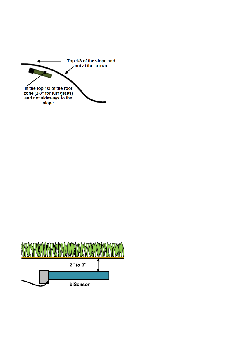
In general, you should install the biSensors in the top 1/3 of the root zone for the plant that is being
irrigated. In the case of turf grass, the top of the sensor blade should be 2 inches to 3 inches from
the bottom of the thatch layer.
Note: Burying the moisture sensor too deep can cause poor results. If the sensor is deeper than the
top 1/3 of the root zone, these roots can become too dry and the plants may become stressed.
Turf Grass
As previously stated, you should bury the sensor 2 inches to 3 inches below the thatch layer, or in
the top 1/3 of the root zone of the grass.
Newly Seeded Turf Grass or New Sod
The default watering strategies for the 3200 are intended to optimize water efficiency for
established plants and turf. This style of watering can result in poor performance for newly seeded
turf.
Page 6
Page 13

BaseStation 3200 Advanced Irrigation Controller Manual
If you want to install a sensor in newly seeded turf grass, follow the installation instructions and
bury the sensor at the proper depth. Baseline recommends that you water according to an
appropriate timed schedule until the grass has rooted sufficiently (typically 60 to 90 days) before
enabling a sensor based watering strategy. After the grass has rooted, you can convert the primary
zone to a sensor based watering strategy.
Likewise, newly installed sod has very shallow roots. Water the new sod on an appropriate time
schedule until it has rooted sufficiently to enable a sensor based watering strategy (typically 30 to
60 days).
Trees and Shrubs
If trees and shrubs are watered separately, a moisture sensor is an excellent tool to maintain their
health and beauty. Typically, multiple trees are watered by the same zone. If so, choose an average
tree, and install the biSensor in the top 1/3 of the root zone of the tree.
biSensor in the top 1/3 of the root zone of an established tree
Angling the sensor can monitor a deeper soil profile for trees that have deep root structures.
If the tree is watered with drip emitters or bubblers, install the sensor in a location that is not
directly under the emitter or bubbler to avoid partial watering of the whole root zone of the tree. If
multiple emitters are used for a single tree, a good rule of thumb is to install the sensor roughly
half way between two emitters and as much inside the root mass of the tree as possible without
damaging the roots.
Note: Root depth and water requirements for trees and shrubs vary much more greatly than for
turf. Consult an experienced Arborist or Master Gardener for specific guidelines for watering trees.
Most trees are watered along with turf in commercial landscapes. In this case, Baseline
recommends that you install biSensors in the turf areas and that you adjust the default run times of
zones with trees to ensure water application to 12 inches or whatever is required to optimize tree
health.
Page 7
Page 14

BaseStation 3200 Advanced Irrigation Controller Manual
Timed
Like all irrigation controllers, you can program the 3200 to run zones on specific
Historical
The BaseStation 3200 allows you to set the days between irrigation according to a
Installing biSensors with New Trees
In the case of new landscape with newly installed trees that are watered separately from turf
zones, it is important to make sure that the sensor is located as close to the root ball in the top 1/3
of the root ball as possible. Watering new trees with a sensor based watering strategy is a good
way to avoid inadvertently “drowning” new trees and shrubs due to overwatering.
Shrubs and Other Ornamental Plants
Many landscapes feature shrub zones that are separately watered from turf zones. Shrubs
generally have very different water needs from turf, so having separate zones is a good thing!
For shrub zones, choose a representative plant, and then install the in or close to the top 1/3 of the
root zone for the plant, without damaging the root structure of the plant.
If drip emitters or bubblers are used, install the sensor in a location that is not directly under the
emitter or bubbler to avoid partial watering of the whole root zone of the plant.
Gardens and Crop Plants
Sensors are excellent tools for maximizing crop results. They have been used for decades in
irrigated agriculture.
Garden and crop plant watering depends greatly on the type of plants being grown, and a
discussion of this topic is beyond the scope of this manual.
To plan a watering strategy for larger gardens or crops, Baseline recommends that you contact your
local Cooperative Extension Office. You can find a national register of the extension offices at:
http://www.csrees.usda.gov/Extension/
Watering Strategies
Each property is unique and has unique watering requirements. In order to support a broad range
of climate zones, plant types, landscape designs, and landscape usage requirements, the
BaseStation 3200 provides a variety of watering strategies.
The basic watering strategies supported by the 3200 are shown in the following table.
times and dates. Timed irrigation is the default setting for any zone that has not
been associated with a moisture sensor. Refer to Setting Up a Timed Zone on page
39.
Calendar
Page 8
Historical ET calendar. This watering strategy, unlike typical seasonal adjustments,
will promote deeper root growth and healthier plants throughout the season.
However, Historical ET based watering will not protect your landscape from
unusual weather patterns in any given season. Read the topic on setting up
program start days based on a historical calendar on page 48.
Page 15

BaseStation 3200 Advanced Irrigation Controller Manual
Lower
Also called Lower Threshold. In this soil moisture based, smart watering strategy,
Upper
Also called Upper Threshold. In this soil moisture based, smart watering strategy,
Limit
Limit
One important thing to remember about watering strategies – any one zone (or valve) can only be
watered according to one strategy. In other words, you cannot configure a zone to be watered
automatically using a soil moisture sensor and also be watered on a separate timed schedule.
Zones can be linked together and watered as a group, regardless of the watering strategy selected.
Refer to Linking Zones (Creating a Scheduling Group) on page 42for more information.
Also note that, even with soil moisture based watering strategies, it is important to program the
controller so it will put down as much water as required to maintain plant health during the heat of
the summer. The 3200 has built-in limits that control how much it is allowed to modify run times or
watering days before it assumes that there is an equipment malfunction of some kind.
irrigation is suspended or skipped until the soil dries to the lower limit, which may
be set manually, or set using the automatic calibration process. This watering
strategy naturally waters deeply and infrequently and promotes deeper root
growth in plants. The controller will water for a specified run time each time it is
allowed to water. When you are using this watering strategy, remember to ensure
that ½ inch or more of water is applied frequently enough to water sufficiently
during the hottest period of the season. Refer to Understanding Lower & Upper
Limit Watering Strategies on page 56.
irrigation events are scheduled for specific times and dates, but the total run time
is adjusted by the controller to bring soil moisture up and very slightly over field
capacity. This watering strategy is particularly useful for landscapes that need to
be at a desired moisture level on a regular schedule, such as sports fields or heavy
use parks. On these types of properties, damage to turf takes place when the soil
is either too wet or too dry. Refer to Understanding Lower & Upper Limit Watering
Strategies on page 56.
One of the most common irrigation programming mistakes is to apply too little water during the
hottest days of the season. Baseline recommends that, regardless of watering strategy, you
program each zone to water long enough to put down at least ½ inch of water each time the
controller is allowed to water.
For suggestions on programming your controller for these moisture sensor based watering
strategies, refer to Tips for Setting Up Common Configurations on page 107.
Root Depth and Plant Water Efficiency
Studies show that most plants, in particular standard turf grasses, do not grow deeper roots unless
prompted to do so. While some turf grass varietals rapidly grow deeper root structures when
properly watered, even Kentucky bluegrass will grow roots in excess of 12 inches in appropriate soil
textures when it is watered optimally.
Page 9
Page 16

BaseStation 3200 Advanced Irrigation Controller Manual
Watering deeply and infrequently on a consistent basis will promote healthier plants with deeper
root structures. As roots grow deeper, the plants are then able to access water in deeper and
typically wetter soil layers, making them even more water efficient. Plants with deeper roots are
also able to draw nutrients and fertilizers from deeper soil layers, making the plants more nutrition
efficient as well.
Understanding Soak Cycling
When you set up your irrigation programs, remember that the rate at which the irrigation
application devices apply water might be very different than the rate at which the soil in your
landscape can take up that water.
Soak cycling breaks the total run time into shorter water “cycles” with “soak” periods in between to
allow time for water to soak into the soil.
Precipitation Rates vs. Infiltration Rates
The precipitation rate, which is the rate at which sprinkler heads or drip emitters apply water to the
soil, is typically measured in inches, like rainfall.
Many soils only allow water infiltration at a rate of .25 inch per hour or less, whereas most head
types put down .50 inch per hour or more (much more in the case of some spray heads).
Also remember that head spacing and overlap directly influence the total precipitation rate for any
specific zone.
Precipitation Rates for Common Sprinkler Types
Spray Heads 1.00 inch to greater than 5.00 inches per hour
Gear Driven Rotors 0.25 inch to 0.65 inch per hour
Multi-stream Rotors 0.40 inch to 0.60 inch per hour
Drip Emitters Depends on area covered, rarely exceeds infiltration rate
Estimated Infiltration Rates for Common Soil Types
Course Sand 0.75 inch to 1.00 inch per hour
Fine Sand 0.50 inch to 0.75 inch per hour
Find Sandy Loam 0.35 inch to 0.50 inch per hour
Silt Loam 0.15 inch to 0.40 inch per hour
Clay Loam 0.10 inch to 0.20 inch per hour
As you can see from the tables above, most sprinkler heads have higher precipitation rates than the
infiltration rate of most soils.
Page 10
Page 17

BaseStation 3200 Advanced Irrigation Controller Manual
When the irrigation schedule puts down more water than the soil can take up, the excess water will
typically run off to the lowest point, leaving some areas of the landscape, or even the entire
irrigated landscape, under watered. Standing water also evaporates at a fairly high rate, especially
in the heat of the summer months, further reducing irrigation efficiency.
Even on a perfectly designed system, it is important to match the water application rate to the
infiltration rate of your soil. You can achieve this balance by breaking a total watering time for any
zone into multiple “cycles” (timed water applications) and “soaks” (timed wait periods, which will
allow the water applied in the last cycle to infiltrate into the soil before more water is applied).
The BaseStation 3200 has built-in support for soak cycling and has intelligent watering algorithms
that apply cycles in the optimal order to maximize water penetration and minimize evaporation
loss.
Note: Soak Cycling is required on all soil moisture based zones or scheduling groups in order to
ensure that the applied irrigation water is reaching the moisture sensor.
As a rule-of-thumb, Baseline recommends that you break the total water time for any zone into at
least 3 cycles, and configure the soak time between cycles to be at least twice the length of the
cycle time.
Note: One easy way to determine good cycle times is to turn a zone on and watch for first signs of
standing water or runoff. Set the cycle time to be no more than this amount of time.
Properly setting soak and cycle times will dramatically improve water penetration and watering
efficiency.
Using Soak Cycles with Soil Moisture Sensors
When you are using a soil moisture sensor based watering strategy or you are using a soil moisture
sensor to start or stop programs, you need to understand how the soak cycle settings will affect
your system.
• If you set a zone or program to start when the soil moisture sensor reading is less than the
limit, you should set up at least 3 soak cycles with a soak time that is at least twice as long as
the cycle time, and enable Intelligent Soak Cycles.
• If you set a zone or program to stop when the soil moisture sensor reading is greater than the
limit, you should set up at least 3 soak cycles, but DO NOT enable Intelligent Soak Cycles
because this setting could cause the program to stop before all zones have finished watering.
• If you want to maintain moisture within a narrow range, DO NOT use soak cycles.
• If you want to maintain moisture within a broader range, you should set up at least 3 soak
cycles, but DO NOT enable Intelligent Soak Cycles.
Page 11
Page 18

BaseStation 3200 Advanced Irrigation Controller Manual
Distribution Uniformity
Distribution uniformity (DU) refers to how evenly water is applied over the area in a particular zone
or landscape. This is generally driven by the choice of heads (spray, rotor, multi-stream, etc.) and
by the irrigation design.
In reality, it is very common that distribution uniformity is fairly low in irrigated landscapes. Poor
distribution uniformity is based on many factors beyond the scope of this manual, but it is
important to note that system problems such as uneven coverage will limit the effectiveness of
smart watering strategies.
Baseline’s experience is that high-uniformity systems can be built from nearly any head type, as
long as it is properly designed, installed and maintained.
IMPORTANT NOTE! The BaseStation 3200 controller can compensate for, but cannot solve,
distribution uniformity problems.
As you intelligently reduce water applied to any zone, you may notice stressed areas or brown
spots in your landscape. When this happens, you should first adjust your heads to make coverage
as even as possible. In extreme cases, you may find it advantageous to retrofit older heads with
new types of heads such as multi-stream rotors that apply water more evenly. Fixing distribution
uniformity issues has better long term results than increasing water times or moisture settings.
Every irrigation controller must be programmed to water to the “driest spot” in each zone. If the
difference between water applied at the driest spot is too great (especially if the wettest spot has
more than 3 times the water applied in the same period as to the dries spot) then you should take
steps to adjust your heads, their spacing, and their coverage to gain better uniformity.
You can quickly and easily measure the distribution uniformity of your landscape by placing catch
cups in any particular zone and then running that zone for a specific period of time. Auditing zones
in this manner will also give you precise information about how much water is applied per hour in
that zone, which makes it easy to set default water times. Baseline highly recommends that you
audit zones in order to determine uniformity and actual application rates.
Page 12
Page 19
BaseStation 3200 Advanced Irrigation Controller Manual
C-series
X/XS-series
P-series
2 – System Components
This section covers the components, devices, and communication options that are available for the
BaseStation 3200 irrigation controller. This section also gives the total supported devices and limits.
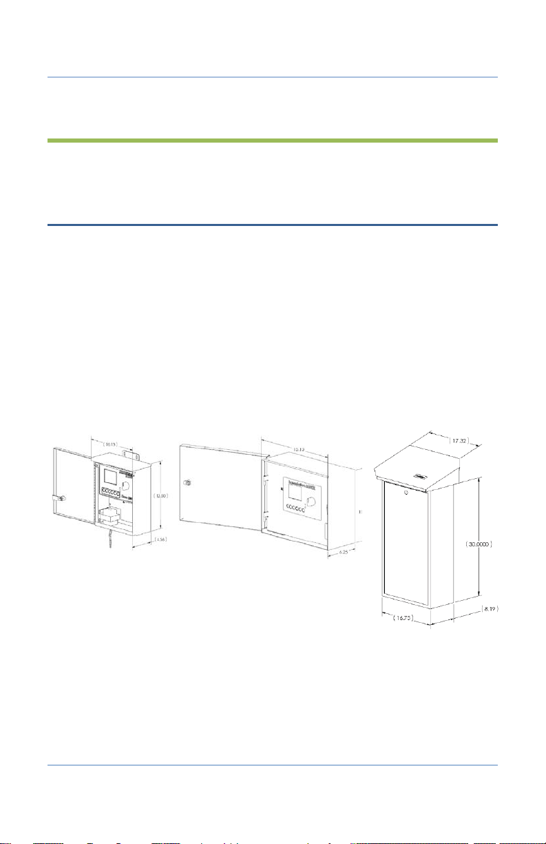
Cabinet Options
Your BaseStation 3200 will be installed in one of the following cabinets:
All cabinets are constructed from 16-gauge steel.
• C-series – Powder-coated indoor/outdoor wall mount cabinet
• X-series – Powder-coated (X) or stainless steel (XS) indoor/outdoor large wall mount cabinet
• P-series – Stainless steel pedestal cabinet
Note: All cabinet dimensions are in inches.
Follow the instructions in the installation guide that came with the enclosure.
Page 13
Page 20

BaseStation 3200 Advanced Irrigation Controller Manual
Central Control and Remote Communication Options
The BaseStation 3200 is compatible with a number of remote communication options to enable
connectivity to Baseline’s central control platforms including LiveView and BaseManager 2.0.
Remote Communication Options
The BaseStation 3200 controller is compatible with the following remote communication options:
• Cellular Modem
• Ethernet
• Wireless Ethernet (Wi-Fi)
• Ethernet Radio
• Long haul Ethernet
Note: To install the remote communication devices, refer to the instructions included with the
device.
LiveView™
LiveView makes your controller accessible at anytime from anywhere, with any Internet-accessible
device, just as if you were standing in front of it.
To take advantage of LiveView, the controller needs to be connected the Internet with one of the
supported communication options. You access the LiveView interface through BaseManager 2.0.
Note: LiveView performance is limited with a cellular modem connection.
BaseManager™ 2.0
BaseManager is a powerful cloud-based central control and remote access platform that allows any
BaseStation 3200™ controller to be managed remotely over the Internet. With BaseManager, you’ll
be able to do everything you normally have to do at the controller, from the convenience of any
Internet connected device.
In order for a BaseStation irrigation controller to connect to BaseManager, the controller must
have access to the Internet. Every BaseStation 3200 controller has a built-in Ethernet port that is
Internet ready. You can also connect the controller to the Internet through with one of the other
supported communication options.
Note: Your organization can also run BaseManager on a self-hosted server.
For more information, refer to Connecting to BaseManager – Overview on page 87.
Page 14
Page 21

BaseStation 3200 Advanced Irrigation Controller Manual
BL Commander
The BL-Commander is a handheld radio for activating valves while away from the BaseStation 3200
controller. The radio receiver is powered from the BL-3200X series controller and can be easily
moved between controllers for field service and repair. More information is available on the
Baseline web site (http://www.baselinesystems.com
• BL Commander Handheld Remote Control
You can connect a BL Commander handheld remote control unit to the BaseStation 3200. The
BL Commander unit is a special version of the popular TRC Commander remote control unit
manufactured by Irrigation Remotes and is compatible with all TRC Commander accessories
and antennas.
• BL Commander Permanent Mount Receiver Kits
A permanent receiver kit may be factory or field installed. It communicates digitally with the
BaseStation 3200 unit via a special internal port in the controller. With this option, you can
operate your controllers using a BL Commander handheld unit. The receiver kit has DIP
switches to set group and unit security codes.
• BL Commander Mobile Receiver
A mobile receiver unit connects to any compatible 3200 controller through the remote
control port on the front panel. The mobile receiver unit receives power from the controller.
• BL Commander Universal Receiver Adapter
You can use a Universal Receiver Adapter unit to operate older conventionally wired
controllers with the BL Commander handheld remote control unit. You can operate up to 32
stations with the Universal Receiver Adapter. To turn zones on and off using the unit, you
attach a special connection adapter to each valve wire, common, and to 24 VAC power.
).
Two-Wire Devices
The BaseStation 3200 can communicate with all of the following Baseline accessories:
• 1, 2, and 4 valve biCoders
• 12, 24, 36, and 48 zone 5200R series powered biCoders
• biSensor soil moisture sensors
• Flow sensor biCoders for connection to third-party flow sensors and master valves
• PFS series smart PVC flow sensors
• BHM series hydrometers – metal-body flow meter and master valve combination
• Pause biCoder – compatible with any standard normally closed pause device such as a rain
switch or a wind switch
• Air temperature biCoder
• Pause button (also called a “coach’s button”)
Page 15
Page 22

BaseStation 3200 Advanced Irrigation Controller Manual
Two-Wire Device Type
Total
Device Loads
Valve biCoders
200
1 per biCoder
5200R series biCoders
20
2 per biCoder
biSensors
25 1 Master Valves/Pump Starts
8 1 Flow Meters
8 3 Event Devices
8 1 Temperature Sensors
8
1
• Pump relay biCoder
• Lightning arrestor/surge suppression devices
You can expand every BaseStation 3200 to support up to 200 zones using virtually any combination
of two-wire and conventional wiring.
Total Supported Devices and Limits
The following table lists the total numbers of devices by type that can be connected to a
BaseStation 3200. The BaseStation 3200 can communicate with a maximum of 110 devices (device
loads) on the two-wire path within the layout and length limits outlined later in this section.
The system supports up to 110 total device loads.
You can configure 200 zones in the 3200 or 3200R controller. Unused ports or serial numbers on
biCoders do not occupy a zone address and do not count towards the 200 zone limit.
Page 16
Page 23
BaseStation 3200 Advanced Irrigation Controller Manual
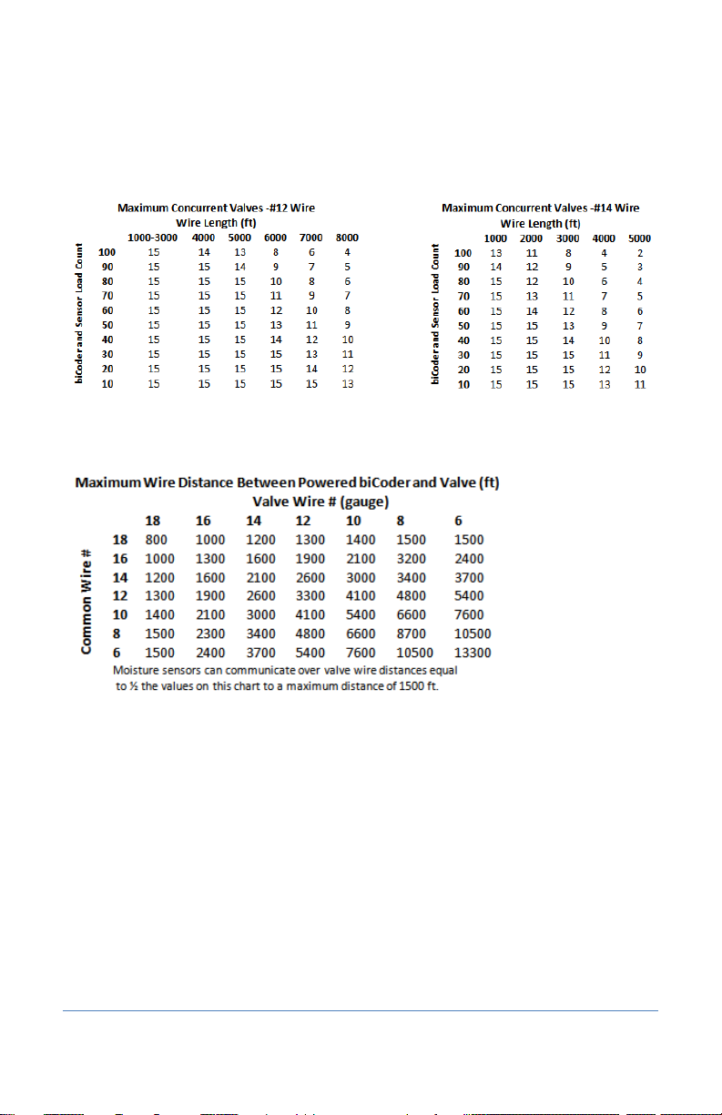
Maximum Concurrent Valves
The maximum number of concurrently operating valves is shown in the two tables below. The
number of concurrent valves varies based on the total load count and wire length to the farthest
device:
Maximum Wire Distances for 3200R and 5200R Series biCoders
Page 17
Page 24
BaseStation 3200 Advanced Irrigation Controller Manual
3 – Wiring Guidelines
Review this section to find instructions for wiring your BaseStation 3200 irrigation controller and
for connecting the standard and optional devices.
Conventional Irrigation Wiring Installation
BaseStation 3200R controllers and Baseline 5200R Series Powered biCoders connect directly to
conventional 24 VAC irrigation wiring, with one wire for each valve plus a common wire.
Additionally, these devices are capable of communicating to soil moisture sensors over specific
terminals that are enabled to search for and communicate with Baseline biSensors.
Conventional Wiring Modules
You can equip each 3200R controller with 12, 24, 36, or 48
zones, depending on the cabinet.
One 12 or 24 zone connection module fits in a C-series
cabinet. An X, XS, or P cabinet accommodates two 12 or 24
zone connection modules.
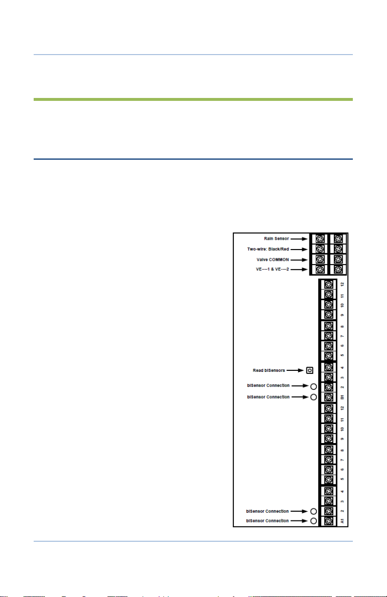
The terminal designations for each 12 or 24 zone
connection module are shown in the diagram on the right,
and include:
• Rain Sensor Port (Normally Closed)
Note: When you connect a rain click device directly
to this port, the device will function globally without
any programming. When the contacts on the device
open, all watering will be set to Done and no
watering will start until the next start time after the
contacts have closed.
• Two-wire Port (Red and Black)
• Valve Common (x2)
• Master Valve/Pump Start terminals (2, designated
VE1 and VE2) – you can re-address these terminals to
control conventional zones if desired
• Sensor-over-valve-wire Ports (x2 for 12 zone, x4 for
24 zone) each with a status LED
• Standard valve wire ports (x10 for 12 zone, x20 for 24
zone)
Page 18
Page 25
BaseStation 3200 Advanced Irrigation Controller Manual
Only two zones of any 12 zone block of terminals can be activated concurrently, plus VE1 and VE2,
resulting in a total concurrency of 6 zones for a 24 zone unit.
You can connect Baseline biSensors directly to valve wires on the Sensor-over-valve-wire ports (A1,
A2 and B1, B2).
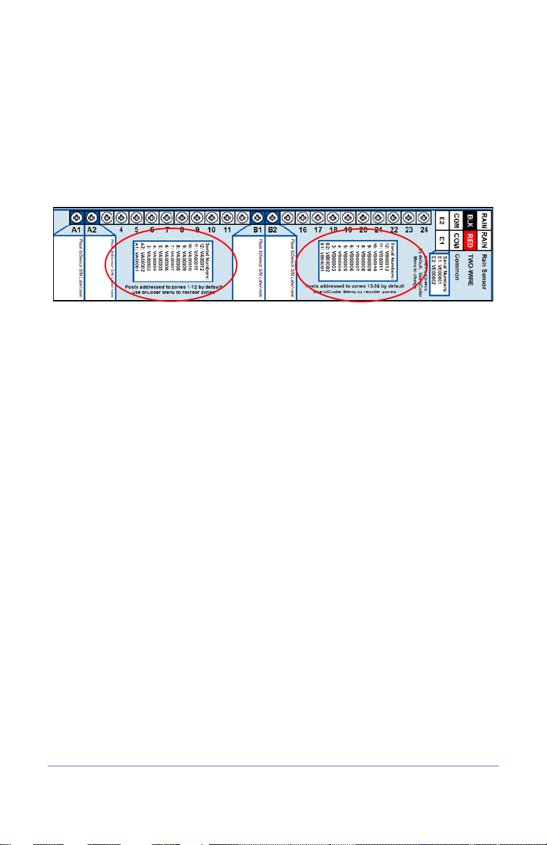
BaseStation 3200R systems have built-in biCoders, and each screw terminal has a unique serial
number. These serial numbers are listed on the wiring label that is included in the unit as shown in
the illustration below.
Serial Numbers for zones 1-24 on a BL-5200 Series Powered biCoder™
Powered biCoders are preconfigured at the factory to assign zones 1 to 48 (depending on how
many zones the unit is equipped with) to terminals 1 through 48. However, by using the specific
serial number, you can reassign any terminal to any zone address. Refer to the topic on clearing a
previous zone number assignment on page 31.
Connecting Valve Wires and Moisture Sensors over Valve Wires
You can connect Baseline biSensors directly to the valve wires on the Sensor-over-valve-wire Ports
(A1, A2, B1, B2) on any 12 or 24 zone connection module.
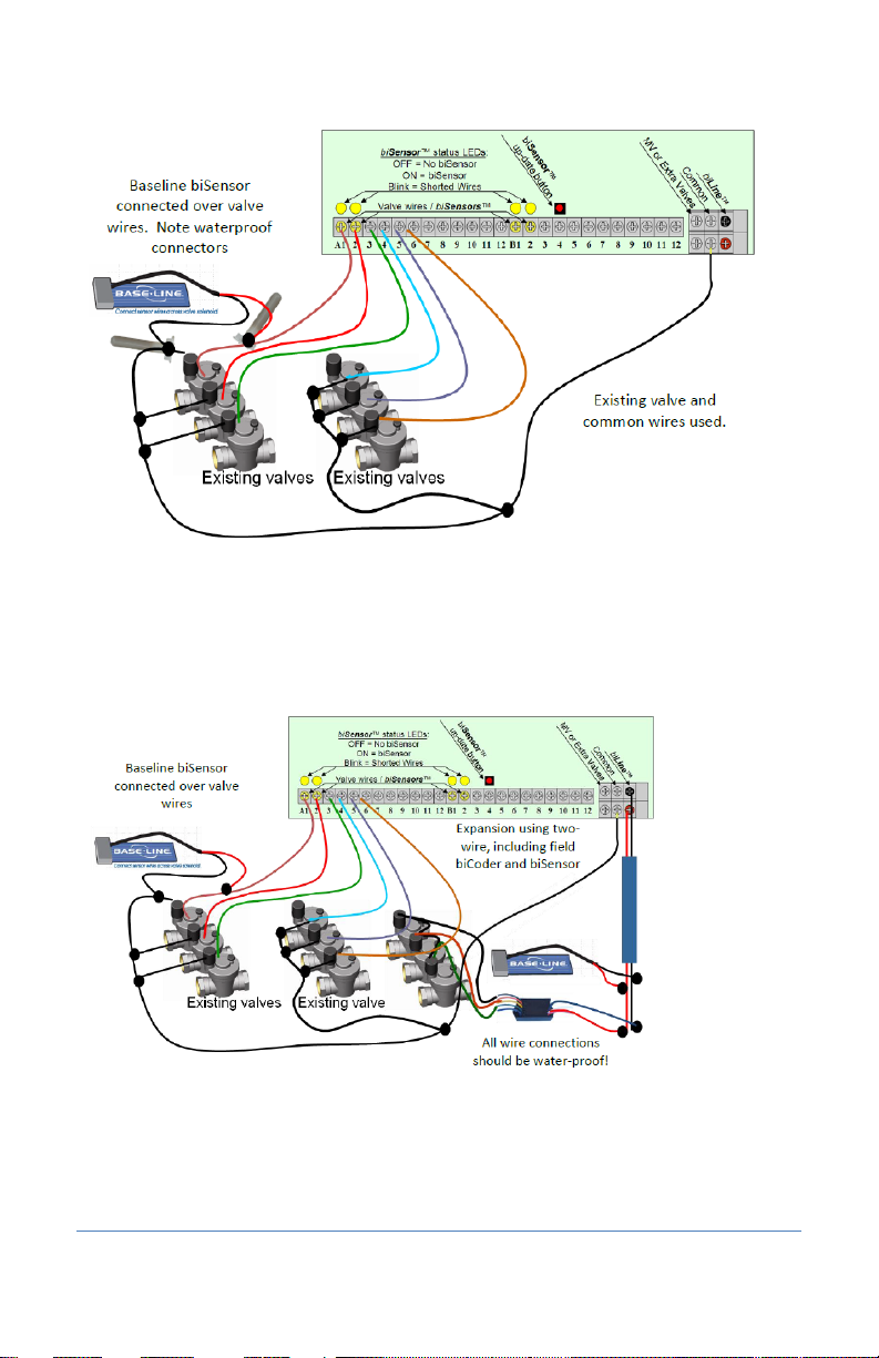
BL-5200 Series Powered biCoder Wiring Example with One biSensor
1. Power off the two-wire when installing devices. Leave 24 to 36 inches of slack on the
two-wire to allow for easy installation and maintenance.
2. Wire the sprinkler valves directly to the zone connectors and common connector.
3. Locate the biSensor near the closest valve location.
4. Connect the red wire from the biSensor to the power wire or pilot wire of the valve and black
wire from the biSensor to the common wire of the solenoid using the provided 3M™ Direct
Bury Splice Kit DBR/Y connector. It is critical that polarity be maintained.
Note: Use wire nuts to test communication, and then replace those wire nuts with 3M™
Direct Bury Splice Kit DBR/Y connectors before burying.
5. Follow the “Burying the biSensor” instructions, included with the biSensor.
6. Connect the pilot wire from the valve to the A1, A2, B1, or B2 terminals.
7. Press the biSensor update button and verify that the light above the terminal stays on.
8. Assign the biSensor and test its operation. Refer to Searching for and Assigning biSensors on
page 36 and Testing a Specific Two-wire Device on page 99.
Page 19
Page 26
BaseStation 3200 Advanced Irrigation Controller Manual
BL-5200 Series Powered biCoder Wiring Example with One biSensor
Expanding with Two-Wire
All BaseStation 3200 controllers are capable of communicating with Baseline biCoders and
biSensors connected to a two-wire path. Any supported two-wire devices may be connected.
Two-Wire Expansion Example
Page 20
Page 27
BaseStation 3200 Advanced Irrigation Controller Manual
BaseStation 3200R
BL-5200C-R24
Two-wire Path
biSensor
Valve biCoders
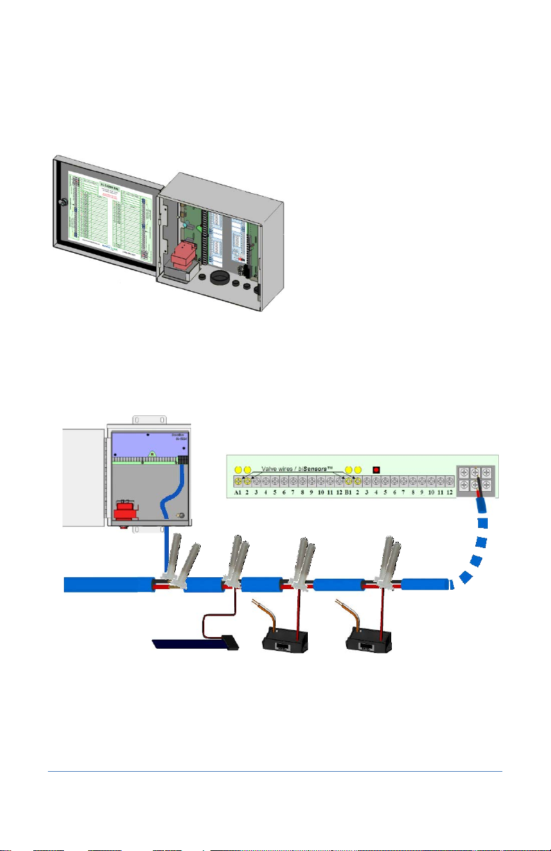
Connecting to BL-5200R Series Wall Mount biCoders
Baseline 5200R Series Powered biCoders are specifically intended for retrofit applications and make
combining several old controllers into a single BaseStation 3200 easy and affordable.
BL-5200X-R48 – 48 Zone Wall Mount biCoder in X-Series Cabinet
5200R Series Powered biCoders require 110 VAC power (240 VAC for –INT versions) and are
available in C-series and X/XS-series wall mount cabinets, or P-series pedestals.
Example Wiring Diagram
You can connect up to 20 5200R Series Powered biCoders to a single BaseStation 3200, which
enables you to retrofit a large site with multiple controllers into a single BaseStation 3200
controller.
Page 21
Page 28
BaseStation 3200 Advanced Irrigation Controller Manual
Two-Wire Installation
All BaseStation 3200 and 3200R controllers are equipped with a full-function two-wire port capable
of connecting to valve biCoders, powered retrofit biCoders, biSensors, flow meters, and other
devices. Because Baseline’s biLine protocol provides full bidirectional communications, you can
connect all your irrigation accessories to the same two-wire path – saving time and money
compared to conventional wiring.
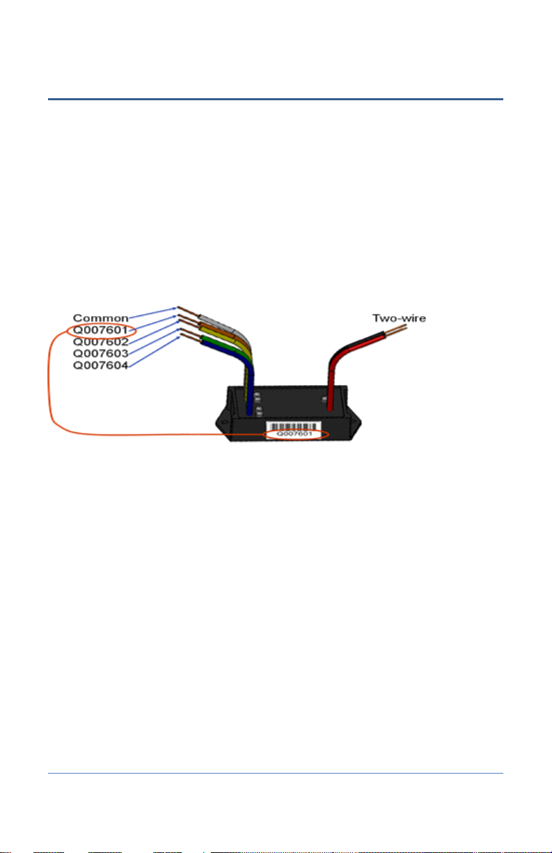
Two-Wire Serial Numbers
Each Baseline two-wire device has a unique serial number used to identify it. Serial numbers are
labeled on all Baseline devices. For devices such as two or four zone biCoders, each output for the
biCoder has a unique serial number, even if it only has one serial number listed on its label.
Serial Numbers for Four-zone biCoder
Two-Wire Connections and Layout
Baseline uses a proprietary digital protocol to communicate over two-wire. For the complete and
up-to-date two-wire specification, please refer to the Resource Library on the Baseline web site.
Wire Connections
Install all wire connections in compliance with the connector manufacturer’s instructions, and
make sure that the connections are fully waterproof.
Note: Use a 3M™ Direct Bury Splice Kit DBR/Y connector.
WARNING! Do not connect the two-wire and valve common terminals together because this will
damage your BaseStation.
Baseline recommends that you allow 24 to 36 inches of strain relief at each wire connection to
make valve box installation and troubleshooting easier and to prevent thermal expansion from
pulling connections apart on long wire runs.
Page 22
Page 29
BaseStation 3200 Advanced Irrigation Controller Manual
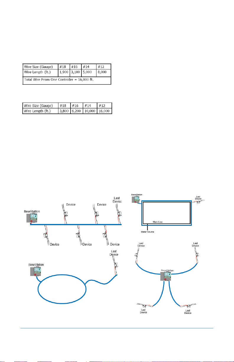
Straight Line
Looped
Combination
Star
Wire Lengths
Total wire length supported depends on the gauge of the wire used.
Straight Run
Looped Run
Wire Layout
Straight line, star, looped, and combination configurations are supported.
The straight line and the star topology are the recommended layouts. To simplify the illustrations,
only the last device is shown for most configurations. You can assume that other devices, both
sensors and biCoders, are connected along the length of the two-wire path. On a star
configuration, the topology has multiple last devices. Each device must separately meet the
distance requirement.
While the loop topology might provide a more robust configuration, it is harder to trace the wiring
errors that might occur. For this reason, Baseline recommends the other topologies over the loop.
Page 23
Page 30

BaseStation 3200 Advanced Irrigation Controller Manual
Wire Burial
Bury all wire at a depth appropriate to protect the wire from mechanical damage due to digging or
aeration.
Baseline’s two-wire system operates under 30 VAC RMS, which is considered safe for shallow burial
as outlined in the National Electric Code. All installations should comply with local electrical codes.
Removing a Two-Wire Device
If you want to remove a two-wire device, first you must physically disconnect it from the two-wire,
and then you perform a Search operation from the device specific menu in the controller.
Example: If you need to remove a biSensor, physically disconnect the biSensor from the two-wire.
Then go to the controller and turn the dial to Assign. Perform the steps to search for the biSensor
(refer to Searching For and Assigning biSensors on page 36). When the controller detects that the
biSensor is no longer connected, it will remove the device from the configuration.
Note: Refer to the Configuring Devices section on page 29 of this manual for the configuration
procedures for the various two-wire devices.
Page 24
Page 31

BaseStation 3200 Advanced Irrigation Controller Manual
+
Increases the value of the highlighted field or sequences through the available
options in the selected field
–
Decreases the value of the selected field, or sequences through the available
Next
Moves the highlighted selection to the next field on the display
Previous
Moves the highlighted selection to the previously selected field on the display
Back
Moves back to the previous menu and can sometimes be used to stop an
Enter
Applies the current selection and moves to the next item, or begins the operation
4 – The BaseStation 3200 Interface
Review this section to get familiar with the layout of the BaseStation 3200 interface. This
information covers the components of the front panel, the Online Help, the features of the main
screen, as well as the status colors and a brief overview of the on-screen reports.
Controller Front Panel Layout
(3) Dial – The dial is used to select the operation or programming mode of the controller.
(4) Buttons – The buttons are used to select programming elements, change their values, and
initiate operations like testing a zone.
options in the selected field
(1) USB Port – The USB port is
used for doing Backup and
Restore operations using a USB
drive (also known as a “thumb
drive” or a “flash drive”). The
USB port is also used for doing
firmware updates and
exporting operation log files.
(2) Display – The color display
indicates the current state of
the controller and is used to
display programming. This
display uses thin-film transistor
(TFT) technology to improve
image quality in outdoor
conditions including direct
sunlight and low light.
operation
Page 25
Page 32

BaseStation 3200 Advanced Irrigation Controller Manual
(5) Status LEDs – These two LEDs indicate the power status of the controller and the internal status
of the controller hardware. The upper light is normally ON, but it may blink when internal
diagnostics are run.
(6) Remote Control Port – This connector is used with the BL Commander hand-held radio remote
control to operate valves while away from the controller.
Online Help
At the bottom of every screen, there is a Help option
that displays the Online Help. The Online Help
describes how to use the buttons to change the
functions associated with that screen.
To display the help, press the Next or Previous
button to highlight the Help option at the bottom of
a screen, and then press the Enter button.
Press the Next button to move through the pages of
the Online Help.
Press the Previous button to back up.
Press the Back button to return to the controller screen.
The help can be displayed in Spanish. Refer to Selecting the Language for Online Help on page 80.
RUN Main Screen
When the controller dial is in the RUN position, the main screen displays the Zone Status report.
Page 26
Page 33

BaseStation 3200 Advanced Irrigation Controller Manual
Idle (watering done)
Active (watering)
Waiting to water
Soaking
Disabled
Paused
Off or Message (blinking)
Unused
Status Colors
The following colors display on the RUN screen to indicate the status of programs, master valves,
flow meters, and zones.
On-Screen Reports
The on-screen reports include the results of Test All, the soil moisture graph, the run time graph,
and the water used graph.
Note: Refer to Notes, Messages, and Logs on page 94 for the complete description of the on-screen
reports.
1. Turn the dial to the Reports position.
2. In the Select Report field, press the + or – button select the various reports.
Power Cycling or Restarting the Controller
If the controller goes into an abnormal state and does not respond, you might need to restart it.
1. Turn the dial to OFF.
2. Press and hold the – and + and Enter buttons for approximately 5 seconds.
3. After the screen goes blank, release the buttons.
4. Turn the dial to RUN. The controller restarts.
Page 27
Page 34

BaseStation 3200 Advanced Irrigation Controller Manual
Setting the Controller Time and Date
Set or change the controller date and time to match the current time and date. An inaccurate date
and time can cause watering events to be missed.
Note: When the controller is connected to BaseManager, the date and time are automatically set.
1. Turn the dial to the Time & Date position.
2. In the Time field, the hours place is
highlighted.
3. Press the + or – button to change the value.
4. Press the Next button to move to the minutes
place, and then press the + or – button to
change the value.
5. Press Next to continue moving through the
fields, and then press the + or – button to
change the value.
Note: If you made a change to the time or date and you want to revert to the previous
entries, press the Back button.
6. When you have finished making changes, turn the dial to the RUN position.
Checking the Firmware Version on Your Controller
Turn the dial to the Advanced position.
The version number of the firmware displays at the bottom of the screen.
Firmware updates are free for the life
of any Baseline controller as long as the
hardware is compatible. Baseline will
periodically release firmware updates
that enhance the usefulness of our
products or fix the occasional bug.
To determine whether the firmware
version on your controller is different
from the currently released version, go
to the Baseline web site
(www.baselinesystems.com
link in the menu on the left. Click the tab for your product. Review the information on that page, to
find out what the current firmware version is and then compare that with the version on your
controller.
If you find that an updated firmware version is available and you want to replace the firmware on
your controller with the new version, refer to Updating the Controller Firmware on page 85.
Page 28
). Click the Support tab and then click the Firmware Version Updates
Page 35

BaseStation 3200 Advanced Irrigation Controller Manual
5 – Configuring Devices
After you have finished connecting all your devices, you need to have the controller find those
devices so you can assign them.
The devices that you can attach to the BaseStation 3200 have serial numbers. The controller
identifies an attached device by its serial number. After you have searched for the attached
devices, you can assign each serial number to a specific purpose in the controller. For example, you
assign a valve biCoder’s serial number to the number or address of the zone that the valve waters.
The BaseStation 3200 controller accommodates up to 200 zones, and those zones are identified in
the controller with numbers 1 to 200. These numbers are also referred to as “addresses” because
they tell the controller where a specific device “lives.”
Searching For and Configuring Zone biCoders
Before you can configure any devices such as biCoders or biSensors in the controller, the controller
must find those devices and assign them. You can connect the following types of biCoders and
other two-wire devices directly to the two-wire path:
• Valve biCoders (decoders)
• biSensors (soil moisture sensors)
• Event biCoders and air temperature sensors
• Pump start devices and master valves
• Flow meters
Searching For biCoders (including Powered biCoders)
1. Turn the dial to the Assign position.
2. Press the + or – button to select Search in the Assign
screen.
3. Press the Enter button to search for biCoders. The search
may take several minutes to complete. You will see a
status screen like the one shown here while the search is
in progress.
The display shows the number of devices found and the
number of ports or addresses available.
Note: To cancel a search in progress, press the Back
button.
4. Continue to the procedure for assigning the biCoders to zones on page 30.
Page 29
Page 36

BaseStation 3200 Advanced Irrigation Controller Manual
Assigning Valve biCoders to Zone Numbers
You can assign any valve biCoder serial number to any zone number.
You may also wish to reassign and/or reorder certain zones in order to properly combine primary
and linked zones in a scheduling group.
The 3200 makes these assignments quick and easy to do, but be sure to document any changes
that you make. Failure to properly document assignments can cause confusion and frustration for
maintenance staff.
Zone Numbers are Pre-Assigned in R-Series
When you order a conventionally wired BaseStation 3200R controller, it is pre-programmed at the
factory so that that terminal 1 is assigned to zone 1, terminal 2 is assigned to zone 2, and so on. You
can change these zone numbers to organize scheduling groups, primary, and linked zones to
achieve optimal watering behavior.
Note: Baseline recommends that you use the Hydrozone Worksheet on page 109 to plan the
conversion from your existing irrigation controller to your new BaseStation 3200.
To change or re-order zone numbers in an R-series unit, perform the steps in the topic on clearing a
previous zone number assignment on page 31, and then assign each biCoder serial number to the
desired zone number. Refer to the topic on assigning biCoders to zones on page 30.
Note: The serial numbers for all terminals in 3200R controllers are shown on the label next to the
terminals. The serial numbers for terminals in 5200R biCoders are shown on the door label.
To assign biCoders to zones
1. If you have not searched for the biCoders, do that first. Refer to Searching For biCoders
(including Powered biCoders) on page 29.
2. With the dial in the Assign position and the
biCoders list displayed, press the + or – button
to select any unassigned decoder serial
number.
3. Press the Next or Previous button to move to
the Zone Assignments column and select an
available zone number.
4. Press the Enter button to assign the selected
biCoder to that zone number.
5. When you have finished making changes, turn
the dial to the RUN position.
Page 30
Page 37

BaseStation 3200 Advanced Irrigation Controller Manual
To clear a previous zone number assignment
You can reassign your biCoders to different zone numbers in order to accurately represent your
irrigation system and the primary zones and scheduling groups that you want to use.
1. If you have not searched for the biCoders, do that first. Refer to Searching For biCoders
(including Powered biCoders) on page 29.
2. With the dial in the Assign position and the
biCoder List displayed, press the + or – button
until Unassign is highlighted in the Decoders
list.
3. Press the Next button to move to the Zone
Assignments column.
4. Press the Next or Previous button to select
the zone that you want to clear.
5. Press the Enter button.
Note: If you cleared a zone number assignment so you can reassign certain zones in order to
properly combine primary and linked zones in a scheduling group, return to the topic on
assigning biCoders to zones (on page 30) to complete the assignments.
6. When you have finished making changes, turn the dial to the RUN position.
Configuring Zone Settings
After you have searched for your biCoders and assigned them to zones, you can configure the
various settings for each zone. The controller supports 200 standard zones.
1. Turn the dial to the Zones position. The Zones
screen displays for the first zone.
2. In the Zone field press the + or – button to
change the number to the zone that you want
to modify.
3. Press the Next button to move to the Zone
Mode field. Press the + or – button to change
the value in the field to one of the following
settings:
Note: If you change the mode of a zone to
Primary or from Primary to another mode,
you will potentially affect the programming of other zones. For example, a primary zone has
20 linked zones. If you change the mode of the primary zone to linked or timed, the links to
the 20 zones will be broken.
Primary – The zone within a scheduling group that all other zones are linked to.
Changing the programming on this zone will adjust the programming on all linked zones,
resulting in saved time and consistency. If you are using a biSensor, the primary zone is
the zone where the sensor is located.
Page 31
Page 38

BaseStation 3200 Advanced Irrigation Controller Manual
Linked – Within a zone group, there is one primary zone and all other zones are then
“linked” to the primary and will get their programming information from the primary
(water time, program, schedule, etc.)
Timed – Any zone programmed to water on a time/day schedule, rather than on a smart
irrigation schedule
4. Press the Next button to move to the Water Time field.
If you want to increase the value in the hours place, press the + button.
If you want to change the value in the minutes place, press the Next button, and then
press the + or – button.
Note: When you change the water time setting for a linked zone, notice that a
percentage displays to the left of the Water Time field. This percentage compares the
new value with the value in the Water Time field for the Primary zone and establishes a
tracking ratio. The ratio will be maintained when changes are made to the primary
zone’s water time.
Tip: Let the controller calculate the cycle time and soak time settings for you. Press the Next
button to move to the minutes placeholder in the Soak Time field, and then press the Back
button. The controller divides the time in the Water Time field by 3. This value is used for the
cycle time and the default soak time is 30 minutes.
5. Press the Next button to move to the Cycle Time field. If you are using soak cycles for this
zone, the cycle time defines the duration of each watering cycle interspersed with soak times.
Note: You cannot change the cycle time setting for a linked zone.
6. Press the Next button to move to the Soak Time field. If you are using soak cycles for this
zone, the soak time defines the duration of each soaking cycle interspersed with watering
times.
Note: You cannot change the soak time setting for a linked zone.
7. Press the Next button to move to the Flow field. If you know the gallons per minute flow for
this zone, you can press the + or – button to enter it in this field. You can also perform a Learn
Flow operation to update this field. Refer to Learning Flow by Zone on page 71.
8. Press the Next button to move to the Enabled field. Press the + or – button to toggle the
value in the field between YES and NO.
Note: If you want to prevent a zone from running, you can temporarily set the Enabled field
to NO. When you want the zone to run again, return to the Zones dial position and change
this setting to YES. This setting disables the zone in all programs.
9. The number in the Program field in the upper-left corner of the screen indicates what
program these zone settings are for. A zone can be removed from a program, assigned to a
different program, or assigned to more than one program. If you want to make a change to
how the zone is assigned to a program, perform one of the following actions; otherwise, skip
to step 10 of this procedure.
Note: To move to the Program field, press the Next or Previous button.
Page 32
Page 39

BaseStation 3200 Advanced Irrigation Controller Manual
To remove the zone from the current program, press the Previous button to return to
the Water Time field, and then press the – button to remove the watering time in the
field.
To assign the zone to a different program, perform the previous task to remove the
zone from the current program. Move to the Program field, and press the + or – button
to change the number to the new program that you want the zone to be assigned to.
To assign the zone to an additional program, move to the Program field, and press the +
or – button to change the number to the additional program that you want the zone to
be assigned to. Repeat steps 3 – 7 to configure the zone settings in the new program.
Note: The lower-left corner of the screen shows what programs the zone is assigned to.
10. After you have configured the settings for the current zone, perform one of the following
actions:
To configure another zone, press the Enter button until the number of the zone that you
want to configure displays in the Zone field at the top of the screen. Repeat steps 3 – 9.
When you have finished making changes, turn the dial to the RUN position.
Adjusting the Valve Power Level for a biCoder
If your irrigation system uses solenoids that have different power requirements, you can adjust the
valve power level of the biCoders that are attached to the zones associated with these solenoids.
Typically, you will perform this task under the guidance of Baseline Support.
Note: You only need to perform this procedure when the current read by the biCoder is less
than .110 Amps.
1. Turn the dial to the Advanced position.
2. Press the Next or Previous button to move to the Valve Power Setup option, and then press
the Enter button.
3. Press the + or – button to select the zone and biCoder that you want to adjust.
4. Press the Next button to move to the Valve Drive Power field, and then press the + or –
button to change the value.
You can adjust the valve power for any biCoder from a minimum of 1 to a maximum of 3. If a
biCoder does not support this feature, the word “Fixed” displays in the Valve Drive Power
field.
5. When you have finished making changes, turn the dial to the RUN position.
Page 33
Page 40

BaseStation 3200 Advanced Irrigation Controller Manual
Searching For Start, Stop, & Pause Devices
Programs can be started, stopped, or paused by the following conditions monitored by a dedicated
device:
• Whether the contacts on event biCoders are open or closed
• Whether moisture levels are above or below a specified percentage as monitored by a
biSensor
• Whether temperature values are above or below a specified level as monitored by either
moisture sensors or temperature sensors
Searching For and Assigning Event biCoders
The BaseStation 3200 supports 8 event biCoders.
1. Turn the dial to the Start, Stop, Pause position.
2. Press the Next or Previous button to highlight the Event Switches Setup option.
3. Press the Enter button. The Event Switches
screen displays.
4. All is highlighted in the Program column.
Perform one of the following:
To associate the event biCoder with the
full controller, continue to step 5.
To associate the event biCoder with a
specific program, press the + button to
move to that program number.
Continue to step 5.
5. Press the Next button to highlight Search.
6. Press the Enter button to search for event biCoders. The serial numbers of the biCoders are
shown in the Event Decoders column.
7. Press the + or – button to highlight the serial number of the event biCoder that you want to
assign.
8. Continue to the procedure for setting up the start, stop, and pause conditions for event
biCoders on page 59.
Page 34
Page 41

BaseStation 3200 Advanced Irrigation Controller Manual
Searching For and Assigning Soil Moisture Sensors (for Start, Stop, Pause Conditions)
The BaseStation 3200 supports 25 soil moisture sensors. Any soil moisture sensors used to monitor
start, stop, and pause conditions are included in the total count.
1. Turn the dial to the Start, Stop, Pause position.
2. Press the Next or Previous button to highlight the Moisture Control Setup option.
3. Press the Enter button. The Moisture Sensors
screen displays.
4. All is highlighted in the Program column.
Perform one of the following:
To associate the moisture sensor with
the full controller, continue to step 5.
To associate the moisture sensor with a
specific program, press the + button to
move to the program number. Continue
to step 5.
5. Press the Next button to highlight Search.
6. Press the Enter button to search for moisture sensors. The serial numbers of the sensors are
shown in the Moisture Sensors column.
7. Press the + or – button to highlight the serial number of the moisture sensor that you want to
assign.
8. Continue to the procedure for setting up the start, stop, and pause conditions for moisture
sensors on page 60.
Searching For and Assigning Air Temperature Sensors
The BaseStation 3200 supports 8 air temperature sensors.
1. Turn the dial to the Start, Stop, Pause
position.
2. Press the Next or Previous button to
highlight the Temperature Control Setup
option.
3. Press the Enter button. The Temperature
Sensors screen displays.
4. All is highlighted in the Program column.
Perform one of the following:
To associate the temperature sensor
with the full controller, continue to step
5.
To associate the temperature sensor with a specific program, press the + button to
move to the program number. Continue to step 5.
Page 35
Page 42

BaseStation 3200 Advanced Irrigation Controller Manual
5. Press the Next button to highlight Search.
6. Press the Enter button to search for temperature sensors. The serial numbers of the sensors
are shown in the Temperature Sensors column.
7. Press the + or – button to highlight the serial number of the temperature sensor that you
want to assign.
8. Continue to the procedure for setting up the start, stop, and pause conditions for air
temperature sensors on page 61.
Searching For and Assigning Other Devices
Searching For and Assigning biSensors
If you want to use soil moisture sensors (biSensors) to monitor your zones, you need to assign a
biSensor to a primary zone. If you have not configured any primary zones, you will not be able to
complete the following procedure. Refer to Setting Up a Primary Zone on page 41.
Note: The BaseStation 3200 supports 25 biSensors.
1. Turn the dial to the Smart Watering position.
2. The Moisture Sensor Assignments option should be highlighted. If it is not highlighted, press
the + or – button to highlight it.
3. Press the Enter button. The Assign Sensors
screen displays.
4. The Search option should be highlighted in
the column on the left. If it is not highlighted,
press the + or – button to highlight Search.
5. Press the Enter button. The system lists the
serial numbers of all biSensors that it finds.
Note: The BaseStation 3200 supports 25
biSensors.
6. Press the + or – button to highlight the serial number of the biSensor that you want to assign,
and then press the Enter button. The serial number moves from the list on the left to zone
address on the right.
7. When you have finished making changes, turn the dial to the RUN position.
Page 36
Page 43

BaseStation 3200 Advanced Irrigation Controller Manual
Searching For and Assigning Pump Start Devices and Master Valves
The BaseStation 3200 supports up to 8 normally open and/or normally closed master valves and/or
pump starts for the entire system. Valve decoders are assigned to Pump/MV numbers, and
flow+NOMV are assigned to MVs.
The following Pump/MV types are supported:
• Normally Closed – uses a traditional valve decoder and is assigned to a POC
• Normally Open – uses a traditional valve decoder, or is part of a Flow+NOMV decoder and is
assigned to a POC
• Main pump – uses a traditional valve decoder (or a pump relay decoder) and is assigned to a
POC
• Booster pump – uses a traditional valve decoder (or a pump relay decoder) and is assigned to
the list of programs
1. Turn the dial to the Water Sources position.
2. The Assign Decoders to Pumps/MVs option
should be highlighted in the box on the left. If
it is not highlighted, press the Next button to
highlight the option.
3. Press the Enter button. The Assign Pump/MV
screen displays.
4. The Search option should be highlighted in
the box on the left. If it is not highlighted,
press the + or – button to highlight Search.
5. Press the Enter button. The system lists the serial numbers of all pump/MV devices that it
finds.
6. Press the + or – button to highlight the serial number of the pump/MV device that you want
to assign, and then press the Enter button. The serial number moves from the list on the left
to an MV address row on the right.
7. When you have finished making changes, turn the dial to the RUN position.
Page 37
Page 44

BaseStation 3200 Advanced Irrigation Controller Manual
Searching For and Assigning Flow Meters
The BaseStation 3200 supports up to 8 flow sensors or meters, which manage and monitor flow
across a site as independent or connected hydraulic systems organized into mainline groupings.
In addition to finding flow biCoders, this search finds two-wire flow meters with integrated master
valves (both normally open and normally closed).
1. Turn the dial to the Water Sources position.
2. Press the Next or Previous button to select Flow Meters Setup, and then press the Enter
button.
3. Press the + or – button to select Search in the Flow Meters column.
4. Press the Enter button to search for flow meters. The system lists the serial numbers of all
flow meters that it finds.
5. Press the + or – button to select the flow
meter that you want to enable.
6. Press the Next button to move to the Enable
field. Press the + or – button to toggle the
value in the field between YES and NO.
7. Press the Next button to move to the K-Value
field.
Note: The K-Value is a calibration factor for a
flow device expressed in pulses per unit
volume. The K-Value is used to calibrate the
volumetric throughput of a flow device.
Manufacturers give the K-Value (or K-Factor) of their flow device in the device specification.
If the device is a Baseline flow biCoder, the correct K-Value automatically displays in the
field. Press the + or – button to change the K-Value if necessary.
If the device is not a Baseline flow biCoder, you need to enter the K-Value manually.
Find the K-Value for the device in the manufacturer’s documentation, and then press
the + or – button to enter the number in the K-Value field.
8. Press the Next button to move to the Offset field.
Note: The offset is a calibration factor for a flow device that compensates for limitations in
the device’s ability to measure small signals adequately. Manufacturers give the maximum
amount of offset associated with their flow device in the device specification.
If the device is a Baseline flow biCoder, the correct offset automatically displays in the
field. Press the + or – button to change the offset if necessary.
If the device is not a Baseline flow biCoder, you need to enter the offset manually. Find
the offset for the device in the manufacturer’s documentation, and then press the + or –
button to enter the number in the Offset field.
If the device does not have an offset value, you can enter the pulses per gallon in the
Pulses/GAL field to provide the same compensation factor as the offset.
9. When you have finished making changes, turn the dial to the RUN position.
Page 38
Page 45

BaseStation 3200 Advanced Irrigation Controller Manual
6 – Initial Programming
After you have assigned your devices as described in the previous section, you are ready to start
the initial programming on your BaseStation 3200 controller. Review the information in this section
to learn how to set up time-based watering for your zones, how to enable the soak cycles, and set
up your programs. If you are using a soil moisture sensor, be sure to read the information about
setting up soil moisture sensor based watering including the information about the watering
strategies.
Setting Up Time-Based Watering
The BaseStation 3200 provides the following methods for controlling the amount of water that is
applied to a zone:
• Watering based on time and schedule
• Watering based on soil moisture
• Watering based on a historical calendar
Even if you are planning to use soil moisture method or the historical calendar to control how much
water to apply, you still need to set up the time-based watering schedule for your zones.
Setting Up a Timed Zone
By default, all zones are set up as timed. If the mode of a zone was changed to linked or primary,
you can use this procedure to change the zone mode back to timed.
Implications for changing a zone within a scheduling group to timed:
• If you change a zone in the middle of your scheduling group from linked to timed, the linked
zones will continue to water as a group, but the zone that was changed to timed will now
water on a timed schedule.
• If you change a primary zone to timed, all zones that are linked to that primary zone will be
changed to timed.
To set up a timed zone
1. Turn the dial to the Zones position. The Zones
screen displays for the first zone.
2. In the Zone field, press the + or – button to
select the zone that you want to set up as
timed.
3. Press the Next button to move to the Zone
Mode field, and then press the + or – button
until Timed displays in the field.
Page 39
Page 46

BaseStation 3200 Advanced Irrigation Controller Manual
4. Press the Next button to move to the Water Time field.
To change the value in the hours place, press the + button.
To change the value in the minutes place, press the Next button, and then press the + or
– button.
Tip: Let the controller calculate the cycle time and soak time settings for you. Press the Next
button to move to the minutes placeholder in the Soak Time field, and then press the Back
button. The controller divides the time in the Water Time field by 3. This value is used for the
cycle time and the default soak time is 30 minutes.
5. Press the Next button to move to the Cycle Time field. If you are using soak cycles for this
zone, the cycle time defines the duration of each watering cycle interspersed with soak times.
6. Press the Next button to move to the Soak Time field. If you are using soak cycles for this
zone, the soak time defines the duration of each soaking cycle interspersed with watering
times.
7. Press the Next button to move to the Flow field. If you know the gallons per minute flow for
this zone, you can press the + or – button to enter it in this field. You can also perform a Learn
Flow operation to update this field. Refer to Learning Flow by Zone on page 71.
8. Verify that the number displayed in the Program field in the upper-left corner of the screen
matches the program in which you want to set up the timed zone.
If you want to set up the timed zone in a different program, press the Next button to
move to the Program field, and then press the + or – button to change the program
number.
If you want to remove a zone from one program and assign it to a different program,
refer to Configuring Zone Settings on page 31.
9. Press the Next button to move to the Enabled field, and then press the + or – button to toggle
between YES and NO. Set the value to YES.
10. After you have configured the settings for the current zone, perform one of the following
actions:
To configure another zone, press the Enter button until the number of the zone that you
want to configure displays in the Zone field at the top of the screen. Repeat steps 3 – 9.
When you have finished making changes, turn the dial to the RUN position.
Page 40
Page 47

BaseStation 3200 Advanced Irrigation Controller Manual
Setting Up a Primary Zone
A primary zone is the zone within a scheduling group that all other linked zones are linked to.
Changing the programming on this zone will adjust the programming on all linked zones, resulting
in saved time and consistency. If you are using a biSensor, the primary zone is the zone where the
sensor is located.
Note: The primary zones of a program always run first.
Prerequisites
• biCoders have been assigned to zones.
• If you are using soil moisture sensors, they have been installed and detected by the
controller.
• You know the number of the zone that waters the area where the sensor is installed.
To assign a primary zone
1. Turn the dial to the Zones position.
2. Verify that the number displayed in the Program field matches the program in which you
want to set up the primary zone. If the zone is enabled in multiple programs and you want to
set up the primary zone in a different program, press the + or – button to change the program
number.
Note: A zone can only be a primary zone in one program.
3. Press the Next button to move to the Zone field, and then press the + or – button to select
the zone that you want to assign as a primary zone.
4. Press the Next button to move to the Zone Mode field.
5. Press the + or – button until Primary displays in the Zone Mode field.
Note: If you change the mode of a zone to
Primary or from Primary to another mode,
you will potentially affect the programming of
other zones. For example, a primary zone has
20 linked zones. If you change the mode of
the primary zone to linked or timed, the links
to the 20 zones will be broken.
6. Repeat steps 2 – 5 for each primary zone with
a biSensor.
7. When you have finished making changes, turn
the dial to the RUN position.
Page 41
Page 48

BaseStation 3200 Advanced Irrigation Controller Manual
Linking Zones (Creating a Scheduling Group)
To make programming easier and more structured, the BaseStation 3200 provides a way to group
zones that have similar watering requirements. You create a scheduling group by designating a
zone within the group as the primary zone and then configuring the other zones in the group as
linked. These settings allow you to change the program for the primary zone and then
automatically apply those changes to the linked zones. For example, if your group has 10 zones,
you only need to make changes to the primary zone, and then all the changes will be automatically
applied to the other 9 zones.
1. Perform the procedure in Setting Up a Primary Zone (on page 41) first.
2. Turn the dial to the Zones position.
3. Verify that the number displayed in the Program field in the upper-left corner of the screen
matches the program in which you want to set up the scheduling group. If the zone is enabled
in multiple programs and you want to set up the scheduling group in a different program,
press the Next button to move to the Program field, and then press the + or – button to
change the program number.
Note: You can only link a zone to its primary zone within the same program. Linked zones
cannot cross programs.
4. In the Zone field, press the + or – button to select the zone that you want to link.
5. Press the Next button to move to the Zone Mode field.
6. Press the + button to change the entry in the field so it shows Linked-#.
7. To continue linking zones, press the Enter button until the number of the zone that you want
to link displays in the Zone field at the top of the screen.
8. Repeat steps 6 and 7 until you have linked all the zones in the group to the primary zone for
that group.
9. When you have finished making changes, turn the dial to the RUN position.
Page 42
Page 49

BaseStation 3200 Advanced Irrigation Controller Manual
Adjusting the Water Time Tracking Ratio of Linked Zones
You can change the water time tracking ratio of a linked zone in order to allow different water
times for zones within a group of linked zones. When the tracking ratio of a linked zone is set to
75% of the primary, the zone will run for that percentage of the water time of the primary zone (for
example, if the primary zone is set to water for 60 minutes and the linked zone tracking ratio is set
to 75%, the linked zone will water for 45 minutes because 75% of 60 is 45). If you change the water
time for the primary zone, each linked zone will be adjusted according to its tracking ratio value.
1. Turn the dial to the Zones position.
2. Verify that the number displayed in the
Program field matches the program in which
you want to adjust the tracking ratio. If the
zone is enabled in multiple programs and you
want to adjust the tracking ratio in a different
program, press the Next button to move to
the Program field, and then press the + or –
button to change the program number.
3. In the Zone field, press the + or – button to
select the zone that you want to adjust the
water time tracking ratio for.
4. Press the Next button to move to the Water Time field.
5. Press the + button to change the entry in the field.
Note: As you change the time in the field, the ratio percentage changes to indicate how the
time is related to the amount of time that the primary zone is scheduled to water. The
example in the illustration shows that 45 minutes is 100% of the watering time scheduled for
zone 2, so you know that zone 1 is also scheduled to water for 45 minutes. In this example, if
you were to increase the time in the Water Time field to 90 minutes, the ratio would change
to 200% to indicate that 90 minutes is double the amount of time that zone 1 is scheduled to
water.
6. To adjust the water time tracking ratio for other zones, press the Enter button until the
number of the zone that you want to adjust displays in the Zone field at the top of the screen.
7. Repeat steps 3 through 5 until you have adjusted the water time tracking ratio for all the
zones in the group.
8. When you have finished making changes, turn the dial to the RUN position.
Page 43
Page 50

BaseStation 3200 Advanced Irrigation Controller Manual
Using Soak Cycles
Because each type of soil has a different rate at which it can absorb water, you should set up the
cycle time and soak time (“soak cycles”) for your zones to ensure that water soaks into the soil
instead of being wasted. For example, if you are applying water at 0.4 inch per hour to an area of
clay soil that can only absorb water at 0.2 inch per hour, the water that does not soak into the soil
will either run off or evaporate.
It is especially important to use appropriate soak cycles when you are watering a slope.
To set up soak cycles for a zone
1. Turn the dial to the Zones position.
2. Verify that the number displayed in the Program field matches the program in which you
want to set up the soak cycles. If the zone is enabled in multiple programs and you want to
set up the soak cycles in a different program, press the + or – button to change the program
number.
3. Press the Next button to move to the Zone field, and then press the + or – button to select
the zone that you want to set up the soak cycles for.
Note: When you set the soak cycle times for a primary zone, the soak cycles will also be set
for all linked zones. The cycle time for linked zones is calculated based on the tracking ratio of
the primary zone cycle time. The soak times will be the same as that of the primary zone.
4. Press the Next button to move to the Water Time field.
To change the value in the hours place, press the + button.
To change the value in the minutes place, press the Next button, and then press the + or
– button.
Note: When you change the water time setting for a linked zone, notice that a
percentage displays to the left of the Water Time field. This percentage compares the
new value with the value in the Water Time field for the Primary zone and establishes a
tracking ratio. The ratio will be maintained when changes are made to the primary
zone’s water time.
Tip: Let the controller calculate the cycle time and soak time settings for you. Press the Next
button to move to the minutes placeholder in the Soak Time field, and then press the Back
button. The controller divides the time in the Water Time field by 3. This value is used for the
cycle time and the default soak time is 30 minutes.
5. Press the Next button to move to the Cycle Time field. If you are using soak cycles for this
zone, the cycle time defines the duration of each watering cycle interspersed with soak times.
To change the value in the hours place, press the + button.
To change the value in the minutes place, press the Next button, and then press the + or
– button.
Note: You cannot change the cycle time setting for a linked zone.
Page 44
Page 51

BaseStation 3200 Advanced Irrigation Controller Manual
6. Press the Next button to move to the Soak Time field. If you are using soak cycles for this
zone, the soak time defines the duration of each soaking cycle interspersed with watering
times.
To change the value in the hours place, press the + button.
To change the value in the minutes place, press the Next button, and then press the + or
– button.
Note: You cannot change the soak time setting for a linked zone.
7. When you have finished making changes, turn the dial to the RUN position.
In this example, the settings are shown for a
60-minute water time. Primary zone 1 waters for
20 minutes, and then allows that water to soak in
for 40 minutes. While zone 2 is soaking, other
zones can run. After the 40 minutes soak time, zone
2 will be allowed to run another 20 minutes after
any zone that is currently running finishes.
With these settings, zone 1 completes its 1 hour of
watering in three, 20-minute segments, with at
least a 40 minute soak time between them.
When there are many zones in a program, zones
will be cycled and soaked until all have been completed. Zones that have completed their soak
cycles are prioritized higher that zones that are still waiting to water so the first zones to start
watering will be the first to complete.
To disable soak cycles
1. Turn the dial to the Zones position.
2. Verify that the number displayed in the Program field matches the program in which you
want to disable the soak cycles. If the zone is enabled in multiple programs and you want to
disable the soak cycles in a different program, press the + or – button to change the program
number.
3. Press the Next button to move to the Zone field, and then press the + or – button to select
the zone that you want to disable the soak cycles for.
Note: When you disable the soak cycle for a primary zone, soak cycle is disabled for all linked
zones. The controller skips the linked zones when you press the + or – button to select a zone.
4. Press the Next button to move to the Cycle Time field, and then press the Back button to
change the value in the field to 0:00.
5. Press the Next button to move to the Soak Time field, and then press the Back button to
change the value in the field to 0:00.
6. When you have finished making changes, turn the dial to the RUN position.
Page 45
Page 52

BaseStation 3200 Advanced Irrigation Controller Manual
Setting Up Programs
The BaseStation 3200 supports 99 programs. The controller identifies each program with a number.
In many irrigation controllers, you set up the water times and the watering schedules in the
programs, but in the BaseStation 3200, water times are configured for the individual zones, and a
program provides the schedule for when the associated zones will water. The schedule has the
following components:
Start Times – Each program can have up to eight start times in a 24 hour period. Start times are set
in 5 minute increments from the top of the hour.
Start Days – If there are watering restrictions in your area, you might be able to use one of the
pre-configured day interval options in the controller to comply with the restrictions. Options are a
seven day schedule, even days of the month, odd days of the month, odd days of the month
excluding the 31
topic on setting up historical calendar watering for a program on page 48).
Water Windows – Water windows are used to select when watering will or will not be allowed. You
can configure water windows on a weekly basis (having the same water window settings for each
day of the week) or on a daily basis, where you can set each day of the week for a specific water
window schedule.
Concurrent Zones – Concurrent zones are the number of zones (valves) that can be operated at the
same time – typically limited by the amount of water available and the design flow of each of the
zones. You can set up the concurrent zones on a per program basis and have it automatically
managed using a flow device. You must also set the total number of concurrent zones for the
controller.
st
day of the month, fixed intervals, and historical ET calendar (explained in the
Advanced Setup – Each program has a watering priority (high, medium, low). When start events
are hit, the program with the highest priority gets first call on the water and time. A higher priority
program will pre-empt lower priority programs and will run to completion before the lower ones.
To set up the start times for a program
1. Turn the dial to the Programs position.
2. The Program Start Times Setup option
should be highlighted. If it is not highlighted,
press the Next button to highlight it.
3. Press the Enter button. The Start Times
screen displays.
4. Verify that the number displayed in the
Program field matches the program that you
want to set start times for. If you want to
select a different program, press the + or –
button to change the program number.
5. Press the Next button to move to the start
times grid.
6. Press the + or – button to set the time in the first cell.
Page 46
Page 53

BaseStation 3200 Advanced Irrigation Controller Manual
7. Press the Next button to move to the next cell in the start times grid, and then press the + or
– button to set additional start times as needed.
8. After you have configured the start times for the current program, perform one of the
following actions:
To configure start times for another program, press the Enter button until the number
of the program that you want to configure displays in the Program field at the top of the
screen. Repeat steps 5 – 7.
When you have finished making changes, turn the dial to the RUN position.
To set up the start days for a program
1. Turn the dial to the Programs position.
2. Press the Next button to highlight the Program Start Days Setup option, and then press the
Enter button. The Start Days screen displays.
3. Verify that the number displayed in the
Program field matches the program that you
want to set start days for. If you want to
select a different program, press the + or –
button to change the program number.
4. Press the Next button to move to the
Schedule Type field where you can select one
of the following intervals:
Days of the Week – After you select the
Days of the Week option, press the Next
button to set up the weekdays when
you want the program to start. By default, the boxes for the days of the week are
marked with a Y (Yes), which indicates that the program will start every day. If you want
to change a start day, press the Next button to select the day, and then press the + or –
button to change the setting.
Interval Days – This option enables you to set up a custom interval for the program start
days. Press the Next button to move to the Watering Interval Days field, and then press
the + or – button to change the setting. The next start date is calculated and entered in
the Next Start field. If you want to change the next start date, press the Previous button
to highlight the Next Start field, and then press the – button to change the date.
Note: You can decrease the start date, but you cannot increase it.
Even Days – Select Even to start the program only on the even numbered days of the
month.
Odd Days – Select Odd to start the program only on the odd numbered days of the
month.
Odd Skip 31 – Select Odd Skip 31 to start the program only on the odd numbered days
of the month, but skip the 31
st
day in order to maintain an every-two-day schedule
when crossing to a new month.
Page 47
Page 54

BaseStation 3200 Advanced Irrigation Controller Manual
Historical Calendar – Using the Historical Calendar watering schedule you can set up
custom start day intervals for the first half and second half of every month of the year.
This watering schedule works best in regions where landscapes are irrigated all year.
Refer to the topic for setting up program start days based on a historical calendar on
page 48.
5. After you have configured the start days for the current program, perform one of the
following actions:
To configure start days for another program, press the Enter button until the number of
the program that you want to configure displays in the Program field at the top of the
screen. Repeat step 4.
When you have finished making changes, turn the dial to the RUN position.
Note: A program that is started on one day will continue to run until it completes, even if it
needs to continue to the next day, which may or may not be a watering day. For example, if a
six-hour program starts at 10 PM on Monday, it will finish at 4 AM on Tuesday, even if
Tuesday is not a watering day.
To set up program start days based on a historical calendar
In the BaseStation 3200, one of the Start Day modes for a program is Historical Calendar. A
historical calendar uses ET (evapotranspiration) data to predict how frequently you will need to
irrigate over the course of an entire year. ET refers to the loss of moisture from the soil by
evaporation and by the transpiration of plants. Factors such as air temperature, humidity, solar
radiation, and wind speed affect the rate at which ET occurs. Scientists with the National Oceanic
and Atmospheric Administration (NOAA) continuously monitor climate data in all regions of the
United States. When this data is averaged over a 30 year period, historical ET values are generated
for each month of the year.
The Historical Calendar mode enables you to set up a watering schedule for the entire year that
compensates for seasonal changes without your having to adjust times and frequency multiple
times throughout the year.
If you set up a water time that applies ½ -¾ inch of water and then you change the frequency of
watering based on the historical ET needs for your area, the controller will water deeply and less
frequently and encourage the roots of your plants to grow deep.
Prerequisites
• Set zone water times that will apply ½ - ¾ inch of water during each watering cycle.
• Get the historical ET deficit data for your region. Consult with your local Agricultural
Cooperative Extension office – you can find a national register of the extension offices at:
http://www.csrees.usda.gov/Extension/
• Split each month of the year in half and determine how frequently you will need to water in
order to replace the amount of moisture used by your plant material since the last irrigation
event. Use the ET deficit data to determine the watering frequency.
Note: If you combine the Historical Calendar mode with the upper limit watering strategy
using biSensors, you will have a very effective watering schedule. The biSensor will monitor
the soil moisture in real-time and compensate for non-historical weather behavior by making
fine adjustments to the water time.
Page 48
Page 55

BaseStation 3200 Advanced Irrigation Controller Manual
Instructions
1. Turn the dial to the Programs position.
2. Press the Next button to highlight the Program Start Days Setup option, and then press the
Enter button. The Start Days screen displays.
3. Verify that the number displayed in the Program field matches the program that you want to
set the historical calendar watering schedule for. If you want to select a different program,
press the + or – button to change the program number.
4. Press the Next button to move to the Schedule Type field. Press the + button to move
through the options, and then stop when Historical Cal is displayed in the field.
5. Press the Next button to
move to the Next Start
field. The date is
calculated based on
today’s date and the
preconfigured interval.
6. Press the Next button to
move to the Day Interval
Calendar. The selected
day interval is indicated
by a colored box on a
number. The date field
displays the half month
that is represented by that number.
Note: The calendar displays 12 boxes that represent the months of the year. The numbers in
the boxes represent the day intervals for first half and second half of the month.
To increase or decrease the selected day interval, press the +/– buttons.
To turn watering off during the selected day interval, press the – button to set the
number to zero.
To move to and select a different day interval, press the Next button.
7. When you have finished configuring the Historical Calendar settings, turn the dial to the RUN
position.
Note: If you set up multiple programs to use the Historical Calendar settings, be sure to set
the program start dates so the interval is staggered. Refer to Setting Up the Start Days for a
Program on page 47.
To set up the water windows for a program
Water windows tell the controller when watering is allowed and not allowed. You can set water
windows for either Weekly (shown on illustration below) or daily – when moving from weekly to
daily, the weekly settings are copied to each day of the week.
Selecting daily water windows gives you hourly control of watering for each day of the week, and
for each program. A white square will pause watering for that hour, or keep a start time from
starting a program.
Page 49
Page 56

BaseStation 3200 Advanced Irrigation Controller Manual
1. Turn the dial to the Programs position.
2. Press the Next button to select the Program
Water Windows Setup option. The Water
Windows screen displays.
3. Press the + or – button to select the program
that you want to set up water windows for.
4. Press the Next button to move to the Water
Window Type field, and then press the + or –
button to select either Weekly or Daily.
Note: If you use “Weekly” to set up the water
windows and then you decide to convert to
“Daily,” the weekly settings are copied to each day of the week.
Selecting daily water windows gives you hourly control of watering for each day of the week
and for each program.
5. Press the Next button to move to the Day of the Week field. If you are using the “Weekly”
Water Window Type, you cannot change the setting in this field, but if you are using “Daily,”
press the + or – button to display the day of the week that you want to set up water windows
for.
6. Press the Next button to move to the ON/OFF field.
If the boxes in the grid are blue (allow watering), the field displays OFF. Press the Enter
button to turn all the water windows off.
If the boxes in the grid are white (do not allow watering), the field displays ON. Press the
Enter button to turn all the water windows on.
7. To make changes to the individual boxes in the grid, press the Next button. The color of the
number in the first box of the grid changes to red (indicating that you can change the setting
in that box).
To change the water setting for the time/day represented by that grid, press the +
button.
To move to next box in the grid, press the Next button.
Note: If you want to set up daily water windows, start by setting a basic profile in weekly
mode, and then change to daily mode to modify specific days (like a mow day). Pressing the
Enter button will maintain the current selected field and advance through the days of the
week.
8. When you have finished making changes, turn the dial to the RUN position.
Page 50
Page 57

BaseStation 3200 Advanced Irrigation Controller Manual
To set up concurrent zones for a program
Concurrent zones are the number of zones (valves) that can be operated at the same time –
typically limited by the amount of water available and the design flow of each of the zones. You can
set up the concurrent zones on a per program basis and have it automatically managed using a flow
device. You can also set the total number of concurrent zones for the controller.
In the BaseStation 3200, you manage the number of zones that can run concurrently at the
following levels:
• Mainline Flow Level – When you set up the design flow for the mainline and then set the
Concurrent Zones by Flow field to YES, the system uses the mainline design flow to determine
how many zones can run concurrently up to the program limits. Refer to Setting Up Mainline
Operating Limits on page 68.
• Program Level – If you want a program to water more than one zone at a time, you must
configure the Concurrent Zone settings at the program level.
Even if your system does not have a flow device, you can still use the Concurrent Zone
settings at the program level without having to input design flows for all zones and the
mainline.
When you have one or more flow devices, a good strategy is to set the program concurrency
limits to a reasonable maximum and then decrease specific programs that have some special
considerations (such as, the mainline branch is smaller, longer, or you want to slow the
completion time of a program, or if the two-wire length is very long and you want to control
the voltage drop by limiting the current to those valves).
1. Turn the dial to the Programs position.
2. Press the Next button to select the Concurrent Zones Setup option. The Concurrent Zones
screen displays.
3. In the Program column, press the + or – button to select the program that you want to set up
concurrent zones for.
4. Press the Next button to move to the
Concurrent Zones column, and then press the
+ or – button to change the value in the field.
Note: Consider electrical and water
constraints when you are setting up
concurrent zones.
5. Press the Next button to move to the Total
Allowed field, and then press the + or –
button to change the value in the field. This
field indicates the number of concurrent
zones for all programs added together.
6. When you have finished making changes, turn the dial to the RUN position.
Page 51
Page 58

BaseStation 3200 Advanced Irrigation Controller Manual
To set the priority for a program
When a start event is reached, the program with the highest priority gets first call on the water and
time.
A higher priority program “preempts” lower priority programs and runs to completion before the
lower ones.
1. Turn the dial to the Programs position.
2. Press the Next button to select the Advanced
Programs Setup option. The Advanced screen
displays.
3. In the Program field, press the + or – button to
select the program that you want to set the
priority for.
4. Press the Next button to move to the Water
Priority field, and then press the + button to
select one of the following priorities:
High – The program that you want to run
first
Medium – The program that you want to run after your high priority programs have
finished running
Low – The program that you want to run after all other programs have run
5. After you have configured the settings for the current program, perform one of the following
actions:
To configure another program, press the Enter button until the number of the program
that you want to configure displays in the Program field at the top of the screen. Repeat
step 4.
When you have finished making changes, turn the dial to the RUN position.
To adjust programs for seasonal variations
In order to provide a full range of functionality, the BaseStation 3200 controller firmware includes
an option to increase or decrease the amount of time all zones in a program will water. However,
we recommend that you use other methods for adjusting the amount of water that your irrigation
system is putting down. A healthier way to water turf is to always water deep (about the same
amount of time) and change the frequency of watering to maintain the correct moisture level. Use
the Day Intervals schedule for better results. Refer to Setting up the day intervals for a program on
page 47.
Page 52
Page 59

BaseStation 3200 Advanced Irrigation Controller Manual
1. Turn the dial to the Smart Watering position.
2. Press the Next or Previous button to select
Program Seasonal Adjust, and then press the
Enter button. The Season Adjust screen
displays and shows all programs set to 100%.
3. Press the + button to move to the program
where you want to adjust the percentage.
4. Press the Next button to move to the Budget
% column.
5. Press the + or – button to change the
percentage. You can set the percentage
between 10 and 500%.
6. After you have configured the settings for the current program, perform one of the following
actions:
To configure another program, press the Enter button until the number of the program
that you want to configure displays in the Program field at the top of the screen. Repeat
steps 4 and 5.
When you have finished making changes, turn the dial to the RUN position.
Associating Zones with a Program
In your landscape, you probably have zones that need to be watered every day (such as those that
water turf areas) and other zones that need to be watered less frequently (such as shrub borders).
In order to manage these different watering schedules, it is best to create separate programs for
the turf and the shrubs and then associate the zones that water the specific landscape area with
the appropriate program.
Prerequisites
• The zones have been correctly assigned in the controller.
• You know the numbers of the zones that water the specific landscape areas.
1. Turn the dial to the Zones position. The Zones
screen displays.
2. In the Zone field, press the + or – button to
select the number of the zone that you want
to associate with a program.
3. Press the Previous button to go to the
Program field.
4. Press the + or – button to select the program
that you want the zone to be associated with.
Page 53
Page 60

BaseStation 3200 Advanced Irrigation Controller Manual
5. Complete the other zone fields according to the instructions in Configuring Zone Settings on
page 31.
Note: Zones can be associated with multiple programs. Whenever a zone has a water time set
in a program, the zone is associated with the program. The programs that the zone is
associated with are shown in the lower-left corner of the screen.
6. Repeat steps 2 – 5 to associate all zones with a specific program.
7. When you have finished making changes, turn the dial to the RUN position.
Removing a Zone from a Program
Zones can be associated with multiple programs. Whenever a zone has a water time set in a
program, the zone is associated with the program. The programs that the zone is associated with
are shown in the lower-left corner of the screen.
1. Turn the dial to the Zones position. The Zones screen displays.
2. In the Zone field, press the + or – button to select the number of the zone that you want to
remove from a program.
3. Press the Previous button to go to the
Program field.
4. Press the + or – button to select the program
that you want the zone to be removed from.
5. Press the Next button to move to the Water
Time field.
6. When the hours placeholder is highlighted,
press the – button to remove the time from
the Water Time field.
7. When you have finished making changes, turn the dial to the RUN position.
Setting Up Soil Moisture Sensor Based Watering
You can take the guesswork out of your watering decisions by setting up soil moisture sensor based
watering. The biSensor measures soil moisture where the plants need it – at the root level.
When you have a biSensor installed, the BaseStation 3200 enables you to set up one of the
following water strategies:
• Timed – Waters without biSensor control, but provides a log of daily moisture levels.
Note: Be sure to use the Timed water strategy with new grass. After the root zone is
established, you can change to one of the other strategies.
• Lower Limit – Prevents watering until the moisture level drops below the limit, and then a full
water cycle will run. The user sets and manages the limit and the water time.
Page 54
Page 61

BaseStation 3200 Advanced Irrigation Controller Manual
• Upper Limit – Allows watering at each start time, but the water time is adjusted to replenish
the moisture to field capacity. The user sets and manages the limit and the base water time.
Ensure that ½ inch or more of water is applied frequently enough to water sufficiently during
the hottest period of the season.
Make sure that you have soak cycles properly set up for the zones that will be using soil
moisture based watering. In addition to allowing the applied water to soak into the soil,
soak cycles allow time for the water to reach the biSensor depth so the soil moisture
readings are accurate. Refer to Using Soak Cycles on page 44.
Prerequisites for Watering with Soil Moisture Sensors
• Your biSensors are installed and assigned in the BaseStation 3200. Make sure to assign the
correct biSensor to its primary zone. Making an incorrect assignment here will result in
unexpected and confusing water behavior. Refer to Searching For and Assigning biSensors on
page 36.
• You have created scheduling groups (a primary zone with linked zones) that combine areas
with similar watering needs (hydrozones). For example, the zones that water the softball field
would be in one scheduling group and the zones that water the north lawn between the
sidewalk and the building would be in another scheduling group. Refer to Linking Zones
(Creating a Scheduling Group) on page 42.
To configure your biSensors and set up watering strategies
1. Turn the dial to the Smart Watering position.
2. Press the Next button to select Moisture
Sensor Setup, and then press the Enter
button. The Sensor Setup screen displays.
3. If you have more than one biSensor installed
and assigned to a primary zone, verify that the
correct primary zone displays in the Sensor
Primary Zone field (the serial number of the
assigned biSensor displays in the lower-left
corner of the screen). If the biSensor that you
want to configure is not displayed in the field,
press the + or – button to select the correct one.
4. Press the Next button to move to the Water Strategy field, and then press the + or – button
to select the water strategy that you want to use.
IMPORTANT NOTE! If you select the Upper or Lower Limit strategies, be sure to read the
information below for a complete explanation of these strategies.
5. Press the Next button to move to the Upper/Lower Limit field (the field that displays
depends on the water strategy that you selected). Press the + or – button to change the
number in the field.
6. Press the Next button to move to the Limit Adjustment field.
Note: This field is typically used to offset the limit set by a calibration cycle. If you think that
you might need to use this field, contact Baseline Support for help.
Page 55
Page 62

BaseStation 3200 Advanced Irrigation Controller Manual
7. Press the Next button to move to the Calibration Cycle field.
Never – No calibration cycle will be performed
One Time – A single calibration cycle will be performed at the next start time
Monthly – A calibration cycle will be performed each month at the first start time
Note: Calibration cycles require that soak cycles be enabled. When you set these watering
strategies, soak cycles will be automatically enabled. You may change the settings to meet
your specific needs, but if you disable the soak cycles, the calibration cycle will fail.
8. When you have finished making changes, turn the dial to the RUN position.
Note: If for any reason the biSensor becomes damaged or fails (12 hours of failed data or
communication) the corresponding primary zone and linked zones will water based on a
timed operating mode which is based on set water times and program schedule.
Understanding Lower & Upper Limit Watering Strategies
Lower Limit
This water strategy provides an excellent way to achieve healthy, deep-rooted grass. You can either
set the lower limit manually or you can have the controller perform a calibration cycle in order to
calculate the limit. Set the lower limit at the maximum allowable depletion moisture level, just
before the lawn begins to stress or wilt.
When you choose the Lower water strategy, you must set and then manage the lower watering
limit. This water strategy works well when you are not constrained by specific water days. Schedule
the program to water every day, and then let the biSensor determine which days to skip by
monitoring the moisture level. The controller only waters when the moisture level has dropped
below the lower limit, and then a full water cycle runs.
The best way to set the lower limit is to have the controller do an initial calibration cycle. Set the
Calibrate field to One Time. The calibration cycle will run during the first normally scheduled water
time that is at least two days after the biSensor installation. The system sets an initial lower limit
based on the calibration.
You have the option to adjust the auto limit by entering a value in the Limit Adjustment field. This
adjustment is added to the limit to make the soil a little wetter or a little drier than the controller
set limit.
Lower Limit Programming Requirements
• Set zone water times to apply ½ - ¾ inch of water
• Set program to start every day of the week as allowed by local watering restrictions (the
biSensor will block watering until it is needed)
• Enable soak-cycles
• Use the default lower limit water strategy to begin with
Page 56
Page 63

BaseStation 3200 Advanced Irrigation Controller Manual
The first calibration cycle occurs on the first start time after a biSensor has been
installed for at least 48 hours.
A calibration cycle will calculate limits 12 to 15 hours after watering is complete on the
primary zone.
A calibration cycle will extend the programmed zone water time if needed to determine
the soil saturation point - if the ground is very dry (or if the water time is too short), the
water time could extend to twice the programmed time.
If a calibration cycle cannot determine the soil saturation point, the calibration cycle will
fail – posting an alert and setting a default limit.
Lower Limit Watering Behaviors
• It is uncertain which days of the week when watering will occur – use water windows or block
a day to specify a mow day.
• The water time for a program is fixed, so the end time is predictable to the extent that
multiple programs may all be trying to water on the same day.
Upper Limit
This water strategy varies the zone water time each time the program runs in order to apply
enough water to raise the moisture level to field capacity. Soak cycles are critical for this mode
because the controller monitors the moisture level as water is applied. At the end of each soak
cycle, the controller determines whether an additional water cycle is needed. After the upper limit
has been reached, the controller will water for an additional 10% of the water time to increase
deep watering.
When you choose the Upper Limit water strategy, you must set and manage the upper watering
limit. You can have the controller perform an initial calibration cycle to establish the starting limit
value. This calibration cycle will be run on the first start time, two days after the biSensor
installation date. After the initial calibration cycle has been run, you must monitor the moisture
levels and plant health so you can make adjustments as needed.
Upper limit watering starts a watering cycle on each start time for the primary zone and adjusts the
watering time to raise the moisture level back up to the upper limit (field capacity). The controller
increases or decreases the water time, but it never adjusts more than twice your initial water time.
Upper Limit Programming Requirements
• Set the zone water times to apply ½ inch to ¾ inch of water
• Set the program to use Historical Calendar day intervals (or alternately, specific days of the
week or fixed intervals)
• Enable soak cycles
Upper Limit Watering Behaviors
• The water schedule is known as far as what days watering will occur – use water windows to
specify a mow day.
• The water time for a program is variable, so the end completion time is not predictable – if
there are completion time constraints, this may not be a good water strategy.
Page 57
Page 64

BaseStation 3200 Advanced Irrigation Controller Manual
Complying with Water Restrictions
There are times and seasons when water restrictions are placed on areas. Keeping a green and
healthy landscape during these restrictions is best achieved with deep rooted turf! Train your grass
before the crisis to grow deep roots by watering deeply and only when the grass needs it.
Note: If you are in an area that is under severe water restrictions, do not try to water using
biSensors – set the water strategies to Timed and apply permitted water. You can use the moisture
graphs to track the moisture depletion rate.
The first step in understanding how to keep the controller from watering when it should not is to
identify under what conditions it will allow watering. The BaseStation 3200 controller will start a
program when all of the following conditions have been met:
• Program start time
• Valid water day
• If a moisture biSensor is used, then the moisture level at the program start time is less than
the limit
• There isn’t an event day
• There isn’t a rain sensor stop condition
• There isn’t another controller stop condition (such as a high flow shutdown)
The program will run to completion, spanning days if needed. The running program may be paused
for some period of time by one of the following conditions, after which it will resume until it has
completed:
• Water window (white square)
• Pause switch or pause biCoder
• Turning the dial to make a programming change – when the dial is left in a programming
position, the controller will return to run mode in two hours just as if the dial had been move
back to Auto/Run.
If there are specific days that cannot be used for watering, use one of the following methods to
meet those requirements:
• Start programs after midnight and provide enough time for them to complete during a single
day so they do not span into the next day.
• Use water windows to block out specific days.
Page 58
Page 65

BaseStation 3200 Advanced Irrigation Controller Manual
Setting Up Start, Stop, and Pause Conditions
The BaseStation 3200 enables you to set up conditions based on the status of devices that will
start, stop, or pause the entire controller or specific programs. You can use the following devices to
monitor these conditions:
Event Switch – Set up a switch, such as a coach’s button, to start, stop, or pause watering
Soil Moisture Sensor – Set up a soil moisture sensor to start, stop, or pause watering based on a
specific reading
Air Temperature Sensor – Set up an air temperature sensor to start, stop, or pause watering based
on a specific reading
To set up start, stop, pause conditions for event switches
1. Perform the steps in Searching For and Assigning Event Switches on page 34.
2. Turn the dial to the Start, Stop, Pause position.
3. Press the Next or Previous button to highlight
the Event Switches Setup option.
4. Press the Enter button. The Event Switches
screen displays.
5. In the Program column, press the + button to
highlight the program that you want to set up
the conditions for.
Note: Select All in the Program column to
have the pause condition affect the entire
controller.
6. Press the Next button to move to the Event Decoders column. Press the + button to highlight
the serial number of the event switch that you want to set up the conditions for.
7. Press the Next button to move to the Enable column of the Start field. Press the + button to
toggle the setting between the following values:
Off – Tells the controller to ignore this condition
Equals – Start the program when the condition of the switch matches the setting in the
Value column
Note: While the controller allows you to enable all of the pause functions for a single
program, it is best to use just one function per program.
8. Press the Next button to move to the Value column of the Start field. Press the + button to
toggle the setting between Open and Closed.
9. Press the Next button to move to the Enable column of the Stop field. Press the + button to
toggle the setting between Off and Equals.
10. Press the Next button to move to the Value column of the Stop field. Press the + button to
toggle the setting between Open and Closed.
Page 59
Page 66

BaseStation 3200 Advanced Irrigation Controller Manual
11. Press the Next button to move to the Enable column of the Pause field. Press the + button to
toggle the setting between Off and Equals.
12. Press the Next button to move to the Value column of the Pause field. Press the + button to
toggle the setting between Open and Closed.
13. Press the Next button to move to the Pause
Time field. Press the + or – button to change
the value in the field.
14. When you have finished making changes,
turn the dial to the RUN position.
When the event switch detects a start, stop,
or pause condition, it causes the controller to
respond according to the settings and
displays a message on the Run Status screen.
To set up start, stop, pause conditions for soil moisture sensors
1. Perform the steps in Searching For and Assigning Soil Moisture Sensors on page 35.
2. Turn the dial to the Start, Stop, Pause position.
3. Press the Next or Previous button to highlight the Moisture Control Setup option.
4. Press the Enter button. The Moisture Sensors screen displays.
5. In the Program column, press the + button to
highlight the program that you want to set up
the conditions for.
6. Press the Next button to move to the
Moisture Sensors column. Press the + button
to highlight the serial number of the soil
moisture sensor that you want to set up the
conditions for.
7. Press the Next button to move to the Enable
column of the Start field. Press the + button
to toggle the setting between the following
values:
Off – Tells the controller to ignore this condition
Below – Start the program when the soil moisture sensor detects a reading that is below
the setting in the Value column
Above – Start the program when the soil moisture sensor detects a reading that is
above the setting in the Value column
Equals – Start the program when the soil moisture sensor detects a reading that is equal
to the setting in the Value column
8. Press the Next button to move to the Value column of the Start field. Press the + button to
change the value in the field.
Page 60
Page 67

BaseStation 3200 Advanced Irrigation Controller Manual
9. Press the Next button to move to the Enable column of the Stop field. Press the + button to
toggle the setting between Off, Below, Above, and Equals.
10. Press the Next button to move to the Value column of the Stop field. Press the + button to
change the value in the field.
11. Press the Next button to move to the Enable column of the Pause field. Press the + button to
toggle the setting between Off, Below, Above, and Equals.
12. Press the Next button to move to the Value column of the Pause field. Press the + button to
change the value in the field.
13. Press the Next button to move to the Pause Time field. Press the + or – button to change the
value in the field.
14. When you have finished making changes, turn the dial to the RUN position.
When the soil moisture sensor detects a start, stop, or pause condition, it causes the
controller to respond according to the settings and displays a message on the Run Status
screen.
To set up start, stop, pause conditions for air temperature sensors
1. Perform the steps in Searching For and Assigning Air Temperature Sensors on page 35.
2. Turn the dial to the Start, Stop, Pause position.
3. Press the Next or Previous button to highlight the Temperature Control Setup option.
4. Press the Enter button. The Temperature
Sensors screen displays.
5. In the Program column, press the + button to
highlight the program that you want to set up
the conditions for.
6. Press the Next button to move to the
Temperature Sensors column. Press the +
button to highlight the serial number of the
air temperature sensor that you want to set
up the conditions for.
7. Press the Next button to move to the Enable column of the Start field. Press the + button to
toggle the setting between the following values:
Off – Tells the controller to ignore this condition
Below – Start the program when the air temperature sensor detects a reading that is
below the setting in the Value column
Above – Start the program when the air temperature sensor detects a reading that is
above the setting in the Value column
Equals – Start the program when the air temperature sensor detects a reading that is
equal to the setting in the Value column
8. Press the Next button to move to the Value column of the Start field. Press the + button to
change the value in the field.
Page 61
Page 68

BaseStation 3200 Advanced Irrigation Controller Manual
9. Press the Next button to move to the Enable column of the Stop field. Press the + button to
toggle the setting between Off, Below, Above, and Equals.
10. Press the Next button to move to the Value column of the Stop field. Press the + button to
change the value in the field.
11. Press the Next button to move to the Enable column of the Pause field. Press the + button to
toggle the setting between Off, Below, Above, and Equals.
12. Press the Next button to move to the Value column of the Pause field. Press the + button to
change the value in the field.
13. Press the Next button to move to the Pause Time field. Press the + or – button to change the
value in the field.
14. When you have finished making changes, turn the dial to the RUN position.
When the air temperature sensor detects a start, stop, or pause condition, it causes the
controller to respond according to the settings and displays a message on the Run Status
screen.
Setting Up Event Days
The BaseStation 3200 supports eight event days. An event day stops all watering and keeps all
programs from starting on that date. You can schedule an event day up to a year in advance.
An event day is from 12:00am – 11:59pm.
1. Turn the dial to the Start, Stop, Pause
position.
2. Press the Next button to highlight the Event
Dates option.
3. Press the Enter button. The Event Date/Time
screen displays.
4. In the Program column, press the + button to
highlight the program that you want to set up
event dates for.
5. Press the Next button to move to the Stop Watering Date column.
6. Press the + button to set the desired date.
7. If you want to set up another event day, press the Enter button to move to the next line, and
then repeat step 6.
8. If you want to set up an event day for another program, press the Previous button to return
to the Program column, and then press the + button to highlight the program that you want
to set up event dates for.
9. Repeat steps 5 and 6 to set up the date.
10. When you have finished making changes, turn the dial to the RUN position.
Page 62
Page 69

BaseStation 3200 Advanced Irrigation Controller Manual
7 – Flow Management & Monitoring
The BaseStation 3200 provides an extensive set of flow monitoring and management capabilities to
help understand how water is being used and to reduce the effects of pipeline breaks and sprinkler
malfunctions. It can monitor actual water flow rates and compare them against the expected or
design flow rates and provide alerts and perform actions when limits or boundaries are exceeded.
The system can reduce the overall completion time of a watering cycle by running the number of
zones that best use the available water at each minute of the watering cycle.
To access the main menu for flow management, turn the dial to the Flow Menu position.
Using a flow device to monitor water flow rates and water used is the best way to manage this
precious resource, but even without a flow device, the BaseStation 3200 has many capabilities that
can improve the efficiency of your system.
Assigning Devices to Water Sources
The BaseStation 3200 supports 8 points of connection (POCs). You can assign pump/master valve
devices, and flow meters to the POCs.
1. Turn the dial to the Water Sources position.
2. Press the Next button to highlight the Assign Devices to Water Sources option.
3. Press the Enter button. The Assign POCs
screen displays.
4. In the Point of Connection field, press the +
or – button to select the POC that you want
to assign devices to.
5. Press the Next button to move to the
Pump/MV field, and then press the + button
to find the device that you want to assign.
6. Press the Next button to move to the
Pump/MV Type field, and then press the +
button to select one of the following options:
Normally Closed – A traditional valve decoder
Normally Open – A traditional valve decoder or part of a Flow+NOMV decoder
Pump – A traditional valve decoder (or a pump relay decoder)
7. Press the Next button to move to the Flow Meter field, and then press the + button to find
the device that you want to assign.
8. When you have finished making changes, turn the dial to the RUN position.
Page 63
Page 70

BaseStation 3200 Advanced Irrigation Controller Manual
Setting Up a Water Source
The BaseStation 3200 supports 8 points of connection (POCs). You can set limits and budgets for
each POC.
You can set the following values for each flow device on the Setup POC screen:
Note: The step-by-step procedure for setting up the water source is on page 64.
• Design Flow – In this field, you can enter the specified gallons per minute (GPM) for the point
of connection (POC) that supplies water through the flow device to the rest of the irrigation
system. The BaseStation 3200 uses this value to manage the number of concurrent zones so
that the water source is used as efficiently as possible. If you set this value to zero, you cannot
use this GPM amount to control zone concurrency.
• High Flow Limit – The system uses the GPM value in this field as a critical limit. When this
value is greater than zero, the system compares the limit against the measured reading from
the flow device every minute. If the flow rate reading exceeds the limit for three or four
minutes in a row, the system generates an alert.
If you set the Shut Down field to Y (yes), then programs using this POC will be stopped and
corresponding master valves (MVs) will be shut off when the flow rate exceeds the limit.
If the flow device is a Flow+NOMV type, the flow limit is programmed into the flow device.
The system monitors the high flow limit and the NOMV shuts off when the flow limit is
exceeded. When a flow device is connected to external power, the NOMV will shut off even
when the controller off or powered down.
• Unscheduled Flow Limit – When this limit is set to greater than zero, the system monitors the
flow 24x7 for any flow that does not correspond to running programs.
When you have a NOMV, you can set this limit to allow some flow that is off schedule, such as
from manual taps or hose bibs.
If the flow exceeds the limit for several minutes, the system generates an alert. If you set the
Shut Down field to Y (yes), then the associated MVs will turn off.
• Monthly Budget – When the value in this field is greater than zero, the system monitors the
total water used during a single month.
If the monthly water used exceeds this number, an alert is generated. If you set the Shut
Down field to Y (yes), then the associated MVs shut off and water is stopped until the first of
the next month.
Page 64
Page 71

BaseStation 3200 Advanced Irrigation Controller Manual
To set up the water source
1. Turn the dial to the Water Sources position.
2. Press the Next button to highlight the Water Sources (POCs) Setup option.
3. Press the Enter button. The Setup POCs
screen displays.
4. In the Water Source field, press the + button
to select the POC that you want to set up.
5. Press the Next button to move to the POC
Priority field, and then press the + or –
button to set the priority as High, Medium,
Low, or Off. The system will use the high
priority water source first, and then switch to
medium, and finally to low.
Note: When you have multiple POCs on a mainline, the priority setting allows you to use the
POC with the lowest cost of water first (high priority), but you can only set priorities when you
have a normally closed master valve installed on the POCs. Use the Off setting for POCs that
do not have flow meters or master valves.
6. Press the Next button to move to the Design Flow GPM field, and then press the + or –
button to enter the amount of flow in gallons per minute (GPM) that is allowed through this
point of connection for the irrigation system.
7. Press the Next button to move to the High Flow Limit GPM field, and then press the + or –
button to enter the maximum amount of flow in gallons per minute.
8. Press the Next button to move to the Shut Down field. If you want programs using this POC
to be stopped and corresponding MVs shut off when the flow rate exceeds the limit, press the
+ button to enter a Y (yes) in the field. If you do not want excessive flow to shut down the
system, enter an N (no) in the field.
9. Press the Next button to move to the Unscheduled Flow Limit GPM field, and then press the
+ or – button to enter the maximum amount of unscheduled flow in gallons per minute.
10. Press the Next button to move to the Shut Down field. If you want the associated MVs to turn
off when an unscheduled flow exceeds this limit, press the + button to enter a Y (yes) in the
field. If you do not want excessive flow to shut down the system, enter an N (no) in the field.
11. Press the Next button to move to the Monthly Budget Gal field, and then press the + or –
button to enter the maximum amount of water that can be used per month in gallons.
12. Press the Next button to move to the Shut Down field. If you want the associated MVs to turn
off when the amount of water used exceeds this limit, press the + button to enter a Y (yes) in
the field. If you do not want excessive water use to shut down the system, enter an N (no) in
the field.
13. Press the Next button to move to the Water Rationing field. To enable water rationing, press
the + button to display Enabled in the field. When you enable water rationing, the system
determines the daily water ration by dividing the number of gallons in the Monthly Budget
field by the number of days in the month. The system will use only the ration amount for daily
watering. If a day is skipped, that water ration is available the next day.
Page 65
Page 72

BaseStation 3200 Advanced Irrigation Controller Manual
Setting Up Empty Conditions for a POC
If one of your water sources is a cistern or reservoir, you can install a moisture sensor or an event
switch (float) to monitor the water level and stop using that water source when the water drops
below a specified level.
1. Turn the dial to the Water Sources position.
2. Press the Next button to highlight the Water Sources (POCs) Setup option.
3. Press the Enter button. The Empty Conditions
screen displays.
4. In the POC column, press the + or – button to
select the POC that you want to set up the
condition for.
5. Press the Next button to move to the Sensor
column, and then press the + or – button to
select the device that you want to monitor
the condition.
6. Press the Next button to move to the Use
Sensor field. To enable the sensor to monitor the volume of water in the POC, press the +
button to display Enabled in the field.
7. Press the Next button to move to the Empty field.
If you are using an event switch to monitor the condition, press the + button toggle the
value in the field between Open and Closed.
If you are using a soil moisture sensor to monitor the condition, press the + or – button
to enter the moisture reading that indicates when the cistern or reservoir is empty.
8. Press the Next button to move to the Wait Time field, and then press the + or – button to
enter the amount of time that you want the system to wait before reading the sensor again.
9. When you have finished making changes, turn the dial to the RUN position.
Setting Up a Booster Pump for a Program
If you have some zones that require additional pressure or flow (such as a sports field with large
rotors), you can install a booster pump to increase the pressure. The BaseStation 3200 allows you
to assign a master valve decoder as a booster pump.
1. Turn the dial to the Water Sources position.
2. Press the Next button to highlight the Booster Pumps Program Setup option.
Page 66
Page 73

BaseStation 3200 Advanced Irrigation Controller Manual
3. Press the Enter button. The Booster Pumps
screen displays.
4. In the Decoder field, press the + button to
select the master valve decoder that you
want to set up as a booster pump.
5. Press the Next button to move to the Use As
Booster Pump field, and then press the +
button change the setting to Yes.
6. Press the Next button to move to the Select
Programs with Booster Pumps field, and
then press the + button to select the program that you want to assign the booster pump to.
7. When you have finished making changes, turn the dial to the RUN position.
Assigning Water Sources to Mainlines
The BaseStation 3200 supports 8 points of connection (water sources) and 8 mainlines. By default,
the mainlines are numbered in the controller from 1 – 8 regardless of whether your system has
more than one. All water sources are automatically assigned to mainline #1, but you can change
the settings to match your irrigation system’s watering topology. The following diagram illustrates
the model that the controller uses to manage these connections.
1. Turn the dial to the Flow position.
2. Press the Next button to highlight the Assign
Water Sources to Mainlines option.
3. Press the Enter button. The POC to Mainline
screen displays.
4. In the Point of Connection column, press the
+ or – button to highlight the POC that you
want to assign to a mainline.
5. Press the Next button to move to the
Mainline column, and then press the + or –
button to highlight the mainline that you
want to assign to that POC.
6. Press the Previous button to return to the Point of Connection column.
7. Repeat steps 4 - 6 until you have assigned all POCs to the corresponding mainlines.
Page 67
Page 74

BaseStation 3200 Advanced Irrigation Controller Manual
Assigning Programs to Mainlines
The BaseStation 3200 supports 99 programs and 8 mainlines. By default, the mainlines are
numbered in the controller from 1 – 8 regardless of whether your system has more than one. All
programs are automatically assigned to mainline #1, but you can change the settings to match your
irrigation system.
1. Turn the dial to the Flow position.
2. Press the Next button to highlight the Assign
Programs to Mainlines option.
3. Press the Enter button. The Progs to Mainline
screen displays.
4. In the Program column, press the + or –
button to highlight the program that you
want to assign to a mainline.
5. Press the Next button to move to the
Mainline column, and then press the + or –
button to highlight the mainline that you
want to assign to that program.
6. Press the Previous button to return to the Program column.
7. Repeat steps 4 - 6 until you have assigned all programs to the corresponding mainlines.
Setting Up the Mainline Operating Limits
The mainline is the primary water management feature in your irrigation system. In the
BaseStation 3200, you can configure the following settings for the mainline in order to better
manage flow in your irrigation system.
Note: The step-by-step procedure for setting up the mainline is on page 70.
• Design Flow GPM – This field is the flow rating for the mainline in gallons per minute (GPM).
This flow is likely different from the design flow of the POC/flow device. When a mainline has
multiple POCs with different capacities, the controller uses the constrained design flow to
determine the actual available flow for watering.
For example, consider the following design flows:
Flow Device #1 = 50 GPM
Flow Device #2 = 75 GPM
Mainline #1 = 100 GPM
In the example, the controller would use 100 GPM for managing zone concurrency unless
flow device #2 was shut off (over budget or lower priority). In this case, the controller would
use 50 GPM.
Page 68
Page 75

BaseStation 3200 Advanced Irrigation Controller Manual
• Pipe Fill Time – This field represents the time that it takes to fill the pipe and achieve a steady
flow rate after a valve change. The default value is 2 minutes, but you can set it to any value
between 1 and 30 minutes. Zone changes are made at the top of the minute, and the zone is
considered stable after the pipe fill time. One minute after the pipe fill time, a valid flow is
calculated (over the last minute interval).
• Concurrent Zones by Flow – When you set up the design flow for the mainline and then set
this field to YES, the controller will use the design flow of the individual zones (or learned
flow) and will turn on zones that are waiting to water until their design flow is equal to or less
than the available flow on the mainline.
For example, with 100 GPM available, the system can run three zones at 30 GPM and a fourth
at 10 GPM at one time – later there may be two zones at 30 GPM and one at 20 GPM (the
system cannot always hit 100 GPM exactly).
• Flow Variance Settings
High Flow Variance Alarm – You can set the high variance limit to Off or to any value
between 1% and 100%. During normal program watering, the controller compares the
sum of the design flow (or learned flow) from all running zones against the measured
flow of the flow device (or the sum of all flow devices supplying water to the mainline).
The measured flow may be higher or lower than the expected flow. When the ratio
becomes greater than the variance, then an alarm is generated. For example, if the
expected flow is 50 GPM, and the High Alarm variance is 25%, then the acceptable flow
range is up to 55 GPM.
High Flow Shutdown – Set this field to Y (yes) to have the system shut down when the
high variance exceeds the limits. A high alarm prompts the system to determine the
zone (or set of zones) that is causing the high flow variance. The currently running zones
are marked as “suspects” and are shut off. The program continues to water with
another set of zones and one of the suspect zones. If the variance is within limits, the
zone will be marked as good and watering will continue. If the variance is out of limit,
then the zone will be marked as a failure and shut down. This method allows watering
to continue almost without interruption, while isolating the faulty zone or zones.
Low Flow Variance Alarm – You can set the low variance limit to Off or from 1% to
100%. During normal program watering, the controller compares the sum of the design
flow (or learned flow) from all running zones against the measured flow of the flow
device (or the sum of all flow devices supplying water to the mainline). The measured
flow may be higher or lower than the expected flow. When the ratio becomes greater
than the variance, then an alarm is generated. For example, if the expected flow is 50
GPM, and the Low Alarm variance is 25%, then the acceptable flow range is down to 45
GPM.
Low Flow Shutdown – Set this field to Y (yes) to have the system shut down when the
low variance exceeds the limits. A low alarm prompts the system to determine the zone
(or set of zones) that is causing the low flow variance. The currently running zones are
marked as “suspects” and are shut off. The program continues to water with another set
of zones and one of the suspect zones. If the variance is within limits, the zone will be
marked as good and watering will continue. If the variance is out of limit, then the zone
will be marked as a failure and shut down. This method allows watering to continue
almost without interruption, while isolating the faulty zone or zones.
Page 69
Page 76

BaseStation 3200 Advanced Irrigation Controller Manual
To set up the mainline
1. Turn the dial to the Flow position.
2. Press the Next button to highlight the Setup Mainline Operating Limits option.
3. Press the Enter button. The Setup Mainline
screen displays.
4. In the Mainline field, press the + or – button
to select the number of the mainline that you
want to set up.
5. Press the Next button to go to the Design
Flow (GPM) field, and then press the + button
to enter the amount of flow in gallons per
minute (GPM) that is allowed through the
mainline for the irrigation system.
Note: Press and hold the + button or the –
button to rapidly increase or decrease the number in the field.
6. Press the Next button to go to the Pipe Fill/Stabilize field, and then press the + button to
enter the amount of time in minutes that it takes to fill the pipe and achieve a steady flow
rate after a valve change.
7. Press the Next button to go to the Concurrent Zones by Flow field. If you want the controller
to use the mainline design flow to determine how many zones can run concurrently, press the
+ button to enter YES.
8. Press the Next button to go to the High Flow Variance (Alarm) field. If you want to set an
alarm for a high flow variance condition, press the + button to enter a percentage in the field.
Example: If the expected flow is 50 GPM, and the High Alarm field is set to 35%, then the
acceptable flow range is up to 67.5 GPM (35% of 50 GPM is 17.5 GPM). A flow amount over
67.5 GPM would trigger the high flow variance alarm.
9. Press the Next button to go to the High Flow Shutdown field. If you want the system to shut
down when a high flow is detected, press the + button to enter Y (yes).
10. Press the Next button to go to the Low Flow Variance (Alarm) field. If you want to set an
alarm for a low flow variance condition, press the + button to enter a percentage in the field.
Example: If the expected flow is 50 GPM, and the Low Alarm field is set to 20%, then the flow
can decrease to 40 GPM (20% of 50 GPM is 10 GPM). A flow amount below 40 GPM would
trigger the low flow variance alarm.
11. Press the Next button to go to the Low Flow Shutdown field. If you want the system to shut
down when a low flow is detected, press the + button to enter Y (yes).
12. When you have finished making changes, turn the dial to the RUN position.
Page 70
Page 77

BaseStation 3200 Advanced Irrigation Controller Manual
Learning Flow
With one or more flow devices, the BaseStation 3200 has the ability to do a learn flow cycle to
determine the flow for zones. You can run the learn flow cycle either for individual zones or by
program. You can set up the learn flow cycle to be delayed from 15 minutes to 23 hours and 45
minutes. You can set multiple programs to learn the flow, each at a different time, or the same
time. When you schedule a learn flow cycle, it only runs one time.
Learning the Flow by Zone
For each zone, you can either set the design flow manually, or you can configure it to run through a
learn flow cycle and have its design flow set automatically. You should reconfigure the design flow
for a zone whenever you change out a sprinkler or emitter on a zone or whenever the learn flow
cycle fails for a zone.
1. Turn the dial to the Flow position.
2. Press the Next button to highlight the Zone Learn Flow Operations option.
3. Press the Enter button. The Zone Learn Flow
screen displays.
4. In the Zone field, press the + button to select
the zone that you want to schedule a learn
flow cycle for.
Note: If you already entered the design flow
for this zone, the design flow GPM amount
displays in the Flow Rate field. After a learn
flow cycle is completed successfully, the
design flow value is replaced by the learn
flow value. The learned flow value is recorded
on the screen so this information is not lost when someone manually changes the design flow
value.
5. Press the Next button to go to the Learn Flow Cycle field. If the system already ran a learn
flow cycle for this zone, the status of that cycle (complete or failed) displays in the field. To
schedule a learn flow cycle, press the + button to advance the delay time by 5 minutes.
6. When you have finished scheduling the learn flow cycle, turn the dial to the RUN position.
IMPORTANT NOTE! The learn flow cycle does not start until you turn the dial to the RUN
position.
Page 71
Page 78

BaseStation 3200 Advanced Irrigation Controller Manual
Learning the Flow by Program
1. Turn the dial to the Flow position.
2. Press the Next button to highlight the Program Learn Flow Operations option.
3. Press the Enter button. The Prog Learn Flow
screen displays.
4. In the Program column, press the + button to
move to the program that you want to
schedule a learn flow cycle for.
5. Press the Next button to move to the Status
column, and then press the + button to toggle
the setting between Pending and Not Yet.
6. Press the Next button to move to the Date
column, and then press the + button set the
learn time in 5 minute increments in the future, up to about 24 hours.
Note: At the 24 hour point the status will return to Not Yet.
7. When you have finished setting up the learn flow cycle, turn the dial to the RUN position.
IMPORTANT NOTE! The learn flow cycle does not start until you turn the dial to the RUN position.
Depending on how many zones a program has, the learn flow cycle could take more than an hour
to complete.
When the learn flow cycle begins, it will pause any running programs (on that mainline), and it will
run one zone at a time to learn its flow. The controller takes an average of multiple readings. If the
readings vary too much, the learn flow process will fail. When the learn flow cycle completes, the
values are displayed in the Zone Flow Setup screen.
Managing Multiple Flow Devices and Mainlines
With the BaseStation 3200, you can independently manage 8 mainlines separate from each other.
A mainline is defined as a primary water delivery pipe that delivers water to a specific set of zones
(valves and heads). Mainlines are considered to be different and separate if the water in one
mainline cannot be delivered to the zones of another mainline.
You can program sites with this topology so that each mainline operates independently. In this
scenario, a learn flow cycle can be running on mainline 1, while a high flow shutdown event is
occurring on mainline 2, but the other mainlines and their programs/zones will continue to operate
normally.
Page 72
Page 79

BaseStation 3200 Advanced Irrigation Controller Manual
If you want your irrigation system to have this capability, you need to assign the various pieces of
your system to a corresponding mainline. A mainline can have flow devices, master valves, and
programs (which contain the
zones connected to the
mainline). The illustration to
the right shows how you can
configure a site that has two
mainlines. Note that mainline
2 has two POCs, each with a
master valve and flow device.
You will find it helpful to have
a diagram of your site when
you are configuring the
BaseStation 3200.
Most sites are served by a single mainline, meaning that all water is distributed through a single
pipe, even though there may be multiple POCs that supply water to that pipe or mainline. For this
reason, mainline 1 is the default for all flow devices, master valves, and programs.
Page 73
Page 80

BaseStation 3200 Advanced Irrigation Controller Manual
8 – Manual Operations
The BaseStation 3200 has several options that enable you to manually control your irrigation
system. You can force a program to start, stop a program that is actively watering or set the next
start date for a program.
You can also manually water a single zone, all zones, or the zones of a program. The Manual
options are useful for doing a walk-about test of multiple valves, or for applying additional water
for a short period of time to a specific zone.
Forcing a Program to Start
When you use this option to start a program, the zones water according to the program including
water times, soak times, and sensor conditions.
If you want to manually run the zones in a program for a specified amount of time, refer to
Manually Running Programs for a Fixed Time on page 78.
1. Turn the dial to the Manual position.
2. Press the Next button to highlight the Start or Stop Program(s) option.
3. Press the Enter button. The Prog Start/Stop
screen displays.
4. In the Program/Status column, press the +
button to highlight an idle or paused program
that you want to start.
5. Press the Next button to move to the
Start/Stop column. The field in this column
displays Start.
6. Press the + button. The field in the Start/Stop
column displays Stop, and the program’s
status changes to Watering.
7. Turn the dial to the RUN position.
Page 74
Page 81

BaseStation 3200 Advanced Irrigation Controller Manual
Stopping an Active Program
1. Turn the dial to the Manual position.
2. Press the Next button to highlight the Start or
Stop Program(s) option.
3. Press the Enter button. The Prog Start/Stop
screen displays.
4. In the Program/Status column, press the +
button to highlight a watering program that
you want to stop.
5. Press the Next button to move to the
Start/Stop column. The field in this column
displays Stop.
6. Press the + button. The field in the Start/Stop column displays Start, and the program’s status
changes to Idle.
7. Turn the dial to the RUN position.
Manually Starting/Stopping the Zones of a Program
You can manually run one or more zones of a program for their programmed water times. You can
also use this option to stop one or more zones of a program that is currently running.
Example: After zones 1 – 3 of program 1 ran, you had to stop watering. Later, you manually start
program 1 again, and you can use this option to set zones 1 – 3 to done because they ran earlier.
1. Turn the dial to the Manual position.
2. Press the Next button to highlight the Start or Stop Program Zone(s) option.
3. Press the Enter button. The Zone Start/Stop
screen displays.
4. In the Prog column, press the + button to
highlight the program that has the zones that
you want to run.
5. Press the Next button to move to the
Zone/Status column.
6. Press the + button to highlight the zone that
you want to run.
7. Press the Next button to move to the
Start/Stop column. The field in this column displays Start.
8. Press the + button. The field in the Start/Stop column displays Stop, and the program’s status
changes to Watering.
Page 75
Page 82

BaseStation 3200 Advanced Irrigation Controller Manual
9. If you want to manually run another zone in the program, press the Previous button to return
to the Zone/Status column. Repeat steps 6 – 8 to start another zone.
10. Turn the dial to the RUN position.
Manually Running One or All Zones for a Fixed Time
1. Turn the dial to the Manual position.
2. If the Run One or All Zones for Fixed Time option is highlighted, press the Enter button. If the
option is not highlighted, press the Next/Previous button to highlight it, and then press the
Enter button. The Manual screen displays.
3. In the Zone column, press the + button to
highlight ALL or the zone that you want to
run.
4. Press the Next button to move to the Run
Time field, and then press the + or – button to
set the amount of time for the manual run.
5. Press the Next button to move to the Initial
Delay field. If you want the controller to delay
the start of the manual run to give you time
to walk to the zone location, press the + or – button to set the amount of time for the delay.
6. Press the Next button to move to the
Between Zone Delay field. If you chose ALL in
the Zone column, you can use this field to set
a delay between each zone. Press the + or –
button to set the amount of time for the
delay.
7. When you have finished making changes, turn
the dial to the RUN position. When the
manual run starts, the main screen shows the
details.
8. If you want to stop the manual run while it is
active, press the Back button.
Page 76
Page 83

BaseStation 3200 Advanced Irrigation Controller Manual
Manually Running Zones for a Fixed Time
1. Turn the dial to the Manual position.
2. If the Run Zone(s) for Fixed Time option is highlighted, press the Enter button. If the option is
not highlighted, press the Next/Previous button to highlight it, and then press the Enter
button. The Run Zones screen displays.
3. In the Zone column, press the + button to
highlight the zone that you want to run.
4. Press the Next button to move to the Run
Time column, and then press the + or –
button to set the amount of time for the
manual run.
5. If you want to add another zone to the
manual run, press the Previous button to
return to the Zone column, and then repeat
steps 3 – 4 to set the time for the next zone.
6. Press the Next button to move to the Concurrent Zones field. If you want more than one zone
to run at one time during the manual run, press the + button to change the number in this
field.
7. When you have finished making changes,
turn the dial to the RUN position. When the
manual run starts, the main screen shows the
details.
8. If you want to stop the manual run while it is
active, press the Back button.
Note: When the manual run is complete, the
controller changes the Run Zone(s) for Fixed
Time settings to Off.
Page 77
Page 84

BaseStation 3200 Advanced Irrigation Controller Manual
Manually Running Programs for a Fixed Time
1. Turn the dial to the Manual position.
2. Press the Next button to highlight the Run Program(s) for Fixed Time option.
3. Press the Enter button. The Run Prog Zones
screen displays.
4. In the Prog column, press the + button to
highlight the program that you want to run.
5. Press the Next button to move to the Zone
Time column, and then press the + or – button
to set the amount of time for the manual run.
6. If you want to add another program to the
manual run, press the Previous button to
return to the Prog column, and then repeat
steps 4 – 5 to set the time for the next zone.
7. Press the Next button to move to the Concurrent Zones column. If you want more than one
zone to run at one time during the manual run, press the + button to change the number in
this field.
8. When you have finished making changes, turn
the dial to the RUN position. When the manual
run starts, the main screen shows the details.
9. If you want to stop the manual run while it is
active, press the Back button.
Note: When the manual run is complete, the
controller changes the Run Program(s) for Fixed
Time settings to Off.
Manually Running a Pump or MV for a Fixed Time
If you want to get water to a hose bib that is attached to a master valve, you can use this option to
manually turn on the MV for a specified amount of
time. You can also use this option when you want to
test all your lines.
1. Turn the dial to the Manual position.
2. Press the Next button to highlight the Run
Pump or MV for Fixed Time option.
3. Press the Enter button. The Run Pump/MV
screen displays.
Page 78
Page 85

BaseStation 3200 Advanced Irrigation Controller Manual
4. In the Pump/MV column, press the + button to highlight the pump or master valve that you
want to run.
5. Press the Next button to move to the Run Time column, and then press the + or – button to
set the amount of time for the manual run.
6. If you want to add another pump or master valve to the manual run, press the Previous
button to return to the Pump/MV column, and then repeat steps 4 – 5 to set the time for the
next pump or master valve.
7. Press the Next button to move to the Concurrent Zones field. If you want more than one
pump or master valve to run at one time during the manual run, press the + button to change
the number in this field.
8. When you have finished making changes, turn
the dial to the RUN position. When the manual
run starts, the main screen shows the details.
9. If you want to stop the manual run while it is
active, press the Back button.
Note: When the manual run is complete, the
controller changes the Run Pump or MV for
Fixed Time settings to Off.
Setting the System to OFF
Turn the dial to the OFF position when you want to halt all watering for an indefinite period of
time. No watering cycles will be started. Use this dial position for seasonal shutdown. DO NOT
power down the BaseStation.
When set to OFF, the controller enforces the
following conditions:
• All current watering cycles will be stopped and
all zones will be set to Done.
• It will power down the two-wire (even if it has
been set to always be powered up).
Page 79
Page 86

BaseStation 3200 Advanced Irrigation Controller Manual
9 – System Management
The BaseStation 3200 has a number of features that enable you to manage the controller. You can
select the language for the online help, set up personal identification numbers (PINs) to grant
various levels of remote access to the controller. You can back up your system with a USB drive,
and then you can use those backup files to restore your system if it ever goes down. You can also
ensure that your controller has the most current firmware with a download from the Baseline web
site or from BaseManager.
Selecting the Language for Online Help
1. Turn the dial to the Advanced position.
2. If the Select Language for Help Displays
option is highlighted, press the Enter button.
If the option is not highlighted, press the
Next/Previous button to highlight it, and
then press the Enter button. The Help
Language screen displays.
3. In the Help Language field, press the + button
to toggle the setting between English and
Spanish.
4. If you make a change to the language setting
and you want to test the Online Help, press
the Next button to highlight the Help field and then press the Enter button. The Online Help
displays in the selected language. To return to the Help Language screen, press the Back
button.
Setting Up Security for the Controller
In the BaseStation 3200, you can set up the following levels of security access:
• Administrator: Grants access to all controller functions
• Programmer: Grants access to all controller functions except the Security function
• Operator: Grants access to the Run menu, the Manual Run menu, and the Test menu
After you enable the security and set up the PINs, restart the controller. Users will be prompted to
enter their PIN when they press one of the menu buttons on the controller. If the user does not
have access to the menu, he/she will see the message “Invalid PIN.”
IMPORTANT NOTE! When a user accesses the controller with a PIN, the controller will maintain
that level of access until the dial is turned to RUN.
1. Turn the dial to the Advanced position.
Page 80
Page 87

BaseStation 3200 Advanced Irrigation Controller Manual
2. Press the Next button to highlight the Security Setup option, and then press the Enter button.
The Security screen displays.
3. In the Enable Security Levels field, press the + button to toggle between Enabled and
Disabled.
4. Press the Next button to highlight the first digit of the Admin PIN, and then press the + or –
button to change the number.
5. Press the Next button to move to the next digit, and then press the + or – button to change
the number. Repeat this step until you have configured all digits of the PIN.
6. Press the Next button to highlight the next PIN, and then repeat steps 4 and 5 until you have
configured all of the PINs.
Note: Be sure to remember which PIN is associated with which access level so you are certain
to give the correct PIN to the correct users.
7. When you have finished making changes, return the dial to the RUN position.
Setting the Two-Wire to Always On
In its default condition, the controller powers down the two-wire after 1 minute of idle time.
However, if you have a normally open master valve that is not connected to a separate power
source or you have a coach’s button that can be used at any time, you should set the two-wire to
be always on.
Additionally, if you are using a testing device to troubleshoot an issue with the two-wire, you
should set the two-wire to be always on.
1. Turn the dial to the Advanced position.
2. Press the Next button to highlight the Two-wire Settings option, and then press the Enter
button. The Two-wire Settings screen displays.
3. In the Two-wire Always On field, press the + or – button to toggle between YES and NO.
Changing the Serial Number of Your Controller
The System Settings option under the Advanced dial position allows you to change the serial
number of your controller. It also provides a set of system functions that you should only perform
under direction from Baseline Support.
WARNING! Only change the serial number of your controller when directed to do so by Baseline
Support. If you change the serial number, you will disable your ability to restore your system from a
previous backup.
Also be aware that it is easy to inadvertently change the serial number when you are in this screen.
We recommend that you avoid accessing this screen unless you are directed to do so by Baseline
Support.
Page 81
Page 88

BaseStation 3200 Advanced Irrigation Controller Manual
1. Turn the dial to the Advanced position.
2. Press the Next button to highlight the System
Settings option, and then press the Enter
button. The System Settings screen displays.
3. Press the + or – button to change the number
in the first digit of the serial number.
4. Press Next button to highlight the next digit
of the serial number, and then press the + or
– button to change the number. Repeat this
step to change the numbers in all digits.
5. Perform one of the following options:
To save the changes to the serial number, press the Enter button.
To exit the screen without making a change, press the Back button.
Using the USB Data Functions
The BaseStation 3200 has a USB port that is used for transferring data and program information.
For your convenience, a USB drive is affixed to the inside bottom of the BaseStation enclosure.
Note: Use a standard USB drive for these functions. A multi-function USB memory device such as
an MP3 player is not compatible with these functions.
Backing Up Your System
After you have created a stable program on your controller, you should create a backup of your
program data. Likewise, if you make any programming changes, be sure to create a new backup to
capture those changes. You should also create a backup before you do a firmware update on your
controller. The backup will allow you to restore to the previous programming if anything goes
wrong.
1. Turn the dial to the Advanced position.
2. Plug a USB drive into the USB port on the faceplate of the controller.
WARNING! To avoid damaging the connector
pins, gently push the drive into the port.
3. Press the Next button to move to the Data
Management (USB Storage) option, and then
press the Enter button. The USB Data screen
displays.
4. When the Backup option is highlighted, press
the Enter button. The controller writes a copy
of the current programming to the USB drive.
The data is saved in a folder that is the same
as the serial number of the controller (such as
3K0001). When the controller finishes
Page 82
Page 89

BaseStation 3200 Advanced Irrigation Controller Manual
copying the data to the USB drive, notice that the backup date is listed as an available restore
point within the Restore option box.
5. Unplug the drive from the port, and then turn the dial back to the RUN position.
Note: You can leave the backup data on the USB drive until you need it for a restore.
However, if you need the USB drive for another purpose, you can also copy the data to a
computer. Just make sure that you maintain the same folder structure, folder names, and
filenames, so you can copy it back to the USB drive if you need to use it to restore your data.
Restoring Your System
If your controller has lost its programming data, you can restore it from a backup that you
previously made.
1. Plug the USB drive that has the backup data on it into the USB port on the faceplate of the
controller.
2. Turn the dial to the Advanced position.
3. Press the Next button to move to the Data Management (USB Storage) option, and then
press the Enter button. The USB Data screen
displays. When the controller finds the
backup data on the USB drive, the backup
date is listed as an available restore point
within the Restore option box.
4. Press the Next button to highlight the
Restore option, and then press the Enter
button. The controller replaces the current
programming with the copy from the USB
drive.
Note: If a USB drive has multiple backup files
for this controller, the number of files is indicated inside the brackets within the Restore
option box. For example, [1/3] means that the USB drive has 3 backup files and you have
selected the first of those 3 files with the date that displays in the box. If you want to use a
different backup file for the restore, press the + or – button to display a different file number
and date.
5. When the controller finishes copying the data from the USB drive, unplug the drive from the
port, and then turn the dial back to the RUN position.
Exporting Log Files
The BaseStation 3200 saves up to two years of log files. The controller records all programming
changes, water times, moisture levels, and other internal information in these files. The daily files
are saved in folders by month. When you perform an export, all of the files are copied to the USB
drive in the controller serial number folder, and in a subfolder called Export.
Note: These files may be requested by Baseline Support.
1. Plug a USB drive into the USB port on the faceplate of the controller.
WARNING! To avoid damaging the connector pins, gently push the drive into the port.
Page 83
Page 90

BaseStation 3200 Advanced Irrigation Controller Manual
2. Turn the dial to the Advanced position.
3. Press the Next button to move to the Data Management (USB Storage) option, and then
press the Enter button. The USB Data screen displays.
4. Press the Next button to move to the Export Data option.
5. Press the + or – button to select the range of data that you want to export:
This Month
Last Month
Everything
6. Press the Enter button. The controller copies the internal log files to the USB drive.
7. After the controller has finished copying the log files to the USB drive, unplug the drive from
the port, and then turn the dial back to the RUN position.
Erasing All Programming from the Controller
This function will clear or erase all programming information in the controller. We recommend that
you use this function only when directed by Baseline Support.
IMPORTANT NOTE! Never erase your programming data without having a current backup available
for a restore. Refer to Backing Up Your System on
page 82.
1. Turn the dial to the Advanced position.
2. Press the Next button to move to the Data
Management (USB Storage) option, and then
press the Enter button. The USB Data screen
displays.
3. Press the Next button highlight the last
option box on the screen.
4. Press the + or – button to set the option in
the box to Erase All Programs.
Note: The other option in this box is Erase All Files.
WARNING! Do not perform the next step unless you are certain that you want to erase your
programming data – this option DOES NOT allow you to cancel the procedure after you press
the Enter button.
5. Press the Enter button to erase the programs.
Page 84
Page 91

BaseStation 3200 Advanced Irrigation Controller Manual
Erasing All Files from the Controller
This function will clear or erase all log files from the controller. We recommend that you use this
function only when directed by Baseline Support.
1. Turn the dial to the Advanced position.
2. Press the Next button to move to the Data
Management (USB Storage) option, and then
press the Enter button. The USB Data screen
displays.
3. Press the Next button highlight the last
option box on the screen.
4. Press the + or – button to set the option in
the box to Erase All Files.
Note: The other option in this box is Erase All
Programs.
WARNING! Do not perform the next step unless you are certain that you want to erase your
files – this option DOES NOT allow you to cancel the procedure after you press the Enter
button.
5. Press the Enter button to erase the files.
Updating the Controller Firmware
Firmware updates are free for the life of any Baseline controller as long as the hardware is
compatible. Baseline will periodically release firmware updates that enhance the usefulness of our
products or fix the occasional bug.
There are two methods for getting the firmware update for your controller:
• From the Baseline web site with a USB drive – Use this method when your controller is not
connected to the Internet. You will need a computer with a USB port. This computer must
have access to the Internet. You also need a USB drive. You download the firmware from the
Baseline web site to the USB drive. Then, you take the USB drive to the controller and install
the update.
• From BaseManager – Use this method when your controller is connected to the Internet. You
can install the firmware update directly from BaseManager to your controller.
We recommend that you back up your current configuration before starting this process in case
you need to restore your system. Refer to Backing Up Your System on page 82.
Page 85
Page 92

BaseStation 3200 Advanced Irrigation Controller Manual
To update the controller’s firmware from the Baseline web site with a USB drive
Note: The following procedure assumes that your computer is running Microsoft Windows.
1. Download the firmware from the Baseline web site.
a. On a computer that is connected to the Internet, go to the Baseline web site at the
following URL:
www.baselinesystems.com
b. On the home page, click Support.
c. In the left navigation bar, click Firmware Version Updates.
d. Click the tab for your product.
e. Click the button to download the firmware upgrade.
f. When prompted, choose the Save As option. The Save As dialog box displays.
g. When the download is complete, open Windows Explorer and navigate to the Download
directory.
h.
Find the .zip file, and then double-click the file to unzip it. The Update folder will display
in the Download directory.
i.
Plug the USB drive into a USB port on your computer.
j.
When Windows prompts, click the option to open the folder and view the files. A
Windows Explorer window will open and display the contents of the USB drive.
k.
In another Windows Explorer window, find the Update folder in your Download
directory.
Right-click on the Update folder, and then click Copy.
l.
m.
Go to the Windows Explorer window for the USB drive.
n.
Right-click in the file pane, and then click Paste. The Update folder (along with its
contents) is copied to the USB drive. The Update folder should be at the root of the USB
drive.
o. Close the Windows Explorer window for the USB drive.
p. In the System Tray area of your Windows Desktop, click the option to Safely Remove
Hardware and Eject Media.
q. When the Safe to Remove Hardware message displays, unplug the USB drive from the
computer.
Page 86
Page 93

BaseStation 3200 Advanced Irrigation Controller Manual
2. Update the firmware on the controller.
a. On the BaseStation 3200 controller, plug the USB drive that has the Update files on it
into the USB port.
b. Turn the dial to the OFF position.
c. Press and hold the – and + and Enter buttons for approximately 5 seconds.
d. After the screen goes blank, release the buttons. The controller restarts automatically.
e. Unplug the USB drive from the port on the controller.
Note: If the firmware did not update as expected, please call Baseline Support at
866.294.5847.
To update the controller’s firmware from BaseManager
When your controller is connected to the Internet, you can install the firmware update directly
from BaseManager.
1. Verify that your controller is connected to BaseManager. Refer to Connecting to
BaseManager on page 87.
2. Turn the dial to the Advanced position.
3. Press the Next button to highlight the Update Firmware (BaseManager) option, and then
press the Enter button to select it. If an update is available from BaseManager, the controller
displays the information on the screen.
4. The Update option is highlighted in the lower-right corner of the screen. Press the Enter
button to start the firmware update.
The controller will be locked while the update is being applied. When the update is complete,
the controller restarts and briefly displays the new firmware version.
Note: If the firmware did not update as expected, please call Baseline Support at
866.294.5847.
Connecting to BaseManager – Overview
BaseManager is Baseline’s central control solution, which gives you remote access to your
BaseStation 3200. In order to use BaseManager, your controller needs to be connected to a
network with a supported communication module such as built-in Ethernet, Wi-Fi, Ethernet radio,
or cell modem. You also need access to a BaseManager server – either Baseline’s server or your
organization’s server.
• Connecting to Baseline’s BaseManager Server: The BaseStation 3200 is preconfigured to
connect to Baseline’s BaseManager server. After you connect your controller to the network
using a supported communication module, you can check the status of your connection on
the RUN screen.
• Connecting to Your Organization’s BaseManager Server: Get the IP address of that server
from your network administrator, and then configure the BaseStation 3200 to connect to that
server with a static IP address. Refer to Setting Up a Static IP Address on page 90.
Page 87
Page 94

BaseStation 3200 Advanced Irrigation Controller Manual
Enabling the BaseManager Connection on the Controller
1. Turn the dial to the Network position.
2. Press the Next button to highlight the
BaseManager Server Setup option, and then
press Enter. The BaseManager Address screen
displays.
3. Press the Next button to highlight the
Connection field, and then press the + or –
button to choose one of the following
settings:
Ethernet – Enables the BaseManager
connection
Don’t Connect – Disables the BaseManager connection
Checking the Status of the BaseManager Connection
When your controller connects to the BaseManager
server for the first time, the server detects the
connection and checks for an associated
BaseManager account. If no account is found, the
server sends a registration code to your controller.
The PIN briefly displays in a pop-up message as
shown in the illustration. You need the PIN when
you call Baseline to set up your BaseManager
account. You also need the PIN to add a controller
to an existing BaseManager account.
After the message is dismissed from the display,
you can find the PIN on the BaseManager Address
screen.
1. Turn the dial on the BaseStation 3200
controller to Network.
2. When the BaseManager Server Setup option
is highlighted, press the Enter button to select
it. The BaseManager Address screen displays
as shown in the lower illustration.
3. Write down the PIN found in the Registration
Code field on this screen.
4. Write down the MAC address of the
BaseStation 3200 controller found in the
Physical (MAC) Address field on this screen.
Page 88
Page 95

BaseStation 3200 Advanced Irrigation Controller Manual
Check the status of your network connection
by turning the controller’s dial to the RUN
position and viewing the status in the
BaseMgr field.
Activating Your BaseManager Account
When you are ready to activate your
BaseManager account, call Baseline Support at
866-294-5847.
Baseline Support will assign the company admin username and password. The admin can change
this password after logging in for the first time.
If you already have a BaseManager account and you are just connecting a new controller to
BaseManager, you don’t need to set up another account. Just be sure to write down the
authorization PIN that displays on your controller when it’s connected. Then you will use that PIN
to add the controller to your existing BaseManager account. Refer to the Adding Controllers topic
in the BaseManager 2.0 User Manual.
Getting More Information about BaseManager
The following resources are available on Baseline’s website (www.baselinesystems.com).
• BaseManager 2.0 Quick Start Guide
• BaseManager 2.0 User Manual
Setting Up the Default Network Connection
By default the controller uses the Dynamic Host Configuration Protocol (DHCP) to have the IP
address automatically set by the network.
1. Connect and configure the communication module. Check the status lights and indicators on
your communication equipment to ensure that it is powered up and appears to be sending
and receiving data.
2. On the controller, turn the dial to the
Network position.
3. Press the Next button to highlight the
Ethernet Setup option, and then press Enter.
The Setup Ethernet screen displays.
4. Make sure that DHCP displays in the IP
Address Mode field. If it does not, press the +
or – button to change the value to DHCP.
Note: For a definition of the fields on the
Setup Ethernet screen, refer to Understanding
the Ethernet Settings on page 91.
Page 89
Page 96

BaseStation 3200 Advanced Irrigation Controller Manual
Setting Up a Static IP Address
While DHCP (Dynamic Host Configuration Protocol) is the default network configuration for the
BaseStation 3200 network connection, some situations, such as private network configurations or
network security issues might require that you configure a static IP address for your controller.
1. Connect and configure the communication module. Check the status lights and indicators on
your communication equipment to ensure that it is powered up and appears to be sending
and receiving data.
2. Turn the dial to the Network position.
3. Press the Next button to highlight the
Ethernet Setup option, and then press Enter.
The Setup Ethernet screen displays.
4. In the IP Address Mode field, press the + or –
button to change the value to Static IP.
Note: Ask your network administrator for the
settings. For a definition of the fields on the
Setup Ethernet screen, refer to Understanding
the Ethernet Settings on page 91.
5. Press the Next button to highlight the first
digits in the IP Addr field.
Press the Previous or Next button to move to the digits that you want to change.
Press the + or – button to change the value in the field.
Note: To rapidly increase or decrease the value, press and hold the + button or the – button.
6. Press the Next button to move to the other
fields that you need to change. Use the
procedure described in step 5 to move
within the digits and change the values.
7. To view the status of your network
connection, turn the dial to the RUN
position, and view the status in the
BaseMgr field.
Page 90
Page 97

BaseStation 3200 Advanced Irrigation Controller Manual
Understanding the Ethernet Settings
When your controller is connected to a network with a supported communication module, the
system automatically assigns the networking addresses that enable the connection. You might
need to refer to this information in order to complete your connection or to troubleshoot it.
1. Connect and configure the communication module. Check the status lights and indicators on
your communication equipment to ensure that it is powered up and appears to be sending
and receiving data.
2. Turn the dial to the Network position.
3. Press the Next button to highlight the Ethernet
Setup option, and then press Enter. The Setup
Ethernet screen displays the following
information:
DHCP (Dynamic Host Configuration
Protocol) – The default network
configuration for the BaseStation 3200.
This protocol allows your controller to
automatically obtain an IP address which enables the connection to the Internet. Every
time you restart your controller, it retrieves a new IP address.
Static IP – An IP address that is permanently assigned
IP Addr – An Internet Protocol address (IP address) is a number assigned to a device
(such as the controller) that is connected to a computer network and uses the Internet
Protocol to communicate on the network.
Subnet Mask – The subnet mask is used with an IP address to indicate what network
traffic should be permitted or denied.
Default Gateway – An IP address that enables the network traffic from your controller
to pass through to a larger network
Preferred DNS Server 1 – A naming system (Domain Name System) for devices, such as
your controller, that are connected to the Internet
Preferred DNS Server 2 – An additional domain name that is assigned to your controller
Physical (MAC) Address – The Media Access Control address (MAC address) is a unique
identifier for your controller’s network connection
Enabling a Cell Modem Connection
If your BaseStation 3200 is running firmware version 12.4 or higher and you have a cell
modem installed and connected to the controller, the AT&T Cellular Modem Setup option on
the Advanced menu shows the status of the connection.
Refer to the Baseline Cell Modem Installation and User Guide.
Page 91
Page 98

BaseStation 3200 Advanced Irrigation Controller Manual
10 – Reports, Messages, & Logs
The main screen shows basic information about the operating state of the BaseStation controller,
but additional reports and messages are available from the Reports dial position and the Messages
dial position. The controller provides the following categories of reports and each category can
have multiple reports.
• Zone Status
• Test All
• Moisture Sensor Data
• Water Times
• Water Used and Flow
• Operator Messages
Some reports, messages, and alerts are only available when specific conditions cause them to be
generated. For example, if the main screen indicates that a pause condition has occurred, you can
access the Pause message by turning the dial to the Messages position.
Zone Status
When the controller dial is in the RUN position, the main screen displays the Zone Status report.
When “BUSY” displays on the top line, the dial and buttons are locked out and will not work for a
time. The busy time can be several seconds, depending on the number of devices on the two-wire
and the number of calculations being done.
Page 92
Page 99

BaseStation 3200 Advanced Irrigation Controller Manual
Idle (watering done)
Active (watering)
Waiting to water
Soaking
Disabled
Paused
Off or Message (blinking)
Unused
Next to the time and date, you see the status or state of the following items.
• BaseMgr – Indicates the status of the controller’s connection to BaseManager.
• Two-wire – Indicates the approximate current being supplied to the two-wire path. The value
will vary with the size of the installation and the number of active valves. When the system is
not watering, the two-wire status is OFF unless the two-wire is to be always on.
• Flow – If there is no flow meter installed, the controller shows the estimated flow (in
brackets) based on the flow values that have been set for each zone. With one or more flow
meters, the controller indicates the total flow measured. This value is updated once each
minute, and is shown without brackets. More detail is available on the Water Used report.
• Pump/MV Status – Shows the status of each master valve.
• Prog – Shows the status of all programs. Refer to the status color key on the label inside the
door of the controller.
• Zone Status – The lower section shows the current status of the zones in groups of 50 zones.
Press the + or – button to move between the groups 50 zones.
Status Colors
The following colors display on the RUN screen to indicate the status of programs, master valves,
flow meters, and zones.
Page 93
Page 100

BaseStation 3200 Advanced Irrigation Controller Manual
Test All Report
The Test All report displays when you turn the dial to the Reports position. This report shows the
status of all devices that are connected to your
controller.
To scroll through the report, press the Next button
to highlight the Scroll field, and then press the +
button.
Moisture Sensor Data
The Soil Moisture Sensor Data report shows a
moisture graph for each of the moisture sensors
connected to the controller.
The graph shows the watering limits:
• Green line = lower limit – Allow watering at the
next start time when the moisture has dropped
below this limit
• Red line = upper limit – Stop watering during a
water cycle when the moisture reaches this
limit
To display the Soil Moisture Sensor Data report
1. Turn the dial to the Reports position.
2. In the Select Report field, press the + button until Moisture displays in the box.
3. Perform any of the following options:
To view the report for a different sensor, press the Next button to highlight the soil
moisture sensor serial number, and then press the + or – button.
To view the report for a different date, press the Next button to highlight the Report
Date field, and then press the + or – button.
Page 94
 Loading...