

Page 1
200MC/400MC
R
E
A
D
Y
M
O
T
O
R
C
Y
C
L
E
Rim Clamp® Tire Changer
For servicing motorcycle and ATV tire/wheel assemblies.
This is a supplement to your operating manual and covers additional
operational procedures available for this model. If you do not have your
original operating manual, please call COATS at 1-800-688-6359 to
request an additional copy.
Operation Instructions
READ these instructions before placing unit in
service. KEEP these and other materials delivered
with the unit in a binder near the machine for ease
of reference by supervisors and operators.
1601 J. P. Hennessy Drive, LaVergne, TN USA 37086-3565 615/641-7533 800/688/6359 www.ammcoats.com Manual Part No.: 85608968 00
HENNESSY INDUSTRIES INC. Manufacturer of AMMCO
®
, COATS® and BADA® Automotive Service Equipment and Tools. Revision: 07/13
Page 2

2 • BaseLine
Page 3
Operating Instructions
Motorcycle
ATV
Motorcycle
ATV
The unit must be properly operated and properly maintained to help avoid accidents that could damage the
unit and injure the operator or bystanders. This section
of the Operating Instructions manual review basic operations and use of controls. These instructions should be
reviewed with all employees before they are allowed to
work with the machine. Keep these instructions near
the machine for easy reference.
Tire Bead Loosening and Demounting
necessary to reinflate to 5 PSI to loosen the opposite
bead.
NOTE: Always loosen the bead on the narrow side of
the wheel’s drop center first (motorcycle wheels may
not have a narrow or long side, and some ATV wheels
may bolt together). See Figure 4 for more information
on the drop center.
REMEMBER: The clamps on the table top may extend
beyond the table top itself. To avoid damaging the
clamps, move them to their full inward position before
positioning a tire for bead loosening.
CAUTION
This machine may operate differently from
machines you have previously operated.
Practice with a regular steel wheel and tire
combination to familiarize yourself with the
machine’s operation and function.
Remember to remove all weights from both sides
of the wheel. Weights left on back side of wheel may
cause the wheel to be clamped unlevel. This may result
in the combination mount/demount tool contacting the
rim causing scratches. On alloy wheels, always rotate
the wheel one turn after setting the tool to insure proper
wheel chucking.
NOTE: Always review nicks and scratches with owners of expensive wheel and tire combinations prior to
servicing.
IMPORTANT: Review the performance wheel section
of this manual prior to servicing performance tire/wheel
combinations.
1. Deflate tire completely by removing the valve core
from the valve stem (Figure 1).
NOTE: Use extra care in positioning the bead loosener
shoe on larger wheels/tires, and on alloy wheels. Make
sure the shoe rests next to but not on the rim, and not
on the tire sidewall.
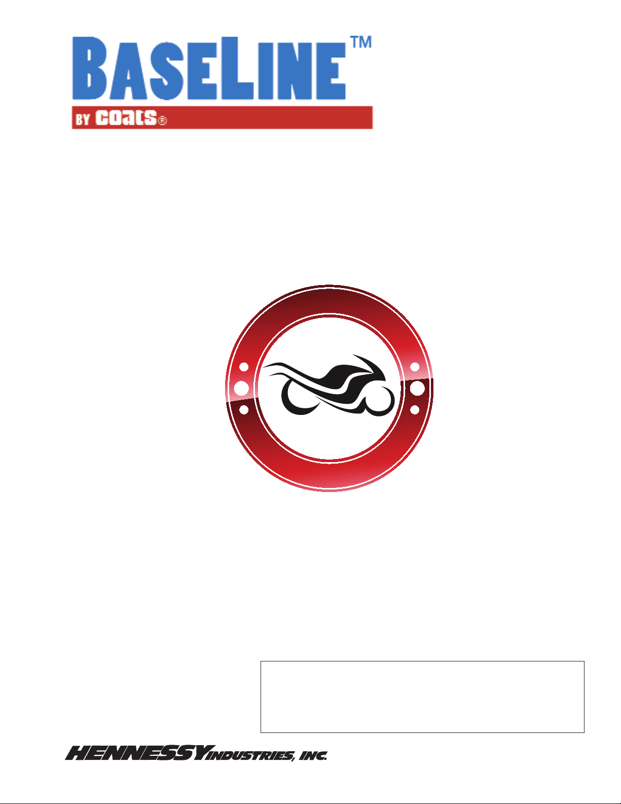
2. Pull the bead loosener shoe away from the machine
and roll wheel into position. The valve stem should be in
the 3 o’clock position. Position the bead loosener shoe
against the tire next to, but not on, the rim. Depress the
bead loosener foot pedal to actuate the shoe and loosen
the bead. It may be necessary to loosen the bead in
multiple locations around the tire (Figure 2).
Motorcycle
Figure 2 - Position Tire and Bead Loosener Shoe
3. Turn wheel around and repeat loosening procedure
on the other side of the wheel. This should be the long
side of the drop center.
ATV
TIP: It will be easier to clamp the wheel to the table
top if the lower bead is loosened last.
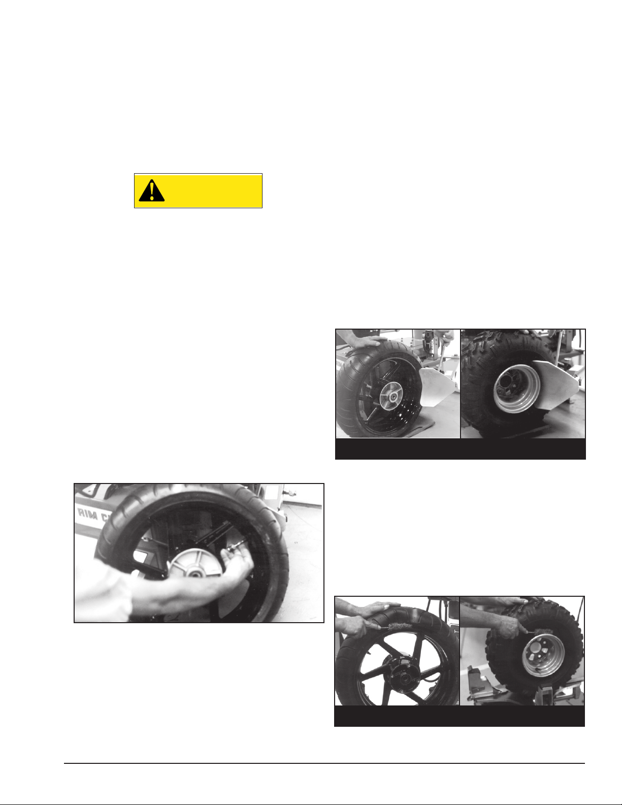
4. Apply tire manufacturer’s approved rubber lubricant
liberally to entire circumference of both tire beads after
loosening.
Figure 1 - Remove Valve Core to Deflate Tire
NOTE: Loosening the beads on a fully inflated tire
is unsafe and causes excess movement and friction
against the bumper pads and excessive wear on pivots.
Deflate the tire completely to prolong the life of your
machine.
ATV NOTE: It may be necessary on ATV wheels to
leave 3-6 PSI in some of these wheels to facilitate bead
loosening. Even after loosening one bead; it may be
Motorcycle
Figure 3 - Apply Rubber Lubricant to Tire Beads
ATV
BaseLine • 3
Page 4

5a. Prior to placing the wheel on the table top to
Motorcycle
ATV
Motorcycle
ATV
clamp, observe the style and strength of the wheel
and adjust the clamp pressure as necessary using the
pressure regulator and gauge. Thin spun aluminum rims
sometimes used on ATV and motorcycle are sometimes delicate and a reduced air pressure should be
considered verses cast aluminum and steel wheels that
can support more clamping force.
5b. Next, observe the rim size from the tire, i.e. 15,
16, 17, etc. Using the clamp pedal, place the clamp valve
in the JOG IN position for prelocating the clamps to
the rim diameter. Accomplish this by moving the pedal
from the UP position to the 1/2-DOWN location. Then
JOG the pedal DOWN allowing the clamps to move
inward until the pointer on the clamps align with the rim
diameter on the table top decal. It may be necessary to
relocate the clamps on the clamp carriers. Each clamp
should be in the same position before prelocating the
clamps.
5c. Determine the mounting side of the wheel. The
mounting side is the narrow side of the drop center.
(Tire removed in Figure 4 for clarity.)
Narrow Side
Drop Center
7. Move the swing arm into position. Pull the locking handle forward to release the slide. Push down
on the top of the vertical slide to move the demount
tool into contact with the
rim edge. Push the locking handle back to lock the
slide into place. As the
slide is locked, the mount/
demount tool will move
upward approximately 1/8
inch from the rim edge.
Note: On plastic mount/
demount tool, the upward
movement should be
limited to 1/16-inch maximum.
Figure 6 - Position Mount/Demount Tool
8. The mount/demount tool roller should be in contact
with the rim edge. Turn the swing arm adjusting knob
to move the tool away from the rim 1/8 to 1/4 inch.
On expensive and polished rims, it is recommended a
plastic bootie (p/n 8183373) be used over the mount/
demount tool roller.
Long Side
Motorcycle
Figure 4 - Determining Mounting Side of Wheel
ATV
6. Place tire/wheel assembly on table top with mounting side up (Figure 5). Use the clamp control pedal to
move the clamps inwards (push pedal down) or outwards (toggle pedal up). Clamp motorcycle and ATV
wheels from the outside (clamps push inwards against
the outside rim edge). Place rim flange into rear clamp
and slowly move the other clamps inward until they
contact the rim. Observe closely to prevent tire/wheel
damage.
Figure 7 - Adjust Swing Arm to Position Tool Roller
9. Check tool positioning. Mount/demount tool should
be positioned with 1/8 to 3/16” clearance between the
top of the rim edge and the bottom of the tool (with
plastic mount/demount tool it is recommended the vertical clearance be limited to a maximum of 1/16-inch),
and 1/8 to 1/4 inch clearance between the rim edge and
the tool. This clearance will be maintained as long as the
locking handle and adjustment knob are not changed.
The operator may swing the arm out of the way and
back into place again without needing to reposition the
tool (when changing a set of the same wheels).
Motorcycle
Figure 5 - Place Tire/Wheel Assembly on Table Top
ATV
4 • BaseLine
Page 5

NOTE: Push down on the tire across from the demount
Motorcycle
ATV
Motorcycle
ATV
Motorcycle
ATV
tool during table top rotation to utilize the drop center
area of the wheel. This reduces the tensional force on
the bead during demount.
1/8" to 3/16"
1/8" to 1/4"
Figure 8 - Proper Mount/Demount Tool Position
IMPORTANT: The vertical tool clearance may change
with machine use and should be inspected often. Failure to maintain the proper clearance may result in damage to the wheel rim and/or tire.
10. Insert the smooth curved end of the bead lifting tool over the forward end of the demount tool and
below the top bead of the tire. Use your free hand to
press down on the tire opposite the tool to help with
tool insertion (Figure 9).
13. Lift and hold the tire at an angle so that the lower
bead is resting in the drop center directly across from
the demount tool, and is loose below the demount tool
(Figure 11). Insert the smooth curved end of the bead
lifting tool down over the forward end of the mount/
demount tool and below the lower bead. Lift the bead
up and over the knob on the demount tool (Figure 11).
Motorcycle
Figure 11 - Demounting Lower Bead
14. Depress the table top pedal to rotate the wheel.
The demount tool will guide the bead up and over the
edge of the wheel. Continue rotation until lower bead
is demounted.
ATV
Motorcycle
Figure 9 - Insert Bead Lifting Tool
11. Rotate the bead lifting tool down towards the
wheel to lift the tire bead up and over the knob portion
of the demount tool. The tool may be removed if desired
(Figure 10).
Motorcycle
Figure 10 - Lift Bead Over Demount Tool
12. Depress the table top pedal to rotate the wheel
clockwise. The demount tool will guide the upper bead
up and over the edge of the wheel.
ATV
ATV
NOTE: With tube-type tires, demount the upper bead
and remove the tube before demounting the lower
bead.
NOTE: Table top rotation can be stopped at any time
by removing your foot from the pedal.
NOTE: Normal table top rotation for demounting is
clockwise. Depress the table top pedal to rotate this
direction. To rotate the table top counterclockwise, lift
the pedal up with your toe.
CAUTION
At times during the mounting and demounting procedure, the bead lifting tool may
encounter resistance or come under load.
Keep one hand firmly on the tool to avoid
possible tool disconnect. Use the reversing
feature to back out or jam ups.
BaseLine • 5
Page 6

Tire Mounting
Motorcycle
ATV
Motorcycle
ATV
This information must be read and followed carefully
to prevent accidents and injuries during mounting.
WARNING
Check tire and wheel carefully before
mounting. Make sure the tire bead diameter
and wheel diameter match exactly. Consult the Rubber Manufacturer’s Association
for approved rim widths for tire sizes. Mismatched tires and wheels explode.
CAUTION
2. Inspect tire for damage, paying close attention to
the beads. Verify size match between tire and wheel
(Figure 12).
3. Lubricate tire beads liberally with tire manufacturer
approved lubricant (Figure 13).
Never Mount a tire and wheel handed to
you by anyone without checking both tire
and wheel for damage and compatibility. Be
extra cautious of persons without knowledge of tire service. Keep by-standers out of
service area.
WARNING
Never mount a damaged tire. Never mount a
tire on a rusty or damaged wheel. Damaged
tires and/or wheels may explode.
CAUTION
If you damage the tire bead during mounting, STOP!, remove the tire and mark it as
damaged. Do not mount a damaged tire.
1. Inspect the wheel closely for damage. Clean the
wheel and remove any light corrosion or rubber residue
(Figure 12). Do not attempt to service heavily corroded
wheels.
Figure 13 - Lubricate Beads
4. Place tire over wheel and move swing arm into
position. Position the tire so that the lower bead is
above the rear extension of the mount/demount tool
and below the front knob (Figure 14).
Motorcycle
Figure 14 - Position Tire Against Mount/Demount Tool
5. Depress table top pedal and rotate the wheel to
mount the lower bead. Use the drop center of the wheel
to reduce the tensional force on the bead by pressing
down on the tire directly across from the mount tool.
Rotate table top until lower bead is fully mounted.
6. For top bead, rotate the table top until the valve
stem is directly across from the mount tool. Lift the
upper bead up and over the rear of the mount tool.
With your left hand press down on the tire between the
mount tool and the valve stem to hold the tire in the
drop center. Depress the table top pedal and rotate the
tire until the bead is mounted. Continue to press down
on the tire during the remaining mounting process.
ATV
Motorcycle
Figure 12 - Inspect and Clean the Wheel
ATV
6 • BaseLine
Page 7

WARNING
Do not force the tire onto the rim. Bead damage could result making the tire unsafe and/
or creating the risk of injury.
NOTE: If table top rotation stalls, reverse the table top
momentarily until the tire bead is again loose on the
wheel. Reposition the mount tool, make sure the bead
is correctly positioned in the drop center of the wheel,
then attempt mounting again.
NOTE: For low profile or stiff sidewall tires, it may be
advantageous to use the bead lifting tool to initially hold
the upper bead down in the drop center, or use drop
center tools.
NOTE: For tube type tires, mount the lower bead first,
move swing arm out, install the tube, and then mount
the upper bead.
BaseLine • 7
Page 8

85608968 00 07/13 © Copyright 2013 Hennessy Industries and COATS All Rights Reserved
 Loading...