


Model 225
Wheel Balancer
See
ÌBalancing Your
First Tire on page 5.
Safety Instructions
Setup Instructions
Operation Instructions
Maintenance Instructions
READ these instructions before placing unit in service. KEEP these and other materials delivered with the unit in a binder near the machine for ease of reference by supervisors and operators.
Manual Part No.: 85607560 01
Revision: 04/11

IMPORTANT SAFETY INSTRUCTIONS
READ ALL INSTRUCTIONS
1.Eye and face protection recommendations:
“Protective eye and face equipment is required to be used where there is a reasonable probability of injury that can be prevented by the use of such equipment.” O.S.H.A. 1910.133(a) Protective goggles, safety glasses, or a face shield must be provided by the owner and worn by the operator of the equipment. Care should be taken to see that all eye and face safety precautions are followed by the operator. ALWAYS WEAR SAFETY GLASSES. Everyday glasses only have impact resistant lenses, they are not safety glasses.
2.Do not disable hood safety interlock system, or in any way shortcut safety controls and operations.
3.Be sure that wheels are mounted properly, the hub nut engages the arbor for not less than four
(4)turns, and the hub nut is firmly tightened before spinning the wheel.
10.Wear proper clothing. Safety toe, non-slip footwear and protective hair covering to contain hair is recommended. Do not wear jewelry, loose clothing, neckties, or gloves when operating the balancer.
11.Keep work area clean and well lighted. Cluttered and/or dark areas invite accidents.
12.Avoid dangerous environments. Do not use power tools or electrical equipment in damp or wet locations, or expose them to rain.
13.Avoid unintentional starting. Be sure the balancer is turned off and power disconnected before servicing.
14.Disconnect the balancer before servicing.
15.Use only manufacturer’s recommended accessories. Improper accessories may result in personal injury or property damage.
4.Read and understand this manual before operat16. Repair or replace any part that is damaged or worn
ing. Abuse and misuse will shorten the functional life.
5.Be sure the balancer is properly connected to the power supply and electrically grounded.
6.Do not operate equipment with a damaged cord or if the equipment has been dropped or damaged – until it has been examined and repaired by a qualified serviceman.
7.Do not let cord hang over edge of table, bench, or counter or come in contact with hot manifolds or moving fan blades.
8.If an extension cord is necessary, a cord with a current rating equal to or more than that of the equipment should be used. Cords rated for less current than the equipment may overheat. Care should be taken to arrange the cord so that it will not be tripped over or pulled.
9.Keep guards and safety features in place and in working order.
and that may cause unsafe balancer operation. Do not operate damaged equipment until it has been examined by a qualified service technician.
17.Never overload or stand on the weight tray or any part of the balancer.
18.Do not allow untrained persons to operate machinery.
19.To reduce the risk of fire, do not operate equipment in the vicinity of open containers or flammable liquids (gasoline).
20.Adequate ventilation should be provided when working on or operating internal combustion engines.
21.Keep hair, loose clothing, fingers, and all parts of body away from moving parts.
22.Use equipment only as described in this manual.
23.Use only manufacturer’s recommended attachments and accessories.
SAVE THESE INSTRUCTIONS
ii • |
Important: Always read and follow instructions. |

Owner’s Responsibility
To maintain machine and user safety, the responsibility of the owner is to read and follow these instructions:
•Follow all installation instructions.
•Make sure installation conforms to all applicable Local, State, and Federal Codes, Rules, and Regulations; such as State and Federal OSHA Regulations and Electrical Codes.
•Carefully check the unit for correct initial function.
•Read and follow the safety instructions. Keep them readily available for machine operators.
•Make certain all operators are properly trained, know how to safely and correctly operate the unit, and are properly supervised.
•Allow unit operation only with all parts in place and operating safely.
•Carefully inspect the unit on a regular basis and perform all maintenance as required.
•Service and maintain the unit only with authorized or approved replacement parts.
•Keep all instructions permanently with the unit and all decals/labels/notices on the unit clean and visible.
•Do not override safety features.
Operator Protective Equipment
Personal protective equipment helps make tire servicing safer. However, equipment does not take the place of safe operating practices. Always wear durable work clothing during tire service activity. Loose fitting clothing should be avoided. Tight fitting leather gloves are recommended to protect operator’s hands when handling worn tires and wheels. Sturdy leather work shoes with steel toes and oil resistant soles should be used by tire service personnel to help prevent injury in typical shop activities. Eye protection is essential during tire service activity. Safety glasses with side shields, goggles, or face shields are acceptable. Back belts provide support during lifting activities and are also helpful in providing operator protection. Consideration should also be given to the use of hearing protection if tire service activity is performed in an enclosed area, or if noise levels are high.
Definitions of Hazard Levels
Identify the hazard levels used in this manual with the following definitions and signal words:
DANGER
Watch for this symbol:

 DANGER
It Means: Immediate hazards, which will result in severe personal injury or death.
WARNING
Watch for this symbol:

 WARNING
It Means: Hazards or unsafe practices, which could result in severe personal injury or death.
CAUTION
Watch for this symbol:

 CAUTION
It Means: Hazards or unsafe practices, which may result in minor personal injury or product or property damage.
Watch for this symbol! It means BE ALERT! Your safety, or the safety of others, is involved!
Important: Always read and follow instructions. |
• iii |

Safety Notices and Decals

 WARNING
Failure to follow danger, warning, and caution instructions may lead to serious personal injury or death to operator or bystander or damage to property. Do not operate this machine until you read and understand all the dangers, warnings and cautions in this manual. For additional copies of either, or further information, contact:
Hennessy Industries, Inc.
1601 JP Hennessy Drive
LaVergne, TN 37086-3565
(615)641-7533 or (800) 688-6359 www.ammcoats.com
Standard Safety Devices
•A hood guard of high impact plastic that is designed to prevent the counterweights from flying out in any direction except towards the floor.
•A hood switch interlock system that prevents the machine from starting if the guard is not lowered and stops the wheel whenever the guard is raised.
iv • |
Important: Always read and follow instructions. |
Table of Contents |
|
Important Safety Instructions ................................. |
ii |
Owner’s Responsibility............................................ |
iii |
Operator Protective Equipment............................... |
iii |
Definitions of Hazard Levels.................................... |
iii |
Safety Notices and Decals ...................................... |
iv |
Standard Safety Devices ......................................... |
iv |
Setup Instructions ............................................... |
2 - 3 |
Receiving................................................................. |
2 |
Unpacking the Unit.................................................. |
2 |
Remove Balancer from Pallet .................................. |
2 |
Floor and Space Requirements ............................... |
2 |
Electrical Requirements .......................................... |
2 |
Wheel Guard Installation ......................................... |
3 |
Connect to Power.................................................... |
3 |
Initial Testing............................................................ |
3 |
Specifications............................................................ |
4 |
Accessory Options.................................................... |
4 |
Features..................................................................... |
4 |
Balancing Your First Tire ........................................... |
5 |
Principle Operating Parts .................................... |
6 - 7 |
Know Your Unit ........................................................ |
6 |
Power Switch........................................................... |
6 |
Using The Offset Arm.............................................. |
7 |
Control Panel ........................................................... |
7 |
Rounding ................................................................. |
7 |
Ounce/Gram............................................................ |
7 |
Wheel Guard ........................................................... |
7 |
Brake Pedal.............................................................. |
7 |
Auto Stop Feature ................................................... |
7 |
Mounting Wheel on Spindle Shaft..................... |
8 - 9 |
Standard Back Cone Mounting................................ |
8 |
Standard Front Cone Mounting ............................... |
9 |
Setting Wheel Dimensions (DIM) .................... |
10 - 11 |
Definition of DIM.................................................... |
10 |
Wheel Data Entry (W, D, A).................................... |
11 |
Balancing Programs ........................................ |
12 - 13 |
Dynamic Balancing ................................................ |
12 |
Static Balancing..................................................... |
12 |
Aluminium Wheel .................................................. |
13 |
Attaching Corrective Weights ................................ |
14 |
Match Balance (Optimization)........................ |
14 - 15 |
Match Balance Program ........................................ |
14 |
Quick OPT Program............................................... |
15 |
Calibration Program ............................................... |
16 |
First Sensitivity Calibration .................................... |
16 |
Second Sensitivity Calibration ............................... |
16 |
Diagnostic Procedures ........................................... |
17 |
After Balance Vibration Problems ........................... |
17 |
Balancing Accessory Availability Status.................. |
17 |
Troubleshooting...................................................... |
18 |
Error Display .......................................................... |
19 |
Maintenance Instructions ...................................... |
20 |
Glossary Of Terms................................................... |
21 |
NOTICE
Read entire manual before assembling, installing, operating, or servicing this equipment.
Important: Always read and follow instructions. |
• 1 |
Setup Instructions
Receiving
The shipment should be thoroughly inspected as soon as it is received. The signed bill of lading is acknowledgement, for the carrier, of receipt in good condition of the shipment covered by our invoice.
If any of the goods called for on this bill of lading are shorted or damaged, do not accept them until the carrier makes a notation of the shorted or damaged goods on the freight bill. Do this for your own protection.
NOTIFY THE CARRIER AT ONCE if any hidden loss or damage is discovered after receipt and request him to make an inspection. If the carrier will not do so, prepare an affidavit to the effect that you have so notified the carrier (on a certain date) and that he has failed to comply with your request.
IT IS DIFFICULT TO COLLECT FOR LOSS OR DAMAGE AFTER YOU HAVE GIVEN THE CARRIER A CLEAR RECEIPT.
File your claim with the carrier promptly. Support your claim with copies of the bill of lading, freight bill, invoice, and photographs, if possible.
Unpacking the Unit
•Remove the shipping carton from the pallet.
•Remove all loose parts and accessories packed around the unit.
Remove Balancer from Pallet
1. Remove the shipping bolts that hold the balancer to the pallet.

 CAUTION
Do not use the control panel, control panel base, accessory storage, faceplate, hood or shaft to lift the balancer.

 CAUTION
Use help to remove the balancer from the pallet. The unit is heavy and the weight is not evenly distributed. Dropping the unit may cause personal injury or equipment damage.
2. Lift the balancer off the pallet and place it in its operating location.
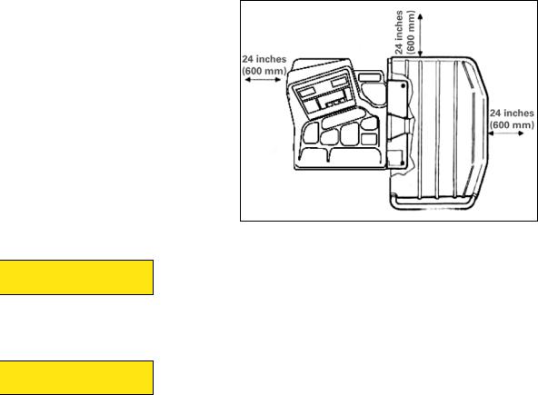
Floor and Space Requirements
The balancer must be located on a flat floor of solid construction, preferably concrete. The balancer must sit solidly on its three feet. If the balancer is not level, does not sit solidly on its three feet, or is placed on an unstable floor, the balancer will not function properly and may produce inaccurate balance readings.
Do not operate the balancer while it is on the pallet.
Select a location for the balancer that provides a level, solid floor, and adequate clearance around and above the balancer. Make sure the location selected has enough room above and behind the unit so the hood can be raised completely. The location must also provide working room for mounting and removing wheels. Make sure the area has adequate lighting.
Figure 1 - Space Requirements
Electrical Requirements
See serial tag for the appropriate power requirements of your machine.
Always have a qualified electrician install the proper receptacles in accordance with state and local codes.
2 • |
Important: Always read and follow instructions. |

Wheel Guard Installation
1.Unscrew the nuts that lock the two bolts on the wheel guard support pin holes and take out the bolts.
2.Fit the wheel guard tube into the support pin, lining up the two sets of holes.
3.Fit the two bolts into the holes and attach the wheel guard on to the support by tightening up the nuts.
Connect to Power
Your factory trained COATS® ServiceTechnician should do the final check to verify the power installation before connecting the balancer to a power supply. Failure due to improper power connection may void the warranty.
Initial Testing
1.Plug the unit into an appropriate power outlet. If the circuit breaker for the outlet is off, turn it on.
2.Turn the balancer on. The power switch is on the back of the unit.
Figure 2 - Install Wheel Guard Onto Balancer
Important: Always read and follow instructions. |
• 3 |
Specifications
Wheel Diameter Range
8 - 23 inches (203 - 584 mm)
Wheel Width Range
1.5 - 20 inches (40 - 510 mm)
Maximum Outside Tire Diameter
Up to 35 inches (900 mm)
Maximum Tire/Wheel Weight
100 pounds (45.4 Kg)
Mounting Shaft Diameter
40 mm
Resolution (Round Off Mode)
0.25 ounce, position 1.40 degrees
Resolution (Non-Round Off Mode)
0.10 ounce, position 1.40 degrees
Balancing Display Increments
0.25 or 0.10 ounces
Electrical Requirements
115 V, 1 Ph, 5 amp 230V, 1Ph, 2.5 amp
(use grounding type plug)
Footprint
43 x 39 inches (1090 x 980 mm)
Shipping Weight
251 pounds (114 Kg) (without accessories)
Standard Accessories
•8112107 Cone Spring
•8112098 Small Cone
•8112099 Medium Cone
•8112100 Large Cone
•8112106 Small Pressure Drum with Ring
•8113175 Wheel Weight Hammer
•8112103 Hub Nut
•8309011 Caliper
Features
•Integrated LED touch panel display
•8 balancing modes, including dynamic clip, static, match, and 5 tape-a-weight™ options
•Positioning foot pedal system to hold assembly in place while placing weights
•Space-saving design
•Access to COATS® extensive Factory Authorized service network
•6 months Parts Warranty
4 • |
Important: Always read and follow instructions. |
ÌBalancing Your First Tire
1.Turn the machine OFF then ON (resets machine).
Note: The machine wakes up using standard clip-on wheel weight locations (C1 & C2) and wheel dimensions.
2.Mount a tire/wheel on the balancer that will use standard clip-on wheel weights.
Use the most appropriate mounting method.
3.Always remove any weights already attached to the wheel.
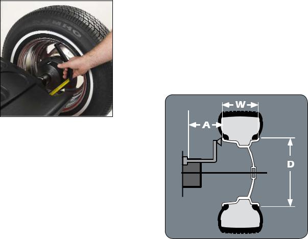
4.Enter A & D wheel dimensions using offset arm.
7.Raise hood after tire stops rotating.
Note: Wait for wheel to stop before raising the hood.
8.Rotate wheel to inboard (left plane) position of unbalance.
9.Attach inboard (left plane) corrective weight.
Attach specified weight amount at top-dead- center on inside flange of wheel.
10.Rotate wheel to outboard (right plane) position of unbalance.
11.Attach outboard (right plane) corrective weight.
Attach specified weight amount at top-dead- center on outside flange of wheel.
12.Lower the hood to respin the tire/wheel and check balance.
Your weight readings should now be 0.00.
Note: Throughout this manual tire dimensions are referred to as A, W, and D, see figure 4.
Figure 3 - Offset Arm At Clip-On Weight Location
5. Enter Width wheel dimension.
Use plastic calipers to measure wheel width from wheel flange to wheel flange. Use keypad to enter Width value.
6.Lower the hood, press Start; wheel spins and unbalances are
measured and displayed.
After the beep signal, the corrective weight amount appears in the digital readout windows.
Figure 4 - A, W, and D Tire Dimensions
Important: Always read and follow instructions. |
• 5 |
 Loading...