

Page 1
1
6,000 lb. ( 2721 kg ) Portable MID RISE
READ the Manual Thoroughly Before Installing,
Operating, Servicing, or Maintaining the Lift
SAVE this MANUAL and ALL INSTRUCTIONS
Model: BLMR06
1601 J.P. Hennessy Drive
La Vergne, TN 37086
Tel. (800) 688-6359
Page 2

2
Lift Purchase Buyers Agreement
Warranty
Each product comes with a two (2) year parts warranty with five (5) years warranty on the
structure. The parts warranty is limited to defects in workmanship and material. The warranty
does not cover misuse, abuse, overloading, lack of maintenance, and inappropriate use or
“normal wear and tear”. Warranty parts must be returned to manufacturer for inspection to
qualify for warranty. Shipping costs are the owner’s responsibility.
Freight Damage
Each lifting product is carefully inspected before being loaded by our shipping department. Any
damage to the product must be noted on the shipping companies “bill of lading” and signed by
the driver. It is the owner’s responsibility to advice manufacturer within 48 business hours, of
any shipping damage.
Installation
At the purchase request, delivery and installation can be arranged by a professional contractor.
It is the owner’s responsibility to approve the completion of the work done and that the product
is working properly. If there is a dispute with the work being done the owner must advise our
office within 24 business hours.
Lift Maintenance
Every lifting product will require ongoing adjustment and maintenance. It is normal that the lifting
cables will require adjustment to ensure that the lift operates level. Periodic adjustments are the
owner’s responsibility. If the owner requires the assistance of a lift technician, a service charge
will be paid directly for a service call. The lift is manufactured with a baked on power coat finish.
It is recommended to maintain this finish that scratches are periodically touched up with
automotive style paint. All non-painted services should be kept clean and lubricated to prevent
rust or corrosion.
Service Calls
Onsite service of your lifting product can be arranged by a qualified lift service technician. The
owner will be responsible for paying the contractor directly for this service at the time the work is
completed. It is the owner’s responsibility to return any parts to manufacturer for warranty
consideration.
Page 3

3
Your new lift will provide years of dependable service if installed, operated and maintained
properly. Read and follow all safety, installation, operation, and maintenance instructions in this
manual before installing and operating the lift. In addition, read and follow all safety and other
information included on and with the lift before operating the lift. Keep this manual in a secure
place for future reference, training and service part identification.
TABLE of CONTENTS
1. Unloading Procedure & Lift Package Contents page 4
2. Important Safety Instructions page 5
3. General Requirements & Lift Specifications page 7
4. Installation And Operation Instructions page 8
5. Troubleshooting page 20
6. Lift Installation Diagrams & Parts Lists page 22
IMPORTANT: It is the shop owner's responsibility to provide a satisfactory installation area
for the lift. Lifts should only be installed indoors on level concrete floors with a minimum of 4
inches (102mm) and 3000 psi (20.7MPa) concrete that has been aged a minimum of 30 days.
Please consult a qualified individual if any doubt exists concerning proper installation and
subsequent safe operation of the lift. Do not install the lift on asphalt or outdoors.
Prior to installation, it is the shop owner's responsibility to provide constant electrical power in
the correct voltage, phase, etc., and all wiring for electrical hook-up of the lift. The shop owner
must insure that the electrical installation conforms to local building and safety codes. Where
required, the shop owner will provide an electrical isolation switch located in close proximity to
the lift. This switch will have an emergency stop capability and isolate electrical power from the
lift for servicing requirements.
Hydraulic oil cannot be shipped with the lift and will be supplied by either the shop owner or the
installer. ISO 32 hydraulic oil (10W non detergent hydraulic oil) must be used to fill the
reservoir tank before operating the lift.
It is the shop owner's responsibility to train all operators in lift
operation and safety.
Page 4

4
1. UNLOADING PROCEDURE and LIFT PACKAGE CONTENTS
For your information:
All lift components are grouped together in one package held at each end by steel frames.
Unpacking Procedure:
When the lift arrives on site:
If possible have the lift unloaded in the installation area.
Check for freight damage and report immediately to the trucking company who delivered
the lift.
Check for missing parts and report immediately to the factory.
Main Components include:
Lift Assembly – 1pc
Powerpack Assembly – 1 pc
Accessory and Hardware Box includes:
Rubber Stack Lifting Pad Assembly – 4 pc
Lifting Adapters – 4 pc
Extended Lifting Adapters – 4 pc
Hydraulic Hose w/ Fittings – 1pc
Hardware Box
Owner’s Manual
Page 5

5
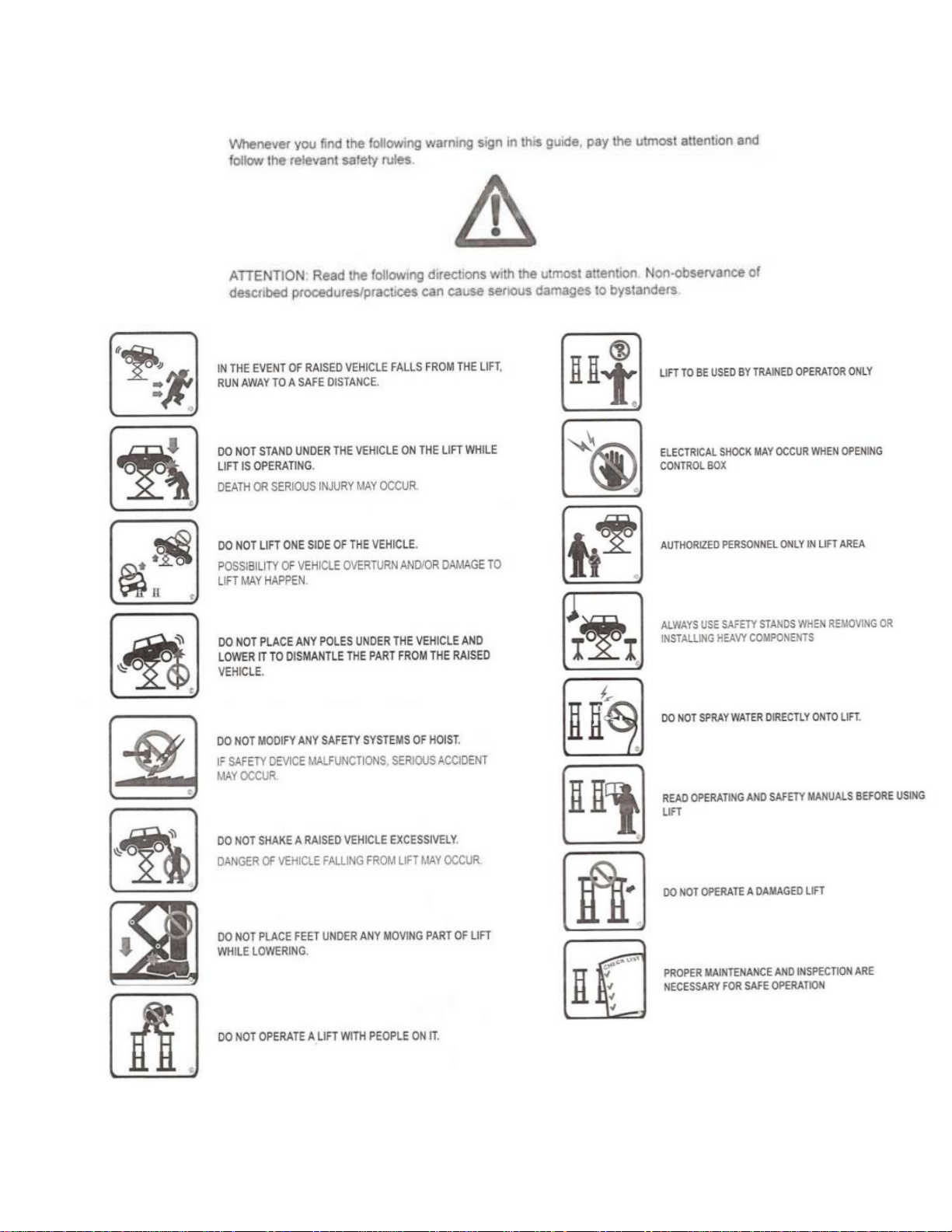
2. IMPORTANT SAFETY INSTRUCTIONS
When using your garage equipment, basic safety precautions should always be followed,
including the following:
1. Read all instructions
2. Do not operate equipment with a damaged cord or if equipment has been dropped or
damaged – until it has been examined by a qualified service person
3. To reduce risk of fire, do not operate equipment in the vicinity of open containers of
flammable liquids (gasoline)
4. Adequate ventilation should be provided when working on operating internal combustion
engines
5. Keep hair, loose clothing, fingers, and all parts of body away from moving parts
6. To reduce the risk of electric shock, do not use on wet surfaces or expose to rain
7. Use only as directed in this manual. Use only manufacturer’s recommended attachments
8. ALWAYS WEAR SAFETY GLASSES. Everyday eyeglasses only have impact resistant lenses,
they are not safety glasses
Basic common sense safety precautions should always be followed when installing, operating
and maintaining the lift as a risk of fire, electric shock, injury or death may be present.
In addition:
1. Only trained and authorized personnel should position a vehicle and operate the lift.
2. Inspect the lift daily. Do not operate if potential problems have been identified or lift
malfunctions. Do not operate if lift has damaged or broken components. Never walk or
work under the lift unless all safety locks are completely engaged.
3. Never overload the lift. The hydraulic system on this lift is not designed to be a load
holding device. Mechanical safety locks must be engaged before proceeding under the lift
for vehicle servicing or lift maintenance. Never override operating controls. This is unsafe
and will void the warranty.
4. Before driving a vehicle onto the lift, insure that the lift and lift area is clear of all debris
and that all oil and grease has been cleaned from runway surfaces.
5. Always chock wheels and set parking brake before lifting vehicle.
6. When using a jack(s) to raise a vehicle, position jack lifting pads to contact vehicle
manufacturers recommended lifting points. Raise jack slowly until all pads contact the
vehicle. Confirm that the vehicle is stable on the jack(s) before raising to desired working
height.
7. Important: Removal or installation of heavier parts can change the vehicle's center of
gravity on the jack(s) resulting in a critical load shift. The vehicle may then be unstable.
Plan ahead for this possibility to insure continued safety and refer to the vehicle
manufacturer’s service manual for recommended procedures.
8. Always keep the lift area free of obstructions and debris. Grease and oil spills should be
cleaned up immediately.
9. Never raise a vehicle on the lift with passengers inside. Before lowering, check the lift
Page 6

6
and lift area and remove all obstructions. Before removing vehicle from the lift or lift
area, confirm an unobstructed exit.
10. DO NOT PERFORM ANY MAINTENANCE OR INSTALLATION OF ANY COMPONENTS WITH
OUT FIRST ENSURING THAT ELECTRICAL POWER HAS BEEN DISCONNECTED AT THE
SOURCE OR PANEL AND CANNOT BE RE-ENERGIZED UNTIL ALL MAINTENANCE AND/OR
INSTALLATION PROCEDURES ARE COMPLETED (ANSI 244.1).
SAVE THESE INSTRUCTIONS
Page 7
7
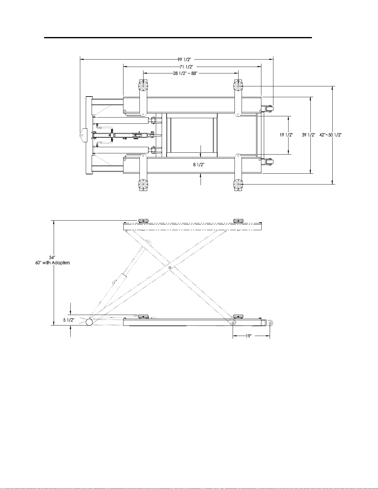
3. GENERAL REQUIREMENTS & LIFT SPECIFICATIONS
6,000 (2727 kg) Capacity – 1,500 lbs. Each Lifting Pad
Constant supply of 220V or 110V 1PH 60Hz 20A
electrical power is required for this lift.
Page 8
8
Page 9

9
Page 10

10
Page 11
11
Page 12

12
Page 13

13
Page 14
14
Page 15

15
Page 16

16
Page 17
17
Page 18
18
Page 19

19
Page 20

20
LIFT PROBLEM TROUBLESHOOTING GUIDE
Problem
Possible Causes
Solutions
Lift Will
Not Raise
or Lower
1. Blown fuse or circuit breaker
2. Incorrect voltage to motor
3. Bad wiring connections
4. "UP" switch burned out
5. Motor windings burned out
1. Replace fuse or reset/replace circuit breaker
2. Supply correct voltage to motor
3. Repair and insulate all connections
4. Replace switch
5. Replace motor
Lift Will
Not Raise
1. Air in oil or low oil level
2. Lowering Valve leaks
3. Motor runs backward
4. Pump damaged
5. Pump will not prime
6. Relief Valve leaks
7. Voltage to motor incorrect
8. Lift overloaded
1. Check fluid level, oil seal, bleed system
2. Clean valve or replace
3. Check for correct wiring
4. Repair of replace pump
5. Check fluid level and pick-up tube; replace
pump
6. Clean Relief Valve (replace if necessary)
7. Supply correct voltage to motor
8. Verify that loaded vehicle weight does not
exceed rated lift capacity
Lift Will
Not Lower
1. Mechanical locks are engaged
2. Obstruction under lift or in glide
block tracks
3. Faulty lowering valve
1. Raise unit slightly and disengage mechanical
locks
2. Carefully remove obstruction - clean glide block
tracks
3. Replace valve
Lift Will
Not Hold
Pressure
1. Contamination in system
2. Internal Cylinder leaks
3. Lowering Valve leaks
4. Check Valve leaks
5. External leaks
1. Check oil level, bleed cylinders, remove
Contamination, replace oil seal
2. Check fitting, replace cylinder
3. Contaminated fluid, handle binds, clean valves
4. Clean check valve (replace if necessary)
5. Check all fittings and repair leaks
Lift Will
Not Raise
A Vehicle
1. Low hydraulic fluid
2.Malfunction of pressure relief valve
3. Insufficient electrical voltage
4. Lift overload
5. Motor is running backwards
6. Air in hydraulic oil
7. Pump will not prime
8. Pump is damaged
9. Faulty lowering valve
1. Lower lift. Using ISO grade 32 hydraulic oil, fill
the powerpack reservoir to 1" below the top
2. Clean pressure relief valve. if problem
continues, call a service technician
3. Confirm a 208/230 volt power supply to the lift
4. Check that vehicle weight is evenly distributed
And does not exceed rated capacity.
5. Confirm proper motor rotation - rewire if
required
6. Check oil seal and bleed hydraulic system
7. Check hydraulic oil level and pick-up tube.
Replace pump if required
8. Repair or replace pump
9. Clean or replace valve
The following are some suggestions to consider if problems are encountered with the lift. Please
call a Trained Lift Service Person for further clarification and information.
Page 21

21
Problem
Possible Causes
Solutions
Slow Drift
Down
1. Mechanical safety locks not
engaged
2. Powerpack lowering valve
contamination
3. Hydraulic system leaks
1. Raise lift to engage all safety locks then lower
lift and confirm all safety locks are engaged
2. Back flush powerpack by opening manual
over-right valve. Engage "up" switch and down
lever at the same time and run approximately
10 seconds
3. Check cylinder and all fittings for any hydraulic
oil leak
Replace all worn or broken parts and components only with
manufacturer approved/supplied parts and components
Replacement parts may be purchased from your local lift supplier or the
manufacturer at 1 - 800 - 688 - 6359
Page 22
22
for installation & service part reference
SAVE this MANUAL and ALL INSTRUCTIONS
6,000 lb. ( 2721 kg ) Portable MID RISE
Model: BLMR06
1601 J.P. Hennessy Drive
La Vergne, TN 37086
Tel. (800) 688-6359
Page 23

23
Page 24

24
 Loading...