

Page 1
1
Issue 01 Effective: Oct 1, 2013
READ the Manual Thoroughly Before Installing,
Operating, Servicing, or Maintaining the Lift
SAVE this MANUAL and ALL INSTRUCTIONS
12,000 lb. (5454 kg) Closed Front 4-Post Lifts
BL412 – 12,000lb 4 Post Lift
1601 J.P. Hennessy Drive
La Vergne, TN 37086
Tel. (800) 688-6359
Page 2

2
Lift Purchase Buyers Agreement
Warranty
Each product comes with a two (2) year parts warranty with five (5) years warranty on the
structure. The parts warranty is limited to defects in workmanship and material. The warranty
does not cover misuse, abuse, overloading, lack of maintenance, and inappropriate use or
“normal wear and tear”. Warranty parts must be returned to manufacturer for inspection to
qualify for warranty. Shipping costs are the owner’s responsibility.
Freight Damage
Each lifting product is carefully inspected before being loaded by our shipping department.
Any damage to the product must be noted on the shipping companies “bill of lading” and
signed by the driver. It is the owner’s responsibility to advice manufacturer within 48
business hours, of any shipping damage.
Installation
At the purchase request, delivery and installation can be arranged by a professional
contractor. It is the owner’s responsibility to approve the completion of the work done and
that the product is working properly. If there is a dispute with the work being done the
owner must advise our office within 24 business hours.
Lift Maintenance
Every lifting product will require ongoing adjustment and maintenance. It is normal that the
lifting cables will require adjustment to ensure that the lift operates level. Periodic
adjustments are the owner’s responsibility. If the owner requires the assistance of a lift
technician, a service charge will be paid directly for a service call. The lift is manufactured
with a baked on power coat finish. It is recommended to maintain this finish that scratches
are periodically touched up with automotive style paint. All non-painted services should be
kept clean and lubricated to prevent rust or corrosion.
Service Calls
Onsite service of your lifting product can be arranged by a qualified lift service technician.
The owner will be responsible for paying the contractor directly for this service at the time the
work is completed. It is the owner’s responsibility to return any parts to manufacturer for
warranty consideration.
Page 3

3
Your new lift will provide years of dependable service if installed, operated and maintained
properly. Read and follow all safety, installation, operation, and maintenance instructions in
this manual before installing and operating the lift. In addition, read and follow all safety and
other information included on and with the lift before operating the lift. Keep this manual in a
secure place for future reference, training and service part identification.
TABLE of CONTENTS
1. Unloading Procedure & Lift Package Contents page 4
2. Important Safety Instructions page 5
3. General Requirements & Lift Specifications page 7
4. Tools Required & Pre Installation Procedures page 8
5. Installation Procedures page 10
6. Operating Instructions & Lift Maintenance page 15
7. Troubleshooting page 21
8. Lift Installation Diagrams & Parts Lists page 24
IMPORTANT: It is the shop owner's responsibility to provide a satisfactory installation
area for the lift. Lifts should only be installed indoors on level concrete floors with a
minimum of 4 inches (102mm) and 3000 psi (20.7MPa) concrete that has been aged a
minimum of 30 days. Please consult a qualified individual if any doubt exists concerning
proper installation and subsequent safe operation of the lift. Do not install the lift on asphalt
or outdoors.
Prior to installation, it is the shop owner's responsibility to provide constant electrical power
in the correct voltage, phase, etc., and all wiring for electrical hook-up of the lift. The shop
owner must insure that the electrical installation conforms to local building and safety codes.
Where required, the shop owner will provide an electrical isolation switch located in close
proximity to the lift. This switch will have an emergency stop capability and isolate electrical
power from the lift for servicing requirements.
Hydraulic oil cannot be shipped with the lift and will be supplied by either the shop owner or
the installer. ISO 32 hydraulic oil (10W non detergent hydraulic oil) must be used to fill the
reservoir tank before operating the lift.
It is the shop owner's responsibility to train all operators in
lift operation and safety.
Page 4

4
1. UNLOADING PROCEDURE & LIFT PACKAGE CONTENTS
For your information:
All lift components are packaged together in one module held together by steel frames
Optional accessories (ex. rolling jacks) are packaged separately.
UNPACKING PROCEDURE:
When the lift arrives on site:
1. If possible have lift unloaded in the installation area and on two 4"x 4" x 24" Wooden
Blocks (required for unpacking).
2. Check for freight damage and report immediately to the trucking company who
delivered the lift.
3. Check for missing parts and report immediately to the factory 1-877-799-LIFT(5438)
or (289) 291-3335
Main Components include:
Columns – 4 pcs
Runway Assemblies – 2 pcs
Crossbeams – 2 pcs (1 front – 1 rear)
Powerpack – 1 pc
Accessories (see list below)
Accessory includes:
Lifting Cables – 2 pcs
Hydraulic Hose - 1 pc
Approach Ramps – 2 pcs
Wheel Stops – 2 pcs
Owner’s Manual – 1 copy
Hardware Box includes: Fittings, bolts, washers, nuts, shims, and anchor bolts, etc.
Page 5

5
2. IMPORTANT SAFETY INSTRUCTIONS
When using your garage equipment, basic safety precautions should always be followed,
including the following:
1. Read all instructions
2. Do not operate equipment with a damaged cord or if equipment has been dropped or
damaged – until it has been examined by a qualified service person
3. To reduce risk of fire, do not operate equipment in the vicinity of open containers of
flammable liquids (gasoline)
4. Adequate ventilation should be provided when working on operating internal combustion
engines
5. Keep hair, loose clothing, fingers, and all parts of body away from moving parts
6. To reduce the risk of electric shock, do not use on wet surfaces or expose to rain
7. Use only as directed in this manual. Use only manufacturer’s recommended attachments
8. ALWAYS WEAR SAFETY GLASSES. Everyday eyeglasses only have impact resistant
lenses, they are not safety glasses
Basic common sense safety precautions should always be followed when installing, operating
and maintaining the lift as a risk of fire, electric shock, injury or death may be present.
In addition:
1. Only trained and authorized personnel should position a vehicle and operate the lift.
2. Inspect the lift daily. Do not operate if potential problems have been identified or lift
malfunctions. Do not operate if lift has damaged or broken components. Never walk or
work under the lift unless all safety locks are completely engaged.
3. Never overload the lift. The hydraulic system on this lift is not designed to be a load
holding device. Mechanical safety locks must be engaged before proceeding under the lift
for vehicle servicing or lift maintenance. Never override operating controls. This is unsafe
and will void the warranty.
4. Before driving a vehicle onto the lift, insure that the lift and lift area is clear of all debris
and that all oil and grease has been cleaned from runway surfaces.
5. Always chock wheels and set parking brake before lifting vehicle.
6. When using a jack(s) to raise a vehicle, position jack lifting pads to contact vehicle
manufacturers recommended lifting points. Raise jack slowly until all pads contact the
vehicle. Confirm that the vehicle is stable on the jack(s) before raising to desired working
height.
7. Important: Removal or installation of heavier parts can change the vehicle's center of
gravity on the jack(s) resulting in a critical load shift. The vehicle may then be unstable.
Plan ahead for this possibility to insure continued safety and refer to the vehicle
manufacturer’s service manual for recommended procedures.
8. Always keep the lift area free of obstructions and debris. Grease and oil spills should be
cleaned up immediately.
9. Never raise a vehicle on the lift with passengers inside. Before lowering, check the lift
Page 6

6
and lift area and remove all obstructions. Before removing vehicle from the lift or lift
area, confirm an unobstructed exit.
10. DO NOT PERFORM ANY MAINTENANCE OR INSTALLATION OF ANY COMPONENTS WITH
OUT FIRST ENSURING THAT ELECTRICAL POWER HAS BEEN DISCONNECTED AT THE
SOURCE OR PANEL AND CANNOT BE RE-ENERGIZED UNTIL ALL MAINTENANCE AND/OR
INSTALLATION PROCEDURES ARE COMPLETED (ANSI 244.1).
SAVE THESE INSTRUCTIONS
Page 7
7
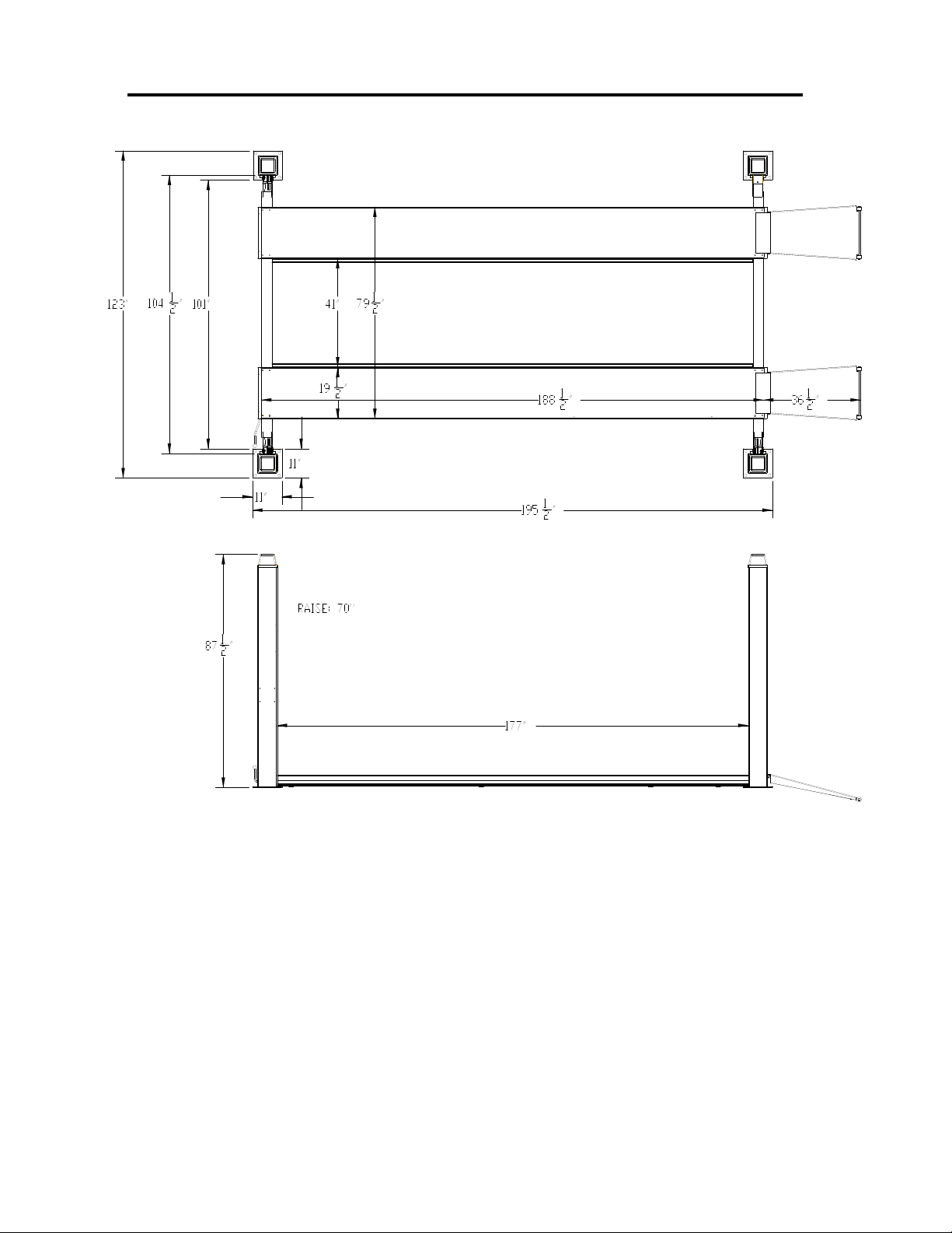
3. GENERAL REQUIREMENTS & LIFT SPECIFICATIONS
12,000 lb. (5454 kg) Capacity - 6,000 lbs. (2727 kg) each Runway
constant supply of 230V 1PH 60Hz 20A electrical power is required for this lift.
Page 8

8
4. TOOLS REQUIRED & PRE INSTALLATION PROCEDURES
TOOLS REQUIRED
30ft. measuring tape, chalk line and chalk, 2 x 4 ft. level (laser level also suggested)
Wooden blocks, Step Ladder
Work stands - 4 (runway set-up and installation)
Metric and SAE wrenches sets, ratchet sets and Allen key sets
Crow bar, hammer and screwdrivers
Rotary hammer drill c/w ¾ inch diameter masonry drill bit
Hydraulic Oil (ISO 32)
PRE-INSTALLATION PROCEDURE
Before proceeding with installation, read the installation manual and insure all instructions are fully
understood and all component parts listed on page 3 are accounted for.
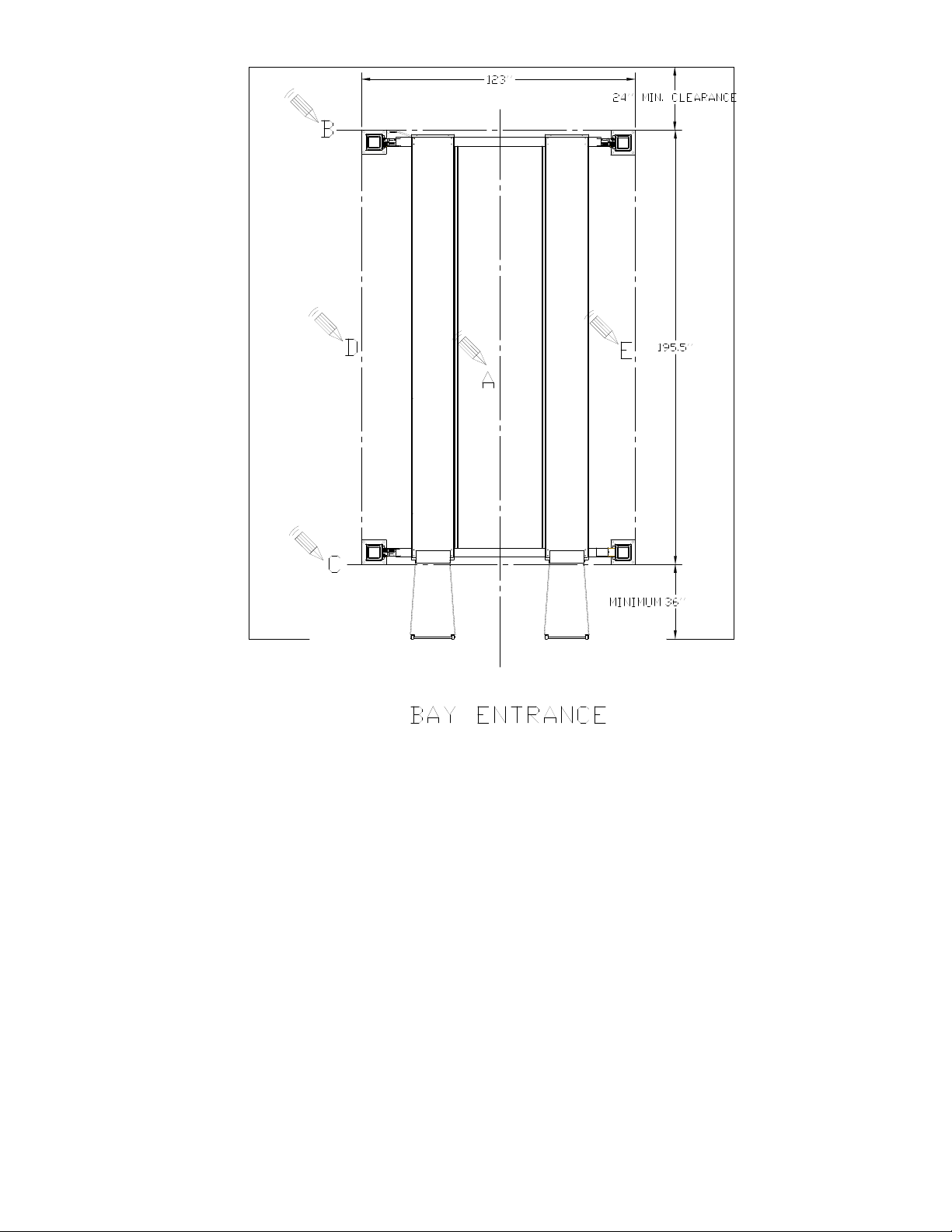
Identify bay center line near the front and mark the floor. Also mark center of the bay entrance.
Connect these two points with a chalk line "A". Refer to diagram on the next page for minimum
clearance from bay entrance door and draw a second chalk line "C" at 90° to the centerline.
Measure 195.5’’ from line “C” and mark front baseplate line “B”. Make sure “B” is perpendicular to
“A”. Refer to diagram and mark line “D” and “E”. Line “B”, “C”, “D” and “E” are baseplate outlines.
These locations will be used to initially position each column, however, the 4 most
critical measurements will be inside column to inside column measurements confirmed
later in the installation process.
Confirm that the column baseplate locations you have marked are a minimum distance of 6 inches
from any floor seam. Do not install if floor has cracks or deterioration that could affect lift stability.
The shop/lift owner is responsible for confirming there are no obstructions in the installation area
like floor drains, under floor piping or electrical conduit that could be damaged or prevent safe lift
installation and secure lift anchoring. Check ceiling for beams or heating ducts and walls for
protruding structures, etc. (overhead clearance must be the height of both vehicles added together
plus 8’’). Insure that the lift can be safely installed in the position you have marked out on the bay
floor.
Page 9
9
EACH BASEPLATE MUST MAINTAIN A MIN. DISTANCE OF 6 INCHES FROM ANY FLOOR SEAM
Page 10

10
5. INSTALLATION PROCEDURE
1. Remove protective wrapping from the lift and clear installation area of packaging materials.
Place two wooden blocks under the lift to enable fork lift or other access and to allow for
removal of shipping frames. Unbolt steel shipping frames and remove from installation area.
Take adequate precautions when working with runways, columns and other components.
2. Post and crossbeam installation: Lay front and rear crossbeams on the floor in
approximate locations of the posts with safety locking releasing bar facing outside. Make
sure the front crossbeam has the lever. Place wood blocks under the crossbeams to raise
them approximately 100mm to 300mm (4’’ to 12").
3. Locate posts in their respective positions, and make sure the driver side front post has
mounting holes for power unit. At this time, DO NOT secure posts to concrete.
4. Set both pre-assembled crossbeams inside the slots of each post. The locking ladder at
each post is needed to be pulled out first and then inserted back into crossbeam. The
crossbeams should rest on a safety lock position (same height on all four posts).
5. Secure each locking ladder bottom to each bracket at bottom of the post.
6. Runway Installation: Before installing runways, pull the hydraulic cylinder rod fully out
of the cylinder bore (it is easier to use compressed air).
7. Mount runways on crossbeams. The runway with the cylinder mounted underneath is
placed on the same side of the lift as the power unit (left side). Also, cylinder rod should
face to the rear crossbeam (see diagram 1&2). Do not tighten bolts at this time. The
rolling jack channel on both runways should face inside (for optional rolling jack).
8. Verify that runways are parallel to one another and crossbeams are parallel to one another.
Measure diagonally to verify assembly is square. Tighten all bolts on left runway at both
crossbeams. Warning: OVER TIGNTEN these bolts may damage crossbeam.
9. Lifting Cable Installation: Both cables are pre-installed on runway pulleys. Each cable
end should be marked for their respective post. To understand cable routing scheme, refer
to picture on the next page and diagram 1&2 in part list.
10. Run each cable end to their respective post. Make sure each cable goes through all pulleys
on its route. If pulleys, shafts and spacers are needed to be disassembled during cable
installation, be sure to reinstall all parts in the same order they were removed. Secure
each cable end at the top of each post, with a 20mm washer and two M20 nuts.
11. Safety Releasing Rod Installation: Locate the connecting rod (approx. same length as
runway) and attach each end to at the each crossbeam underneath the driver side runway
by using bolts. Refer to diagram 4 for details.
Page 11

11
12. Powerpack Installation: Install hydraulic powerpack to mounting bracket on “front-left”
post. Remove shipping plug. Run the hydraulic hose (which is already connected to the
cylinder) to the powerpack using hose clamps already installed on the runways,
crossbeams, and posts. Connect hose to hydraulic powerpack.
13. Open the hydraulic oil tank and add hydraulic oil (ISO 32). Close tank when filled. Oil
cannot be shipped with the lift and must be provided by the installer. Put the black
breather cap on top of the tank.
14. Electrical Hookup: This 4-Post Lift requires a dedicated 220V, 1ph, 20A (for 60Hz motor)
wired to local electrical codes. See diagram 6.
15. Anchoring the Posts: Before proceed, read page 14 to understand anchor bolts
installation. Verify that all posts are located in the positions previously measured. Make
sure the bases of each post are square.
16. Using the post base as a template, drill the 16 holes to a depth of 4¾" (120mm) using an
impact drill and 5/8" (16mm) concrete drill bit. After drilling, be sure that all holes are
clear of debris.
Page 12

12
17. Locate hardware to anchor posts in place. Place a nut and washer on each anchor, then
with a hammer, tap one anchor into each hole until the anchor is fully inserted and the
washer is resting on the post base. If shimming is required, leave enough thread exposed
on anchor to plumb post. After all anchors bolts have been inserted, check posts for
plumb. If adjustments are necessary, use shims to plumb posts and then tighten anchor
bolts securely.
18. Lift Adjustment: Check all cables and make sure they are all in their pulleys. Install wheel
stops and approaching ramps to runways (see diagram 5). Lubricate the inside of the posts
where contact is made with the crossbeams. Lubricate all pulleys/rollers and shafts.
19. Perform a No-Load test of the lift. Press the “UP” button to raise main platform. Press the
“UP” button to raise lift completely until it comes to a complete stop. If necessary, adjust
cables so that all four safety dogs are just above the top lock positions.
20. To lower the lift, PUSH and HOLD the Safety Release Button to disengage the safety locks,
then at the same time push DOWN on the Lowering Handle.
21. Position lift platform to a height of approximately 40" (1000mm). Using a level, verify that
the platform is level in length and width.
22. Push DOWN on the Lowering Handle to lower lift to nearest safety lock position. Verify
that all four safety locks are engaged and locked.
23. Run the lift up and down several times without load to clear air from the hydraulic system.
Installation is now complete.
Page 13

13
FOUNDATION and ANCHORING REQUIREMENTS:
Lift should only be installed on level concrete floors with no
more than 3º of slope and a minimum of 4 inches (102mm) and
3000 psi (20.7MPa) concrete that has been aged a minimum of
30 days. A qualified person should be consulted to address
seismic loads and other local requirements.
Do not install the lift on asphalt or outdoors.
Maintain a 6’’ minimum distance from any slab edge or seam.
Hole depth should be a minimum of 4’’.
When use shims, MAKE SURE shim thickness not exceed 1/2’’
when using the anchors with the lift.
Page 14

14
Page 15

15
6. Operating Instructions & Lift Maintenance
Insure this manual along with all operation, inspection and
maintenance instructions are delivered to the
owner/user/employer
LIFT OPERATION: Before lifting a vehicle, insure all operators are qualified, have
been trained and are following all safety instructions. Insure that every vehicle will be
securely positioned on the lift. When using air/hydraulic rolling jacks, always use vehicle
manufacturer's recommended lifting points (see picture below).
Never allow anyone under the lift when raising or lowering. Always insure
mechanical safety locks are completely engaged on all four columns before
proceeding under the lift or a vehicle.
Controls on the powerpack and crossbeam perform the following functions:
Push button on power unit: raises the lift.
Safety Release Handle: retracts or releases safety locks at all four columns. This handle
(along with the "DOWN HANDLE") must be pressed and held during the entire lowering
procedure.
Down handle on power unit: lowers the lift.
Note: Before lowering the lift you should raise it slightly to remove pressure from safety locks
allowing them to disengage completely.
Page 16

16
PRE-OPERATION CHECK LIST
Trained Lift Operator
All lift operators must be fully trained and qualified to safely and effectively operate the lift
described and covered in this manual.
Absence of All Obstructions
The total work area must be free of any and all obstructions and be generally clean of oil
and debris.
Visual Inspections
Every lift operator must thoroughly inspect the lift noting any problem area. An inspection of
the floor area and anchor bolts must also be completed. Report any questionable item.
"No Load" Performance Check
All mechanical safety locks are operating properly and consistently
No External Fluid Leaks
No Lift "Bleed Down".
Effortless and Simultaneous Movement
Level Lifting
All Controls Function Properly
Safety Mechanisms all functional
Previous Operator's Report
Verify with previous operator and/or supervisor that there is no problem with the lift. If
problems have been reported, insure all necessary repairs have been completed.
Page 17

17
LIFT OPERATION WITH A TYPICAL VEHICLE
Lift Operation
Perform pre-operation check list item by item
Ensure lift is completely lowered
Position vehicle on the lift
Caution
Avoid sudden "starts and stops" during loading and unloading of vehicle
To Load a Typical Vehicle
Position vehicle on the lift runways by using the approaching ramp. Make sure the center of
gravity is located evenly between the columns. The individual axle weight should not exceed
50% of the lift capacity.
Set vehicle parking brake and chock tires.
Make sure vehicle is neither front nor rear heavy.
To Raise the Lift
Push up button to raise the lift by about 10’’.
Check for the vehicle movement and weight distribution. Raise to desired height if secure.
Press "DOWN" handle to lower lift on to the mechanical safeties.
DO NOT WORK UNDER A LIFT THAT IS NOT IN THE LOCK POSITION.
To Lower the Lift
Inspect the lifting area to insure all personnel and debris have been cleared away.
Raise the lift slightly and disengage all safety locks by pulling the safety release handle.
Press the lowering lever on the power unit to begin lowering. Safety locks must be all
disengaged during the lowering.
Lower lift completely to the floor. Carefully drive off the vehicle from the lift runways.
Page 18

18
MAINTENANCE INSTRUCTIONS
Maintenance is to be performed by factory trained lift service personnel only.
The following is a minimum maintenance schedule:
DAILY:
Raise and lower the lift (with no vehicle) at the beginning of each shift to verify the runways
are level, safety locks are engaging, and the lift is operating properly.
Check all hydraulic fittings and lines for damage and leaks. Check electrical wiring for
damage.
Check all moving parts for uneven or excessive wear. Repair or replace all damaged, worn,
or broken components immediately.
Clean all debris from the base frame area
Remove oil/grease on runways and rolling jack lift pads.
WEEKLY:
Check hydraulic fluid in reservoir and top up if required.
Check cables, cable pulleys and lifting cylinder.
MONTHLY:
Check that all anchor bolts are torqued to minimum 75 ft-lbs (102Nm).
Clean and lubricate moving parts.
EVERY YEAR:
Have a certified lift technician inspect and certify all aspects of the lift.
HDRAULIC OIL:
Change and replace hydraulic oil in every minimum two years.
LUBRICATION:
Refer diagram #10 for lubrication points.
Where grease is required use a multi-purpose lithium grease.
Where lubricating oil is required use a SAE 30 oil.
Where hydraulic oil is required use ISO 32 hydraulic oil (10W non detergent).
Page 19

19
The following criteria will determine when a lifting cable is no longer acceptable for
Rope Diameter (inch)
Max. allowable reduction (inch)
Less than or equal to 5/16’’
1/64’’
service:
12 randomly distributed broken wires in one lay or four broken wires in one strand in one lay
in running ropes
one outer wire broken at the contact point with the core of the rope, which has worked its
way out of the rope structure and protrudes or loops out from the rope structure
wear of one-third the original diameter of outside individual wires
kinking, crushing, bird caging, or any other damage resulting in distortion of the rope
structure
evidence of heat damage from any cause
reduction from nominal diameter greater than those listed in the following table:
If any of the cable is as shown in the following pictures, do not use.
Page 20

20
Note: Attention shall be given to end connections. Upon development of two broken wires
adjacent to socket end connections, the rope shall be resocketed or replaced. Resocketing shall
not be attempted if the resulting rope length will be insufficient for proper operation.
CABLE&LOCKING LADDER ADUSTMENT
1. Adjust cable with lift fully lowered. Loosen nuts and then tighten them on cable stud on top
of column until each cable is not slack (slightly tightened).
2. Raise lift to full height and then lower lift at about 40’’.
3. Use a level, identify the lowest crossbeam end. Tighten cable nuts at that post to raise that
corner (this adjustment shouldn’t be more than 1’’).
4. Slight adjust the other three cables until runways are level at both front to rear and side to
side directions.
5. Raise lift to full height again and lower the lift to the top locking position. Check the runways
levelling. If the runways are not leveled, raise the lift to disengage locks and then adjust locking
ladders position correspondingly. Lower lift to the same locking position and check levelling
again. Repeat until runways are leveled.
Note: When adjusting cables and locking ladders, always leave at least 1/4’’ showing between
nut and stud end. Latches may not click in at the same time when vehicle is being raised. They
should be close. Be sure all four corners have passed the locking latch bar slot before lowering
lift on locking latches.
Page 21

21
7. TROUBLESHOOTING
Problem
Possible Causes
Solution
Lift Will Not Raise
or Lower
1. Blown fuse or circuit breaker
2. Incorrect voltage to motor
3. Bad wiring connections
4. "UP" switch burned out
5. Motor windings burned out
1. Replace fuse or reset/replace circuit breaker
2. Supply correct voltage to motor
3. Repair and insulate all connections
4. Replace switch
5. Replace motor
Lift Will Not Raise
1. Air in oil or low oil level
2. Lowering Valve leaks
3. Motor runs backward
4. Pump damaged
5. Pump will not prime
6. Relief Valve leaks
7. Voltage to motor incorrect
8. Lift overloaded
1. Check fluid level, oil seal, bleed system
2. Clean valve or replace
3. Check for correct wiring
4. Repair or replace pump
5. Check fluid level and pick-up tube - replace pump
6. Clean Relief Valve (replace if necessary)
7. Supply correct voltage to motor
8. Verify that loaded vehicle weight does not
exceed rated lift capacity
Lift Will Not
Lower
1. Mechanical locks are engaged
2. Obstruction under lift or in glide
block tracks
1. Raise unit slightly and disengage mechanical locks
2. Carefully remove obstruction - clean glide block
tracks
Lift Will Not Hold
Pressure
1. Contamination in system
2. Internal Cylinder leaks
3. Lowering Valve leaks
4. Check Valve leaks
5. External leaks
1. Check oil level - bleed cylinders - remove
contamination - replace oil seal
2. Check fitting, replace cylinder
3. Contaminated fluid, handle binds, clean valves
4. Clean check valve (replace if necessary)
5. Check all fittings and repair leaks
Lift Will Not Raise
A Vehicle
1. Low hydraulic fluid
2. Malfunction of pressure relief
valve
3. Insufficient electrical voltage
4. Lift overload
5. Motor is running backwards
6. Air in hydraulic oil
7. Pump will not prime
8. Pump is damaged
9. Faulty lowering valve
1. Lower lift. Using ISO grade 32 hydraulic oil, fill
the powerpack reservoir to 1" below the top
2. Clean pressure relief valve. if problem continues,
call a service technician
3. Confirm a 208/230 volt power supply to the lift
4. Check that vehicle weight is evenly distributed and
does not exceed rated capacity.
5. Confirm proper motor rotation - rewire if required
6. Check oil seal and bleed hydraulic system
7. Check hydraulic oil level and pick-up tube.
Replace pump if required
8. Repair or replace pump
9. Clean or replace valve
The following are suggestions to consider if you have problems with the lift. Please call a
qualified lift technician and/or a qualified electrician for further clarification and information.
Page 22

22
Problem
Possible Causes
Solutions
Slow Drift Down
1. Mechanical safety locks not
engaged
2. Powerpack lowering valve
contamination
3. Hydraulic system leaks
1. Raise lift to engage all safety locks then lower lift
and confirm all safety locks are engaged
2. Back flush powerpack by opening manual over-
right valve. Engage "up" switch and down lever at
the same time and run approximately 10 seconds
3. Check cylinder and all fittings for any hydraulic oil
leak
Lift Going Up
Out of Level
1. Cable(s) out of adjustment
1. re-adjust cables - call service technician if
problem persists
Anchors Will Not
Stay Tight
1. Holes drilled oversize
2. Concrete floor thickness or
holding strength not sufficient
1. Relocate lift using the correct bit to drill holes
2. Break out old concrete and re-pour new
foundation per lift installation instruction
Call factory for technical assistance if lift becomes inoperative in the raised position, and the
maximum operating hydraulic pressure developed upon lifting the rated capacity.
Replace all worn or broken parts and components only with
manufacturer approved/supplied parts and components
Replacement parts may be purchased from your local lift supplier or the
manufacturer at 1 - 800 - 688 - 6359
Page 23

23
Page 24

24
for installation & service part reference
SAVE this MANUAL and ALL INSTRUCTIONS
12,000 lb. (5454 kg) Closed Front 4-Post Lifts
BL412 – 12,000lbs 4 Post Lift
Issue 01 Effective: October 1, 2013
1601 J.P. Hennessy Drive
La Vergne, TN 37086
Tel. (800) 688-6359
Page 25

25
8. LIFT ILLUSTRATIONS & PARTS LISTS
The diagrams listed below, along with related parts lists, will assist you when installing and
servicing this lift. Please ensure these lift diagrams and parts lists are kept in a secure place
for quick reference.
Page 26

26
Diagram 1
Diagram 2
Page 27

27
Diagram 3
Diagram 4
Page 28

28
Diagram 5
Diagram 6
Page 29

29
Parts List
No.
Part No.
Description
QTY
Remarks
1
44120001
Drv. Fr. Tower
1 2
44120002
Drv. Rr. & Psgr. Fr. Tower
2
3
44120003
Psgr. Rr. Tower
1
4
44120004
Rear Cross Beam
1
4.1
14121001
Cover
4
4.2
3C000801
Z Cross bolt
4
M6X10
4.3
3C000802
Flat washer C
4
d6
5
44120005
Cross beam parts 2
1
6
44120006
Drv. Runway
1
6.1
24120001
Drv. Runway Weld.
1
6.5
3C000803
Big washer A & C
3
d5
6.6
3C000804
Z Cross bolt
3
M5X12
6.7
34121003
Hose Clamp
3
6.8
14121002
Safety transmission pole clasp
1
φ6
6.9
3C000805
Hexangular nut
2
M6
6.11
3C000806
Hexangular bolt C
2
M10X30
6.12
3C000807
Flat washer C
4
d10
6.13
3C000850
Cable Securing Bolt
4
6.14
14121003
Profiled bar connection
1
6.17
34121003
U Bolt
1
φ8
6.18
3C000808
Hexangular nut
2
M8
6.19
3C000809
Spring washer
2
d8
6.21
3C000810
Flat washer C
2
d8
7
42120007
Psgr. Runaway
1
7.1
3C000811
Hexangular bolt C
9
M10X35
7.2
3C000812
Hexangular nut C
9
M10
7.3
3C000813
Flat washer C
9
d10
7.4
3C000814
Hexangular bolt C
3
M10X25
9
14121004
Front board
2
10
14121005
Small wheel
4
10.1
3C000815
Spring washer A
4
10.2
3C000816
Hexangular nut
4
M12
10.3
3C000817
Flat washer
4
d12
11
14121006
Front wheel block
2
11.1
3C000818
Hexangular bolt C
4
M10X60
13
3C000819
Hexangular nut
8
M20
14
3C000820
Flat washer C
4
d20
15
24120002
Safety ladder
4
Jointing parts
Page 30

30
16
14121020
Pulley
2
17
14121021
Pulley stack
1
18
34121004
Steel cable
1
L=13820
19
3C000821
Hexangular nut
1
M27
19.1
3C000822
Flat washer C
1
d30
19.2
3C000823
snap ring
1
d4x45
20
14121022
Cable mount block
1
21
14121023
Cable block 2
1
22
14121024
Cable block 1
1
22.1
3C000824
Inner hexangular screw
10
M8x60
22.2
3C000825
Flat washer C
10
d8
22.3
3C000826
Spring washer
10
d8
23
14121025
Cable block 3
1
24
14121026
Cable block 4
1
25
44120007
Hydraulic cylinder
1
26
14121027
Set of Beam wheel shaft
1
20#Seamless
steel tube
27
14121028
Pulley
6
27.1
14121029
Pulley shaft
1
27.2
34121005
Bushing
6
27.3
3C000827
Revolving oil cup A
2
M10X1
28
3C000828
Hexangular nut
8
M20
29
3C000829
Flat washer C
4
d20
30
3C000830
Inner hexangular screw
4
M10X20
30.1
3C000831
Flat washer C
4
d10
31
14121030
Cylinder mounting pin
1
31.1
3C000832
Spindle spring washer A
1
d30
32
34121004
Steel cable
1
L=13820
33
14121031
Cable safety small pulley
4 34
24120003
Cable Safety block A
2
Jointing parts
35
14121032
Safety shaft
8
35.1
3C000833
Spring washer A
16
d20
36
24120004
Safety block A
2
Jointing parts
37
14121033
Safety block pull handle
8
φ8
38
14121035
Cable securing shaft
4
38.1
3C000834
Spring washer A
8
d24
38.2
14121034
Cable securing bar
4
39
3C000835
Constringent spring
8
40
3C000836
Hexangular nut
16
M8
40.1
3C000837
Flat washer
8
d8
Page 31

31
41
14121017
Rubber block
8
Nylon
41.1
3C000838
Cross bolt
8
M6X12
41.2
3C000839
Cross bolt
8
M6X35
41.3
14121016
Shaft clip
4
41.4
3C000840
Z Cross screw
8
M6X12
42
14121015
Pull block
4 43
3C000841
Hexangular nut
8
M5
44
14121013
Short safety screw pole
2
45
14121014
Long safety screw pole
2
45.1
14121012
Holder
2 46
14121010
Safety handle spindle
1
φ15
47
14121009
Connection
2 48
24120008
Safety transmission pole
1
Jointing parts
50
14121019
Spacer
4
Nylon(thick)
51
14121017
Pulley shaft
4
52
14121018
Spacer
4
Nylon
53
14121007
Safety handle end
1 54
14121008
Safety handle
1 55
24120005
Cable safety block B
2
56
24120006
Safety block B
2
57
14121011
Safety handle pole—Connect 1
2
57.1
3C000842
Inner hexangular screw
4
M6X20
57.2
3C000845
Spring washer
8
d6
57.3
3C000846
Pin
4
φ4x35
58
34120002
Hydraulic hose
1
L=3450
59
34121001
hydraulic hose fitting
2
60
34120001
anchor bolt
16
M16X160
61
3C000847
Hexangular bolt C
4
M8X15
62
3C000848
Flat washer
4
d8
63
3C000849
Spring washer
4
d8
Page 32

32
Diagram #6: Power Unit Wiring Diagram
 Loading...