

Page 1
BL-FLOWSTN-P FlowStation Module
Installation Guide
Introduction
Baseline’s FlowStation is available as an add-on
module that is installed inside a pedestal enclosure
with a BaseStation 3200 irrigation controller.
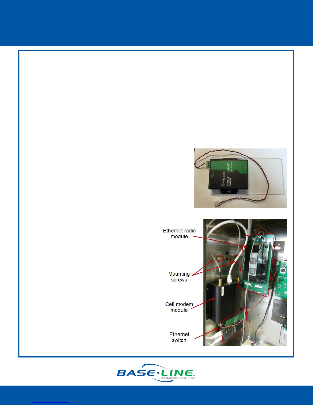
The FlowStation module comes with a 5-port
ruggedized Ethernet switch (BL-ETH-SW).
When the FlowStation is ordered with a BaseStation
3200 irrigation controller in a pedestal, the FlowStation
module is installed in the pedestal at the factory.
The following instructions describe the steps for
installing the add-on module into a pedestal that is
already in service.
Required Tools
You will need a Phillips head screwdriver.
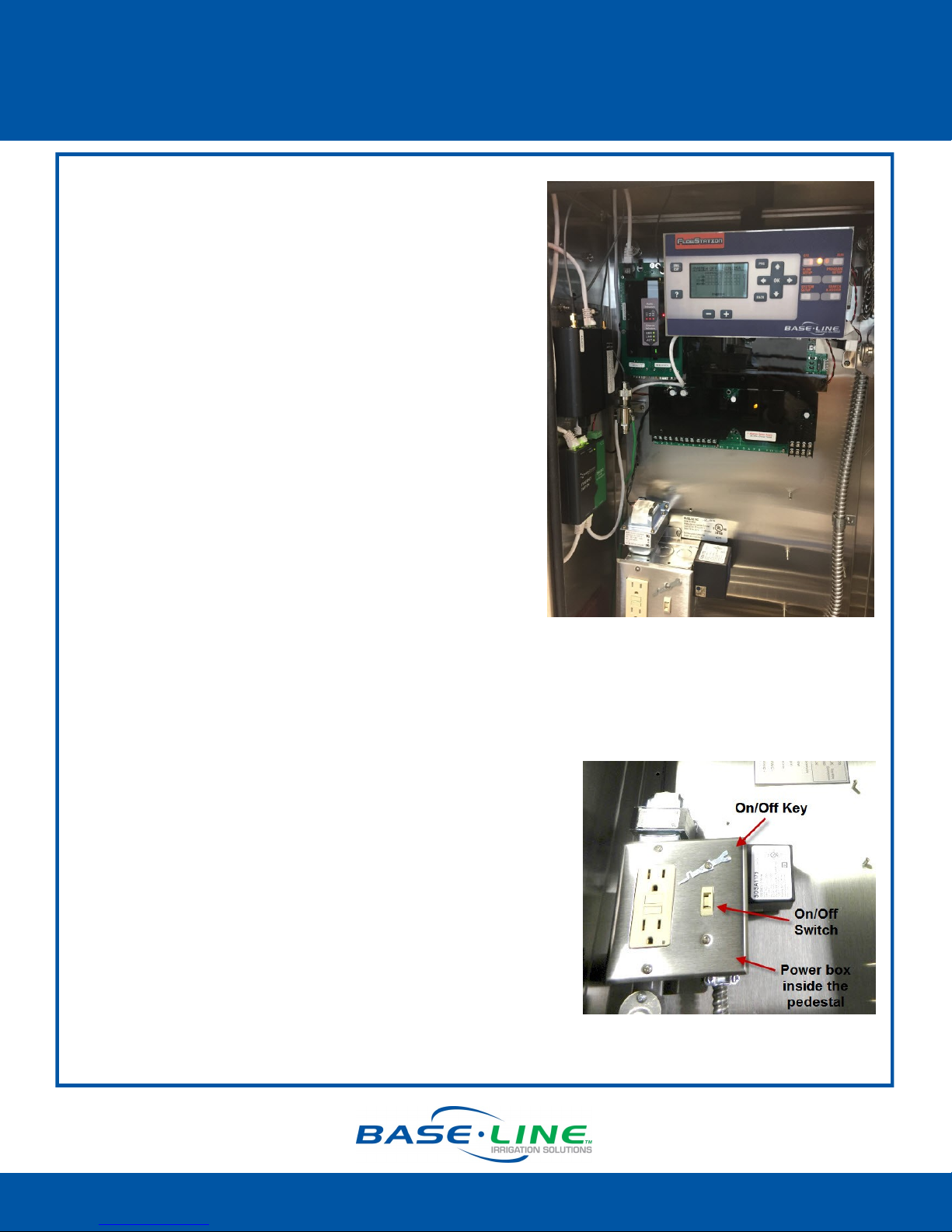
Shutting Down Power to the Pedestal
1. On the BaseStation 3200, turn the dial to the Off
position.
2. Open the lower door on the pedestal and locate the
on/off key on the power box.
3. Remove the screw that fastens the key to the box.
IMPORTANT! Put the screw in a safe place because you
will need to replace it later.
4. Insert the key into the on/off switch and press it down
to turn the power off.
5. Remove the key and reattach it with the screw to
prevent it from being misplaced.
1-866-294-5847 Rev 10.26.2016 www.baselinesystems.com
Page 2
BL-FLOWSTN-P FlowStation Module
Installation Guide
Ethernet Switch Mounting Instructions
1. Before proceeding, verify that the power is off. The LEDs on the BaseStation 3200 faceplate
should not be illuminated.
2. Move the Ethernet radio module out of the way:
Remove the screws used to mount the Ethernet radio module to the back wall. You
may be able to move the Ethernet radio module toward the center of the pedestal
without disconnecting the power and antenna cables. If not, remove the power and
antenna cables, and then set the Ethernet radio module aside in a clean location.
3. On the inside left wall, remove the nuts on the lower edge of the external antenna assembly,
and then remove the screws. Set the nuts aside to be
reused later.
4. Align the holes on the Ethernet switch mounting plate with
the holes on the inside wall of the pedestal.
Note: The photo on the right shows a cell modem
module on the mounting plate with the Ethernet
switch. The cell modem module may not be present in
your configuration.
5. Locate the 2 long screws that were provided
with the Ethernet switch. Working from the
outside of the pedestal, push the screws
through the holes on the pedestal wall and
through the holes on the Ethernet switch
mounting plate.
6. Thread the nuts onto the screws and tighten
them.
7. Replace the Ethernet radio module and
reconnect the power and antenna cables if
necessary.
8. Continue with the Power Connector
instructions on the next page.
1-866-294-5847 Rev 10.26.2016 www.baselinesystems.com
Page 3

BL-FLOWSTN-P FlowStation Module
Installation Guide
Power Connector Instructions
1. Locate the 5-pin splitter that is included with the Ethernet
switch.
2. Inside the pedestal, locate the pair of 5-pin connectors
on the upper end of the control board.
Note: The photo below shows the dust cover removed
from the control board. You may not need to remove the cover to access the 5-pin
connectors.
3. Carefully remove the plug from the lower connector.
4. Attach the 5-pin splitter onto the lower connector.
5. Attach the plug that you removed from the control board onto one of the connectors on
the 5-pin splitter.
6. Attach the end of the power cord from the Ethernet switch to the other connector on the 5pin splitter.
7. Continue with the Attaching the FlowStation Module instructions on the next page.
1-866-294-5847 Rev 10.26.2016 www.baselinesystems.com
Page 4

BL-FLOWSTN-P FlowStation Module
Installation Guide
Attaching the FlowStation Module
1. Make sure the power cable is untangled and
routed around the top of the module.
2. On the middle of the three attachment
points for the FlowStation module (directly
above the capacitor on the control board),
put a washer on one of the stainless steel
screws, and then partially thread the screw
into the standoff.
3. On the mounting plate attached to the
back of the FlowStation module, find the
V-shaped notch. Align that notch with the
screw that you inserted in step 2.
4. Align the other two holes on the mounting
plate with the upper attachment points and
partially thread a stainless steel screw into
each hole.
Tip: To put the screws in these hard-to-reach
locations, you might want to use a magnetic
screwdriver.
5. Verify that the screw with the washer is
securely seated in the V-shaped notch on
the mounting plate, and then tighten the
two screws at the top of the FlowStation
module.
6. Attach the FlowStation power cable to
the connector on the right side of the
BaseStation 3200 control board.
7. Tuck the extra power cable length under
the FlowStation module.
1-866-294-5847 Rev 10.26.2016 ww.baselinesystems.com
Page 5

BL-FLOWSTN-P FlowStation Module
Installation Guide
Attaching the Ethernet Cables
1. Plug one end of each Ethernet cable into a port on the Ethernet switch.
2. Route the 3’ Ethernet patch cable through the top of the pedestal and plug the end into the
Ethernet port on the back of the BaseStation 3200 display board.
3. Plug another Ethernet cable into the Ethernet port on the back of the FlowStation module.
4. Attach an Ethernet cable to the communication module (such as a cell modem gateway or
Ethernet radio) and to one of the ports on the Ethernet switch. Repeat this step for any
additional communication modules.
5. In another Ethernet port, connect an Ethernet cable to the Ethernet wall jack, if needed.
IMPORTANT REMINDER!
Make sure that the shared flow biCoder (BL-3200UPG-SF) has been attached to the two-wire
path of the BaseStation 3200. Refer to the Shared Flow biCoder Installation Guide for instructions.
Turning the Power On
1. Remove the screw that fastens the key to the box.
IMPORTANT! Put the screw in a safe place because you will need to replace it later.
2. Insert the key into the on/off switch and press it up to turn the power on.
3. Remove the key and reattach it with the screw to prevent it from being misplaced.
4. Verify that the Power LED is illuminated on the BaseStation 3200 faceplate.
5. Turn the BaseStation 3200 dial to the Run position.
6. Refer to the FlowStation Quick Start Guide and the FlowStation User Manual for configuration
instructions.
1-866-294-5847 Rev 10.26.2016 ww.baselinesystems.com
 Loading...