

Page 1
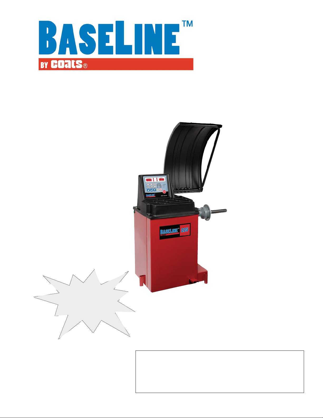
Model 225
Wheel Balancer
See
ÌBalancing Your
First Tire
on page 5.
Safety Instructions
Setup Instructions
Operation Instructions
Maintenance Instructions
READ these instructions before placing unit in
service. KEEP these and other materials delivered
with the unit in a binder near the machine for ease
of reference by supervisors and operators.
Manual Part No.: 85607560 01
Revision: 04/11
Page 2

IMPORTANT SAFETY INSTRUCTIONS
READ ALL INSTRUCTIONS
1. Eye and face protection recommendations:
“Protective eye and face equipment is required
to be used where there is a reasonable probability of injury that can be prevented by the use of
such equipment.” O.S.H.A. 1910.133(a) Protective
goggles, safety glasses, or a face shield must be
provided by the owner and worn by the operator
of the equipment. Care should be taken to see
that all eye and face safety precautions are followed by the operator. ALWAYS WEAR SAFETY
GLASSES. Everyday glasses only have impact
resistant lenses, they are not safety glasses.
2. Do not disable hood safety interlock system, or in
any way shortcut safety controls and operations.
3. Be sure that wheels are mounted properly, the
hub nut engages the arbor for not less than four
(4) turns, and the hub nut is firmly tightened
before spinning the wheel.
4. Read and understand this manual before operating. Abuse and misuse will shorten the functional
life.
5. Be sure the balancer is properly connected to the
power supply and electrically grounded.
6. Do not operate equipment with a damaged cord
or if the equipment has been dropped or damaged – until it has been examined and repaired by
a qualified serviceman.
7. Do not let cord hang over edge of table, bench, or
counter or come in contact with hot manifolds or
moving fan blades.
8. If an extension cord is necessary, a cord with a
current rating equal to or more than that of the
equipment should be used. Cords rated for less
current than the equipment may overheat. Care
should be taken to arrange the cord so that it will
not be tripped over or pulled.
10. Wear proper clothing. Safety toe, non-slip footwear and protective hair covering to contain hair
is recommended. Do not wear jewelry, loose
clothing, neckties, or gloves when operating the
balancer.
11. Keep work area clean and well lighted. Cluttered
and/or dark areas invite accidents.
12. Avoid dangerous environments. Do not use power
tools or electrical equipment in damp or wet locations, or expose them to rain.
13. Avoid unintentional starting. Be sure the balancer
is turned off and power disconnected before servicing.
14. Disconnect the balancer before servicing.
15. Use only manufacturer’s recommended accessories. Improper accessories may result in personal
injury or property damage.
16. Repair or replace any part that is damaged or worn
and that may cause unsafe balancer operation. Do
not operate damaged equipment until it has been
examined by a qualified service technician.
17. Never overload or stand on the weight tray or any
part of the balancer.
18. Do not allow untrained persons to operate machinery.
19. To reduce the risk of fire, do not operate equipment in the vicinity of open containers or flammable liquids (gasoline).
20. Adequate ventilation should be provided when
working on or operating internal combustion
engines.
21. Keep hair, loose clothing, fingers, and all parts of
body away from moving parts.
22. Use equipment only as described in this manual.
9. Keep guards and safety features in place and in
working order.
23. Use only manufacturer’s recommended attachments and accessories.
SAVE THESE INSTRUCTIONS
ii • Important: Always read and follow instructions.
Page 3
Owner’s Responsibility
To maintain machine and user safety, the responsibility
of the owner is to read and follow these instructions:
Definitions of Hazard Levels
Identify the hazard levels used in this manual with the
following definitions and signal words:
• Follow all installation instructions.
• Make sure installation conforms to all applicable
Local, State, and Federal Codes, Rules, and Regulations; such as State and Federal OSHA Regulations
and Electrical Codes.
• Carefully check the unit for correct initial function.
• Read and follow the safety instructions. Keep them
readily available for machine operators.
• Make certain all operators are properly trained,
know how to safely and correctly operate the unit,
and are properly supervised.
• Allow unit operation only with all parts in place and
operating safely.
• Carefully inspect the unit on a regular basis and
perform all maintenance as required.
• Service and maintain the unit only with authorized
or approved replacement parts.
• Keep all instructions permanently with the unit and
all decals/labels/notices on the unit clean and visible.
• Do not override safety features.
Operator Protective Equipment
Personal protective equipment helps make tire servicing safer. However, equipment does not take the
place of safe operating practices. Always wear durable
work clothing during tire service activity. Loose fitting
clothing should be avoided. Tight fitting leather gloves
are recommended to protect operator’s hands when
handling worn tires and wheels. Sturdy leather work
shoes with steel toes and oil resistant soles should be
used by tire service personnel to help prevent injury in
typical shop activities. Eye protection is essential during
tire service activity. Safety glasses with side shields,
goggles, or face shields are acceptable. Back belts provide support during lifting activities and are also helpful
in providing operator protection. Consideration should
also be given to the use of hearing protection if tire
service activity is performed in an enclosed area, or if
noise levels are high.
DANGER
Watch for this symbol:
DANGER
It Means: Immediate hazards, which will result in
severe personal injury or death.
WARNING
Watch for this symbol:
WARNING
It Means: Hazards or unsafe practices, which could
result in severe personal injury or death.
CAUTION
Watch for this symbol:
CAUTION
It Means: Hazards or unsafe practices, which may
result in minor personal injury or product or property
damage.
Watch for this symbol! It means BE ALERT! Your
safety, or the safety of others, is involved!
Important: Always read and follow instructions. • iii
Page 4
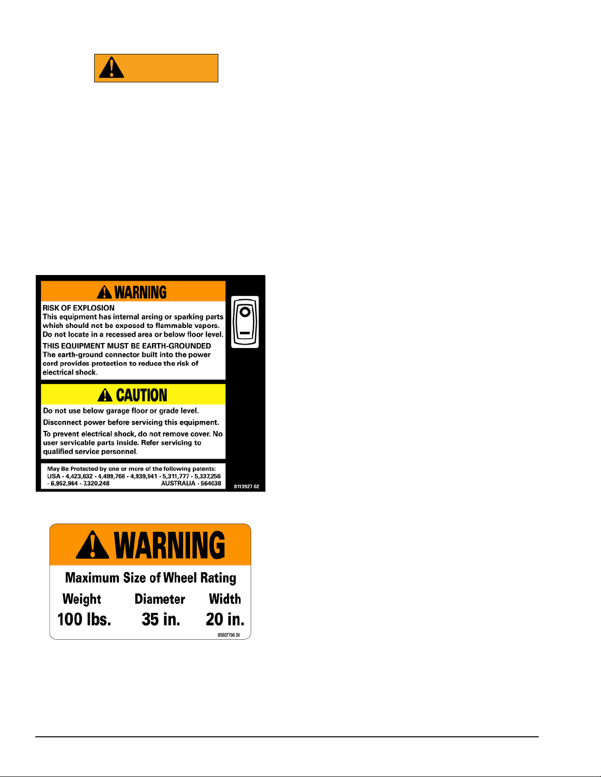
Safety Notices and Decals
WARNING
Failure to follow danger, warning, and caution instructions may lead to serious personal injury or death to operator or bystander
or damage to property. Do not operate this
machine until you read and understand all
the dangers, warnings and cautions in this
manual. For additional copies of either, or
further information, contact:
Hennessy Industries, Inc.
1601 JP Hennessy Drive
LaVergne, TN 37086-3565
(615) 641-7533 or (800) 688-6359
www.ammcoats.com
Standard Safety Devices
• A hood guard of high impact plastic that is designed
to prevent the counterweights from flying out in any
direction except towards the floor.
• A hood switch interlock system that prevents the
machine from starting if the guard is not lowered
and stops the wheel whenever the guard is raised.
iv • Important: Always read and follow instructions.
Page 5

Table of Contents
Important Safety Instructions ................................. ii
Owner’s Responsibility ............................................iii
Operator Protective Equipment ...............................iii
Definitions of H azard Levels ....................................iii
Safety Notices and Decals ......................................iv
Standard Safety Devices .........................................iv
Setup Instructions ............................................... 2 - 3
Receiving ................................................................. 2
Unpacking the Unit .................................................. 2
Remove Balancer from Pallet .................................. 2
Floor and Space Requirements ............................... 2
Electrical Requirements .......................................... 2
Wheel Guard Installation ......................................... 3
Connect to Power .................................................... 3
Initial Testing ............................................................ 3
Specifications ............................................................ 4
Accessory Options .................................................... 4
Features ..................................................................... 4
Balancing Your First Tire ........................................... 5
Principle Operating Parts .................................... 6 - 7
Know Your Unit ........................................................ 6
Power Switch........................................................... 6
Using The Offset Arm .............................................. 7
Control Panel ........................................................... 7
Rounding ................................................................. 7
Ounce/Gram ............................................................ 7
Wheel Guard ........................................................... 7
Brake Pedal .............................................................. 7
Auto Stop Feature ................................................... 7
Mounting Wheel on Spindle Shaft ..................... 8 - 9
Standard Back Cone Mounting ................................ 8
Standard Front Cone Mounting ............................... 9
Setting Wheel Dimensions (DIM) ....................10 - 11
Definition of DIM ....................................................10
Wheel Data Entry (W, D, A) ....................................11
Balancing Programs ........................................ 12 - 13
Dynamic Balancing ................................................ 12
Static Balancing ..................................................... 12
Aluminium Wheel .................................................. 13
Attaching Corrective Weights ................................ 14
Match Balance (Optimization) ........................ 14 - 15
Match Balance Program ........................................ 14
Quick OPT Program ............................................... 15
Calibration Program ............................................... 16
First Sensitivity Calibration .................................... 16
Second Sensitivity Calibration ............................... 16
Diagnostic Procedures ........................................... 17
After Balance Vibration Problems ...........................17
Balancing Accessory Availability Status ..................17
Troubleshooting ...................................................... 18
Error Display .......................................................... 19
Maintenance Instructions ...................................... 20
Glossary Of Terms ................................................... 21
NOTICE
Read entire manual before assembling,
installing, operating, or servicing this
equipment.
Important: Always read and follow instructions. • 1
Page 6
Setup Instructions
Receiving
The shipment should be thoroughly inspected as soon
as it is received. The signed bill of lading is acknowledgement, for the carrier, of receipt in good condition
of the shipment covered by our invoice.
If any of the goods called for on this bill of lading are
shorted or damaged, do not accept them until the carrier makes a notation of the shorted or damaged goods
on the freight bill. Do this for your own protection.
NOTIFY THE CARRIER AT ONCE if any hidden loss or
damage is discovered after receipt and request him to
make an inspection. If the carrier will not do so, prepare
an affidavit to the effect that you have so notified the
carrier (on a certain date) and that he has failed to comply with your request.
IT IS DIFFICULT TO COLLECT FOR LOSS OR DAMAGE AFTER YOU HAVE GIVEN THE CARRIER A CLEAR
RECEIPT.
File your claim with the carrier promptly. Support
your claim with copies of the bill of lading, freight bill,
invoice, and photographs, if possible.
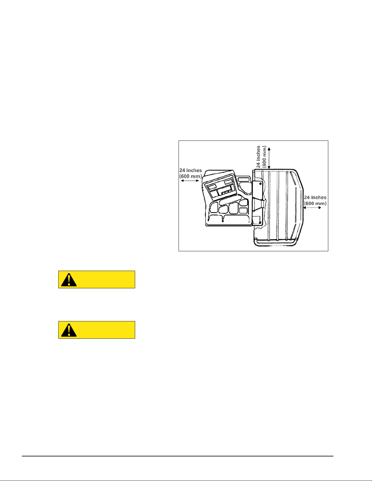
Floor and Space Requirements
The balancer must be located on a flat floor of solid
construction, preferably concrete. The balancer must
sit solidly on its three feet. If the balancer is not level,
does not sit solidly on its three feet, or is placed on an
unstable floor, the balancer will not function properly
and may produce inaccurate balance readings.
Do not operate the balancer while it is on the pallet.
Select a location for the balancer that provides a level,
solid floor, and adequate clearance around and above
the balancer. Make sure the location selected has
enough room above and behind the unit so the hood
can be raised completely. The location must also provide working room for mounting and removing wheels.
Make sure the area has adequate lighting.
Unpacking the Unit
• Remove the shipping carton from the pallet.
• Remove all loose parts and accessories packed
around the unit.
Remove Balancer from Pallet
1. Remove the shipping bolts that hold the balancer
to the pallet.
CAUTION
Do not use the control panel, control panel
base, accessory storage, faceplate, hood or
shaft to lift the balancer.
CAUTION
Use help to remove the balancer from the
pallet. The unit is heavy and the weight is
not evenly distributed. Dropping the unit
may cause personal injury or equipment
damage.
Figure 1 - Space Requirements
Electrical Requirements
See serial tag for the appropriate power requirements
of your machine.
Always have a qualified electrician install the proper
receptacles in accordance with state and local codes.
2. Lift the balancer off the pallet and place it in its
operating location.
2 • Important: Always read and follow instructions.
Page 7
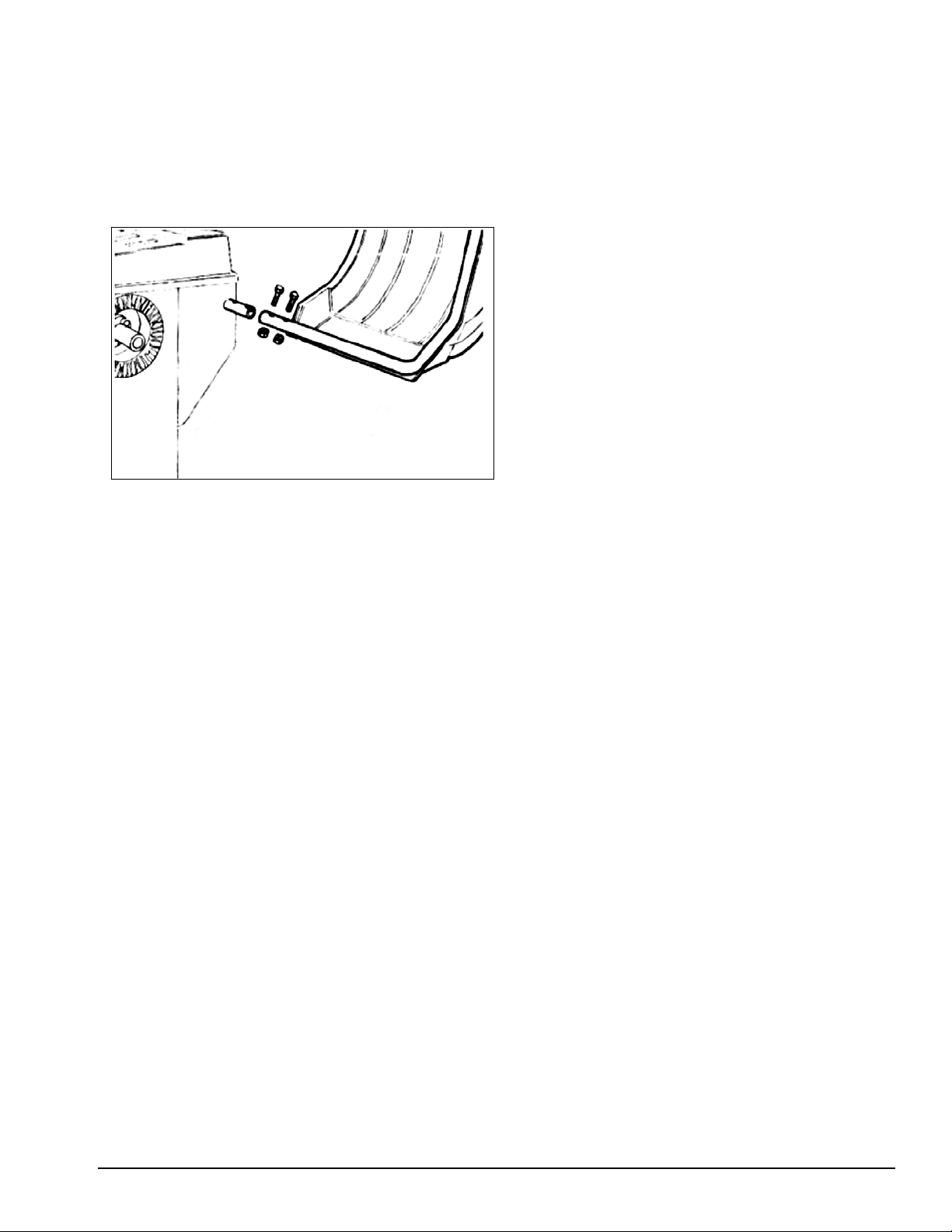
Wheel Guard Installation
1. Unscrew the nuts that lock the two bolts on the
wheel guard support pin holes and take out the bolts.
2. Fit the wheel guard tube into the support pin, lining
up the two sets of holes.
3. Fit the two bolts into the holes and attach the
wheel guard on to the support by tightening up the
nuts.
Figure 2 - Install Wheel Guard Onto Balancer
Connect to Power
Your factory trained COATS® Service Technician should
do the final check to verify the power installation before
connecting the balancer to a power supply. Failure due
to improper power connection may void the warranty.
Initial Testing
1. Plug the unit into an appropriate power outlet. If
the circuit breaker for the outlet is off, turn it on.
2. Turn the balancer on. The power switch is on the
back of the unit.
Important: Always read and follow instructions. • 3
Page 8

Specifi cations
Standard Accessories
Wheel Diameter Range
8 - 23 inches (203 - 584 mm)
Wheel Width Range
1.5 - 20 inches (40 - 510 mm)
Maximum Outside Tire Diameter
Up to 35 inches (900 mm)
Maximum Tire/Wheel Weight
100 pounds (45.4 Kg)
Mounting Shaft Diameter
40 mm
Resolution (Round Off Mode)
0.25 ounce, position 1.40 degrees
Resolution (Non-Round Off Mode)
0.10 ounce, position 1.40 degrees
Balancing Display Increments
0.25 or 0.10 ounces
Electrical Requirements
115 V, 1 Ph, 5 amp
230V, 1Ph, 2.5 amp
(use grounding type plug)
Footprint
43 x 39 inches (1090 x 980 mm)
• 8112107 Cone Spring
• 8112098 Small Cone
• 8112099 Medium Cone
• 8112100 Large Cone
• 8112106 Small Pressure Drum with Ring
• 8113175 Wheel Weight Hammer
• 8112103 Hub Nut
• 8309011 Caliper
Features
• Integrated LED touch panel display
• 8 balancing modes, including dynamic clip, static,
match, and 5 tape-a-weight™ options
• Positioning foot pedal system to hold assembly in
place while placing weights
• Space-saving design
• Access to COATS® extensive Factory Authorized
service network
• 6 months Parts Warranty
Shipping Weight
251 pounds (114 Kg)
(without accessories)
4 • Important: Always read and follow instructions.
Page 9
ÌBalancing Your First Tire
1. Turn the machine OFF then ON
(resets machine).
Note: The machine wakes up using standard
clip-on wheel weight locations (C1 & C2) and
wheel dimensions.
2. Mount a tire/wheel on the bal-
ancer that will use standard
clip-on wheel weights.
Use the most appropriate mounting method.
3. Always remove any weights
already attached to the wheel.
4. Enter A & D wheel dimensions
using offset arm.
7. Raise hood after tire stops rotating.
Note: Wait for wheel to stop before raising the
hood.
8. Rotate wheel to inboard (left
plane) position of unbalance.
9. Attach inboard (left plane) corrective weight.
Attach specified weight amount at top-dead-
center on inside flange of wheel.
10. Rotate wheel to outboard (right
plane) position of unbalance.
11. Attach outboard (right plane)
corrective weight.
Attach specified weight amount at top-dead-
center on outside flange of wheel.
12. Lower the hood to respin the
tire/wheel and check balance.
Figure 3 - Offset Arm At Clip-On Weight Location
5. Enter Width wheel dimension.
Use plastic calipers to measure wheel width
from wheel flange to wheel flange. Use keypad
to enter Width value.
6. Lower the hood, press Start;
wheel spins and unbalances are
measured and displayed.
After the beep signal, the corrective weight
amount appears in the digital readout windows.
Your weight readings should now be 0.00.
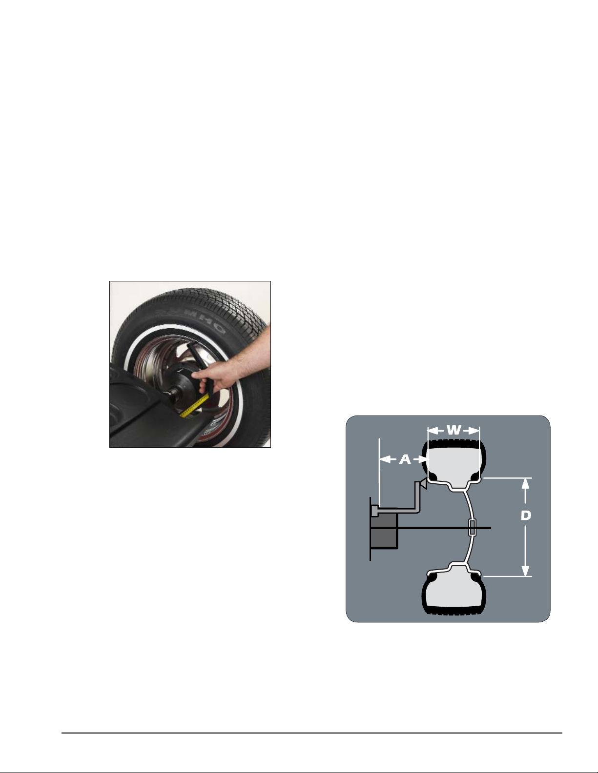
Note: Throughout this manual tire dimensions
are referred to as A, W, and D, see figure 4.
Figure 4 - A, W, and D Tire Dimensions
Important: Always read and follow instructions. • 5
Page 10

Principle Operating Parts
❶
❺
❶
❺
Know Your Unit
Compare this illustration with the unit before placing
it into service. Maximum performance and safety will
be obtained only when all persons using the unit are
fully trained in its parts and operation. Each user should
learn the function and location, of all controls.
Prevent accidents and injuries by ensuring the unit is
properly installed, operated and maintained.
❺
❸
❷
❶
❹
❼
❻
Note: Throughout this manual wheel weights are
referred to as Clip-on or Tape-A-Weight®. Figure 5
shows an example of each weight.
Clip-on Weight Tape-A-Weight
Figure 5 - Corrective Weight Examples. For Best Results, use
BADA® Brand Wheel Weights.
®
Power Switch
The ON/OFF switch location is on the side of the
balancer; below the weight tray. After the beep and the
lamp test, the machine is ready to receive the wheel
data.
❽
❶ Control Panel
❷ Plug (back of machine)
❸ ON/OFF Switch
❹ Weight Tray with Pockets for Tape-A-Weight
Boxes; Individual Weights
❺ Wheel Guard
❻ Offset Arm, Measures A & D of Tire/Wheel
(shown in home position)
❼ 40 mm Shaft
❽ Positioning Pedal
ON/OFF
Power
Switch
Figure 6 - On/Off Switch
6 • Important: Always read and follow instructions.
Page 11

Using The Offset Arm
A
B
C
D
EE
F
G
When not in use store the offset arm in the home
position as shown in figure 7.
Offset Arm
In Home
Position
Figure 7 - Offset Arm Stored In Home Position
Rounding
When the machine is switched on, its default setting
is to show the unbalance to the nearest five grams
(rounding up or down as necessary) or to the nearest
1/4 ounce if data output in ounces has been set. In this
default setting, the first 4 grams are not displayed since
they are regarded as below the operational threshold
(the “Thr”LED will turn off) and the unbalance will be
shown to the last gram (or to the last 1/10 of an ounce
if this display made is active).
Each time the
between threshold ON and threshold OFF.
is press, the machine toggles
Ounce/Gram
Control Panel
A Inboard Plane Display (left)
B Outboard Plane Display (right)
C Inboard Plane Position Indicator
D Outboard Plane Position Indicator
Keys and LEDs for Selecting and Displaying
Available Programs
F Key and LED for Selecting Round Off Mode
and Units
G Key for Input of Wheel Data
Note: By pressing the and holding it down for
about five seconds, you can set up the machine to display out of balance values in grams or ounces.
Wheel Guard
CAUTION
Never raise up the wheel guard before the
wheel has come to a stop. Keep hair, loose
clothing, fingers and all parts of body away
from moving parts.
If, due to a fault in the machine, the wheel keeps spinning permanently, switch off the machine at the master
switch or by unplugging the plug from the power supply.
Wait until the wheel stops, or actuate the positioning
pedal before opening the wheel guard.
Positioning Pedal
CAUTION
Do not actuate the positioning pedal during
the measurement cycle. Do not use the positioning pedal as a brake.
After the machine has completed its spin cycle, use
the positioning pedal to hold the wheel position during
weight application. When you press the pedal with your
foot, the spindle shaft is locked.
If you have to brake the wheel in an emergency situation, while it is being spun by the motor, first disconnect
the power to disengage the motor and then use the
positioning pedal.
Auto Stop Feature
When the wheel is spun and out of balance measurements are displayed, the balancer’s auto stop feature
stops the wheel automatically at the corrective weight
location (12 o’clock).
Important: Always read and follow instructions. • 7
Page 12

Mounting Wheel On Spindle Shaft
Select the most appropriate mounting method for
the wheel you are balancing. Using the proper method
ensures secure mounting and safe balancer operation,
and prevents damage to the wheel.
On most wheels, the inner side of the wheel hub usually has the most uniform surface for wheel balancing.
Always center the wheel by the most uniform shaped
side of the hub to achieve the most accurate balance.
Regardless of mounting type, always make sure that
the wheel is forced firmly against the shaft faceplate
and that the hub nut engages the threaded shaft for
at least four complete turns. To assist in centering the
wheel properly, rotate the wheel and the shaft while
tightening the hub nut.
CAUTION
Standard Back Cone Mounting
Most original equipment and steel wheels can be
mounted properly using this method. The wheel is centered on a cone from the inner side of the hub.
Failure to tighten the hub nut properly may
result in the wheel dismounting, causing
personal injury and property damage.
Figure 8 - Back Cone Mounting
1. Select the cone that best fits the center hole in the
wheel. Slide the cone onto the shaft with the large end
towards the faceplate.
2. Lift wheel onto the shaft and center it on the cone.
3. Attach the pressure cup to the hub nut and install
the assembly onto the shaft. Tighten securely.
Note: Use a nylon spacer (no mar ring) to protect custom wheel finishes.
4. Thread the hub nut onto the shaft, and tighten it
against the wheel. The wheel must be forced firmly
against the faceplate. The hub nut must engage the
threads for at least three full turns.
Note: If the hub nut will not tighten completely, use
the front cone mounting method.
8 • Important: Always read and follow instructions.
Page 13

Standard Front Cone Mounting
A wheel should be centered by the outer side of the
hub only when the inner surface will not provide an
accurate surface to center on.
Figure 9 - Front Cone Mounting
1. Select the cone that best fits the center hole in
the wheel.
2. Lift the wheel onto the shaft and slide it back
against the shaft faceplate.
3. Slide the cone onto the shaft and into the center of
the wheel. You will need to lift the tire to seat the cone
in the center hole.
4. Install the hub nut (without pressure cup) onto the
shaft. Tighten it securely against the cone. The hub nut
must engage the threads for at least three full turns.
Note: If the hub nut will not tighten completely
because of a lack of threads, use an additional cone as
a spacer between the mounting cone and the hub nut.
The wheel must be forced firmly against the faceplate.
Important: Always read and follow instructions. • 9
Page 14

Setting Wheel Dimensions (DIM)
Before a wheel can be balanced, wheel dimensions
must be entered into the computer.
Definition of DIM
W = Width
The width of the wheel at the
rim flanges, measured with the
calipers as shown in figure 12.
D = Diameter
The diameter of the wheel as
indicated on the tire.
A = Offset
The distance measured from
the balancer (“0” on offset
arm) to inner plane of the rim
(inner weight location).
A2 = Offset
The distance measured from the balancer (“0” on
offset arm) to outer plane of the rim (outer weight location). Typically used in ALU programs.
D2 = Diameter
The diameter as measured at the A2 weight location.
Typically used in ALU programs.
Figure 11 - A2 and D2 Tire Dimensions
Figure 10 - W, D, and A Tire Dimensions
Note: Only use calipers provided by the wheel bal-
ancer manufacturer because others may not be the
same.
Note: A thick flange, on some aluminum wheels, can
effect the measured diameter. For example, a 16-inch
rim can have a measured diameter of 15.5-inches.
10 • Important: Always read and follow instructions.
Page 15

Wheel Data Entry (W, D, A)
9. Read the machine/rim distance on the gauge.
1. Press . The machine is ready to receive the
WIDTH (W) measurement (the corresponding LED will
light).
2. Measure rim width using the caliper provided with
the balancer (figure 12).
Figure 12 - Caliper Placement On Wheel
3. Press or until the correct WIDTH
number is set in the right display window.
10. Press or until the correct OFFSET
number is set in the right display window.
11. Lower hood and press to spin wheel.
Note: If you hold down or the numbers
will spool up or down quickly making data input all the
more rapid.
Note: DIM inputs can be converted between inches
and millimeters.
To do this press to toggle between an inch or
millimeter measurement display. A LED on the panel
will light to identify the current unit of measurement
(mm or inch).
Note: When in static mode, you only need to input the
DIAMETER wheel measurement.
4. Press to confirm the W input and set up the
machine to receive the DIAMETER (D) measurement
(the corresponding LED will light).
5. Read the diameter that is printed on the tire.
6. Press or until the correct DIAMETER
number is set in the right display window.
7. Press
machine to receive the OFFSET (A) measurement (the
corresponding LED will light).
8. Move the offset arm until it touches the edge of
the inside rim flange as shown figure 13 according to
the different terminal available on the gauge.
to confirm the D input and set up the
Figure 13 - Offset Arm at Clip-on Weight Location
Important: Always read and follow instructions. • 11
Page 16

Balancing Programs
A variety of wheel configurations can be balanced
using this wheel balancer. Read through this section, it
will help you determine which program and options are
best suited for certain wheel assemblies.
To perform a balancing cycle:
• Mount the wheel on the shaft using the most appropriate method. Refer to Mounting Wheel on Shaft,
pages 8 & 9.
• Remove any balancing weights, stones, dirt or other
foreign bodies from the wheel.
• If necessary, select a balancing program.
• Input wheel data correctly. Refer to Setting Wheel
Dimensions (DIM), pages 10 & 11.
Dynamic Balancing
Choose a dynamic balance to balance a wheel using
two planes for correction. Select the weight option that
best fits the available weight locations.
Clip-on Weights - The standard default; used for most
passenger tire/wheel assemblies using the most common location for corrective weights. Clip-on weights are
placed on the inner and outer rim flanges.
• Press
ing program LED lights up. The two clip-on weight
LED locations light up on the rim diagram.
• Press to confirm your choice.
or until the DYN balanc-
• Lower hood and press
• Wait for the beep that signals the wheel measurement cycle is complete.
• Use the positioning pedal to stop the wheel spin-
ning; then raise the wheel guard.
• Observe the corrective weight amount requirements
displayed for the inside and outside planes respectively.
• Choose the first side you intend to balance and
rotate the wheel until the center indicator light
flashes and you hear a confirming beep.
• Attach the corrective weight at top-dead-center (12
o’clock) on the tire/wheel assembly. Refer to Attaching Corrective Weights, page 14.
• If necessary, repeat the process for the other side
of the wheel.
to spin wheel.
C1 & C2
Note: The standard dynamic balancing program using
clip-on weight locations is the default setting, when the
machine is switched on.
Static Balancing
Choose a static balance to balance a wheel using one
plane for correction. Place the single corrective weight
at top-dead-center (12 o’clock) on either flange, at the
center of the rim channel or place half of the displayed
weight on both planes.
• Press or until the STATIC bal-
ancing program LED lights up.
• Press to confirm your choice.
STATIC
• Lower hood and press
check balance. Your weight readings should now be
0.00.
Important: Be aware that a slight error (a degree or
two) in positioning the corrective weight on the tire/
wheel assembly can produce a residual out of balance.
to spin wheel and
Note: When in static mode, you only need to input the
DIAMETER wheel measurement.
Important: If you decide to use the rim channel for
corrective weight placement, remember you may need
to adjust the DIAMETER measurement input. Typically
you would make it 2 or 3 inches less than the actual tire/
wheel diameter.
12 • Important: Always read and follow instructions.
Page 17

Aluminium Wheel
Choose from 5 ALU programs that represent typical
corrective weight positions for aluminum wheels using
a dynamic balance. The balancer’s ALU programs calculate out of balance values based on the wheel dimension measurements (DIM) entered for the tire/wheel
assembly.
ALU (Aluminum Wheels) - To balance aluminium
wheels you usually use a self-adhesive weight location
that is positioned differently from the clip-on weight
position(s) used in standard balancing.
• Press
ing program lights up.
• Press the number of times needed to select
your ALU program choice (the rim diagram on the
panel illustrates the type of weights and balancing
planes for each ALU program).
or until the ALU balanc-
ALU 1
ALU 1P
ALU 2
ALU 2P
ALU 3
ALU 4
ALU 5
Note: If the WIDTH you input is less than 4-inches or
the DIAMETER is less than 11-inches, an Alu Err message may appear. This means that the width and diameter input cannot be used for the ALU program selected.
Important: Always read and follow instructions. • 13
Page 18

Attaching Corrective Weights
• Rotate the wheel until the center indicator light
flashes and you hear a confirming beep.
• Attach the corrective clip-on weight amount at top-
dead-center (12 o’clock) on the tire/wheel assembly.
If the program ALU 1P is running, place the corrective Tape-A-Weight™ amount at the exact position
and plane chosen when entering the wheel measurement data.
• Lower hood and press to spin wheel and
check balance. Your weight readings should now be
0.00.
Match Balance (Optimization)
WARNING
The Match Balance involves the loosening of
tire beads and the inflation of a tire. Training
is necessary in tire changer operation and
understanding the dangers involved during bead seating and tire inflation before
attempting this stage of the Match Balance
procedure. Read the operators manual supplied with the tire changer and consult a
supervisor.
Use the Match Balance (Tire/Rim Weight Optimization) program to determine the best mating of tire and
rim that will result in the least amount of total out of
balance of the assembly. It requires two spins and two
rotations of the tire on the rim. Match Balance may be
needed when:
• The customer complains of ride problems.
• The balancer calculates a high out of balance.
Important: A high out of balance may indicate the
improper mounting of the assembly on the balancer, or
a rim that is out of round or misformed, or a tire with a
bubble or other problem. If the out of balance is excessive, it may be prudent to replace the rim, the tire, or
both. If either is replaced, do not continue with Match
Balance. Balance the new tire and rim and evaluate the
readings.
Match Balance Program
Choose the match balance program only after the
wheel has spun and the corrective weight amount is
displayed.
• Press or until the MATCH
balancing program LED lights up.
• Press to confirm your choice.
When you select this program, the balancer calculates
whether it is worthwhile. The balancer will flash the
message:
• Yes OPT if it is worth the effort.
• No OPT if it is not.
This calculation is made based on the out of balance
found with the last spin made (therefore, the last spin
must refer to the wheel on the machine).
You are now ready to move into the first stage of the
program as signaled on the display. If you do not want
to continue with this program, press
.
14 • Important: Always read and follow instructions.
Page 19

OPT 1
• Mount the rim without the tire on the balancer.
• Turn it until the valve (or hole) is at 12 o’clock.
• Press
• Make the first spin (as instructed by the display). At
the end of the spin, the program goes into its second stage.
OPT 2
• Remove the rim from the balancer.
• Put the tire on the rim. Put the tire on the balancer.
• Turn it until the valve is at 12 o’clock.
• Press .
• Make the second spin. At the end of the spin, the
program goes into the third stage of the OPT program.
OPT 3
• Turn the wheel until the segment in the middle of the
screen lights up to indicate the position.
• Make a chalk mark on the outside wall of the tire at
12 o’clock.
.
• Press
• Make the forth spin. At the end of the spin, the OPT
program is complete, and the machine displays the
corrective weight amounts to balance the wheel.
If you make an error, which will negatively affect the
end result, the machine will tell you this by, displaying a
message: OPT Err. This means you need to repeat the
entire procedure from the beginning.
Note: If you do not want to make the first spin with
just the empty rim, you can skip the first phase by
pressing
for the OPT program. This will mean that you start by
mounting the rim plus tire on the balancer and carrying
out phases 2, 3, 4 as previously described.
Note: At the end of the second and third spin you may
get the message OUT 1 or OUT 2 on the screen. This
means that you are better off abandoning the program
by pressing the . The display will then give the
weights needed to balance the wheel. This allows you
to short cut (exit) the program by accepting the current
status. If you want to carry on to the end, press the
.
immediately after pressing the
• Remove the wheel from the balancer.
• Turn the tire on the rim until the chalk mark is opposite the valve (i.e. 180°).
• Remount the wheel on the balancer until the valve
is at 12 o’clock.
• Press .
• Make the third spin. At the end of the spin, the pro-
gram goes into its fourth and last stage.
OPT 4
• Turn the wheel until the segment in the centre lights
to indicate the correct position.
• Make two chalk marks on the outside wall of the tire
at 12 o’clock. If the screen gave you the message to
switch around the tire as it is mounted on the rim,
make these two chalk marks on the inside wall of
the tire.
• Turn the tire on the rim (and switch it around if this is
called for) so that the two chalk marks are opposite
to the valve.
and you will continue in the OPT program.
Note: At the end of the third spin the screen may sug-
gest that you switch the tire around on the rim. If you do
not want to or cannot do this, press . The screen
will display instructions on how to complete the OPT
program without making this switch.
Quick OPT Program
In the vast majority of cases this program gives results
almost as good as the full OPT program described
above, although it requires fewer spins.
Proceed as outlined above in the previous heading
with the difference that the first stage of the quick optimization program corresponds to the second stage of
the standard program.
You therefore start work with the tire already on the
rim and then proceed with the successive stages.
• Mount the wheel on the balancer.
• Turn the wheel until the valve is at 12 o’clock.
Important: Always read and follow instructions. • 15
Page 20

Calibration Program
First Sensitivity Calibration
This program needs to be run whenever the settings
appear to be out of tolerance or when the machine
requests self-calibration spontaneously by displaying
the message “Er1 CAL”.
• Select a wheel of average size and weight, preferably
with a limited unbalance, and mount it on the shaft.
• Enter the correct wheel dimensions for the wheel.
• Press
gram LED lights up.
or until the CAL pro-
Remember: Remove the 100 g (3.5 oz) sample weight
at the end of the procedure.
Note: The
to abort the calibration procedure and return to the program selected previously.
Note: The calibration described above is valid for any
type of wheel.
can be pressed at any given moment
Second Sensitivity Calibration
This program is used to self-calibrate the machine to
make it extremely accurate even with very high out of
balance values (over 200 g of static unbalance with average size wheels). It should be done when the machine
itself calls for it by displaying the message “Er2 CAL”.
• Press to confirm your choice.
• The machine is now ready to carry out first sensitivity
calibration and displays the message “CA.1”.
• Rotate the wheel until the center indicator light
flashes and when the value ”100” (or 3.5 if ounce
mode is selected) is on the display.
• Attach a 100 g (or 3.5 oz) sample weight to the OUT-
SIDE of the wheel rim. Position it at top-dead-center
(12 o’clock) exactly.
• Lower hood and press to spin wheel.
• With the wheel stopped, remove the sample weight
from the outside plane and rotate the wheel until
the center indicator light flashes and when the value
“100”(or 3.5) is on the display.
• Attach the 100 g (or 3.5 oz) sample weight once
again to the OUTSIDE of the wheel rim. Position it at
top-dead-center at 12 o’clock exactly.
• Select a wheel of average size and weight, preferably
with a limited unbalance, and mount it on the shaft.
• Enter the correct wheel dimensions for the wheel.
• Press or until the CAL pro-
gram LED lights up.
• Press twice to confirm your choice. The
machine is now ready to carry out second sensitivity calibration and will signal this with the message
“CA.2”.
• Follow all the steps outlined above for first sensitivity
calibration.
• Lower hood and press
When the calibration program is completed successfully, it is confirmed by a beep following the spin. If not,
the message “Er3 CAL” is displayed.
The self-calibration program ends with the display
showing out of balance values for the wheel (ignoring
the sample weight).
to spin wheel.
16 • Important: Always read and follow instructions.
Page 21

Diagnostic Procedures
After Balance Vibration Problems
If vibration is still present after balancing the wheels
and driving the vehicle on smooth pavement, remove
the wheels and recheck the balance. If a wheel is out
of balance the cause may be:
• Wheel was not mounted/centered correctly on the
balancer.
• A weight has come off the wheel (possibly the
wrong clip style). Remove the other weights from
the wheel and rebalance.
• Foreign material inside the tire. Remove the tire
from the wheel, remove the foreign material, and
remount. Remove wheel weights and rebalance the
wheel.
• Stones or other foreign objects caught in the tire
tread or rim. Remove the objects. Check and rebalance if needed.
If the balancer still indicates the wheels are balanced
to within 0.10 ounces on both inner and outer displays,
the problem is not in the balance of the wheels. Check
the following possible sources of vibration:
Balancing Accessory Availability Status
This check permits you to make sure that wear has not
altered the mechanical specifications of flanges, cones
and so on beyond the specified limits.
The test is carried out with a perfectly balanced wheel
(to zero without the threshold and showing the first
gram). When this wheel is mounted on the balancer,
removed and remounted in a different position the
unbalance weight shown should not be more than 10
grams.
If the unbalance is higher, check all the accessories
with care and replace any that show dents, abnormal
wear, bent flanges and so on.
Always remember that if you are using a cone to
center the wheel on the shaft, you will never get good
results if the centre hole in the rim is not perfect, i.e. off
center or out-of-round. Results are always better when
the wheel is centered with the rim holes.
A last important point: any difference between the
way the wheel is mounted on the car and on the balancing machine will generate some unbalance.
• Tire pressure. Bring all tires up to the recommended
PSI.
• Radial or lateral runout in the tire or wheel. Replace
the damaged part.
• Unbalance in wheel covers or trim rings. Remove
the wheel covers or trim rings and test drive. If
the vibration is gone, remove the shaft and use
an appropriate adapter to mount the wheel to the
balancer. Balance the wheel with the wheel cover
or trim ring attached to the wheel.
• Incorrectly mounted tire and wheel. Remount correctly.
• Damaged wheel bolt holes. Replace wheel.
• Worn universal joints. Replace as required.
• Drive shaft unbalance or damaged. Balance, repair,
or replace.
• Unbalance in brake rotor(s) or drum(s).
• Suspension out of alignment. Align the vehicle and
replace any damaged or worn parts.
Important: Always read and follow instructions. • 17
Page 22

Troubleshooting
Listed below are faults that the user can remedy if
the cause is found to be among those indicated. Any
other defect or malfunction will require the attention of
a qualified technician: Contact your nearest BaseLine™
service center.
ERROR
Machine fails to switch on,
with no light showing at the
main switch.
Machine fails to switch on,
even with the light showing at
the main switch.
Wheel fails to spin when
START button is pressed.
Machine gives discontinuous
unbalance values.
Several spins are needed to
balance a wheel.
CAUSE
No power at the socket.
Defective main plug.
One of the fuses F1, F2, F3 at
the circuit board has blown.
The wheel guard is raised.
The machine has been jolted or
destabilized during the spin.
The machine is not sitting level
on the floor or is on an unstable
floor.
The wheel is not properly
clamped.
The machine has been jolted or
destabilized during the spin.
The machine is not sitting level
on the floor or is on an unstable
floor.
The wheel is not properly
clamped.
The wheel dimensions entered
are incorrect.
The machine is not properly
calibrated.
REMEDY
➤ Test the main voltage.
➤ Check the electrical power circuit
installed in the workshop.
➤ Check the integrity and efficiency of
the plug, and replace if necessary.
➤ Replace the blown fuse.
➤ Lower the guard.
➤ Repeat the spin, taking care not to
disturb the machine while data acquisition is in progress.
➤ Verify the stands and adjust the feet,
utilizing shims if necessary.
➤ Tighten the hubnut so that the wheel
is firmly restrained.
➤ Repeat the spin, taking care not to
disturb the machine while data acquisition is in progress.
➤ Verify the stance and adjust the feet,
utilizing shims if necessary.
➤ Tighten the hubnut so that the wheel
is firmly restrained.
➤ Verify the dimensions and program
correctly.
➤ Run the calibration procedure.
18 • Important: Always read and follow instructions.
Page 23

Error Display
The machine recognizes a number of incorrect opera-
tions and displays this as an error message.
ERROR CODE DESCRIPTION
Er1 CAL Error in first sensitivity calibration. Do the first sensitivity calibration procedure.
Er2 CAL Error in first sensitivity calibration. Do the first sensitivity calibration procedure.
Er3 CAL Calibration was done without using the 100 g standard weight. Repeat calibration with the
correct calibration weight.
Er4 CAL First sensitivity calibration was done with a tire with a too high out of balance. Balance the
wheel (or at least reduce its out of balance) and repeat calibration.
Er5 CAL Gauge calibration error. Carry out gauge calibration.
Err 7 The machine cannot give the data asked for. Do a spin and repeat the request.
Err 10 Internal distance gauge not in rest position (completely in) when the machine is turned
on. Turn off the machine, return the gauge to its correct position and turn on again. Potentiometer malfunction. Press the key to disable the gauges and enter the data from the
keyboard.
Err 11 Diameter potentiometer malfunction. Press the key to disable the gauges and enter the
data from the keyboard. Contact technical assistance for help.
Err 20 Gauges not in correct position during calibration. Move them to the correct position and
repeat calibration.
Alu Err Incorrect wheel data input for an aluminium wheel balancing program (ALU). Correct the
data.
OPT Err Error made during the OPT procedure (optimization). Repeat from the beginning.
Cr Err Spin made with wheel guard up.
Other Messages
CA.1 (GO) First sensitivity calibrating spin.
CA.2 (GO) Second sensitivity calibrating spin.
GO Alu Spin with Alu program.
GO d15 Spin with motorcycle dynamic program.
GO A15 Spin with motorcycle Alu program.
GO CTS Spin with CTS program.
St Spin with static balancing program.
CCC CCC Out of balance higher than 9 oz. / 255 grams.
Important: Always read and follow instructions. • 19
Page 24

Maintenance Instructions
The balancer requires only minor maintenance to keep
the unit operating properly.
1. Keep the display clean and clear. Use a damp cloth.
Do not use cleaners or solvents which leave oily or filmy
residues behind.
2. Keep the adapters, cones, faceplate, threaded
shaft, pressure cup, and hub nut clean. Grease and dirt
buildup will cause inaccurate balancing and premature
wear. Clean these items at least once a day with a
vaporizing solvent.
3. Clean weight tray and any accessory posts, pegs,
or storage shelves with a vaporizing solvent. Weights
stored in a dirty tray may pick up grease and dirt which
may keep them from securely attaching to the wheel.
WARNING
Use common sense, this is an electrical
device. Exposing the balancer to water,
either by hose or bucket, or by exposure
to rain or snow, may cause risk of shock
or electrocution to operator or bystanders.
Place, store, and operate the balancer only
in a dry, sheltered location.
CAUTION
Do not hose down with water or bucket
wash the balancer. Extensive damage to
the balancer will result. Sensitive electronic
components, wiring harnesses, and other
devices housed in the balancer are not
intended to be exposed to water.
4. Keep the area around and under the balancer
clear. Remove any tools or other items that are leaning
against the balancer. Remove any items that may cause
the balancer to not sit level. Be particularly cautious of
new or used wheel weights on the floor, as they may
cause personal injury due to falls.
5. Use only BaseLine™ accessories. Accessories
from other manufacturers may not fit or function properly, and may damage the balancer.
20 • Important: Always read and follow instructions.
Page 25

Glossary Of Terms
Balancer Flange – Disk that mates with the disk of
the wheel mounted to the balancer. The flange also
serves to keep the wheel perfectly perpendicular to its
axis of rotation.
Balancing Cycle – Sequence of operations performed
by the user and the machine, beginning from the start
of the wheel spin to the time that the wheel is stopped;
at a standstill, after the out of balance signals are
acquired and the relative values calculated.
Centering – Procedure for positioning the wheel on
the spindle shaft with the aim of ensuring that the
rotational axis of the wheel is aligned with the center
of the shaft.
Centering Flange (accessory) – Device serving to
support and center the wheel. Also keeps the wheel
perfectly perpendicular to its axis of rotation. The centering flange is mounted to the balancer shaft by means
of its center hole.
Cone – Conical components with center hole. When
inserted on the spin shaft, serves to center wheels with
centre holes whose diameter is between maximum and
minimum values.
Dynamic Balancing – Operation in which out of bal-
ance is corrected by the application of two weights, one
on each side of the wheel.
Self-calibration – A procedure whereby suitable cor-
rection coefficients are calculated by starting from
known operating conditions. Self-calibration improves
the measurement precision of the machine by correcting, within limits, calculation errors that may arise due
to alteration of the machine’s characteristic over the
course of time.
Spin – Procedure starting from the action that causes
the wheel to rotate and the successive free rotation of
the wheel.
Hubnut – Device for clamping the wheel to the bal-
ancer. The hubnut features elements for engaging to the
threaded hub and lateral pins that are used to tighten it.
Static Balancing – In static balancing only the static
component of unbalance is corrected. This is achieved
by fitting a single weight, usually at the center of the rim
channel. The accuracy of this system increases as the
width of the wheel decreases.
Threaded Hub – Threaded part of the shaft that is
engaged with the hubnut to clamp the wheel. This
component is supplied disassembled from the machine.
Unbalance – Non-uniform distribution of the wheel
mass that results in the generation of centrifugal force
during rotation.
Important: Always read and follow instructions. • 21
Page 26

Notes
22 • Important: Always read and follow instructions.
Page 27

Notes
Important: Always read and follow instructions. • 23
Page 28

85607560 01 04/2011 © Copyright 2011 Hennessy Industries and COATS® All Rights Reserved. Printed in USA
 Loading...