


BEVT
B E V T
Instruction Manual

Chapter 1. Safety Instructions
1. The safety Instructions on Use …………………………………………… 1 - 2
2. Grounding Instrustions ……………………………………………………… 1 - 5
3. Warning Labels ……………………………………………………………… 1 - 5
1. Specification ……………………………………………………………… 2 - 2
2. Advantage …………………………………………………………………… 2 - 3
1. Automat …………………………………………… 3 - 2
2. Turning ON /OFF the Machine …………………………………………… 3 - 4
3. Origin Setting ……………………………………………………………… 3 - 4
4. Stand-by and Drive State ………………………………………………… 3 - 5
5.Switching Menu Icon Keys ………………………………………………… 3 - 6
6. Switching Screens ………………………………………………………… 3 - 7
7. The Information on the Screen ………………………………………… 3 - 8
8. The Information on the Extension Screen …………………………… 3 - 9
9. Messages …………………………………………………………………… 3 - 11
10. Message to Start the Machine …………………………………………… 3 - 11
11. Color Setting of the Display …………………………………………… 3 - 12
Chapter 2. Introduction
Chapter 3. Before Use
Table of Contents
1. Color (Needle) Change …………………………………………………… 4 - 2
2. Trimmer ……………………………………………………………………… 4 - 3
3. Thread Clamp ………………………………………………………………… 4 - 4
4. Appliqué …………………………………………………………………… 4 - 5
5. Frame Change ……………………………………………………………… 4 - 6
6. Bobbin Counter …………………………………………………………… 4 - 6
7. Holding The Needle at the Dead Bottom Center ……………………… 4 - 8
1. Before Loading Designs ………………………………………………… 5 - 2
2. ABC Drive …………………………………………………………………… 5 - 3
3. Loading from PC …………………………………………………………… 5 - 5
4. Saving to PC ………………………………………………………………… 5 - 8
5. Adding Stitches …………………………………………………………… 5 - 9
Chapter 4. Manual Operations
8. Sequin ……………………………………………………………………… 4 - 9
Chapter 5. Loading Designs

1. Before Using USB Memory ………………………………………………… 6 - 2
2. The Files in the USB Memory …………………………………………… 6 - 5
3. Creating Folders in the USB Memor …………………………………… 6 - 6
4. Saving to the USB Memory ………………………………………………… 6 - 8
5. Loading from the USB Memory …………………………………………… 6 - 9
6. Memory Back-Up …………………………………………………………… 6 - 12
7. Loading the Back-Up Design ……………………………………………… 6 - 13
8. Deletion of the Designs in the USB Memory ………………………… 6 - 14
9. The Deletion of the Folders …………………………………………… 6 - 15
10. Saving Multiple Design at a Time …………………………………… 6 - 16
11. Loading Multiple Designs at a Time …………………………………… 6 - 16
Chapter 6. USB Memory
1. Switching Designs ………………………………………………………… 7 - 2
2. Design Information ……………………………………………………… 7 - 3
3. Design Thumbnail ………………………………………………………… 7 - 4
4. Production ………………………………………………………………… 7 - 5
5. Changing the Design Name ……………………………………………… 7 - 5
6. Color Change Function Code …………………………………………… 7 - 6
7. Thread Consumption ……………………………………………………… 7 - 7
8. Deletion of the Design ………………………………………………… 7 - 9
9. USB Direct Drive ………………………………………………………… 7 - 10
1. Changing the Program ………………………………………………… 8 - 2
2. Setting the Sub-Soft Limit ………………………………………… 8 - 3
3. Setting for the Matrix Embroidery ………………………………… 8 - 4
4. Program Parameter List-Up …………………………………………… 8 - 9
1. Start Point ………………………………………………………………… 9 - 2
2. Drive State ………………………………………………………………… 9 - 2
3. Speed ………………………………………………………………………… 9 - 2
4. Trace ………………………………………………………………………… 9 - 3
5. Float ………………………………………………………………………… 9 - 5
6. High Speed Float (By Stitch Count) ………………………………… 9 - 6
7. High Speed Float (By Color Change Code) ………………………… 9 - 6
8. Color Change Code (Teaching) ………………………………………… 9 - 7
9. Function Codes …………………………………………………………… 9 - 9
10. Stitch Back ……………………………………………………………… 9 - 10
11. Automending ……………………………………………………………… 9 - 10
12. Stand-By State (Resume) ……………………………………………… 9 - 11
Chapter 7. Memory
Chapter 8. Programs
Chapter 9. Embroidery
1. Color Codes ………………………………………………………………… 10 - 2
2. All Function Codes ………………………………………………………… 10 - 3
Chapter 10. List Teaching

2. MC Reset …………………………………………………………………… 11 - 4
3. MC List ……………………………………………………………………… 11 - 5
1. Before Using the Network System ……………………………………… 12 - 2
2. Registration of the Operator Code …………………………………… 12 - 4
3. Break Call …………………………………………………………………… 12 - 6
4. Operator Call ………………………………………………………………… 12 - 7
5. Time-Out ……………………………………………………………………… 12 - 7
6. Downloading Design (Direct Download) …………………………………… 12 - 8
7. Downloading Design (Scheduled Download) …………………………… 12 - 9
8. Scheduling …………………………………………………………………… 12 - 10
9. Information on the Designs Scheduled ………………………………… 12 - 11
10. Automat ID ……………………………………………………………………… 12 - 12
11. LAN Board Set-Up …………………………………………………………… 12 - 13
12. Initializing the LAN Board ……………………………………………… 12 - 15
13. LAN Board Parameters ……………………………………………………… 12 - 15
Chapter 11. MC (Machine Condition)
1. The MC Change ……………………………………………………………… 11 - 2
Chapter 12. Network
1. System Software Update with the USB Memory……………………………… 13 - 2
2. Initialization of the Memory ……………………………………………… 13 - 2
3. Date and Time Setting ………………………………………………………… 13 - 3
1. Function Codes …………………………………………………………………… 14 - 2
2. Error Messages …………………………………………………………………… 14 - 3
Chapter 13. System
Chapter 14. Appendix
BEVT Mechanical Guide
Chapter 1. Machine Basics
Chapter 2. Machine Care
Chapter 3. Trouble shooting

Chapter 1. Safety Instructions
This chapter contains information on the following.
1. Safety Instructions
2. Grounding Instrustions
3. Warning Labels
1-1
1. Safey Instructions
Before using the machine make sure to read this manual thoroughly and follow all
instructions.
The icons in the manual show the importance of the contents.
Acknowledge the following descriptions beforehand.
Icons
!
Warning
Safety information abou
Protecting yourself.
Important information about
!
Caution
protecting the machine.
This machine is made for an industrial use.
This is an embroidery machine. Do not use for other applications.
Read the instruction manual thruoghly and acknowledge the operaion before using the
machine.
Only those that know how to operate the machine should run the machine. Do not let
other personel operate the machine.
Operate the machine only from the front. Do not load work to the machine from the
back side.
Keep hands and face away from needles, take-up lever, trimmer, shafts, pulley, belts,
gears,etc. Do not operate the machine without the protective covers for the shaft,
pulley,belt and gear in place.
Keep long, necklaces, and bracelets away from the machine while operating.
Only one person should operate the machin.
One operator can start the machine while another operator is working on the machine
accidentally.
Be sure nobody is working on the machine before starting it.
Close attention is necessary when the embroidery machine is used by or near children.
!
Warning
1-2
Follow the electrical specifications instructed.
!
Warning
Do not modify or dismantle the machine.
It can cause fire or malfunction.
Connect this embroidery machine to a properly grounded outlet only.
Connect the power plug firmly. Incorrect contact to the power plug may cause
electrical shock.
Do not use the machine in the humidiated atomosphere. It can cause a fire or electrical
shock.
Do not damage, modify, pull or twist the power cable. Heating or heavy load to the
cable damages the cable and it can cause fire or electrical shock.
Call for a service technician to fix the cable.
Keep water or chemical substances away from the controller.
Disconnect the power to the machine and call a service technician.
Keep metal and foreign objects away form the controller, to avoid a short to the circuit,
fire or electrical shock.
Disconnect the power to the machine and call a service technician if any foreighn objects
go into the controller.
Stop the machine before threading the machine or checking the embroidery in process.
!
Caution Adjustment of the machine
Disconnect the power to the machine before turning any shafts by hand.
Disconnect the power to the machine or turn OFF the machine power before opening the
controller.
1-3
!
Caution
Avoid direct sunlight, heaters, boilers or any sources of heat from the machine.
Do not use the machine outdoors.
Do not use the machine near heat. It may cause fire.
Clean the ventilation opening once a week.
Use vacume to claen the controller.
Poor ventilation can cause fire or damage of the machine.
Poor ventilation can cause an overheating error.
Unplug the power cable before servicing the controller.
Residual power may cause electric shock. Wait for 4 minutes before opening the cover.
Some parts in the controller can be very hot. Be sure not to burn your hands.
Use only attachments and parts recommeneded by Barudan.
Wrong parts can damage the machine.
Do not use bent or wrong sized needles.
It can break the needle or damage the fabric.
Do not force the fabric while sewing. It can cause the needle to break or bend.
Turn OFF all power switches and unplug the power cable after use.
*Follow the lubrication instruction on the machine.
2. Grounding Instrcutions
1) Apply grounding to the machine.
Grounding avoids electric shocks.
Power cable on the machine has plug with a grounding terminal.
Use appropriate plugs or outlet which conform to the requirements of the power
company or the law.
Danger! : Not grounding the machine may cause electrical shock.
2) Ask for a service call if the power connection is not clearly understood.
3) Do not use adaptor to the power plug.
Ask for a service call to connect the machine to another power source.
4) Ask for a service call from the power company to check the connection from the
groundto the power outlet.
*Check the voltage and capacity of the power source before plugging the power cable.
1-4
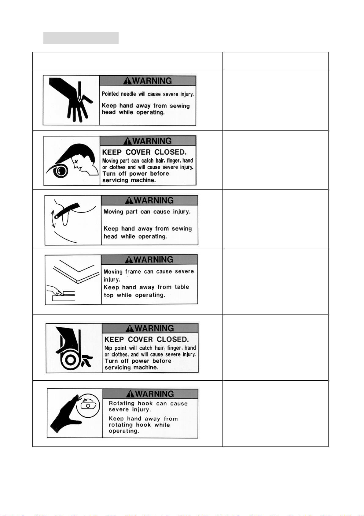
3.Warning Labels
GPay attention during operation to the parts labeled.
Warning Labels Contents
Needle Hazard Warning Lable
Hair Warning Label
Take-Up Lever Warning Label
Frame Warning Label
Hook Warning Label
1-5
Belt Warning Label

Chapter 2. Introduction
This chapter contains the following information.
1. Specification
2. Advantage
2-1

1. Specification
1) Design Capacity/Stitch Capacity : 30 designs /10 million stitches
2) Display : LCD 320 x 240 16bit Color LCD
3) Power Source : AC100V Single
AC200V Single
(+/-10%, 50/60Hz)
4) Power Consumption : 1KVA /Varies for each model
5) Temperature : 5 – 45 Degree Centigrade (Active)
-20 – 60 Degree Centigrade (Storage)
6) Humidity : 20 – 80 %RH, No condensation allowed
7) Grounding : Grounding resistance to be less than 100Ohm
(Type 3 grounding)
8) Main Motor : 200V AC Servo Motor
9) Pantograph Drive Motor : AC Servo Motor
10) Head Number : 1
11) Speed : 200 – 1200rpm
(Max Speed is defined for each model)
12) Needle Number : Max.15 (Sliding Head)
13) CF Card Slot : X 1
14) Trimmer Compatible : Mark 5
15) Thread Break Detection
16) USB Port : USB1.1 (USB Board required)
17) Networking System : Ethernet (Ethernet Board required)
18) COM Port : 9600 – 115200bps (COM Board required)
19) Capable to drive Cap Frames (Cylinder Bed Model)
20) Capable to drive borer
21) Compatible to Sequin Device (Factory Option)
22) Compatible to a Barcode Reader (Option)
23) Emergency Stop Switch (Factory Option)
2-2

2.Advantage
1) Easy Operation
The controller has a microcomputer and is designed for an embroidery machine.
More reliable than multipurpose control system.
Graphic User Interface with icons makes operating the machine easy.
2) High Speed Drive
The microcomputer chooses most efficient speed automatically(200-1200rpm).
*Max. Speed may vary for each model.
3) Quiet Drive
AC Servo driven main motor allows powerful and quiet drive.
It also allows accurate speed control and stop position.
AC Servo drives the pantograph at high speeds quietly.
4) Memory Capacity
The memory capacity is 10 million stitches and in 30 memory locations.
5) Design Information
Design Information such as total number of stitches, quantity produced, size,
Thumbnail of the design can be seen on the screen.
6) Networking
Optional Ethernet board allows the LAN networking of the machines.
Networked machines can share designs and monitored in real-time.
7) USB Port
Optional USB board allows a direct connection to the PC, receiving designs from a
PC.
8) USB Memory Slot
Read/load designs from the USB Memory. USB Memory hold more designs and
stitches than a floppy disk.
9) Rotation, Mirror, Scale of the design
The controller can rotate the design 90degrees/in 1degree steps and can create
mirror image of the design.
It also can scale the design length / width individually.
10) Automatic Origin Return
When a design is finished sewing, the pantograph returns to the start position of
the design automatically. Allowing repeat work to be efficient.
11) Automatic Appliqué Position
The pantograph moves out to the programmed position, making it easier to lay the
appliqué fabric correctly on the product. Can also be used be used to replace
frames.
2-3

12) Other Functions
a. The controller allows cycle embroidery 1-200 or infinite (Setting : 201)
b. Automatic design conversion for socks.
c. Automatic layout for the Matrix embroidery
Creates a pattern arrangement controlling the number of times a pattern
will sew horizontally and vertically and amount of space between each.
d. The colors (Needle No.) in a design can be easily changed and saved.
13) Start position
The start position of a pattern is saved.
14) Trace
The area to be sewn is shown on the screen and traced out by the pantograph.
15) Stitch Back Feature
Repairs stitches using the Stop key, stop the machine using the stop key, hold
down the stop key till the pantograph reaches the desired position, and then
let go.
Press it again to stop the pantograph.
16) Automatic speed control, Jump
The controller varies the speed of the machine automatically depending on the
setting and stitch length to have better stitch quality. The controller gives
automatic Jump Stitches as the stitch length reaches to set value. It also
creates higher stitch quality.
17) Float
The pantograph can be moved without sewing to have the designated position to
start sewing.
It also can move the pantograph directly to the designated position by typing
in the stitch count.
18) Error Code
Errors are displayed on the screen in icon form.
19) Stand-By(Resume)
The machine can be turned OFF in the middle of a design. The machine resumes in
the position where embroidery is stopped.
2-4

Chapter 3. Before Use
This chapter includes information on the following topics.
1. Automat
2. Turning ON /OFF the Machine
3. Origin Setting
4. Stand-by and Drive State
5.Switching Menu Icon Keys
6. Switching Screens
7. The Information on the Screen
8. The Information on the Extension Screen
9. Messages
10. Message to Start the Machine
11. Color Setting of the Display
3-1
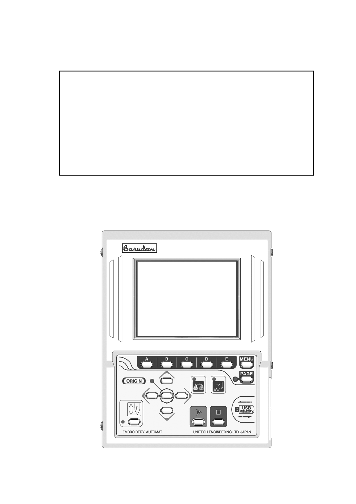
②
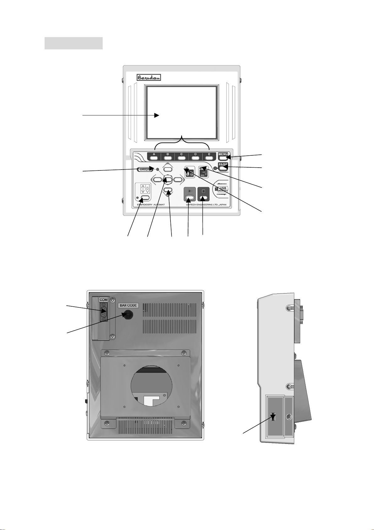
1. Automat
①
③
⑧
④
⑤
②
⑨
⑦
⑥
⑪
⑫
⑩
⑬
⑭
3-2
⑮

1. LCD Display
Shows machine status, icons, design information
*Refer to “Contents on the display”
2. Icon key – the A, B, C, D, E-keys
The operation buttons assigned to functions displayed by icons.
3. Origin LED
When lit the pantograph is located at the origin.
Blinks when the Jog Keys are assigned to other functions.
4. Origin Key
Moves the pantograph to the origin.
When the pantograph is located at the origin, it moves the pantograph to the
previous position in stand-by state, the position of the last stitch in
Drive mode.
5. Jog Keys
Moves pantograph. Single stroke gives 0.1mm movement. Holding the button moves
The pantograph in a continuous movement and the speed gradually increases.
Used to move the cursor for selecting.
6. Page Key
Switches screen
*Refer to “Paging Screen”
7. Menu Key
Switches the Menu Icon Keys
*Refer to switching the Menu Icon Keys
8. Drive Key
Places the machine in Drive mode, ready to sew.
9. Start Key
The machine starts sewing.
10. Stop Key
The machine stops sewing.
11. Float LED
Lit when the pantograph is moving through a pattern without sewing.
12. Teach LED
Lit when locating/changing existing function codes in a pattern.
13. COM (Serial) Por
This is to connect with RS-232 Cable.
This can be exchanged to LAN Card or USB Port.
14. PS / 2 Port
The PS/2 port for optional barcode reader.
Using barcode can skip some operations.
15. USB Memory Slot
The USB Memory slot
Designs are loaded/saved onto the USB Memory. It also loads the system
Software for the automat.
3-3
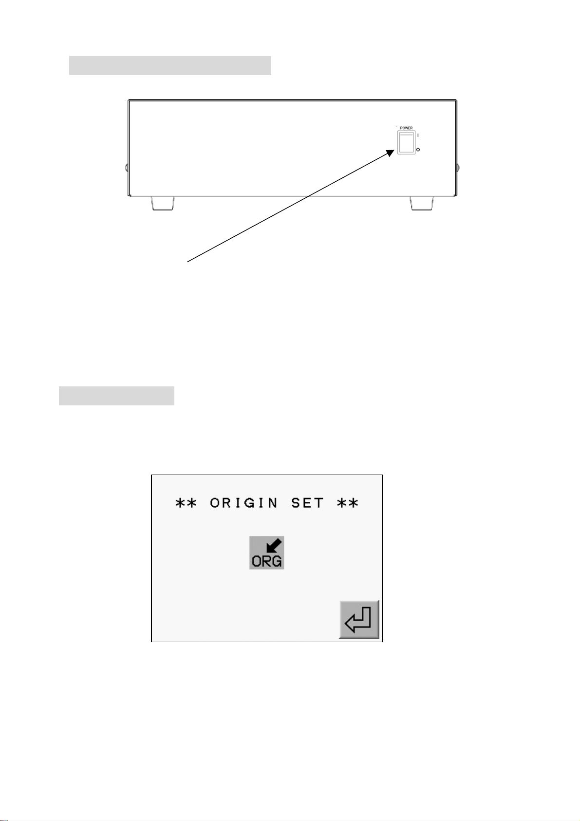
2.Turning the machin ON/OFF
POWER SOURCE SW
Turning the machine ON
Press POWER ON Switch.
Turning the machine OFF
Press POWER ON Switch to turn OFF.
3. Origin Set
When the machine is initially turned on the origin must be set.
1) Refer to “Turning ON/OFF the machine, turn ON the machine.
2) The display shows the screen below after showing BARUDAN logo.
Press the E-Key to move back the pantograph to the origin.
(A-Key) (B-Key) (C-Key) (D-Key) (E-Key)
*No operation would be allowed until origin setting finishes.
3-4
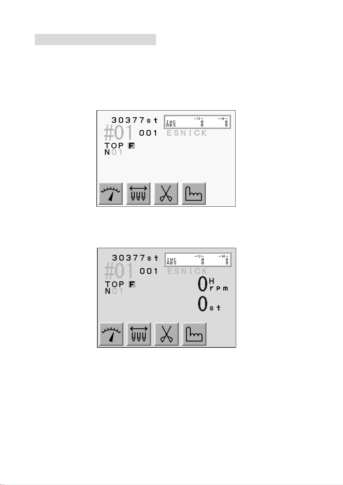
4.Stand-By and Drive Mode
The machine has two mode Stand-By, when it is not in a sewing mode but turned on
and the Drive mode, ready to begin sewing.
Refer to “Drive” in “Start Sewing”.
1) Stand-By mode : Usually machine is in the stand-by state when it is turned ON.
It is the state when sewing preparation takes place.
In this state, the design data can be selected and loaded.
Typical appearance of the stand-by state
2) Drive Mode : A design is chosen and it is ready to sew.
Typical appearance of the drive mode.
3-5
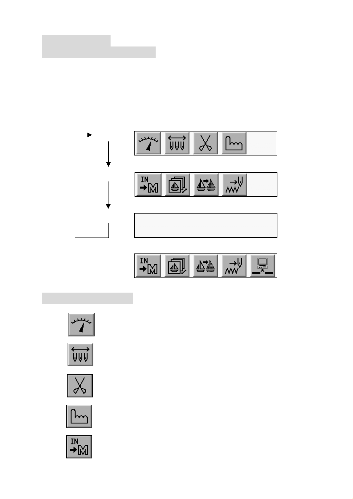
5.Menu Keys
5-1.Switching Menus
Menu keys (A - E) correspond to the icon commands directly above them on the LCD.
The Menu key moves to the next set of commands. The icons change accordingly,
while advancing though the various functions.
Press the menu key, to display the next set of commands (Menu 1 and Menu 2)
are displayed as shown below.
Note: If you selected one of the Menu Icon Keys and you want to quit it, pressing
The menu key exits the menu.
MENU1
MENU2
Sub MENU
When“Network”is being set in the machine,
MENU1
5-2 Menu Icon Keys
This explains all the Menu Icon Keys as shown below.
1) Speed Key
Changes the machine speed.
2) Needle Change Key
Manually changes the needle (Color).
3) Trimming Key
Manually trims thread.
4) Manual Key
Shows manual operation menu and parameter setting icon.
5) Memory In Key
Reads a Pattern in to the machine memory through the COM Connection.
3-6

6) Memory Key
Shows designs in the memory and CF card. Outputs the design.
Shows drive mode.
7) Teach Key
Lists the color change codes in the design and allows
them to be changed.
8) Float Key
Moves the pantograph through the design with stitich it.
9) Network Key
Reads design data from the server.
6.Switching the Screens
Press the Page Key to change screens.
When NOT in Drive Mode: ⇒ Basic Screen ⇒ Extension Screen 1 ⇒ Basic Screen ⇒
While IN Drive Mode: ⇒ Basic Screen ⇒ Extension Screen 1 ⇒ Extension Screen 2 ⇒
Basic Screen ⇒
Refer to “Screen Information” for screen contents.
1) Basic Screen
2) Extension Screen 1
Design Information such as total stitch count, next color change, estimated run time.
3-7
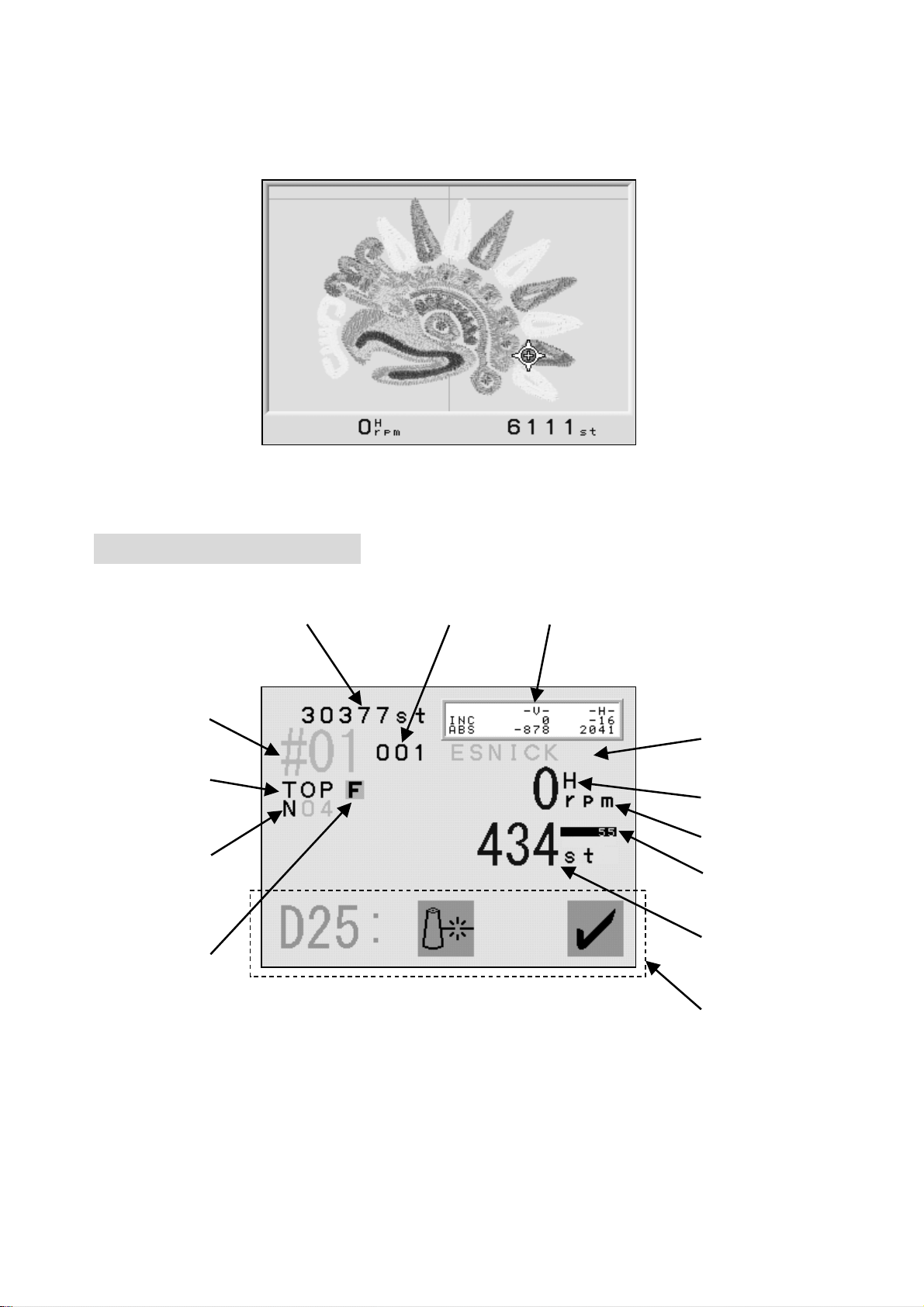
3) Extension Screen 2
Press Page Key twice to show the extension page 2. It shows the
design and current needle location as it is sewing, the machine speed,
and the total stitch count.
The Page Key shows the Basic Screen. Going back to the Stand-By mode
automatically switches the screen to the Basic Screen.
7.Screen Information
Basic Screen Information
⑪ ④ ⑦
①
②
⑤
⑨
⑧
⑥
⑫
⑩
③
⑬
*The screen shows design information for the currently selected design.
1. The Memory Location of the Design
The number blinks when there is no design in that memory location.
The number would be highlighted when the design is rotated, scaled or mirrored.
3-8
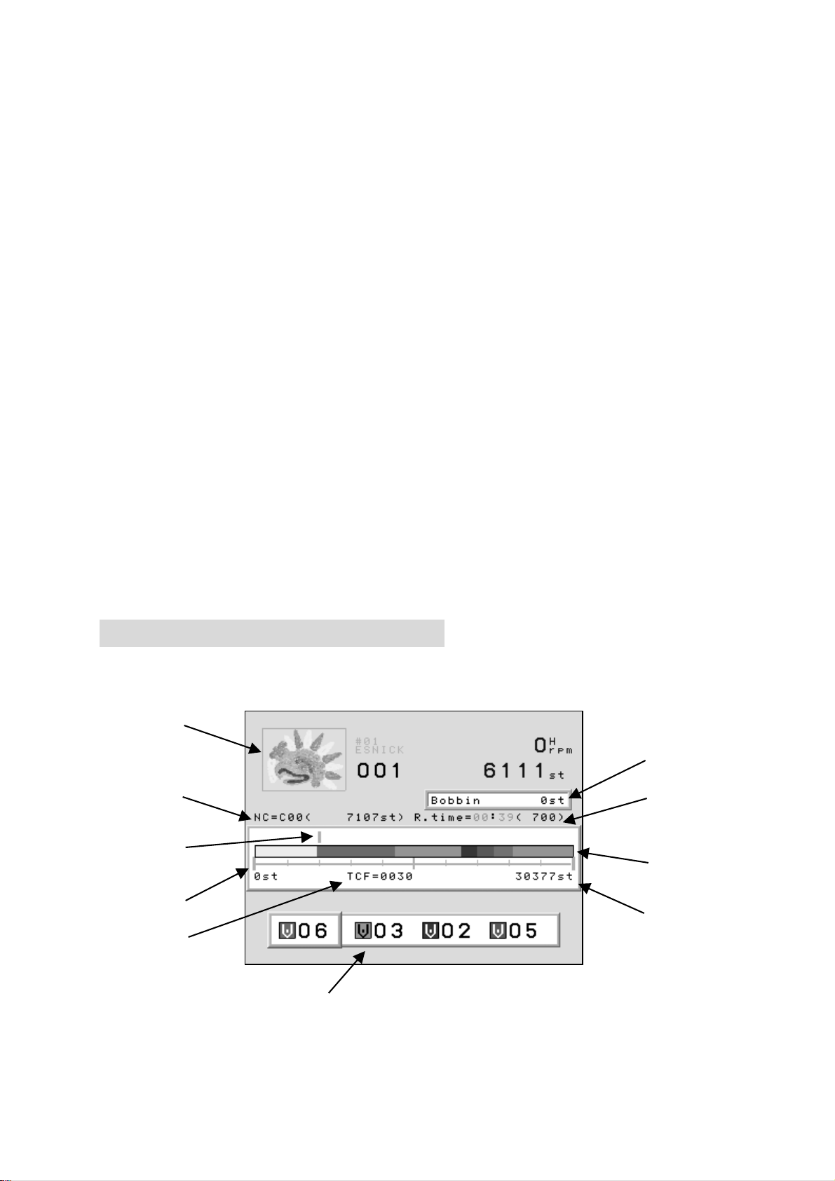
2. Design Name.
3. Programmed Rotation. (Can be changed in the Drive Condition Menu)
4. Programmed Repeats set in the Drive Condition.
5. Indicates the correct stop position when it shows “TOP”.
6. Indicates the needle No.
Shows “NO” when the position of the needle is incorrect.
7. It shows the distance the pantograph moved.
INC : The distance form the last stitch.
ABS : The distance from the start position.
8. Shows the speed of the machine when it is running.
9. Shows whether the data has High or Low speed Function.
10. Shows the current stitch count when in the Drive mode.
11. Total stitch count available in memory.
12. Shows the number of stitches backtracked.
Shows the amount stitches backtracked with thread break detection, Stitch
Back and Automending.
13. Displays menu icon or error messages.
8. Extension Screen Information
1) Extension Screen 1 information.
The Memory location, total number of stitche and the number of repetition
are shown same as on the basic screen.
⑨
⑧
① ②
④
⑤
③
⑥
⑦
⑩
*Shows information on the currently selected design.
*In the Stand-By mode, the speed and current stitch count are not shown.
3-9

1. Shows the stitch count where the next color change exists and the needle No.
2. Shows estimated run time and max. speed.
The run time is calculated from the remaining stitches and the sewing speed.
This is an estimated run time.
3. The progress scale.
4. Stitch Progress
5. Color change marker
6. Total stitch count.
7. Total number of color changes.
8. The remaining number of stitches before the machine will stop to change bobbin.
The Bobbin Counter feature must be turned on.
9. Thumbnail of the selected design.
The thumbnail reflects rotation and scale if programmed to the design.
10. Shows the next 3 color changes.
2) Extension screen 2 information
①
② ③
1. 3D thumbnail of the design.
The rotation, scale, satin stitch, sequin position are shown in the thumbnail.
2. Shows current speed.
3. The current stitch count.
3-10
9. Messages
Error messages display during operation display at the bottom of the basic screen.
For example, the figure below shows the error message for a thread break.
(A-Key) (B-Key) (C-Key) (D-Key) (E-Key)
Clearing the message
Press the E-Key or the Page Key to clear the message.
The A to D-Key are not available while a message appears on the screen.
First clear the message, before execute other functions.
Messages
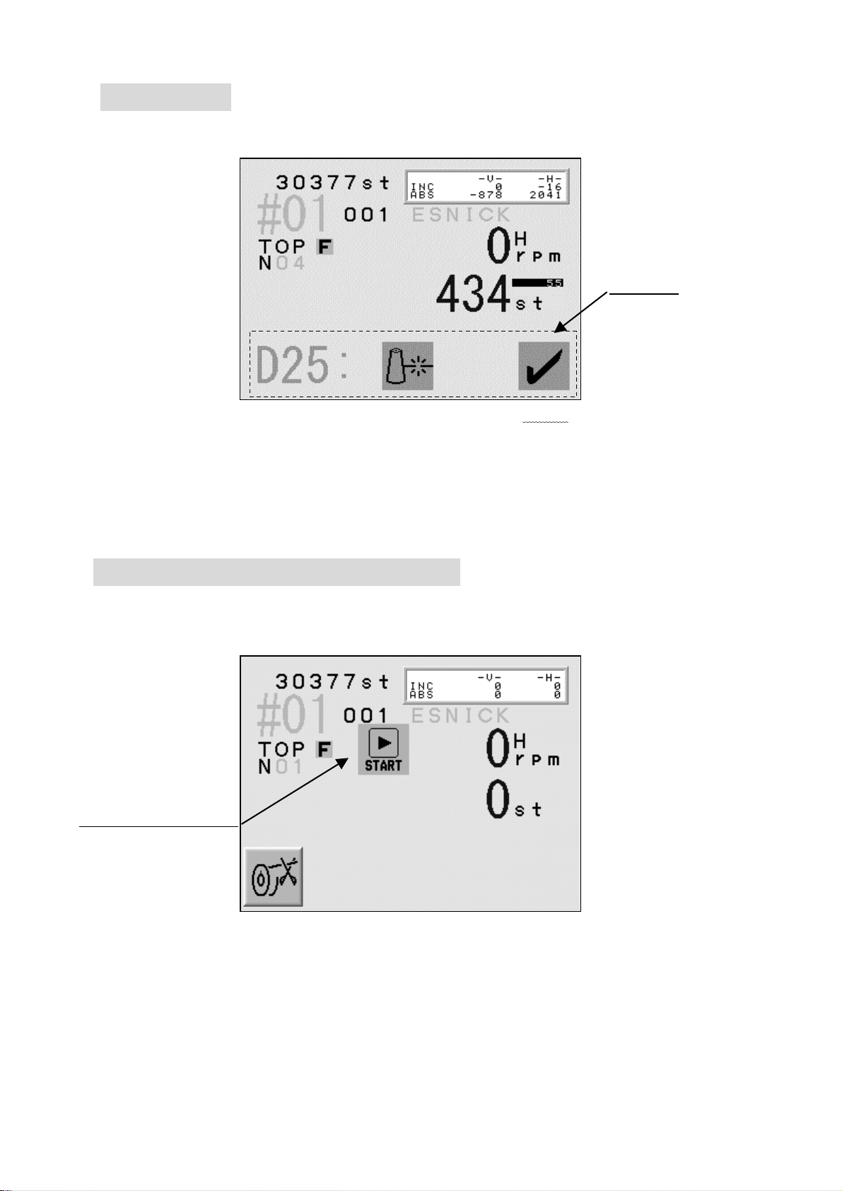
10. Message to Start the Machine
The icon for the Start Switch is shown below.
A little above from the center of the screen the icon for the Stop Switch appears.
Example : The Start Switch message for a manual trimming.
StartSwitch mmMessage
(A-Key) (B-Key) (C-Key) (D-Key) (E-Key)
3-11
11. Setting Colors on the Display
11-1. Jog Key operation
The Jog Keys move the cursor through the list.
The Jog Key chooses the color on the display.
Choose a column with up / down key。
Left / Right key switch the page
Move Up / Down the cursor with Up/Down Key
Move Left / Right the cursor
11-2. Changing the Display Color
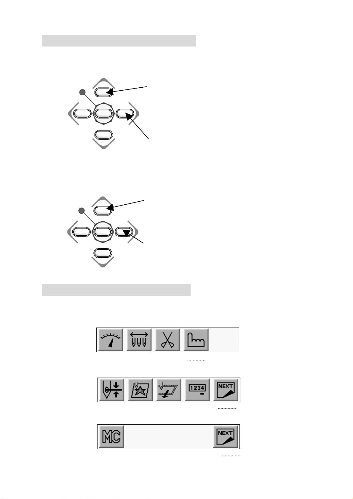
1) Press the Menu Key to display “Menu 1” as below.
2) Press the D-Key.
MENU 1
3) Press the E-Key.
4) Press the E-Key.
(A-Key) (B-Key) (C-Key) (D-Key) (E-Key)
(A-Key) (B-Key) (C-Key) (D-Key) (E-Key)
(A-Key) (B-Key) (C-Key) (D-Key) (E-Key)
3-12
5) Press the A-Key.
(A-Key) (B-Key) (C-Key) (D-Key) (E-Key)
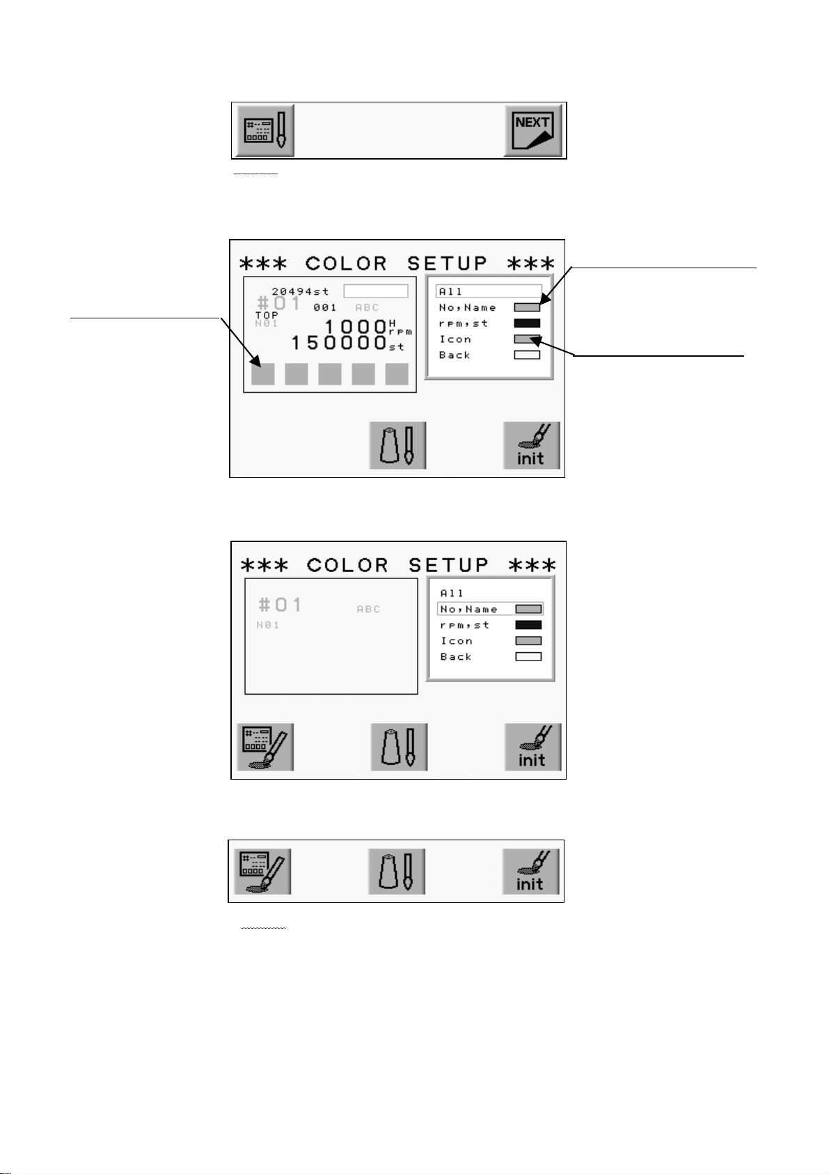
6) The Color Set-Up Menu displays.
Use the Jog Keys to select a color.
Color for the chosen item
The screen thumbnail
Set Color for Each Item
(A-Key) (B-Key) (C-Key) (D-Key) (E-Key)
7) Choose the item.
(A-Key) (B-Key) (C-Key) (D-Key) (E-Key)
8) Press the A-Key.
(A-Key) (B-Key) (C-Key) (D-Key) (E-Key)
3-13
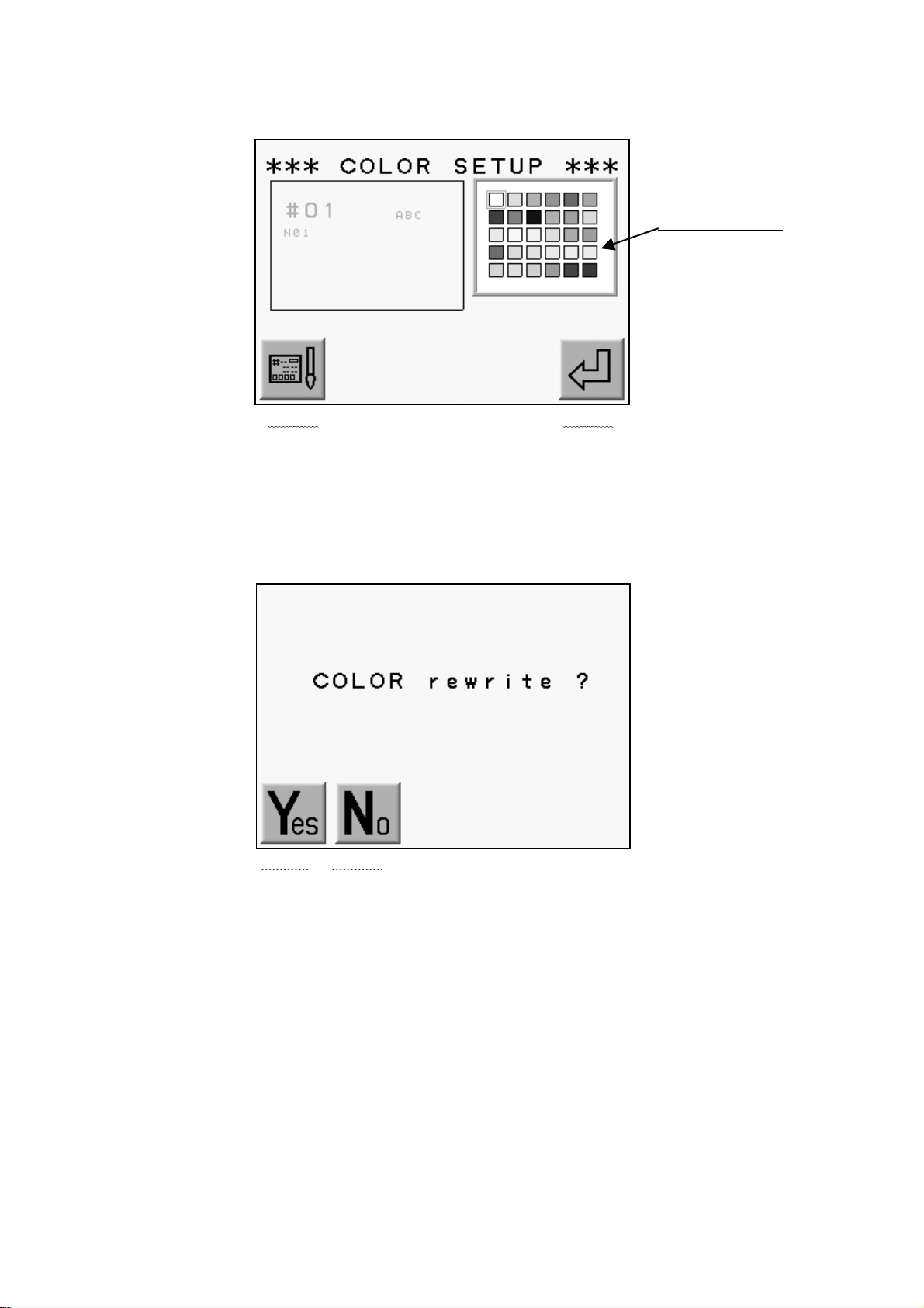
9) The color chart displays.
Use the Jog Keys to select a color.
The Color Chart
(A-Key) (B-Key) (C-Key) (D-Key) (E-Key)
A-Key to goes back to previous screen.
Press the E-Key to save the change and go back to previous screen.
10) Press the MENU Key to go out from the Color Set-Up Menu.
11) Press the A-Key to Save changes.
(A-Key) (B-Key) (C-Key) (D-Key) (E-Key)
Press the B-Key to cancel the changes.
3-14
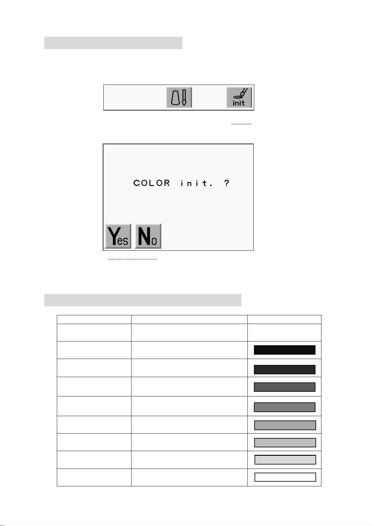
11-3. Initializing the Color
Initializing the color display.
1) refer to “Changing the Color in the Display” and find the Color Set-Up Menu.
2) Press and hold the E-Key for 2 short beeps.
(A-Key) (B-Key) (C-Key) (D-Key) (E-Key)
3) Press the A-Key to start initialization.
(A-Key) (B-Key) (C-Key) (D-Key) (E-Key)
Press the B-Key to Cancel the initialization.
11-4. Items that can have colors changed
Item Description Default Color
All
No, Name
Shows all the items in the thumb
nail in set color
Memory Location, Design file nam
e, Needle No.
rpm, st Speed and Stitch Count
Icon Icon
Back Background
(Visual)
(Drive )
(Float )
(NET AB)
The background clor of
design thumbnail
The back ground color for Drive
Mode
The background color for
Float
The back ground color for
Time-Out in the Network System
3-15

11-5.Changing Memory Design Color(Color Edit)
List the color for each code.
* Changes the color of the memory design bitmap and visual display.
1) Refer to “Changing the Color in the Display” and go to the color Setup Menu.
2) Press the C-Key.
(A-Key) (B-Key) (C-Key) (D-Key) (E-Key)
3) The color list for each code displays.
Use the Jog Keys to select the needle color you want to change.
Chosen Needle Color
(A-Key) (B-Key) (C-Key) (D-Key) (E-Key)
Press the C-Key to go back to the display color setting screen.
* C01 ~ C15 = Needle Thread Colors
Optional Machine Device Colors:
SQ = Sequin Color
L1 ~ L6 = Chenille Looper Colors
B-L and B-R = Tape or Cording Colors. T= Tape, C = Cord.
(Note: T and C settings can be swapped by pressing and holding the Origin key)
4) Press the D-Key.
(A-Key) (B-Key) (C-Key) (D-Key) (E-Key)
3-16
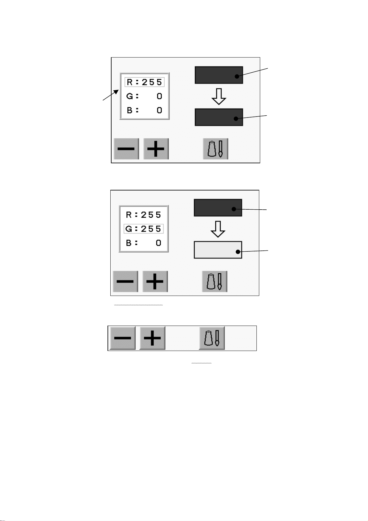
5) Change the color.
Use the jog key and choose 3 primary colors, “R””G””B”.
Original color
3 primary colors
New color
6) Change the value using the A/B-Keys.
The color pallet color changes depend on the entered value.
Original color
New color
(A-Key) (B-Key) (C-Key) (D-Key) (E-Key)
7) Press the D-Key to go back to the previous screen.
(A-Key) (B-Key) (C-Key) (D-Key) (E-Key)
3-17
 Loading...