


01.08.00 - GB
22
INSTRUCTION MANUAL
FOR INSTALLATION,
MAINTENANCE
AND USE
ELECTRIC KETTLES 55LT.
286.811
01.08.00 – GB

01.08.00 - GB
23
INDEX
Part 1: General reminders and notes
1.1.
General reminders
24
1.2.
Technical data
24
1.3.
Construction
25
1.4.
Laws, technical prescriptions and directives
25
1.5.
Special requirements for the installation site
25
Part 2: Positioning, installation and maintenance
2.1.
Positioning
26
2.2.
Installation
26
2.2.1.
Electrical connections and equipotential bonding
26
2.2.2.
Connection to waterworks
27
2.3.
Commissioning and testing
27
2.4.
Maintenance of the appliance
27
2.4.1.
Possible failures and their elimination
28
Part 3: Use and cleaning
3.1.
Warnings and hints for user
28
3.2.
Instructions for use
28
3.2.1.
Filling the jacket
29
3.2.2.
Switch on, start of cooking and switch off
29
3.3.
Cleaning and care of the appliance
29
3.3.1.
Daily cleaning
30
3.4.
Special procedures in case of long inactivity
30
3.5.
Special procedures in case of failures
30
3.6.
How to proceed, if …
30
Part 4: Figures and details
4.1.
Wiring diagram Mod. 55 lt
41
4.2.
View of appliance
43
4.3.
Controls
44

01.08.00 - GB
24
1.1. GENERAL REMINDERS
Read the warnings contained in this manual carefully as they provide important information concerning
safety during the installation, use and maintenance of the appliance.
Keep these instructions carefully!
Only personnel trained for its specific use should use the equipment.
Keep the appliance under control during use.
The appliance should be used only for the purpose for which it has been specifically designed; other
uses are improper and hence dangerous.
During operation surfaces can become hot and require special operation.
Unplug the appliance in case of failures or improper operation.
Apply exclusively to a service centre for repairs or maintenance.
Any important information about the appliance required for technical service is contained in the technical
data plate (see figure “View of appliance”).
If technical assistance is required, the trouble must be described in as much detail as possible, so that a
service technician will be able to understand the nature of the problem.
Gloves should be worn to protect the hands during installation and maintenance operations.
Warning! : Follow the fire prevention regulations very carefully.
1.2. TECHNICAL DATA
Specifications
Description
Unit of
measurement
286811
Width (A)
mm
800
Depth (B)
mm
700
Height (C)
mm
900
Vat diameter
mm
400
Vat height
mm
450
Total volume
l
58
Usable volume
l
50
Voltage/Input
3N AC 400V / 50 Hz
Power
kW
9
Power cable
mm²
Hot water connection
mm
10
Cold water connection
mm
10
Water pressure
kPa
50 – 300
Pressure
bar
0,5

01.08.00 - GB
25
1.3. CONSTRUCTION
Main structure in AISI 430 with 4 adjustable height feet.
Panels in stainless steel AISI 304, thickness 10-12/10.
Cooking vat in stainless steel AISI 316, thickness 20/10.
Chrome-plated brass drainage tap.
Lid in stainless steel, hinged and spring balanced in all opening positions.
Jacket and lining in stainless steel AISI 304, thickness 15-20/10.
Heating system comprising shielded heating elements made from “Incoloy-800” alloy with boiler and
steam circulation.
Jacket pressure is controlled by a safety valve set at 0.5 bar; the appliance is equipped with an analogue
pressure gauge.
The cold water connection is 10 mm.
The hot water connection is 10 mm.
Safety thermostat to interrupt operation automatically in case of failures.
The appliance is equipped with a three-position selector with three heating functions:
position “0” Heating not activated
position “I” Reduced power 50%
position “2” Full power 100%
Operating thermostat.
1.4. LAWS, TECHNICAL PRESCRIPTIONS AND DIRECTIVES
When installing the appliance it is necessary to follow and comply with the following regulations:
current regulations on the matter;
any hygienic-sanitary regulations concerning cooking environments;
municipal and/or territorial building regulations and fire prevention prescriptions;
current accident prevention guidelines;
electricity board regulations concerning safety;
the regulations of the electrical power supply company or agency;
any other local prescriptions.
1.5. SPECIAL REQUIREMENTS FOR THE INSTALLATION SITE
The room in which the appliance is to operate must be well ventilated.
In addition, it is good policy to locate the appliance under an extractor hood so that cooking vapours can
be removed rapidly and continuously.
Current regulations require the installation of a multiple pole switch between the appliance and the
electrical power supply; the switch must have a contact gap of least 3 mm on each pole.
This appliance requires two water connections: one for hot and one for cold water. Each line must be
fitted with an on-off valve.
Warning! : The electrical isolating switch and the water shutoff valves must both be located near
to the appliance, within easy reach for the user.

01.08.00 - GB
26
2.1. POSTIONING
Remove all the packaging and check that the appliance is in perfect conditions. In case of visible
damage, do not connect the appliance and notify the sales point immediately.
Remove the PVC protection from the panels.
Dispose of packaging according to regulations. Generally material is divided according to composition
and should be delivered to the waste disposal service.
There are no special instructions regarding distances from other appliances or walls, however it is
advisable to maintain a sufficient distance to allow any servicing operations to be performed. In the event
the appliance should be installed in direct contact with inflammable walls, it is advisable to fit suitable
heat insulation.
The appliance must stand level. Small differences in level can be eliminated by screwing or unscrewing
the adjustable feet: A significantly uneven or sloping stance can affect the operation of the appliance
adversely.
2.2. INSTALLATION
Warning! : Only qualified technicians must perform the installation, maintenance and test of the
appliance.
Warning! : Before connecting any parts of the appliance to supplies, make sure that the latter is
equivalent the requirements stated in the technical data plate, if the appliance has
been designed for these supplies.
2.2.1. ELECTRICAL CONNECTIONS AND EQUIPOTENTIAL BONDING
Warning! : The appliance is supplied to operate according to the power supply indicated on the
data plate.
As mentioned, the appliance must be connected to the power supply by way of a multiple pole main
isolating switch and protection device that must be proportioned to the power of the appliance (1 mA per
kW of rated power).
The earthing system must be efficient.
As this appliance is type X equipment (delivery without power cable and plug), the cable and other
hardware needed to make the connection to the electrical power supply must be provided by the
installer.
The power cable shall be of the kind described in the paragraph “Technical data" and shall be resistant
to oil.
The power terminal board can be reached by removing the lower front panel (unloose the screws). The
cable fastener is on the lower right-hand side.
The cable must be fed in from beneath the clamp. The individual wires are then fastened to the
corresponding terminals of the terminal board. The earth wire must be longer than the other wires, so
that in the event of the cable being jerked or the clamp broken, the live wires will disconnect first. Lock
the cord fastener.
The appliance must incorporate an equipotential system.
Connect the terminal on the lower right-hand side marked with the international symbol a connector with a
nominal cross section <10 mm2. All the appliances installed and the earth system of the building shall be
connected like this.

01.08.00 - GB
27
2.2.2. CONNECTION TO WATERWORKS
Water inlet pressure must be between 50 and 300 kPa, otherwise install a pressure regulator on the line
before the appliance.
Install a cut-off valve for each supply on the line before the appliance.
Water connections to 10 mm are fitted in the lower part on the right-hand side of the appliance.
Make connections according to regulations currently in force.
2.3. COMMISSIONING AND TESTING
Once all the connections have been made, the appliance and the overall installation must be checked
following the directions given in this manual.
Check in particular:
that the protective film has been removed from the external surfaces;
that the lower front panel removed for the electrical connection of the appliance has been fitted back
into position;
that connections have been made in accordance with the requirements and directions indicated in
this manual;
that all safety requirements in current standards, statutory regulations and directives have been met;
that the water connections are leak-free;
that the electrical connection has been performed according to standards.
In addition, check that once the appliance has been installed, the power cord is neither subject to stretch
nor in contact with nor surfaces.
Now proceed to light the appliance as directed in the instructions for use.
While the appliance is in use, voltage should not differ from the nominal voltage more than +/- 10%.
The test report must be completed in full and submitted to the customer who should then sign in
acceptance. With effect from this moment, the appliance is covered by the manufacturer’s warranty.
2.4. MAINTENANCE OF THE APPLIANCE
Warning! : All maintenance operations shall only be performed by a technically qualified service
centre!
To ensure correct and safe operation, the appliance must be inspected and serviced at least once a year
only. Maintenance includes also controlling the components and tear of pipes, feeding pipes, electrical
components etc.
It is advisable to replace worn components during maintenance operations to avoid the need for other
maintenance calls and unexpected failures.
It is also advisable to apply for a maintenance contract with the customer.

01.08.00 - GB
28
2.4.1. POSSIBLE FAILURES AND THEIR ELIMINATION
Warning! : Only technically qualified service centres can perform the operations described
below!
Warning! : Before resetting the safety thermostat, it is always necessary to eliminate the
problem causing its activation!
Problem and possible cause
Access to components and operation
The content of the vat does not heat up:
the safety thermostat has been
activated;
the heating elements have a failure;
selector/switch failure.
Safety thermostat
Remove the lower, right front panel, unloose the screws and
remove the support of the connector-block.
The safety thermostat can be reached once the lid of the
connector-block has been removed.
Heating elements
The heating elements can be reached once the lower front
panel has been removed.
Selector/switch
To reach the selector/switch, remove the upper front panel.
Ignition plug and thermocouple
Remove the lower front panel.
3.1. WARNINGS AND HINTS FOR USER
This manual contains all the instructions required for a proper and safe use of our appliances.
Keep the manual in a safe place for future consultation!
This appliance is for catering use, hence they must be used only by trained kitchen staff.
The appliance must always be kept under control during use.
Warning! : The manufacturer shall not be held responsible for injuries or damage due to the non-
compliance with safety rules or an improper use of the appliance by the operator.
Some improper operating conditions may even be caused by an improper use of the appliance, therefore
it is important to train personnel properly.
All the installation and maintenance operations must be performed by fitters who are members of
an official register.
Respect the periods required for maintenance. With this is mind, customers are recommended to sign a
service agreement.
In case of failures concerning the appliance, all outputs (electrical power supply and water) must be cut
off instantly.
In case of recurrent failures, contact a service technician.
3.2. INSTRUCTIONS FOR USE
Before cooking with the appliance for the first time, wash the interior of the cooking vat thoroughly.
Warning! : Fill the cooking vat up to a maximum of 40 mm under the overflow border, according
to the maximum level mark, including the food to be cooked.
Warning! : Before filling the vat, always check that the drainage tap is closed.

01.08.00 - GB
29
3.2.1. FILLING THE JACKET
Warning! : The water level in the jacket must be checked each time before lighting.
Warning! : It is advisable to use softened water to fill the jacket!
Open the level tap on the front of the appliance.
Unscrew the filling cap on the safety valve unit. The latter is on the right of the appliance surface (see
figure “Size of appliance and position of connections ”).
Fill with softened water (the capacity of the jacket is stated in the paragraph “Technical data”).
When water flows out of the level tap, close it and screw back on the safety unit cap.
3.2.2. SWITCHING ON, START COOKING AND SWITCHING OFF
Fill the vat with hot or cold water, according to need, using the tap that the appliance is equipped with.
The appliance has a three-position selector to start cooking functions (see figure “Controls").
Here is a list of the procedures for a safe and correct use of the appliance.
Energising the unit:
Connect the appliance by turning on the main switch installed before it.
3.3. CLEANING AND CARE OF THE APPLIANCE
Do not use aggressive substances or abrasive detergents when cleaning the stainless steel
components.
Avoid using metal pads of the steel parts as they may cause rust. For the same reason, avoid contact
with materials containing iron.
Do not use sandpaper or abrasive paper for cleaning; in special cases use a powder pumice stone.
In case of particularly resistant dirt, it is advisable to use abrasive sponges (e.g. Scotch-Brite).
It is advisable to clean the appliance only once it has cooled down.
Start of cooking:
Turn the selector from position “0” to one of the heating positions according to cooking requirements.
The green light turns on automatically.
Generally cooking is started with the selector in position “2”; once the vat has reached cooking
temperature, turn the selector to “1” to maintain it.
Set the operating thermostat knob on the desired temperature between 40 and 100°C.
Heating will start and the orange light will turn on automatically.
The orange light will turn off as soon as the set temperature has been reached.
To make water boil quickly, turn the knob over the temperature of 100°C.
Heating elements operate continuously.
By turning the selector from position “2” to “1”, it is possible to keep the water boiling and use less
power.

01.08.00 - GB
30
3.3.1. DAILY CLEANING
Warning! : When cleaning the appliance never use direct jets of water to prevent infiltration of
the liquid and damage to components.
Clean the cooking vat with water and a detergent, rinse thoroughly and dry well with a soft cloth.
External surfaces should be washed down using a sponge, and hot water with a suitable proprietary
cleaner addend.
Rinse always thoroughly and dry with a soft cloth.
3.4. SPECIAL PROCEDURES IN CASE OF PROLONGED INACTIVITY
If the appliance is to stand idle for any length of time (e.g. holidays or seasonal closing), it must be
cleaned thoroughly, leaving not traces of food or dirt.
Leave the lid open so that air can circulate inside the vat.
For added care after cleaning, the external surfaces can be protected by applying a proprietary metal
polish.
Be absolutely sure to shut off all utilities (electrical power supply and water).
Air the room appropriately.
3.5. SPECIAL PROCEDURES IN CASE OF FAILURES
If the appliance should not work properly during use, turn it off immediately and close or cut off all
supplies (electrical power supply and water).
Apply to a service centre for help.
3.6. HOW TO PROCEED, IF …
Warning! : Problems and failures may occur even when the appliance is used properly. Here is a
list of the mist probably situations and controls that the operator should perform to
avoid applying to a service centre unnecessarily.
If the problem is not solved after the necessary controls, turn off the appliance immediately,
unplug it, cut off any supplies and apply to a service centre.
… the vat contents do not heat
up:
check that the power ON/OFF switch installed before the
appliance is on;
otherwise turn off the appliance and apply to a service centre, as
the safety thermostat may have been activated due to an excess of
temperature in the cooking vat. This occurs especially when the
appliance is turned on and the vat and/or the jacket is/are empty.
The manufacturer shall not be held responsible nor has any warranty commitments
for damage caused by non-compliance with prescriptions or by installation not in
conformity with instructions.
The same applies in case of improper use or different application by the operator.

01.08.00
41
4.1. SCHEMA ELETTRICO MOD. 50 LT. 3N/PE AC 400V
LEGENDA:
mA
Morsettiera arrivo linea
SL
Centralina controllo livello
F1
Fusibile 3,15 A-T
TS
Termostato di sicurezza
SE
Selettore riscaldamento min-max
TL
Termostato di lavoro
L1
Lampada spia verde presenza tensione
C1
Teleruttore minimo
L2
Lampada spia arancione riscaldamento
RM
Relè di massimo
LR
Lampada led spia arancione riserva acqua
R1
Resistenza trifase (230V)
LA
Lampada led spia rossa mancanza acqua
B
Bulbo termostato di sicurezza
4.1. WIRING DIAGRAM MOD. 50 LT. 3N/PE AC 400V
LEGEND:
mA
End line terminal board
SL
Level control device
F1
Fuse 3,15 A-T
TS
Safety thermostat
SE
Selector
TL
Operating thermostat
L1
Green warning light
C1
Electromagnetic switch min.
L2
Heating on signal-lamp
RM
Relay for max.
LR
Orange lamp warning light failing water in the jacket
R1
Heating element (230V)
LA
Red lamp warning light in the jacket
B
Sensor for safety thermostat
4.1. SCHEMA ELECTRIQUE MOD. 50 LT. 3N/PE AC 400V
LEGENDE:
mA
Bornier arrivée ligne
SL
Fiche niveau
F1
Fusible 3,15 A-T
TS
Thermostat de sécurité
SE
Sélecteur
TL
Thermostat de travail
L1
Lampe témoin verte de tension
C1
Télérupteur minimum
L2
Témoin lumineux chauffage
RM
Relais pour maximum
LR
Lampe témoin orange riserve H20 double paroi
R1
Résistance (230V)
LA
Lampe témoin rouge alarme manque H20 doubler
paroi
B
Bulbe pour thermostat securite’
4.1. ELEKTRISCHER SCHALTPLAN MOD. 50 LT. 3N/PE AC 400V
LEGENDE:
mA
Netzanschlußklemme
SL
Platine für Niveaukontrolle
F1
Schmelzsicherung 3,15 A-T
TS
Sicherheitstemperaturbegrenzer
SE
Stellen
TL
Thermostat
L1
Grüne Signalleuchte der Spannung
C1
Schaltschütz min.
L2
Signalleuchte Heizung in Betrieb
RM
Relais max.
LR
Wasser-reserve Orange Signalleuchte
R1
Heizelement (230V)
LA
Rot Signalleuchte Alarm Mangel H20 im
Zwischenraum
B
Sensor fur sicherheitstemp.
4.1. ESQUEMA ELÉCTRICO MOD. 50 LT. 3N/PE AC 400V
LEYENDA:
mA
Tablero de bornes
SL
Tarjeta control nivel
F1
Fusible 3,15 A-T
TS
Termostato de seguridad
SE
Selector
TL
Termostato de funcionamiento
L1
Luz testigo verde de tension
C1
Telerruptor min.
L2
Luz testigo calentamiento
RM
Relé por max.
LR
Luz testigo anaranjada reserva H2O doble pared
R1
Resistencia (230V)
LA
Luz testigo roja alarma falta H20 doble pared
B
Bulbo x termostato de seguridad

01.08.00
42

01.08.00
43
4.1.1. MOD. 50 LT. OPTIONAL PAAR1014 3N/PE AC 400V (carico automatico intercap.)
LEGENDA:
mA
Morsettiera arrivo linea
S1
Elettrovalvola carico intercapedine (OPTIONAL)
F1
Fusibile 3,15 A-T
TS
Termostato di sicurezza
SE
Selettore riscaldamento min-max
TL
Termostato di lavoro
L1
Lampada spia verde presenza tensione
C1
Teleruttore minimo
L2
Lampada spia arancione riscaldamento
RM
Relè di massimo
LR
Lampada led spia arancione riserva acqua
R1
Resistenza trifase (230V)
LA
Lampada led spia rossa mancanza acqua
B
Bulbo termostato di sicurezza
SL
Centralina controllo livello
4.1.1. WIRING DIAGRAM MOD. 50 LT. OPTIONAL PAAR1014 3N/PE AC 400V
LEGEND:
mA
End line terminal board
S1
Jacket filling solenoid valve
F1
Fuse 3,15 A-T
TS
Safety thermostat
SE
Selector
TL
Operating thermostat
L1
Green warning light
C1
Electromagnetic switch min.
L2
Heating on signal-lamp
RM
Relay for max.
LR
Orange lamp warning light failing water in the jacket
R1
Heating element (230V)
LA
Red lamp warning light in the jacket
B
Sensor for safety thermostat
SL
Level control device
4.1.1. SCHEMA ELECTRIQUE MOD. 50 LT. OPTIONAL PAAR1014 3N/PE AC 400V
LEGENDE:
mA
Bornier arrivée ligne
S1
Electrovanne chargement double paroi
F1
Fusible 3,15 A-T
TS
Thermostat de sécurité
SE
Sélecteur
TL
Thermostat de travail
L1
Lampe témoin verte de tension
C1
Télérupteur minimum
L2
Témoin lumineux chauffage
RM
Relais pour maximum
LR
Lampe témoin orange riserve H20 double paroi
R1
Résistance (230V)
LA
Lampe témoin rouge alarme manque H20 doubler
paroi
B
Bulbe pour thermostat securite’
SL
Fiche niveau
4.1.1. ELEKTRISCHER SCHALTPLAN MOD. 50 LT. OPTIONAL PAAR1014 3N/PE AC 400V
LEGENDE:
mA
Netzanschlußklemme
S1
Magnetventil Zwischenraums
F1
Schmelzsicherung 3,15 A-T
TS
Sicherheitstemperaturbegrenzer
SE
Stellen
TL
Thermostat
L1
Grüne Signalleuchte der Spannung
C1
Schaltschütz min.
L2
Signalleuchte Heizung in Betrieb
RM
Relais max.
LR
Wasser-reserve Orange Signalleuchte
R1
Heizelement (230V)
LA
Rot Signalleuchte Alarm Mangel H20 im
Zwischenraum
B
Sensor fur sicherheitstemp.
SL
Platine für Niveaukontrolle
4.1.1. ESQUEMA ELÉCTRICO MOD. 50 LT. OPTIONAL PAAR1014 3N/PE AC 400V
LEYENDA:
mA
Tablero de bornes
S1
Elettrov.carga autom.intercambiador
F1
Fusible 3,15 A-T
TS
Termostato de seguridad
SE
Selector
TL
Termostato de funcionamiento
L1
Luz testigo verde de tension
C1
Telerruptor min.
L2
Luz testigo calentamiento
RM
Relé por max.
LR
Luz testigo anaranjada reserva H2O doble pared
R1
Resistencia (230V)
LA
Luz testigo roja alarma falta H20 doble pared
B
Bulbo x termostato de seguridad
SL
Tarjeta control nivel

01.08.00
44
01.08.00
45
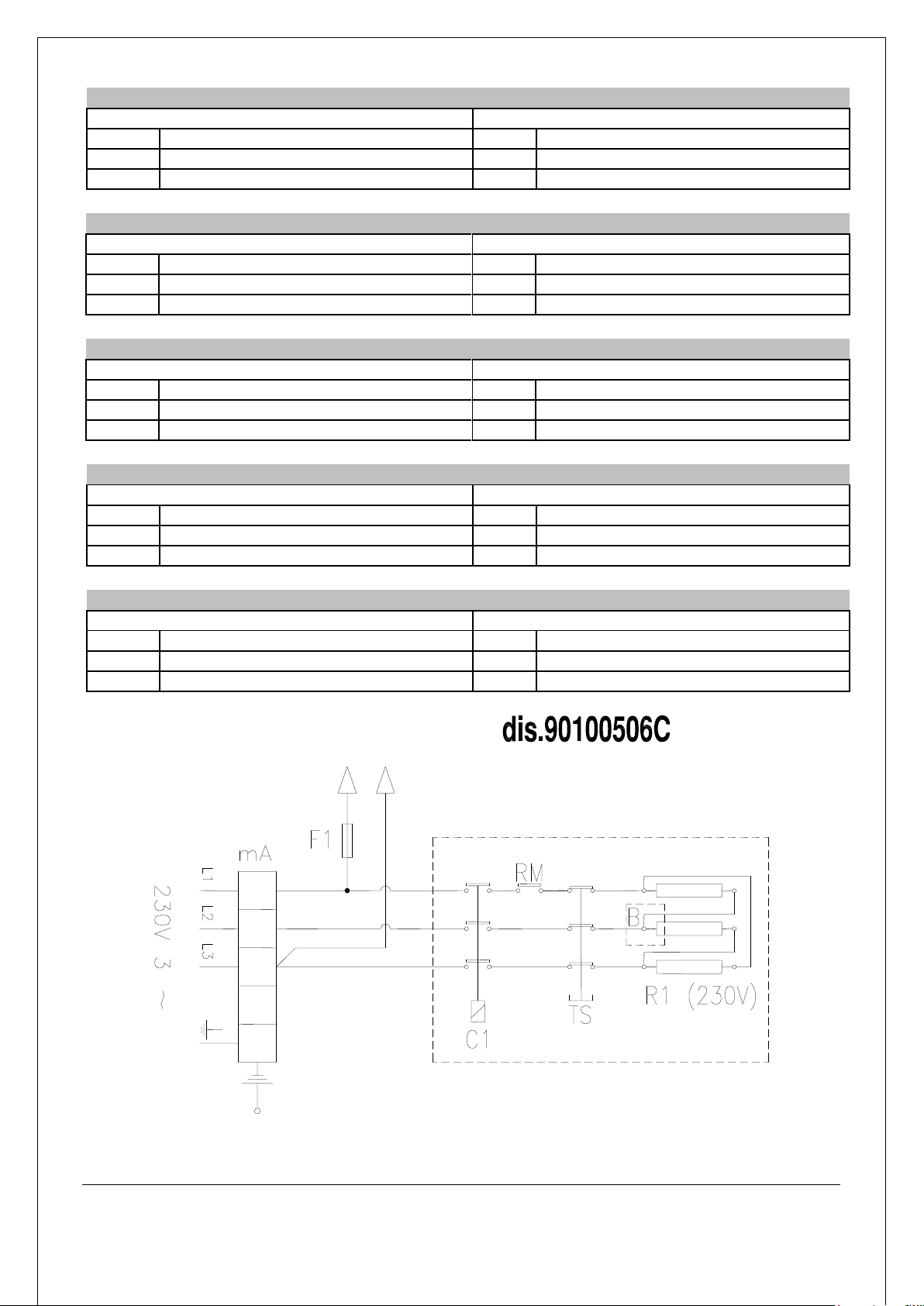
4.1.2. SCHEMA ELETTRICO MOD. 50 LT. 3/PE AC 230V
LEGENDA:
mA
Morsettiera arrivo linea
RM
Relè di massimo
F1
Fusibile 3,15 A-T
TS
Termostato di sicurezza
C1
Teleruttore minimo
R1
Resistenza trifase (230V)
4.1.2. WIRING DIAGRAM MOD. 50 LT. 3/PE AC 230V
LEGEND:
mA
End line terminal board
RM
Relay for max.
F1
Fuse 3,15 A-T
TS
Safety thermostat
C1
Electromagnetic switch min.
R1
Heating element (230V)
4.1.2. SCHEMA ELECTRIQUE MOD. 50 LT. 3/PE AC 230V
LEGENDE:
mA
Bornier arrivée ligne
RM
Relais pour maximum
F1
Fusible 3,15 A-T
TS
Thermostat de sécurité
C1
Télérupteur minimum
R1
Résistance (230V)
4.1.2. ELEKTRISCHER SCHALTPLAN MOD. 50 LT. 3/PE AC 230V
LEGENDE:
mA
Netzanschlußklemme
RM
Relais max.
F1
Schmelzsicherung 3,15 A-T
TS
Sicherheitstemperaturbegrenzer
C1
Schaltschütz min.
R1
Heizelement (230V)
4.1.2. ESQUEMA ELÉCTRICO MOD. 50 LT. 3/PE AC 230V
LEYENDA:
mA
Tablero de bornes
RM
Relé por max.
F1
Fusible 3,15 A-T
TS
Termostato de seguridad
C1
Telerruptor min.
R1
Resistencia (230V)

01.08.00
46
4.1.3. SCHEMA ELETTRICO MOD. 50 LT. 3/PE AC 440V
LEGENDA:
mA
Morsettiera arrivo linea
RM
Relè di massimo
TR
Trasformatore 440-480/230V
TS
Termostato di sicurezza
F1
Fusibile 3,15 A-T
R1
Resistenza trifase (254V)
C1
Teleruttore minimo
B
Bulbo termostato di sicurezza
4.1.3. WIRING DIAGRAM MOD. 50 LT. 3/PE AC 440V
LEGEND:
mA
End line terminal board
RM
Relay for max.
TR
Transformer 440-480/230V
TS
Safety thermostat
F1
Fuse 3,15 A-T
R1
Heating element (254V)
C1
Electromagnetic switch min.
B
Sensor for safety thermostat
4.1.3. SCHEMA ELECTRIQUE MOD. 50 LT. 3/PE AC 440V
LEGENDE:
mA
Bornier arrivée ligne
RM
Relais pour maximum
TR
Transformateur 440-480/230V
TS
Thermostat de sécurité
F1
Fusible 3,15 A-T
R1
Résistance (254V)
C1
Télérupteur minimum
B
Bulbe pour thermostat securite’
4.1.3. ELEKTRISCHER SCHALTPLAN MOD. 50 LT. 3/PE AC 440V
LEGENDE:
mA
Netzanschlußklemme
RM
Relais max.
TR
Transformator 440-480/230v
TS
Sicherheitstemperaturbegrenzer
F1
Schmelzsicherung 3,15 A-T
R1
Heizelement (254V)
C1
Schaltschütz min.
B
Sensor fur sicherheitstemp.
4.1.3. ESQUEMA ELÉCTRICO MOD. 50 LT. 3/PE AC 440V
LEYENDA:
mA
Tablero de bornes
RM
Relé por max.
TR
Trasformador 440-480/230V
TS
Termostato de seguridad
F1
Fusible 3,15 A-T
R1
Resistencia (254V)
C1
Telerruptor min.
B
Bulbo x termostato de seguridad

01.08.00
47
4.1.4. SCHEMA ELETTRICO MOD. 50 LT. 3/PE AC 480V
LEGENDA:
mA
Morsettiera arrivo linea
RM
Relè di massimo
TR
Trasformatore 440-480/230V
TS
Termostato di sicurezza
F1
Fusibile 3,15 A-T
R1
Resistenza trifase (277V)
C1
Teleruttore minimo
B
Bulbo termostato di sicurezza
4.1.4. WIRING DIAGRAM MOD. 50 LT. 3/PE AC 480V
LEGEND:
mA
End line terminal board
RM
Relay for max.
TR
Transformer 440-480/230V
TS
Safety thermostat
F1
Fuse 3,15 A-T
R1
Heating element (277V)
C1
Electromagnetic switch min.
B
Sensor for safety thermostat
4.1.4. SCHEMA ELECTRIQUE MOD. 50 LT. 3/PE AC 480V
LEGENDE:
mA
Bornier arrivée ligne
RM
Relais pour maximum
TR
Transformateur 440-480/230V
TS
Thermostat de sécurité
F1
Fusible 3,15 A-T
R1
Résistance (277V)
C1
Télérupteur minimum
B
Bulbe pour thermostat securite’
4.1.4. ELEKTRISCHER SCHALTPLAN MOD. 50 LT. 3/PE AC 480V
LEGENDE:
mA
Netzanschlußklemme
RM
Relais max.
TR
Transformator 440-480/230v
TS
Sicherheitstemperaturbegrenzer
F1
Schmelzsicherung 3,15 A-T
R1
Heizelement (277V)
C1
Schaltschütz min.
B
Sensor fur sicherheitstemp.
4.1.4. ESQUEMA ELÉCTRICO MOD. 50 LT. 3/PE AC 480V
LEYENDA:
mA
Tablero de bornes
RM
Relé por max.
TR
Trasformador 440-480/230V
TS
Termostato de seguridad
F1
Fusible 3,15 A-T
R1
Resistencia (277V)
C1
Telerruptor min.
B
Bulbo x termostato de seguridad
01.08.00
48
4.2. VISTA DELL’APPARECCHIATURA – VUE DE HAUT DE L’APPAREIL – ANSICHT DES GERÄTS -
VIEW OF APPLIANCE - VISTA DEL APARATO
LEGENDA – LEGENDE - LEGEND - LEYENDA:
E - Allacciamento elettrico–Raccordement
électrique-Elektrischer Anschluß-Electrical
connection-Conexión eléctrica
F - Attacco acqua fredda–Raccord eau froideKaltwasseranschluß-Cold water connection-Empalme
agua fría
1 - Selettore–Sélecteur-Wahlschalter-Selector
4 - Rubinetto di scarico vasca di cottura – Robinet
de vidange eau de cuisson-KochgutablaßhahnCooking vat drainage tap-Grifo de descarga de la
cuba de cocción
2 - Lampada spia –Témoin lumineux -
Signalleuchte- Warning light-Luz testigo
5 - Rubinetteria carico acqua in vasca – Robinet de
charge eau en cuve-Wasserzulaufhahn
Kesselfüllung-Vat water feed tap-Grifo de carga del
agua en la cuba
3 - Manometro–Manomètro-Manometer-Pressure
gauge- Manómetro
6 - Livello acqua intercapedine – Robinet de
niveau pour boyler-Probierhahn ZwischenraumJacket level tap-Grifo de nivel para el calentador de
agua
C - Attacco acqua calda–Raccord eau chaude-
Warmwasseranschluß-Hot water connectionEmpalme agua caliente
7 - Lampada spia arancione – Témoin lumineux
orange-Orange Signalleuchte-Orange warning lightLuz testigo anaranjada
8 - Termostato di lavoro – Thermostat de travail-
Thermostat-Operating thermostat-Termostato de
funcionamiento

01.08.00
49
4.3. COMANDI – TABLEAU DES COMMANDES – SCHALTELEMENTE – CONTROLS - MANDOS
Posizione “0” = Spento
Position “0” = Eteint
Position “0” = Aus
Position “0” = Off
Posición “0” = Apagado
Posizione “I” = 50 % della potenza
Position “I” = 50 % de la puissance
Position “I” = 50 % -ige
Position “I” = 50 % power
Posición “I” = 50 % de la potencia
Posizione “II” = 100 % della potenza
Position “II” = 100 % de la
puissance
Position “II” = 100 % -ige
Position “II” = 100 % power
Posición “II” = 100 % de la potencia
MANOPOLA TERMOSTATO DI LAVORO – POIGNEE THERMOSTAT DE TRAVAIL – KNOPF DES
THERMOSTAT – OPERATING THERMOSTAT - TERMOSTATO DE FUNCIONAMIENTO
A - OFF B - MAX

01.08.00
50
COMANDI – CONTROLS – TABLEAU DES COMMANDES – SCHALTELEMENTE– MANDOS
1- Selettore - Selector – Sélecteur– Wahlschalter - Selector
2- Lampada spia verde di tensione– Green warning light –
Lampe témoin verte de tension – Grüne Signalleuchte der
Spannung - Luz testigo verde de tension
3- Lampada spia arancione di funzionamento– Orange warning
light – Lampe témoin orange de fonctionnement– Orange
Signalleuchte vom Betriebsgang - Luz testigo anaranjada de
funcionamiento
4- Termostato di lavoro -Operating thermostat – Thermostat de
travail – Thermostat –Termostato de funcionamiento
5- Lampada spia arancione riserva H20 intercapedine - Orange
lamp warning light failing water in the jacket - Lampe témoin
orange riserve H20 double paroi -Wasser riserve Orange
Signalleuchte -Luz testigo anaranjada reserva H2O doble pared
6- Lampada spia rossa allarme mancanza H20 intercapedine –
Red lamp warning light in the jacket –Lampe témoin rouge
alarme manque H20 double paroi– Rot Signalleuchte Alarm
Mangel H20 im Zwischenraum - Luz testigo roja alarma falta H20
doble pared
LEGENDA-LEGEND-LEGENDE- LEGENDE-LEYENDA:
 Loading...