

Page 1

INSTRUCTION MANUAL
LIBRETTO ISTRUZIONE
MANUEL DE ISTRUCTION
BETRIEBSHANDBUCH
ICE MAKERS
FABBRICATORE DI
GHIACCIO A CUBETTI
MACHINE À GLACE
EN CUBES
EISWÜRFELBEREITER
Q-SERIE (Kegelform)
104204 Q25
104206 Q45
104218 Q75
104216 Q150
71503928_Bartscher-service Ice makers
ALL
-
Page 2

Page 3

w
t
e
y
a
d
u
i
f
g
h
j
k
;
2)
2!
r
max 32°C
min 10°C
max 0,5 MPa (5 bar)
min 0,1 MPa (1 bar)
m
in
50 m
m
q
t
o
s
Page 4
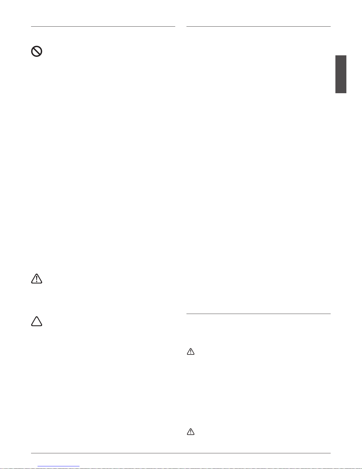
Q Series - Kegeleis
Eisproduktion (10°C / 10°C)
Eisproduktion (21°C / 15°C)
Abmessungen
Externe Breite
Externe Höhe mit Füße(ohne Füße)
Tiefe
Vorratsbehälter
Netto Gewicht / Brutto
W Anschlusswert
Eiswürfel Programm
Kältemittel
Q 25
MODELL
25 kg
20 kg
400 mm
(690) mm
545 mm
10 kg
33 kg / 39 kg
265 W
15
051 Q54 Q Q 75
R134a
500 mm
(693) mm
600 mm
16 kg
45 kg
38 kg
35
41 kg / 48 kg
370 W
R134a
700 mm
585 mm
36 kg
956 mm
75 kg
66 kg
60
55 kg / 63 kg
R134a
620 W
920 mm
650 mm
67 kg
1279 mm
150 kg
135 kg
100 kg / 116 kg
R134a
990 W
90
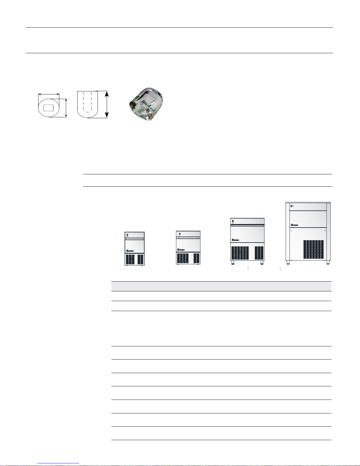
40 mm
26 mm
30 mm
17 g
Page 5

Page 6

Page 7
English
7
71503928/0 - REV.0001/2013
INDICE
1. INSTALLATION . . . . . . . . . . . . . . . . . . . . . . . . . . . . . . . . . . . . . . . . . . 8
1.1
CONNECTING THE APPLIANCE TO THE MAINS
. . . . . . . 8
2
. ACTIVATING THE MACHINE . . . . . . . . . . . . . . . . . . . . . . . . . . . . 9
3. OPERATION . . . . . . . . . . . . . . . . . . . . . . . . . . . . . . . . . . . . . . . . . . . . . 9
3.1 ALARM SIGNALS FOR AIR / WATER MODELS . . . . . . 9
4. CONTROL PANEL SIGNALS . . . . . . . . . . . . . . . . . . . . . . . . . . . 10
5. OPERATING PROBLEMS . . . . . . . . . . . . . . . . . . . . . . . . . . . . . . . 10
6. SERVICE INFORMATION . . . . . . . . . . . . . . . . . . . . . . . . . . . . . . . 10
7. CLEANING AND MAINTENANCE
7.1 CLEANING THE AIR CONDENSER . . . . . . . . . . . . . . . . . 11
7.2 CLEANING THE WATER INLET FILTER . . . . . . . . . . . . . . 11
7.3 CLEANING THE CONTAINER . . . . . . . . . . . . . . . . . . . . . . 11
8. TECHNICAL SERVICE DATA
8.1 ELECTRONIC BOARD FUNCTIONS . . . . . . . . . . . . . . . . 12
8.2 ELECTRONIC BOARD INPUTS AND OUTPUTS . . . . . 12
8.3 OPERATION CHARACTERISTICS . . . . . . . . . . . . . . . . . . . . 12
8.4 FEATURES OF THE GAS REFRIGERATOR
PLANT FREON R404a . . . . . . . . . . . . . . . . . . . . . . . . . . . . . . 13
8.5 PROGRAMMED MAINTENANCE WARNING . . . . . . . . . 13
8.6 CONNECTION OF ELECTRICAL CABLES AND
COMPONENTS TO THE PC BOARD . . . . . . . . . . . . . . . . . 14
9. MAINTENANCE
9.1 PERIODICAL MAINTENANCE AND CLEANING . . . . .15
9.2 ICEMAKER CLEANING . . . . . . . . . . . . . . . . . . . . . . . . . . . . .15
9.3 PARTS REPLACEMENT PROCEDURES . . . . . . . . . . . . . .15
10. WEE . . . . . . . . . . . . . . . . . . . . . . . . . . . . . . . . . . . . . . . . . . . . . . . . . . . 47
11. WIRING DIAGRAM . . . . . . . . . . . . . . . . . . . . . . . . . . . . . . . . . . . . . 48
Description Pag.
WARNING
THE FOLLOWING OPERATIONS AND THOSE
HIGHLIGHTED BY THE SYMBOL AT THE SIDE
ARE STRICTLY FORBIDDEN FOR WHOEVER USES
T
HE MACHINE SUCH OPERATIONS MUST BE
PERFORMED EXCLUSIVELY BY QUALIFIED PERSONNEL
E
specially:
• electrical connections
• water connections
• machine installation
• machine testing
• repairing machine components and parts
• disassembling the machine and/or its
components
• adjustments and settings
• machine cleaning and maintenance relative to
the following parts and components:
- electrical
- electronic
- mechanical
- cooling
THE TEXT WITH THIS SYMBOL
IS OF MORE IMPORTANTE
OR POTENTIAL DANGER SIGNALS
NOTE claries the ongoing operations
i
GENERAL INFORMATION
• The ice making machines approved by VDE bear the symbol
shown in fig. fon the packing, the serial number plate and
the machine structure.
CE
Our products comply with directives 2006/95/ec
2004/108/ec therefore they also bear the marking on the manual cover.
• This appliance is not intended to be used by persons - including children - with reduced physical, sensory or mental
capabilities, or with no experience and knowledge, unless
they have been instructed on how to use the appliance and
are supervised by a person who is responsible for their safety.
Children should be supervised to ensure that they do not
play with the appliance
Do not start the appliance before the technician intervenes
(fig.
r
).
Page 8

English
8
71503928/0 - REV.00 01/2013
1. INSTALLATION
Implement the following operations before activating the
i
ce maker:
1. Verify that the ice maker has not been damaged during
transport (fig.
q
).
2. Remove all the material provided from the container: supply
p
ipe, drain pipe, documentation and any accessories.
3. Clean inside the container with a sponge dampened with
warm water and a little sodium bicarbonate; rinse with clean
water and dry carefully.
4. Place the ice maker in its definite location and ensure that it
is perfectly level (fig.
a
).
Note: When choosing where to install the appliance, make sure
that:
• the room temperature never drops below 10°C (50°F) and does
not exceed 43°C (110° F).
• the water temperature must be no less than 10°C (50°F) and no
more than 32°C (90°F) (fig. u).
• the supply water pressure must be no less than 0,1 MPa (1 bar)
and no more than 0,5 MPa (5 bar).
Should the pressure exceed 0,5 MPa, install a pressure reducer on
the machine water supply (fig. i).
• d) the machine is away from heat sources and in a well-ventilated area (fig. o).
Connect only to the drinking water mains
5. Use the new set of mobile junctions (water pipe) supplied
with the appliance. The old set of junctions must not be
reused.
6. Install the water connections before the electrical connections.
7. Connect the 3/4’’ supply pipe (supplied) to the machine and
to the cold drinking water supply line.
For practical and safety purposes, it is advisable to install a
shut-off valve (not supplied by us) (fig. h: 1. switch; 2. socket;
3. electrical plug; 4. water supply; 5. valve; 6. water drain from
the condenser: water-cooled version; 7. water drain from the
container; 8. water drain with open siphon).
8. Apply the flexible pipe (supplied) with a 20 mm inner diameter and of adequate length (not more than 1 metre from
the machine) to the water drain fitting of the machine in
order to reach the drain well (fig. h).
Note: Install the machine in a position that the ventilation of the
c
ooling unit is not obstructed in any way (only for air-cooled ma-
chines) (fig.
s
).
• Do not install the machine in a dusty room as the condenser of
the cooling unit can be easily clogged (only for air-cooled machines) (fig. 2)).
•
If the machine is installed in an area where the drinking water
has a high content of salt solutions, follow the manufacturer's
instructions in order to minimise the problem.
• To prevent the ice from absorbing bad smells and tastes, never
store food, bottles, etc. in the container.
• Do not leave the ice container door open during normal operation.
There must be a differential switch (cut-out) in the electrical system.
1.1. CONNECTING THE APPLIANCE TO THE MAINS
• If the power supply cable is damaged, it must be replaced
by qualified personnel to prevent any hazards to persons
i
i
Page 9

English
9
71503928/0 - REV.0001/2013
2. ACTIVATING THE MACHINE 3. OPERATION
Implement the following operations before activating the
ice maker.
1
. look at the pictures:
• remove the cover by loosening the relative fastening screws.
• release the gear motor, the blades and the float (where applicable) by removing the factory-set stops 1, 2 and 3, which
have been fixed to prevent damage during transport (fig.
j
)
. For the water-cooled models connect also the second
fitting to the water outlet, which conveys the water coming
from the condenser.
Note: Implement a minimum inclination of 3% to the pipes for
perfect water flow from the appliance, ensuring that these have
no narrowing sections and are not siphoned. It is advisable that
the pipes drain into an open siphon (fig.
h
).
2. Connect the machine to the power supply after having verified that the mains voltage corresponds to that on the serial
number plate on the rear panel of the appliance.
The maximum voltage variation tolerance allowed is ±
10% of the rated value.
• Provide a power supply circuit to the machine, with its own
bipolar main switch and a minimum of 3 mm contact opening. The machine should also have its own fuse or automatic
protection and an earthed plug.
• All must be sized according to the amperage indicated on
the serial number plate (fig. ;). The socket must be easily
accessible.
Simply press the ON/OFF button to start and stop the
machine.
• The ice cube makers can be easily adapted to the furnishing
of every room.
• The ice cubes are formed around the fingers of the evaporator, inside a tray filled with water and continuously moved
b
y revolving blades.
• The level of the water in the tray is kept constant by a float
connected to a microswitch that controls the opening and
closing of a water inlet electrovalve of the water supply.
• When the ice cubes reach the required dimensions, they
come in contact with the revolving blades that cause the relative gear motor to swing, which stresses a micro switch and
simultaneously causes the following through a relay:
- the delivery of hot gas to the evaporator by an electrovalve
opening, which leads to the cubes gradually dropping off
the fingers of the evaporator.
- the tilting of the water tray connected by means of a lever
to a gear motor.
• The cubes drop and slide on a slanting grid inside the tray
and are conveyed into the container beneath.
• The remaining water in the tray is collected into the relative
pan on one side of the container and conveyed towards the
drain. The tray automatically returns to its horizontal position
after about a minute and fills with water till the pre-set level.
In the meantime, the hot gas valve closes and the ice forming cycle proceeds smoothly; a complete cycle can vary from
about 15’ to about 25’ depending on the water and room
temperatures.
• The quantity of ice inside the container is controlled by the
electronic sensor fixed on one side of the container itself;
when the ice cubes reach the level of the bulb, the machine
stops completely. After removing enough ice from the container for no cubes to be in contact with the bulb, the appliance will resume its normal production.
Note: After removing the ice cubes, remove any remaining ice
on the control bulb for production to resume quicker.
3.1 ALARM SIGNALS FOR AIR / WATER MODELS
• Overheating condenser: the machine restarts automatically
once the alarm has been resolved. The cause may be due to:
clogged air filter, faulty fan, room temperature too high, no
water (only in the water version).
• Water error: if there is no water, the machine restarts automatically 60 minutes after the alarm is triggered.
Note: You can exit from the alarm status after having disconnected / connected the power supply (ON/OFF button).
• The machine stops when the container is full: the sensor
of the container is controlled by the control board and stops
the machine when the ice comes in contact with it. The machine stops at the end of the defrosting cycle.
iii
Page 10

English
10
71503928/0 - REV.00 01/2013
6. SERVICE INFORMATION
LL= flashing slowly
LV= flashing quickly
LA= alternate flashing
ON = steady light
1. Verify that the water supply valve is open, then plug in the
m
achine and switch on the main switch; the appliance starts-
up in automatic mode (fig.
g
) after having pressed the
ON/OFF start button (fig. 2@).
2. Verify that the water reaches the tray, the float stops the
water before the overflow and that there are no leaks in the
system and in the water channels. The normal level of water
inside the tray is about 5/10 mm from the upper edge (fig.
k
).
The level of water can be adjusted by rotating the microfloat
or the water sensor on the slot on the relative support after
having loosened fastening screw 1 (fig. k). This adjustment
must be implemented after having disconnected the power
supply.
3. Verify that there is no abnormal vibration due to loose screws.
4.
Always stop the appliance before implementing any operations
to resolve water leaks, tighten screws, etc.
5. Verify an ice production cycle ensuring that the cubes are
conveyed into the container.
6. Verify that the container sensor functions properly: place an
ice cube on the bulb inside the container; the appliance
should stop within 1 minute and restart automatically shortly
after removing it.
7. Replace the cover previously removed.
THE FOLLOWING OPERATIONS MUST BE
IMPLEMENTED SOLELY BY OUR
QUALIFIED PERSONNEL
4. SIGNALS
5.
OPERATING PROBLEMS
• If the condenser overheats
The machine stops and only the air/water condensation remains in operation. The machine automatically restarts when the temperature returns to below the limits set. Only after three consecutive alarms within a period of 5 hours, the machine turns off and
stays off.
• Freezing cycle too long
In the case of three consecutive alarms within 5 hours, the machine stops.
Calculation of the maximum time of the freezing cycle:
1stcycle = 50'
2ndcycle = duration of 1 cycle x 1.5.
If the 1st cycle lasted less than 7' the maximum time of the next cycle will be 50'.
• Defrosting too long
If the defrosting time is greater than 2 minutes and there are 2 consecutive failures within 5 hours, the machine stops.
• Freezing cycle less than 7 minutes
The electronics calculate the cycle time as too long at 50 minutes.
• Water loading too long
If the load time for the water is greater than 5' the machine stops in alarm. After a break of 120' the machine restarts automatically.
If water shortage is ongoing, the machine will attempt to restart every 120'.
Function Status
Led 1
G
reen
Led 2
R
ed
Notes
Machine ON ON OFF
A
pplicable to all
conditions that are
n
ot in alarm/error
Bin temperature
sensor error
OFF LL
Temperature sensor
out of range.
Machine OFF
Condenser
t
emperature
sensor error
O
FF
L
L
Temperature sensor
out of range.
The machine
continuous to run
Error cold cycle too
long or defrosting
too long
ON ON Machine OFF
Condenser
overheating error
OFF ON Machine OFF
No water error LL ON
The signal is triggered
after attempting to restart
Maintenance
warning
LA LA
The pre-set number of
operating hours has been
reached. The machines
continous to run
Wash / clean LV LV
Signalled during the wash
routine
Start stand-by LV OFF
Waits to start after
switch-o
Page 11

English
11
71503928/0 - REV.0001/2013
7. CLEANING AND MAINTENANCE
• Use a cloth dampened with a specific chlorine-free product
for stainless steel to clean the structure.
Note: Disconnect the electrical power supply from the appliance
to perform maintenance and cleaning operations.
7.1 CLEANING THE AIR CONDENSER
• To make the most of your appliance in terms of efficiency
and durability, the air filter at the front of the machine must
be cleaned every week (fig. 2#).
• The filter is removed by simply extracting it. Simply wash the
filter with a water jet of warm water and dry it before setting
it back in place.
Do not use brushes or blunt objects to clean the filter.
It is absolutely forbidden to operate the producer without
the air filter to prevent malfunctioning.
7.2 CLEANING THE WATER INLET FILTER
• Close the water shut-off valve of the appliance, disconnect
the water inlet pipe and remove the filter screen that is on
the water inlet electrovalve with a pair of pliers.
• Clean the screen with a water jet and reassemble it into its
place.
7.3 CLEANING THE CONTAINER
• Remove the ice from the container. Clean inside the container with a sponge dampened with warm water and a little sodium bicarbonate;
• rinse with clean water and dry carefully.
For all extraordinary maintenance and/or repairs (mec
hanical, cooling and electrical parts) that require adjustments and/or components to be replaced, always refer to
an authorised service centre.
If the appliance should not be used for long periods of
t
ime:
- disable the machine
- remove all the ice from the container
- drain all the water
- thoroughly clean the machine
- leave the door of the container ajar
i
THE FOLLOWING OPERATIONS MUST BE
IMPLEMENTED SOLELY BY OUR
QUALIFIED PERSONNEL
Page 12

English
12
71503928/0 - REV.00 01/2013
8. TECHNICAL SERVICE DATA
8.1 ELECTRONIC BOARD FUNCTIONS
•
Ice level check with probe
• Condensing temperature check with probe (machine stop
with temperature > 70°C water version; > of 80°C air).
• Maintenance check. The maintenance alert can be programmed after a certain number of hours of functioning.
8.2 ELECTRONIC BOARD INPUTS AND OUTPUTS
• Condenser probe: with condenser temperature < 24°C, the
board makes the fan turn guaranteeing optimal condition of
condensation and machine yield.
• Resistance values of the temperature probes (deposit probe
and condenser probe) with reference to the room temperature:
•
PCB MICROPROCESSOR RESET
Pressing the ON/OFF button.
8.3 OPERATION CHARACTERISTICS
• On the starting the machine goes into defrosting and disc
harge the water pan.
• The production cycle start with two minutes of delay that
allow a correct balancing of the refrigeration system and
therefore a good output and a best production.
• During the machine operation, at the end of every defrosti
ng, the water load happens with 80 seconds of delay, this to
allow the evaporator subcooling.
• When the bin is full of ice, the probe comes in contact with
the ice and the electronic card stop the machine only on the
end of defrosting time. This to always have the cubes completely formed and at the same dimensions.
• Signalling of alarms for the models air and water version:
- condenser overheating : the machine goes to alarm and it
restart again automatically once that the cause has been removed and / or the temperature has re-entered in the range
of established operation;
- error of not water feeding: in case of lack of water the machine automatically start again after 60 minutes from the
alarm reset.
THE FOLLOWING OPERATIONS MUST BE
IMPLEMENTED SOLELY BY OUR
QUALIFIED PERSONNEL
Temperature °C Sensor resistance Ohm
20 2762,034556
25 2200,000000
30 1765,531939
Low voltage
inputs
Condenser probe
Container Probe
Water level sensor
Defrosting start micro
Defrosting end micro
High voltage
inputs 230V/50HZ
Compressor
Tilting Motor
Hot gas electrovalve
Water electrovalve
Blades gear motor
Electric fan
Electronic board
Page 13
English
13
71503928/0 - REV.0001/2013
8
.4 FEATURES OF THE GAS REFRIGERATOR PLANT
FREON R134a
• Medium and maximum series “E” blade machines absorption
at room temperature of 32°C.
• Condensing pressure and evaporator temperature cycle start
a
nd end at room temperature of 32°C.
* Expressed in water litres per hour at water temperature of
15°C and room temperature of 21°C
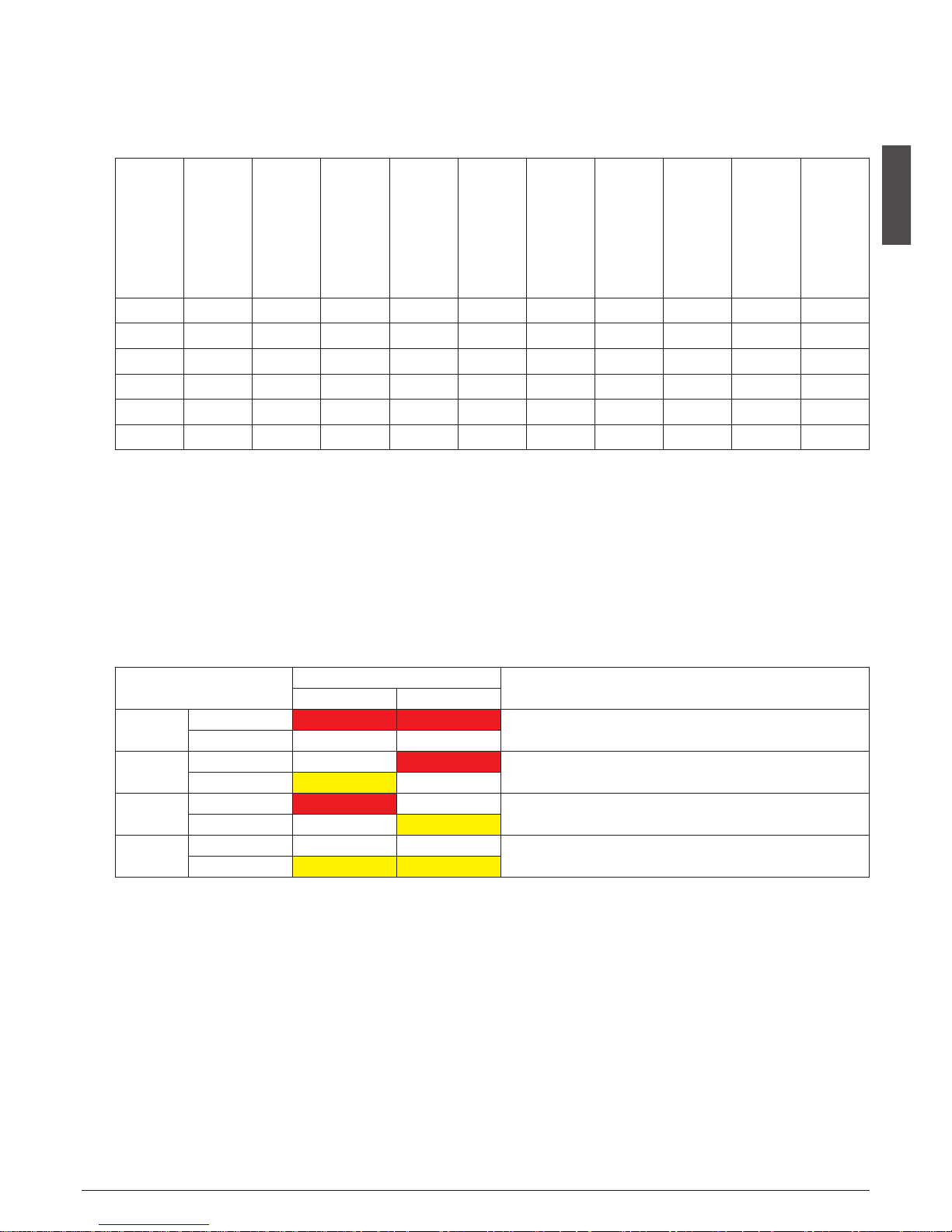
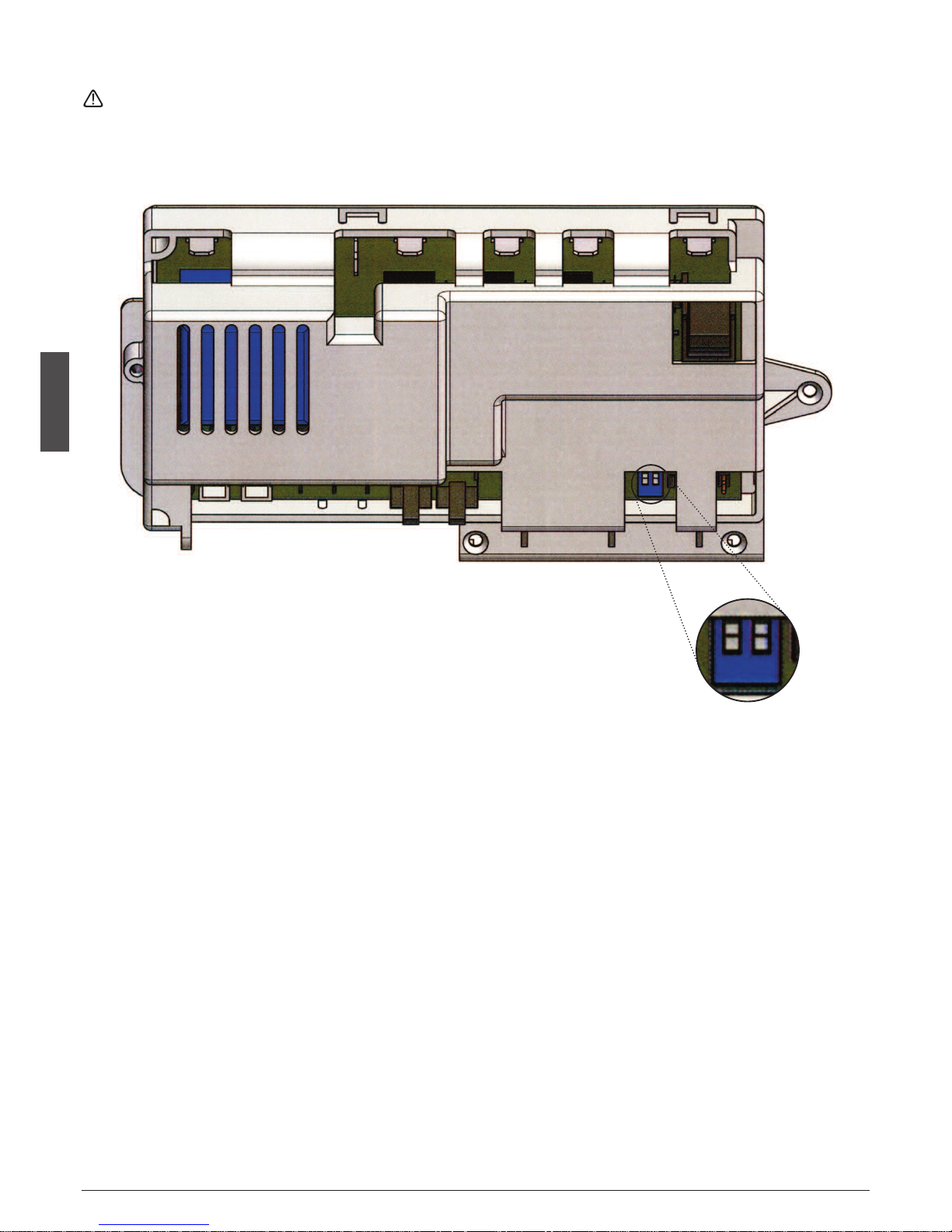
8.5 PROGRAMMED MAINTENANCE WARNING
• The programmed maintenance time is set at 0 hour by the
manufacturer.
• In order to modify this time and/or reset the maintenance
recall function; proceed with dipswitch setup, as shown in
the attached table.
* In case of programmed maintenance, to reset and to restore
the programming to the initial value it's necessary to press
the RESET button for at least 5 seconds.
DIP
NOTE
1 2
1
OFF
Interval of maintenance to 0 hour
ON
2
OFF
Interval of maintenance to 2000 hours
ON
3
OFF
Interval of maintenance to 6000 hours
ON
4
OFF
Interval of maintenance to 3500 hours
ON
Machine
Gas
Max. ampere
Medium ampere
Condensing
pressure strarting
cycle (bar)
Evaporation
temperature
starting cycle (°c)
Condensing
pressure end cycle
(bar)
Evaporation
temperature end
cycle (bar)
Electrical
consumption
on 24 hrs/kw
Cubes for cycles and
weight singel cube
in gr
Water consumption
l/h*
21 134 A 2 A 1,8 A 11,5 -3,3 9 -17 7,5 15/17 GR 6
25 134 A 1,6 A 1,4 A 11 -2 9 -13 5,8 15/17 GR 2,8
35 134 A 2,7 A 2,1 A 14 -2 10 -15 8,6 20/17 GR 4,7
60 R134a 4,2 A 3,4 A 14,7 -2 11,3 -15 12,7 35/17 GR 7,5
75 R134a 4,6 A 3,8 A 14,6 -2 11,4 -13 13,3 60/17 GR 9,4
90 R134a 4,7 A 4,2 A 14,9 -2 10,8 -15 14,4 60/17 GR 12,5
Page 14

English
14
71503928/0 - REV.00 01/2013
8
.6 CONNECTION OF ELECTRICAL CABLES AND COMPONENTS
TO THE PC BOARD
O
bserve the connection with the colors of electric cables.
Float level sensor
Micro tip
Cumun micro
Micro defrost
Probe deposit ice
Condenser probe
Blue
Brown
Orange
Black
White
Red
Dip. Switch
to set the
maintenance hours
Page 15

English
15
71503928/0 - REV.0001/2013
9. MAINTENANCE
9.1 PERIODICAL MAINTENANCE AND CLEANING
C
leaning and maintenance especially will vary, depending
upon ambient and use conditions.
In particular affect: hard water, ice volume produced and
location requirements.
The following maintenance procedures should be schedu
led once per year al least from the local service Agency.
Be sure the electrical power supply of the machine is OFF,
before starting any maintenance and cleaning procedure.
a) Close the water supply, shut-o valve, disconect the water
inlet pipe and remove the strainer from its seat in the water
inlet elettrovalve withdrawing it bay means of pilers. Clean
the strainer under running water and reassemble.
b) Check that the ice maker cabinet is levelled in side-to-side
and front-to-rear directions.
c) Check paddle shaft motor and harvest motor operation.
d) If you think it opportune, check by means of a gauges the
delivery pressure and the evaporator temperature.
e) Clean the air-cooled condenser using a nonmetal brush or a
vacuum cleaner.
f) Check that fan blades move freely and are not touching any
sourfaces.
g) Check for refrigerant leaks.
h) Check for water leaks. Pour water down bin drain to be sure
that drain line is open and clear.
i) Check operation of the bin thermostat.
9.2 ICEMAKER CLEANING
a) Remove the top panel.
b) Remove all ice from the storage bin.
c) Close the water supply shut-o valve.
d) Fill tilting pan with a solution of water and citric acid (200-
400 grs. of citric acid in one litre of water) and by means of
a brush clean the inside of the tilting pan and the evaporator ngers. Start the icemaker to tilt the pan, rinse with clean
water in abudance and repeat cleaning three times.e)
Add hot water to the ice storage bin and thoroughly wash
and rinse all surfaces within the bin.
f) Clean and sanitize the ice storage bin frequently.
9.3 PARTS REPLACEMENT PROCEDURES
a) ADJUSTABLE LEGS FOR N55S÷N90L MODELS
• Using the couplings and adjustable feet supplied and screwing them on the base nipples the icemaker can be placed at
9,5 cm. abt. from ground level.
• Extended feet are available on request to adjust the icemaker at 16 cm. about from ground level.
• The adjustment should be performed during initial installation of the cabinet and any time the cabinet is moved from
the original location to another site.
Be sure the electrical power supply and the water supply
are OFF, before starting any removal and replacement procedures, as a precaution to prevent possible personal injury or damage to equipment.
b) COMPRESSOR REPLACEMENT
• Remove the front panel grid and the right side panels.
•
On N45S÷N140 models remove the rear panel grid and the
side panels.
• Remove the cover and disconnect the electrical leads from
the compressor junction box.
• Bleed o or blow the refrigerant charge through the valve.
•
Unsolder and disconnect both the suction line and the discharge line (from the compressor).
• Remove compressor mounting bolts and the compressor
from the unit base.
• Always install a replacement drier, anytime the sealed refrigeration system is open. Do not replace the drier until all other
repairs or replacements have been completed.
• To install the replacement compressor follow previous steps
in reverse.
• Thoroughly evacuate the system to remove moisture and
non-condensables after compressor replacement.
• Before proceeding with the refrigerant charge check nameplate for specic refrigeration charge for individual cuber.
c) AIR COOLED CONDENSER REPLACEMENT
• Remove the front panel grid and the right side panels.
• Remove the screws which attach the condenser to the unit
base.
• Bleed o or blow the refrigerant from the system.
• Unsolder the refrigerant lines from condenser and remove it
from the unit.
• Install the replacement condenser following previous steps
in reverse.
• Thoroughly evacuate the system to remove moisture and
non condensables; then proceed with the charge of FREON
R134a.
d) DRIER REPLACEMENT
• Remove the front panel grid and the right side panels.
• Bleed o or blow the refrigerant charge through the Henry-
type valve.
• Unsolder the capillary tube from one end of the drier and
the refrigerant line from the other end.
• To install a replacement drier remove factory seals.
• Thoroughly evacuate the refrigerant system.
• Charge the system with refrigerant by weight (see name-
plate) and check for leaks.
e) FAN MOTOR REPLACEMENT
• Remove the front panel grid and the right side panels.
• Trace the electric wire leads of fan motor and disconnect the
same.
• Remove the bolts securing the fan motor assembly to the
cabinet base and the remove the assembly.
• Install the replacement fan motor following previous steps
in reverse anc check that the fan blade do not touch any
sourface and move freely.
Page 16

English
16
71503928/0 - REV.00 01/2013
f
) EVAPORATOR ASSEMBLY REPLACEMENT
• Remove the top cover.
• Remove six screws securing the paddle shaft supports (two)
and the paddle motor support; then remove the paddle
motor/paddle shaft/supports assembly.
•
Remove the bolts securing the evaporator supports (two) to
the cabinet.
• Sideways remove the evaporator supports.
• Unsolder the capillary tube, the hot gas solenoid valve tube
and the suction line.
•
To install the replacement evaporator assembly follow previous steps in reverse.
• Install the replacement drier; thoroughly evacuate the system and proceed with the refrigerant charge.
g) WATER RESERVOIR/TILTING LEVER/SUPPORT ASSEMBLY
REPLACEMENT
• Remove screws and top cover.
• Remove the gear motor/paddle shaft/support assembly.
• Remove the screws securing the evaporator supports (two).
• Sideways remove one evaporator support support as well as
one reservoir gudgeon support.
• Slightly lift the evaporator and remove the water reservoir
assembly.
• To install the replacement water reservoir assembly follow
previous steps in reserve.
h) WATER INLET ELECTROVALVE REPLACEMENT
• Remove the rear panel.
• Check that water supply is closed.
• Disconnect the water supply connection pipe from the valve
and that of the electrovalve from the reservoir.
• Break contact from the electrovalve and remove the screws
(two) securing the electrovalve to the relevant frame.
• To install the replacement electrovalve follow previous steps
in reverse; before installing the water supply pipe check that
the gasket is not defective.
i) PADDLE MOTOR REPLACEMENT
• Remove the top cover.
• Remove six screws securing the paddle shaft supports (two)
and the paddle motor support.
• Trace the electric wire leads of paddle motor and disconnect
the same; then remove the paddle shaft motor assy.
• Remove the paddle shaft assy from the paddle motor gudgeon (or guide pin).
• To install the replacement paddle motor follow previous
steps in reverse.
l
) HARVEST MOTOR REPLACEMENT
• Remove the top cover.
• Remove the screws securing the harvest motor to the cabi-
net base.
• Remove the seeger from the cam pin.
•
Trace the electric wire leads of harvest motor and disconnect
the same; then remove the harvest motor/cam/support assembly.
• Remove the lock pin securing the cam to the motor shaft
and the screws joining the harvest notor to the relative supp
ort.
• Install the replacement harvest motor on the support and
apply the cam; make a Ø 3 mm hole on the motor shaft and
to do it take as a guide the hole already existing on the cam.
• To install the replacement harvest motor assy follow previous steps in reverse.
Page 17

Deutsch
17
71503928/0 - REV.0001/2013
INDEX
1. INSTALLIEREN . . . . . . . . . . . . . . . . . . . . . . . . . . . . . . . . . . . . . . . . 18
1.1 ANSCHLUSS DES GERÄTES
AN DIE STROMVERSORGUNG . . . . . . . . . . . . . . . . . . . . 18
2. INBETRIEBNAHME . . . . . . . . . . . . . . . . . . . . . . . . . . . . . . . . . . . . 19
3. ARBEITSWEISE . . . . . . . . . . . . . . . . . . . . . . . . . . . . . . . . . . . . . . . . 19
3.1 ALARMMELDUNGEN FÜR DIE MODELLE
AUSFÜHRUNG WASSER / LUFT . . . . . . . . . . . . . . . . . . .19
4. MELDUNGEN AUF DER SCHALTFLÄCHE . . . . . . . . . . . . . 20
5. FUNKTIONSSTÖRUNGEN . . . . . . . . . . . . . . . . . . . . . . . . . . . . 20
6. HINWEISE FÜR DEN “SERVICE” . . . . . . . . . . . . . . . . . . . . . . . 20
7. REINIGUNG UND WARTUNG
7.1 KONDENSATOR REINIGEN . . . . . . . . . . . . . . . . . . . . . . . . 21
7.2 REINIGEN DES ZUFLUSSWASSERFILTERS . . . . . . . . . 21
7.3 REINIGEN DES VORRATSBEHÄLTERS . . . . . . . . . . . . . . 21
8. TECHNISCHE DATEN FÜR DEN SERVICE
8.1 FUNKTIONEN DER ELEKTRONISCHEN
LEITERPLATTE . . . . . . . . . . . . . . . . . . . . . . . . . . . . . . . . . . . . 22
8.2 EINGÄNGE UND AUSGÄNGE
DER ELEKTRONISCHEN LEITERPLATTE . . . . . . . . . . . . 22
8.3 BETRIEBSEIGENSCHAFTEN . . . . . . . . . . . . . . . . . . . . . . . 22
8.4 EIGENSCHAFTEN DER KÜHLANLAGE . . . . . . . . . . . . 23
8.5 PROGRAMMIERTER WARTUNGSHINWEIS . . . . . . . . . 23
8.6 ZUSAMMENSTECKEN DER ELEKTRISCHEN
LEITUNGEN UND KOMP. FÜR DIE PC BOARD . . . . . 24
9. WARTUNG
9.1 WARTUNG UND REGELMÄSSIGE REINIGUNG . . . . .25
9.2 REINIGEN DER EISMASCHINE . . . . . . . . . . . . . . . . . . . . .25
9.3 VORGANGSWEISE ZUM AUSTAUSCHEN
VON TEILEN . . . . . . . . . . . . . . . . . . . . . . . . . . . . . . . . . . . . . . .25
10. RAEE . . . . . . . . . . . . . . . . . . . . . . . . . . . . . . . . . . . . . . . . . . . . . . . . . . 47
11. SCHALTPLÄNE . . . . . . . . . . . . . . . . . . . . . . . . . . . . . . . . . . . . . . . . 88
Beschreibung Pag.
ACHTUNG
DIE MIT DIESEM SYMBOL GEKENNZEICHNETEN
OPERATIONEN DÜRFEN NUR VON EINEM
AUTORISIERTEN KUNDENDIENSTTECHNIKER
DURCHGEFÜHRT WERDEN.
Im Einzelnen:
• Elektrischer Anschluss
• Wasseranschluss
• Installation
• Maschinentest
• Reparatur aller Teile und Werkteile des
Gerätes
• Demontage des Gerätes bzw. seiner Bauteile
• Regulierung und Eichung des Gerätes
• Wartung und Reinigung des Gerätes
Entsprechend Ihrer Teile und Komponenten:
- Elektrische,
- Elektronische,
- Mechanische,
- Gefrier-.
DER TEXT MIT DIESEM SYMBOL IST VON
BESONDERER BEDEUTUNG UND WEIST AUF
POTENZIELLE GEFAHR HIN
WICHTIG klärt den laufenden Betrieb
i
ALLGEMEINE INFORMATIONEN
• Die Eismaschinen sind durch VDE zugelassen und tragen das
in Abb. fdargestellte Symbole auf der Verpackung, auf
dem Typenschild und auf der Karosserie.
CE
unsere produkte entsprechen den bestimmungen
2006/95/ce - 2004/108/ce und tragen daher das zeichen
auf dem umschlag der bedienungsanleitung.
• Dieses Gerät ist nicht dafür bestimmt, von Personen (einschließlich Kindern) benutzt zu werden, die aufgrund ihrer
physischen, sensorischen oder geistigen Fähigkeiten oder
ihrer Unerfahrenheit und Unkenntnis nicht in der Lage sind,
das Gerät sicher zu bedienen, es sei denn sie werden durch
eine für ihre Sicherheit zuständige Person beaufsichtigt und
erhielten von ihr Anweisungen, wie das Gerät zu benutzen
ist. Kinder sollten beaufsichtigt werden, um sicherzustellen,
dass sie nicht mit dem Gerät spielen.
Das Gerät nicht vor dem Eingriff des technischen Personals
in Betrieb nehmen (Abb. r)
Page 18

Deutsch
18
71503928/0 - REV.00 01/2013
1. INSTALLIEREN
Vor der Inbetriebnahme folgende Hinweise für die Aufstell
ung des Gerätes beachten:
1. Gerät auf Transportschäden untersuchen (Abb.
q
).
2. Zubehör aus dem Vorratsbehälter entnehmen: Versorgungsund Abflussschläuche, Unterlagen und eventuelles Zubehör.
3
. Vorratsbehälter mit einem Schwamm, warmem Wasser und
einem Sodabikarbonat auswaschen. Mit klarem Wasser nachspülen und gut austrocknen.
4. Gerät an dem vorgesehenen Platz aufstellen und waagerecht
ausrichten (Abb.
a
).
Wichtig: Bei der Auswahl des Installationsraums des Gerätes
muss sichergestellt werden, dass:
• die Raumtemperatur sinkt nicht unter 10°C (50°F) und steigt
nicht über 32°C (90°F).
• die Wassertemperatur sollte nicht unter 10°C (50°F) und nicht
über 32°C (90°F) sein (Abb. u).
• der Wasserversorgungsdruck darf nicht unter 0,1 MPa (1 bar)
liegen und 0,5 MPa (5 bar) nicht überschreiten.
Sollte der Druck 0,5 MPa überschreiten muss ein Druckminderer
an die hydraulische Versorgung der Maschine angebracht werden (Abb. i).
• in der Nähe der Maschine dürfen keine Wärmequellen vorhanden und Luftzirkulation muss gegeben sein (Abb. o).
Anschluss nur an das Trinkwassernetz
4. Benutzen Sie den neuen Bausatz der mobilen Verbindungen
(Wasserleitung), der mit dem Gerät mitgeliefert wird. Der alte
Bausatz darf nicht wiederverwendet werden.
4. Die hydraulischen Anschlüsse vor den elektrischen ausführen.
4. Den beiliegenden Anschlussschlauch 3/4” am Gerät und am
Trinkwasseranschluss anschließen.
Aus praktischer Sicht und für die Sicherheit empfiehlt es sich,
ein Absperrventil vorzusehen (gehört nicht zum Lieferumfang) (Abb. h: 1. Schalter; 2. Steckdose; 3. Stecker; 4. Wassereinlass; 5. Absperrventil; 6. Wasserabfluss vom
Kondensator: wasserkühlende Ausführung; 7. Wasserabfluss
vom Behälter; 8. offener Wasserabfluss).
4. Abflussstutzen über einen Plastikschlauch (nicht länger als 1
Meter von der Maschine entfernt) von 20 mm lichtem Durchmesser zu einem Ablauf (Abb. h) führen.
Wichtig: Die Maschine an einem Ort aufstellen, wo die Ventilat
ion der Kühleinheit nicht verdeckt wird (nur für luftgekühlte Ma-
schinen) (Abb.
s
).
• Die Maschine nicht an staubigen Orten aufstellen, da sich hier
der Kondensator der Kühleinheit schnell verstopfen kann (nur bei
luftgekühlten Maschinen ) (Abb. 2))
•
Sollte die Maschine an einem Ort aufgestellt sein, wo das Trinkwasser einen hohen Salzgehalt hat, sollten die Anweisungen der
Herstellerfirma abgewartet werden, damit Störungen minimal
gehalten werden können.
• In dem Nahrungsmittelbehälter keine Flaschen oder ähnliches
aufbewahren, damit das Eis keinen schlechten Geruch oder Geschmack annehmen kann.
• Während des normalen Betriebes die Klappe des Eisbehälters
nicht offen stehen lassen
Die elektrische Anlage muss mit einem Differenzialschalter
ausgestattet sein (Sicherung).
1.1 ANSCHLUSS DES GERÄTES AN DIE STROMVERSORGUNG
• Bei einer eventuellen Beschädigung des elektrischen Stromkabels muss es durch Fachpersonal ersetzt werden, um jegliche Gefahr für Personen auszuschließen.
i
i
Page 19

Deutsch
19
71503928/0 - REV.0001/2013
2. INBETRIEBNAHME 3. ARBEITSWEISE
Vor der Inbetriebnahme folgende Hinweise für die Aufstellung des Gerätes beachten:
1
. Zeichnungen nachschauen.
• Deckel nach Lösen der beiden Schrauben abnehmen.
• Transportblockierungen 1, 2, 3, von Paddelmotor, Paddeln
und Schwimmer entfernen (Abb.
j
) Bei Ausführungen mit
Wasserkühlung muss an den Abfluss auch einen zweiten Ans
chluss haben, der das Wasser aus dem Kondensator ableitet
Wichtig: Für einen richtigen Wasserabfluss muss eine Neigung
der Leitungen von min. 3% vorgesehen werden, wobei darauf geachtet werden muss, dass diese keine Knicke oder Verschlüsse
aufweisen. Es ist angemessen, dass die Leitungen durch einen offenen Siphon ableiten (Abb.
h
).
2. Vor dem Netzanschluss der Maschine ist zu überprüfen, dass
die vorhandene Spannung mit den Angaben des Typenschildes auf der Rückseite des Gerätes übereinstimmt.
Die maximale zugelassene Toleranz der Spannungsabweichung beträgt ± 10% vom Nennwert.
• Für das Gerät muss ein elektrischer Versorgungskreislauf mit
einem doppelpoligen Hauptschalter, einer Unterbrechung
der Kontakte von min. 3mm sowie einer Sicherung oder automatischen Schutz und einer geerdeten Steckdose vorhanden sein.
• Alles muss für die Stromstärke geeignet sein, die auf dem
Schild der Fabrikationsnummer verzeichnet ist (Abb. ;). Die
Steckdose sollte einfach zu erreichen sein.
Zum Ein- und Ausschalten der Maschine ist lediglich der
ON/OFF-Schalter zu drücken .
•
Die Eiswürfelerbereiter sind besonders kompakt. Sie lassen sich
daher leicht in jede Einrichtung einfügen.
• Die Eiswürfel entstehen an den Fingern eines Verdampfer, die
in eine mit Wasser gefüllte Wanne hineinragen, welches durch
drehende Paddel ständig in Bewegung gehalten wird.
•
Der Wasserstand wird durch einen Schwimmer konstant gehalten,
der über einen Mikroschalter das Wasser-Magnetventil steuert.
• Wenn die Eiswürfel die vorgesehene Größe erreicht haben und
die Paddel berühren, bewegt sich der Paddelmotor und schaltet über einen Mikroschalter das Relais ein.Dadurch geschieht
Folgendes:
- heißes Gas strömt durch das geöffnete Magnetventil in den
Verdampfer. Er wird erwärmt und die Eiswürfel lösen sich.
- der Wannenmotor läuft an und schwenkt die Wanne abwärts.
• Die Eiswürfel werden durch das Ablenkgitter in den Vorratsbehälter gelenkt.
• Das in der Wanne verbliebene Wasser gelangt in den Wasserbehälter an der Seite des Vorratsbehälters und von dort in den
Abfluss. Die Wanne bewegt sich nun automatisch nach etwa
einer Minute in die Horizontale zurück und füllt sich bis zu dem
eingestellten Wasserhöchststand. Inzwischen ist das Heißgasventil geschlossen und der neue Gefriervorgang beginnt.Die
Zeit für einen kompletten Programmablauf liegt zwischen 15’
und 25’ Minuten in Abhängigkeit von der Wasser- und der Umgebungstemperatur.
• Die Füllung des Vorratsbehälters wird durch einen Thermostatfühler überwacht, der an einer Seitenwand angebracht ist. Sobald der Fühler von Eis berührt wird, wird die Eisproduktion
unterbrochen. Erst wenn soviel Eis entnommen wurde, dass der
Fühler wieder frei ist, arbeitet das Gerät automatisch weiter.
Wichtig: Für eine schnelle Wiederaufnahme der Produktion, nach
der Entnahme den Kontrollfühler von eventuellen Eisrückständen
befreien.
3.1 ALARMMELDUNGEN FÜR DIE MODELLE AUSFÜHRUNG
WASSER / LUFT
• Temperaturüberschreitung Kondensator: das Gerät schaltet
sich automatisch wieder ein sobald der Grund der Alarmmeldung beseitigt wurde. Auslöser können sein: Luftfilter verstopft,
Ventilator defekt, Raumtemperatur zu hoch, Wasser fehlt (nur
bei der Ausführung mit Wasser).
• Fehler Wasser: sollte Leitungswasser fehlen, schaltet sich das
Gerät 60min nach der Alarmmeldung automatisch wieder ein.
Wichtig: Es ist möglich die Alarmbedingungen abzuwenden ohne
die Stromversorgen ab- und wieder einzuschalten (Taste ON/OFF).
•
Ausschalten des Gerätes aufgrund eines vollen Behälters. Die
Sonde des Behälters steuert von der elektronischen Leiterplatte aus
die Abschaltung des Gerätes, sobald Eis mit ihr in Berührung kommt.
Das Gerät schaltet sich am Ende des Entfrostungszyklus ab.
iii
Page 20

Deutsch
20
71503928/0 - REV.00 01/2013
6. HINWEISE “SERVICE”
LL= langsames Aufleuchten
LV= schnelles Aufleuchten
LA= unterschiedliches Aufleuchten
ON= Dauerlicht
1. Wasserabsperrventil öffnen und Netzstecker einstecken. Das
G
erät nimmt automatisch seinen Betrieb auf (Abb.
g
)
, nach-
dem die Betriebstaste ON/OFF gedrückt wurde (Abb.
2@
).
2. Sicherstellen, dass das Wasser an der Wanne angelangt, dass
der Sensor bzw. der Schwimmer den Eintritt vor dem Überlaufen stoppt und das keine Leckagen an der Anlage und an
den Wasserleitungen vorliegen. Das normale Wasserniveau
in der Wanne beträgt circa 5 / 10 mm an den oberen Rändern (Abb. k)
Der Wasserstand kann nach dem Lösen der Schrauben 1
(Abb. k) durch Schwenken des Schwimmschalters verändert werden. Diese Einstellung nur mit abgeschalteter Stromzufuhr vornehmen.
3. Prüfen, ob Nebengeräusche auftreten. Diese werden meist
durch gelockerte Schrauben verursacht.
4. Keine Arbeiten am Gerät durchführen während dieses unter
Spannung steht.
5. Arbeitsablauf des Gerätes kontrollieren. Prüfen, ob alle Eiswürfel in den Vorratsbehälter gelangen.
6. Die Funktion der Sonde im Behälter prüfen: einen Eiswürfel
an das Thermostat im Inneren des Behälters halten. Das Gerät
sollte sich innerhalb von 1min abschalten und automatisch
wieder einschalten, nachdem das Eis entfernt wurde, nach
nicht mehr als einer weiteren Minute.
7. Deckel wieder aufsetzen.
DIE FOLGENDEN EINGRIFFE DÜRFEN NUR
VON EINEM AUTORISIERTEN KUNDEN
DIENSTTECHNIKER DURCHGEFÜHRT WERDEN
4. MELDUNGEN
5. FUNKTIONSSTÖRUNGEN
• Im Falle einer erhöhten Kondensatortemperatur
Die Maschine stoppt, nur der Luft-Wasserkondensator bleibt in Betrieb. Die Maschine startet automatisch erneut, wenn die Temperatur wieder unter den gesetzten Grenzwert fällt. Erfolgt innerhalb von 5 Stunden der dritte Alarm in Folge, dann stoppt die Maschine
komplett.
• Einfrier-Zyklus zu lang
Wenn der dritte Alarm in Folge innerhalb von 5 Stunden erfolgt, stoppt die Maschine komplett.
Berechnung der maximalen Zeit des Einfrier-Zyklus:
1. Zyklus = 50 Minuten
2. Zyklus = Dauer des 1. Zyklus x 1,5.
Wenn der 1. Zyklus weniger als 7 Minuten dauerte, dann liegt die maximale Zeit des folgenden Zyklus bei 50 Minuten.
• Abtau-Zyklus zu lang
Wenn das Abtauen länger als 2 Minuten dauert und innerhalb von 5 Stunden 2 Fehler auftreten, dann stoppt die Maschine.
• Einfrier-Zyklus liegt unter 7 Minuten
Die Elektronik berechnet die Zykluszeit auf 50 Minuten oder länger.
• Wasserbeladezeit zu lang
Wenn die Wasserbeladezeit 5 Minuten übersteigt, dann erfolgt ein Not-Stopp der Maschine. Nach einer Zeit von 120 Minuten startet
die Maschine automatisch erneut. Wenn das Wasser weiterhin fehlt, dann versucht die Maschine alle 120 Minuten neu zu starten.
Statusfunktion
LED 1
Grün
LED 2
Rot
Anmerkungen
Gerät eingeschaltet ON OFF
Gilt für alle Zustände, die
nicht Alarme oder Fehlermeldungen sind
Fühler Vorratsbehälter defekt
OFF LL
Fühler außerhalb des
Richtwertes
Kondensatorsfühler
defekt
OFF LL
F
ühler außerhalb des
Richtwertes Die Maschine
f
unktioniert auf jeden Fall
Fehler: Kühlzyklus zu
lang oder Abtauvorgang zu lang
ON ON Maschine zu
Fehler
Temperaturüberschreitung
Kondensator
OFF ON Maschine zu
Fehler kein Wasser LL ON
Die Meldung wird angezeigt nach Versuch Gerät
wieder einschalten
Wartungsanzeige LA LA
Betriebstundenlimit erreicht
Die Maschine funktioniert
auf jeden Fall
Waschen / Reinigung
LV LV
Es wird angezeigt wenn
das Gerät sich in Routinereinigung bendet
Warten Start LV OFF
Warten auf Neustart nach
dem Ausschalten
Page 21

Deutsch
21
71503928/0 - REV.0001/2013
7. REINIGUNG UND WARTUNG
• Für die Reinigung des Aufbaus ist ein mit einem spezifischem
Reinigungsmittel für rostfreien Stahl (ohne Chlor) befeucht
etes Tuch ausreichend.
Wichtig: Vor der Durchführung von Wartungs- und Reinigungsoperationen muss die elektrische Versorgung abgetrennt
werden.
7.1 KONDENSATOR REINIGEN
• Für eine längere Lebensdauer und höhere Effizienz des Gerätes ist es notwendig eine wöchentliche Reinigung der Luftfilter durchzuführen, die an der Vorderseite angebracht sind
(Abb.
2#
).
• Um den Filter zu entfernen ist es ausreichend, ihn herauszuziehen und mit einem lauwarmen Wasserstrahl zu reinigen
und ihn vor dem Wiedermontieren abzutrocknen.
Für die Reinigung des Filters keine Bürsten oder stumpfe
Gegenstände benutzen.
Um Funktionsstörungen zu vermeiden, ist es absolut verboten, den Eiswürfelbereiter ohne Luftfilter zu betreiben.
7.2 REINIGEN DES ZUFLUSSWASSERFILTERS
• Wasserabsperrventil schließen. Anschlussschlauch am Gerät
abschrauben und Filter mit einer Zange aus seinem Sitz am
Eingang des Wassermagnetventil nehmen.
• Unter fließendem Wasser reinigen und wieder einsetzen.
7.3 REINIGEN DES VORRATSBEHÄLTERS
• Eis entnehmen. Behälter mit einem Schwamm auswaschen.
Hierzu warmes Wasser und ein mildes Reinigungsmittel verwenden.
• Mit klarem Wasser nachspülen und austrocknen.
Für alle außerordentlichen Wartungs- oder/und Reparaturarb
eiten (mechanisch und elektrische Teile sowie Gefrierkomponenten), die zum Austausch oder/und der Einstellung von
Bestandteilen führen, sollte sich immer an ein autorisiertes
Servicecenter gewandt werden.
S
ollte das Gerät längere Zeit ausgeschaltet sein:
- das Gerät abschalten
- Eis aus dem Behälter entfernen
- Wasser ablassen
- ein gründliche Reinigung vornehmen
- die Klappe des Behälters einen spaltbreit geöffnet lassen
i
DIE FOLGENDEN EINGRIFFE DÜRFEN NUR
VON EINEM AUTORISIERTEN KUNDEN
DIENSTTECHNIKER DURCHGEFÜHRT WERDEN
Page 22

Deutsch
22
71503928/0 - REV.00 01/2013
8. TECHNISCHE DATEN FÜR DEN SERVICE
8.1 FUNKTIONEN DER ELEKTRONISCHEN LEITERPLATTE
•
Kontrolle der Eismenge durch Sonde
• Kontrolle der Kondensationstemperatur durch Sonde (bei
Temperaturen > 70°C Ausführung Wasser; > 80°C Ausführung Luft Abschaltung des Geräts).
• Kontrolle der Wartung. Es ist möglich Wartungshinweise zu
programmieren, die nach einer bestimmten Anzahl von Betriebsstunden erscheinen.
8.2 EINGÄNGE UND AUSGÄNGE DER ELEKTRONISCHEN
LEITERPLATTE
• Kondensatorsonde: mit Kondensatortemperatur < 24°C ar-
beitet der Ventilator so, dass optimale Konditionen gegeben
sind für Kondensation und die Leistungsfähigkeit des Geräts.
• Widerstandswerte der Temperatursonden (die Ablagerungssonde und die Kondensersonde) in Bezug auf die Raumtemperatur:
• Reset der Mikroprozessorplatine
Den Schalter ON/OFF betätigen.
8.3 BETRIEBSEIGENSCHAFTEN
• Nach dem Start der Maschine durchläuft diese einen Abtauz
yklus und entleert die Wasserwanne. "Abtauungszyklus mit
Ablauf des Wanneswassers"
• Der Eiswürfelproduktionszyklus beginnt mit einer Verzögerung von 2 Minuten, in welcher er den Kühlkreis vorkühl
• Während des Betyriebszyklus, nach jeder Abtauung, wird die
W
asserwanne mit einer Verzögerung von 80 Sek. gekühlt, in
welcher der Verdampfer vorgekühlt wird.
• Wenn der Vorratsbehälter voll ist, schaltet das Gerät nach
dem Abtauzyklus ab.
• Alarmliste für die Luft/Wassergekühlte Versionen:
- Wenn der Kondensator überhitzt, schaltet das Gerät ab und
es erscheint eine Fehlermeldung. Nach der Abkühlung des
Kondensators nimmt das Gerät den Betrieb wieder auf.
- bei Wassermangel schaltet das Gerät ab und es erscheint
eine Fehlermeldung. Nach 60 Minuten nimmt das Gerät den
Betrieb automatisch wieder auf.
DIE FOLGENDEN EINGRIFFE DÜRFEN NUR
VON EINEM AUTORISIERTEN KUNDEN
DIENSTTECHNIKER DURCHGEFÜHRT WERDEN
Temperatur °C Sensorwiderstand Ohm
20 2762,034556
25 2200,000000
30 1765,531939
Eingänge mit
Niedrigspannung
Kondensatorsonde
Behältersonde
Wasserstandssonde
Mikroschalter
Abtauungsstart
Mikroschalter
Abtauungsstopp
Eingänge mit
Hochspannung
230V/ 50HZ
Verdichter
Schwenkungsmotor
Magnetventil Heißgas
Magnetventil Wasser
Getriebemotor Paddel
Elektroventilator
Elektronische
Leiterplatte
Page 23

Deutsch
23
71503928/0 - REV.0001/2013
8
.4 EIGENSCHAFTEN DER KÜHLANLAGE MIT KÜHLMITTEL
R134A
• Durchschnittliche und maximale Aufnahme der Geräte mit
Paddeln der Serie “E” bei einer Raumtemperatur von 32°C.
• Kondensationsdruck und Temperatur des Verdampfers Zyk
lusbeginn und -Qnde bei einer Raumtemperatur vom 32°C.
* In Litern pro Stunde bei einer Wassertemperatur von 15°C
und einer Raumtemperatur von 21°C
8.5 PROGRAMMIERTER WARTUNGSHINWEIS
• Die programmierte Wartungszeit wird in der Fabrik auf 0
Stunden eingestellt.
• Um diese Zeitspanne zu verändern und/oder die Wartungs
hinweisfunktion auszuschießen, muss das Setup der Dip
Switch nach der beigelegten Tabelle durchgeführt werden.
* Im Fall von Vorprogrammierte Wartung, um den Wert zu lö
schen, die RESET Taste für 5 Sekunden drücken.
DIP
NOTE
1 2
1
OFF
Wartungsintervall 0 Stunden
ON
2
OFF
Wartungsintervall von 2000 Stunden
ON
3
OFF
Wartungsintervall von 6000 Stunden
ON
4
OFF
Wartungsintervall von 3500 Stunden
ON
Geräte
Gas
Max. Amper
Durchschnitt
Amper
Kondensationsdruck
Zyklusstart (Bar)
Verdampfungstem-
peratur Zyklusstart
(°c)
Kondensations
Druck Zyklusende
(Bar)
Verdampfungs
Temperatur
Zyklusende (Bar)
Stromverbrauch
Bei 24 H/Kw *
Würfel Für Zyklus
Und Gewicht Eines
Einzelnen Würfels
In G
Wasserverbrauch
l/h*
21 R134a 2 A 1,8 A 11,5 -3,3 9 -17 7,5 15/17 GR 6
25 R134a 1,6 A 1,4 A 11,0 -2 9 -13 5,8 15/17 GR 2,8
35 R134a 2,7 A 2,1 A 14,0 -2 10 -15 8,6 20/17 GR 4,7
60 R134a 4,2 A 3,4 A 14,7 -2 11,3 -15 12,7 35/17 GR 7,5
75 R134a 4,6 A 3,8 A 14,6 -2 11,4 -13 13,3 60/17 GR 9,4
90 R134a 4,7 A 4,2 A 14,9 -2 10,8 -15 14,4 60/17 GR 12,5
Page 24
Deutsch
24
71503928/0 - REV.00 01/2013
8
.6 ZUSAMMENSTECKEN DER ELEKTRISCHEN LEITUNGEN
UND KOMPONENTEN FÜR DIE PC BOARD
Die Verbindung mit dem COLORS von elektrischen Kabeln.
Wasserniveau-Sensor
Mikroschalter Ende Abtauung
Steuerleitung Abtauung
Mikroschalter Beginn Abtauung
Füllstandsensor Eisbehälter
Temperatursensor Kondensator
Blau
Braun
Orange
Schwarz
Weiß
Rot
Dip. Switch
zur Einstellung der
Wartungsstunden
Page 25

Deutsch
25
71503928/0 - REV.0001/2013
9. WARTUNG
9.1 WARTUNG UND REGELMÄSSIGE REINIGUNG
D
ie Häufigkeit von Reinigung und speziell der Wartung
wird je nach Umgebung und Betriebsbedingungen variieren. Insbesondere hat folgendes Auswirkungen: hartes
Wasser, produziertes Eisvolumen und Anforderungen des
Standortes.
D
ie nachstehenden Wartungsarbeiten sollten mindestens
einmal jährlich von Ihrem Kundendienst vor Ort festgesetzt werden.
Achten Sie darauf, dass die Stromversorgung der Maschine
abgeschaltet ist, bevor mit Wartungsarbeiten oder mit der
Reinigung begonnnen wird.
a) Schließen Sie die Wasservorsorgung mit dem Sperrventil,
schrauben Sie das Wasserzuussrohr ab und entfernen Sie
das Sieb aus seinem Sitz am Wasserzuuss-des Magnetventil, indem Sie es am Stapler herausziehen. Reinigen Sie das
Sieb unter ießendem Wasser und bauen Sie es dann wieder ein.
b) Überprüfen Sie, ob der Eismaschinenkorpus seitlich und von
vorne nach hinten ausnivelliert ist.
c) Überprüfen Sie den Betrieb des Schaufelwellen- und des Ent-
nahmemotors.
d) Wenn Sie es für angebracht halten, prüfen Sie mit Messge-
räten den Abgabedruck und die Temperatur des Verdampfers
e) Reinigen Sie den luftgekühlten Kondensator mit einer Bür-
ste (keine Drahtbürste) oder mit einem Staubsauger.
f) Überprüfen Sie, ob sich die Ventilatorblätter frei bewegen
und an keinen Flächen anstreifen.
g) Prüfen Sie das Gerät auf Kühlmittellecks.
h) Prüfen Sie das Gerät auf Wasserlecks. Gießen Sie Wasser durch
den Abuss des Beckens, um sicherzustellen, dass die Abussleitung frei von Verstopfungen ist.
i) Prüfen Sie den Betrieb des Lagergefäß-Thermostats.
9.2 REINIGEN DER EISMASCHINE
a) Entfernen Sie die obere Deckplatte
b) Nehmen Sie alles Eis aus dem Lagergefäß heraus.
c) Schließen Sie das Wasserzufuhr-Sperrventil.
d) Füllen Sie das Neigebecken mit einer Lösung aus Wasser und
Zitronensäure (200-400 g Zitronnensäure auf einen Liter Wasser) und reinigen Sie die Neigepfanne und die Verdampfernger mit einer Bürste. Lassen Sie die Eismaschine das
Becken neigen und spülen Sie es mit reichlich Wasser ab.
Wiederholen Sie diese Reinigung drei Mal.
e) Geben Sie heißes Wasser in das Eislagergefäß und waschen
und spülen Sie alle Flächen im Gefäß gründlich.
f) Reinigen und desinzieren Sie das Eislagergefäß häug.
9.3 VORGANGSWEISEN ZUM AUSTAUSCHEN VON TEILEN
a) STELLFÜSSE
• Benutzen Sie gelieferten Kopplungen und Stellfüße und
schrauben Sie diese in die Bodenlaschen ein. Die Eismaschine kann bis auf 9,5 cm vom Boden hochgestellt werden.
• Auf Anfrage sind verlängerte Füße erhältlich, um die Eismaschine auf 16 cm vom Boden hochstellen zu können.
• Das Einstellen sollte bei der anfänglichen Installation der Eismaschine und jedes Mal, wenn diese vom ursprünglichen
S
tandort anders wohin verschoben wurde, vorgenommen
werden.
Achten Sie darauf, dass die Strom- und die Wasserversorgung abgeschaltet sind, bevor Sie Teile entfernen und aust
auschen, um durch diese Vorsichtsmaßnahme
Körperverletzungen und Schäden am Gerät zu verhüten.
b) AUSTAUSCHEN DES KOMPRESSORS
• Entfernen Sie das vordere Gitter und die rechte Seite
• Entfernen Sie die Abdeckung und klemmen Sie die Strom-
drähte von der Verteilerdose des Kompressors ab.
• Entleeren Sie die Kühlmittelleitung über das Ventil.
• Löten Sie die Ansaugleitung und die Ablassleitung ab und
trennen Sie diese (vom Kompressor9 ab).
• Entfernen Sie die Befestigungsschrauben des Kompressors
und heben Sie ihn vom Boden des Gerätes heraus.
• Installieren Sie jedes Mal, wenn das versiegelte Kühlsystem
oen ist, einen Ersatztrockner. Tauschen Sie den Trockner
aber erst aus, wenn alle anderen Reparaturen bzw. Austauscharbeiten abgeschlossen sind.
• Zum Installieren befolgen Sie die oben angegebenen
Schritte in der umgekehrten Reihenfolge.
• Entleeren Sie nach dem Austauschen des Kompressors das
System gründlich, um Feuchtigkeit und nicht kondensierbare
Stoe zu entfernen.
• Vor dem Nachfüllen von Kühlmittel muss auf der Gerätplakette nachgesehen werden, welches Kühlmittel für das Gerät
nachzufüllen ist.
c) AUSTAUSCHEN EINES LUFTGEKÜHLTEN KONDENSATORS
• Entfernen Sie das vordere Gitter und die rechte Seite
• Entfernen Sie die Schrauben, mit denen der Kondensator am
Gerätboden befestigt ist.
• Entleeren Sie das Kühlmittel aus dem System.
• Löten Sie die Kühlmittelleitungen vom Kondensator ab und
nehmen Sie ihn aus dem Gerät heraus.
• Zum Installieren des Ersatzkondensators befolgen Sie die
oben angegebenen Schritte in der umgekehrten Reihenfolge.
• Entleeren Sie das System gründlich, um Feuchtigkeit und
nicht kondensierbare Stoe zu entfernen, dann befüllen Sie
es mit FREON R134a.
d) AUSTAUSCHEN DES TROCKNERS
• Entfernen Sie das vordere Gitter und die rechte Seite
• Entleeren Sie die Kühlmittelleitung über das Ventil vom Typ
Henry.
• Löten Sie das Kapillarrohr vom einen Ende des Trockners und
die Kühlmittelleitung vom anderen Ende ab.
• Zum Installieren eines Ersatztrockners müssen die werkseitigen Dichtungen entfernt werden.
• Das Kühlmittelsystem gründlich entleeren.
• Befüllen Sie das System mit Kühlmittel nach Gewicht (siehe
Gerätplakette) und überprüfen Sie es auf Leckstellen.
Page 26

Deutsch
26
71503928/0 - REV.00 01/2013
e
) AUSTAUSCHEN DES VENTILATORMOTORS
• Entfernen Sie das vordere Gitter und die rechte Seite
• Verfolgen Sie die Stromdrähte des Ventilatormotors und
klemmen Sie diese ab.
• Enfernen Sie die Bolzen, mit denen die Baugruppe Ventilat
or-Motor am Gerätboden befestigt ist und entfernen Sie
diese aus dem Gerät.
• Installieren Sie den Ersatzmotor, indem Sie die obigen
Schritte in der umgekehrten Reihenfolge befolgen und überprüfen Sie, ob das Ventilatorblatt nicht irgendeine Fläche ber
ührt und ob es sich frei bewegt.
f) AUSTAUSCHEN DER VERDAMPER-BAUGRUPPE
• Entfernen Sie die obere Deckplatte.
• Entfernen Sie die sechs Schrauben, mit denen die Schaufel-
wellenhalterungen (zwei) und die Schaufelmotorhalterung
befestigt sind, und entfernen Sie dann die Baugruppe aus
Schaufelmotor,Schaufelwelle und Halterungen.
• Entfernen Sie die Schrauben, mit denen die Verdampferhalterungen (zwei) am Gerät befestigt sind.
• Nehmen Sie die Verdampferhalterungen seitlich heraus.
• Löten Sie das Kapillarrohr, das Rohr des Heißgas-Magnet-
ventils und die Ansaugleitung ab.
• Zum Installieren des Ersatzverdampfers befolgen Sie die
oben angegebenen Schritte in der umgekehrten Reihenfolge.
• Installieren Sie den Ersatztrockner, entleeren Sie das System
gründlich und befüllen Sie es dann mit Kühlmittel.
g) AUSTAUSCHEN DER BAUGRUPPE WASSERTANK/NEIGEHE-
BEL/HALTERUNG
• Entfernen Sie die Schrauben und obere Deckplatte.
• Entfernen Sie die Baugruppe Getriebemotor/Schaufel/Hal-
terung.
• Entfernen Sie die Schrauben, mit denen die Halterungen des
Verdampfers (zwei).
• Entfernen Sie eine Verdampferhalterung nach der anderen
seitlich sowie eine Stifthalterung des Tanks.
• Heben Sie den Verdampfer leicht an und entfernen Sie die
Baugruppe des Wassertanks.
• Zum Installieren des Wassertanks befolgen Sie die oben
angegebenen Schritte in der umgekehrten Reihenfolge.
h) AUSTAUSCHEN DES WASSERZULAUF-MAGNETVENTILS
• Entfernen Sie die Rückwand.
• Überprüfen Sie, ob die Wasserzufuhr abgesperrt ist.
• Trennen Sie das Wasserzufuhr-Anschlussrohr vom Ventil und
das Rohr des Magnetventils vom Tank ab.
• Unterbrechen Sie den Kontakt vom Magnetventil und entfernen Sie die Schrauben (zwei), mit denen das Magnetventil am zugehörigen Rahmen befestigt ist.
• Zum Ersetzen des Ersatz-Magnetventil befolgen Sie die obigen Schritte in umgekehrter Reihenfolge. Überprüfen Sie vor
dem Installieren des Wasserzufuhrrohrs, ob die Dichtung
nicht beschädigt ist.
i
) AUSTAUSCHEN DES SCHAUFELMOTORS
• Entfernen Sie die obere Deckplatte.
• Entfernen Sie die sechs Schrauben, mit denen die Schaufel-
wellenhalterungen (zwei) und die Halterung des Schaufelmotors befestigt sidn.
•
Verfolgen Sie die Stromdrähte des Schaufelmotors nach und
klemmen Sie diese ab. Nehmen Sie dann die Baugruppe des
Schaufelwellenmotors heraus.
• Entfernen Sie die Schaufelwellengruppe vom Stift (bzw.
Führungszapfen) des Schaufelmotors.
•
Zum Installieren des Ersatz-Schaufelmotors befolgen Sie die
oben angegebenen Schritte in der umgekehrten Reihenfolge.
l) ERSETZEN DES ENTNAHMEMOTORS
• Entfernen Sie die obere Deckplatte.
• Entfernen Sie die Schrauben, mit denen der Entnahmemotor
am Gerätboden befestigt ist.
• Entfernen Sie den Schließring vom Nockenzapfen.
• Verfolgen Sie die Stromdrähte des Entnahmemotors nach
und klemmen Sie diese ab. Nehmen Sie dann die Baugruppe
des Entnahmemotors heraus.
• Entfernen Sie den Sperrstift mit dem die Nocke an der Motorwelle befestigt ist und die Schrauben, mit denen der Entnahmemotor mit seiner Halterung verbunden ist.
• Installieren Sie den Ersatz-Entnahmemotor an der Halterung
und bringen Sie die Nocke an. Bohren Sie ein Loch mit Ø 3
mm in die Motorwelle, wobei Sie als Führung das Loch benutzen, das an der Nocke bereits vorhanden ist.
• Zum Installieren des Ersatz-Entnahmemotors befolgen Sie
die oben angegebenen Schritte in der umgekehrten Reihenfolge.
Page 27

Italiano
27
71503928/0 - REV.0001/2013
INDICE
1. INSTALLAZIONE . . . . . . . . . . . . . . . . . . . . . . . . . . . . . . . . . . . . . . . 28
1.1
COLLEGAMENTO DELL’APPARECCHIATURA
ALLA RETE ELETTRICA
. . . . . . . . . . . . . . . . . . . . . . . . . . . . . 28
2. MESSA IN FUNZIONE . . . . . . . . . . . . . . . . . . . . . . . . . . . . . . . . . . 29
3. FUNZIONAMENTO . . . . . . . . . . . . . . . . . . . . . . . . . . . . . . . . . . . . 29
3
.1 SEGNALI DI ALLARME PER I MOD. ARIA/ACQUA . . 29
4. SEGNALAZIONE ELETTRONICA . . . . . . . . . . . . . . . . . . . . . . . 30
5. ANOMALIE DI FUNZIONAMENTO . . . . . . . . . . . . . . . . . . . . . 30
6. INFORMAZIONE PER IL SERVICE . . . . . . . . . . . . . . . . . . . . . . 30
7. PULIZIA E MANUTENZIONE
7.1 PULIZIA DEL CONDENSATORE AD ARIA . . . . . . . . . . 31
7.2 PULIZIA DEL FILTRO ENTRATA ACQUA . . . . . . . . . . . . 31
7.3 PULIZIA DEL CONTENITORE . . . . . . . . . . . . . . . . . . . . . . 31
8. DATI TECNICI PER IL SERVICE
8.1 FUNZIONE SCHEDA ELET TRONICA . . . . . . . . . . . . . . . 32
8.2 INGRESSI E USCITE SCHEDA ELETTRONICA . . . . . . . 32
8.3 CARATTERISTICHE DI FUNZIONAMENTO . . . . . . . . . . 32
8.4 CARATTERISTICHE DELL’IMPIANTO FRIGORIFERO . . 33
8.5 AVVISO DI MANUTENZIONE PROGRAMMATA . . . . . .33
8.6 CONNESSIONE DEI CAVI ELETTRICI E DEI
COMPONENTI ALLA SCHEDA ELETTRONICA . . . . . . . 34
9. MANUTENZIONE
9.1 MANUTENZIONE E PULIZIA PERIODICA . . . . . . . . . . .35
9.2 PULIZIA DEL FABBRICATORE DI GHIACCIO . . . . . . . .35
9.3 SOSTITUZIONE DEI COMPONENTI . . . . . . . . . . . . . . . .35
9. RAEE . . . . . . . . . . . . . . . . . . . . . . . . . . . . . . . . . . . . . . . . . . . . . . . . . . . 47
10. SCHEMI ELETTRICI . . . . . . . . . . . . . . . . . . . . . . . . . . . . . . . . . . . . 48
Descrizione Pag.
ATTENZIONE
LE OPERAZIONI EVIDENZIATE CON
QUESTO SIMBOLO
SONO STRETTAMENTE RISERVATE
AL TECNICO PATENTATO.
In particolare:
• Allacciamenti elettrici
• Allacciamenti idrici
• Installazione della macchina
• Collaudo della macchina
• Interventi di riparazione su tutti i componenti
e organi della macchina
• Smontaggio della macchina
e/o suoi componenti
• Interventi di regolazione e taratura
• Manutenzione e pulizia della macchina
relativa a parti e componenti
- Elettrici
- Elettronici
- Meccanici
- Frigoriferi
IL TESTO EVIDENZIATO CON QUESTO SIMBOLO
È DI PARTICOLARE IMPORTANZA
O SEGNALA POTENZIALE PERICOLO
NOTA chiarisce le operazioni in corso
i
INFORMAZIONI GENERALI
• I produttori di ghiaccio con approvazione VDE portano sull’imballaggio, sulla targhetta di immatricolazione e sulla carrozzeria il simbolo in fig. f.
CE
I nostri prodotti rientrano nelle direttive 2006/95/ec 2004/108/ec pertanto riportano anche la marcatura sulla
copertina del libretto.
• Questo apparecchio non è inteso per uso di persone -inclusi
bambini- con ridotte capacità fisiche, sensoriali o mentali, o
senza esperienza e conoscenza, a meno che abbiano ricevuto istruzioni relativamente all’uso dell’apparecchio e siano
controllati da una persona responsabile per la loro sicurezza.
I bambini dovrebbero essere controllati in modo da assicurare che non giochino con l’apparecchio
Non mettere in funzione l’apparecchio prima dell’intervento del tecnico (fig. r).
Page 28

Italiano
28
71503928/0 - REV.00 01/2013
1. INSTALLAZIONE
Prima di mettere in funzione il produttore di ghiaccio eseg
uire le seguenti operazioni:
1. Controllare che l’apparecchio non abbia subito danni durante il trasporto (fig.
q
).
2. Estrarre dal deposito tutto il materiale in dotazione: tubo alim
entazione, tubo scarico, documentazione ed eventuali ac-
cessori.
3. Pulire l’interno del deposito con una spugna inumidita in
acqua tiepida unita ad un poco di bicarbonato di soda; sciacquare con acqua pura ed asciugare accuratamente.
4. Posizionare il produttore nella sede definitiva assicurandosi
che sia perfettamente in piano (fig.
a
).
Nota: nella scelta dell’ambiente in cui installare la macchina è
necessario assicurarsi che:
• la temperatura ambiente non scenda al di sotto dei 10°C (50°F)
e non superi i 43°C (110° F).
• la temperatura dell’acqua non sia inferiore a 10°C (50°F) e non
superi i 32°C (90°F) (fig. u).
• la pressione dell’acqua di alimentazione non sia inferiore a 0,1
MPa (1 bar) e non superi i 0,5 MPa (5 bar). Qualora la pressione superi i 0,5 MPa prevedere l’applicazione di un riduttore di
pressione sull’alimentazione idrica alla macchina (fig. i).
• la macchina sia lontana da fonti di calore ed in posizione ben
aerata (fig. o).
Collegare solo alla rete d’acqua potabile.
5. Utilizzare il nuovo set di giunzioni mobili (tubo acqua) fornito con l’apparecchio. Il vecchio set di giunzioni non deve
essere riutilizzato.
6. Eseguire gli allacciamenti idrici prima di quelli elettrici.
7. Allacciare il tubo di alimentazione da 3/4” in dotazione, alla
macchina e alla linea idrica di alimentazione acqua fredda
potabile.
È consigliabile applicare per motivi di praticità e sicurezza un
rubinetto d’intercettazione, non di nostra fornitura (fig. h:
1. interruttore; 2. presa; 3. spina; 4. alimentazione idrica; 5. rubinetto; 6. scarico acqua dal condensatore: versione raffreddamento ad acqua; 7. scarico acqua dal deposito; 8. scarico
acqua con sifone aperto).
8.
Applicare sul raccordo di scarico acqua della macchina il tubo
flessibile in dotazione del diametro interno di 20 mm. e di una
lunghezza adeguata (non superiore ad un metro dalla macchina) a raggiungere il pozzetto di scarico (fig. h).
Nota:Installare la macchina in posizione tale che la ventilazione
d
el gruppo frigorifero non sia in alcun modo ostacolata ( solo
per macchine raffreddate ad aria). (fig.
s
).
• Non installare la macchina in locali polverosi poiché si può verificare un rapido intasamento del condensatore del gruppo frigorifero (solo per macchine raffreddate ad aria) (fig. 2))
•
Nel caso in cui la macchina sia installata in zone dove l’acqua
potabile abbia un alto tenore di sali in soluzione, attenersi alle
istruzioni del costruttore onde limitare al minimo l’inconveniente.
•
Onde evitare che il ghiaccio assorba cattivi odori e sapori, non conservare mai nel contenitore alimenti, bottiglie ed altro.
• Durante il normale funzionamento non lasciare aperto lo sportello del contenitore del ghiaccio
Nell’impianto elettrico deve essere presente un interruttore
differenziale (salvavita).
1.1 COLLEGAMENTO DELL’APPARECCHIATURA
ALLA RETE ELETTRICA
• Nei casi in cui il cavo di alimentazione elettrica dell’apparecchio risultasse danneggiato, esso dovrà essere sostituito da
personale qualificato in modo da prevenire qualsiasi rischio
alle persone
i
i
Page 29

Italiano
29
71503928/0 - REV.0001/2013
2. MESSA IN FUNZIONE 3. FUNZIONAMENTO
1. prendere visione delle figure illustrative:
• togliere il coperchio previa rimozione delle viti di fissaggio
r
elative.
• sbloccare il motoriduttore, le palette ed il galleggiante (dove
presente) togliendo gli arresti 1, 2, 3, applicati in fabbrica per
evitare danni durante il trasporto (fig.
j
). Nelle versioni con
raffreddamento ad acqua collegare allo scarico anche il sec
ondo raccordo che convoglia l’acqua proveniente dal con-
densatore.
Nota: Per un perfetto deflusso dell’acqua dall’apparecchio prevedere una pendenza minima del 3% della tubazione controllando cha la stessa non subisca strozzature o sifonamenti. È
opportuno che la tubazione scarichi in un sifone aperto (fig.
h
).
2. Prima di collegare la macchina elettricamente, accertarsi che
il voltaggio di rete corrisponda a quello indicato sulla targhetta d’immatricolazione posta sullo schianale dell’apparecchio.
La massima tolleranza consentita sulla variazione di tensione è di ± 10% del valore nominale.
• Prevedere un circuito di alimentazione elettrica alla macchina, con un proprio interruttore generale bipolare ed apertura dei contatti di almeno 3 mm. e con un proprio fusibile o
protezione automatica ed una presa elettrica dotata di collegamento a terra.
• Il tutto dimensionato secondo l’amperaggio indicato sulla
targhetta d’immatricolazione (fig. ;). La presa elettrica
dovrà essere facilmente accessibile.
Per avviare e spegnere la macchina basta premere il pulsante
ON/OFF .
•
I fabbricatori di ghiaccio in cubetti Icematic possono essere facilmente adattabili all’arredamento di ogni locale.
• La formazione del ghiaccio in cubetti avviene attorno ai peduncoli dell’evaporatore, immersi in una vaschetta, riempita di
acqua agitata in continuazione da palette rotanti.
•
I
l livello dell’acqua nella vaschetta è mantenuto costante da un galleggiante collegato ad un micro che comanda l’apertura o meno di
una elettrovalvola di entrata acqua dell’alimentazione idrica.
• Quando i cubetti hanno raggiunto la dimensione prevista, essi
vengono a contatto con le palette agitatrici facendo oscillare il
motoriduttore relativo, il quale sollecita un micro che tramite un
relé provoca contemporaneamente:
- l’invio di gas caldo all’evaporatore mediante l’apertura di una
elettrovalvola, con conseguente graduale distacco dei cubetti
dai peduncoli dell’evaporatore.
- il ribaltamento della vaschetta acqua collegata mediante una
leva ad un motoriduttore.
• I cubetti una volta staccatisi scivolano su una griglia inclinata
posta all’interno della vaschetta e vengono convogliati nel sottostante deposito.
• L’acqua residua della vaschetta viene raccolta nell’apposito recipiente situato su un lato del deposito e convogliata verso lo
scarico. La vaschetta ritorna automaticamente dopo circa un minuto in posizione orizzontale e si riempie d’acqua fino al livello
prestabilito. Nel frattempo la valvola del gas caldo ritorna a chiudersi ed il ciclo di formazione ghiaccio procede regolarmente; il
tempo per un ciclo completo può variare da circa 15’ a circa 25’
a seconda della temperatura dell’acqua e dell’ambiente.
• La quantità di ghiaccio nel deposito è controllata dalla sonda
elettronica fissata su una parete del deposito stesso; quando i
cubetti raggiungono il livello del bulbo la macchina si arresta
completamente. Dopo prelievi di ghiaccio che permettono di
liberare il bulbo dal contatto con i cubetti, il produttore riprenderà la sua normale produzione.
Nota: Dopo i prelievi liberare il bulbo di controllo da eventuali residui di ghiaccio per una più celere ripresa della produzione.
3.1 SEGNALI DI ALLARME PER I MODELLI ARIA/ACQUA
•
Sovratemperatura condensatore: la macchina riparte automaticamente una volta ripristinate le cause di allarme. Le cause possono essere: filtro aria intasato, ventilatore difettoso, temperatura ambiente
troppo elevata, mancanza acqua (solo per versione ad acqua).
• Errore acqua: in caso di mancanza acqua di rete la macchina riparte automaticamente dopo 60 minuti dall’allarme.
Nota: È possibile uscire dalla condizione di allarme previo disinserimento/ inserimento dell’energia elettrica (Pulsante ON/OFF).
• Arresto macchina per deposito pieno: la sonda del deposito,
comandata dalla scheda elettronica, ferma la macchina quando
il ghiaccio viene a contatto. La macchina si arresta alla fine del
ciclo di sbrinamento.
iii
Page 30

Italiano
30
71503928/0 - REV.00 01/2013
6. INFORMAZIONI SERVICE
LL= lampeggio lento
LV= lampeggio veloce
LA= Lampeggio alternato
ON= Luce fissa
1. Controllare che il rubinetto della rete idrica di alimentazione
s
ia aperto, quindi inserire la spina di alimentazione elettrica
della macchina nella presa e accendere l’interruttore di linea
predisposto; la macchina inizia in funzionamento automatico (fig.
g
) dopo aver premuto il pulsante ON/OFF di av-
viamento (fig. 2@).
2. Controllare che l’acqua arrivi alla vaschetta, che il sensore e/o
il galleggiante arresti l’entrata prima del trabocco e che non
esistano perdite nell’impianto e nei condotti idrici. Il normale
livello d’acqua all’interno della vaschetta è a circa 5./.10 mm.
dai bordi superiori. (fig. k)
La regolazione del livello acqua può avvenire ruotando il
micro galleggiante o il sensore acqua sull’apposita feritoia
prevista sul supporto relativo, previo allentamento della vite
di fissaggio 1 (fig. k). Tale regolazione deve avvenire con alimentazione elettrica disinserita.
3. Verificare che non si producano vibrazioni anormali a causa
di viteria allentata.
4. Nel caso di necessità di intervento per perdite d’acqua, serraggio viteria od altro, arrestare sempre prima il produttore.
5. Controllare un ciclo di produzione ghiaccio verificando che
i cubetti vengano scaricati nel deposito.
6. Verificare la funzionalità della sonda deposito: appoggiando
un cubetto di ghiaccio sul bulbo all’interno del contenitore
il produttore dovrebbe arrestarsi entro 1 minuto e ripartire
automaticamente dopo averlo tolto, in tempo poco superiore.
7. Rimontare il coperchio tolto in precedenza.
LE SEGUENTI OPERAZIONI DEVONO
ESSERE EFFETTUATE ESCLUSIVAMENTE
DA UN INSTALLATORE PATENTATO
5.
ANOMALIE DI FUNZIONAMENTO
• In caso di sovratemperatura condensatore
La macchina si ferma e rimane in funzione solo la condensazione aria/acqua. La macchina riparte automaticamente quando la temperatura ritorna al di sotto dei limiti stabiliti. Solo dopo il terzo allarme consecutivo nell’arco di 5 ore la macchina si arresta definitivamente.
• Ciclo di congelamento troppo lungo
Nel caso di tre allarmi consecutivi nell’arco di 5 ore, la macchina si ferma.
Calcolo del tempo massimo del ciclo di congelamento:
1º ciclo = 50’
2º ciclo = durata del 1º ciclo x 1,5.
Se il 1º ciclo è durato meno di 7’ il tempo massimo del ciclo successivo sarà di 50’.
• Sbrinamento troppo lungo
Tempo di sbrinamento maggiore di 2 minuti e 2 errori consecutivi nell’arco di 5 ore, la macchina si ferma.
• Ciclo di congelamento minore di 7 minuti
L’elettronica calcola il tempo di ciclo troppo lungo uguale a 50 minuti.
• Carico acqua troppo lungo
Se il tempo di carico acqua è superiore a 5’ la macchina si ferma in allarme. Dopo una sosta di 120’ la macchina riparte automaticamente. Nel caso di mancanza acqua continuativa, la macchina compie dei tentativi di ripartenza ogni 120’.
4. SEGNALAZIONI
Funzione Stato
Led 1
Verde
Led 2
Rosso
Note
Macchina accesa ON OFF
Vale per tutti gli stati
che non siano di
allarme/errore
E
rrore sonda
temperatura
d
eposito
OFF LL
S
onda temperatura
“out of range”
M
acchina spenta
Errore sonda
temperatura
condensatore
OFF LL
Sonda temperatura
“out of range”
La macchina continua a
funzionare
Errore ciclo freddo
troppo lungo
o sbrinamento
troppo lungo
ON ON Macchina spenta
Errore
sovratemperatura
condensatore
OFF ON Macchina spenta
Errore mancanza
acqua
LL ON
La segnalazione avviene
dopo i tentativi di riavvio
Avviso
manutenzione
LA LA
Raggiunto numero ore di
funzionamento stabilito.
La macchina continua a
funzionare
Lavaggio / pulizia LV LV
Segnala quando si è nella
routine di lavaggio
Attesa avvio LV OFF
Attende di partire dopo lo
spegnimento
Page 31
Italiano
31
71503928/0 - REV.0001/2013
7. PULIZIA E MANUTENZIONE
• Per la pulizia della carrozzeria, é sufficiente usare un panno
inumidito con un prodotto specifico, privo di cloro, per acc
iaio inossidabile.
Nota: Tutte le operazioni di pulizia e manutenzione devono essere eseguite previo disinserimento dell’alimentazione elettrica
dell’apparecchio.
7.1 PULIZIA DEL CONDENSATORE AD ARIA
• Per valorizzare al meglio il vostro produttore in termini di resa
e durata è necessario effettuare ogni settimana la pulizia del
filtro aria posizionato nella parte frontale del produttore (vedi
fig.
2#
).
• Per la rimozione del filtro è sufficiente estrarlo e lavarlo con
un getto di acqua tiepida e asciugarlo prima del rimontaggio.
Non utilizzare spazzole o oggetti contundenti per la pulizia
del filtro.
È assolutamente vietato far funzionare il produttore senza
il filtro dell’aria per evitare il malfunzionamento.
6.2 PULIZIA DEL FILTRO ENTRATA ACQUA
• Chiudere il rubinetto d’intercettazione d’acqua all’apparecchio, staccare il tubo entrata acqua e sfilare con una pinza la
retina filtrante situata sull’elettrovalvola entrata acqua.
• Pulire la retina con getto d’acqua e rimontarla nella propria
sede.
6.3 PULIZIA DEL CONTENITORE
• Estrarre il ghiaccio dal deposito. Pulire l’interno con una spugna inumidita in acqua tiepida unita ad un poco di bicarbonato di soda;
• sciacquare con acqua pura ed asciugare accuratamente.
Per tutti gli interventi di manutenzione straordinaria e/o
r
iparazione (parti meccaniche, frigorifere, elettriche) che
comportino la regolazione e/o sostituzione di componenti,
rivolgersi sempre a un centro servizi autorizzato.
Se l’apparecchio dovesse rimanere inutilizzato per lunghi
p
eriodi:
- disattivare la macchina
- togliere tutto il ghiaccio dal contenitore
- scaricare tutta l’acqua
- eseguire un’accurata pulizia
- lasciare lo sportello del contenitore leggermente aperto.
i
LE SEGUENTI OPERAZIONI DEVONO
ESSERE EFFETTUATE ESCLUSIVAMENTE
DA UN INSTALLATORE PATENTATO
Page 32

Italiano
32
71503928/0 - REV.00 01/2013
8. DATI TECNICI PER IL SERVICE
8.1 FUNZIONI SCHEDA ELETTRONICA
•
controllo del livello del ghiaccio con sonda
• controllo della temperatura di condensazione con sonda
(stop macchina con temperatura > 70°C versione acqua; >
di 80°C aria).
• Controllo della manutenzione. Si può programmare l’avviso
della manutenzione dopo un numero di ore di funzionamento.
8.2 INGRESSI E USCITE DELLA SCHEDA ELETTRONICA
• Sonda Condensatore: con temperatura condensatore
< 24°C la scheda fa ciclare il ventilatore in modo da garantire
una condizione ottimale della condensazione e della resa
della macchina.
• Valori di resistenza delle sonde di temperatura (sonda deposito e sonda condensatore) riferiti alla temperatura ambiente:
•
RESET DELLA CHEDA MICROPROCESSORI
Premendo il pulsante ON/OFF .
8.3 CARATTERISTICHE DI FUNZIONAMENTO
• All’avviamento la macchina va in brinamento e scarica l’acq
ua della bacinella.
• Il ciclo di produzione si avvia con due minuti di ritardo che
permettono un corretto bilanciamento dell’impianto frigorifero e quindi un miglior rendimento e una migliore produzione.
•
Durante il funzionamento della macchina, al termine di ogni
sbrinamento, il carico acqua avviene con 80 secondi di ritardo, per permettere il sottoraffreddamento dell’evaporatore.
• Quando il deposito è pieno di ghiaccio, la sonda viene a contatto con i cubetti e la scheda elettronica arresta la macchina
solo al termine del ciclo di sbrinamento. Questo per avere
sempre dei cubetti completamente formati e delle stesse dimensioni.
• Segnalazione di allarme per i modelli versione aria/acqua:
- surriscaldamento del condensatore: la macchina va in allarme e riparte automaticamente una volta che la causa è
stata rimossa e/o la temperatura è rientrata nel range di funzionamento stabilito;
- errore di mancanza acqua di alimentazione: in caso di mancanza acqua di alimentazione la macchina riparte automaticamente dopo 60 minuti dal ripristino dell’allarme.
QUESTE OPERAZIONI DEVONO ESSERE
EFFETTUATE ESCLUSIVAMENTE
DA UN INSTALLATORE PATENTATO
Temperatura °C Resistenza sensore Ohm
20 2762,034556
25 2200,000000
30 1765,531939
Ingressi in
bassa tensione
Sonda condensatore
Sonda deposito
Sensore livello acqua
Micro Inizio sbrinamento
Micro ne sbrinamento
Ingressi in tensione
230V/ 50HZ
Compressore
Motore di ribaltamento
Elettrovalvola gas caldo
Elettrovalvola acqua
Motoriduttore palette
elettroventilatore
Scheda Elettronica
Page 33

Italiano
33
71503928/0 - REV.0001/2013
8
.5 CARATTERISTICHE DELL’IMPIANTO FRIGORIFERO GAS
FREON R134a
• Medio e massimo assorbimento elettrico macchine a palette
serie “E” a temperatura ambiente di 32°C.
• Pressione di condensazione e temperatura di evaporazione
a
inizio e fine ciclo a temperatura ambiente di 32°C.
* Espresso in litri d’acqua per ora a temperatura acqua di
15°C e ambiente di 21°C
8.6 AVVISO DI MANUTENZIONE PROGRAMMATA.
• Il tempo di manutenzione programmata viene settato in fab
brica a 0 ore.
• Per modificare questo tempo e/o azzerare la funzione di ri
chiamo manutenzione, procedere al settaggio dei dip
switch come da tabella allegata.
* Nel caso di manutenzione programmata, per resettare e ri
pristinare la programmazione al valore iniziale premere il
pulsante RESET per almeno 5 secondi.
Macchina
Tipo di gas
Assorbimento Max.
Ampere
Assorbimento
Medio Ampere
Pressione Di
Condensazione
All’avviamento (Bar)
Temperatura Di
Evaporazione
All’avviamento
(°c)
Pressione Di
Condensazione
Fine Ciclo (Bar)
Temperatura Di
Evaporazione
Fine Ciclo
(°c)
Consumo Elettrico
24 Hrs/Kw
Cubetti per ciclo e
peso di un cubetto
Consumo Acqua l/h*
21 R134a 2 A 1,8 A 11,5 -3,3 9 -17 7,5 15/17 GR 6
25 R134a 1,6 A 1,4 A 11,0 -2 9 -13 5,8 15/17 GR 2,8
35 R134a 2,7 A 2,1 A 14,0 -2 10 -15 8,6 20/17 GR 4,7
60 R134a 4,2 A 3,4 A 14,7 -2 11,3 -15 12,7 35/17 GR 7,5
75 R134a 4,6 A 3,8 A 14,6 -2 11,4 -13 13,3 60/17 GR 9,4
90 R134a 4,7 A 4,2 A 14,9 -2 10,8 -15 14,4 60/17 GR 12,5
DIP
NOTE
1 2
1
OFF
Intervallo di manutenzione a 0 ore
ON
2
OFF
Intervallo di manutenzione a 2000 ore
ON
3
OFF
Intervallo di manutenzione a 6000 ore
ON
4
OFF
Intervallo di manutenzione a 3500 ore
ON
Page 34

Italiano
34
71503928/0 - REV.00 01/2013
8
.4 CONNESSIONE DEI CAVI ELETTRICI E DEI COMPO
NENTI ALLA SCHEDA ELETTRONICA
Rispettare le connessioni con i colori dei cavi elettrici.
Sensore livello galleggiante
Micro ribaltamento
Cumune micro
Micro sbrinamento
Sonda deposito ghiaccio
Sonda condensatore
Azzurro
Marrone
Arancio
Nero
Bianco
Rosso
Dip. Switch
per set ore
manutenzione
Page 35

Italiano
35
71503928/0 - REV.0001/2013
9. MANUTENZIONE
9.1 MANUTENZIONE E PULIZIA PERIODICA
L
a pulizia e la manutenzione è strettamente legata, sia
nella procedura che nella frequenza, alle particolari con
dizioni ambientali e di utilizzo di ogni singola macchina.
In particolare incidono: la durezza dell’acqua, la quantità
di ghiaccio prodotta e le condizioni ambientali.
L
e seguenti operazioni di manutenzione dovrebbero es
sere eseguite almeno una volta all’anno dalla stazione di
servizio locale.
Tutte le operazioni di pulizia e manutenzione devono es
sere eseguite previo disinserimento dell’alimentazione
elettrica.
a Chiudere il rubinetto d’intercettazione d’acqua all’apparec
chio, staccare il tubo entrata acqua e sfilare con una pinza la
retina filtrante situata sull’elettrovalvola entrata acqua. Pulire
la retina con getto d’acqua e rimontarla nella propria sede.
b Controllare che l’apparecchio sia livellato in tutte le direzioni.
c Controllare il funzionamento del motoriduttore palette e
quello di ribaltamento.
d Qualora lo riteneste opportuno, controllare anche con ma
nometri la pressione in mandata e la temperatura di evapo
razione.
e Pulire il condensatore ad aria con spazzola non di metallo o
meglio con un aspirapolvere.
f Controllare che la ventola del ventilatore giri liberamente.
g Controllare che non ci siano perdite di refrigerante.
h Controllare che non vi siano perdite di acqua.
Versare nel deposito dell’acqua, per assicurarsi che si scarichi
liberamente.
i Controllare il funzionamento del termostato nel contenitore.
9.2 PULIZIA DEL FABBRICATORE DI GHIACCIO
a Togliere il pannello superiore.
b Togliere il ghiaccio dal deposito.
c Chiudere il rubinetto d’intercettazione dell’acqua sulla linea
di alimentazione.
d Immettere nella bacinella una soluzione di acqua e acido ci
trico 600 gr. di acido citrico per un litro di acqua e con un
pennello pulire l’interno della vaschetta ed i peduncoli del
l’evaporatore.
Ribaltare la bacinella, mettendo in funzione l’apparecchio, ri
sciacquare abbondantemente con acqua pulita e ripetere
l’operazione per tre volte.
e Versare dell’acqua tiepida nel deposito in modo da sciogliere
ogni residuo di ghiaccio rimasto, quindi con una spugna pu
lire le parti interne del deposito stesso ed infine versarvi del
l’acqua fredda di risciacquo.
f Ricordarsi di pulire e risanizzare l’interno del deposito fre
quentemente.
9.3 SOSTITUZIONE DEI COMPONENTI
PIEDINI DI LIVELLO
• Con i manicotti e i piedini in dotazione avvitabili sui raccordi
filettati del basamento, si può disporre la macchina ad una al
tezza a suolo di circa 9,5 cm.
• A richiesta possono essere forniti dei piedini prolungati per
ottenere una altezza dal suolo di circa 16 cm.
• È importante regolare i piedini all’atto d’installazione ed ogni
qualvolta il produttore venga spostato in modo da garantire
u
n perfetto livellamento dell’apparecchio.
Tutte le operazioni di sostituzione componenti devono es
sere effettuate previa interruzione dell’alimentazione elet
trica ed idrica all’apparecchio onde evitare danni fisici od
a
l produttore.
SOSTITUZIONE DEL COMPRESSORE
• Togliere la griglia anteriore ed il fianco destro.
• Togliere il coperchio delle apparecchiature elettriche del
compressore e staccare i cavi dai relativi terminali.
• Scaricare attraverso la valvolina di carica tutto il refrigerante
contenuto nell’impianto.
• Dissaldare e staccare dagli attacchi il tubo di mandata e
quello di aspirazione.
• Svitare e togliere i bulloni di fissaggio del compressore al ba
samento.
• Sostituire il filtro deumidificatore; da notare che è necessa
rio sostituire il filtro ogni qualvolta si apre il circuito frigori
fero per effettuare sostituzioni di componenti; tale
sostituzione deve avvenire dopo aver completato le altre ri
parazioni o sostituzioni.
• Per installare il nuovo compressore procedere a ritroso ri
spetto a quanto sopra indicato.
• Evacuare accuratamente, con pompa per vuoto, il circuito re
frigerante onde rimuovere l’umidità ed i gas non condensa
bili, quindi effettuare la carica refrigerante tenendo conto
della quantità di Freon R 134A indicata sulla targhetta d’im
matricolazione.
SOSTITUZIONE DEL CONDENSATORE AD ARIA
• Togliere la griglia anteriore ed il fianco destro.
• Togliere i bulloni che fissano il condensatore al basamento.
• Scaricare il refrigerante dal circuito.
• Dissaldare le tubazioni del refrigerante del condensatore e
quindi rimuoverlo dall’interno.
• Montare il nuovo condensatore e sostituire il filtro.
• Evacuare accuratamente il circuito frigorifero da umidità ed
eventuali gas non condensabili, quindi effettuare la carica di
Freon 134a
SOSTITUZIONE DEL FILTRO DEUMIDIFICATORE
• Togliere la griglia anteriore ed il fianco destro.
• Scaricare il refrigerante dal circuito attraverso la valvola Henry.
• Dissaldare il tubo capillare da una estremità del filtro deumi
dificatore e il tubo del refrigerante dell’altra estremità.
• Installare il nuovo filtro deumidificatore previa rimozione dei
relativi cappucci che lo chiudono ermeticamente.
• Effettuare un vuoto accurato dal circuito frigorifero.
• Effettuare la carica prevista e controllare con un cercafughe
eventuali perdite di gas.
SOSTITUZIONE DEL MOTOVENTILATORE
• Togliere la griglia anteriore ed il fianco destro.
• Scollegare i cavi di alimentazione al motore.
• Svitare le viti di fissaggio del motoventilatore al basamento
e togliere il motoventilatore.
• Applicare il nuovo ventilatore ed assicurarsi che la ventola
giri liberamente.
Page 36

Italiano
36
71503928/0 - REV.00 01/2013
S
OSTITUIRE DELL’ASSIEME EVAPORATORE
• Togliere il coperchio
• Togliere l’assieme motoriduttore palette / albero palette / su
periori relativi previa rimozione delle 6 viti che fissano i due
supporti albero palette ed il supporto motoriduttore palette.
•
Svitare le viti di fissaggio al telaio dei 2 supporti evaporatore.
• Sfilare lateralmente i 2 supporti dell’evaporatore.
• Dissaldare il tubo capillare, il tubo dell’elettrovalvola gas caldo
ed il tubo di ritorno.
• Per il montaggio del nuovo evaporatore ripetere in senso in
v
erso le operazioni di cui sopra.
• Sostituire il filtro disidratatore, eseguire un vuoto accurato e
rifare la carica.
SOSTITUZIONE DELL’ASSIEME VASCHETTA ACQUA,
LEVA RIBALTAMENTO, SUPPORTO
• Togliere il coperchio della macchina.
• Togliere l’assieme motoriduttore / albero palette / supporti.
• Svitare le viti di fissaggio dei 2 supporti evaporatore.
• Sfilare lateralmente un supporto dell’evaporatore e del perno
vaschetta.
• Sollevare leggermente l’evaporatore e sfilare dal di sotto l’as
sieme vaschetta.
• Per rimontare l’assieme nuova vaschetta ripetere in senso in
verso le operazioni di cui sopra.
SOSTITUZIONE DELLA ELETTROVALVOLA
ENTRATA ACQUA
• Togliere in pannello posteriore.
• Assicurarsi che l’alimentazione idrica all’apparecchio sia
chiusa.
• Dislacciare la tubazione di collegamento rete alla valvola e
quella della elettrovalvola alla vaschetta.
• Togliere i collegamenti elettrici alla elettrovalvola e svitare le
2 viti che la fissano al supporto relativo.
• Sostituire la elettrovalvola e rimontare nell’ordine inverso a
quanto sopra indicato; prima di rimontare la tubazione di ali
mentazione acqua dalla rete controllare le condizioni della
guarnizione relativa.
SOSTITUZIONE DEL MOTORIDUTTORE PALETTE
• Togliere il coperchio della macchina.
• Togliere le 6 viti di fissaggio dei due supporti albero palette
e del supporto motoriduttore palette.
• Scollegare i cavetti elettrici di alimentazione al motoriduttore
e sollevare l’assieme motoriduttore albero palette.
• Sfilare l’assieme albero palette dal perno di trascinamento
del motoriduttore.
• Nel rimontare il nuovo motoriduttore ripetere in senso in
verso le operazioni di cui sopra.
S
OSTITUZIONE DEL MOTORIDUTTORE
DI RIBALTAMENTO
• Togliere il coperchio macchina.
• Togliere le 2 viti di fissaggio supporto motoriduttore al basa
mento.
•
Togliere i cavetti di alimentazione elettrica e rimuovere l’as
sieme motoriduttore supporto disco.
• Togliere la spina di trascinamento, fissa al disco, dalla leva di
ribaltamento rimuovendo con cura l’assieme motoriduttore.
• Rimontare il nuovo assieme motoriduttore sul supporto, uti
l
izzando come guida il foro esistente.
• Per rimontare l’assieme motoriduttore ripetere in senso in
verso le operazioni di cui sopra.
Page 37

Français
37
71503928/0 - REV.0001/2013
INDEX
1. INSTALLATION . . . . . . . . . . . . . . . . . . . . . . . . . . . . . . . . . . . . . . . . 38
1.1
BRANCHEMENT DE L’APPAREIL AU
RESEAU ELECTRIQUE
. . . . . . . . . . . . . . . . . . . . . . . . . . . . . . 38
2. MISE EN MARCHE . . . . . . . . . . . . . . . . . . . . . . . . . . . . . . . . . . . . . 39
3. FONCTIONNEMENT . . . . . . . . . . . . . . . . . . . . . . . . . . . . . . . . . . . 39
3.1 SIGNAL D’ALARME POUR LES MODELE
E
N VERSION AIR / EAU . . . . . . . . . . . . . . . . . . . . . . . . . . . .39
4
. SIGNALISATION TABLEAU DE COMMANDE . . . . . . . . . 40
5. ANOMALIES DE FONCTIONNEMENT . . . . . . . . . . . . . . . . . 40
6. INFORMATIONS POUR LE “SERVICE” . . . . . . . . . . . . . . . . . . 40
7. NETTOYAGE ET ENTRETIEN
7.1 NETTOYAGE DU CONDENSEUR A AIR . . . . . . . . . . . . 41
7.2 NETTOYAGE DU FILTRE D’ENTREE D’EAU . . . . . . . . . 41
7.3 NETTOYAGE DE LA RESERVE . . . . . . . . . . . . . . . . . . . . . 41
8. DONNEES TECHNIQUE POUR LE SERVICE
8.1 FONCTIONS DE LA CARTE ELECTRONIQUE . . . . . . . 42
8.2 ENTREES ET SORTIES DE LA CARTE ELECTR. . . . . . . 42
8.3 CARACTERISTIQUES DE FONCTIONNEMENT . . . . . . . 42
8.4 CARACTERISTIQUES DE L'INSTALLATION
FROGORIFIQUE AU GAZ FREON R404A . . . . . . . . . . . 43
8.5 AVVERTISSEMENT D’ENTRETIEN PROGRAMME . . . 43
8.6 CONNEXION DES CÂBLES ÉLECTRIQUES ET
COMPOSANTS SUR LA CARTE PC . . . . . . . . . . . . . . . . 44
9. MAINTENANCE
9.1 ENTRETIEN ET NETTOYAGE PERIODIQUE . . . . . . . . . .45
9.2 NETTOYAGE DE L’APPAREIL . . . . . . . . . . . . . . . . . . . . . . .45
9.3 PROCEDURE POUR REMPLACEMENT DES
DIFFERENTS ORGANES . . . . . . . . . . . . . . . . . . . . . . . . . . . . . . . . .45
9. DEEE . . . . . . . . . . . . . . . . . . . . . . . . . . . . . . . . . . . . . . . . . . . . . . . . . . . 47
10. SCHEMAS ELECTRIQUES . . . . . . . . . . . . . . . . . . . . . . . . . . . . . . 47
Description Pag.
ATTENTION
LES OPÉRATIONS MARQUÉES PAR
CE SYMBOLE
EST STRICTEMENT CONFIDENTIELLE PAR
LE TECHNICIEN AGRÉÉ.
En particulier:
• raccordements electriques
• raccordements a l’alimentation d’eau
• installation de l’appareil
• essai de la machine
• interventions de reparation de tous composants
et organes de la machine
• demontage de la machine et/ou de ses
composants
• interventions de reglage et calibrage
• entretien et nettoyage des composants:
- electriques,
- electroniques,
- mecaniques,
- frigorifiques.
LE TEXTE DE CE SYMBOLE
REVÊT UNE IMPORTANCE PARTICULIÈRE
OU DES SIGNAUX DE DANGER POTENTIEL
NOTE clarie les opérations en cours
i
INFORMATIONS GENERALES
• Les producteurs de glace ont reçu l’approbation VDE dont
les symboles, représentés sur la fig. f, sont appliqués sur
l’emballage, la plaque d’immatriculation et la carrosserie.
CE
nos produits sont conformes aux directives 2006/95/ce
- 2004/108/ce et beneficient du marquage ce reporte sur
la couverture du manuel.
• Cet appareil ne peut être utilisé par des personnes -enfants
compris- ayant des capacités physiques, sensorielles ou mentales réduites ou sans expérience ni connaissance, à moins
qu’elles n’aient reçu des instructions au sujet de l’emploi de
l’appareil et qu’elles soient surveillées par une personne responsable de leur sécurité. Les enfants doivent être surveillés
de manière à s’assurer qu’ils ne jouent pas avec l’appareil.
Ne pas mettre l'appareil en marche avant l'intervention du technicien (fig.
r
).
Page 38

Français
38
71503928/0 - REV.00 01/2013
1. INSTALLATION
Avant de faire fonctionner le producteur de glace en cubes,
e
xécuter les opérations suivantes:
1. Contrôler que l’appareil n’ait subi aucun dommage pendant
le transport (fig. q).
2. Extraire de la réserve tous les accessoires livrés avec la mac
hine: tuyau d’alimentation, tuyau d’évacuation, documen-
tation et éventuels accessoires.
3. Nettoyer l’intérieur de la réserve avec une éponge humidifiée d’eau tiède avec un peu de bicarbonate de soude; rincer avec de l’eau pure et essuyer avec soin.
4. Placer l’appareil à l’emplacement définitif en assurant que
celui-ci soit parfaitement à niveau (fig.
a
).
Note: Le choix du local où la machine est installée doit garantir
que:
• la température ambiante ne descende pas en dessous de 10°C
(50°F) et ne dépasse pas 43°C (110° F).
• la température de l'eau ne soit pas inférieure à 10°C (50°F) et ne
dépasse pas 32°C (90°F) (fig. u).
• la pression de l'eau d'alimentation ne soit pas inférieure à 0,1
MPa (1 bar) et ne dépasse pas 0,5 MPa (5 bar). Si la pression
dépasse 0,5 MPa, prévoir l'application d'un réducteur de pression
sur l'alimentation d'eau de la machine (fig. i).
• la machine soit éloignée de toute source de chaleur et placée
dans une position bien aérée (fig. o).
Raccorder exclusivement au réseau d'eau potable
5. Utiliser le nouveau set de joints mobiles (tube d'eau) fourni
avec l'appareil. L'ancien set de joints ne doit pas être réutilisé.
6. Effectuer les raccordements à l’alimentation d’eau avant ceux
à l’électricité.
7. Raccorder le tuyau d’alimentation de 3/4 livré avec la machine, à la machine et à l’alimentation d’eau froide potable.
Pour des raisons d’utilité et de sécurité, il est conseillé de
monter un robinet d’arrêt, que nous ne fournissons pas (fig.
h
: 1. interrupteur; 2. prise; 3. fiche; 4. alimentation d’eau; 5.
robinet; 6. écoulement d’eau du condensateur: version refroidissement par eau; 7. écoulement d’eau de la réserve; 8.
écoulement d’eau avec siphon ouvert).
8. Monter sur le raccord d’évacuation d’eau de l’appareil un
tuyau flexible en plastique ayant un diamètre intérieur de 20
mm et une longueur permettant son raccordement à l’égout
(non supérieure à 1 mètre de l’appareil) (fig. h).
Note:
Installer la machine dans une position garantissant que la ven-
t
ilation du groupe frigorifique ne soit obstruée en aucune manière (uni-
quement pour les machines avec refroidissement à air). (fig.
s
).
•
Ne pas installer la machine dans des locaux poussiéreux où le condensateur du groupe frigorifique pourrait rapidement s'encrasser (uniquement pour les machines avec refroidissement à air) (fig. 2))
•
S
i la machine est installée dans des zones où l'eau potable a une forte
teneur en sels en solution, respecter les instructions du fabricant afin de
limiter l'inconvénient au minimum.
•
Afin d'éviter que la glace n'absorbe les mauvaises odeurs et saveurs, ne
jamais conserver des aliments, des bouteilles ou d'autres choses dans
la réserve.
•
Pendant le fonctionnement normal, ne pas laisser la porte de la réserve
de glace ouverte.
L’installation doit comprendre un interrupteur differentiel
(disjoncteur)
1.1 BRANCHEMENT DE L’APPAREIL AU RESEAU ELECTRIQUE
• Si le câble d’alimentation électrique de l’appareil est endommagé, le faire remplacer par un personnel qualifié de
façon à prévenir tout risque pour les personnes.
i
i
Page 39

Français
39
71503928/0 - REV.0001/2013
2.
MISE EN MARCHE
3.
FONCTIONNEMENT
Avant de faire fonctionner le producteur de glace en cubes,
exécuter les opérations suivantes:
1
. regarder les illustrations:
• retirer le couvercle après avoir enlevé les vis de fixation correspondantes.
• débloquer le motoréducteur, les palettes et le flotteur (si présent) en enlevant les arrêts 1, 2, 3, placés en usine pour évit
er tout dommage pendant le transport (fig.
j
)
. Dans les
versions avec refroidissement à eau, relier aussi à l’évacuation
le deuxième raccord qui évacue l’eau provenant du condenseur.
Nota: Pour un débit parfait de l’eau de l’appareil, prévoir une
pente minimum de 3% de la tuyauterie en contrôlant que cette
dernière ne subisse pas d’engorgements ou d’étranglements. Il
est opportun que la tuyauterie déverse dans un siphon ouvert
(fig.
h
).
2. Avant le branchement électrique, s’assurer que le voltage du
secteur corresponde à celui indiqué sur la plaque placée sur
le socle de l’appareil.
La variation de tension maximum tolérée est de ± 10% par
rapport à la valeur nominale.
• Prévoir un circuit d’alimentation à la machine, avec son propre interrupteur général bipolaire ayant une ouverture des
contacts d’au moins 3 mm, avec un fusible ou protection automatique et une prise électrique avec mise à la terre.
• Respecter l’ampérage indiqué sur la plaque signalétique (fig.
;
). La prise électrique doit être facilement accessible.
Pour allumer et éteindre l’appareil, il suffit de presser l’interrupteur
ON/OFF
.
•
Les machines à glace en cubes Icematic peuvent facilement s’adapter à l’ameublement de n’importe quel local.
• Les cubes de glace se forment autour des tiges de l’évaporateur immergées dans un bac rempli d’eau agitée en permanence par des
palettes tournantes.
•
Le niveau de l’eau dans le bac est maintenu constant par un flotteur relié à un micro contact qui commande l’ouverture d’une électrovanne d’entrée d’eau.
• Lorsque que les cubes ont la dimension prévue, ils entrent en
contact avec les palettes agitatrices et provoquent l’oscillation du
motoréducteur correspondant. Ce dernier sollicite un micro contact
qui, par l’intermédiaire d’un relais, provoque en même temps:
- l’envoi de gaz chaud à l’évaporateur par l’ouverture d’une électrovanne, qui cause le détachement graduel des cubes des tiges de
l’évaporateur.
- le renversement du bac à eau relié à un motoréducteur par un levier.
• Dès que les cubes sont détachés, ils glissent sur une grille inclinée
placée à l’intérieur du bac et tombent dans la réserve qui se trouve
en-dessous.
• L’eau qui reste dans le bac est recueillie dans un récipient situé sur
un côté de la réserve et s’écoule vers une évacuation reliée à l’égoût.
Après environ une minute, le bac revient automatiquement en position horizontale et se remplit d’eau jusqu’au niveau établi. Pendant
ce temps, la vanne à gaz chaud se referme et le cycle de formation
de la glace reprend normalement; le temps d’un cycle complet peut
varier d’environ 15’ à 25’, en fonction de la température de l’eau et
celle de la pièce.
• La quantité de glace dans la réserve est contrôlée par la sonde électronique fixée sur une paroi de la réserve; lorsque les cubes arrivent
au niveu du bulbe, l’appareil s’arrête complètement. Après quelques
prélèvements de glace qui permettent de libérer le bulbe du
contact avec les cubes, la machine reprendra sa production normale.
Note: Après les prélèvements de glace, libérer le bulbe des éventuels résidus de glace pour assurer une reprise plus rapide de la production.
3.1 SIGNAL D’ALARME POUR LES MOD. EN VERS. AIR / EAU
• Surchauffe du condensateur: la machine redémarre automatiquement une fois que les causes d’alarme ont été éliminées. Les causes
d’alarme possibles sont: filtre à air encrassé, ventilateur défectueux,
température ambiante trop élevée, manque d’eau (uniquement
pour les versions à eau).
• Erreur eau: en cas de manque d’eau provenant du réseau, la machine redémarre automatiquement 60 minutes après l’alarme.
Note: Il est possible de sortir de la condition d’alarme après avoir coupé/
rebranché l’alimentation en énergie électrique. (Bouton ON/OFF).
• Arrêt de la machine pour cause de réserve pleine. La sonde de la
réserve, commandée par la carte électronique, arrête la machine
quand elle entre en contact avec la glace. La machine s’arrête à la fin
du cycle de dégivrage.
iii
Page 40

Français
40
71503928/0 - REV.00 01/2013
6. INFORMATIONS “SERVICE”
LL= clignotement lent
LV= clignotement rapide
CA= Clignotement alterné
ON= lumière fixe
1. Contrôler que le robinet d’alimentation d’eau soit ouvert, puis
b
rancher la prise électrique de la machine à la prise de courant et enclencher l’interrupteur; La machine commence à
fonctionner automatiquement (fig.
g
) après avoir pressé le
bouton de démarrage ON/OFF (fig. 2@).
2. Contrôler que l’eau arrive à la cuve, que le capteur et/ou le
flotteur bloque l’entrée avant le débordement et qu’aucune
perte ne soit présente dans l’installation et dans les conduites
hydriques. Le niveau d’eau normal à l’intérieur de la cuve est
d’environ 5./.10 mm. des bords supérieurs. (fig. k)
Le réglage du niveau de l’eau s’effectue en tournant le microflotteur ou le détecteur d’eau dans la fente prévue à cet
effet sur le support, après avoir desserré la vis de fixation (fig.
k
). Ce réglage doit être effectué après avoir débranché le
courant.
3. Vérifier qu’il n’y ait pas de vibrations anormales à cause de vis
dessérrées.
4.
Si une intervention est nécessaire pour cause de fuites d’eau,
pour le serrage de vis ou pour toute autre raison, avant tout, arrêter toujours l’appareil.
5. Contrôler un cycle complet de production de glace, en vérifiant que les cubes soient évacués dans la réserve.
6. Vérifier le fonctionnement de la sonde de la réserve: en appuyant un cube de glace sur le bulbe à l’intérieur de la réserve, la machine devrait s’arrêter au bout d’une minute et
repartir automatiquement peu de temps après qu’il a été enlevé.
7. Remonter le couvercle enlevé précédemment.
LES OPERATIONS SUIVANTES DOIVENT
ETRE EFFECTUEES UNIQUEMENT
PAR LE PERSONNEL QUALIFIE
4.
SIGNALISATION
5.
ANOMALIES DE FONCTIONNEMENT
• En cas de surchauffe du condensateur
La machine s’arrête et seule la condensation air/eau reste en fonction. La machine repart automatiquement quand la température
retourne en dessous des limites établies. Uniquement après la troisième alarme consécutive dans une période de 5 heures la machine s’arrête définitivement.
• Cycle de congélation trop long
Dans le cas de trois alarmes consécutives dans une période de 5 heures, la machine s’arrête.
Calcul du temps maximal du cycle de congélation :
1º cycle = 50’
2º cycle = durée du 1º cycle x 1,5.
Si le cycle a duré moins de 7’ le temps maximal successif sera de 50’.
• Dégivrage trop long
Temps de dégivrage majeur à 2 minutes et 2 erreurs consécutives dans une période de 5 heures, la machine s’arrête.
• Cycle de congélation mineur de 7 minutes
L’électronique calcule le temps de cycle trop long égal à 50 minutes.
• Chargement de l’eau trop long
Si le temps de chargement de l’eau est supérieur à 5’ la machine s’arrête en alarme. Après un arrêt de 120’ la machine repart automatiquement. En cas de manque d’eau en continuation, la machine fait des tentatives de redémarrage chaque 120’.
Fonction Etat
Voyant
1
Vert
Voyant
2
Rouge
Remarques
Machine allumée ON OFF
Valable pour tous les
états ne correspondant
pas à une alarme/erreur
Erreur sonde température du bac
OFF LL
Sonde température "out of
range". Appareil éteint
Erreur sonde température du
condenseur
OFF LL
Sonde température "out of
r
ange"
L’appareils continue de
fonctionner
Erreur du cycle froid
trop long ou dégivrage trop long
ON ON Appareil éteint
Erreur
surchaue
condensateur
OFF ON Appareil éteint
Erreur manque
d’eau
LL ON
La signalisation intervient
après les tentatives de redémarrage
Avis
entretien
CA CA
Nombre d'heures de fonctionnement établi atteint.
L'appareil continue de
fonctionner
Lavage / nettoyage LV LV
Signale que la routine de
lavage est en cours
Attente démarrage LV OFF
Attend de redémarrer
après l'arrêt
Page 41

Français
41
71503928/0 - REV.0001/2013
7. NETTOYAGE ET ENTRETIEN
• Pour le nettoyage de la carrosserie il suffit de passer sur les
surfaces un chiffon humidifié avec un produit spécifique sans
c
hlore pour acier inox.
Note:
Toutes les opérations de nettoyage et d’entretien doivent
être effectuées après avoir débranché l’alimentation électrique
de la machine.
6.1 NETTOYAGE DU CONDENSEUR A AIR
• Pour optimiser le rendement et la durée de vie de votre appareil, effectuer une fois par semaine le nettoyage du filtre à
air situé sur la partie frontale de la machine (fig. 2#).
• Pour enlever le filtre il suffit de l’extraire et de le laver avec un
jet d’eau tiède et de le sécher avant de le monter à nouveau.
Ne pas utiliser de brosses ou d’objets pointus pour nettoyer
le filtre.
Il est strictement interdit de faire fonctionner le producteur
sans filtre d’air afin d’éviter le dysfonctionnement.
6.2 NETTOYAGE DU FILTRE D’ENTREE D’EAU
• Fermer le robinet d’arrêt, débrancher le tube d’entrée d’eau
et retirer avec une pince le filtre situé sur l’électrovanne d’entrée d’eau.
• Nettoyer le filtre avec un jet d’eau et le remettre en place.
6.3 NETTOYAGE DE LA RESERVE
• Enlever la glace de la réserve. Nettoyer l’intérieur avec une
éponge humidifiée d’eau tiède avec un peu de bicarbonate
de soude;
• rincer avec de l’eau pure et essuyer avec soin.
Pour toutes les interventions d’entretien extraordinaire
e
t/ou de réparation (parties mécaniques, frigorifiques et
électriques) qui impliquent le réglage et/ou le remplacement de composants, toujours contacter un centre de services autorisé.
S
i l'appareil devait rester inutilisé pendant des périodes
prolongées:
- désactiver la machine
- enlever toute la glace de la réserve
- évacuer toute l'eau
- effectuer un nettoyage soigneux
- laisser la porte de la réserve entrouverte.
i
LES OPERATIONS SUIVANTES DOIVENT
ETRE EFFECTUEES UNIQUEMENT
PAR LE PERSONNEL QUALIFIE
Page 42

Français
42
71503928/0 - REV.00 01/2013
8. DONNEES TECHNIQUE POUR LE SERVICE
8.1 FONCTIONS DE LA CARTE ELECTRONIQUE
•
Contrôle du niveau de glace avec la sonde
• Contrôle de la température de condensation avec la sonde
(arrêt machine à une température > 70°C pour la version eau;
> 80°C pour la version air)
• Contrôle de l'entretien. Il est possible de programmer l'avis
de manutention après un nombre d'heures de fonctionnement donné.
8.2 ENTREES ET SORTIES DE LA CARTE ELECTRONIQUE
• Sonde Condensateur: avec une température du condensateur < 24°C, la carte fait fonctionner le ventilateur de manière
à garantir une condition optimale de la condensation et du
rendement de la machine.
• Les valeurs de la résistance des sondes de température
(sonde déposée et sonde condensateur) attribuées à la température ambiante:
•
“RESET” DE LA CARTE MICROPROCESSEURS
En appuyant sur le bouton ON/OFF .
8.3 CARACTERISTIQUES DE FONCTIONNEMENT
• Lors du démarrage, l'appareil dégivre et fait écouler l'eau du
b
ac.
• Le cycle de production commence avec deux minutes de retard. Ceci permet un équilibrage correct du système frigorifique et donc un rendement et une production meilleurs.
• Pendant le fonctionnenemt de la machine, à la fin de chaque
d
égivrage, la charge de l'eau advient avec 80 secondes de
retard pour permettre à l'évaporateur de se refroidir.
• Lorsque la réserve de glace est pleine, la sonde touche les
cubes de glace et la carte électronique arrête la machine seulement à la fin du cycle de dégivrage. Ceci pour avoir toujours des cubes complètement formés et avec les mêmes
dimensions.
• Signal d'alarme pour les modèles avec refroidissement à
air/eau :
- surchauffage du condenseur: l'appareil se met en alarme et
repart automatiquement dès que la cause a été levée et/ou
la température est rentrée dans les valeurs établies pour le
fonctionnement.
- Erreur de manque d'eau d'alimentation: dans le cas de
manque d'eau de l'alimentation l'appareil repart automatiquement après 60 minutes à partir de la mise en ordre de
l'alarme.
LES OPERATIONS SUIVANTES DOIVENT
ETRE EFFECTUEES UNIQUEMENT
PAR LE PERSONNEL QUALIFIE
Température en °C Résistance du capteur en Ohm
20 2762,034556
25 2200,000000
30 1765,531939
Entrées à basse
tension
Sonde condensateur
Sonde réserve
Capteur du niveau d'eau
Micro contact
de dégivrage
Micro contact
de dégivrage
Entrées à haute
tension 230V/ 50HZ
Compresseur
Moteur de Renversement
Electrovanne gaz chaud
Electrovanne Eau
Motoréducteur
des Palettes
Electro-ventilateur
Carte électronique
Page 43

Français
43
71503928/0 - REV.0001/2013
8
.5 CARACTERISTIQUES DE L'INSTALLATION FROGORIFIQUE
AU GAZ FREON R134a
• Absorption moyenne et maximum des machines à palettes
de la série “E”, à une température ambiante de 32°C.
• Pression de condensation et température de l'évaporateur
e
n début et n de cycle à une température ambiante de
32°C.
* Exprimé en litres d'eau par heure à une température de l'eau
de 15°C et une température ambiante de 21°C
8.6 AVVERTISSEMENT D’ENTRETIEN PROGRAMME
• La durée de l’entretien programmé est réglé en usine à 0
heures.
• Pour modier cette durée et/ou remettre à zéro la fonction
de rappel d’entretien, procéder au paramétrage des dips
switch conformément aux indications du tableau annexé.
* Dans le cas d'entretien programmé, pour remettre la pro
grammation à la valeur initiale il faut presser le bouton
RESET pendant au moins 5 secondes
DIP
NOTE
1 2
1
OFF
Intervalle d'entretien 0 heures
ON
2
OFF
Intervalle d'entretien à 2000 heures
ON
3
OFF
Intervalle d'entretien à 6000 heures
ON
4
OFF
Intervalle d'entretien à 3500 heures
ON
Appareil
Type de gaz
Absorption
max. amperage
Absorption
amperage moyen
Pression de conden-
sation au
demarrage (bar)
Temperature
d'evaporation au
demarrage (°c)
Pression de conden-
sation
n cycle (bar)
Temperature
d'evaporation
n cycle (bar)
Consommation elec-
trique kw/24h
Cubes par cycle et
poids par cube
Consommation
d'eau l/h*
21 R134a 2 A 1,8 A 11,5 -3,3 9 -17 7,5 15/17 GR 6
25 R134a 1,6 A 1,4 A 11,0 -2 9 -13 5,8 15/17 GR 2,8
35 R134a 2,7 A 2,1 A 14,0 -2 10 -15 8,6 20/17 GR 4,7
60 R134a 4,2 A 3,4 A 14,7 -2 11,3 -15 12,7 35/17 GR 7,5
75 R134a 4,6 A 3,8 A 14,6 -2 11,4 -13 13,3 60/17 GR 9,4
90 R134a 4,7 A 4,2 A 14,9 -2 10,8 -15 14,4 60/17 GR 12,5
Page 44

Français
44
71503928/0 - REV.00 01/2013
8
.7 CONNEXION DES CÂBLES ÉLECTRIQUES ET COMPO
SANTS SUR LA CARTE PC
Respecter la relation avec les couleurs de câbles élec
triques.
Capteur niveau otteur
Micro renversement
Micro Cumun
Micro Dégivrage
Sonde réserve
Sonde condensateur
Blue clair
Brun
Orange
Noir
Blanc
Rouge
Dip. Switch
pour paramétrer les
heures maintenance
Page 45

Français
45
71503928/0 - REV.0001/2013
9. MAINTENANCE
9.1 ENTRETIEN ET NETTOYAGE PERIODIQUE
L
e nettoyage et l’entretien sont strictement liés, aussi bien
dans la procédure que dans les fréquences, aux conditions
d’ambiance et d’usage de chaque appareil. la dureté de
l’eau , la qualité de glace produite et les conditions d’ambiance ont une incidence particulière.
L
es opérations d’entretien suivantes devraient être faites
au moins une fois par an par une station de service locale.
Toutes les opérations de nettoyage et entretien doivent
être effectuées après avoir débranché l ‘alimentation électrique de l’appareil.
a) Fermer le robinet d’arrivée d’eau, débrancher le tuyau d’en-
trée d’eau et enlever avec une pince le ltre placé sur l’électrovanne d’entrée d’eau. Nettoyer le ltre avec un jet d’eau et
le remettre en place.
b) Contrôler que l’appareil sera de niveau dans toutes les direc-
tions.
c) Contrôler le fonctionnement du moto agitateur de palettes
et de renversement.
d) Si vous le juger nécessaire, contrôler avec un manomètre la
pression de condensation et la température d’évaporation.
e) Nettoyer le condenseur à air avec une brosse non métallique
ou mieux encore avec un aspirateur.
f) Contrôler que l’hélice du ventilateur tourne librement.
g) Contrôler qu’il n’y a pas de fuite de réfrigérant.
h) Contrôler qu’il n’y a pas de fuite d’eau. Verser de l’eau dans la
réserve, pour être sur qu’elle s’écoule librement.
i) Contrôler le fonctionnement du thermostat de réserve.
9.2 NETTOYAGE DE L’APPAREIL.
a) Enlever le panneau supérieur.
b) Enlever la glace dans la réserve.
c) fermer le robinet d’arrêt d’eau de la ligne d’alimentation.
d) verser dans le bac une solution d’eau et de ACIDE CYTRIC
(200÷400 gr pour un litre d’eau chaude) et avec un pinceau
nettoyer l’intérieur du bac et les doigts de l’évaporateur.
Renverser le bac, en maintenant en fonction l’appareil, rincer
abondamment avec de l’eau claire et répéter l’opération trois
fois.
e) Verser de l’eau tiède dans la réserve an de fondre les rési-
dus de glace et nettoyer avec une éponge les parties intérieures de la réserve.
Ensuite verser de l’eau froide et claire pour rincer.
f) Se souvenir de nettoyer fréquemment l’intérieur de la ré-
serve.
9.3 PROCEDURE POUR REMPLACEMENT DES
DIFFERENTS ORGANES
a
) PIEDS DE NIVEAU
• A l’aide des pieds et des vis de réglage de pieds on peu élever la machine d’une hauteur de 9,5 CM.
• Sur demande, nous pouvons fournir des pieds rallongés pour
obtenir une hauteur de 16 cm. Il est important de régler les
p
ieds au moment de l’installation et à chaque fois que l’appareil est déplacé an que la machine soit toujours de niveau.
Toutes les opérations de remplacement doivent être faites
après avoir couper l’alimentation électrique et hydraulique
de l’appareil pour éviter des dommages physiques ou des
dégâts à l’appareil.
b) REMPLACEMENT DU COMPRESSEUR
• Enlever la grille avant et les droit.
• Enlever le couvercle des appareillages électrique du com-
presseur et déconnecter l’extrémité des câbles de leurs boîtiers
• Récupérer le réfrigérant par la vanne de prise de pression.
• Dessouder les tuyaux de refoulement et d’aspiration.
• Dévisser et enlever les boulons de xation du compresseur.
• Remplacer le ltre deshydrateur ; remarquer qu’il est néces-
saire de remplacer le ltre chaque fois que l’on ouvre le circuit
frigorique pour eectuer des remplacements de composants. Ce remplacement doit être fait après avoir eectué les
autres réparations ou remplacement.
• pour installer le nouveau compresseur procéder dans le sens
inverse de ce qui précède.
• Evacuer avec soin, avec l’aide d’une pompe à vide, le circuit
frigorique an d’éliminer toute trace d’humidité et de gaz in
condensables, ensuite eectuer la charge de réfrigérant en
tenant compte de la quantité de uide R 134 A indiquée sur
la plaque signalétique.
c) REMPLACEMENT DU CONDENSEUR A AIR
• Enlever la grille avant et les droit.
• enlever les boulons qui xent le condenseur au châssis.
• Récupérer le réfrigérant du circuit.
• Dessouder les tuyaux du condenseur et l’enlever.
• Monter le nouveau condenseur et remplacer le ltre deshy-
drateur.
• Eliminer soigneusement toutes traces d’humidité et de uide
in condensable du circuit frigorique, et ensuite eectuer la
charge en réfrigérant R 134 A
d) REMPLACEMENT DU DESHYDRATEUR
• Enlever la grille avant et les droit.
• Evacuer le réfrigérant du circuit par la vanne schrader.
• Dessouder le tuyau capillaire à une extrémité du déshydra-
teur et le tuyau réfrigérant à l’autre extrémité.
• Installer le nouveau déshydrateur après avoir enlever les capuchons qui le ferme hermétiquement.
• Eectuer vide soigné du circuit frigorique.
• Eectuer la charge prévue et contrôler avec un détecteur de
fuite les éventuelles pertes de réfrigérant.
Page 46

Français
46
71503928/0 - REV.00 01/2013
e
) REMPLACEMENT DU MOTEUR VENTILATEUR
• Enlever la grille avant et les droit.
• Débrancher les câbles d’alimentation au moteur ventilateur.
• Dévisser les vis de xation du moteur ventilateur à la platine
et enlever le moteur ventilateur.
•
Monter le nouveau moteur ventilateur et s’assurer que l’hélice tourne librement.
f) REMPLACEMENT DE L’EVAPORATEUR.
• Enlever le couvercle
•
enlever l’ensemble moto agitateur; Palettes, arbre à palettes,
support, après avoir enlever les 6 vis qui xent les deux supports arbre à palettes et le support moto agitateur.
• Dévisser les vis de xation au châssis des 2 supports évaporateur.
• Enlever latéralement les 2 supports de l’évaporateur.
• Dessouder le tuyau capillaire, le tuyau de l’électrovanne gaz
chaud et le tuyau de d’aspiration.
• Pour le montage du nouvel évaporateur, répéter les opérations précédentes dans le sens inverse.
• Remplacer le déshydrateur, faire un vide soigné et refaire la
charge.
g) REMPLACEMENT DE L’ENSEMBLE BAC A EAU LEVIER DE
RENVERSEMENT/SUPPORT.
• Enlever le couvercle de la machine.
• Enlever l’ensemble moto agitateur; Arbre à palettes; Support.
• Dévisser les vis de xation des 2 supports de l’évaporateur.
• Enlever latéralement un support de l’évaporateur et du pivot
du bac.
• Soulever légèrement l’évaporateur et enlever par en dessous
l’ensemble bac.
• Pour monter le nouveau bac répéter les opérations précédentes dans le sens inverse.
h) REMPLACEMENT DE L’ELECTROVANNE D’ENTREE D’EAU.
• Enlever e panneau arrière.
• fermer l’alimentation d’eau
• débrancher la tuyauterie de raccordement du réseau à la
vanne et celle de l’électrovanne au bac;
• Débrancher les raccordements électriques à l’électrovanne
et dévisser les 2 vis qui la xent à son support.
• Substituer l’électrovanne et remonter dans le sens inverse à
ce qui précède.
Avant de remonter le tuyau d’alimentation d’eau du réseau,
contrôler l’état du joint.
i) REMPLACEMENT DU MOTO AGITATEUR DE PALETTES.
• Enlever le couvercle de la machine.
• Enlever les 6 vis de xation des deux supports arbre à pa-
lettes et du support moto agitateur de palettes.
• débrancher les petits câbles électriques d’alimentation au
moteur agitateur et soulever l’ensemble moto agitateur arbre
à palettes
• Enlever l’ensemble arbre à palettes du pivot d’entraînement
du moto agitateur.
• pour le montage du nouveau moto agitateur répéter les
opérations précédentes dans le sens inverse.
l
) REMPLACEMENT DU MOTEUR DE RENVERSEMENT
• Enlever le couvercle de la machine.
• Enlever les 2 vis de xation du support moteur de renverse-
ment à la base.
• Enlever le circlips du pivot de la came.
•
enlever les petits câbles d’alimentation électrique et enlever
et enlever l’ensemble moteur de renversement (support)
came.
• Enlever la che d’entraînement qui xe le disque à l’arbre du
moteur de renversement et les 3 vis qui unissent le moteur
d
e renversement à son support.
• Monter le nouveau moteur de renversement sur le support
et monter la came en utilisant comme guide le trou de 3 mm
qui existe sur la came moteur de renversement.
• Pour monter l’ensemble moteur de renversement, répéter les
opérations précédentes dans le sens inverse.
Page 47

47
71503928/0 - REV.0004/2011
Avviso RAEE (IT)
La direttiva sui rifiuti di apparecchiature elettriche ed elettroniche
(
Waste Electrical and Electronic Equipment - WEEE), entrata in vigore come legge europea in data 13 febbraio 2003, ha apportato
un cambiamento significativo alla modalità di smaltimento dell’apparecchiatura elettrica.
Lo scopo della direttiva è, primariamente, la prevenzione dei rischi
d
erivati dai rifiuti di apparecchiature elettriche ed elettroniche
(WEEE) e, inoltre, riutilizzo, riciclo e altre forme di recupero volti alla
riduzione dell’accumulo di rifiuti.
II logo RAEE collocato sul prodotto o sulla sua confezione vieta di gettare il prodotto insieme ai normali
rifiuti domestici. È necessario smaltire tutti i rifiuti di
apparecchiature elettriche ed elettroniche in punti di
raccolta adibiti appositamente per il riciclaggio dei rifiuti pericolosi. La raccolta differenziata e il corretto recupero dei rifiuti di apparecchiature elettriche ed
elettroniche al momento dello smaltimento consente
la salvaguardia delle risorse naturali. Inoltre, il corretto
riciclaggio dei suddetti rifiuti tutela la salute umana e
l’ambiente. Per maggiori informazioni sullo smaltimento e recupero dei rifiuti di apparecchiature elettriche ed elettroniche, e sui punti di raccolta,
contattare l’autorità locale, il servizio per lo smaltimento dei rifiuti domestici, il negozio in cui è stato effettuato l’acquisto, o il costruttore dell’apparecchiatura.
WEEE warning (GB)
The Waste of Electrical and Electronic Equipment Directive (WEEE),
in force as a European law since 13 February 2003, has brought
about a considerable change in the way electrical equipment is
disposed of.
The main purpose of the Directive is prevention of risks deriving
from waste of electrical and electronic equipment (WEEE) and
moreover, the reuse, recycling and other forms of recovery aimed
at reducing waste accumulation.
The WEEE logo found on the product or on its packaging prohibits the disposal of this product with normal domestic waste. All electronic or electrical waste
must be disposed of at specific waste collection centres for appropriately equipped for recycling hazardous waste. Separate collection and proper
recovery of waste when disposing of electronic and
electrical equipment helps protect our natural resources. Moreover, proper recycling of the abovementioned waste protects human health and the
environment. For more information regarding electronic and electrical waste equipment disposal, recovery and collection centres, please contact your
local authority, the domestic waste disposal service,
the shop where you purchased the equipment from
or the manufacturer of the appliance.
Hinweis RAEE (DE)
Die Richtlinie über Elektro- und Elektronik-Altgeräte (Waste Electr
ical and Electronic Equipment - WEEE), ist seit dem 13. Februar
2003 gesetzlich geltend; sie hat eine bedeutende Änderung bei
der Entsorgung von elektrischen Altgeräten mit sich gebracht.
Zweck der Richtlinie ist es in erster Linie, Risiken, die auf Elektround Elektronik-Altgeräte (WEEE) zurückzuführen sind, vorzubeug
en und außerdem durch deren Wiederverwertung und anderer
Wiederaufbereitungsmethoden die Anhäufung solcher Abfälle zu
verringern.
Das WEEE-Logo auf dem Produkt oder seiner Verpackung bedeutet, dass dieses Produkt nicht in Ihrem
Haushaltsabfall gegeben werden darf. Jeglicher
schädlicher Abfall von Elektro- und Elektronikgeräten
muss zu den dafür bestimmten Sammelstellen gebracht werden. Durch getrennte und ordnungsgemäße Wiederverwendung elektrischer und
elektronischer Abfälle kann zum Umweltschutz beigetragen werden. Außerdem schützt das korrekte Recycling die menschliche Gesundheit und die Umwelt.
Weitere Informationen zur Entsorgung, Wiederverwendung und Sammlung von elektrischen und elektronischen Abfällen können bei der Müllabfuhr, bei
Recycling-Center sowie beim Verkäufer und Hersteller des Geräts erfragt werden.
Avis DEEE (FR)
La directive sur les déchets d’équipements électriques et électroniques (DEEE) qui est devenue applicable comme loi européenne
le 13 février 2003, a conduit à une modification majeure du traitement des équipements électríques à leur fin de vie.
Le but de cette directive est, comme première priorité, la prévention des DEEE, et en complément, la promotion de la réutilisation,
du recyclage et d’autres formes de récupération de ces déchets
pour réduire les mises en décharge.
Le logo DEEE sur le produit ou son emballage indique
que ce produit ne doit pas étre éliminé ou jeté avec
vos autres déchets domestiques. II est de votre responsabilité d’éliminer vos déchets d’équipements
électriques ou électroniques en les transférant au
point de collecte spécifié pour le recyclage de ces déchets dangereux. Une collecte isolée et la récupération appropriée de vos déchets d’équipements
électriques ou électroniques au moment de I’élimination nous permettront de conserver des ressources
naturelles. De plus, un recyclage approprié des déchets d’équipements électriques et électroniques assurera la sécurité de la santé et de I’environnement.
Pour plus d’informations sur I’élimination des déchets
d’équipements électriques et électroniques, la récupération et les points de collecte, veuillez contacter
votre centre local, le service des ordures ménagères,
le magasin où vous avez acheté I’équipement ou le
fabricant de I’équipement.
9. RAEE
Page 48

48
71503928/0 - REV.00 04/2011
Neutro in - Neutral in
Fase in - Phase in
Power out - Power out
Motoriduttore - Motoreducer
Ev carico acqua
Ev. water charge
Ven.palette - Fan - paddle
Set intervallo
Set range
Manutenzione
Maintenance
Condensatore - Condenser
Deposito - Bin
Sbrinameto - Defrost
Comune - Common
Ribaltamento - Tilting
Liv. h20 - H20 level
11.SCHEMA ELETTRICO
ELECTRICAL LAYOUTS
SCHEMAS ELECTRIQUES
SCHALTPLÄNE
Page 49

49
71503928/0 - REV.0004/2011
P
OWER CORD
Page 50

Page 51

Page 52

71503928_Bartscher-service Ice makers DE-000
 Loading...