

Page 1
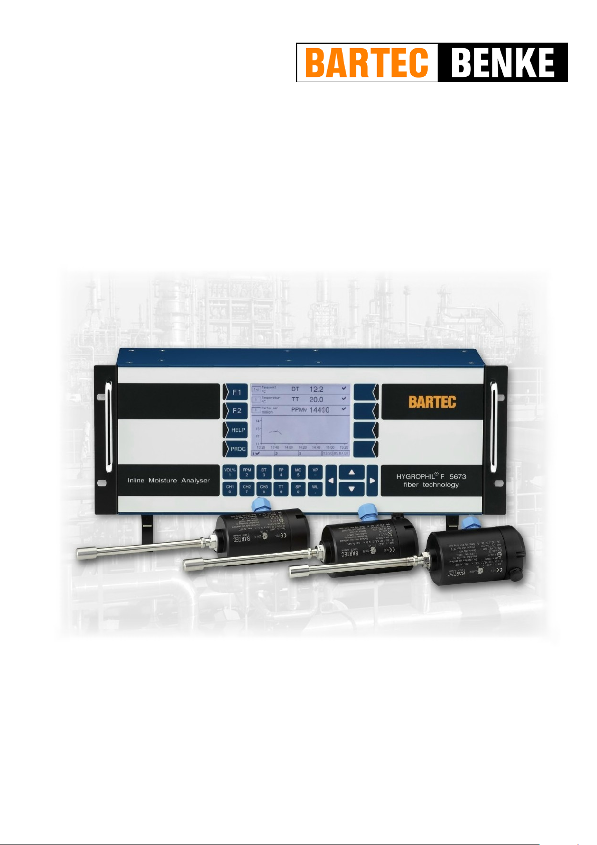
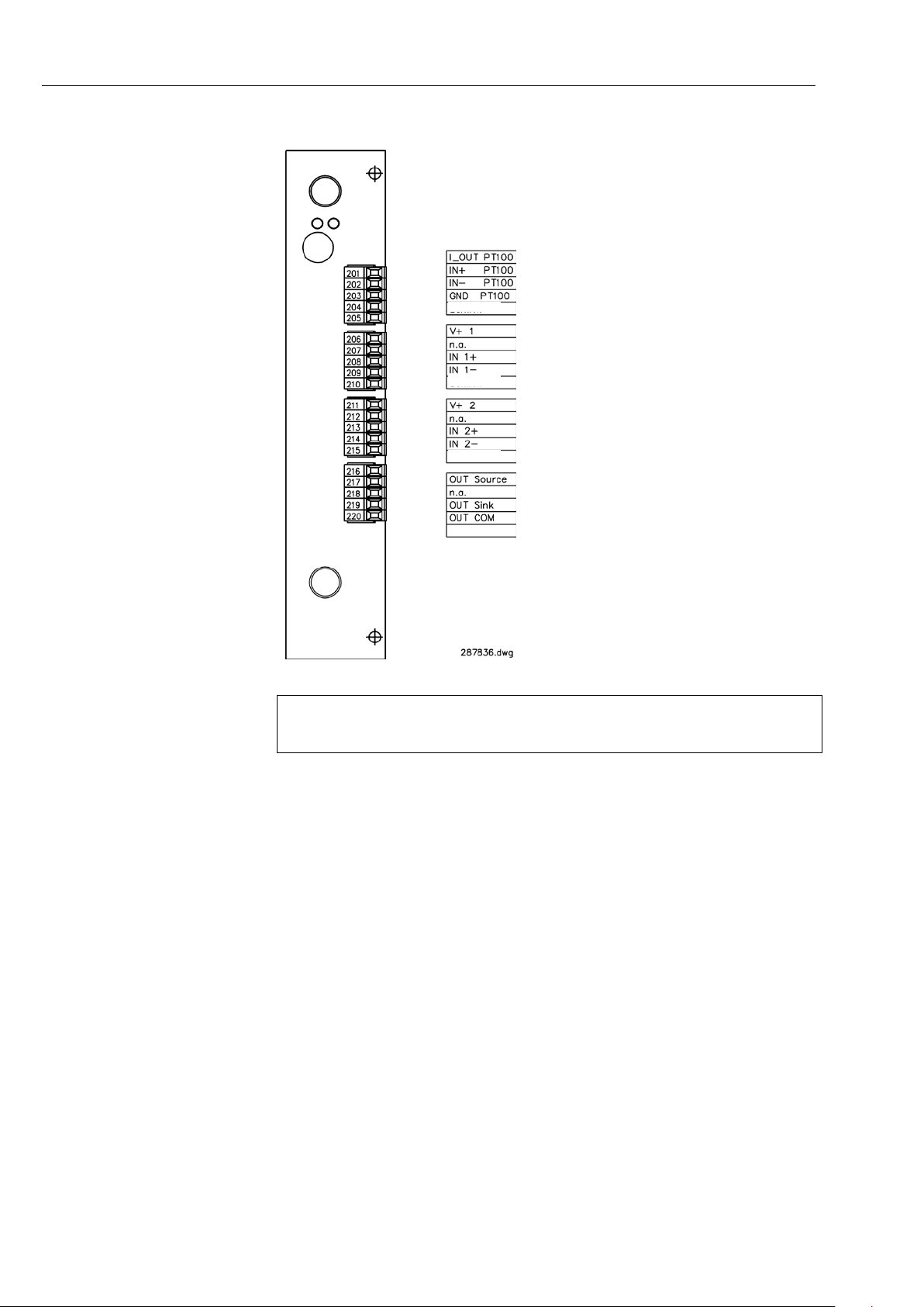
HYGROPHIL® F 5673
Series A
Operating manual
Software version 1.8.x
387896MDHEN
BARTEC BENKE GmbH Schulstraße 30 94239 Gotteszell Deutschland Telefon +49(0)9929)-301-0 Telefax +49(0)9929)-301-112
E-Mail: [email protected] Internet: www.bartec-benke.de
Page 2

Page 3

Contents
C - 1
Contents
Contents Page Issue date
System description ____________________________________________ 1-1
1
1.1 Measurement principle, Function and applications _____________________ 1-1 09.11.2011
1.2 Declaration of Conformity ________________________________________ 1-2 19.05.2011
1.3 Layout of the humidity measurement system _________________________ 1-4
1.3.1 Operator controls and display elements _____________________________ 1-4
1.3.1.1 Keyboard _____________________________________________________ 1-4
Key functions __________________________________________________ 1-5 26.04.2013
1.3.1.2 Display ______________________________________________________ 1-7 17.03.2011
1.3.2 Interfaces ____________________________________________________ 1-8 17.04.2013
1.4 Technical data ________________________________________________ 1-11
1.4.1 Evaluation unit F 5673 _________________________________________ 1-11
1.4.2 CPU plug-in unit type 5673-113 __________________________________ 1-12
1.4.3 Power supply plug-in unit DC 10..36V type 5673-108 _________________ 1-12 19.05.2011
1.4.4 Power supply plug-in unit AC 100..240V type 5673-109 _______________ 1-12
1.4.5 Analog I/O Ex type 5673-114 ____________________________________ 1-13
1.4.6 Interface module type 5673-110 __________________________________ 1-15 17.04.2013
1.4.7 Relay-Interface module Type 5673-115 ____________________________ 1-17 19.05.2011
1.4.8 Polychromator plug-in unit type 5673-302 __________________________ 1-18
1.4.9 Humidity sensor L166x _________________________________________ 1-18 17.04.2013
1.5 Spare parts, accessories _______________________________________ 1-20 14.06.2013
2 Safety precautions ____________________________________________ 2-1
3 Installation ___________________________________________________ 3-1
3.1 General ______________________________________________________ 3-1
3.2 Arrangements for EMC __________________________________________ 3-1
3.3 Sensor L166x _________________________________________________ 3-2
3.3.1 Wiring the sensor L166x _________________________________________ 3-2 17.04.2013
3.3.2 Installing the sensor L166x _______________________________________ 3-6
3.3.2.1 Installing accessories ___________________________________________ 3-6
3.3.2.2 Assembly examples ____________________________________________ 3-6 20.04.2012
3.3.3 Installation advice _____________________________________________ 3-13
4 Operation ____________________________________________________ 4-1
4.1 Start up ______________________________________________________ 4-1
4.2 Automatic sensor equalizing ______________________________________ 4-1 02.11.2011
4.3 Display modes _________________________________________________ 4-2 17.03.2011
4.3.1 Combined display ______________________________________________ 4-3
4.3.1.1 Selecting a line ________________________________________________ 4-3
4.3.1.2 Assigning a channel ____________________________________________ 4-4
4.3.1.3 Assigning a measurement variable _________________________________ 4-4 26.04.2013
4.3.1.4 Fixed values __________________________________________________ 4-5
4.3.1.5 Status indication _______________________________________________ 4-5
4.3.1.6 Graphic ______________________________________________________ 4-5
4.3.1.7 Info line ______________________________________________________ 4-5
4.3.2 Measurement value display with six lines ____________________________ 4-6
4.3.3 Measuring the humidity in liquids __________________________________ 4-6
4.3.4 Online graphic display ___________________________________________ 4-7
4.3.5 History graphic display __________________________________________ 4-8
4.3.5.1 History Setup __________________________________________________ 4-8 17.03.2011
Defining the presentation period ___________________________________ 4-9 17.03.2011
Defining the presentation of the graph _____________________________ 4-10
4.3.5.2 Display the history graphic ______________________________________ 4-12
Hide Graphs _________________________________________________ 4-12 17.03.2011
Changing the display mode _____________________________________ 4-13 17.03.2011
HYGROPHIL® F 5673 Operating manual, Software version 1.8.x, 387896MDHEN(14.06.2013)
Page 4

Contents
C - 2
Contents Page Issue date
4.4 Data export __________________________________________________ 4-14
4.4.1 Copy data ___________________________________________________ 4-14 17.03.2011
4.4.2 Converting data ______________________________________________ 4-15
4.4.3 Export service information to an external data medium ________________ 4-16 17.03.2011
5 Programming _________________________________________________5-1
5.1 General instructions _____________________________________________5-1
5.2 Calling up programming mode _____________________________________5-2
5.3 Selecting and opening the menu ___________________________________5-3
5.4 Editing parameters ______________________________________________5-4
5.4.1 Selecting the parameter setting ____________________________________5-4
5.4.2 Selecting the parameters for editing _________________________________5-5
5.4.3 Numerical entries _______________________________________________5-5
5.5 Structure of the programming menu _________________________________5-6 20.04.2012
5.6 Program parameters___________________________________________ 5-12
5.6.1 Dimension units ______________________________________________ 5-12
5.6.2 Analog outputs _______________________________________________ 5-13
5.6.3 Analog inputs ________________________________________________ 5-16
5.6.3.1 Temperature _________________________________________________ 5-16 17.03.2011
5.6.3.2 Pressure ____________________________________________________ 5-17 17.03.2011
5.6.3.3 CO2 content _________________________________________________ 5-17 17.03.2011
Default values ________________________________________________ 5-17
5.6.4 Limits ______________________________________________________ 5-18
5.6.5 Selecting the MC Calculation Method _____________________________ 5-19 02.11.2011
DIN EN ISO 18453 ____________________________________________ 5-20
Custom User Factor ___________________________________________ 5-21
5.6.6 Edit Gas Data ________________________________________________ 5-22 02.11.2011
5.6.6.1 Predefined gases _____________________________________________ 5-23 09.11.2011
5.6.6.2 User specific gases ___________________________________________ 5-24
Create a user specific gas ______________________________________ 5-24
Edit a user specific gas ________________________________________ 5-27
Delete a user specific gas ______________________________________ 5-28
5.6.7 Modbus/Profibus ______________________________________________ 5-29 29.03.2011
5.6.8 Date and time ________________________________________________ 5-30
5.6.9 Serial output _________________________________________________ 5-31 17.03.2011
5.6.10 Assigning a liquid to a channel ___________________________________ 5-32
5.6.10.1 Default curves ________________________________________________ 5-33
5.6.10.2 User specific curves ___________________________________________ 5-34
5.6.11 Edit Liqiuid Curves ____________________________________________ 5-34
5.6.11.1 Default curves ________________________________________________ 5-34
5.6.11.2 User specific curves ___________________________________________ 5-35
Create a new curve ___________________________________________ 5-35
Edit a curve __________________________________________________ 5-39
Delete a curve _______________________________________________ 5-39
5.6.12 Offset ______________________________________________________ 5-39
Cancel offset _________________________________________________ 5-40
5.6.13 Reset configuration to default ____________________________________ 5-41 17.03.2011
5.6.14 Language ___________________________________________________ 5-42 02.11.2011
5.6.15 System Information____________________________________________ 5-43 09.11.2011
Export service information to an external data medium ________________ 5-43 09.11.2011
5.6.16 Change Password ____________________________________________ 5-44
5.6.17 Maintenance menu ____________________________________________ 5-44
HYGROPHIL® F 5673 Operating manual, Software version 1.8.x, 387896MDHEN(14.06.2013)
Page 5

Contents
C - 3
Contents Page Issue date
6 Error handling ________________________________________________ 6-1
6.1 Limit transgressions ____________________________________________ 6-1
6.2 Warnings _____________________________________________________ 6-2
6.3 Errors _______________________________________________________ 6-2
6.4 HELP key ____________________________________________________ 6-3
7 Maintenance _________________________________________________ 7-1
Cleaning the sensor ____________________________________________ 7-1 17.04.2013
8 Bus systems _________________________________________________ 8-1
8.1 Modbus ______________________________________________________ 8-1 26.04.2013
8.2 Profibus ______________________________________________________ 8-6 04.06.2012
9 Appendix ____________________________________________________ 9-1
List of resistance and side effects for fibre-optic sensor L166x ___________ 9-1
Default liquid saturation characteristic curves in HYGROPHIL® F 5673 ____ 9-3
Predefined gases in HYGROPHIL® F 5673 __________________________ 9-5 09.11.2011
HYGROPHIL® F 5673 Operating manual, Software version 1.8.x, 387896MDHEN(14.06.2013)
Page 6
Contents
All rights reserved and subject to change.
written consent of BARTEC BENKE.
Copyright © 2015
by BARTEC BE
Schulstraße 30,
D-94239 Gotteszell
Document: 387896MDHEN valid from: 10.11
C - 4
Duplication, processing and distribution of this document,
including parts thereof, is prohibited without the prior
NKE GmbH
Revision: Software version 1.8.x 14.06.2013
Author: G. Rothe
Translation E. Bau ernf eind
HYGROPHIL® F 5673 Operating manual, Software version 1.8.x, 387896MDHEN(14.06.2013)
Page 7

System description
1 System description
1.1 Measurement principle, Function and applications
HYGROPHIL® F 5673 is a high-quality, m icroprocess or-controlled fibr e-optic
hygrometer for measuring the moisture or trace humidity at low dew-point
temperatures in gases and liquids.
®
HYGROPHIL
compensated fibre-optic sensor developed especially for measuring the
moisture content in gas mixtures and liquids.
Measurement of water dew point temperature
(Gas humidity)
The water dew point is m easured with the HYGROPHI L® F and sensor type
L166x.
The moisture s ensor, type L166x, cons ists of a robust multi-layer of optically
high and low refractive layers connected to 2 fibre-optical cables.
Due to a special ther m al coating tec hni que, por es with t he diam eter of a water molecule are generated on the layer.
Due to the moisture e quilibrium cont ent, water is depos ited in the layer and
changes the refractive index of the irradiating light (air: 1,00/water 1,33).
Within the layer s ystem this results in a wavelength s hift in pro portion to the
moisture prevailing in the medium.
This shift is measured by the evaluation unit and assigned to a dew point.
The L166x probe makes measurements which are temperature compensated (by the integrated Pt100).
In short, the H YGROPHIL
sensor which fibre-optic ally determines the moisture c ontent and measures
the temperature in the medium with a Pt100.
Apart from the extremely robust construction of the sensor, it is above all
else, the measurement technique which offers several decisive advantages.
F 5673 works in multi-channel oper ation with a temperatur e-
®
F 5673 work s in conjunction with a combination
1-1
Some of the advantages of this patented measuring method are as follows:
● High measuring confidence, including precision, reproducibility and low
hysteresis.
● Long-term stability of the sensor (no drift! )
● Measurement is possible on the high-pressure side (pressure dew point!)
● Application in explosive areas (zone 0 and higher)
● Simple installation and upgrading (Swagelok, Parker, …)
The L166x was developed espec ially for nat ural gas applicati ons and is now
applied in trace moistur e measurem ent for a large num ber of diff erent gases
and liquids.
Due to the usage of high-quality materials, the sensor is extremely robust
HYGROPHIL® F 5673 Operating manual, Software version 1.8.x, 387896MDHEN(14.06.2013)
and resistant to most media.
Page 8
System description
1-2
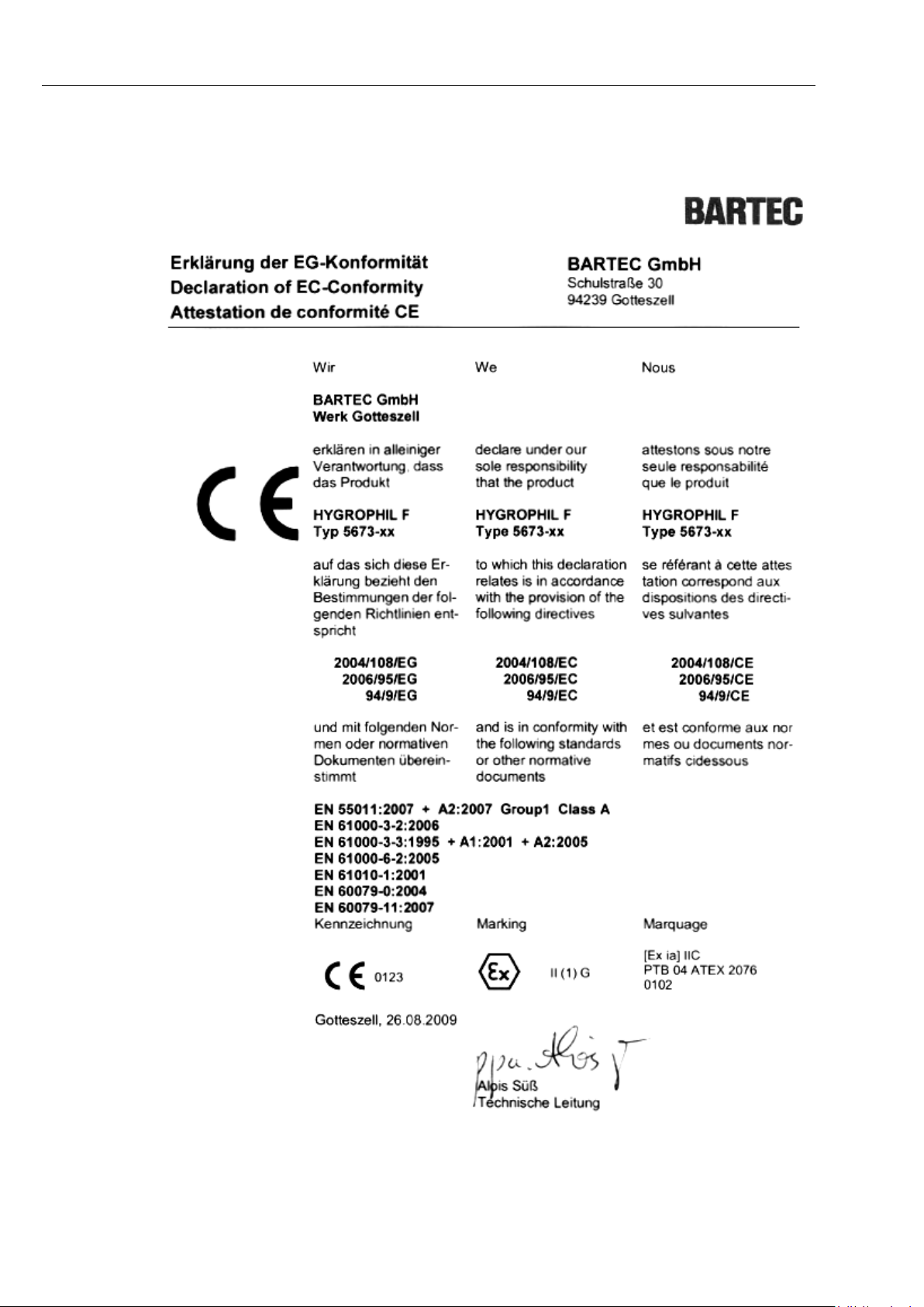
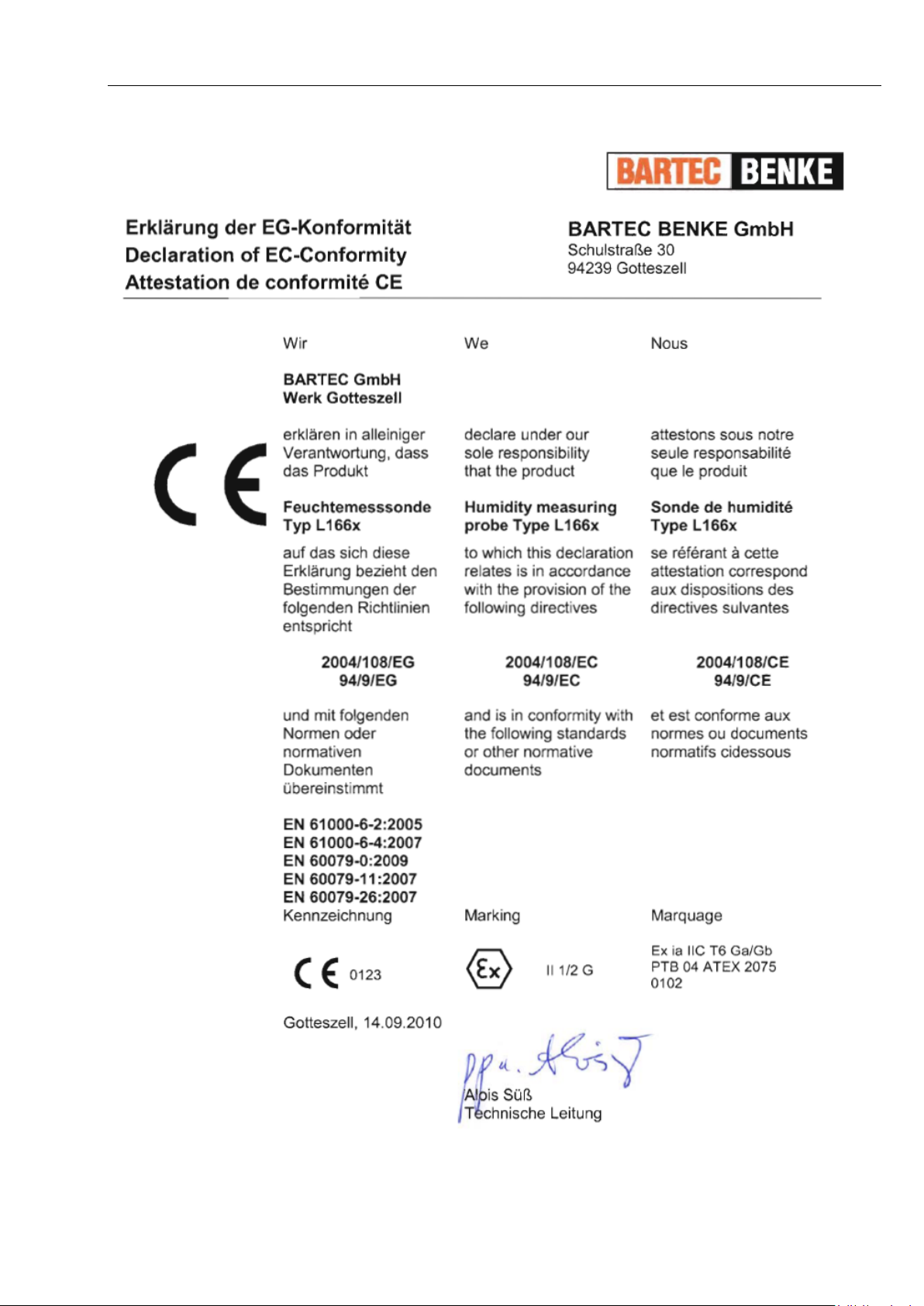
1.2 Declaration of Conformity
HYGROPHIL® F 5673 Operating manual, Software version 1.8.x, 387896MDHEN(14.06.2013)
Page 9
System description
1-3
HYGROPHIL® F 5673 Operating manual, Software version 1.8.x, 387896MDHEN(14.06.2013)
Page 10
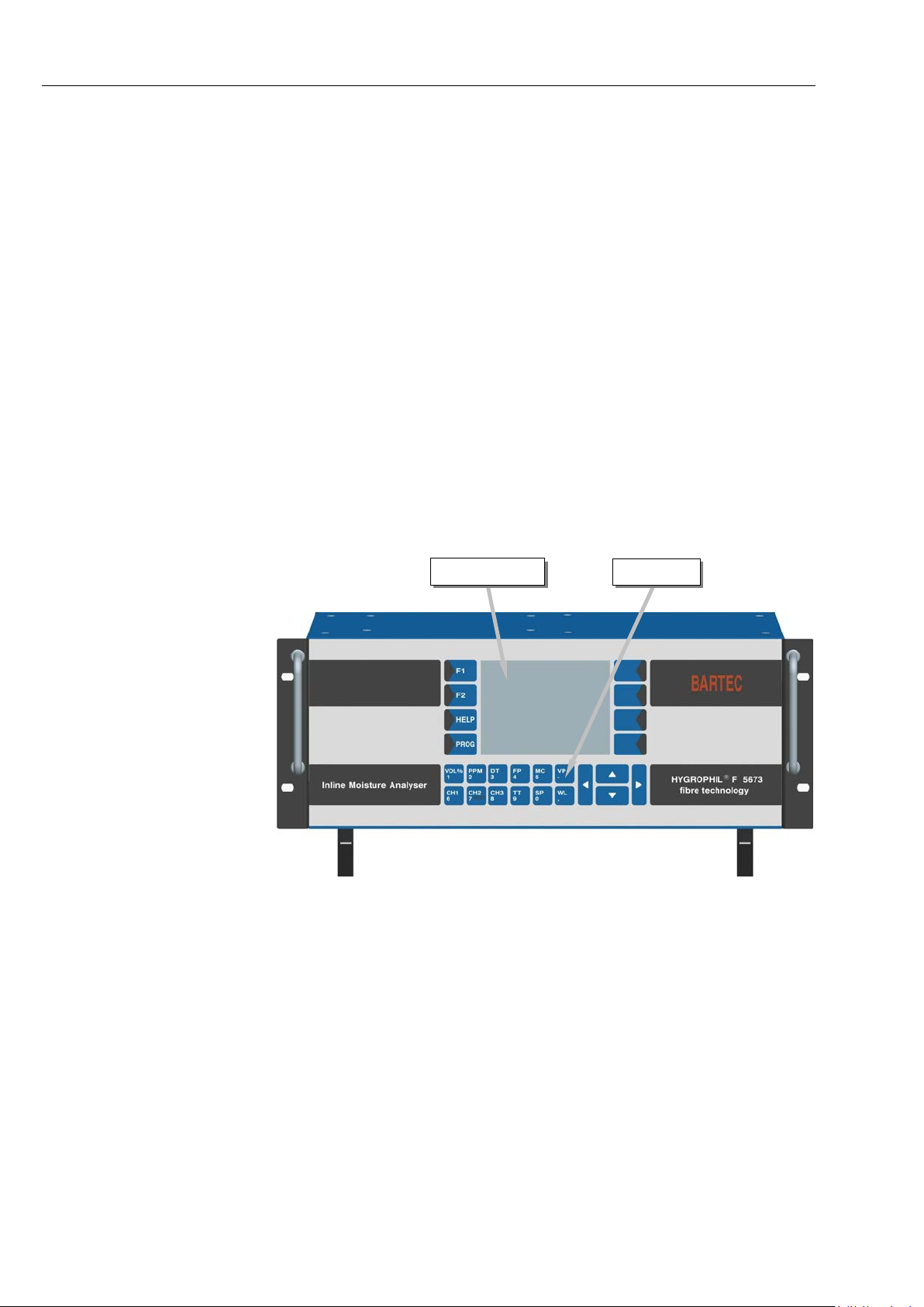
System description
Display
Keyboard
HYGROPHIL® F 5673, front view
1-4
1.3 Layout of the humidity measurement
1.3.1 Operator controls and display elements
system
The measurem ent system consist s of an evalu ation unit and up to thre e humidity sensors.
The evaluation un it is designed as a 19“rack which can tak e several plug-in
units. The evaluation unit can also be installed as a desktop device.
The humidity sensor consists of a sensor layer and an i ntegrated temperature sensor, the fibre-optic cable and the plug connector, which also contains
the sensor´s adjustment data.
The humidity sensor is available in three standard dimensions: 36
100 mm and 225
able on request.
All operator contr ols and d i s play elements are at th e f r ont side of the evaluation unit. The device is not equipped with a mains switch. If required, you
have to disconnect the device f rom the m ains supply (m ains plug). If operated as a desktop device, th e two f ront feet of the eva luatio n uni t ca n be s wivelled out for easier operation and a better viewing angle.
mm. Sensors with length of 407mm and 458mm are avail-
mm,
1.3.1.1 Keyboard
HYGROPHIL® F 5673 Operating manual, Software version 1.8.x, 387896MDHEN(14.06.2013)
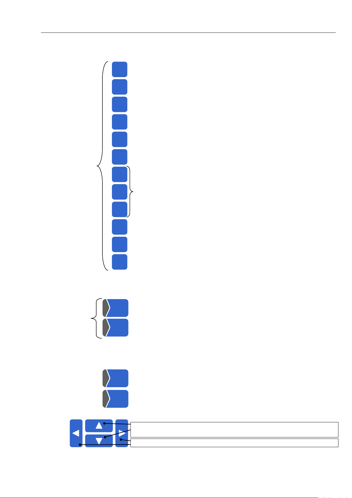
The device is operated via touch-sensitive k eys on the front side of the device (numeric and m easure ment varia ble k eys) and vi a certain k ey functi ons
of the touch-screen. All k eys are touc h-sens itive, i.e. you don ’t need to pr ess
them, only touch them.
Page 11
System description
(1)
VOL%
1
PPM
2
DT 3 FP 4 MC
5
VP
-
CH1
6
CH2
7
CH3
8
TT
9
SP 0 WL
,
(2)
F1
F2
HELP
PROG
1-5
Key functions
Indication of the water va pour conte nt [Vol%], opt ional relative hum idity [RH]
(see section 4.3.1.3)
per million weight
Indication of the Dewpoint Temperature
Indication of the Frost Point Temperature
Indication of the water vap our content in parts per million volume or in par ts
3
Indication of the Moisture Content [mg/m
] or [lb/MMscF]
Indication of the water Vapour Pressure
Selection of the measurement channel (see section 4.3.1.2)
Indication of the temperature at the measuring point (True Temperature)
Indication of the pressure at the measuring point (Sample Press ur e)
Indication of the Wave Length
In the entering mode or programming mode, these keys serve to enter
(1)
numerical values.
Trigger the sensor equalizing (see section 4.2)
Call up the history setup (see section 4.3.5.1)
Switch from online graphic mode to history graphic mode (see section 4.3)
(2) If these two keys are not labelled with F1 and F2 at your m easuring de-
vice, this does not m ean its f unctional range is restricted. T he function of
the keys is availab le anyhow.
Display of warnings and error messages
Call up the programming mode (see section 5.2)
Selection keys (see section 5.3
Switch between the display modes (see section 4.3)
),
Change the cursor position in entry fields (see section 5.4.3)
HYGROPHIL® F 5673 Operating manual, Software version 1.8.x, 387896MDHEN(14.06.2013)
Page 12
System description
1-6
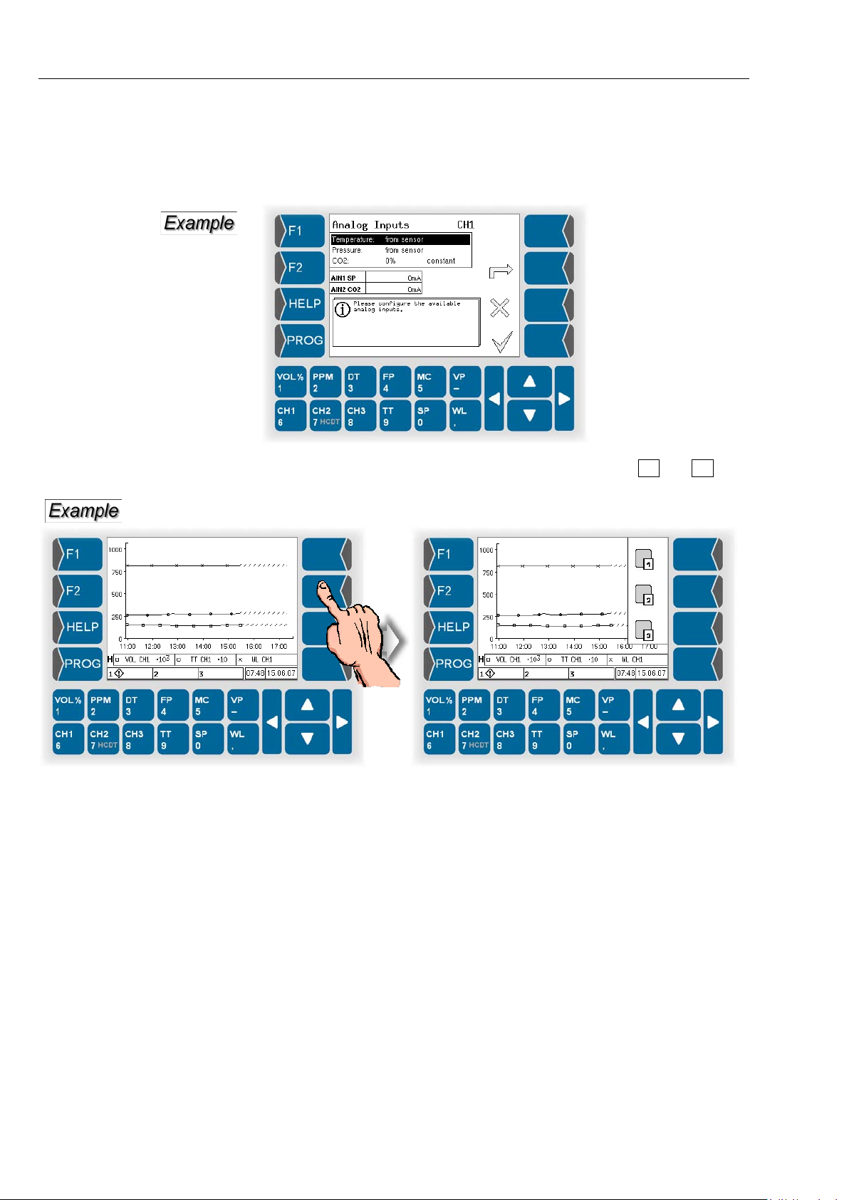
The four ke ys to the right of the displa y are not labelled. Depen ding on the
operating status of the measurement system, different functions are assigned to them. T he current function is m arked by a symbol next to the key
in the display (for the meaning of the symbols see section 5.1).
In several operating situ ations is the current functio n of the F1 and F2 keys
as well as the four keys to the righ t of the display only displayed when touc hing one of these keys.
When the function is displayed you can start the function by touching this
key.
HYGROPHIL® F 5673 Operating manual, Software version 1.8.x, 387896MDHEN(14.06.2013)
Page 13
1.3.1.2 Display
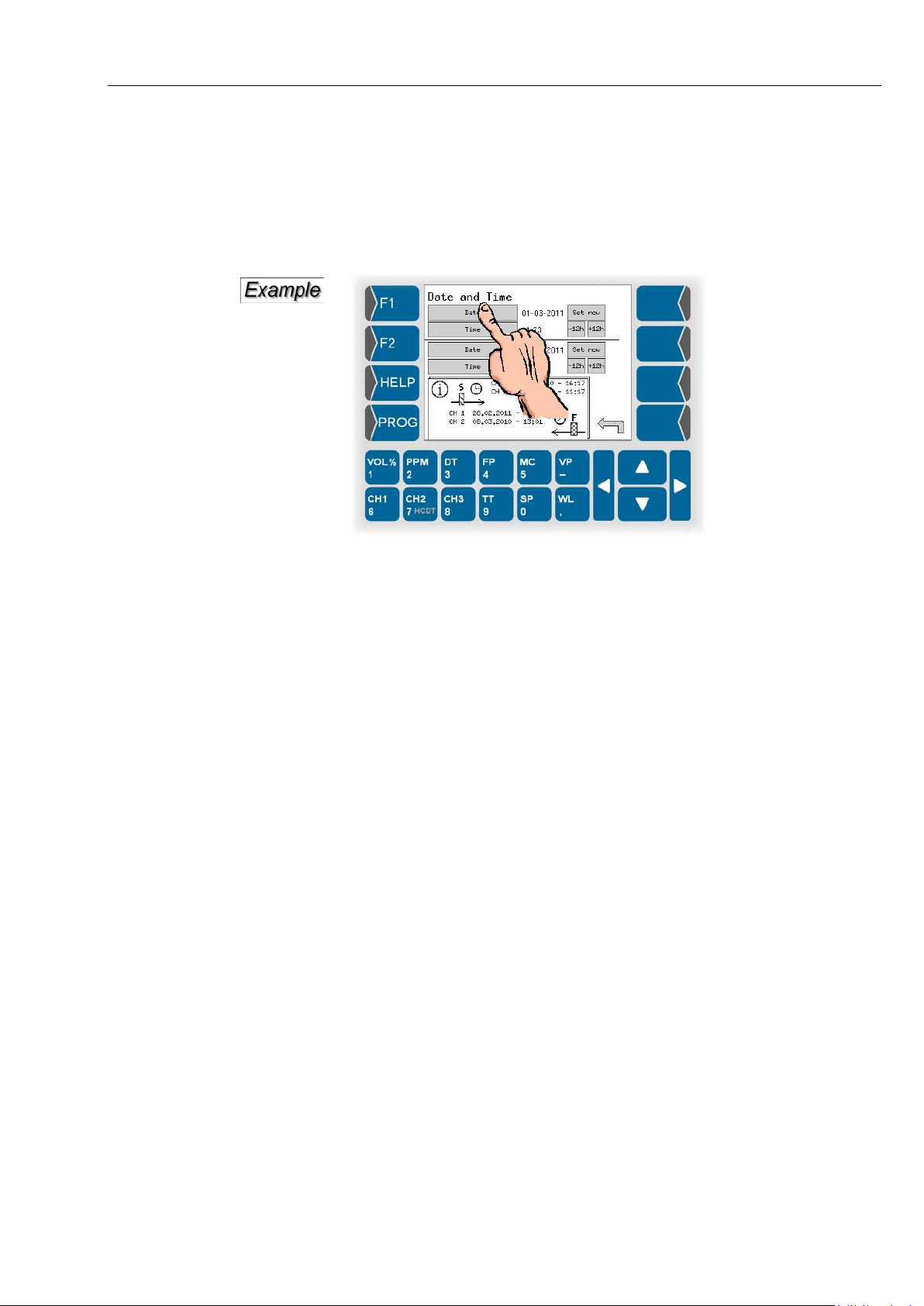
A graphic display screen designed as a touch-screen is used for display
purposes.
Some functions are operated by means of key functions loc ated on the display screen in dependence on the situation.
System description
1-7
HYGROPHIL® F 5673 Operating manual, Software version 1.8.x, 387896MDHEN(14.06.2013)
Page 14
System description
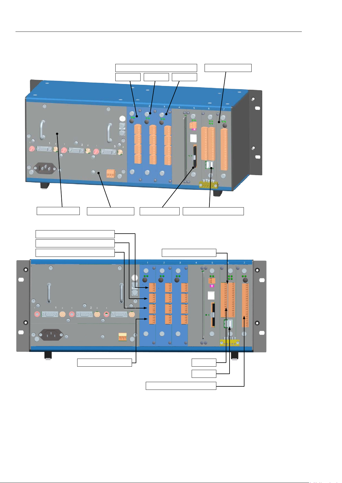
Polychromator
Channel boards Analog/Digital I/O Ex
Relay module
Power supply module
CPU module
Interface module
Channel 1
Channel 2
Channel 3
Current output Ex i
Temperature sensor (PT100)
Pressure sensor (4...20 mA)
CO2-sensor (4...20 mA)
COM
USB
Relay outputs see section 1.4.7
3x Current output
1-8
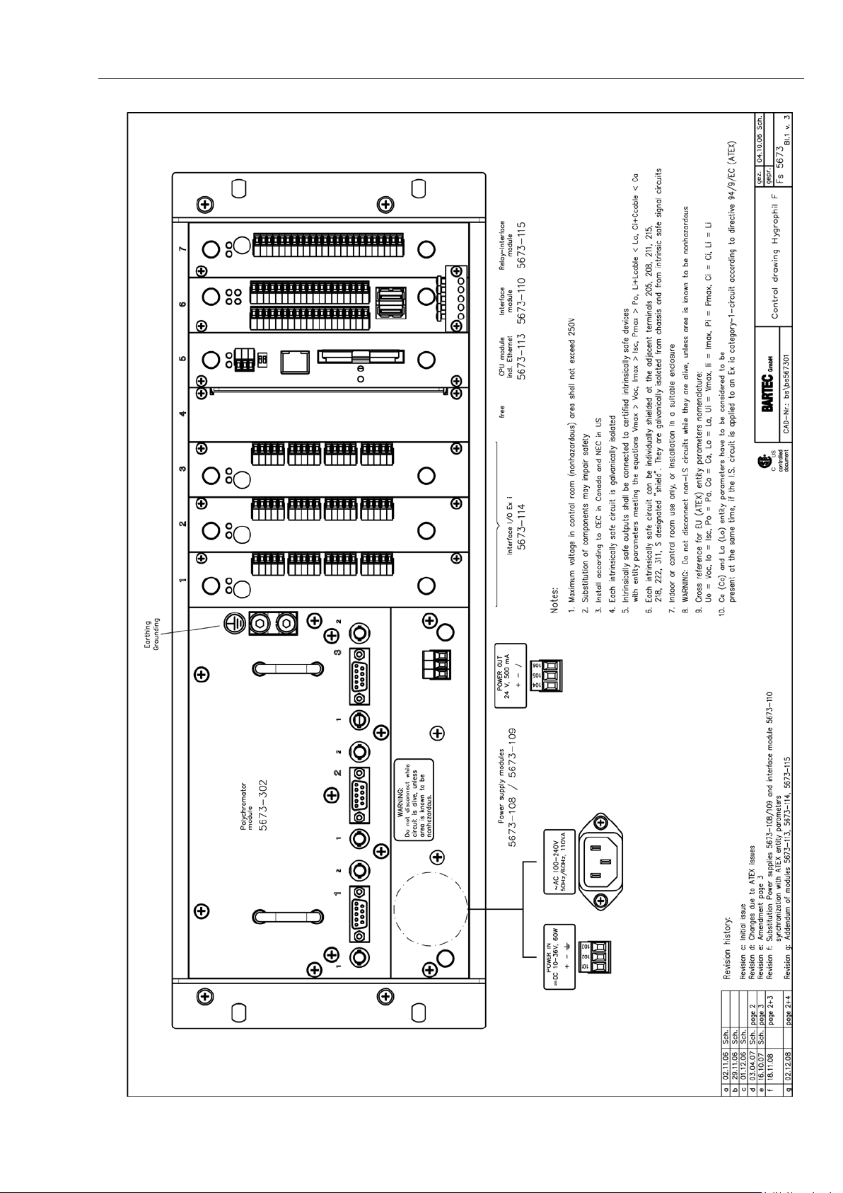
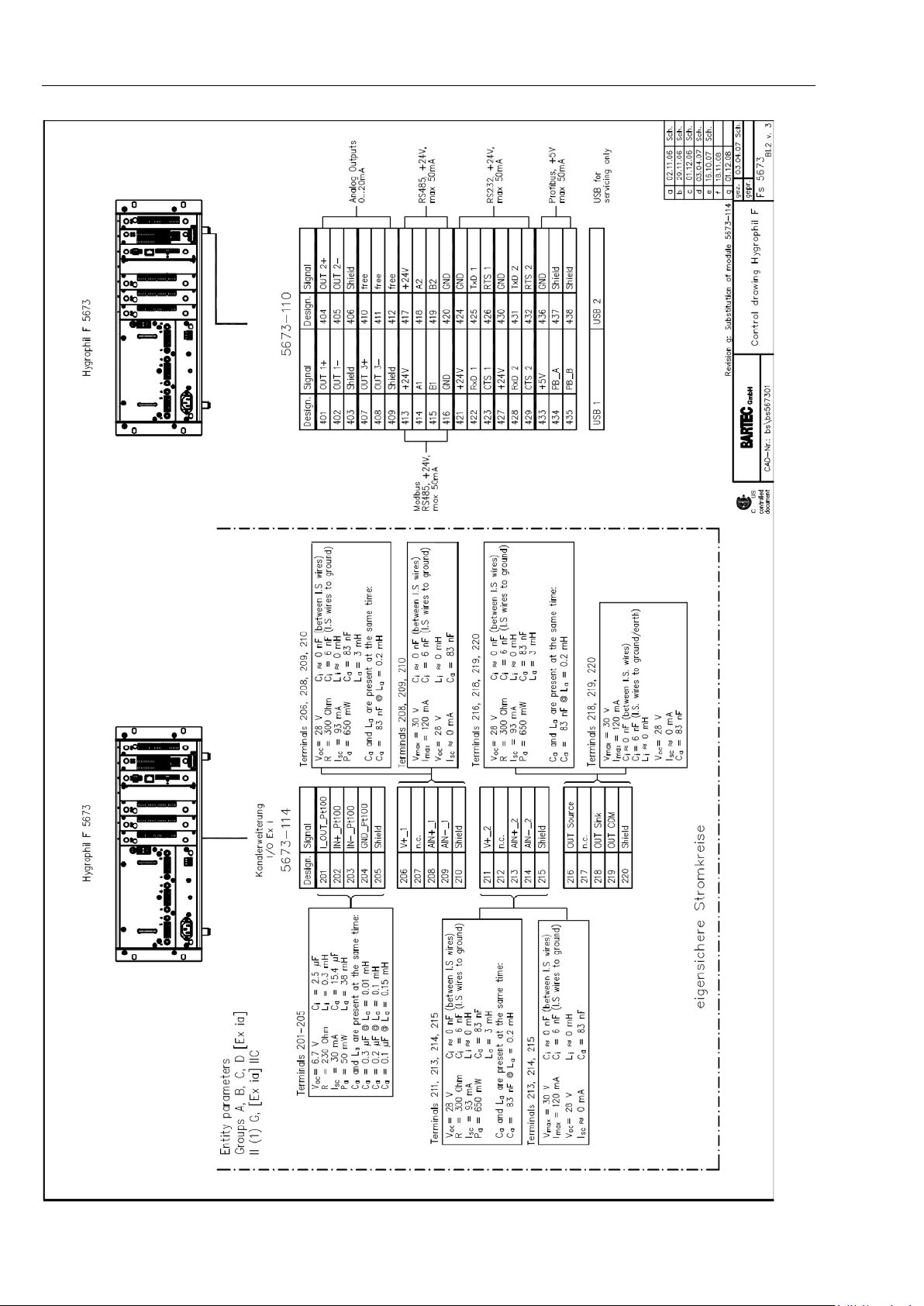
1.3.2 Interfaces
HYGROPHIL® F 5673 Operating manual, Software version 1.8.x, 387896MDHEN(14.06.2013)
Page 15
System description
1-9
HYGROPHIL® F 5673 Operating manual, Software version 1.8.x, 387896MDHEN(14.06.2013)
Page 16
System description
Interface
1-10
module
HYGROPHIL® F 5673 Operating manual, Software version 1.8.x, 387896MDHEN(14.06.2013)
Page 17
1.4 Technical data
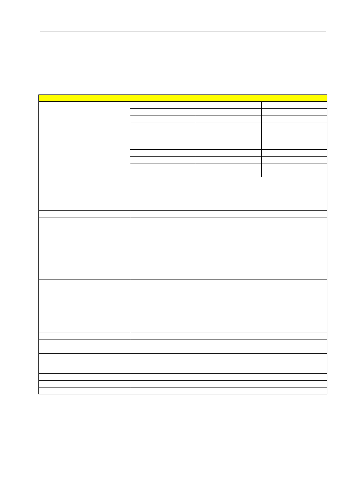
Evaluation unit
Display ranges
Measurement variable
Lower range limit
Upper range limit
Vol% [%]
0
100
PPM [ppm]
0
25000
DT [°C,°F,K]
-100
100
FP [°C,°F,K]
-100
100
MC [mg/m3],
[lb/MMscF]
0
30000
VP [hPa]
0
250
TT [°C,°F,K]
-50
100
SP [bar,PSI,..]
0
250
WL [nm]
780
830
Auxiliary variables
The temperature (T T) at the m easuring p oint is m eas ured via a s ensor i nte-
signal or entered by hand.
Measurement channels
1, 2 or 3
Measuring rate
Max. 3 measurements / minute per channel
Inputs per measurement channel
- Light waveguide port for optical hum idity sensor
all inputs Ex ia, galvanically isolated
Analog outputs per measurement
Clamp-type terminal 0/4...20 mA, EEx ia, galvanically isolated
Temperature drift: <0.001 mA/ °C
Interfaces
RS 232, modbus, profibus
Display
Graphic display 320 x 240 dots
Keyboard
Red backlit touch-screen
Auxiliary energy
DC 10...36 V max. 60 W (Si 6.3 A T)
AC 100...240 V max. 110 VA (Si 3.15 A MT)
Ambient conditions
Permissible working temperature: 0...+50 °C
Climatic category: IWI according to DIN 40040
Dimensions (WxHxD)
483 x 192 x 212
Approvals
ATEX, CSA, GOST
Weight
approx. 8.5 kg
1.4.1 Evaluation unit F 5673
(not the measuring range)
System description
1-11
grated in the humidity sensor or entered by hand. The pressure (SP) is
measured via a 4...20 mA signal from an external pressure transmitter or
entered by hand. CO
-content (0...100%) is measured via a 4...20 mA-
2
channel
- 9-pole D-SUB plug for data memory with sensor characteristic
- Clamp-type terminal for PT 100 measurement sensor in sensor head
- Clamp-type terminal for signal from a pressure transmitter for absolute
pressure (4...20 mA)
- Clamp-type terminal for CO
Source and sink
Resolution 0.0003 mA
Max. load: 500 Ω
Accuracy: 0.03 mA
Permissible storage temperature: -20...+60 C
content (4...20 mA)
2
HYGROPHIL® F 5673 Operating manual, Software version 1.8.x, 387896MDHEN(14.06.2013)
Page 18
System description
Electrical data
Operating voltage CPU
5.5 V ± 2 %
Power consumption
800 mA
Fuse of battery
3.5 A
Interfaces
USB 2.0 Host
OHCI
Ethernet
100 MBit
5x up to 115200 Bit/s, 3.3 V LVTTL
2x up to 460800 Bit/s, 3.3 V LVTTL
Elektronics
Realtime clock
32.768 kHz (batter y buff ered)
Ambient conditions
Operating temperature
- 10 … + 50 °C
Storage temperature
- 20 … + 70 °C
Climatic class
JWF in accordance with DIN 40040
Protection type
IP00 in accordance with DIN 40050
Electrical data
Input voltage
DC 10...36 V, fuse 6.3 A (T)
5,5 V 3.2 A short-circuit-proof
10 V max. 100 mA
Maximum output power
60 W
Ambient conditions
Operating temperature
- 10 … + 50 °C
Storage temperature
- 20 … + 70 °C
Electrical data
Input voltage
AC 100...240 V, fuse 3.15 A (MT)
5.5 V 3.2 A short-circuit-proof
10 V max. 100 mA
Maximum output power
110 VA
Ambient conditions
Operating temperature
- 10 … + 50 °C
Storage temperature
- 20 … + 70 °C
1-12
1.4.2 CPU plug-in unit type 5673-113
Serial interfaces
1.4.3 Power supply plug-in unit DC 10..36V
Output voltage
1.4.4 Power supply plug-in unit AC 100..240V
Output voltage
type 5673-108
24 V 1.2 A short-circuit-proof
type 5673-109
24 V 1.2 A short-circuit-proof
HYGROPHIL® F 5673 Operating manual, Software version 1.8.x, 387896MDHEN(14.06.2013)
Page 19
1.4.5 Analog I/O Ex type 5673-114
Electrical data
Operating voltage for CPU
DC 5.5 V ± 2 % 200 mA, fuse 400 mA
Operating voltage for sensor supply
DC 24 V ± 5 %, max. 480 mA, fuse 1 A
PT-100 [EEx ia]
Type
Pt-100 (4 wires), l 1 mA -50...+100 °C
Resolution
0.005 °C (16 bit)
Separation
galvanically isolated
Analog Output [EEx ia]
Current range
0/4-20 mA
resolution
0.0003 mA
Separation
galvanically isolated
Sampling
Max. 10 /s
Aktive
Load max. 500 Ω
Passive
U
max
:36 V, U
min
at 20 mA: 8 V
Analog Input [EEx ia]
Quantity
2
Input current
4...20 mA
Resolution
0.005 mA
Separation
galvanically isolated
Sampling
Max. 10 /s
output voltage V+1 and V+2
DC 24 V ±10% max. 30 mA, short-circuit-proof
Ambient conditions
Operating temperature
- 10 … + 50 °C
Storage temperature
- 20 … + 70 °C
System description
1-13
HYGROPHIL® F 5673 Operating manual, Software version 1.8.x, 387896MDHEN(14.06.2013)
Page 20
System description
Analog I/O Ex
Shield
Shield
Shield
Shield
Shield
EMC:
1-14
Type 5673-114
To the cables of the an alog inputs IN1, IN2 and to the cabl e of the analog
output OUT Source mus t be fixed f errite noise f ilters ( order no. 27 536 8) (see
section 3.2).
HYGROPHIL® F 5673 Operating manual, Software version 1.8.x, 387896MDHEN(14.06.2013)
Page 21
System description
Electrical data
Operating voltage for CPU
DC 5,5 V ± 2 %
Operating voltage for interfaces
DC 24 V ± 5 %
3 x Analog output
Current range
0/4 – 20 mA, galvanically isolated, source
Resolution
0,0003 mA
Apparent ohmic resistance
< 800 Ω
Accuracy
± 0.15 %
Temperature drift
<0.001 mA/°C
2 x RS485
Functionality
Modbus
Output voltage for each interface
24 V ± 5 %, max. 50 mA
2 x RS232
Functionality
Logging
Output voltage for each interface
24 V ± 5 %, max. 50 mA
Profibus
Functionality
Profibus DB (Slave)
Output voltage for each interface
5V ± 2 %, max. 50 mA
2 x USB
Functionality
Standard USB interface
Only for service and maintenance purposes
Ambient conditions
Operating temperature
- 10 … + 50 °C
Storage temperature
- 20 … + 70 °C
1.4.6 Interface module type 5673-110
1-15
HYGROPHIL® F 5673 Operating manual, Software version 1.8.x, 387896MDHEN(14.06.2013)
Page 22
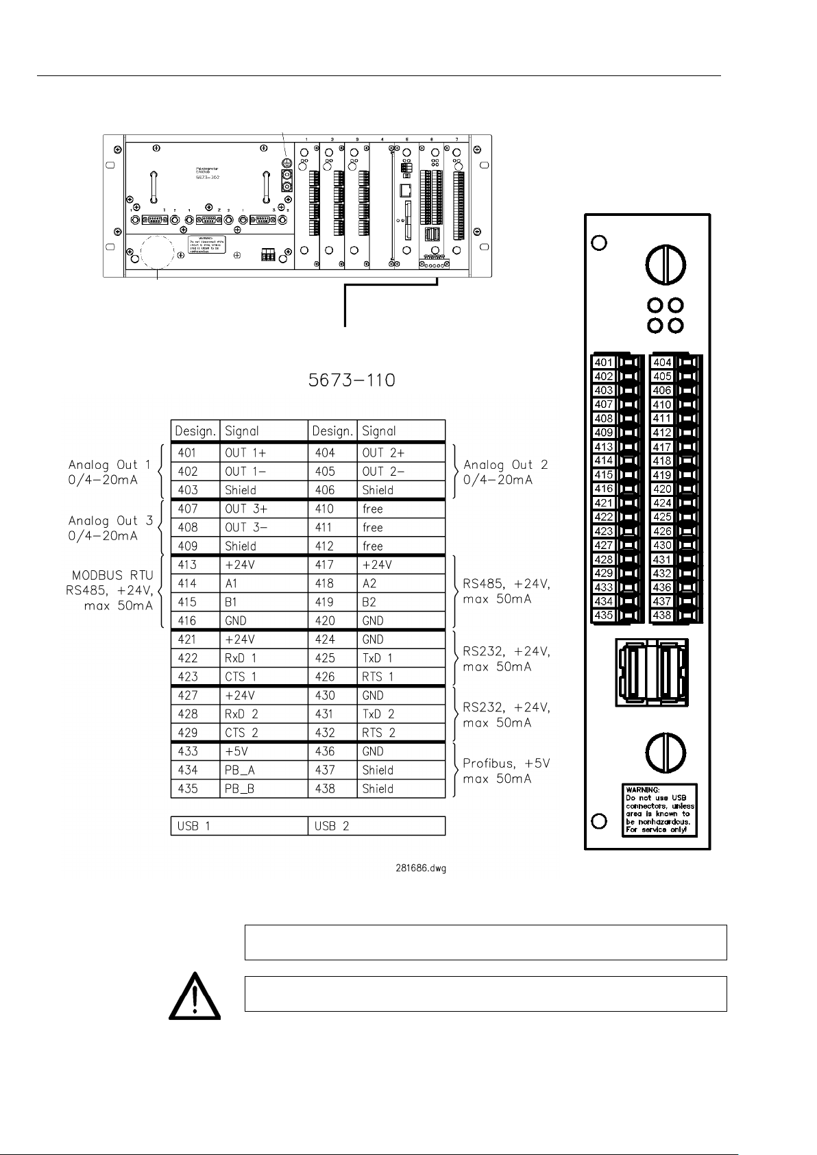
System description
Interface
module
MODBUS RTU
Serial Out (s. 5.6.9)
EMC:
1-16
Select the interface for MODBUS in the „Modbus/Profibus“ menu (see secti on 5.6.7).
To all cables of the analog outp uts O UT1, OUT 2, OUT3 must be fixed ferr ite
noise filters (order no. 275368) (see section 3.2).
Do not use USB connectors, unless area is known to be nonhazardous.
For service only!
HYGROPHIL® F 5673 Operating manual, Software version 1.8.x, 387896MDHEN(14.06.2013)
Page 23
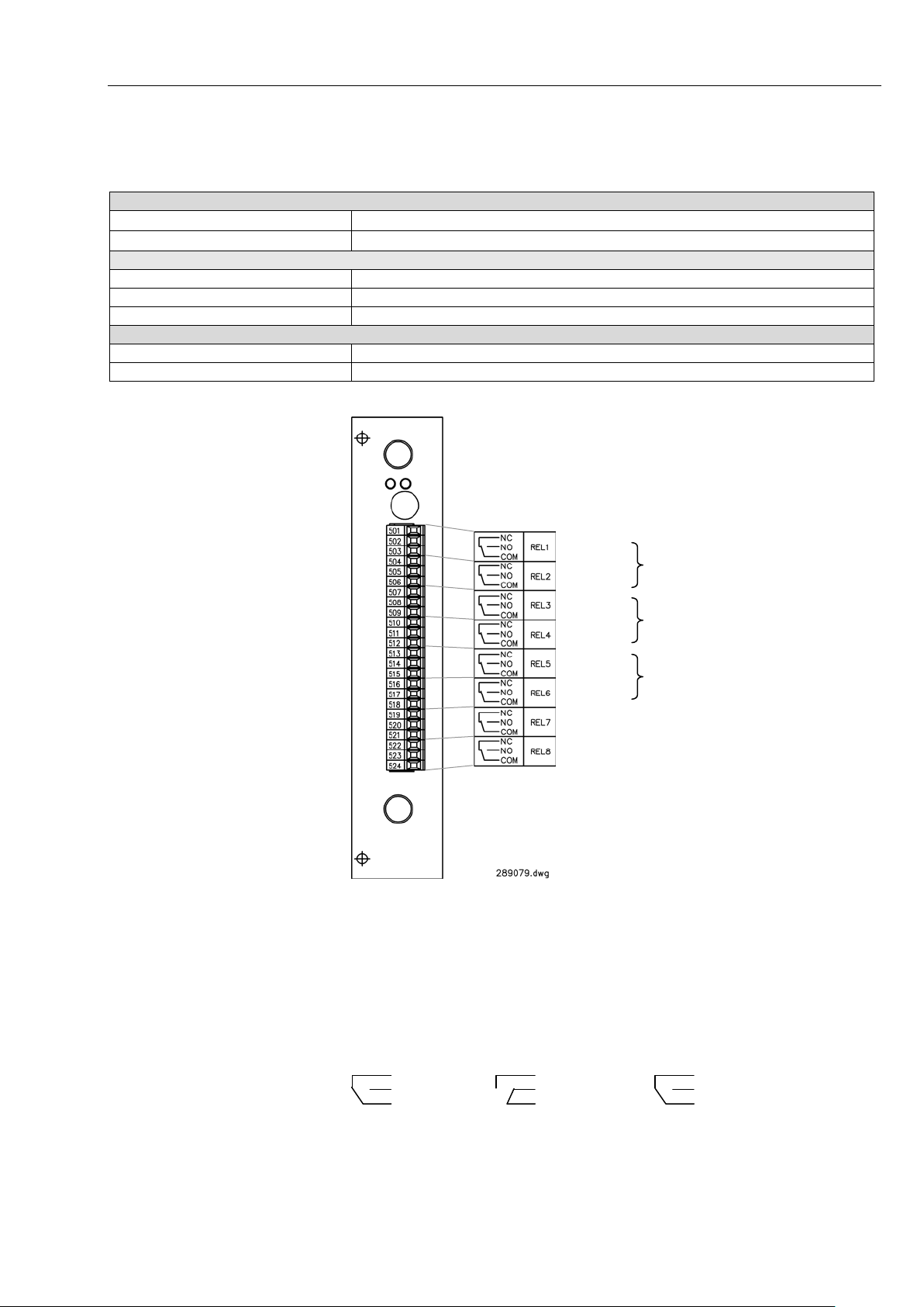
System description
Electrical Data
Operating voltage CPU
DC 5.5 V ± 2 % 70 mA fuse 500 mA
Operating voltage 24 V
DC 24 V ± 5 % 60 mA fuse F3A
Relays
Type
Change-over contact
Insulation
1500 vrms
Contacts
30V, 1A
Ambient conditions
Operating temperature
- 10 … + 50 °C
Storage temperature
- 20 … + 70 °C
Error
NC
NC
NC
Analyzer off
Analyzer on
Analyzer on
1-17
1.4.7 Relay-Interface module Type 5673-115
Limit
Channel 1
Error
Channel 2
Limit
Error
Channel 3
Limit
not used
not used
Switching operations:
From software version 1. 7.7 the switching operations hav e changed as follows: The relays are activated in normal operation and deactivated when
causing an ERROR- or LIMIT -signal.
NO
COM
no ERROR
no LIMIT
NO
COM
ERROR
LIMIT
NO
COM
HYGROPHIL® F 5673 Operating manual, Software version 1.8.x, 387896MDHEN(14.06.2013)
Page 24
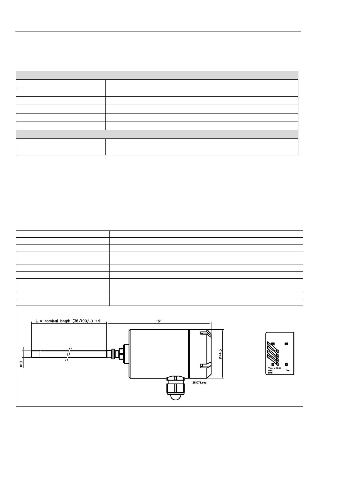
System description
Electrical data
Operating voltage
DC 5.5 V
Power consumption
200 mA
Connection type
ST plug optical (sensor)
Interface
USB 12 Mbit/s (full speed)
Measuring range
ca. 720...870 nm
Resolution
2000 Pixel ≅ 0.17 nm/Pixel
Ambient conditions
Storage temperature
-20…+60 °C
Permissible working temperature
-30...+60 °C
Permissible storage temperature
-30...+ 60 °C
Integrated Pt100
DIN IEC 751, 4-wire class A
Max. permissible working pressure
100 bar, 200 bar on request with certificate (gas-pressure test)
Calibrated Range
-80 … +20 °C DT
Accuracy
+/- 1 K
Material
Shaft: 1.4571
Sensor head: POM
Protection type
IP 65 (in built-in state)
Approvals
ATEX, CSA, CRN, GOST
Dimensions in mm
1-18
1.4.8 Polychromator plug-in unit type 5673-302
Operating temperature -10…+50 °C
1.4.9 Humidity sensor L166x
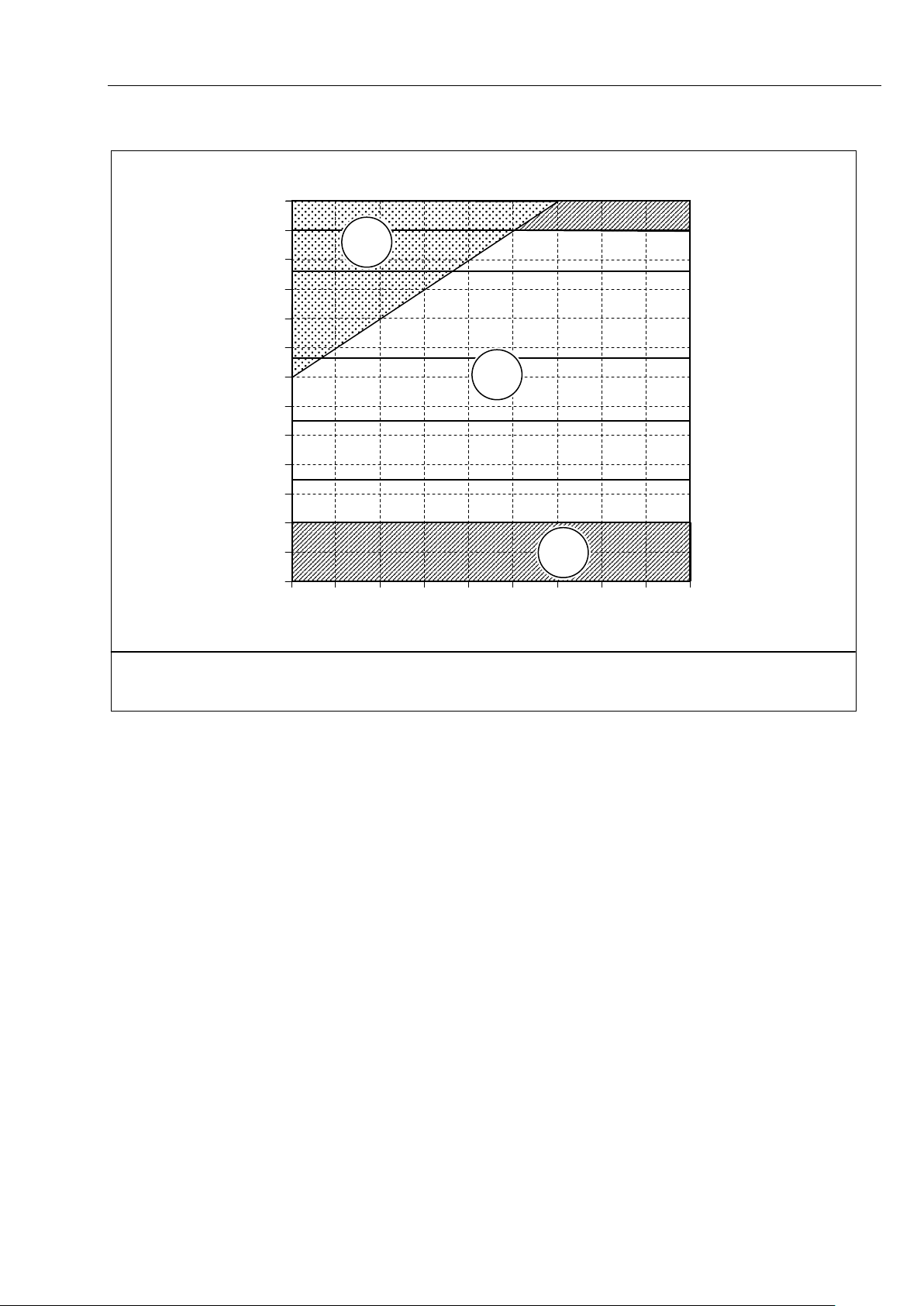
The sensor is designed wit h a pore structure suitable for trace humidity applications. A single sens or element covers th e dew-point range f rom +20 °C
DT to -80 °C DT at d ut y tem peratures of up to 60 °C. Moisture c ondens atio n
does not impair the sens or; once dr y it can be used again without having to
be recalibrated, i.e. it c an be used without difficulty in most processes subject to temporary condensation.
HYGROPHIL® F 5673 Operating manual, Software version 1.8.x, 387896MDHEN(14.06.2013)
Page 25
System description
30
Dew-point temperature DT [°C]
Gas temperature TT [°C]
-30 -20 -10 0 10 20 30 40 50 60
Sensor L 166x, Dew-point measuring range
20000
10000
1000
100
10
1
1
2
PPMV (at 1013 hPa)
3
1-19
20
10
0
-10
-20
-30
-40
-50
-60
-70
-80
-100
Out of calibrated range
-90
Calibratable range
Function range extrapolated
HYGROPHIL® F 5673 Operating manual, Software version 1.8.x, 387896MDHEN(14.06.2013)
Page 26
System description
Designation
Type
Specification
Order No.
Evaluation unit
AC 100...240 V Class1/Div.2
1 channel pre-installed
AC 100...240 V Class1/Div.1 in EEx-d casing
1 channel pre-installed
DC 10...36 V Class1/Div.2
1 channel pre-installed
DC 10...36 V Class1/Div. 1 in EEx-d casing
1 channel pre-installed
Accessories for evaluation unit
5673-110
Plug-in interface
281686
5673-114
Channel extension
287836
5673-115
Relay board
289079
5673-107
Wall mount / mounting plate
246120
Humidity sensor with integrated Pt 100
Diameter of measuring tube 10 mm, 100 bar, 200 bar against test certificate, calibrated from – 80...+ 20 °C DT
Immersion depth 36 mm
287782
Immersion depth 100 mm
281278
Immersion depth 225 mm
302470
Immersion depth 225 mm RT (for retraction tool)
302471
Special calibration in natural gas (with DAP cali0° C DT, at 41 bar)
Special calibration in hexane (freely selectable
measurement range)
Special calibration in several gases and liquids
(freely selectable measurement range)
Immersion depth 36 mm
353632
Immersion depth 100 mm
353633
Immersion depth 225 mm
353634
Protection cap with Teflon filter 10 µm
304746
Combined fibre-optic cable
Including ST plugs, 2 o ptic al fibres + 6 C u leads f or Pt 100 and press ure sens or, shielded, prot ected and fla m eretardant according to IEC 332-3A, suitable for field application, temperature range from -20°C to 70°C
Length 2 m
242445
Length 5 m
247283
Length 10 m
245449
Length 20 m
240821
Length 100 m
239954
Special lengths in 5 m steps up to 100 m
wards, max. length: 800 m
Combined fibre-optic cable with extended temperature range
Including ST plugs, 2 optical fibres + 6 Cu leads for Pt 100 and pressure sensor,
uitable for field application, temperature range
from -55°C to 70°C
1-20
1.5 Spare parts, accessories
5673-10
5673-11
5673-12
5673-13
L 1661
Series B
bration certificate, calibrated from –20° C, -10° C,
284492
242057
246119
242056
232340
232165
239 022
L 1661 LI
Series B
1631-112
Special lengths in 10 m steps, from 100 m up-
shielded, protected a nd flame-retardant according to IEC 332-3A, s
1631-113
Special lengths in steps of 5 m, up to 100 m
Special lengths in steps of 10 m, from a length of
100 m (Max. length 200 m)
for measuring
in liquids
XXXXXX
HYGROPHIL® F 5673 Operating manual, Software version 1.8.x, 387896MDHEN(14.06.2013)
Page 27
System description
Designation
Type
Specification
Order No.
Accessories
Sampler
(Swagelok-T)
5672-111
For analysis line with 6 mm
221715
5672-112
For analysis line with 10 mm
221717
ZM-WA-025040-EST
ZM-BB-007015-EST
ZM-CF-037025-EST
ZM-CF-037025-ST
ZM-CF-073025-EST
Stainless steel
(NACE)
ZM-CF-073025-ST
ZM-CF-357025-EST
ZM-CF-357025-ST
1 hook wrench
1 O-ring for PB Compac PN 250 Ø 41 x 3.5
316 SS/ up to 170 bar / ATEX, CENELEC EEx-d/e
opt. roof, 316SS
247595
274206
Sample cell „GasLiquid-separator“
Stainless steel case
IP 65 (3-parts)
Test equipment
Moisture generator
DPG-59
Approx. 20ppm / 50ppm / 100ppm
239 611
1-21
Sensor retraction tool
Blind plug
CF welding socket
for sensor retraction
tool
Compac blind flange
Mounting kit ZM-WZ-003
Sample system for
natural gas applica-
5985-13
tions
5672-129 287907
PB Compac flange PN 200, stainless steel
For sensor retraction tool, stainless steel 246711
246703
Stainless steel (NACE) 246706
Steel (NACE) 246707
Assembling small pipe diameters
(DN50, DN65, DN80)
Steel (NACE) 344860
344861
Stainless steel 246708
Steel 246720
4 screws for PB Compac PN 250
IIC T5 heated, with pressure reducer
opt. self standing support frame, 316SS
246721
279426
5673-112
283933
HYGROPHIL® F 5673 Operating manual, Software version 1.8.x, 387896MDHEN(14.06.2013)
Page 28

System description
1-22
HYGROPHIL® F 5673 Operating manual, Software version 1.8.x, 387896MDHEN(14.06.2013)
Page 29
2 Safety precautions
The evaluation units are produced in line with the regulations currently in
force and have left the factory in perf ect condition after having undergone
thorough safety tests.
● Installation and mainte nance of the evaluation units to be c arried out by
qualified staff.
● Make sure that the data an d operating conditions s pecified by BARTECBENKE are observed.
● Study the operating instructions before installing and starting up the
system. If you have any questions concerning any particular aspects,
contact our customer service for expert advice.
®
● The HYGROPHIL
essential therefore to protect it from knocks and jolts during
transportation and to select a point of installation unaffected by
vibrations.
● Instruct your operating and maintenance personnel thoroughly and
provide them with all essential information.
F 5673 is an optical precision instrument. It is
Safety precautions
2-1
● The system's internal error messages are no replacement for safety
devices in the larger facility in which the evaluation system is integrated.
● It is imperative to obs erve all the regulat ions which govern th e operation
of your facility.
● Before connecting the po wer suppl y, make sure that the eval uation unit's
operating voltage (see the type plate) matches the actual supply voltage.
● In the event of trouble, make a note of all the error messages in the
display and check whether they can be remedied. If local repair is not
possible, send the unit for repair to BARTEC-BENKE and include full
details of the fault.
● Take the unit out of operation immediately and secure it against being
started up again acc identally if there is a ny reason for supposing that it
can no longer be used safely (e.g. visible signs of damage).
Do not open the casing of the evaluation unit!
All works requiring t he evaluation unit to be opened are reser ved strictly for
qualified technical staff.
● Keep the moisture-sensitive layer of the sensor free of contamination
from oil and grease.
● Use the supplied guard caps to protect the open light waveguide
connectors on the evaluation unit and the sensor during
transportation and storage.
● Take care not to kink the light waveguides and not to bend them to a
bending radius of less than 20 mm.
HYGROPHIL® F 5673 Operating manual, Software version 1.8.x, 387896MDHEN(14.06.2013)
Page 30

Safety precautions
2-2
Instructions for the safe usage of the device
● The humidity measur ement sensor is installed in the partition wall of the
zone which in accordance to the definitions of device group II requires
category 1 equipment (zone 0).
● For the application as category 1 equipment, the am bient conditions of
the humidity measur ement sensor have to comply with t he atmospheric
conditions in accordanc e with EN 50284 (tem perature range from –20°C
to +60°C, absolute pressure range from 0,8 bar to 1,1 bar).
The humidity measurement sensor can also be applied as category 2
equipment in zone 1 at an ambient temperature Ta or a medium
temperature TM ranging from –30°C to +60°C.
● If the device is installed in systems with the risk of overvoltag e, carr y out
measures in accordance with EN 60079-14, para. 12.3 ! (also see DIN
VDE 0185)
● Humidity measurem ent sensors of the types L166x in volve the risk of an
electromagnetic charging of the plastic casing! Only use a moistened
cloth to clean the casing!
®
● The intrinsically safe circuits of the HYGROPHIL
separated up to Vm = AC 253 V (also see EN 60079-14, para. 12.3).
F are galvanically
● If the device is installed in pressure lines or pressure vess els, make sur e
the appropriate specifications (pressure vessel regulation DruckbehV,
TRG, GasHL-VO, TRGL, ...) are complied with!
● The humidity measur ement sensor has to be inc luded in the respective
tightness and pressure tests.
● Usually an adapter with a screw thread is applied between the doubleferrule swage fitting of the humidity measur ement sensor and th e facility.
On the facility side at least 5 threads of this adapter must be operative.
● Mounting the double-ferrule swage fitting:
- First rotate the nut fing ertight. If necessary tighten t he nut by using a
spanner until the measurement tube will not turn by hand.
- Mark the nut in the 6 o´clock position.
- While holding the fitting body steady with a spanner tighten the nut
with a second spann er one and on e-quarter tur ns to the 9 o´clock position (see also section 3.3.3).
● Only use BARTEC-fibre-optic cables.
● Make sure the cable of the intrinsically safe PT100 circuit and of the
intrinsicall y safe press ure transm itter circ uits are correctl y laid. Do not la y
the cables together with power supply cables in joint cable channels.
Make sure there is a s uf f ic ient dista nc e f r om electromagnetic inter f erence
fields! To prevent an y potential equalisatio n currents, tie the port of the
shielding to GND at only one place.
● In the construction of the h umidity measurement sens or , epoxy resins are
used. They are usually resistant to the mediums mentioned in the
resistance list (see table p. 2-3). In case of application as category 1
equipment in other mediums, the resistance has to be checked
separately.
HYGROPHIL® F 5673 Operating manual, Software version 1.8.x, 387896MDHEN(14.06.2013)
Page 31

Safety precautions
List of resistance for application of category-1-equipment
Alkohole
alcohols, generally
Ammoniak NH3
ammonia
Argon
Äthanol
ethyl alcohol
Chlor
chlorine
Distickstoff-Monoxid
Druckluft
compressed air
Erdgas
natural Gas
Ester
ester
Flüssigkeiten
liquids, generally
Flußsäure H
hydrofluoric acid
Helium
Hexan
hexane
Kerosin
kerosens
Kohlendioxid CO2
carbondioxide
Kohlenmonoxid CO
carbonmon¬oxide
Kohlenwasserstoffe
hydro carbons, generally
Krypton
Lachgas
Nitrous oxide
Methan
methane
Methanol
methyl alcohol
Methylenchlorid
Naphtha
naphtha
Narkosegas
narcotic gas
Neon
Propan
propane
Raffineriegas
refinery gas
Sauerstoff
oxygen
Schwefelhexafluorid SF6
Schwefelwasserstoff
hydrosulphide
SF4 Silikonöl Dämpfe
Silicon vapours
Stickoxid
nitric oxide
Stickstoff
nitrogen
Toluol
Vinylacetat
Wasserstoff
hydrogen
Xenon
Xylol
Exclusion of liability
2-3
BARTEC-BENKE GmbH and its agents shall be liable only for damage
caused by gross neg ligenc e or int ent. Said liabilit y sh all be l im ited to the value of the order in question issued to BARTEC-BENKE Gm bH .
In particular, BARTEC-B ENKE accepts no liability for damage resulting from
non-observance of the safety information or from non-compliance with the
operating instructions or operating conditions.
Liability for consequential damage is excluded.
HYGROPHIL® F 5673 Operating manual, Software version 1.8.x, 387896MDHEN(14.06.2013)
Page 32

Safety precautions
2-4
HYGROPHIL® F 5673 Operating manual, Software version 1.8.x, 387896MDHEN(14.06.2013)
Page 33
3 Installation
Ferrite noise filter
3.1 General
● Before installing the evaluation unit, make sure that your supply voltage is
the same as that set on the evaluation unit (AC 100…240 V or DC
10…36 V).
● If you want to use the output signals from the analog output and relay
outputs to control an y processes, signalin g devices or the lik e, install the
necessary wiring
● Remove the guard caps f rom the tip of the sensor, the light waveguide
connectors and the ports on the back of the evaluation unit.
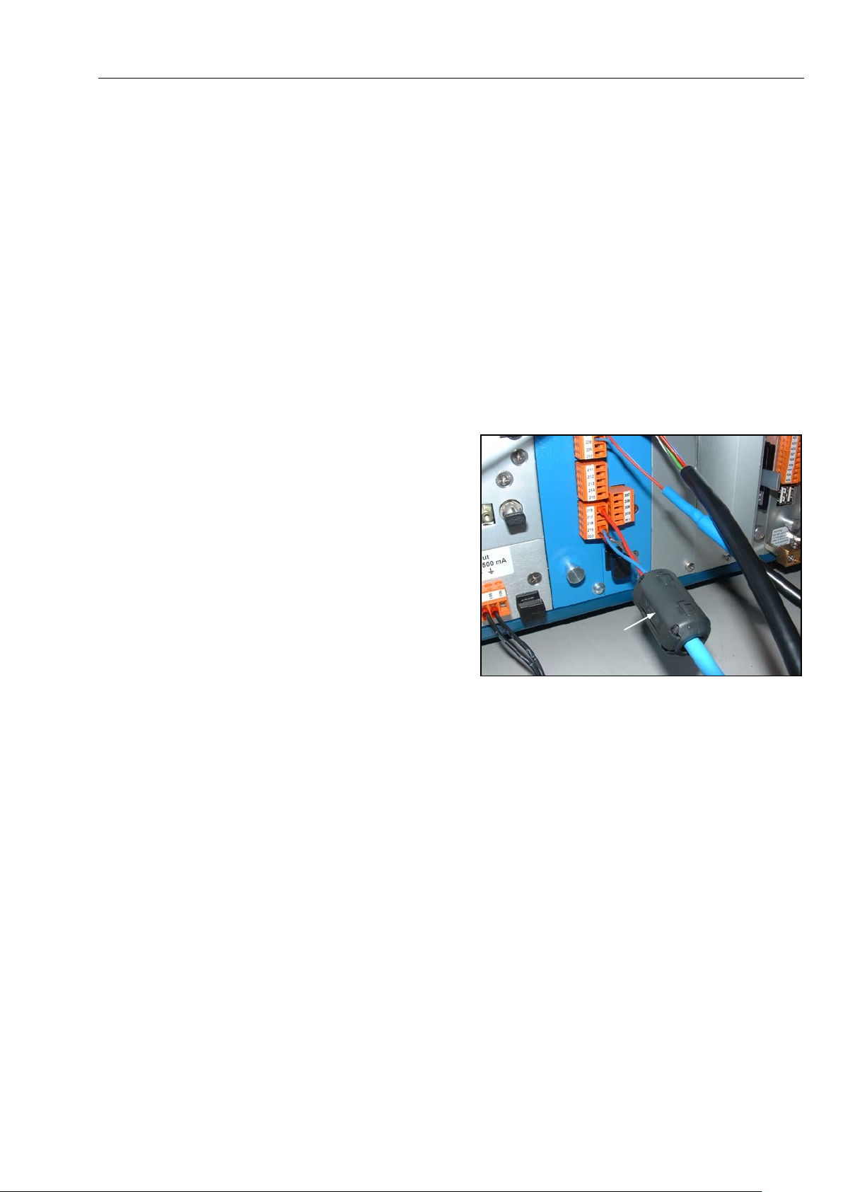
3.2 Arrangements for EMC
Ferrite noise filters
must be fixed to the
cables according to the
specifications in the
technical data of the
plug in units.
After locking the plug
contacts the filters may
no more shift.
Included in deliver y are 5 ferrite noise filters. If you need some more, you
can order them (order no. 275368).
You can also order other types for different diameters of cables.
Installation
3-1
HYGROPHIL® F 5673 Operating manual, Software version 1.8.x, 387896MDHEN(14.06.2013)
Page 34
Installation
3-2
3.3 Sensor L166x
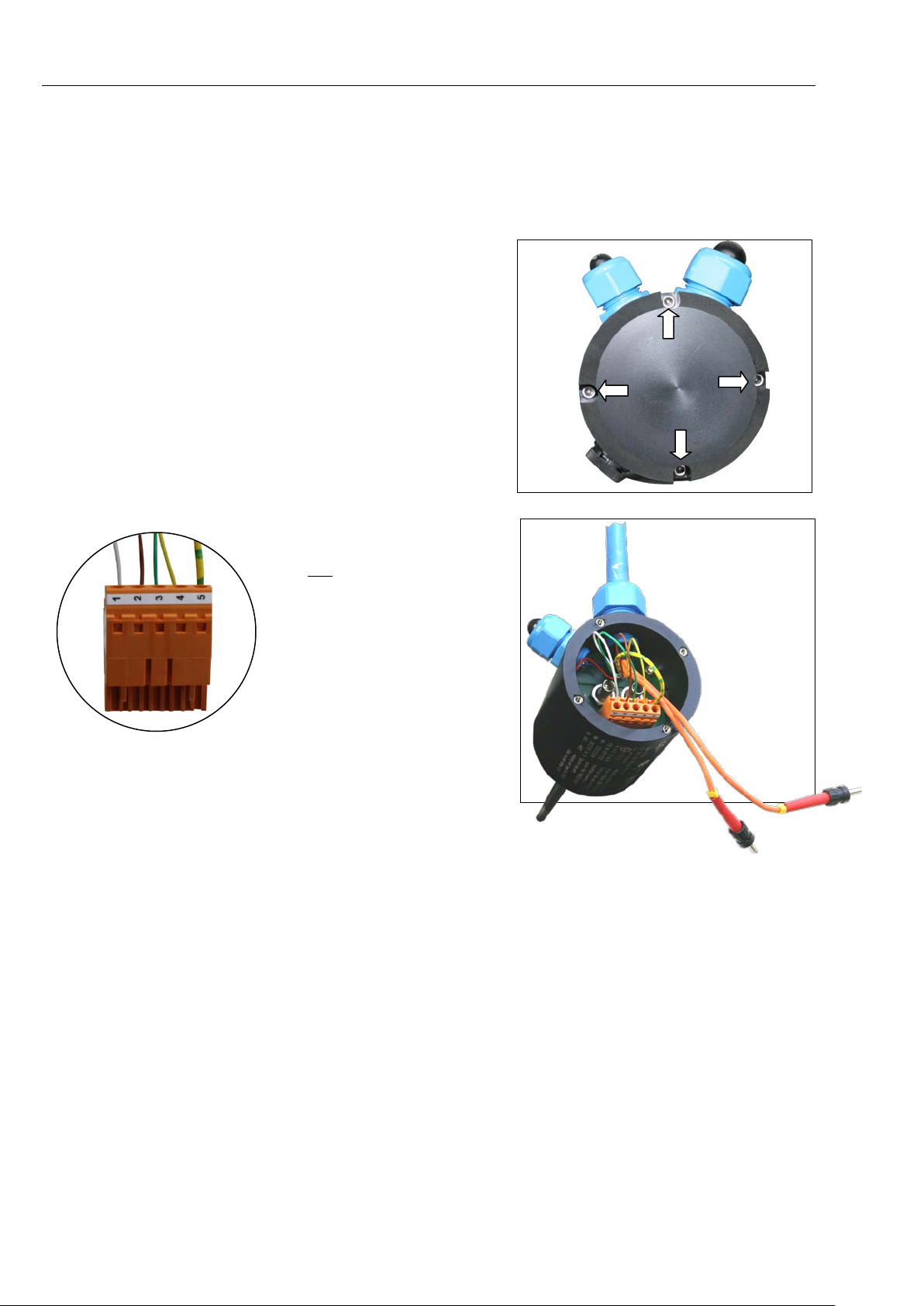
3.3.1 Wiring the sensor L166x
● Remove the 4 screws and
open the casing.
● Connect the Pt 100 cable
first.
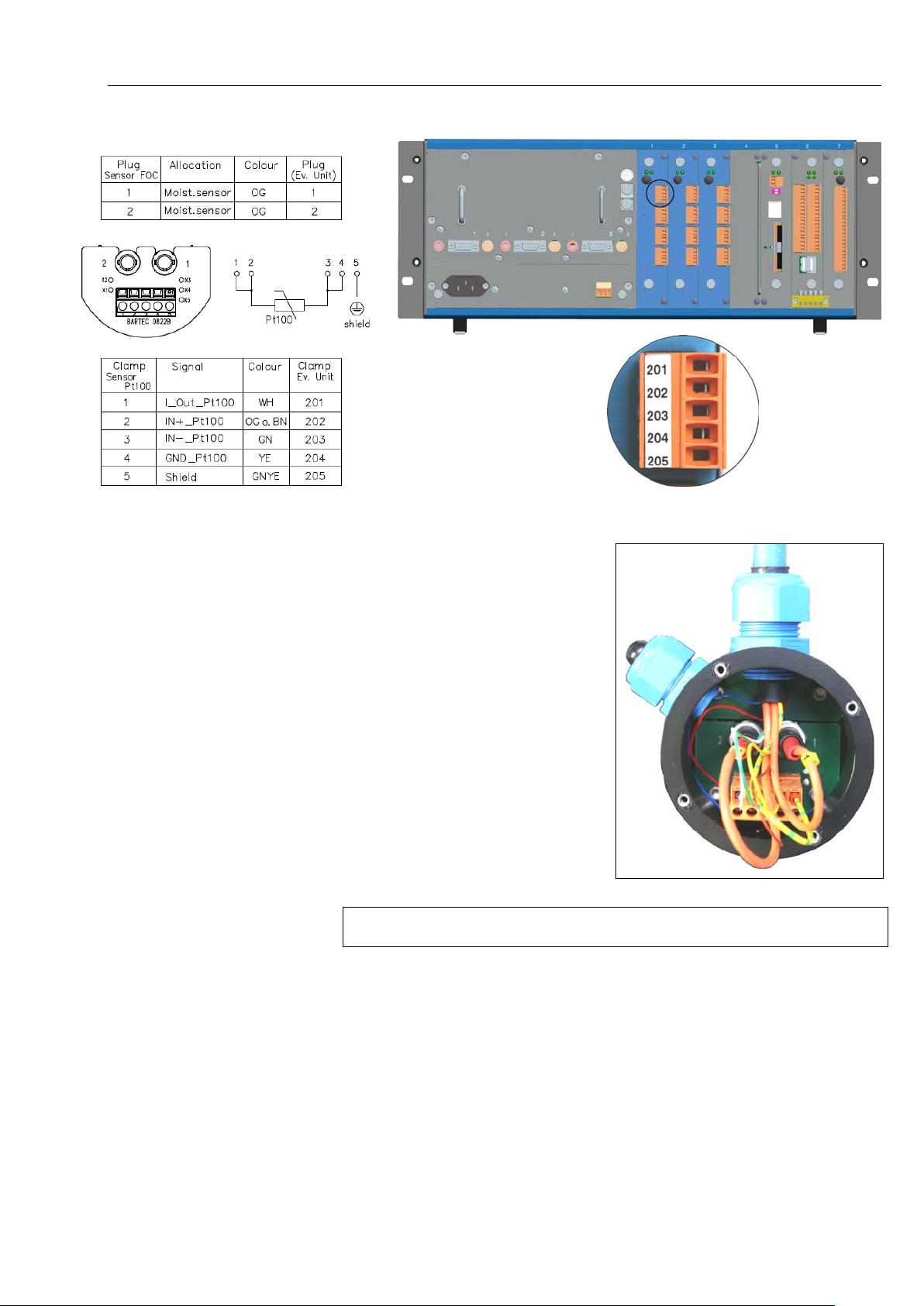
Connect the term inals 1 to 5
in the sensor casing to the
terminals 201 to 205 at the
back of the evaluation unit
(see fig. at following page).
HYGROPHIL® F 5673 Operating manual, Software version 1.8.x, 387896MDHEN(14.06.2013)
Page 35
Installation
3-3
● Connect the fibre optic cable
(bayonet connectors).
The numbers 1 and 2 on the
fibre optic cable have to ta ll y wit h
the numbers 1 and 2 at the
connections in the casing.
Let the cables m ake a ben d fr om
the entry to the ST coupling!
To protect the surfac e of the ST adapt ers remove the guard caps only directly before connecting!
● Tighten the union nuts. Pay attention to a good sealing by the rubber
plugs.
● Close the casing and fix it by the 4 screws.
HYGROPHIL® F 5673 Operating manual, Software version 1.8.x, 387896MDHEN(14.06.2013)
Page 36
Installation
3-4
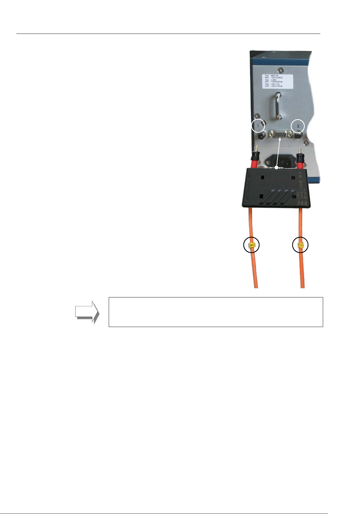
● Connect the two ST- connectors wich
are at the other e nds of the fibre opt ic
cable to the connector plug at t he back
of the evaluation unit (bayonet
connectors).
● Connect the connector plug of the
humidity sensor in the corresponding
port.
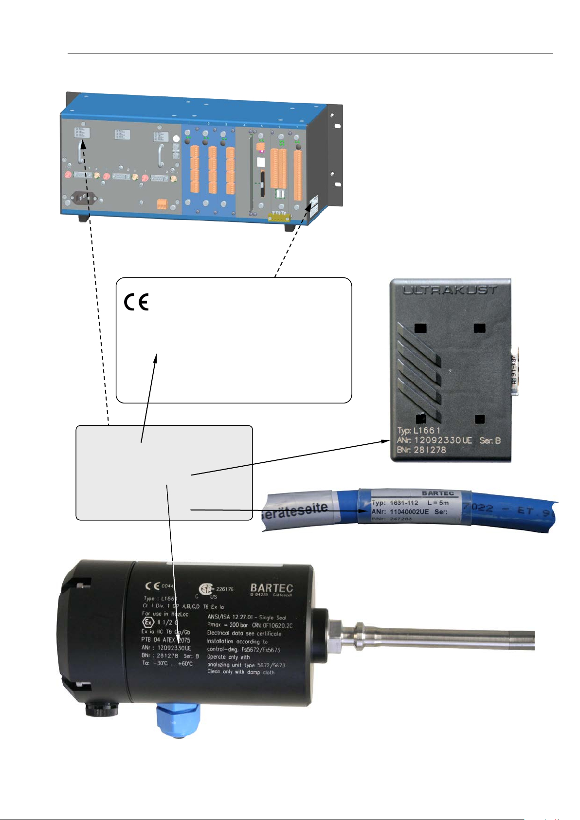
The “A” numbers of the sensors, the con nector plugs, the fibre-optic waveguide cables and the e va lu atio n u nit ha ve t o tal l y with the c or res po ndi ng “A”numbers on the system plate of the evaluation unit ( see the illustration next
page).
HYGROPHIL® F 5673 Operating manual, Software version 1.8.x, 387896MDHEN(14.06.2013)
Page 37
BARTEC
D-94239 Got t eszel l
Typ: 5673-10
ANr: 11040002UE
Type plate (evaluation unit)
System plate (evaluation unit)
0044
Typ: 5673-10
ANr: 13021605UE Serie: A
BNr: 284492
Ta: +5 °C…+50 °C
Electrical rating see power supply module
Installation
3-5
ANr: 13021605UE
Typ: L1661
ANr: 12092330UE
Typ: 1631-112
HYGROPHIL® F 5673 Operating manual, Software version 1.8.x, 387896MDHEN(14.06.2013)
Page 38
Installation
3-6
3.3.2 Installing the sensor L166x
3.3.2.1 Installing accessories
The following accessories are available for installing the sensor:
● Sampler type
● Sampler
● Gas- / Liquid-separator (SCS) type: 5985-00-003
● Retraction tool t
: 5672-111 (6 mm) (union-T) (SCS)
type: 5672-11 2 (10 mm)
ype: 5672-115
3.3.2.2 Assembly examples
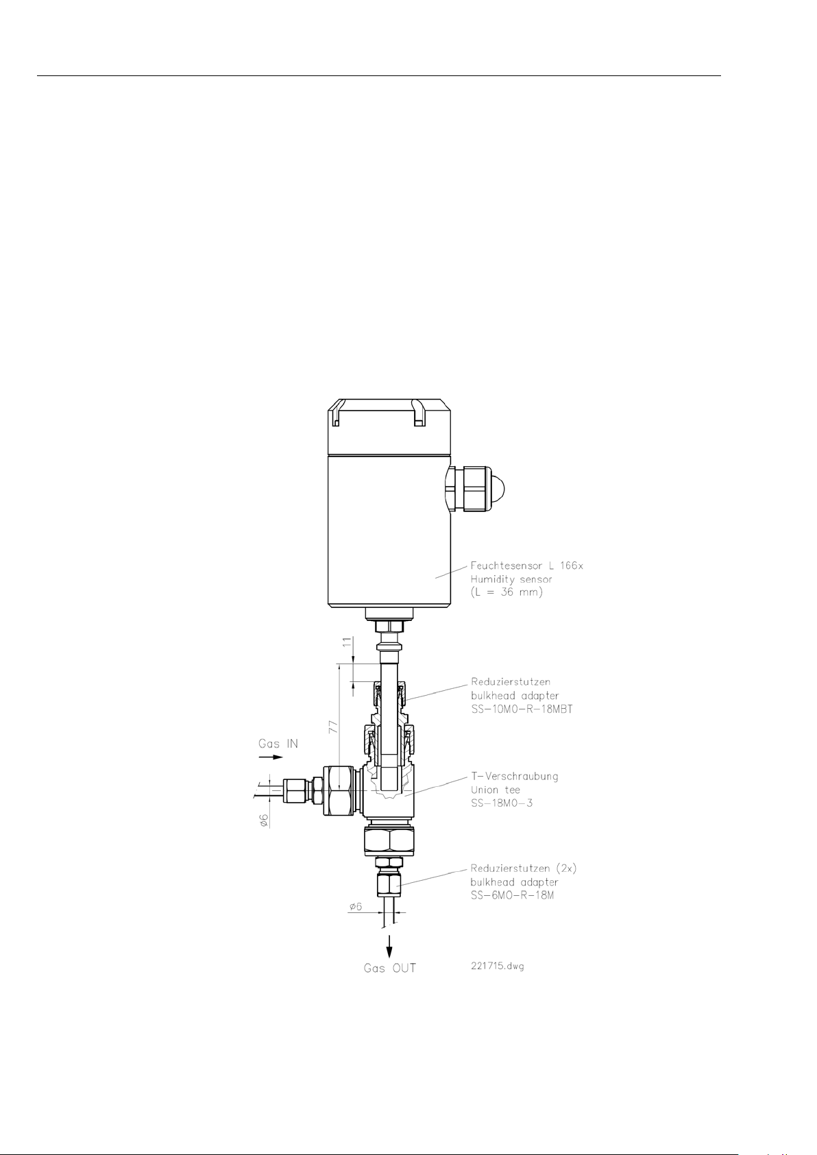
Installation in an analysis pipe via sampler
Type: 5672-111 (6 mm) (union-T), dimensions in mm
HYGROPHIL® F 5673 Operating manual, Software version 1.8.x, 387896MDHEN(14.06.2013)
Page 39
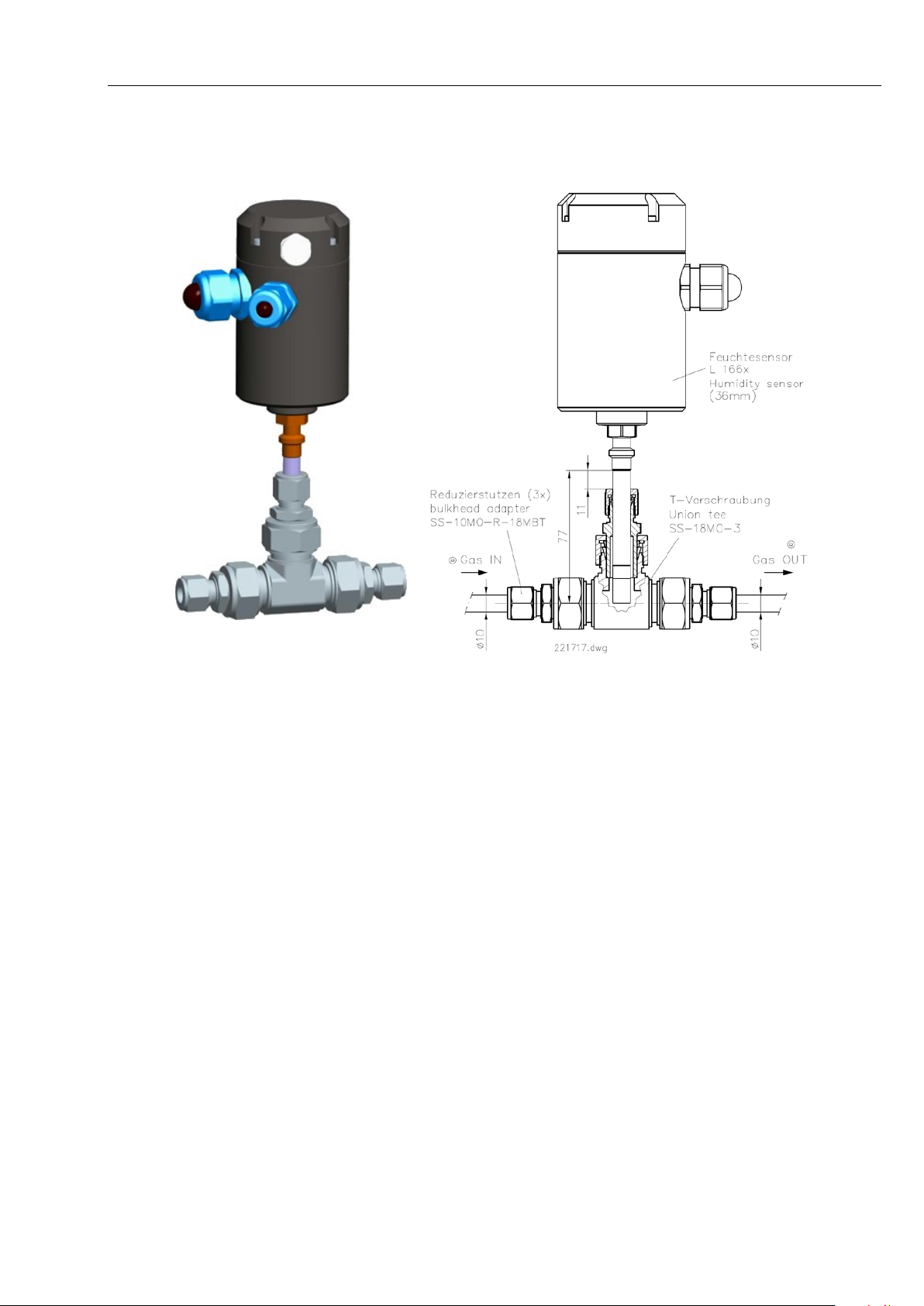
Installation in an analysis pipe via sampler
Type: 5672-112 (10 mm) , dimensions in mm
Installation
3-7
HYGROPHIL® F 5673 Operating manual, Software version 1.8.x, 387896MDHEN(14.06.2013)
Page 40
Installation
3-8
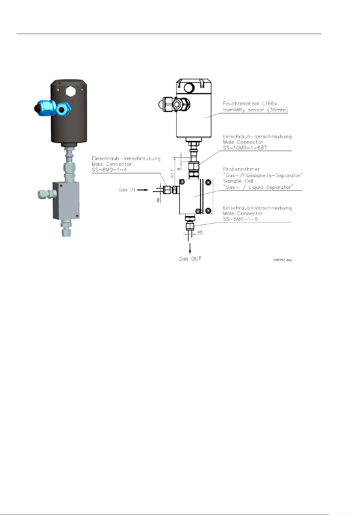
Installation in an analysis pipe via Sample cell „Gas- Liquid-separator“
Type
: 5985-00-003 , dimensions in mm
HYGROPHIL® F 5673 Operating manual, Software version 1.8.x, 387896MDHEN(14.06.2013)
Page 41
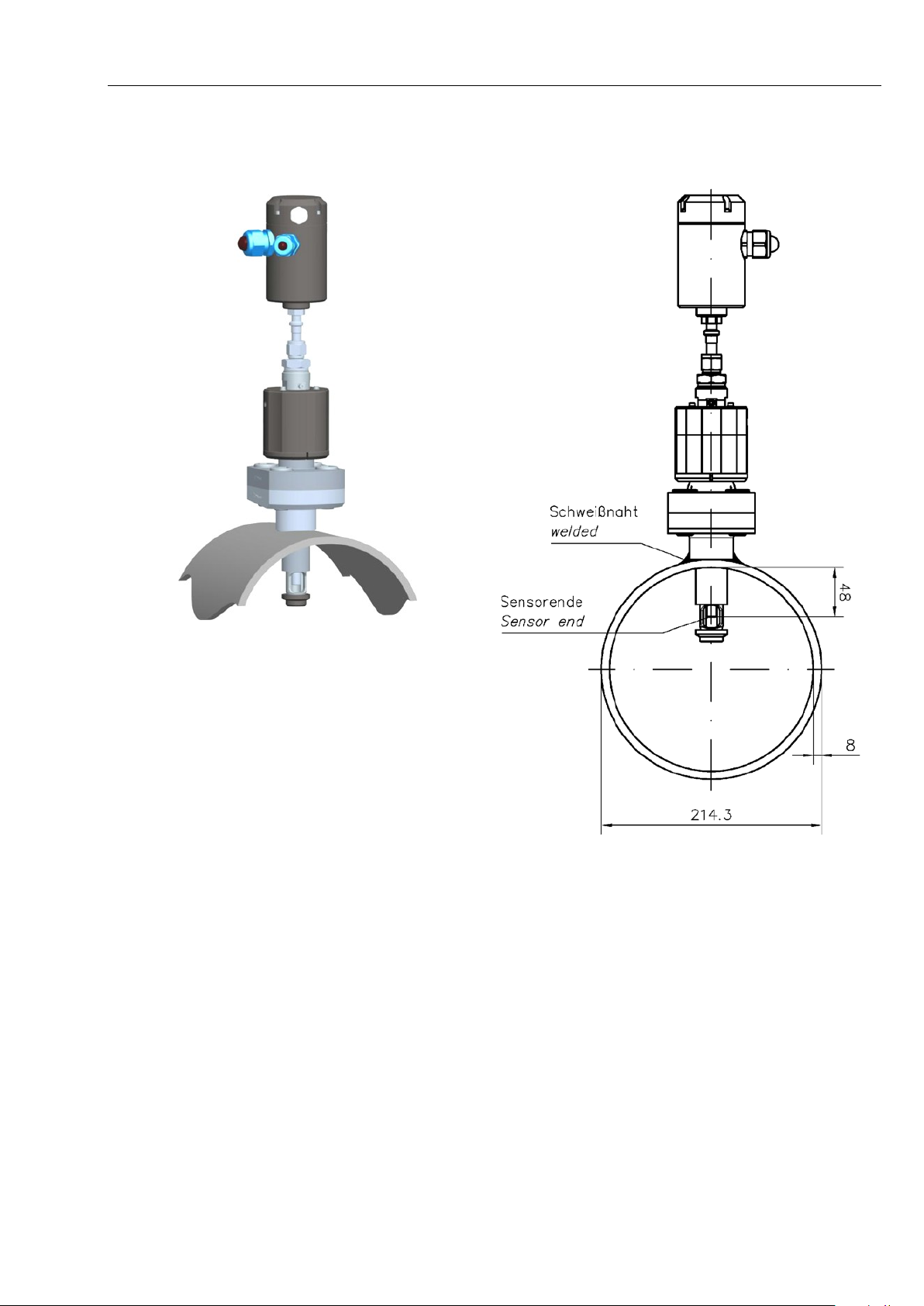
Installation in a mains pipe or bypass pipe via retraction tool
Type: ZM-WA-025-040, dimensions in mm
Installation
3-9
With the retraction to ol will be delivered an instruction manual that includes
all information of m ounting, operation and ser vice of the tool in com bination
with the sensor L 166x.
HYGROPHIL® F 5673 Operating manual, Software version 1.8.x, 387896MDHEN(14.06.2013)
Page 42
Installation
3-10
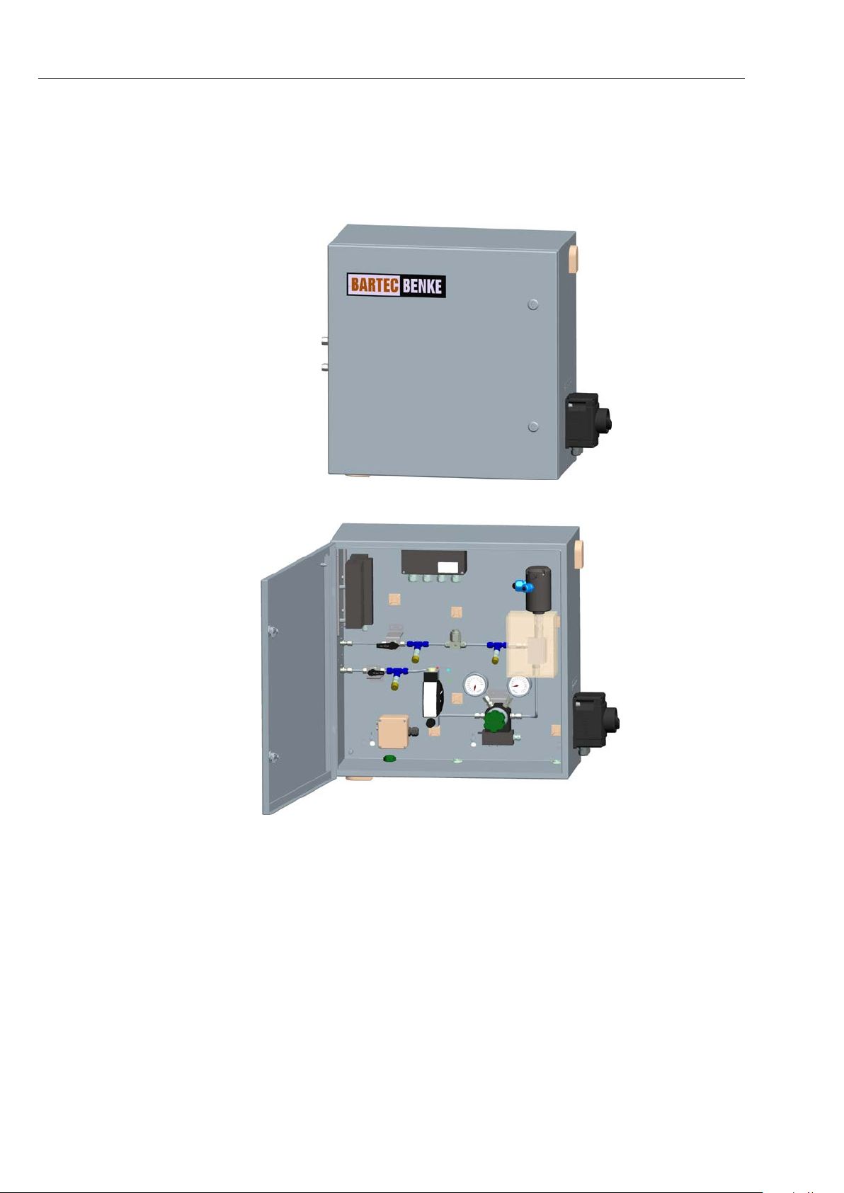
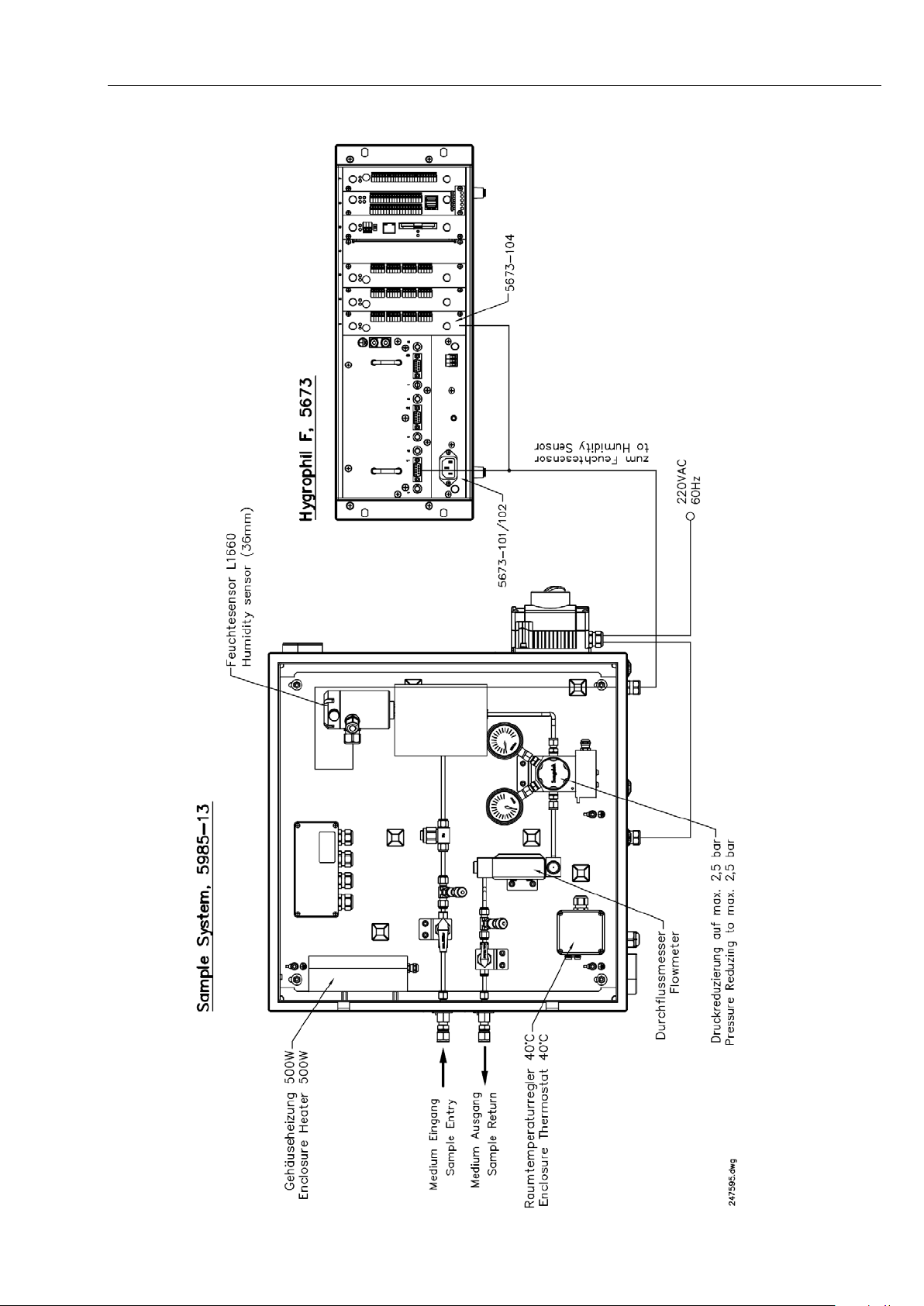
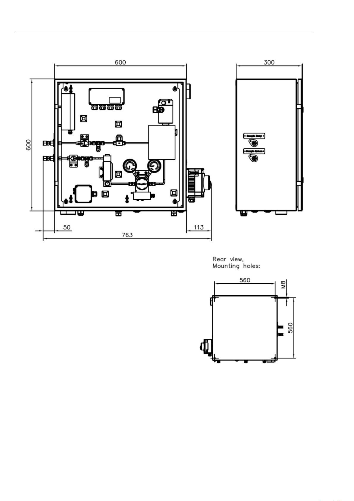
Integration in a sample system
Type 5985-13
To measure humidity in na tural gas the s ensor L 166x can be in tegra ted in a
sample system.
HYGROPHIL® F 5673 Operating manual, Software version 1.8.x, 387896MDHEN(14.06.2013)
Page 43
Installation
3-11
HYGROPHIL® F 5673 Operating manual, Software version 1.8.x, 387896MDHEN(14.06.2013)
Page 44
Installation
Dimensions in mm
3-12
HYGROPHIL® F 5673 Operating manual, Software version 1.8.x, 387896MDHEN(14.06.2013)
Page 45
3.3.3 Installation advice
50
Don´t clamp the
Dimensions in mm
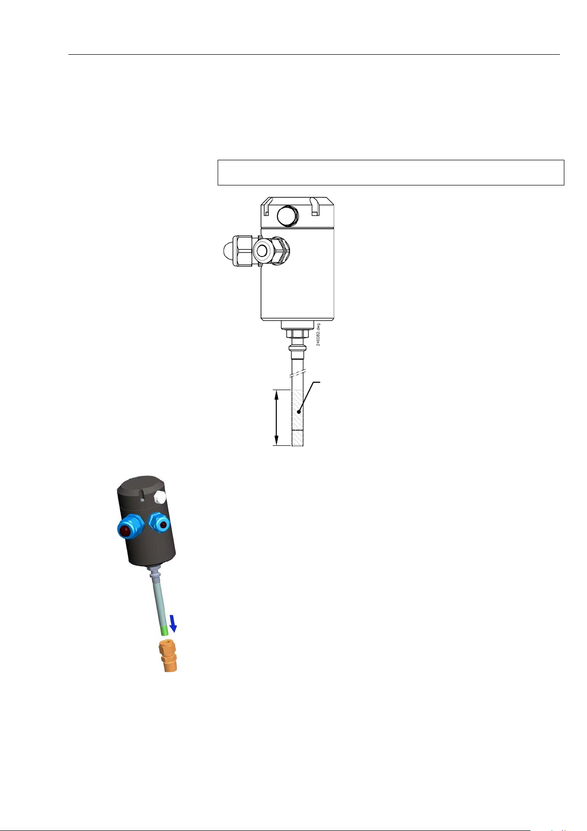
Before installing the s ens or m ake s ure that th e stainl es s steel pr otect ion c ap
is screwed tightly to the tip of the sensor.
The sensor L166x can be fitted with any suitable compression type fitting.
Never mount the ferr ules within the distance of 50 mm , measured from the
sensor tip (incl. protection cap ) !
Installation
3-13
sensor in this
area!
The following sequence de scribes the procedure to in stall the sensor in the
gas-/ liquid-separ a tor w ith Swag elok fittings.
This applies to union-T and slow down section likewise. At the retraction
tool, the nut is already mounted on the sensor.
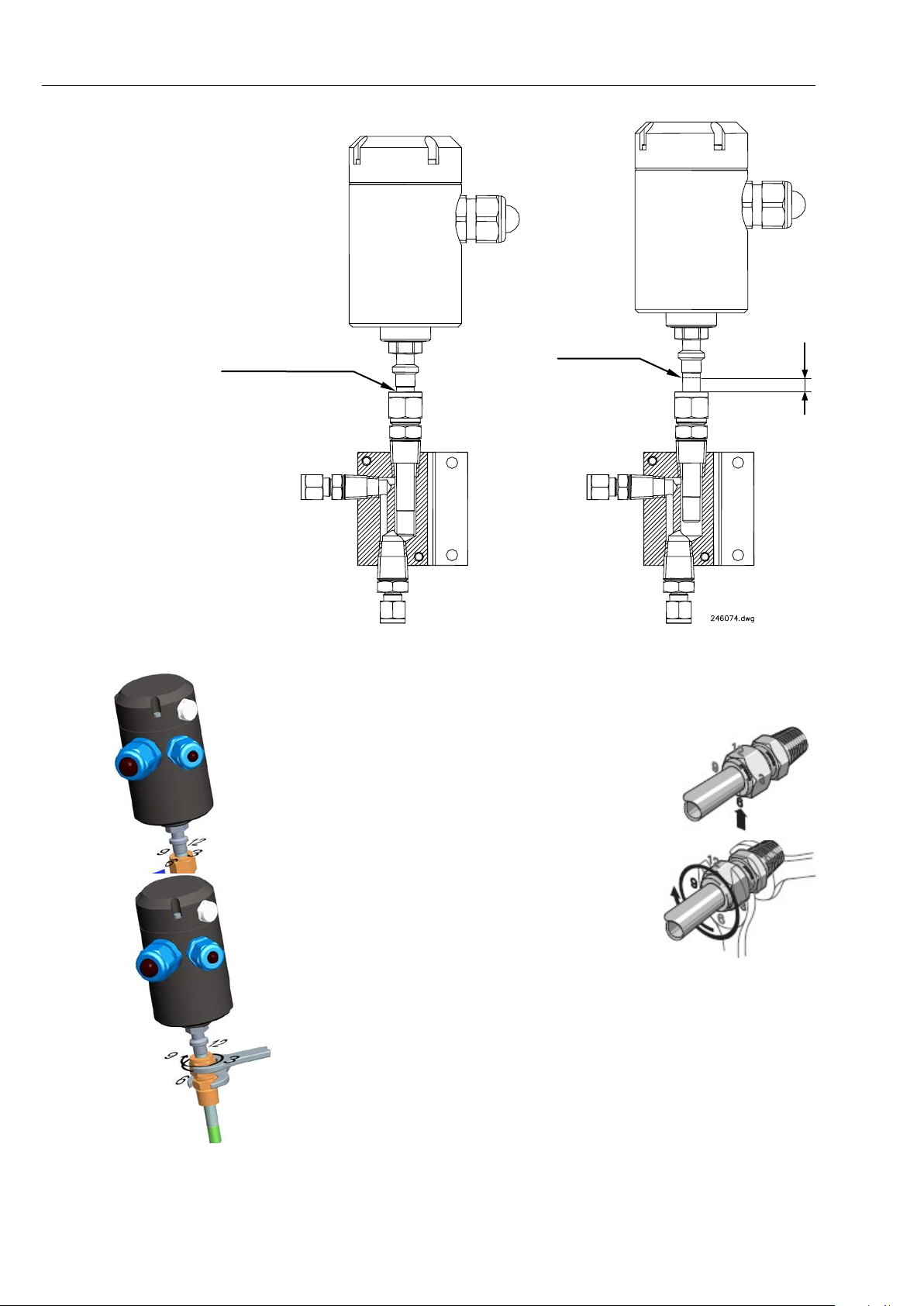
1. Assemble union nut with back and front ferrule on the connector.
Make sure that both ferrules are fitted correctly.
2. Insert the sensor in the union nut until the tip of the sensor hits the bottom of the sample cell.
3. Mark the immersion depth with a pen approx. 1 mm above the union nut.
4. Lift the sensor appr. 8...10 mm.
HYGROPHIL® F 5673 Operating manual, Software version 1.8.x, 387896MDHEN(14.06.2013)
Page 46
Installation
mark with a pen
marking
8
Dimensions in mm
3-14
5. Tight the union nut accordi ng to the procedure of the compr ession type
fitting manufacturer:
- First rotate the nut fing ertight. If necessary tighten t he nut by using a
screw-wrench until the measurement tube will
not turn by hand.
- Mark the nut in the 6 o´clock position.
- While holding the fitting body steady with a
screw-wrench tighten the nut with a second
screw-wrench one and one-quarter turns to
the 9 o´clock position.
HYGROPHIL® F 5673 Operating manual, Software version 1.8.x, 387896MDHEN(14.06.2013)
Page 47
4 Operation
4.1 Start up
The evaluation unit is not equipped with a switch. Connect the evaluation
unit to the mains by the mains cable.
After the supply voltag e has been applied, the software is init ialised. Then
the automatic sensor equalisation is carried out („Auto-Equalize“).
This process takes about one minute.
Then the measuring variables are displayed.
4.2 Automatic sensor equalizing
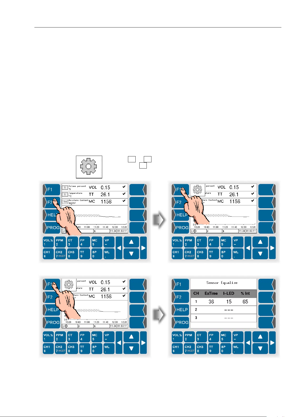
The automatic sensor equalizing as it is execut ed when the system is s tarted, will be repeated in an interval of 24 h our s, when a measuring cycle is finished.
You can trigger the sensor equalizing any time during the measuring mode.
Touch F1 or F2 key. The current functi ons of theese keys are disp layed.
Then touch F1 ke y, („A. EQUAL.“) to start the automatic sensor equalizing
function.
Operation
4-1
HYGROPHIL® F 5673 Operating manual, Software version 1.8.x, 387896MDHEN(14.06.2013)
Page 48
Operation
Combined display
(3 measurement value lines plus graphic)
Measurement value display
(6 measurement value lines)
Online graphic display
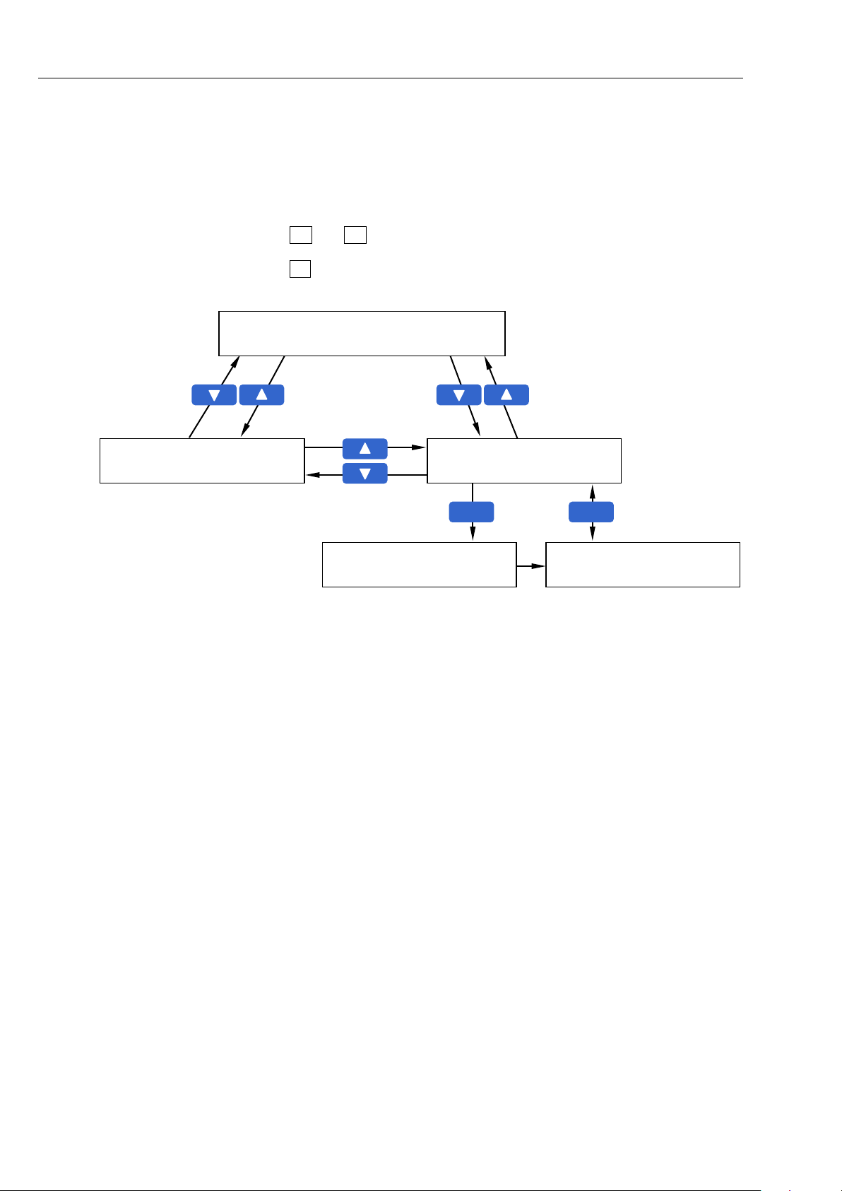
History graphic display
(see page 4-13)
F2
F1
History-Setup
(see section 4.3.5.1)
4-2
4.3 Display modes
After the automatic s ensor adjus tm ent has bee n com pleted, the u nit is r ead y
for operation.
The display can tak e place in three different on line modes and one histor y
graphic mode.
Use and to switch between the three online display modes.
Use F2 to switch between the online gr aph ic disp la y and the history graphic
display (see page 4-13).
HYGROPHIL® F 5673 Operating manual, Software version 1.8.x, 387896MDHEN(14.06.2013)
Page 49
4.3.1 Combined display
Channel number
Measurement variable
Measurement value
Status indication
Dimension
Graphics
Info line
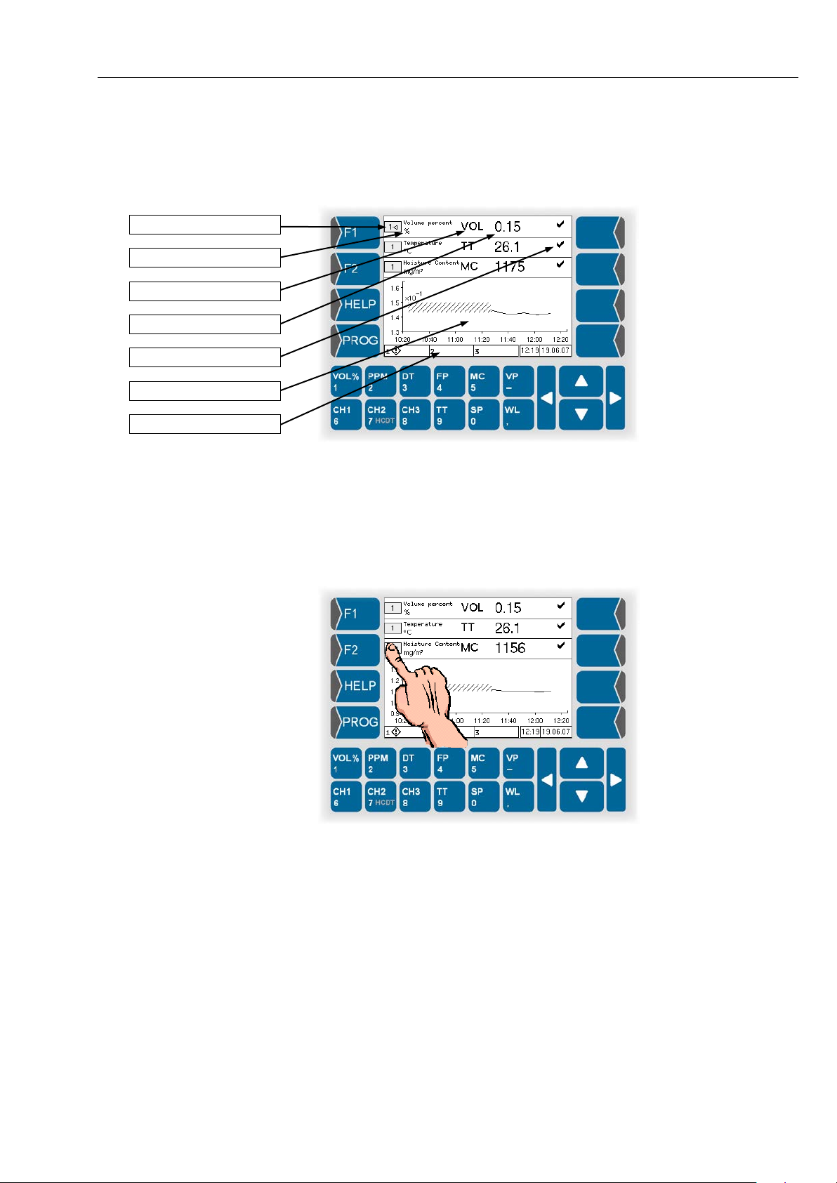
The display shows thr e e lin es wh ich c an i nd icate d if ferent measurement variables at the same time.
Operation
4-3
You can assign an avail able chan nel t o eac h lin e and s elect a m eas urem ent
variable to be displayed.
4.3.1.1 Selecting a line
Before you can set the indication of a line, you have to select this line.
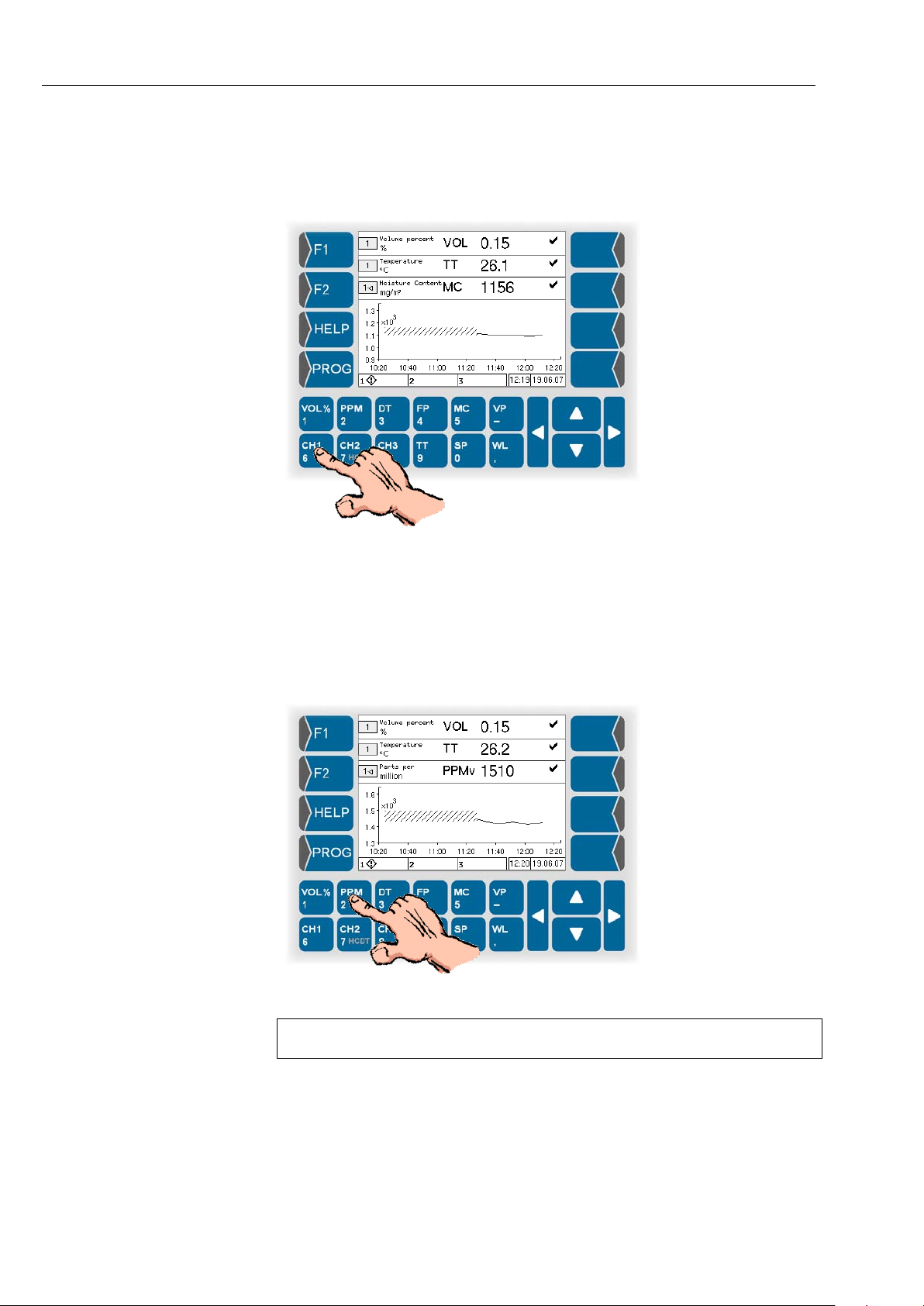
Touch the field which indicates the channel number.
When the line has been selected, it is marked by an arrowhead after the
channel number.
HYGROPHIL® F 5673 Operating manual, Software version 1.8.x, 387896MDHEN(14.06.2013)
Page 50
Operation
4-4
4.3.1.2 Assigning a channe l
In order to assign a channel to the s elected display line, touch t he key with
the appropriate channel designation (CH1, CH2 or CH3).
In the field for the channel number, the appropriate numeric character appears.
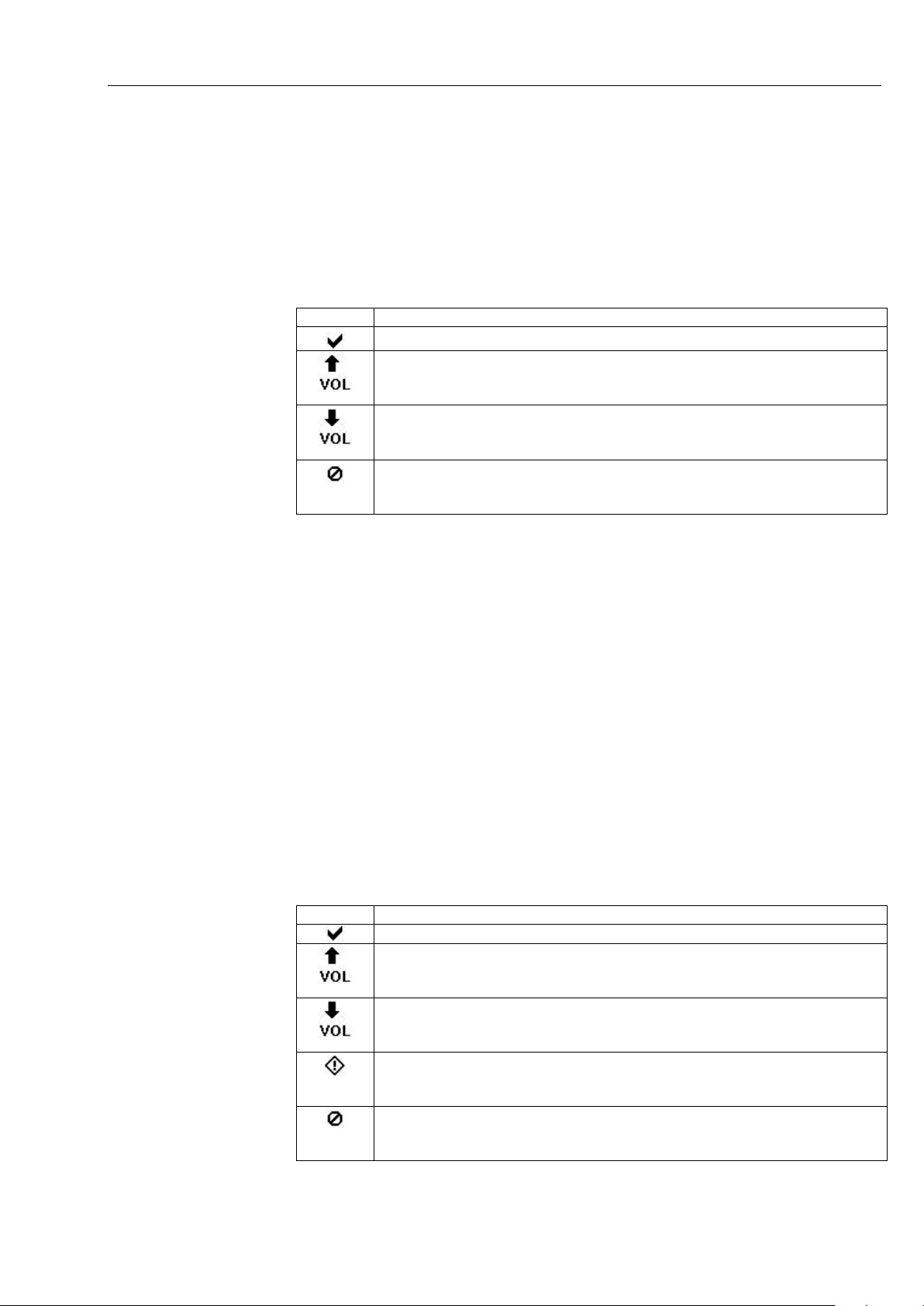
4.3.1.3 Assigning a measurement variable
In order to assign the meas urement variable to be dis played to the selected
line, touch the key with the appropriate measurement variable.
The selected measurement variable is indicated.
With the key for vapour co ntent [Vol%]
vapour content and relative humidity.
HYGROPHIL® F 5673 Operating manual, Software version 1.8.x, 387896MDHEN(14.06.2013)
, you can toggle the displ ay between
Page 51
4.3.1.4 Fixed values
Icon
Meaning
Measured values are ok
Programmed limit (see section 5.6.4) has been exceeded
exceeded (see also section 6.1).
Programmed limit (see section 5.6.4) has been fallen below.
fallen below (see also section 6.1).
Error
also section 6.3)
Icon
Meaning
Measured values are ok
Programmed limit (see section 5.6.4) has been exceeded.
exceeded.
Programmed limit (see section 5.6.4) has been fallen below.
fallen below.
Warning
measuring operation is not interrupted (see also section 6.2)
Error
also section 6.3)
If a primary measurement variable is not measured b y a sensor, the fixed
value configured f or it is d ispla yed (s ee sect ion 5.6.3). In this case, an ast erisk is displayed behind the dimension.
4.3.1.5 Status indication
In each line, the status of the measurement values is indicated by icons.
Below the icon there is the m easurement variabl e whose l imit has been
Below the icon there is the m easurement var iable whos e limit has be en
Indication of an error, measuring mode is not possible an y more (see
Operation
4-5
4.3.1.6 Graphic
Below the indication of the measurement variable there is a diagram presenting the measurement value curve of the measurement variable in the
currently activated line for the last two hours.
If you activate an other line, the graph ic for the measurem ent values of this
line is displayed. In intervals of 30 seconds, another measurement value is
displayed. Every 10 minutes a measurement value is written into the data
memory. If you switch to anot her display and then retur n to the graphic display, the recorded dat a is r ead from the data m em or y and is presented. Due
to the data recording in intervals of 10 minutes, the curve is smoothed.
For periods during whic h no measurem ent values are availab le (e.g. device
is turned off, no sensor is connected), the measurement value progress
curve is hatched.
4.3.1.7 Info line
The info line below the gra phic shows inf ormation on the op erating status of
the measuring channe l, the current working temperature range and as well
as the current date and time.
Below the icon there is the m easurement variabl e whose l imit has been
Below the icon there is the m easurement variabl e whose l imit has been
Indication of missing measurement values, fixed value is used. The
Indication of an error, measuring mode is not possible an y more (see
HYGROPHIL® F 5673 Operating manual, Software version 1.8.x, 387896MDHEN(14.06.2013)
Page 52
Operation
4-6
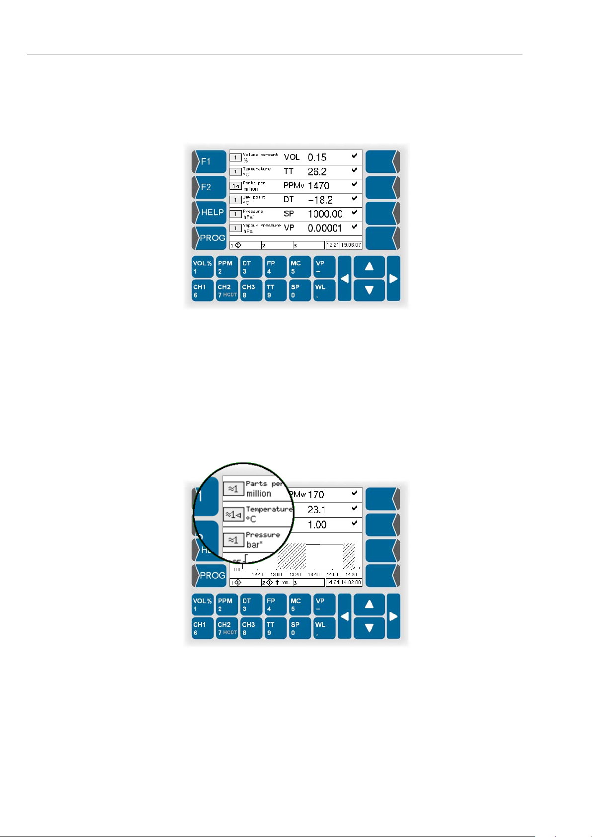
4.3.2 Measurement val ue display with six lines
In this display mode, thr ee further lines with measurem ent value indications
are shown instead of the graphic.
The setting of the displa y in the s ix meas urem ent value lin es is the sam e as
in the combined displa y modes . An y changes of the se ttings in the f irst three
lines are taken over into the mixed display mode after switching there.
The status display and the info line are th e sam e as in the com bined displa y
mode.
4.3.3 Measuring the humidity in liquids
If the humidity in liquids is m easured a double waved line is indic ated befor e
the channel number.
HYGROPHIL® F 5673 Operating manual, Software version 1.8.x, 387896MDHEN(14.06.2013)
Page 53
4.3.4 Online graphic display
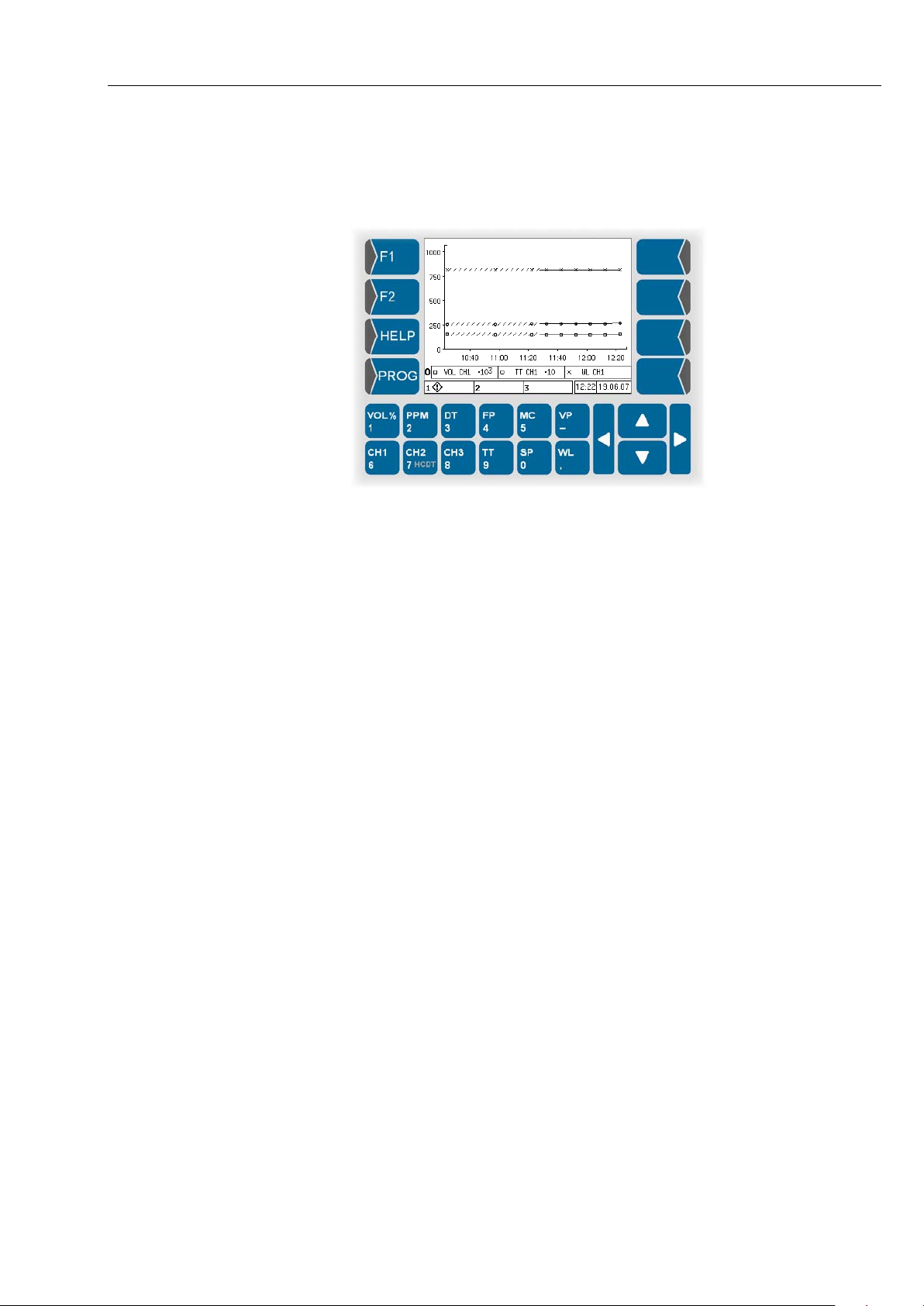
In the online graphic displ ay, the measurem ent value curve of the m easurement variables of line 1, 2 and 3 for the last 2 hours is presented.
Operation
4-7
To distinguish the curves, they are marked with different symbols (x, □, ○).
As only one scaling is us ed for the measurement value axis, t he measurement values are multiplie d by powers of ten so that they can be presented
within the value range of the measurement value scale.
In the line below the graph ic, you find some inf ormation on the three m easurement value curv es pres ente d. T he “O“ at th e beg inning of th is lin e sta nds
for “Online“ und serves to distinguish this mode from the “History graphic
mode“ („H“).
Every 30 seconds a new measurement value is presented. Every 10
minutes, a measurem ent value is written into th e data m emor y. If you switch
to another display and then r eturn to the graphic display, the rec orded data
is read from the data m emor y and is pres ented. Due to th e data recor ding in
intervals of 10 minutes, the curve is smoothed.
For periods during whic h no measurem ent values are availab le (e.g. device
is turned off, no sensor is connected), the measurement value progress
curve is hatched.
The info line is presented like in the two other online display modes.
HYGROPHIL® F 5673 Operating manual, Software version 1.8.x, 387896MDHEN(14.06.2013)
Page 54
Operation
4-8
4.3.5 History graphic display
The measurement values recorded in int ervals of 10 minutes are written into
a database with a memory capacity for 6 months.
You can define a per iod for which you want t o present the stored m easurement value progress curves for up to three measurement categories.
4.3.5.1 History Setup
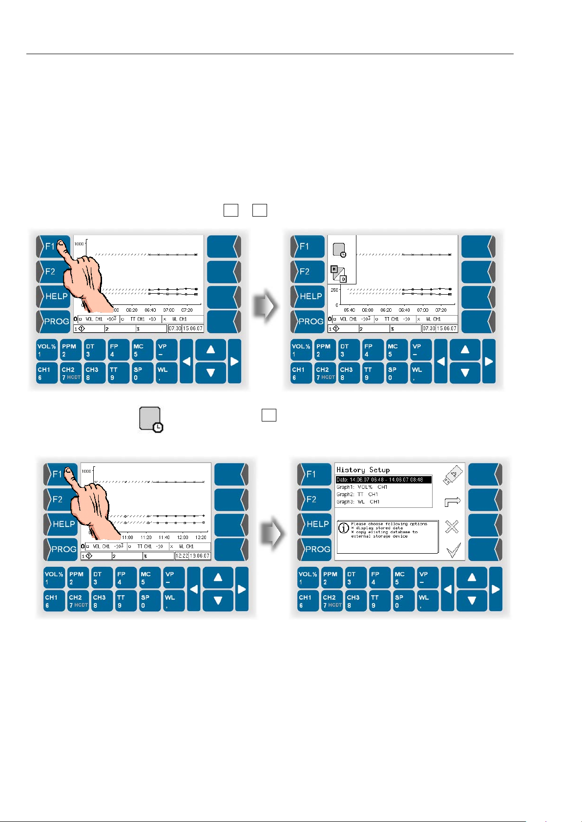
● Switch to the online graphic mode.
● Touch F1 or F2 key. The current functions of theese keys are displayed.
● Then touch the F1 key to open the History Setup.
HYGROPHIL® F 5673 Operating manual, Software version 1.8.x, 387896MDHEN(14.06.2013)
Page 55
Operation
Defining the presentation period
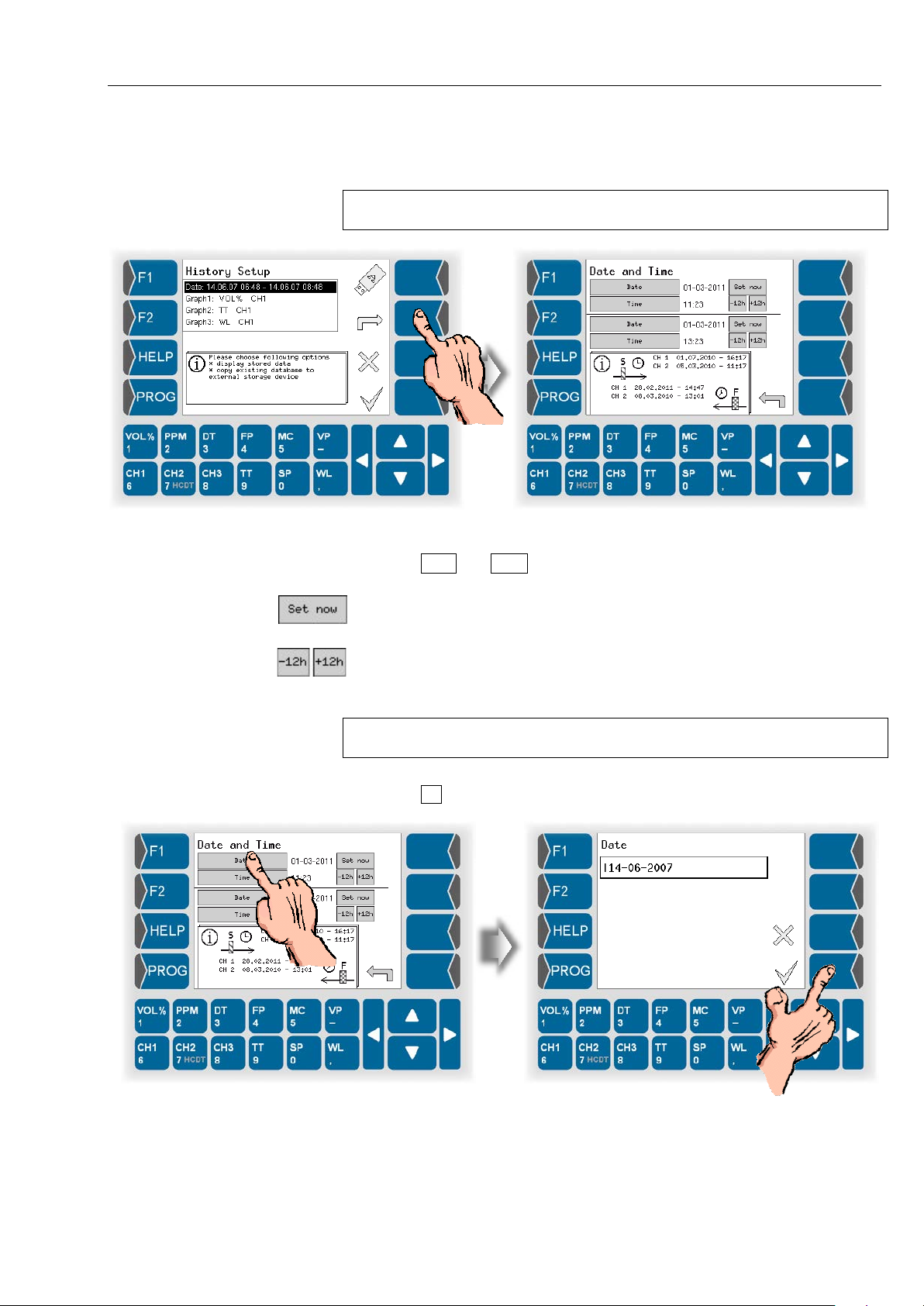
● Open the dialog for editing the presentation period.
You can see the period containing data in the database in the display.
The point in time of the first and last value for the channel is displayed.
4-9
Now you can define the presentation period.
● Touch Date and Time for the start and the end of the presentation period
and enter the required values.
Use this button to set the current time and date.
Use this buttons to change the time in 12 hour steps.
You can enter each othe time and date into the according field.
The time between the start and the end of the presen tation period has to be
at least 2 hours.
● Touch to confirm the entries.
HYGROPHIL® F 5673 Operating manual, Software version 1.8.x, 387896MDHEN(14.06.2013)
Page 56
Operation
4-10
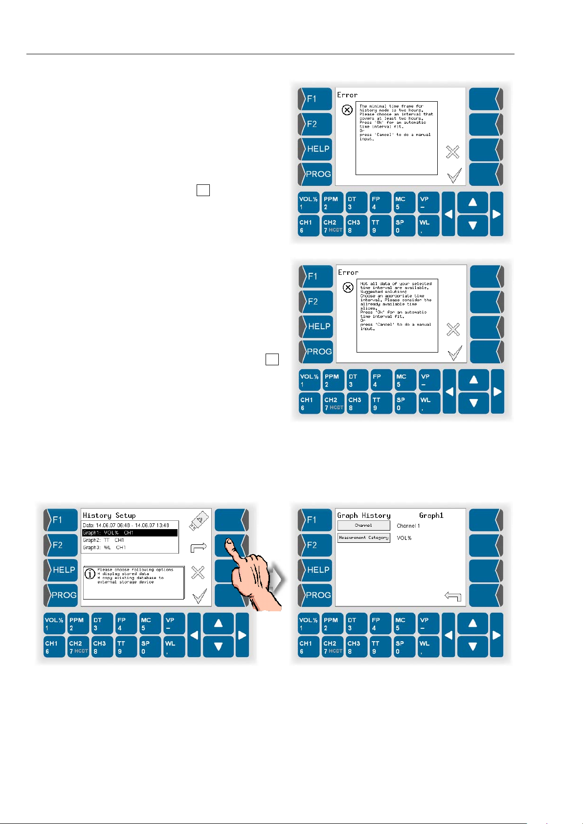
If the presentation period you have defined
is too short, a message appears when
you leave the history
setup.
If you confirm the
message by
ing , the peri od of 2
hours is automatically
selected.
If the selected presentation period includes a
period for which no data is available, the following message appears.
If you confirm the message by pressing ,
the period is automatically corrected.
Defining the presentation of the graph
● Select a line for t he graph (graph 1 in the exam ple below) and open th e
dialog for editing the graph.
HYGROPHIL® F 5673 Operating manual, Software version 1.8.x, 387896MDHEN(14.06.2013)
Page 57
Operation
4-11
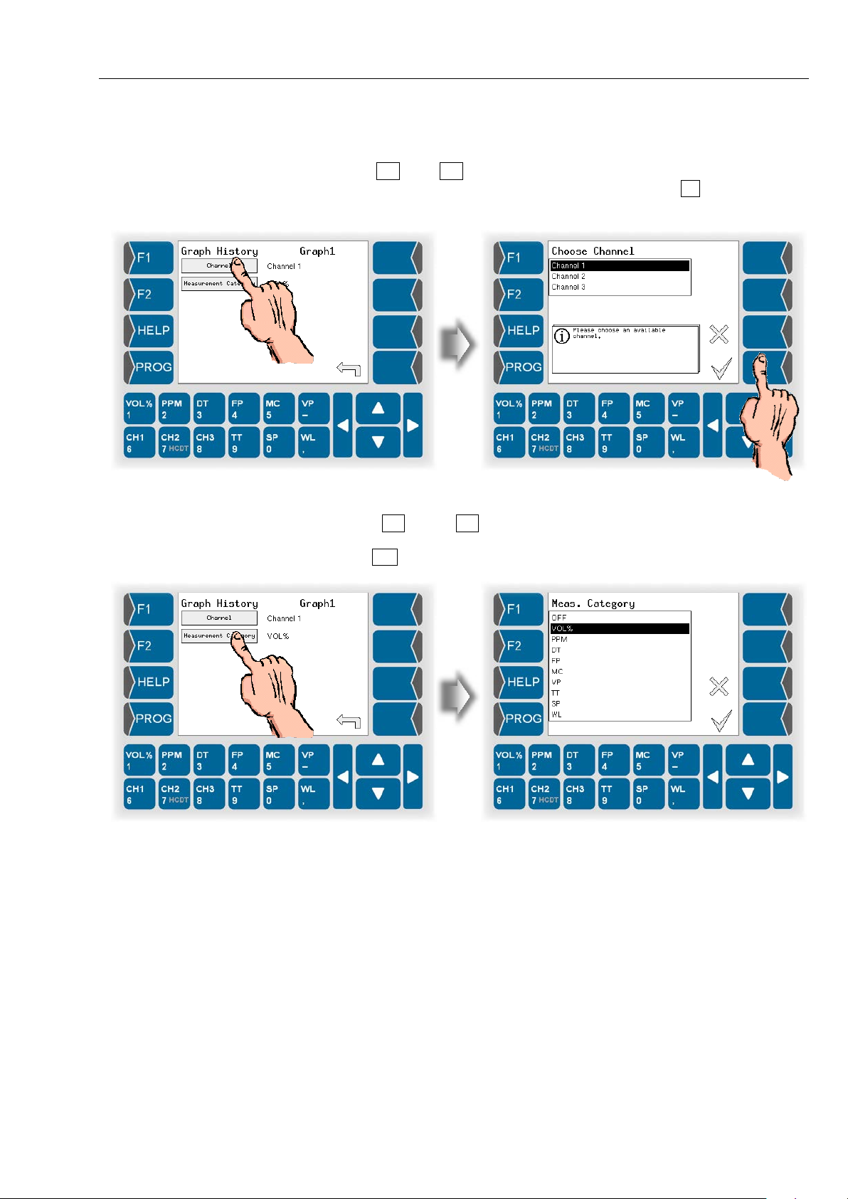
Now you can def ine the channel and the measurement variable f or the selected graph.
● Use and to select the measurement channel whose stored
measurement values shall be presented. Touch to confirm the
selection.
● Open the Measurement category selection.
● Use and to select the measurement variable whose
measurement value curve shall be defined for the defined period.
Use to confirm the selection.
In the same wa y you can define two fur ther measurement variables whose
measurement curve shall be presented for the defined period (graph 2,
graph 3).
HYGROPHIL® F 5673 Operating manual, Software version 1.8.x, 387896MDHEN(14.06.2013)
Page 58
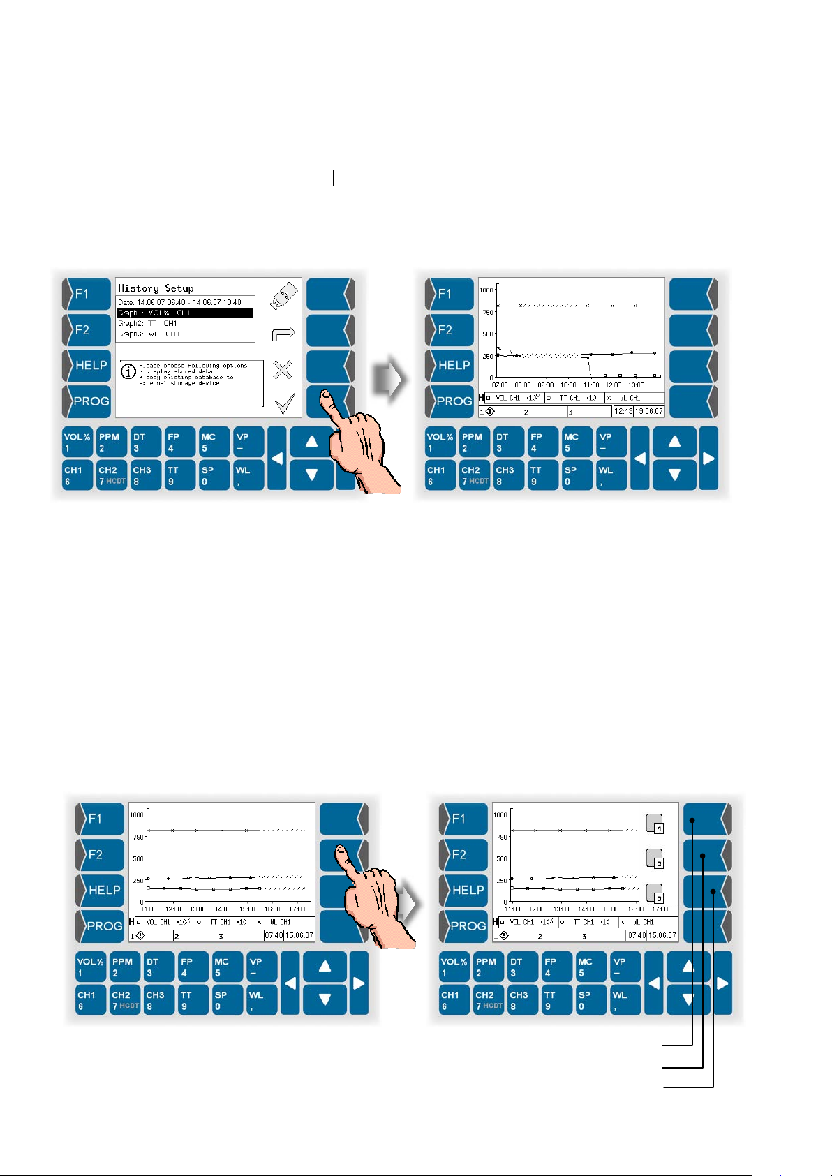
Operation
Hide / display graph 1
Hide / display graph 3
4-12
4.3.5.2 Display the history graphic
● After carrying out all required settings for the graphic history mode,
touch .
If the settings are incorrect, a message will appear (see page 4-10).
If the settings are correct, the history graphic is displayed.
Like in the online graph ic mode, the curves are mark ed with different symbols (x, □, ○). As on ly one scaling is used for the m easurement value axis,
the measurement val ues are m ultiplied b y powers of ten so that th ey can be
presented within the value range of the measurement value scale.
In the line below the grap hic, ther e is i nform ation on th e three m easurem ent
value curves present ed. The letter “H” at the begin ning of this line s tands for
„History“ and serves to d istingu ish this m ode f rom the “Online grap hic m ode”
(“O“).
Hide Graphs
By touching the three uppe r keys right of the displa y you can hide a nd recall
each of the graphs.
● Touch one of the keys right of the display. The current functions of theese
keys are displayed.
● Touch the according key to hide or to display one of the graphs.
Hide / display graph 2
HYGROPHIL® F 5673 Operating manual, Software version 1.8.x, 387896MDHEN(14.06.2013)
Page 59
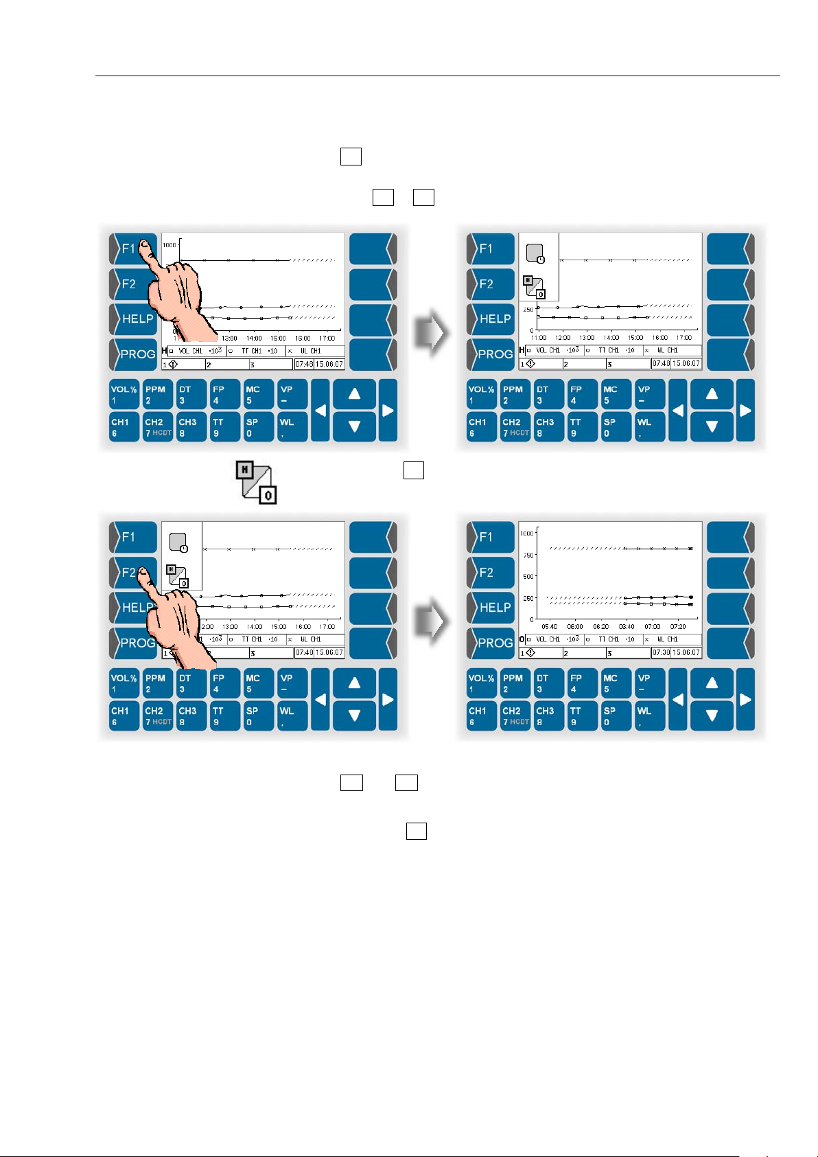
Operation
4-13
Changing the display mode
Use F2 to switch b etween the histor y graphic mode and the online graphic
mode.
● Touch F1 or F2 key. The current functions of theese keys are displayed.
● Then touch F2 key, to switch from online graphic mode to history graphic
mode or reverse.
Use and to leave the history graph ic mode and switch to an online
indication mode.
To call up the histor y grap hic m ode again, s witch t o th e on line gr aphic m ode
and then touch F2 twice.
HYGROPHIL® F 5673 Operating manual, Software version 1.8.x, 387896MDHEN(14.06.2013)
Page 60
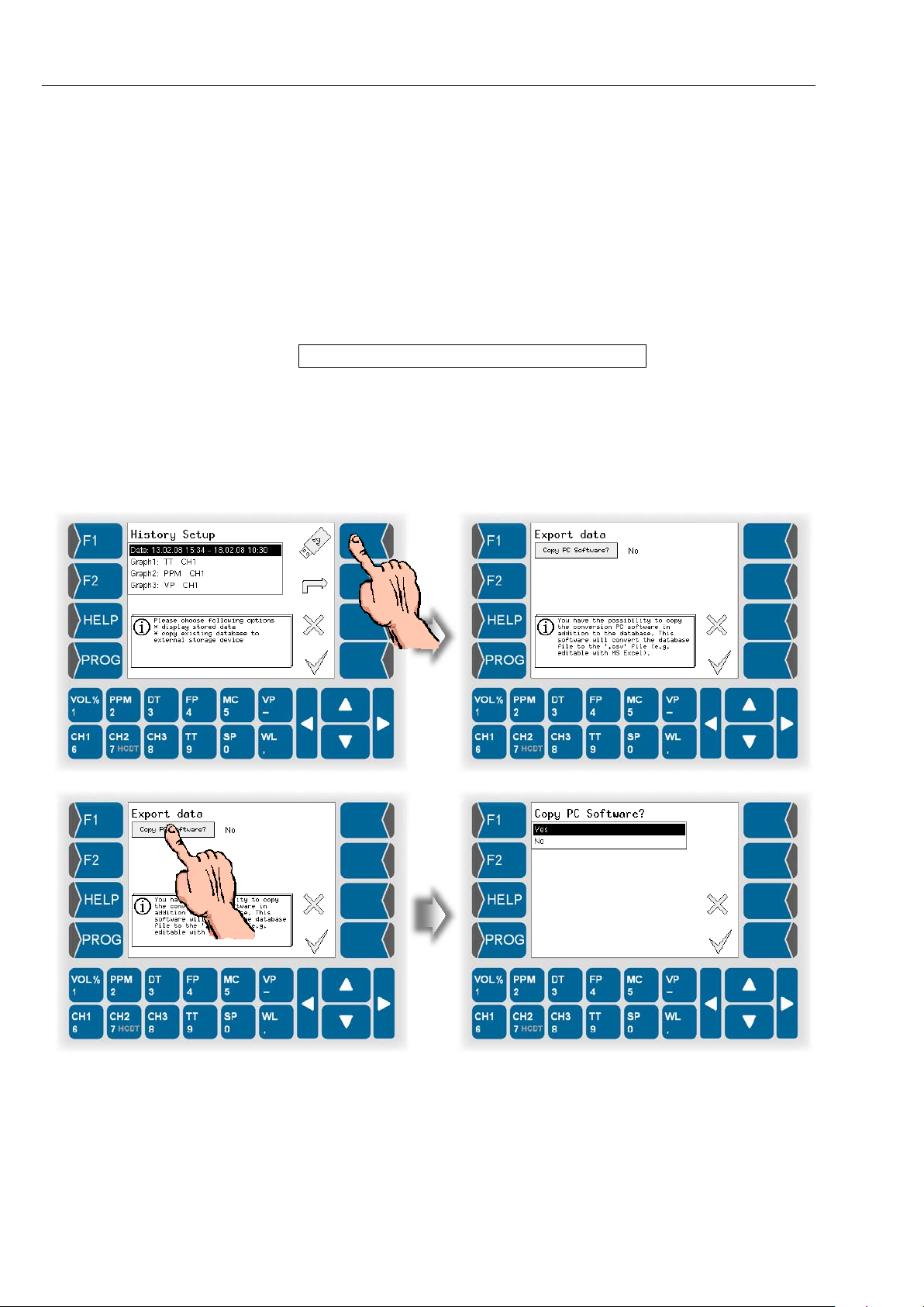
Operation
4-14
4.4 Data e xpo rt
HYGROPHIL® F 5673 safes the measuring data in a SQLite-database.
You can copy this d atabase via US B-port to an external dat a medium and if
required convert into a .csv file.
4.4.1 Copy data
● Connect the external medium (e.g. USB-stick) to the USB-port at the
back of the evaluation unit.
The data medium must be FAT 32 formatted!
● Call up Hisory-Setup (see section 4.3.5.1).
● Touch the key with the USB-stick icon.
Then you can choose t o transfer a PC software (data c onverting program)
additionally. For using the data convert ing program , you must only transf er it
once.
HYGROPHIL® F 5673 Operating manual, Software version 1.8.x, 387896MDHEN(14.06.2013)
Page 61
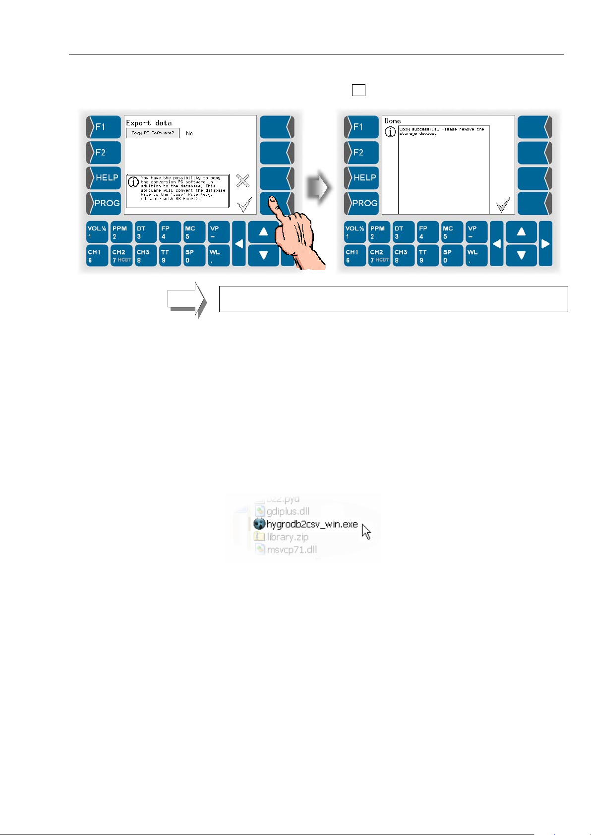
● Start data export with the key.
Operation
4-15
The database is always transferred completely. The defined presentation period for the history graphic display has no influence on the data export.
● For further process ing the data connect the data medium to your PC via
USB-Port.
4.4.2 Converting data
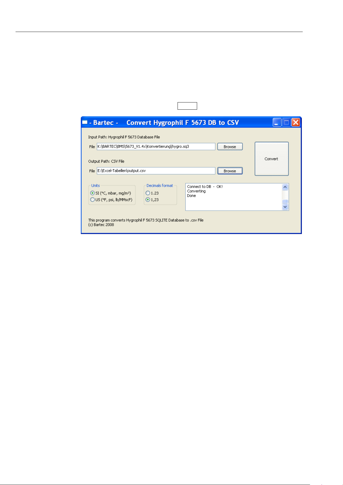
By using the PC-program that you can transfer additiona lly to the database
you can convert the databa se to a .c sv f ile. You can open a nd edit th is f ile in
Windows-applications, such as MS Excel, Open Office.
● First unpack the file hygrodb2csv_win.zip. It contains the converting
program.
● The folder hygrodb2csv_win contains the program file
hygrodb2csv_win.exe. Start this pr ogram.
HYGROPHIL® F 5673 Operating manual, Software version 1.8.x, 387896MDHEN(14.06.2013)
Page 62
Operation
4-16
● Choose in the line below „Input Path“ the file that is to conver t.
● Choose in the line b elow „Output Pa th“ the folder in which the con verted
data shall be saved. Instead of the file name „output“ you can enter a
desired file name.
● Under „Units“ select the output format of the measuring values.
● Under „Decimals format“ select the kind of decimal separator.
● Start converting with the Convert button.
4.4.3 Export servic e information to an external data medium
For an analysis by your service staff you can export service information to an
external data medium . Databases, log files and conf iguring information will
be copied to the data medium . For this purpose open the menu „System Information“ (see section 5.6.15).
HYGROPHIL® F 5673 Operating manual, Software version 1.8.x, 387896MDHEN(14.06.2013)
Page 63
5 Programming
Icon
Meaning
Effect
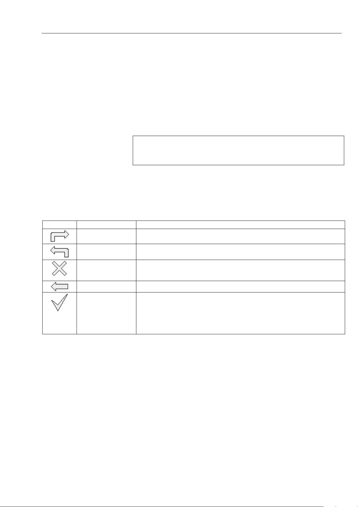
Open
The marked menu is opened,
Quit menu
You quit the m enu that is o pen at present an d change over to the sup er or-
Abort
You quit the m enu that is o pen at present an d change over to th e super orSettings/entries already carried out are rejected.
Correct
In an entry dialog the character left to the cursor is deleted.
Take over, store
The selected setting of a parameter is confirmed.
key!
Programming
5-1
Various operating param eters and funct ions can be pr ogrammed in order t o
operate the HYGROPHIL
adjust the measurem ent s ystem to the given o perat ing requirem ents and the
system environment.
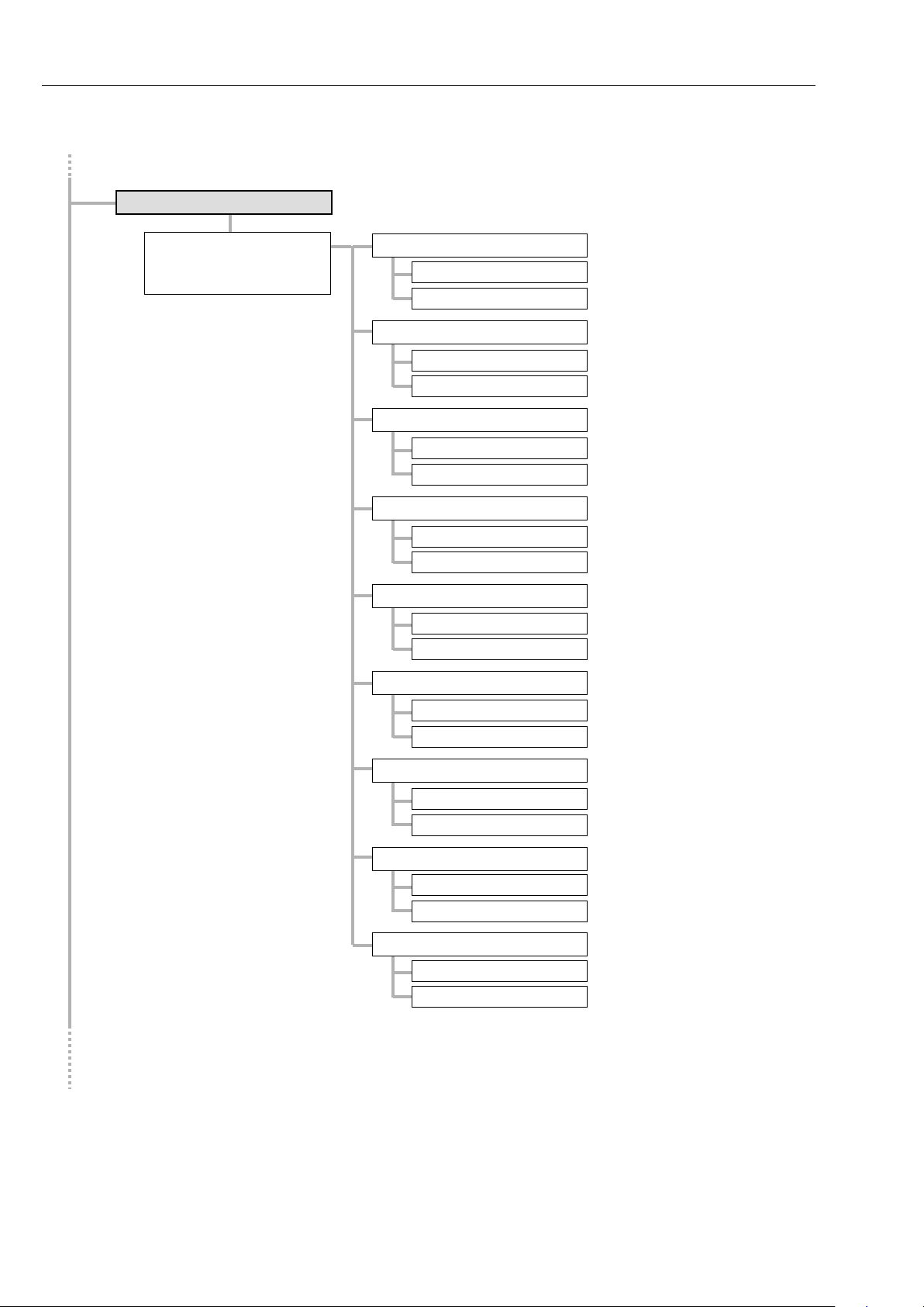
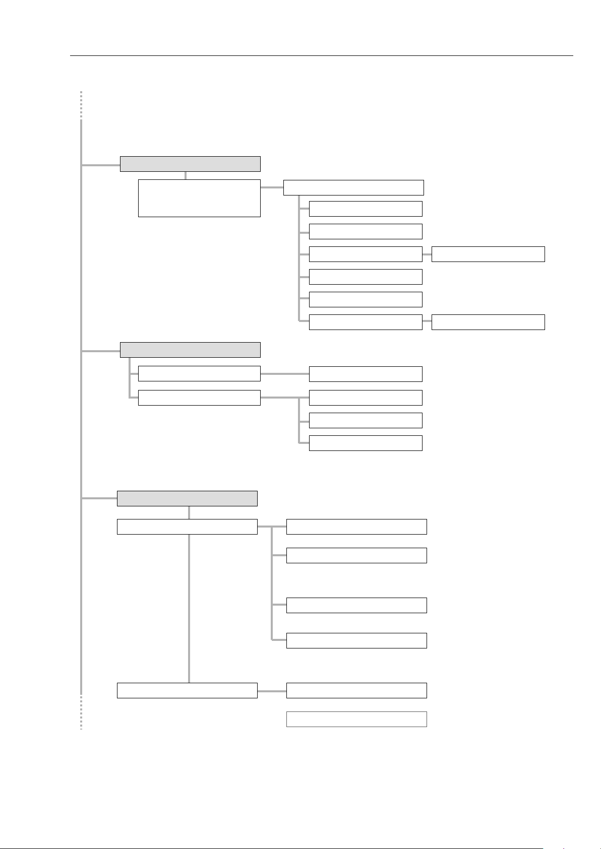
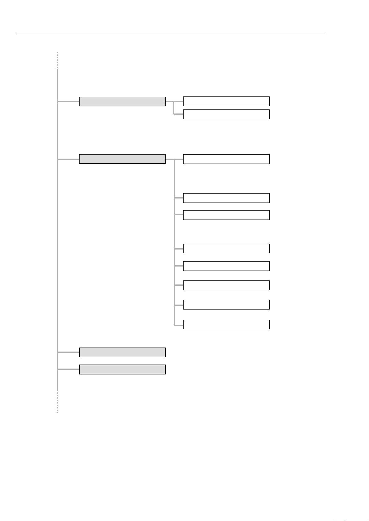
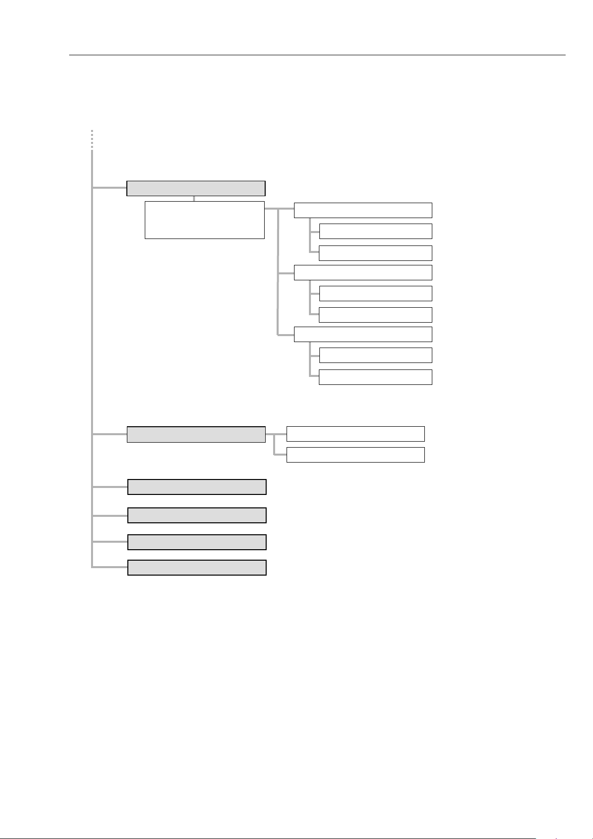
An overview of the menu structure in the programming mode can be found in
section 5.5.
®
F 5673 hum idity measurement s ystem. You can
5.1 General instructions
In the programm ing mode, the humidit y measurement goes on in the background.
After the return to the d isplay mode, the indication is updated in accor dance
with the new programming.
The following sections describe the principles of working with the different
menus and the parameter settings.
The keys can be assigned different functions whose current meaning is
marked by icons.
All keys are touch-sensitive, i.e. you need not press them but only touch
them.
for a marked parameter, an entry dialog or a selection dialog is opened.
dinate menu.
dinate menu.
You quit the menu that is open at present.
All settings/entries (also of the subordinate menus) are taken over and
stored.
All changes will only be stored if you quit the menu by means of this
HYGROPHIL® F 5673 Operating manual, Software version 1.8.x, 387896MDHEN(14.06.2013)
Page 64
Programming
5-2
5.2 Calling up programming mode
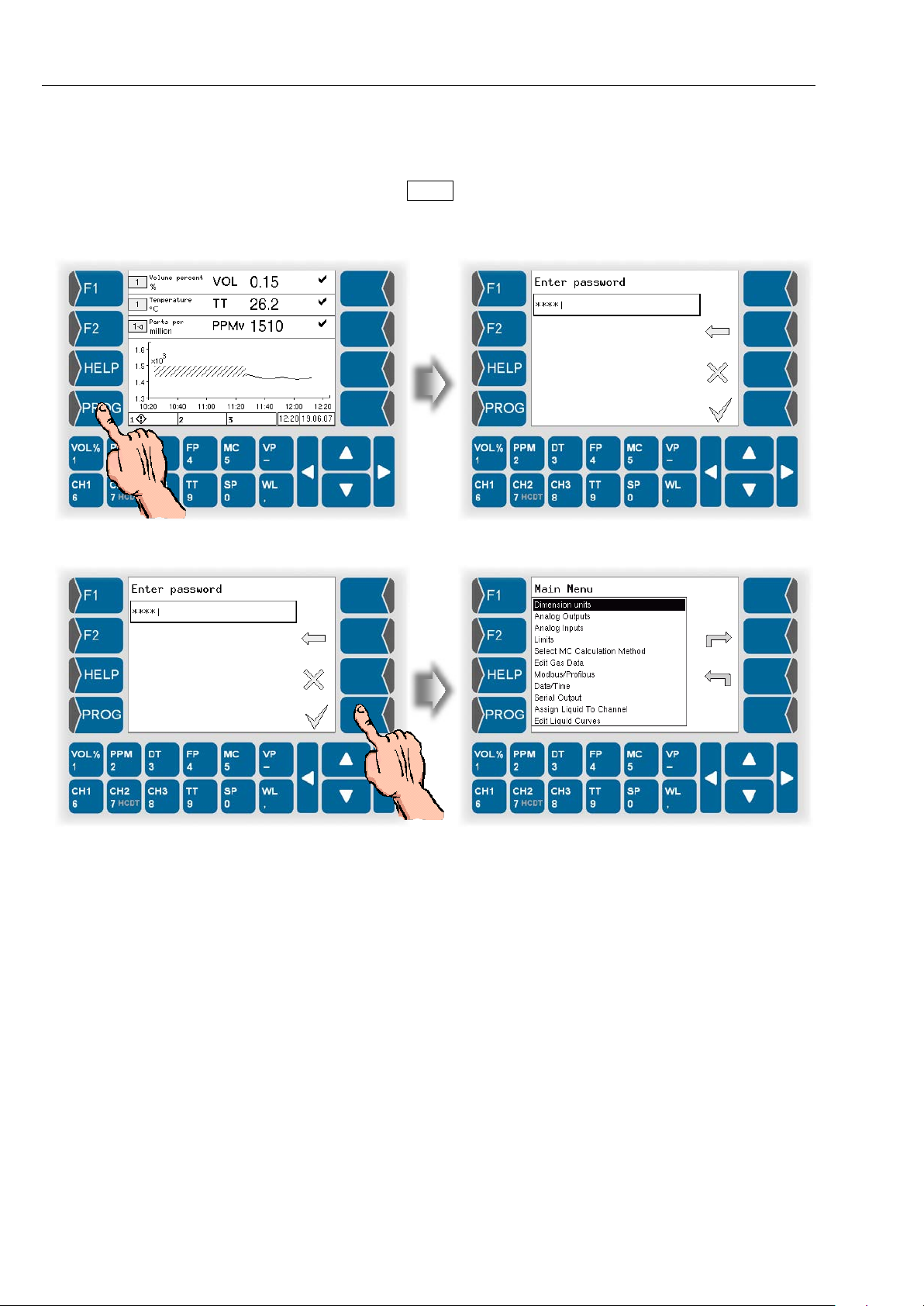
● Touch the PROG key to call up the programming mode.
Then you must enter the password. T he default passwor d is 5673. You can
change the password (see section 5.6.16).
● Enter the valid password and confirm it. The main menu will be opened.
HYGROPHIL® F 5673 Operating manual, Software version 1.8.x, 387896MDHEN(14.06.2013)
Page 65
Programming
5.3 Selecting and opening the menu
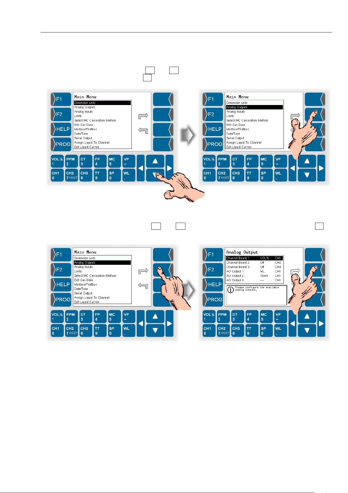
Use and to select the m enu to be opened. Then touch the openkey .
5-3
You can open som e menus onl y after having s elected a s ystem component
(channel board, analogue output ).
Touch and to select a system component and then touch to
open the menu.
HYGROPHIL® F 5673 Operating manual, Software version 1.8.x, 387896MDHEN(14.06.2013)
Page 66
Programming
5-4
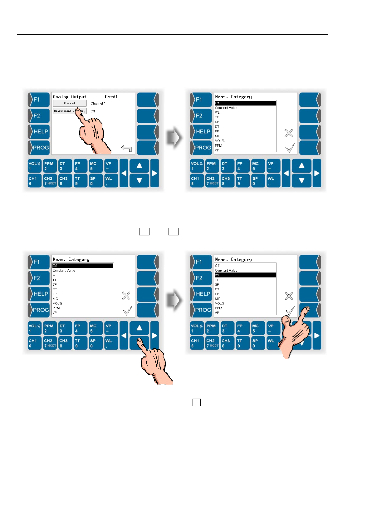
5.4 Editing parameters
● On the display, touch the field whose parameters you want to edit.
5.4.1 Selecting the parameter setting
● Use and to select the required setting, then confirm the
selection.
The change is not saved in the pro gram mem ory unti l you a lso leave th e s uper ordinate menu by using .
HYGROPHIL® F 5673 Operating manual, Software version 1.8.x, 387896MDHEN(14.06.2013)
Page 67
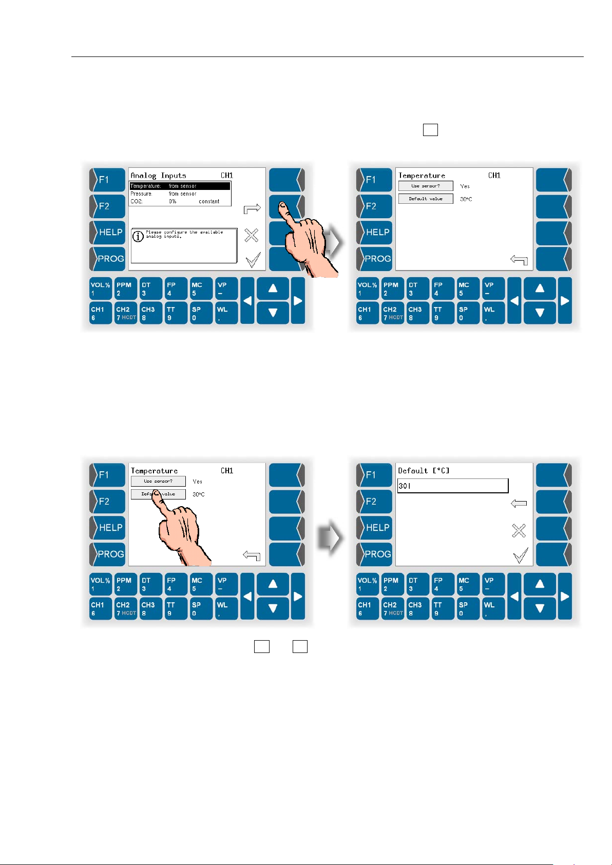
Programming
5.4.2 Selecting the parameters for editing
If the menu contains several parameters which can be edited individually,
first select the param eter and then touc h to open the appropr iate editing
dialog.
5-5
Now you can edit the settings of this parameter.
Either a selection dia lo g (s ee s ect ion 5.4.1) or an entry dialog for the entry of
numerical values (see section 5.4.3) is opened.
5.4.3 Numerical entri es
You can enter numerical values by means of the keys below the display.
The value that was set up to now is displayed after opening the dialog.
Use and to change the position of the cursor.
The delete key (arrow poi nting t o the lef t) is av ailab le for c arr ying out corrections. If you touch this key, the character left to the cursor is deleted.
Touch the OK key to confirm the entry.
HYGROPHIL® F 5673 Operating manual, Software version 1.8.x, 387896MDHEN(14.06.2013)
Page 68
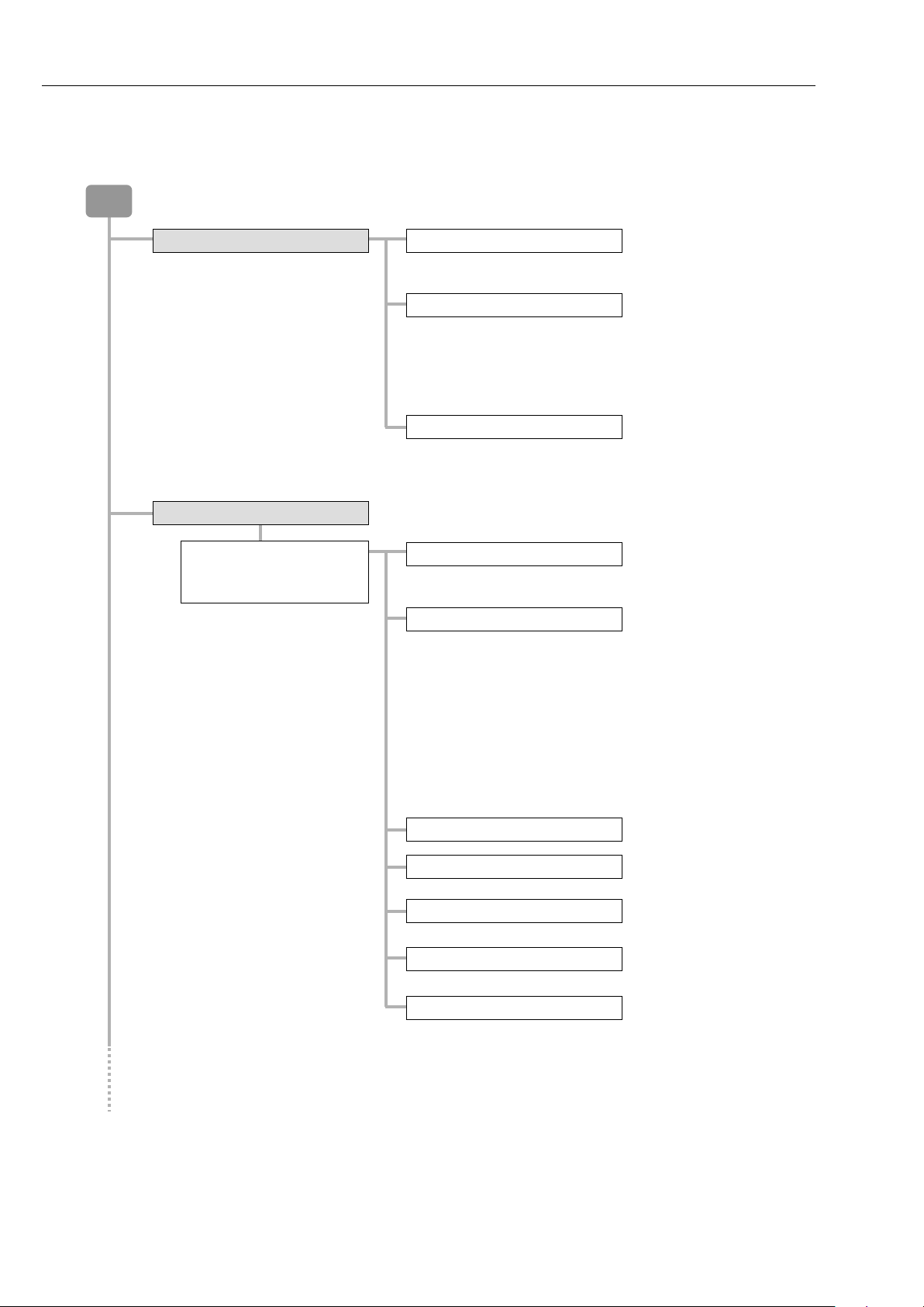
Programming
PROG
Dimension units
Temperature TT / DT / FP
° Celsius
Pressure SP / VP
Pa
psi
Moisture MC
mg/m3
Analog outputs
Channel Board 1
Channel
Channel 1
Off
0...20 mA
4...20 mA
source
sink
Yes
No
Measurement Category
Minimum
Maximum
0/4...20 mA
source/sink
invers
5-6
5.5 Structure of the programming menu
° Fahrenheit
Kelvin
hPa
kPa
bar
mbar
lb/MMscF
Channel Board 2
Channel Board 3
Channel 2
Channel 3
Constant Value
WL
TT
SP
DT
FP
MC
VOL%
PPM
VP
HYGROPHIL® F 5673 Operating manual, Software version 1.8.x, 387896MDHEN(14.06.2013)
Page 69
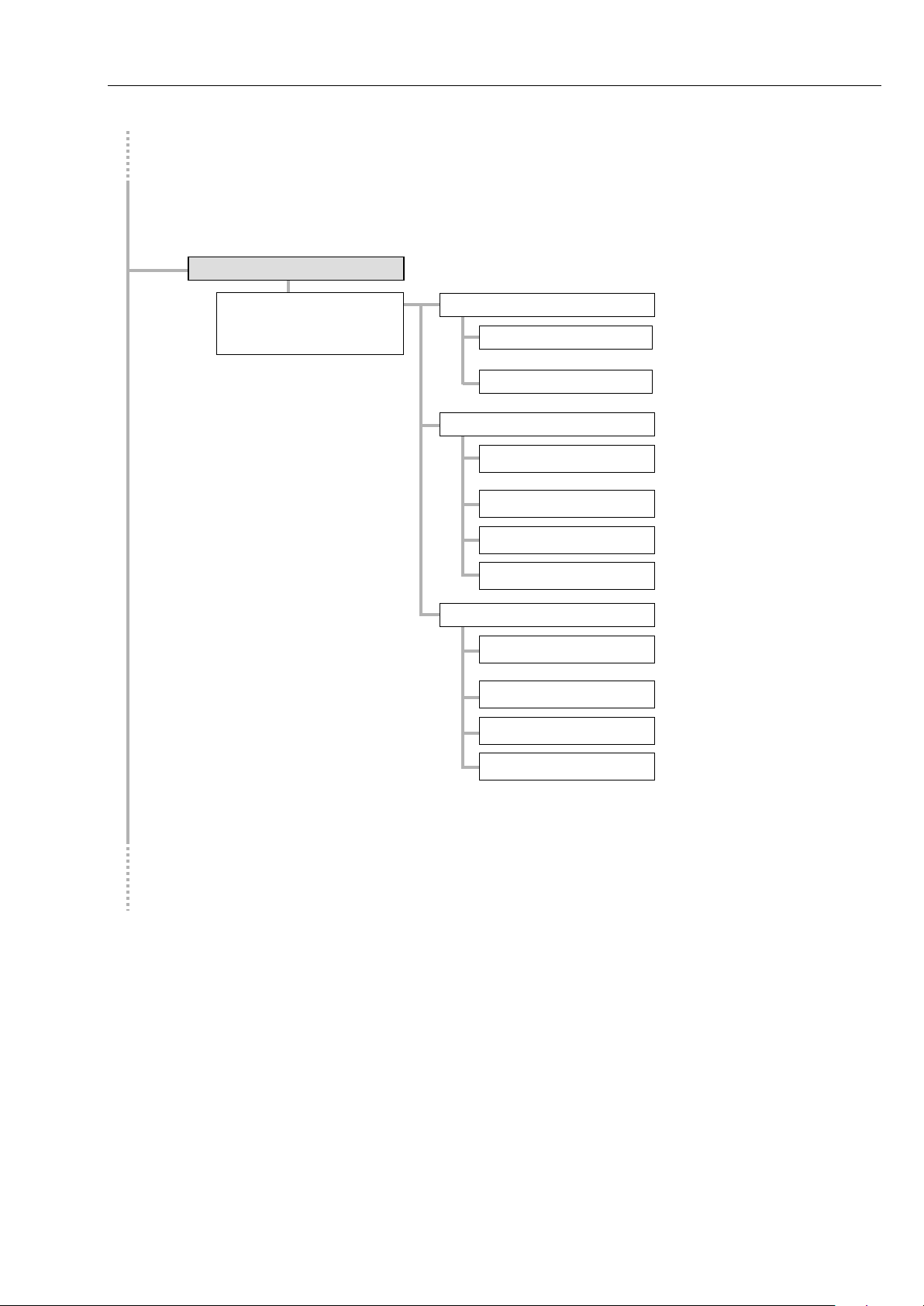
Analog Inputs
Channel 1
Channel 2
Temperature
Use sensor ?
Yes
No
Default value
Pressure
Use sensor ?
Yes
No
Default value
Minimum
Maximum
CO2
Use sensor ?
Yes
No
Default value
Minimum
Maximum
Channel 3
Programming
5-7
HYGROPHIL® F 5673 Operating manual, Software version 1.8.x, 387896MDHEN(14.06.2013)
Page 70
Programming
Limits
Minimum
Maximum
TT
Minimum
Maximum
SP
Minimum
Maximum
DT
Minimum
Maximum
FP
Minimum
Maximum
MC
Minimum
Maximum
VOL%
Minimum
Maximum
PPM
Minimum
Maximum
WL
Channel 1
Minimum
Maximum
VP
5-8
Channel 2
Channel 3
HYGROPHIL® F 5673 Operating manual, Software version 1.8.x, 387896MDHEN(14.06.2013)
Page 71
1200 19200
9600 115200
Modbus/Profibus
Busaddress
Baudrate
Parity
Interface
RS232
RS485
No Parity
Even Parity
Busaddress
Status
Modbus
Profibus
Edit Gas Data
Create gas
Edit gas
User specific gases
Delete gas
View gas
Predefined gases
Select MC Calculation Method
Channel 1
Channel 2
Channel 3
MC calc. method
DIN 1343
ISO 2533
DIN EN ISO 18453
Choose gas
Bukacek
Bartec 2006
Custom User Factor
Choose User MC Factor
Programming
5-9
2400 38400
4800 57600
Odd Parity
HYGROPHIL® F 5673 Operating manual, Software version 1.8.x, 387896MDHEN(14.06.2013)
Page 72
Programming
Date/Time
Date
Time
Assign Liquid To Channel
Edit Liquid Curves
Minimum
Maximum
Off
1 day
1200
19200
7 Databits
8 Databits
1 Stopbit
No Parity
Even Parity
Serial Output
Cycle Time
Package
Baudrate
Number of databits
Number of stopbits
Parity
Yes
No
Send error codes?
LF
CRLF
End of line
5-10
10 seconds
1 minute
10 minutes
1 hour
2400
4800
9600
Odd Parity
HYGROPHIL® F 5673 Operating manual, Software version 1.8.x, 387896MDHEN(14.06.2013)
Page 73
Change Password
Language
English
Russian
System Information
Manufacturer inform ation
Copy service information
! Maintenance Menu !
OK
Cancel
System configuration
Database
OK
Cancel
Reset Configuration to Default
Offset
DT Offset
New Setpo int
Set ΔWL to zero
Channel 1
Channel 2
Channel 3
PPM Offset
New Setpoint
Set ΔWL to zero
ΔWL Offset
New Setpo int
ΔSet ΔWL to zero
Programming
5-11
German
Software version
HYGROPHIL® F 5673 Operating manual, Software version 1.8.x, 387896MDHEN(14.06.2013)
Page 74
Programming
Measurement variable
Dimension
Temperature TT / DT / FP
°Celsius
Kelvin
Pressure SP / VP
Pa
psi
Moisture Content MC
mg/m3
lb/MMscF
5-12
5.6 Program p arameters
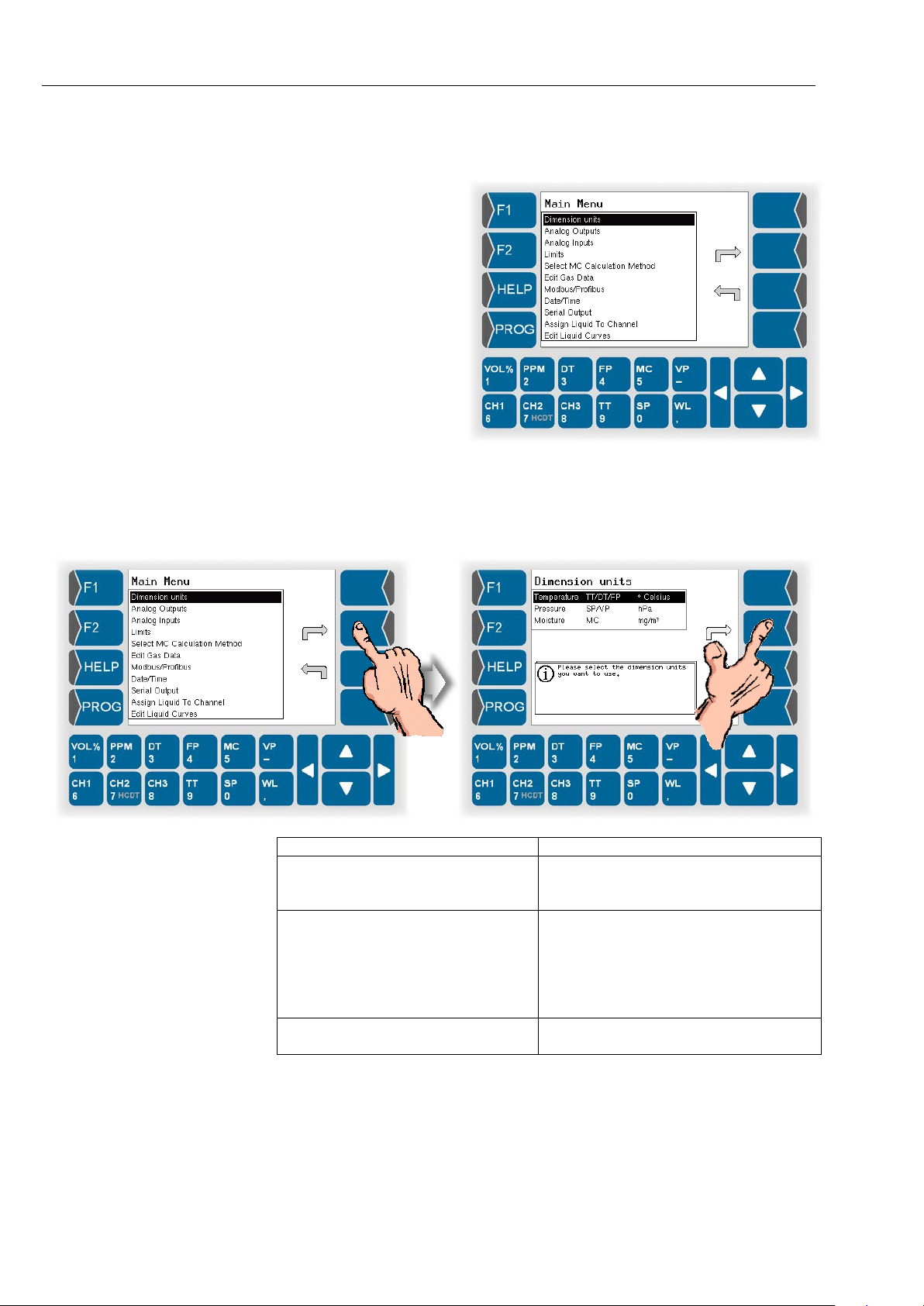
In this section the
meaning of the indiv idual parameters of all
menus is explained.
5.6.1 Dimension units
In this menu you c an define the dim ensions units for temperature, pressure
and moisture content.
°Fahrenheit
hPa
kPa
bar
mbar
HYGROPHIL® F 5673 Operating manual, Software version 1.8.x, 387896MDHEN(14.06.2013)
Page 75
5.6.2 Analog outputs
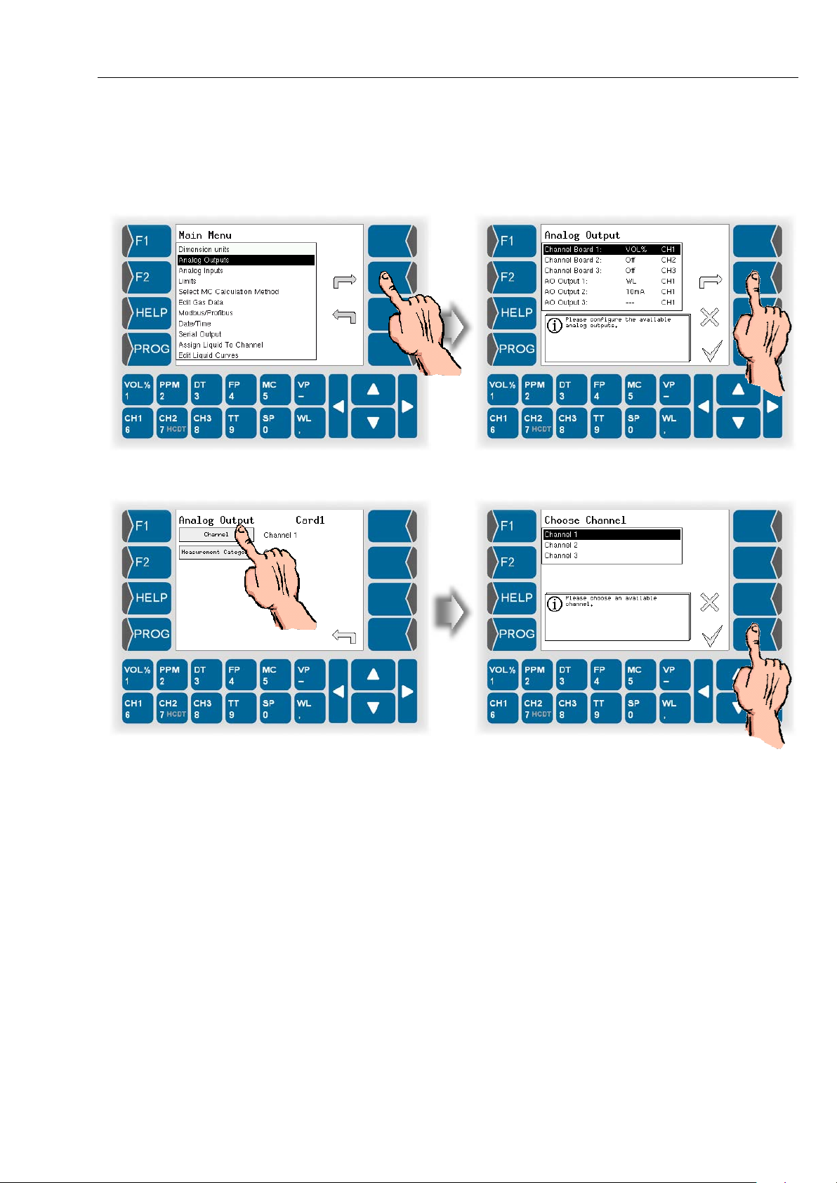
● Open the menu „Analog outputs“.First select an analog output of a
channel board or an analog output of the COM-board to be programmed.
Programming
5-13
Then the programming of the selected analog output takes place.
Channel Select one of the three possible measurement
channels for the analog output.
HYGROPHIL® F 5673 Operating manual, Software version 1.8.x, 387896MDHEN(14.06.2013)
Page 76
Programming
5-14
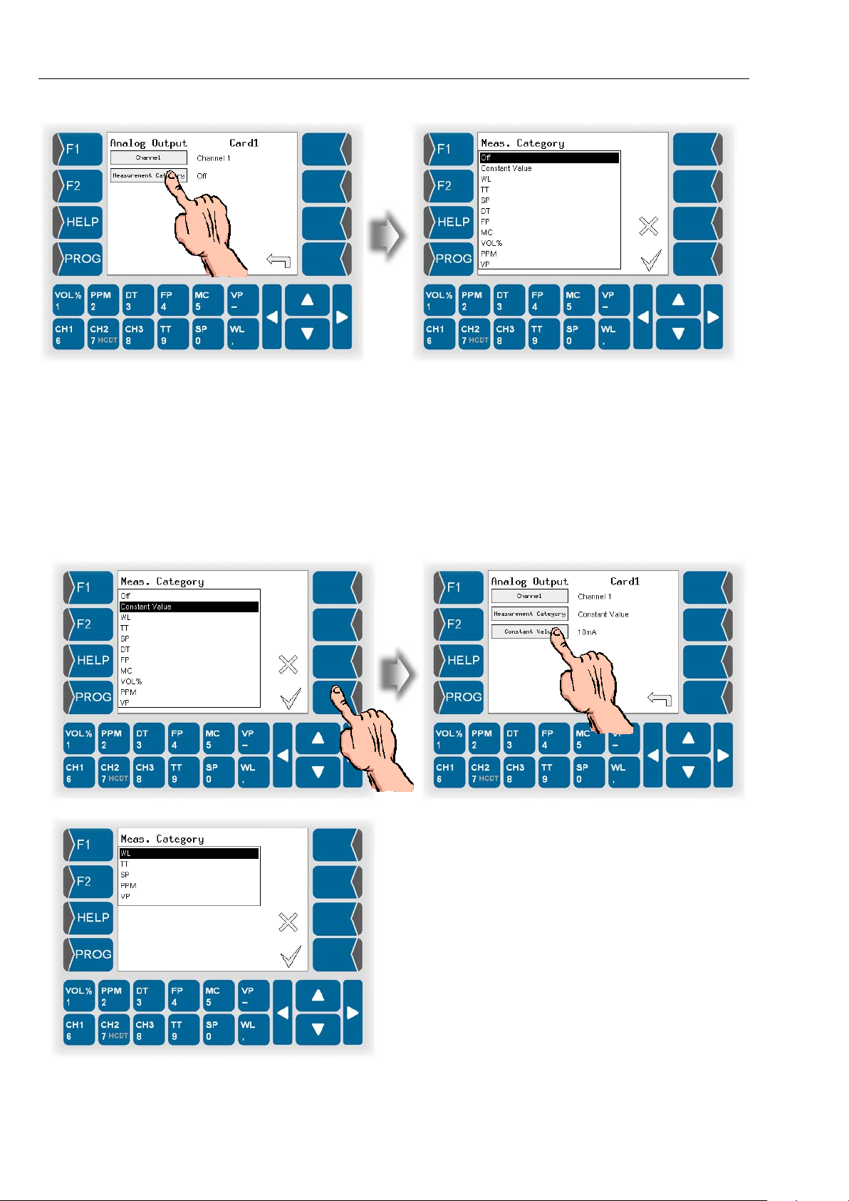
Measurement Category Select the measurement variable to be issued at
the selected analog output.
With the “Off“ setting happ ens no cur rent outp ut at
the selected analog o utput. In this case are no f urther parameter settings available (see fig. above).
You can define a constant value to be output continual instead of a m easuring variabl e. In this case
you must just define the value in the range of
0...20 mA.
When measuring in l iquids are on ly this measur ing
categories available.
HYGROPHIL® F 5673 Operating manual, Software version 1.8.x, 387896MDHEN(14.06.2013)
Page 77
Programming
5-15
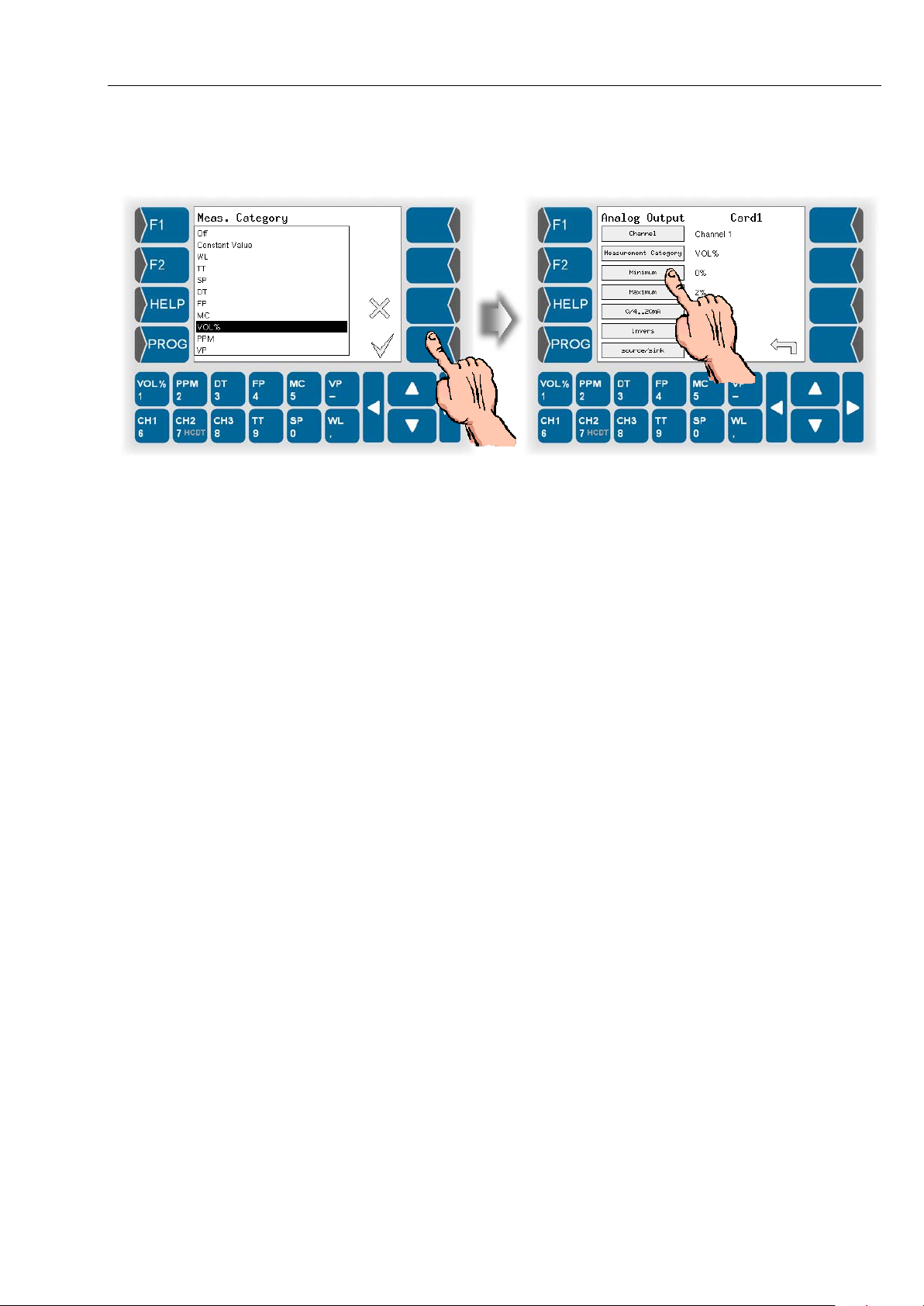
If you have selected a measuring variable to be
output at the selected analog output, you must
configure further parameters.
For each measurem ent variab le you can define a meas urem ent value range
to be evaluated T his range has to be within the possible total measurement
range. You can define the measurement value range with the parameters
„Minimum“ and „Maximum“.
Minimum Setting of the m inimum value for th e meas urement
variable displayed at the analog outp ut. This value
corresponds to 0 and 4 mA respectively.
Maximum Setting of the maximum value for the measure-
ment variable displa yed at the anal og output. This
value corresponds to 20 mA.
0/4...20 Select the output current r ange for the analog out-
put (0...20 mA or 4...20 mA).
invers If you invert the analog output, t he o utp ut c ur rent is
issued inversely proporti onal to the measured value.
source / sink The current signal can function as a source (cur-
rent is issued) or as sink (current is consumed).
This parameter is av ailable for the ana log outputs
of the three channe l boards. With the analog outputs of the COM board („AO output 1...3“) is the
output signal always „source“.
HYGROPHIL® F 5673 Operating manual, Software version 1.8.x, 387896MDHEN(14.06.2013)
Page 78
Programming
5-16
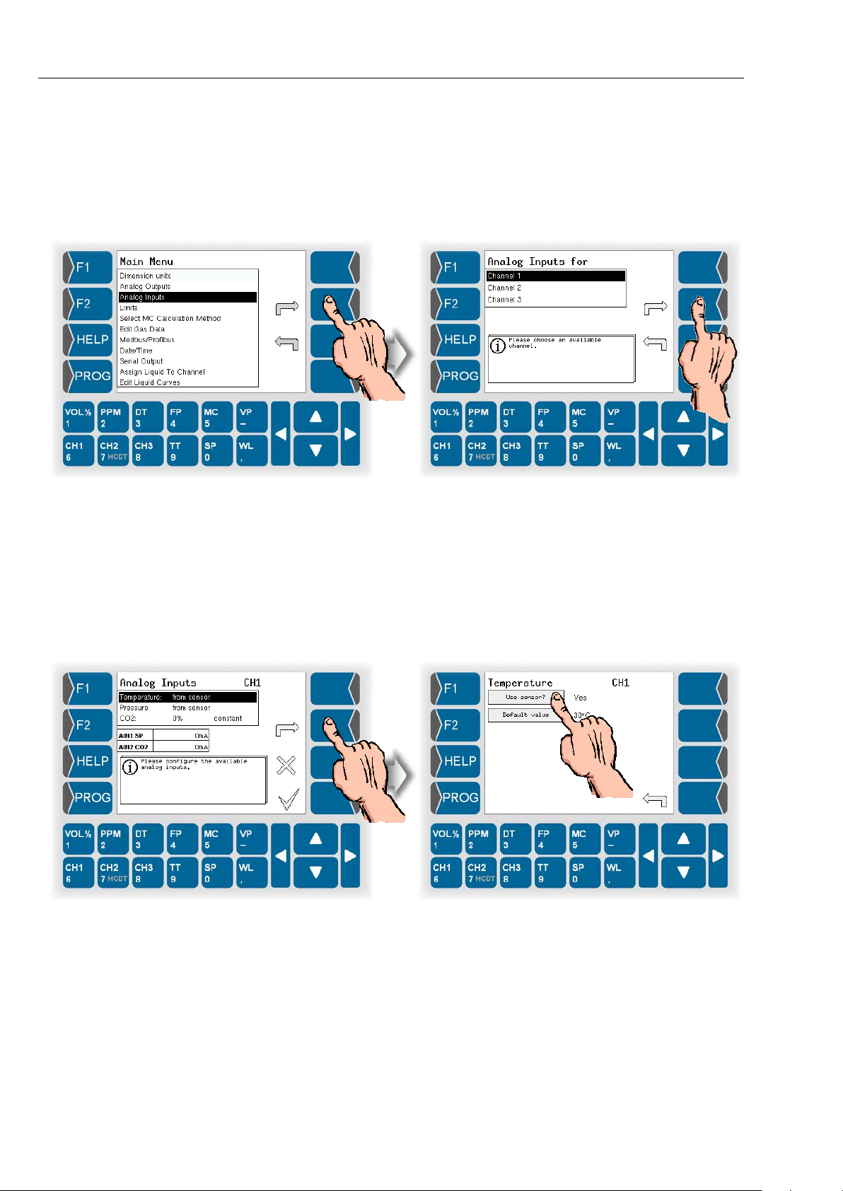
5.6.3 Analog inputs
● Open the menu „Analog Inputs“.
● Choose which one of the three measurement channels you want to
program.
● Then select the m easurement variable to b e measured via the selected
measurement channel.
5.6.3.1 Temperature
● Define whether to use a temperature sensor or not.
● Under Default value, enter a fix ed value. T his fixed val ue will be app lied if
no sensor is used.
HYGROPHIL® F 5673 Operating manual, Software version 1.8.x, 387896MDHEN(14.06.2013)
Page 79
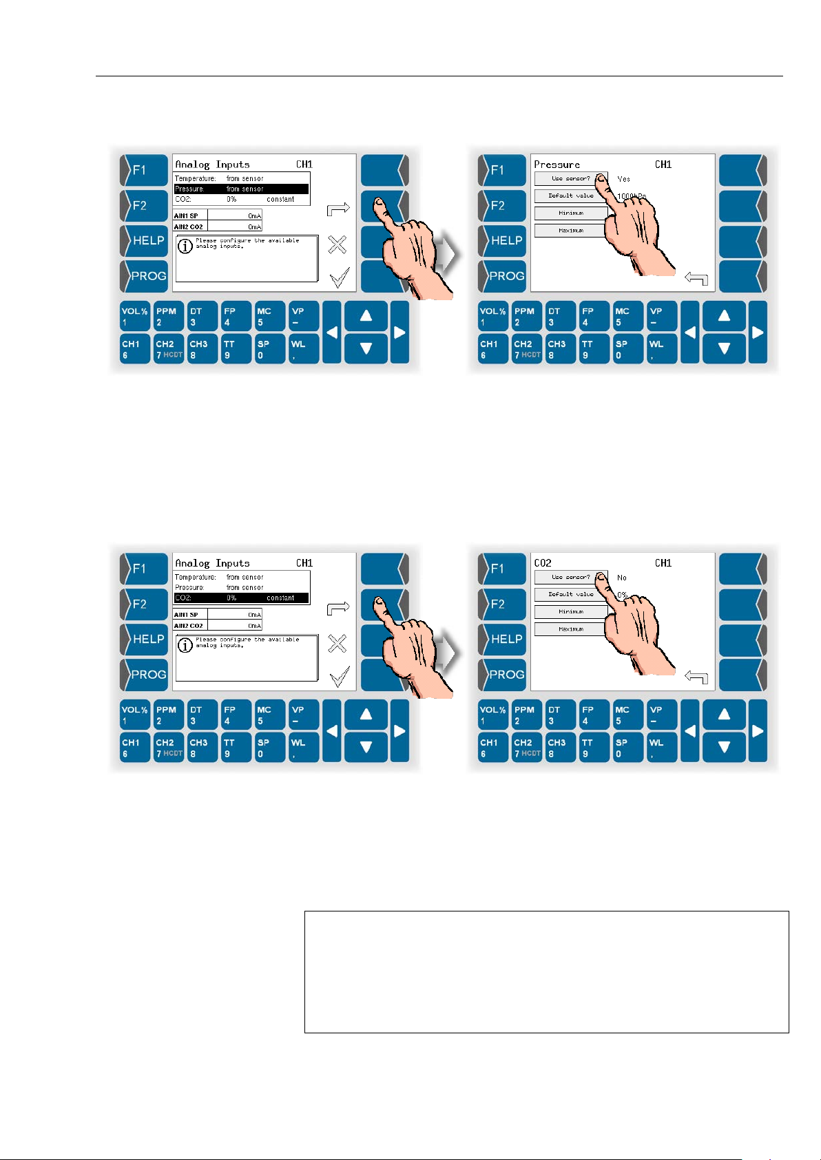
5.6.3.2 Pressure
● Define whether to use a pressure sensor or not.
● Under Default value, enter a fix ed value. T his fixed val ue will be app lied if
no sensor is used.
● Define the measurement range for the current input of pressure.
The minimum value corresponds to an input current of 0 and 4 mA
respectively, the maximum value corresponds to 20 mA.
Programming
5-17
5.6.3.3 CO2 content
● Define whether to use a CO
● Under Default value, enter a fix ed value. T his fixed val ue will be app lied if
no sensor is used.
● Define the measurement range for the current input of CO
The minimum value corresponds to an input current of 0 and 4 mA
respectively, the maximum value corresponds to 20 mA.
Default values
The fixed value that is entered for a measuring var iable will be a pplied if no
sensor is used.
If a sensor should be used but is not con nected or if a conn ected sensor is
defective, the fixed value wil l automatical ly be used. If a fixed va lue is used,
an asterisk appears behind the measured value in the display
(see section 4.3.1.4).
sensor or not.
2
content.
2
HYGROPHIL® F 5673 Operating manual, Software version 1.8.x, 387896MDHEN(14.06.2013)
Page 80
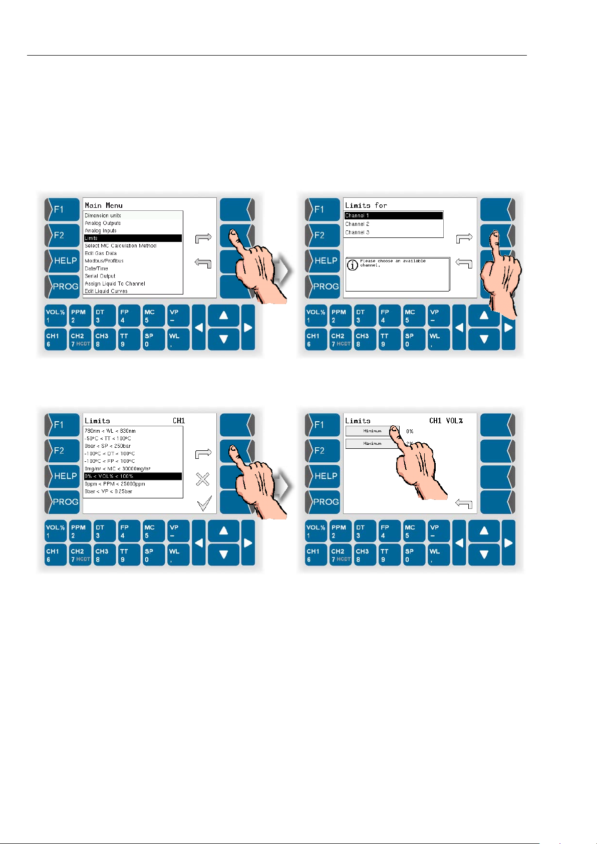
Programming
5-18
5.6.4 Limits
It can be checked whet her the values th at have been m easured or calculated do not infringe the limit values.
● Open the menu „Limits“.
● Choose which one of the three measurement channels you want to
program.
● Select the measurement variable. The currently valid limits are displayed.
● Enter the required minimum and maximum values.
If a value either exc eeds or falls below any lim its, a signal is issued via an
optocoupler.
Icons in the displa y show that a limit has been exceede d or f allen bel o w (s ee
section 4.3.1.5 and 4.3.1.7).
HYGROPHIL® F 5673 Operating manual, Software version 1.8.x, 387896MDHEN(14.06.2013)
Page 81
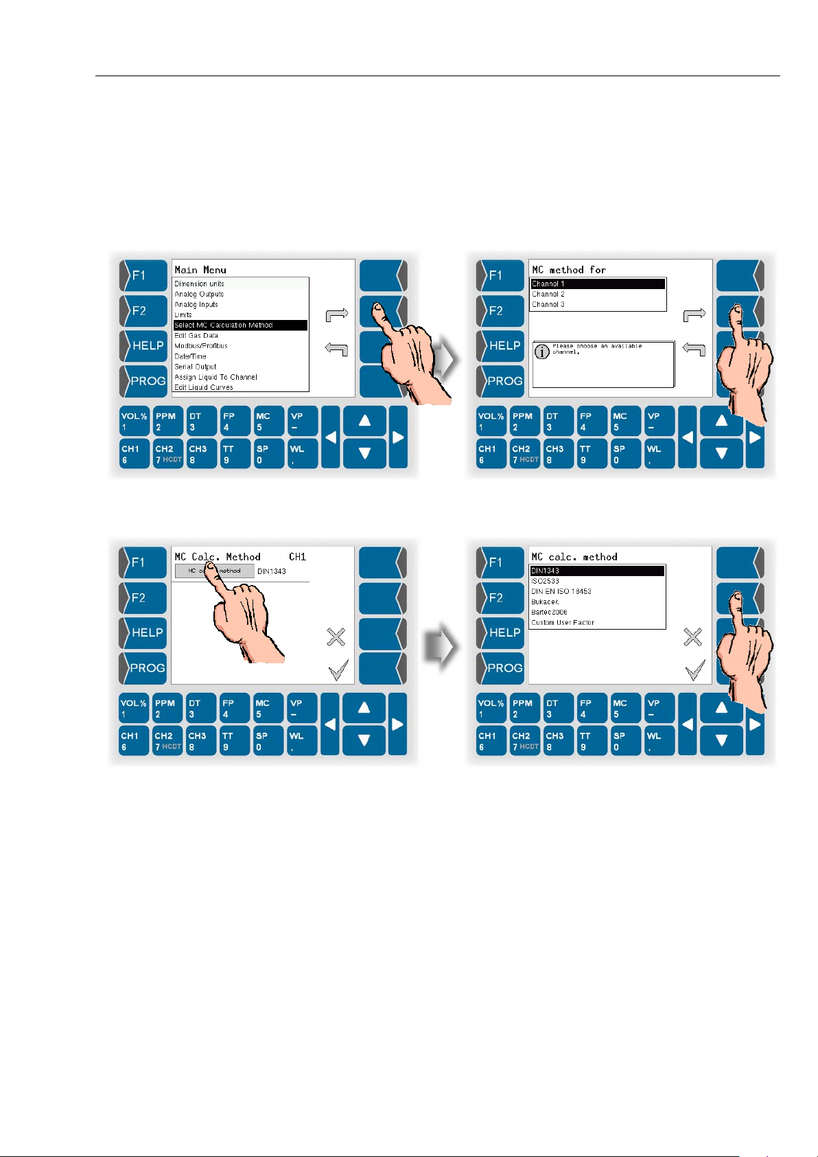
Programming
5.6.5 Selecting the MC Calculation Method
When using HYGRO PHIL® F 56 73 you can sel ect different m ethods for calculating the moisture content MC [mg/m³, lb/MMscf].
● Open the menu „Select MC Calculation Method“.
● Choose one of the available channels for the MC-calculation.
5-19
● Select the method for calculation MC.
DIN 1343
ISO 2533
DIN EN ISO 18453
Bukacek
Bartec 2006
Custom User Factor
You must do further settings when using the calculation method DIN ISO
18453 or Custom User Factor (see below).
HYGROPHIL® F 5673 Operating manual, Software version 1.8.x, 387896MDHEN(14.06.2013)
Page 82
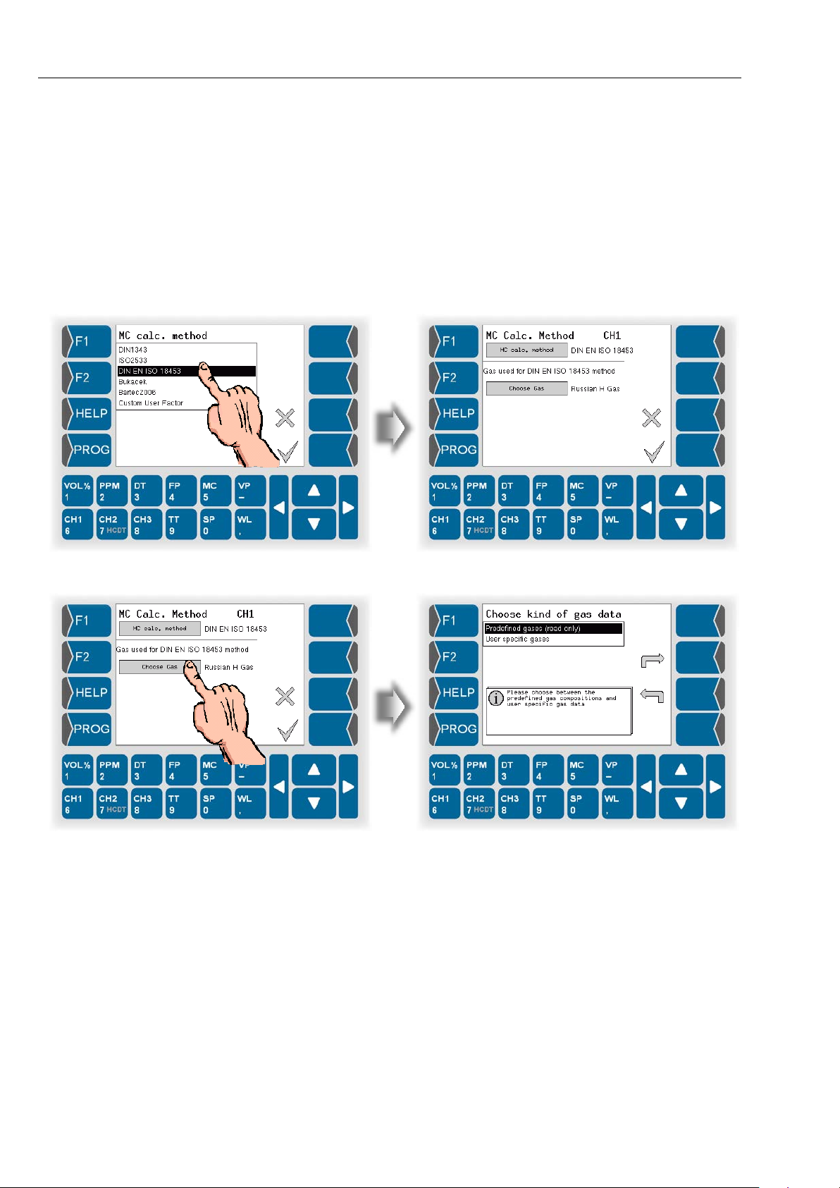
Programming
5-20
DIN EN ISO 18453
DIN EN ISO 18453 „Erdgas – Bezi ehung zwischen W assergehalt und Taupunkt“ defines a m ethod for calculation of water content from the dewpoint
under conditions which are typical for natural gas.
The calculating tolerances defined in this standard apply for the pressure
range from 0.5 MPa to 1 0 MPa and a w ater dewpoint in t he range of -15 °C
to +5 °C. The exp anded working range inclu des pressure from 0.1 MPa t o
30 MPa.
● Select the calculation method DIN EN ISO 18453.
● Select the gas for which the calculation is to apply.
HYGROPHIL® F 5673 Operating manual, Software version 1.8.x, 387896MDHEN(14.06.2013)
Page 83
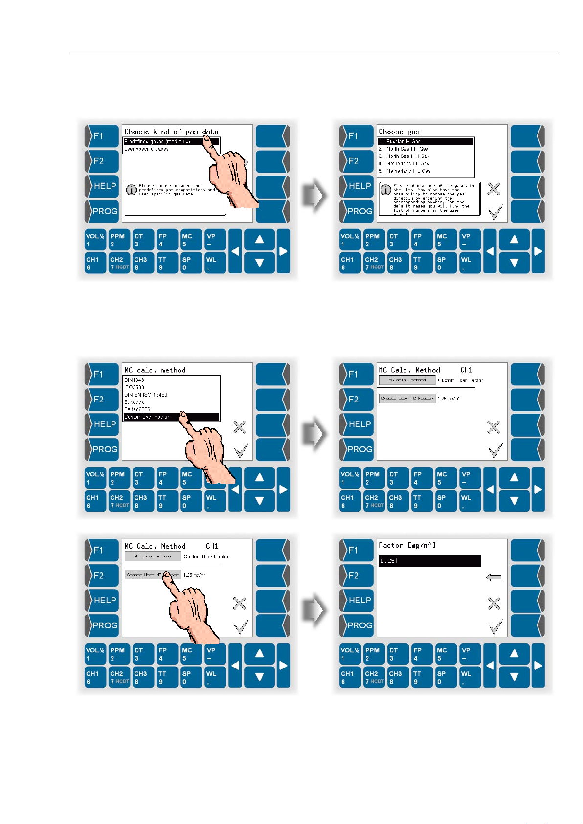
Programming
5-21
You can choose the gas f rom a list of predef ined gas es (see s ection 5.6.6.1)
or from a list of user specific gases (see section 5.6.6.2).
Custom User Factor
For special needs you c a n def ine a f ac tor f or t he con v er sion r at io of ppmV to
MC.
HYGROPHIL® F 5673 Operating manual, Software version 1.8.x, 387896MDHEN(14.06.2013)
Page 84
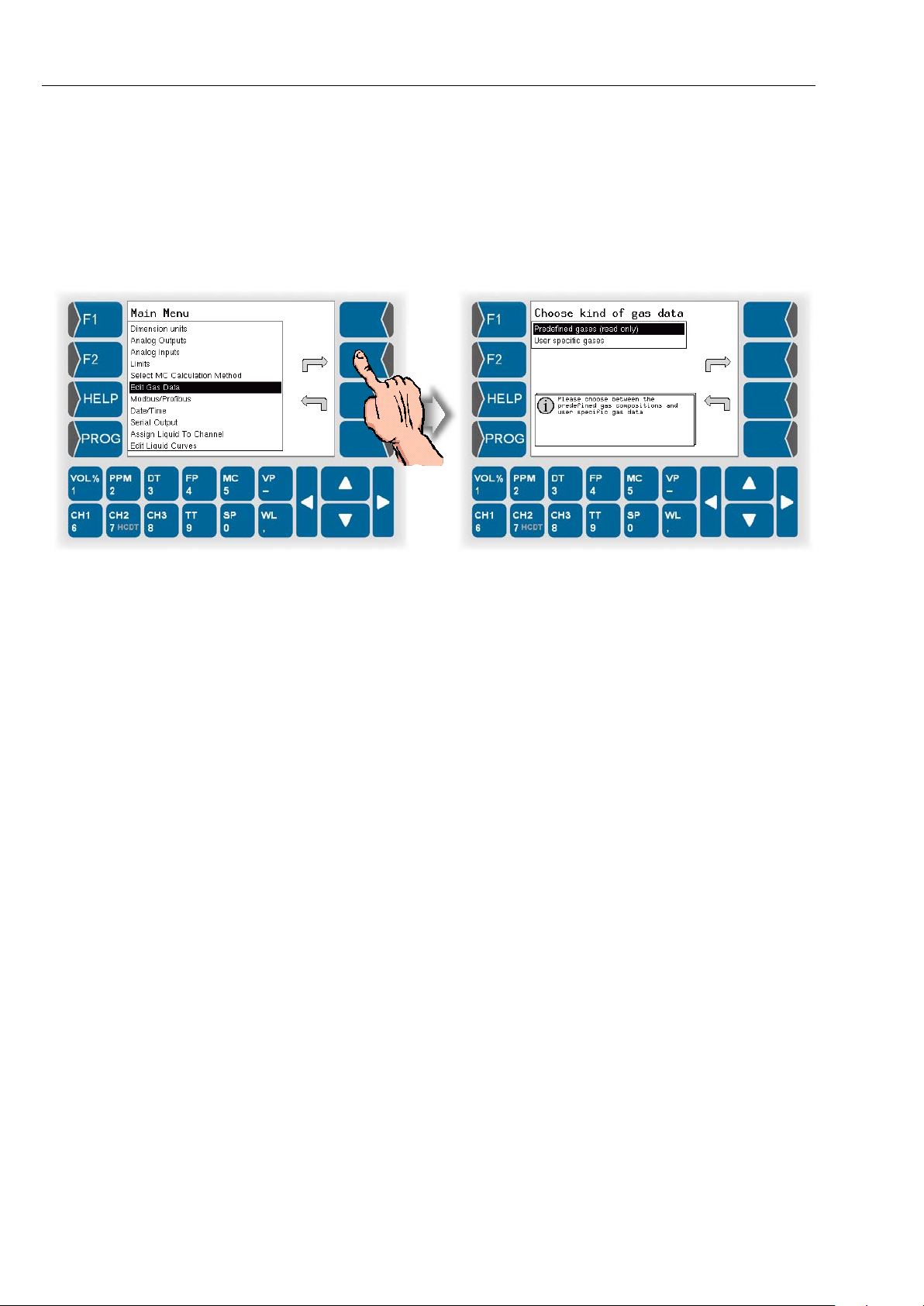
Programming
5-22
5.6.6 Edit Gas Data
The menu is used to view and e dit the com pos ition of user s pecific gases as
well as to view the composition of predefined gases.
● Open the „Edit Gas Data“ Menu. Then choose, if you want to view the
predefined gases or the user specific gases which can also be edited.
HYGROPHIL® F 5673 Operating manual, Software version 1.8.x, 387896MDHEN(14.06.2013)
Page 85
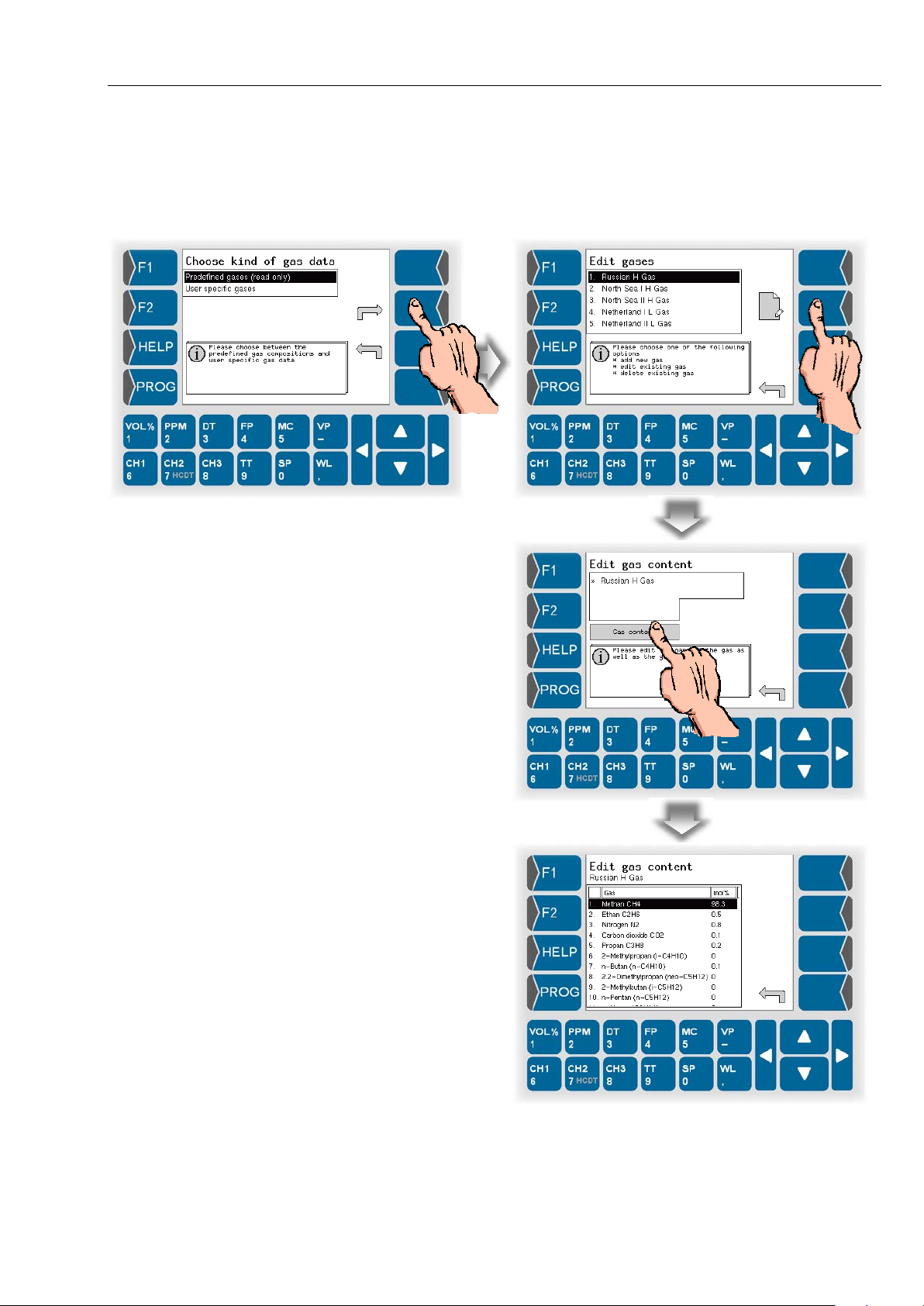
5.6.6.1 Predefined gases
A list of predefined gases exists already when the measur ing system is delivered. You cannot m odify the content of this lis t b ut you c an vie w t he d ef inition of the composition of all gases.
Programming
5-23
There is a table showing the compos ition of the predefined gases at page
9-5.
Source for the list of predefined gases is the worksheet G 260 of DVGW
(Deutsche Vereinigung des Gas- und Wasserfaches e.V.).
HYGROPHIL® F 5673 Operating manual, Software version 1.8.x, 387896MDHEN(14.06.2013)
Page 86
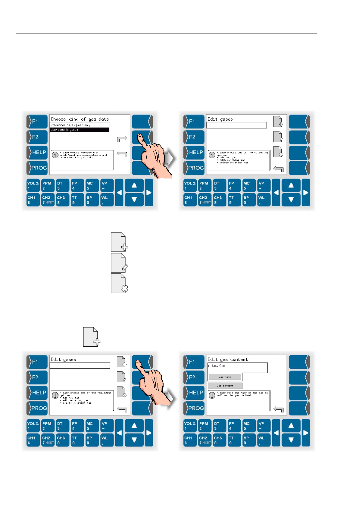
Programming
5-24
5.6.6.2 User specific gases
There are no user specif ic gases entere d when th e measurin g s ystem is delivered. You can def ine gases of any composition ac cording to the special
requirements of the measuring task.
● Open the „User specific gases“ menu.
Then the following options are available:
create a user specific gas
edit a user specific gas
delete a user specific gas
Create a user specific gas
● Touch the „create a user specific gas“ softkey.
A gas named „New Gas“ is created.
HYGROPHIL® F 5673 Operating manual, Software version 1.8.x, 387896MDHEN(14.06.2013)
Page 87
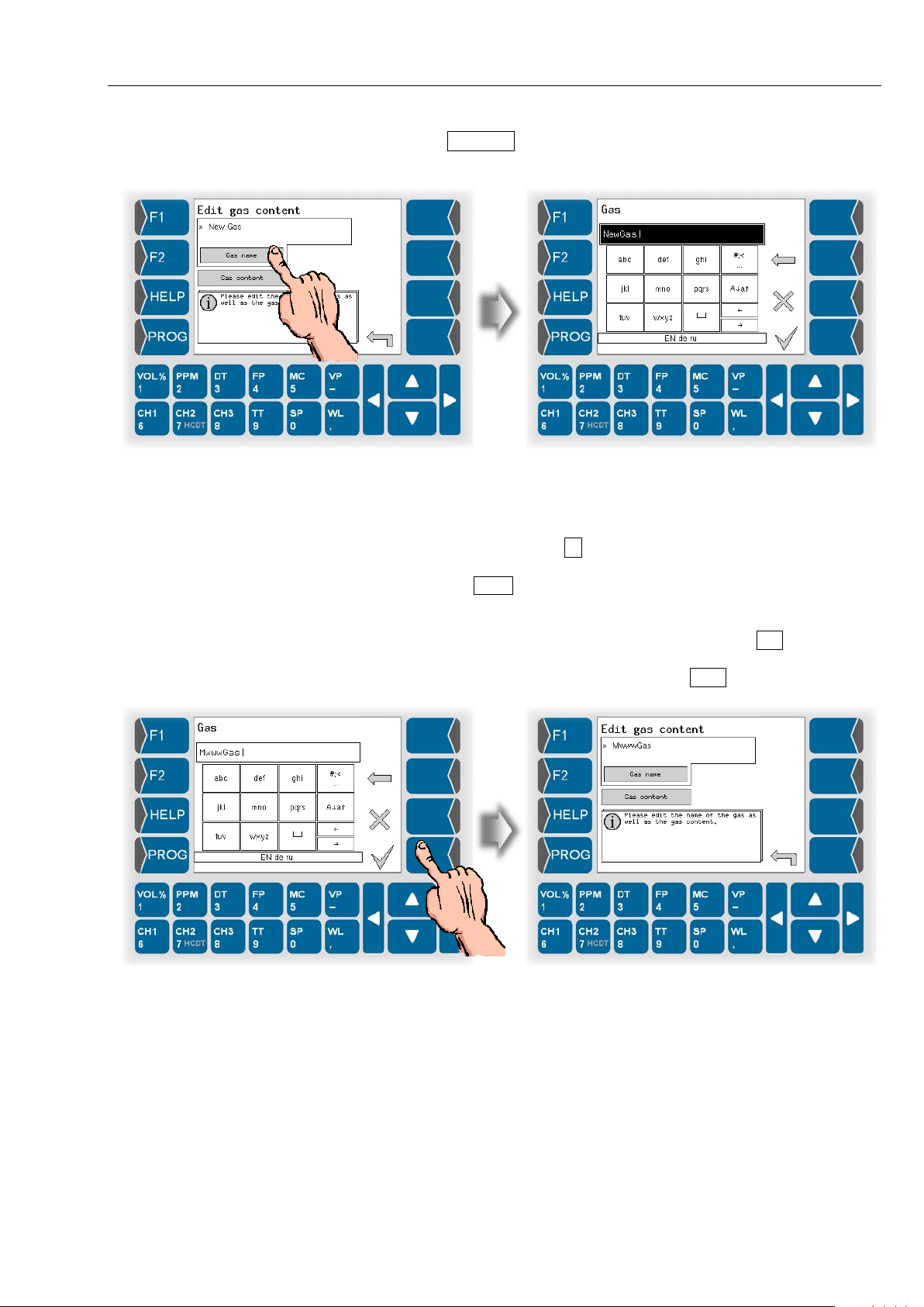
Programming
5-25
● Touch the Gas name bu tton. Us e the fol lowing dial og to c hange th e nam e
of the gas.
Letters are entered us ing the k eys that ar e shown on the dis play. T o enter a
letter, simply touch t he corr espondin g key. T he keys a re assigned u p to f our
characters. You determine which character appears in the input line by
pressing the key the appropriate number of times in quick succession.
You can enter a blank with the ⊔ key.
You can use the A↓a↑ key to switch fr om upper case to lower case letters
and vice versa.
If special characters need to be entered, you can use the #;< key to switch
the key assignment to the special character level. You can switch back to
letters using the same key, which is now labelled abcä .
HYGROPHIL® F 5673 Operating manual, Software version 1.8.x, 387896MDHEN(14.06.2013)
Page 88
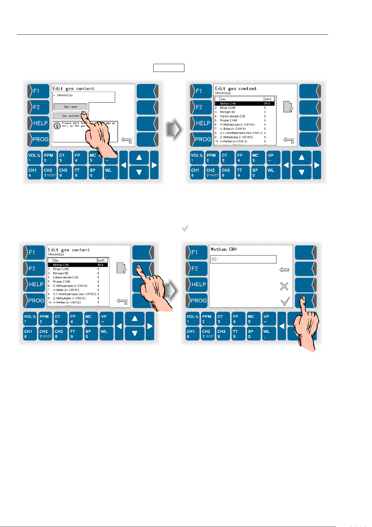
Programming
5-26
With the next step you must enter the composition of the gas.
● Touch the Gas content button.
● Select one of the com ponents of the mixture b y using the arrow keys or
touching the corresponding numeric key.
● In the following dialog enter the percentage of the selected substance.
● Confirm the entry by
.
● Repeat the entry of the p ercentages for all other substanc es in the gas
mixture.
HYGROPHIL® F 5673 Operating manual, Software version 1.8.x, 387896MDHEN(14.06.2013)
Page 89
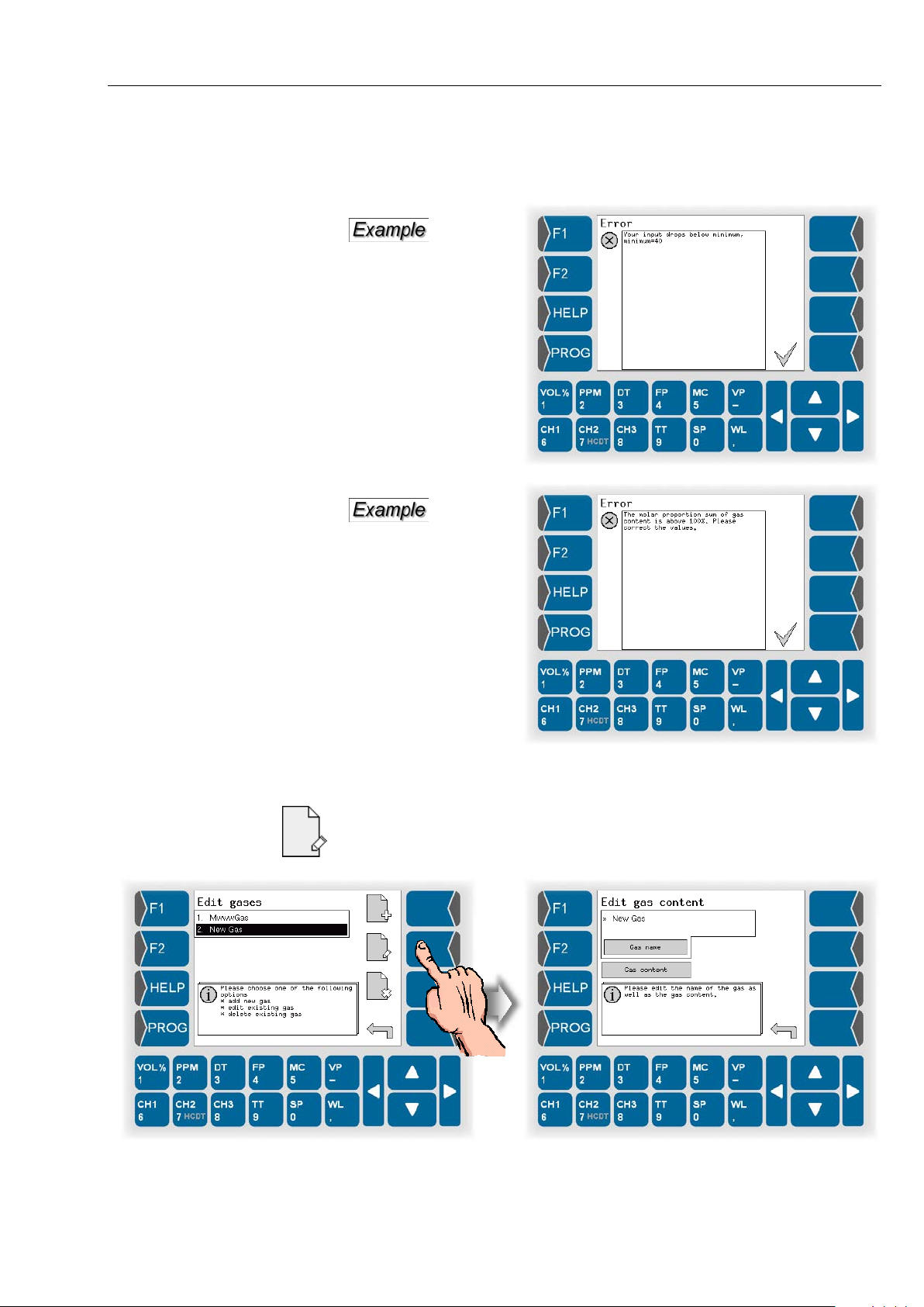
Programming
5-27
When enter ing the gas content, the soft ware checks the validity of the entries. If entries are outside of the measuring range or if the sum would exceed 100% is an accordingly message displayed.
Edit a user specific gas
Select the gas, whose data you want to edit. Touch the „Edit“ softkey.
Then you can edit the name and the composition of the gas as described
above.
HYGROPHIL® F 5673 Operating manual, Software version 1.8.x, 387896MDHEN(14.06.2013)
Page 90
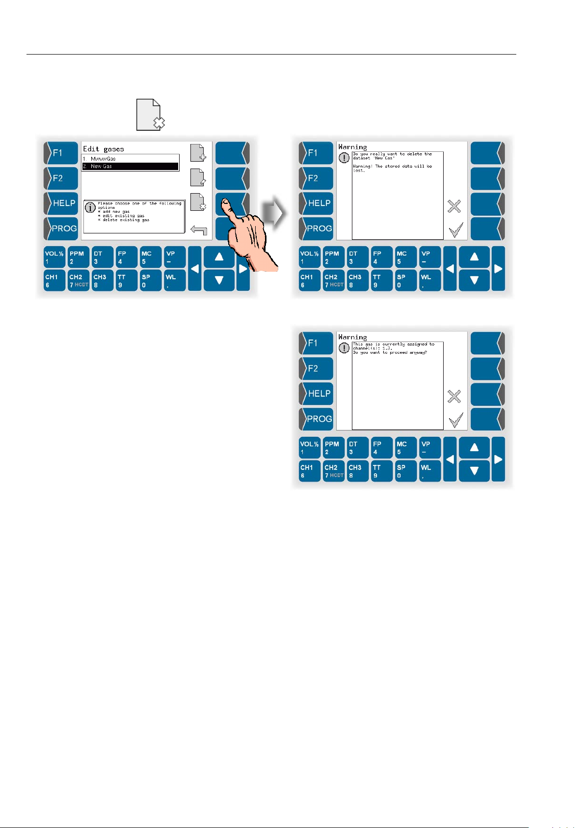
Programming
5-28
Delete a user specific gas
Select the gas that you want to delete from the list. Touch th e „Delete“ softkey.
After confirming the warning is the selected gas deleted from the list.
The gas can also be
deleted if it is already
assigned to the measuring channel.
In this case you must
update the configuration of the MC calculation.
HYGROPHIL® F 5673 Operating manual, Software version 1.8.x, 387896MDHEN(14.06.2013)
Page 91
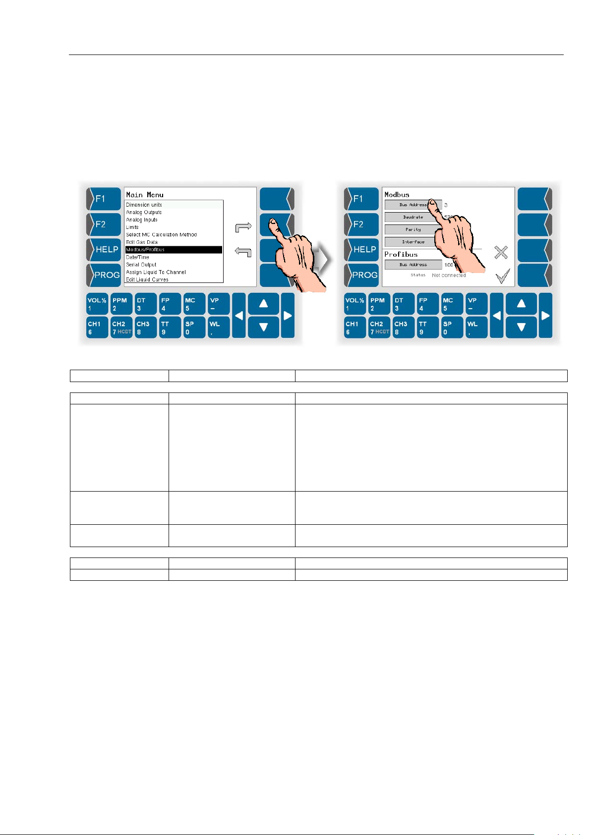
5.6.7 Modbus/Profibus
Parameter
Possible settings
Comments
Modbus
Bus Address
Address of the measuring device
Baudrate
1200
115200
Parity
No Parity
Even Parity
Interface
RS232
RS485
choosing the type of interface to be used
Profibus
Bus Address
Address of the measuring device
Status
Display of status information
Use this menu to configure the m easur ing system f or operating in a bus system (modbus or profibus).
● Open the menu „Modbus/Profibus“.
● Set the parameters according to the applied bus system.
Programming
5-29
2400
4800
9600
19200
38400
57600
Odd Parity
Detailed information to the bus systems see section 8.
HYGROPHIL® F 5673 Operating manual, Software version 1.8.x, 387896MDHEN(14.06.2013)
Page 92
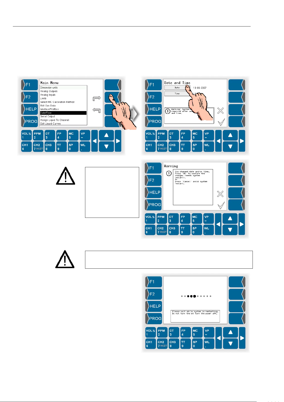
Programming
5-30
5.6.8 Date and time
● Open the menu „Date/Time“.
● Set the current date and time.
Please mind that the
device will be reboot ed
if you save these settings.
Do not implement
these settings if the
ongoing measurement
process must not be
interrupted!
If you change the date or the time, the operating volt age has to be applied
until the device is back in the measuring operation mode. Discon nection of
the voltage will cause a data loss.
This message appears
during the restarting
process:
HYGROPHIL® F 5673 Operating manual, Software version 1.8.x, 387896MDHEN(14.06.2013)
Page 93
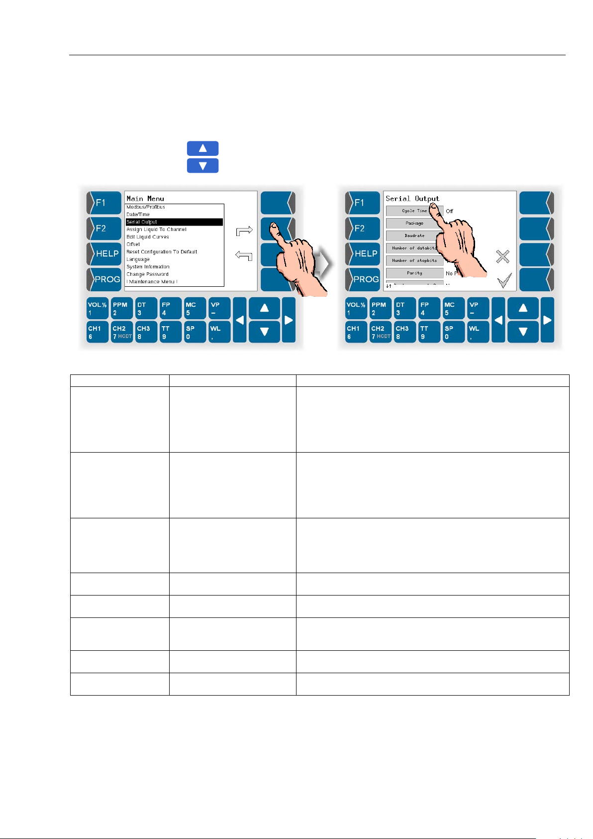
5.6.9 Serial output
Parameter
Possible settings
Comments
Cycle Time
Off
1 day
Time interval after which there is an output to the serial inter-
Package
Minimum
Number of measurement variables issued per record.
relay, state of
Limit-relay)
Baudrate
1200
19200
Number of databits
7 Databits
8 Databits
Number of stopbits
1 Stopbit
2 Stopbits
Parity
No Parity
Even Parity
Send error codes?
Yes
No
You can choose output the error codes or not.
End of line
LF
CRLF
Code to be used for end of line (depending on operating system)
● Open the menu „Serial output“.
● Set the parameters of the serial output as required.
Use the arrow keys to scroll the window.
Programming
5-31
10 seconds
1 minute
10 minutes
1 hour
Maximum
2400
4800
9600
Odd Parity
face.
(Min: Date, Time, Channel, TT, SP, HCDT, DT, state of ER-
ROR-relay, state of Limit-relay)
Max: Date, Time, Channel, TT, SP, WL, VOL%, PPM, DT,
HCDT,FP, MC, VP, state of ERROR-
HYGROPHIL® F 5673 Operating manual, Software version 1.8.x, 387896MDHEN(14.06.2013)
Page 94
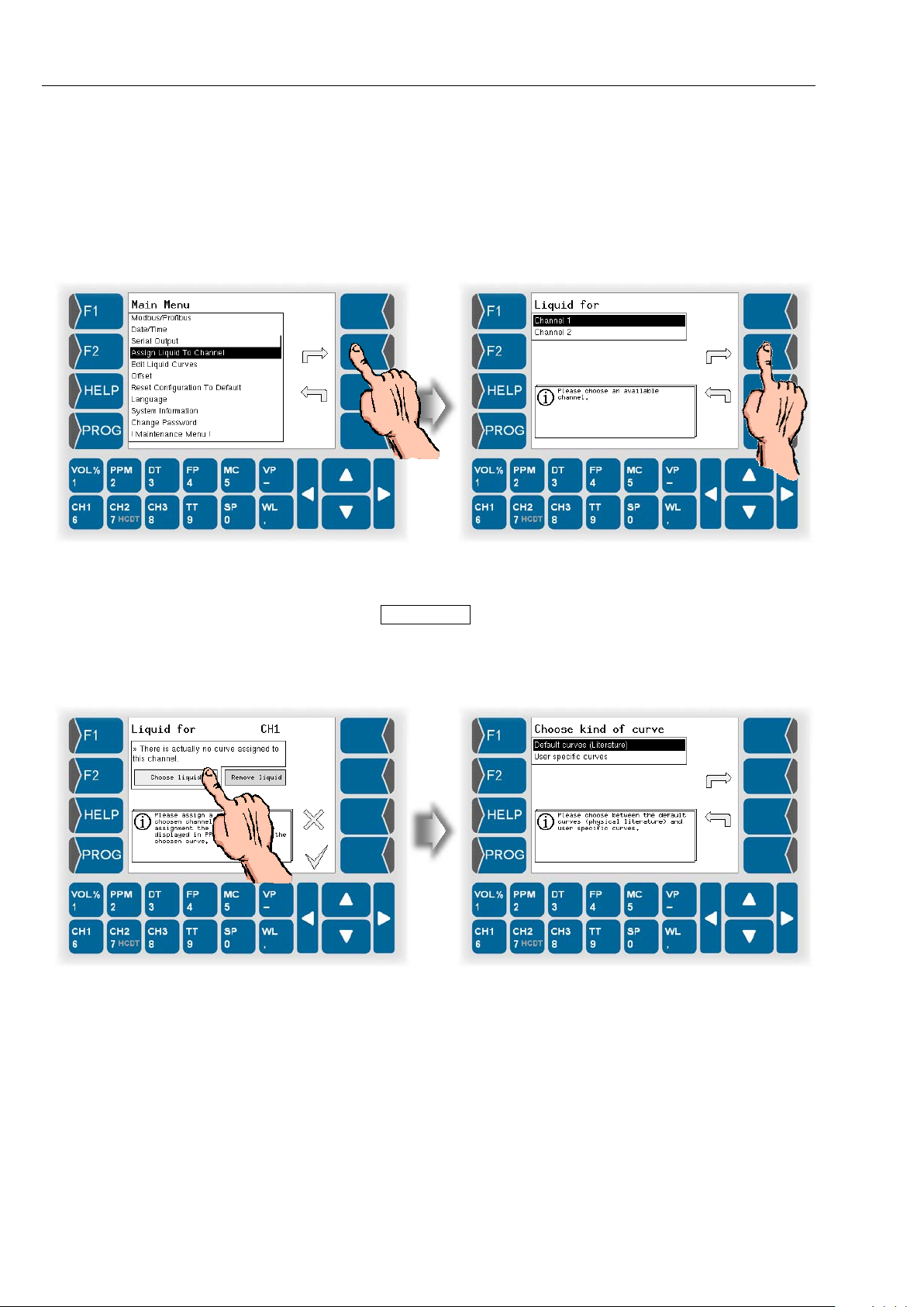
Programming
5-32
5.6.10 Assigning a liquid to a channel
To measure the m oisture i n liquids you must as sign a character istic curve of
a liquid to a channel.
● Open the menu “Assign Liquid To Channel”.
● Then select the channel to be used for measuring in a liquid.
When opening this m enu for the first time there is not yet a curve as signed
to the channel.
● Touch the Choose Liquid button.
● Then you can deci de to use one of the default curves or a user specific
one.
The device is delivered just with default curves.
HYGROPHIL® F 5673 Operating manual, Software version 1.8.x, 387896MDHEN(14.06.2013)
Page 95
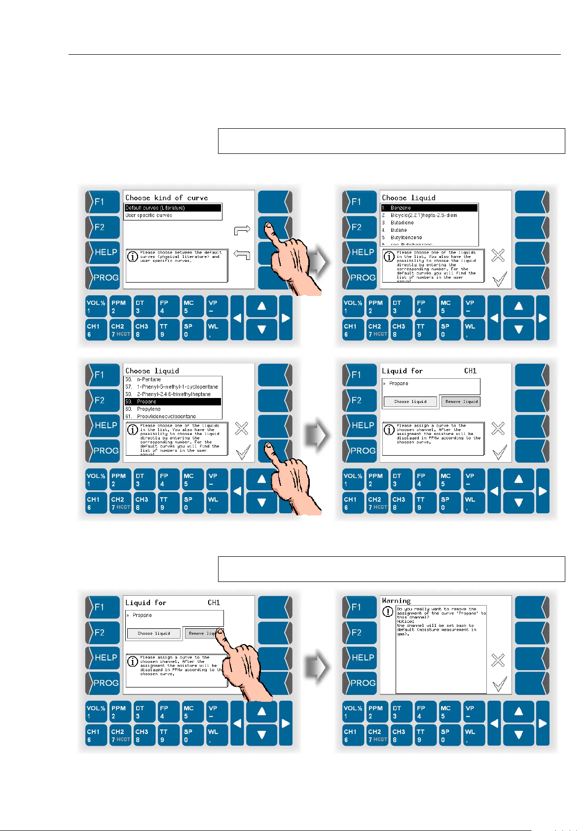
5.6.10.1 Default curves
The default curves („Literature“) which ar e delivered with the device cannot
be edited.
You find an overview of the ava ilable default curv es in the appendix at page
9-3.
● Choose the liquid that is matching to your measuring task. Use the
selection keys or just the corresponding numeric key for choosing.
Programming
5-33
As soon as you confirm the selected liquid curve is HYGROPHIL
®
F in the
selected channel ready for moisture measurement in liquids.
To return to m oistur e measurement in gases, you must rem ove the as s i gne d
curve.
HYGROPHIL® F 5673 Operating manual, Software version 1.8.x, 387896MDHEN(14.06.2013)
Page 96
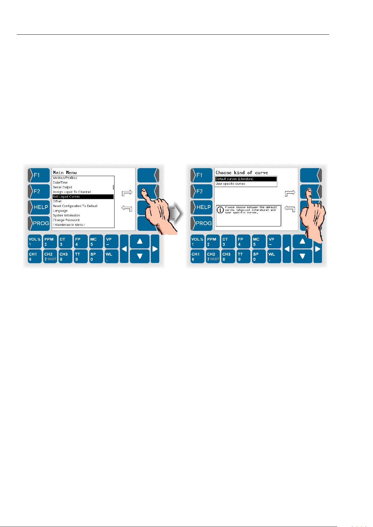
Programming
5-34
5.6.10.2 User specific curves
5.6.11 Edit Liqiuid Curves
User specific curves are not present when delivering the device.
To use such a curve you must create at least one curve (see page 5-35).
Assigning of a user specific curve is to d o in the same way as as signing a
default curve.
This menu is used to edit resp. to view liquid curves.
● Open the menu „Edit Liqiuid Curves“.
● Then choose if you want to view the defaul t curves or edit user s pecific
curves.
5.6.11.1 Default curves
With the menu „Def ault curves“ you can o nl y view data of the def ault curves.
Data of that curves cannot be changed.
HYGROPHIL® F 5673 Operating manual, Software version 1.8.x, 387896MDHEN(14.06.2013)
Page 97
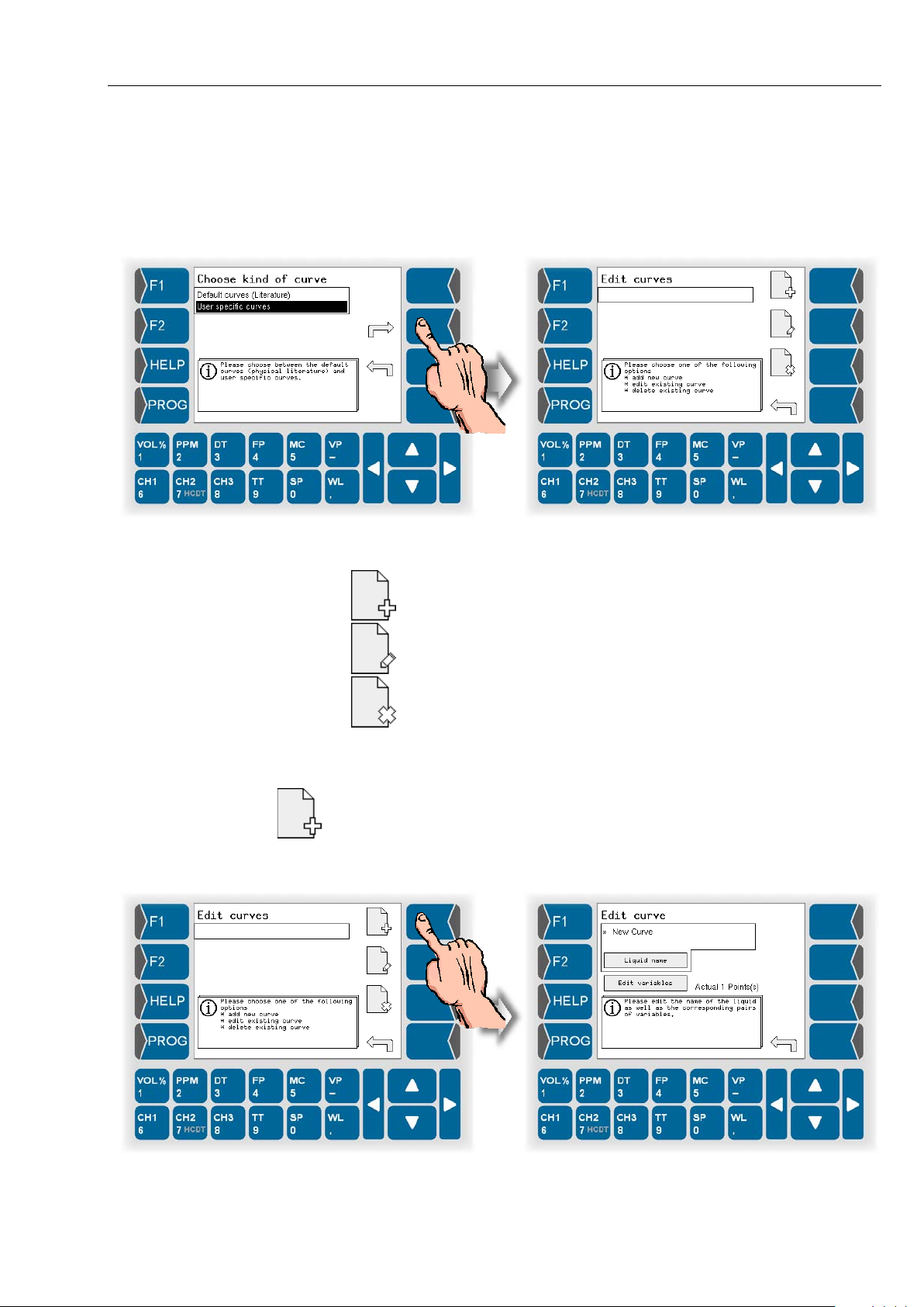
5.6.11.2 User specific curves
You can create curves which are specifically designed for your measuring
task.
Open the menu for editing of user specific curves.
Programming
5-35
Choose from the following options:
Create a new curve
Edit a curve
Delete a curve
Create a new curve
User specific curves are not present when delivering the device.
To use such a curve you must create at least one curve.
● Touch the „Create curve“ key.
A new curve with the name „New Curve“ and the point 0/0 is created.
HYGROPHIL® F 5673 Operating manual, Software version 1.8.x, 387896MDHEN(14.06.2013)
Page 98
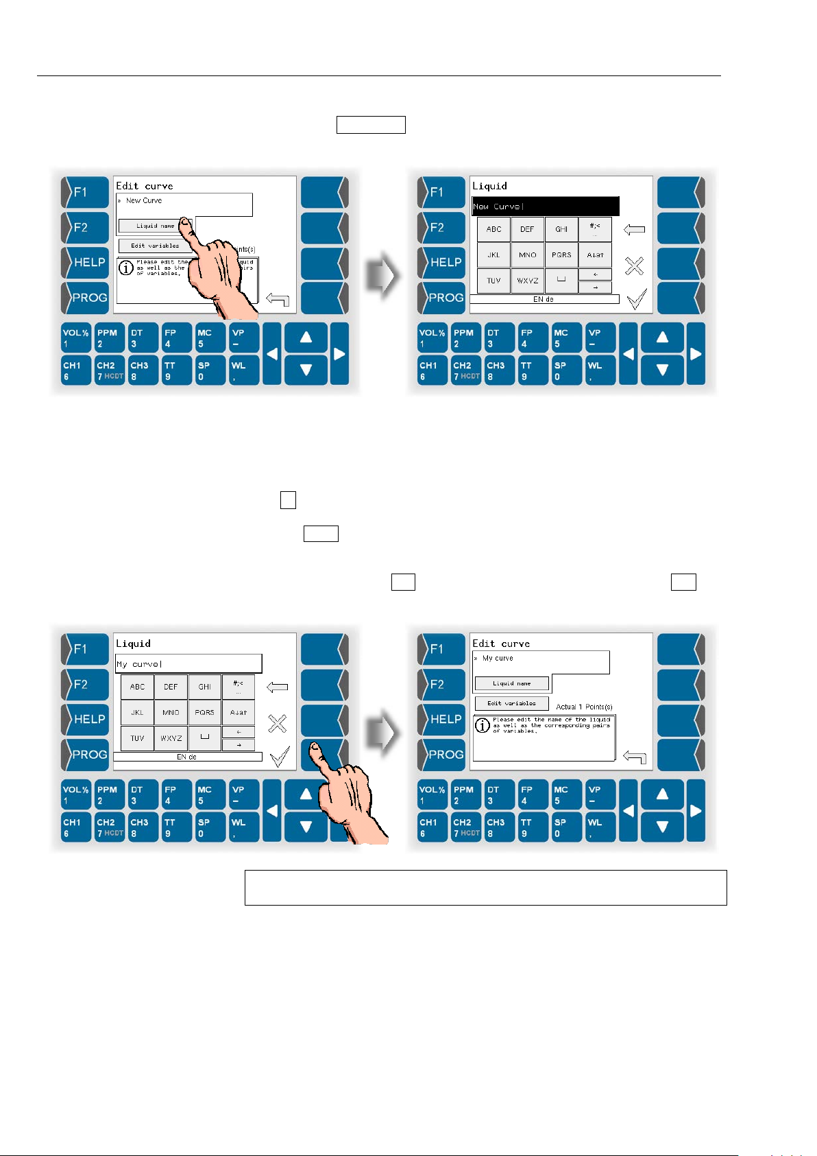
Programming
5-36
● Touch the Liquid name button.
In the following dialog you can create resp. edit the name of that curve.
To enter letters use the k eys displayed on the sc reen. A ke y can be used to
type up to four characters.
The number of k eystrokes specif ies the character that appears in the in put
line.
The ⊔ key generates a space.
Use the A↓a↑ key to switch from capital letters to small letters and back.
To enter special characters, you can switch to the special character key-
board layout with the #;< key. Use the same key (designed with abc ) to
switch back to the standard keyboard layout.
To specify the points of th e curve you must execute a reference m easurement that determines the pairs of variates for T and PPMw.
HYGROPHIL® F 5673 Operating manual, Software version 1.8.x, 387896MDHEN(14.06.2013)
Page 99
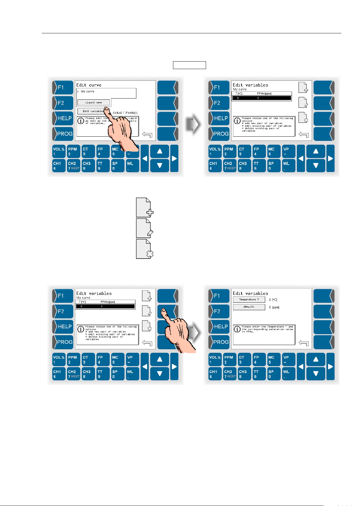
Next step is to transfer the found pairs of variates into the curve.
● Touch the Edit variables button.
Programming
5-37
Then you can choose from the following options:
Add a new point
Edit variates of the point
Delete a point
● Touch the „Edit“ key to enter the pair of variates for the first point.
HYGROPHIL® F 5673 Operating manual, Software version 1.8.x, 387896MDHEN(14.06.2013)
Page 100
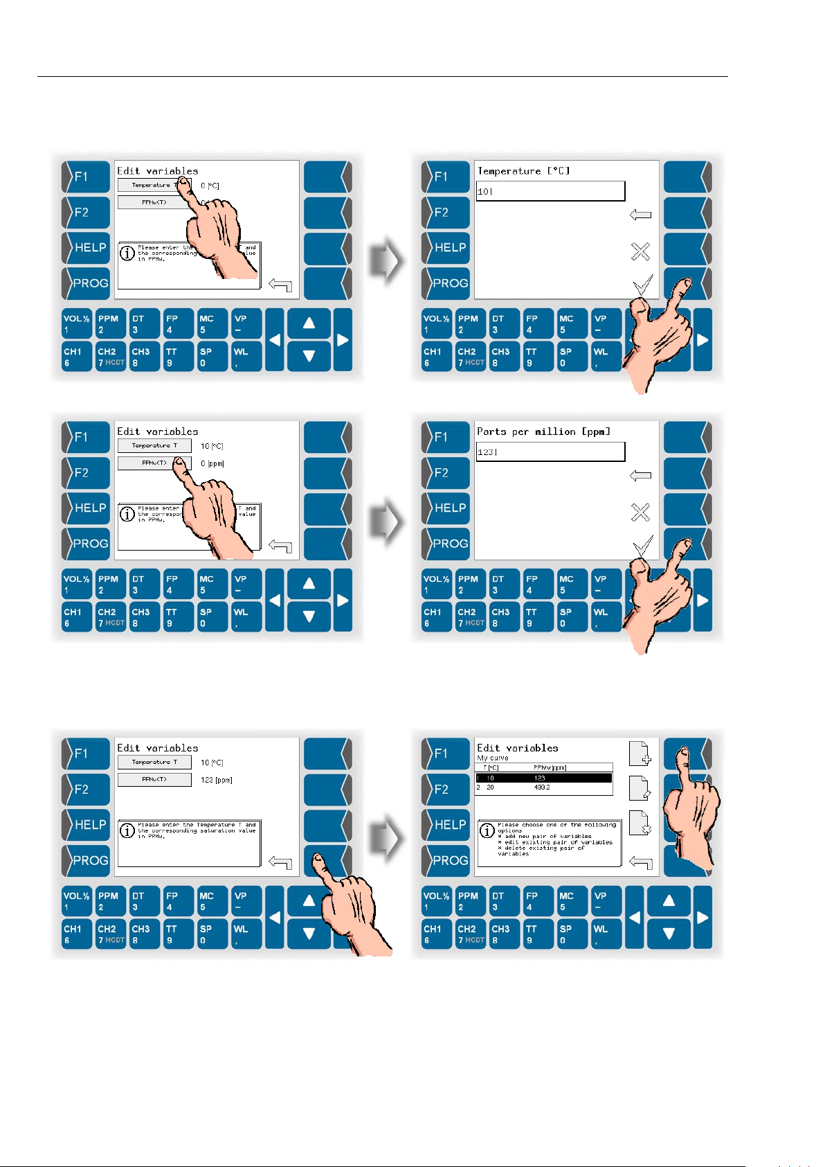
Programming
5-38
● Then enter the measured values for temperature and PPMw.
● Add further points to the curve and enter the pairs of variates as
described.
HYGROPHIL® F 5673 Operating manual, Software version 1.8.x, 387896MDHEN(14.06.2013)
 Loading...