


Directions for use |
|
|
Istruzioni per l'uso |
|
|
Instrucciones de manejo |
|
|
Mode d’emploi |
|
|
Bedienungsanleitung |
|
|
Instruções de utilização |
|
|
Gebruiksaanwijzingen |
40070 |
40080 |
60050 |
70060 |
70076 |
80060 |
90060 |
900114 |
40070 / 40080 / 60050 / 70060 / 70076 / 80060 / 90060 / 900114
60050
15
10
14
12
13
16 18
1
2
3
70060 / 80060
12 |
9 |
15
10
14
17
13
16 18
3
1
2
4

70076
15
13 |
|
17 |
|
14 |
|
18 |
12 |
|
10
9
3
1
2
5
90060 |
|
|
|
|
|
|
9 |
|
|
|
|
|
|
|
12 |
15 |
14 |
|
|
|
|
|
|
|
|
|
|
10 |
|
|
|
17 |
|
13 |
|
|
|
|
|
|
|
N |
25 |
|
|
|
|
|
21 |
|
|
|
|
|
|
|
|
|
|
|
|
|
|
4 |
|
19 |
|
18 |
16 |
|
|
|
|
|
||
|
|
|
|
|
|
S |
|
5 |
|
|
|
|
|
|
6 |
|
|
|
|
1 |
|
|
|
|
|
|
|
|
|
|
3 |
|
|
|
|
|
2 |
|
|
|
|
|
Fig. 8 |
|
|
|
|
|
6
900114 |
|
|
|
|
|
|
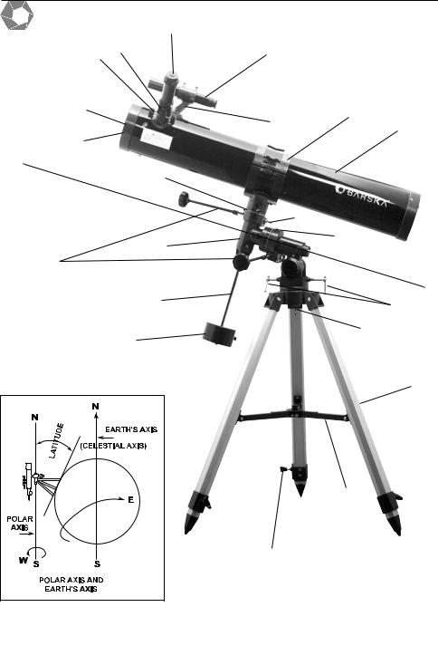
13 |
|
|
18 |
17 |
|
15 |
|
|
|
|
||
10 |
|
|
|
11 |
|
|
|
14 |
|
|
|
|
12 |
|
|
|
|
|
|
9 |
|
|
|
|
N |
|
|
|
|
|
|
25 |
|
|
|
|
|
|
24 |
|
|
4 |
|
23 |
|
|
|
|
|
19 |
|
|
|
21 |
|
|
|
|
|
|
|
5 |
|
S |
|
|
|
20 |
|
|
|
|
|
|
|
|
6 |
|
22 |
|
|
|
|
|
|
|
|
|
1 |
|
|
|
|
3 |
|
|
|
2 |
|
Fig. 8
7

Fig. 1
Fig. 2 |
Fig. 1A |
Fig. 3 |
Fig. 4 |
Fig. 5 |
Fig. 6 |
Fig. 7 |
8 |

Fig. 9 |
|
|
14 |
15 |
|
13 |
|
|
|
|
|
|
17 |
|
|
18 |
|
N |
|
12 |
|
|
|
25 |
|
|
4 |
24 |
|
|
|
|
|
23 |
|
|
20 |
|
5 |
|
|
|
21 |
S |
|
|
|
6 |
22 |
|
|
|
|
|
1 |
|
2 |
3 |
|
|
9 |
|

english
ENGLISH
DIRECTIONS FOR USE
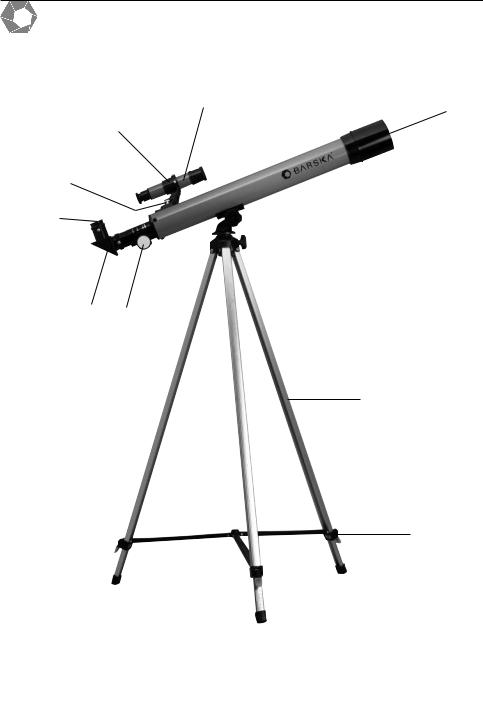
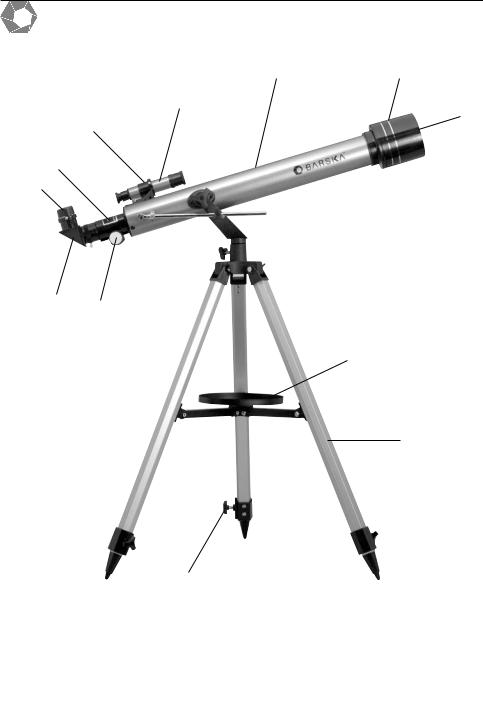
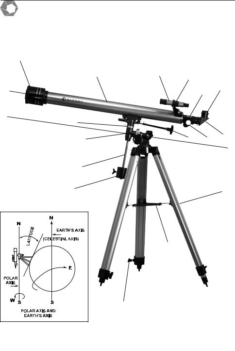
1 |
Tripod Leg |
11 |
Cradle |
2 |
Tripod Leg Adjusting Screw |
12 |
Telescope Main Body |
3 |
Accessory Tray |
13 |
Eyepiece |
4 |
Polar Axis Locking Lever |
14 |
Finderscope Bracket |
5 |
Counterweight Shaft |
15 |
Finderscope |
6 |
Counterweight |
16 |
Diagonal |
7 |
Hour Axis Scale |
17 |
Focus Tube |
8 |
Declination Scale |
18 |
Focus Knob |
9 |
Objective Lens |
19 |
Flexible Control Cable |
10 |
Dust Caps |
20 |
Polar Axis Micro Adjustment Lever |
|
|
|
|
1)Extend the legs (1), as indicated in Fig. 1, and lock them in the adjusted height with the supplied wing nut. Before tightening the wing nuts check that there is a washer underneath.
2)Connect all three tripod legs to the tripod head with the wing nut and screw in the manner as indicated in Fig. 2a).
b)For model 40070 / 40080 & 600X50 proceed as in figure 1A setting up the pre mounted tripod and connecting it to the telescope with the micrometric screw that regulates the movement of the telescope.
3)Now fasten the accessory tray (3) to the flanges of the tripod legs with the supplied screws and wing nuts. (see Fig. 3)
4)After all screws have been firmly tightened, the telescope can be connected to the yoke of the tripod head. Proceed as indicated in Fig. 2 for model 60050 / 70060 / 80060 / 70076
b)Mount the telescope main body (12) in the yoke, and adjust with the large locking screw. Now adjust the pin of the micro adjustable altitude control with the guide provided for this purpose (see Fig. 2 b + c).
c)Model 90060 / 900114 proceed as in Fig. 9.
5)Remove the finder scope (15) with attached bracket (14) from the box. Then remove the two knurled thumb screws from the telescope main body (12). Position the finder scope bracket on the telescope main body so that the holes in the base of the bracket line up with the exposed holes in the telescope main body. Return the two knurled thumb screws and tighten securely (see Fig. 4).
10

6) |
Insert the angle prism into the focusing tube (17). Secure by tightening the correspon- |
english |
7) |
Insert the eyepiece (13) into the angle prism (16). This also has to be adjusted with the |
|
|
ding fastening screws (see Fig. 5.) for model 90060 & 900114 see (Fig. 9). |
|
|
small fastening screw (see Fig. 6). |
|
8) |
If you wish to use the prismatic eyepiece extension with the factor 1.5x or the 3x Barlow |
|
|
lens, insert this between eyepiece (13) and the focusing tube (17) (see Fig. 7). |
|
9) |
If your telescope is supplied with a moon filter you can screw the filter into the thread of |
|
|
the eyepiece underneath before inserting the eyepiece into the focus tube. |
|
USING THE SETTING CIRCLES TO LOCATE STARS (90060 and 900114 only)
Since this equatorial telescope is designed to move in any direction, it can be set to track the apparent movements of celestial bodies across the sky. This movement of celestial bodies is in the direction opposite to that of the earth's rotation and is around the earth's axis or celestial axis (Fig. 8). By simply aiming the telescope polar axis (21) at celestial North you will automatically place the telescope in parallel with the earth's axis and thus be able to locate stars in the sky based on information in star charts and star atlases. In simple language you aim your telescope in the center of the celestial sphere that point in the sky (like the hub of a wheel) and does not appear to move. The angle of declination is simply 900 minus the angle away from this hub. Celestial North is 90°. If you were at the North Pole, you would point your telescope straight up to aim at celestial North.
To compensate for your position on the round earth, the polar axis (21) is set in one of two simple ways. (see Fig. 8).
1)Set up the telescope at night. Loosen the declination axis clamp lever (24) (Fig. 9) and turn the telescope around until the arrow points at 90° on the declination scale. Tighten the declination clamp lever. The telescope is now in parallel with the polar axis.
2)Loosen the horizontal lever (22) (Fig. 9) and turn the telescope until the OPEN end faces due North. This can be done by an approximate sighting on the Pole Star (Polaris) or by the use of a compass to find magnetic north.
True North is then found by directing the telescope at the Pole Star, as magnetic North is slightly away from the true North.
3)Look up the latitude of your area from a geographical atlas. Loosen the polar axis lever (20) (Fig. 9) and set the latitude scale (23) (Fig. 9) to the correct latitude for your area. Aim the sighting scope at the Pole Star. You will probably notice that Polaris (the Pole Star) is not in the center of the crosshair finder scope. This is probably because your telescope is not on even ground level.
Loosen the horizontal axis lever (22) again and turn the telescope so that it is directly aimed at the Pole Star. Clamp both levers tight. Polaris is 1° off the North celestial pole. Therefore, the sighting of stars will have to be slightly adjusted as you locate them in the heavens.
11
english
ADJUSTING THE FINDERSCOPE
Since the telescope has a limited field of view, it can be quite difficult to locate a given star or planet. For this reason the telescope is fitted with a finder scope with reticule for orientation. It is advisable to complete the following settings in daylight.
1)Insert the eyepiece with the lowest magnification in the Zenith mirror or Zenith prism. Look at a stationary easily recognizable object that is not further away than 300m. Turn the telescope with the horizontal axle, and move the vertical axle until the object is in the middle of the field of view, and then focus the image. Tighten the adjusting screw on the mount so that the telescope remains in this position (the higher the object is above the horizon, the easier it is to locate).
2)Now look through the finder scope. lf the object seen through the telescope is not visible, then release the adjusting screws and move the finder scope until the object can be seen. Now retighten the adjusting screw while ensuring that the object remains visible in the centre or the finder scope. To simplify this procedure use the adjusting screws to adjust the object in the centre. The finder scope will move in the direction of the screw in which it is being turned. All screws can be finally tightened as soon as the setting with the eyepiece coincides with that of the finder scope.
PAN HEAD MOUNT 60050 & 40070 & 40080
The telescope is fitted with a pan head mount. The movement of the telescope is done by movements whilst turning the main bolt.
AZIMUTH MOUNT 70060 & 80060 & 70076
The telescope is fitted with an Altitude - Azimuth mount. "Altitude" refers to the up and down or vertical movement of the telescope, whilst " Azimuth" refers to the sideways or horizontal movement.
EQUATORIAL MOUNT 90060 & 900114
The Equatorial mount, in conjunction with the micro adjustable Altitude control, and the Azimuth Lock enables you to observe the entire night sky, or any celestial body, without having to move the tripod.
WHICH MAGNIFICATION? SELECTING THE CORRRECT EYEPIECE
Magnification defines the power of a telescope to enlarge an image or to 'pull it in' closer for viewing.
Example :
700mm focal length |
|
= 56 x magnification |
12.5mm focal length of eyepiece |
|
|
The required magnification depends upon the object being observed. The following general guideline is recommended for this purpose: Ideal viewing conditions are obtained if the magnification is not more than 15x - 20x the diameter of the objective lens, i.e. an optimal
12

magnification of 100x -125x can be expected with 60 mm diameter objective lens to observe most celestial objects. A lower magnification power is advisable for the observation of stars.
The field of view is wider so that the object for observation is more easily localized. The highest magnification power should only be used for particularly clear observations of the moon an object that is relatively close and exceptionally bright, so that good detail resolution is achieved at high magnification ratios.
BARLOW LENS
The Barlow lens increases the magnification of the telescope. A 3x Barlow lens will therefore triple the telescope's magnification power. Consequently a 56x magnification can be tripled to 168x with a 3x Barlow lens. The highest magnification power of the Barlow lens should only be used for large and bright objects such as the moon and the brightest planets, as well as for nights with optimal observation conditions.
Do not use the Barlow lens and the erecting eyepiece in conjunction with the angle prism as this produces a particularly low resolution level with the result that the image can no longer be sharply focuses. To use the Barlow lens take the angle prism out of the tube. Insert the Barlow lens into the focus tube and then attach the required eyepiece to the Barlow lens, focusing is then completed in the customary manner.
VERY IMPORTANT GENERAL REMARKS
Avoid sudden temperature fluctuations as the moisture in the air will condense on the objective lens. Should this happen, then place the objective lens not too close to a source of heat and allow the moisture to evaporate slowly.
CAUTION
TO AVOID EYE DAMAGE NEVER LOOK THROUGH THE TELESCOPE INTO ANOTHER OPTICAL INSTRUMENT, INTO THE SUN OR A LIGHT SOURCE.
NEVER LEAVE A TELESCOPE UNATTENDED, A CHILD COULD LOOK AT THE SUN WITH IT AND SUFFER PERMANENT EYE DAMAGE.
When mounting the parts ensure that the securing screws are not tightened too firmly. This could damage the parts or the internal thread of the holders with the result that the screws can no longer be tightened!
english
13

english
PARTS & ACCESSORIES
The parts and accessories that come with your telescope might be different from country to country, please refer to the packaging to find out how your telescope is equipped.
The following magnification values are achieved when using the prismatic eyepiece extensions and the exchangeable eyepieces: See technical Chart (p. 45).
BARSKA® OPTICS WARRANTY / REPAIR OUTSIDE THE US & CANADA
Congratulations on your purchase of a high quality product. Your optical device has been manufactured to meet the highest quality standards. To ensure proper usage, please follow the enclosed instructions manual.
This Barska® Optics product is fully guaranteed against any manufacturing defects for 10 years from the date of purchase as long as it has been used under normal conditions. During this period, it is the distributors responsibility in each country to either repair or replace free of charge upon presentation of the original purchase receipt. This warranty is not transferable, will not be reissued and does not cover any damages caused by accident, misuse or unauthorised repair.
For repair service please bring your product back to the point of sale or contact your local distributor which you can locate in the yellow pages or on our website: www.barska.com
All costs to and from the repair centre such as travel, carriage costs, postage, insurance charges etc. are always at the expense of the owner. If the product repair costs are not covered by the warranty, the costs of evaluating the repairs, administrative and carriage costs are at the owners expense and are payable no later than upon delivery. In the event that the repair costs are not accepted by the owner, the owner can either abandon the product free of charge at the repair centre, or recover the non-repaired product by paying the cost for evaluating the repairs, administrative and carriage costs no later than upon delivery. All other claims of any nature are not covered.
BARSKA® OPTICS WARRANTY / REPAIR WITHIN THE US & CANADA
Please refer to the additional warranty insert card
© 2004 Barska® Optics
14

ITALIANO
ISTRUZIONI PER L'USO
1 |
Gamba treppiedi |
11 |
Culla |
2 |
Vite regolazione gambe treppiedi |
12 |
Corpa principale telescopio |
3 |
Scatola porta accessori |
13 |
Oculare |
4 |
Leva fermo asse polare |
14 |
Supporto cercatore |
5 |
Asta contrappeso |
15 |
Cercatore |
6 |
Contrappeso |
16 |
Diagonale |
7 |
Scala asse oraria |
17 |
Manopola fuoco |
8 |
Scala asse deslinazione |
18 |
Tubo di messa a fuoco |
9 |
Lenti objettivo |
19 |
Cavo di controllo flessible |
10 |
Copertureantipoivere |
20 |
Leva di microregolazione asse polare |
|
(toglierle prima di operare) |
|
|
|
|
|
|
1)Estraete dall'imballaggio le gambe del treppiede (1), estendetele alla lunghezza richiesta: poi bloccatele a mezzo delle viti ad alette fornite, così come raffigurato alla Fig. 1. Prima di stringerle, non dimenticate di interporre una rondella sotto ciascuna vite ad alette.
2)Assemblate le tre gambe sulla testa del treppiede a mezzo delle viti e dei dadi ad alette come raffigurato alla Fig. 2a).
b)Per i modelli 40070 / 40080 e 60050 procedete come nella figura 1A installando il treppiede premontato e collegandolo al telescopio per mezzo della vite micrometrica che regola il movimento del telescopio.
3)Fissate successivamente il piatto porta accessori (3) alle flange d'appoggio delle gambe utilizzando le viti fornite e i dadi ad alette (vedi Fig. 3).
4)Quando tutti i dadi e le viti sono stretti, il telescopio può essere montato nella sua forca di testa del treppiede come rappresentato alla Fig. 2 per il modello 60050 / 70060 / 80060 / 70076.
b)Montate il corpo principale del telescopio (12) nella forca e fissatelo con la grande vite di bloccaggio. Assemblate quindi l'asta del comando ascensionale con la guida fornita a questo fine (vedi Fig. 2b + c).
c)Per i modelli 90060/900114 procedete come nella Fig. 9A.
5)Rimuovete dall'imballo il piccolo cannocchiale cercatore (15) montato sulla sua staffa (14). Rimuovete le due viti zigrinate del cercatore astronomico e posizionate il cercatore in modo che i due buchi nella base vengano a coincidere con i fori che venite a liberare togliendo le viti. Rimettete allora al loro posto le due viti zigrinate e serratele per fissare il cercatore. (vedi Fig. 4).
italiano
15
 Loading...