

Barnes & Noble BP27A, BP27D, BP27HT, BP27 User Manual
®
Manual Index
MENU
HOME
DISCONTINUED
Parts may
NOT be available
BARNES
INSTALLATION and OPERATION MANUAL
Submersible Sump Pump
SERIES: BP27, BP27A, BP27D,
& BP27HT
Standard & High Temperature
1/3 HP, 1550 RPM
IMPORTANT: Read all instructions in this manual before operating pump.
A Crane Co. Company
As a result of Crane Pumps & Systems, Inc., constant product improvement program, product
changes may occur. As such Crane Pumps & Systems, Inc., reserves the right to change product
without prior written notification.
PUMPS & SYSTEMS
420 Third Street/P.O. Box 603 83 West Drive, Brampton
Piqua, Ohio 45356-0603 Ontario, Canada L6T 2J6
Phone: (937) 778-8947 Phone: (905) 457-6223
Fax: (937) 773-7157 Fax: (905) 457-2650
www.cranepumps.com
Form No. 068910-Rev. E

TABLE OF CONTENTS
Manual Index
HOME
MENU
WAR NING AND S AFETY PREC AUTION S .... .... .................................................................. 3
A. PUMP SPECIFICATIONS ..... ..... .... .... ..... .... ..... .................................................................... 4
B. GENERAL INFORMATION ..... ..... .... ..... .... ..... .... .... ..... .... ..... ................................................ 5
C. INSTALLATION ... ..... .... ..... .... ..... .... .... ..... .... ..... .... ..... .... .......................................................5 - 6
D. SERVIC E AND REPAIR .... .... ..... .... .... ..... .... ..... .... ..... .... .... ..... .... .......................................... 6 - 8
E. REPLACEME NT PARTS .................. ..... .... ..... .... .... ..... .... ..... .... ..... .... .... ..... .......................... 12
TROUBLE SHOOTING ..... .... ..... .... .................................................................................. .... 9
EXPLODED VIEW (Fig. 4)... .... ..... .... ..... .... ..... ...................................................................... 11
PARTS LIST ........................................................................... .... ..... .... ..... .... ..... .... .... ..... .... .. 12
WAR RANTY INFORMATI ON ............................................................................ .... .... ..... .... .. 13
WARRANTY
WARRANTY REGISTRATION
Other brand and product names are trademarks or registered trademarks of their respective holders.
® Barnes is a registered trademark of Barnes Pumps, Inc.
© Barnes Pumps, Inc. 1994, 1997, 1998, 1999, 2002 Alteration Rights Reserved. Printed in U.S.A.
2
SAFETY FIRST!
Manual Index
HOME
MENU
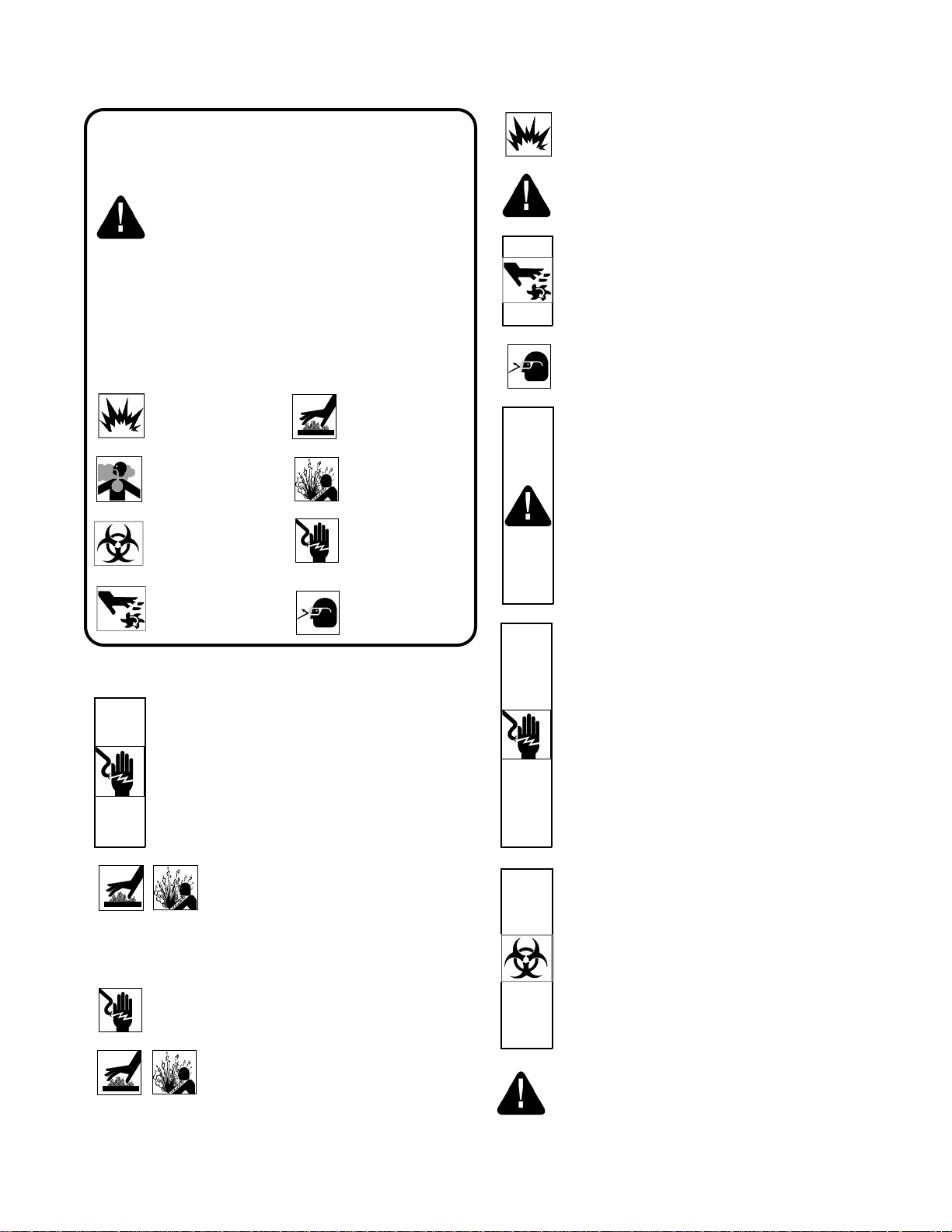
Please Read This Before Installing Or Operating Pump. This
information is provided for SAFETY and to PREVENT EQUIPMENT
PROBLEMS. To help recognize this information, observe the
following symbols:
IMPORTAN T! Warns about hazards that can result in
personal injury or Indicates factors concerned with
assembly, installation, operation, or maintenance which
could result in damage to the machine or equipment if ignored.
CAUTION ! Warns about hazards that can or will cause minor
personal injury or property damage if ignored. Used with symbols
below.
WARNING ! Warns about hazards that can or will cause serious
personal injury, death, or major property damage if ignored. Used
with symbols below.
Hazardous fluids can
cause fire or explosions,
burns or death could result.
Toxic Fumes Breathing can cause
nausea, fainting or death.
Biohazard can cause
serious personal injury.
Extrem ely hot Severe burns can
occur on contact.
Hazardous pressure
Eruptions or explosions
could cause personal
injury or property damage
Hazardous voltage can
shock, burn or cause
death.
WARNIN G ! Do not pump hazardous materials
(flammable, caustic, etc.) unless the pump is
specifically designed and designated to handle them.
CAUTION ! Do not block or restrict discharge hose,
as discharge hose may whip under pressure.
WARNING ! Do not wear loose clothing that may
become entangled in moving parts.
WARNING ! Keep clear of suction and discharge
openings. DO NOT insert fingers in pump with
power connected.
Always wear eye protection when working on pumps.
Make sure lifting handles are securely fastened each
time before lifting. DO NOT operate pump without safety
devices in place. Always replace safety devices that
have been removed during service or repair. Secure the
pump in its operating position so it can not tip over, fall
or slide.
DO NOT exceed manufacturers recommendation for
maximum performance, as this could cause the motor
to overheat.
Rotating machinery
Only qualified personnel should install, operate and repair pump. Any
wiring of pumps should be performed by a qualified electrician.
and self priming pump the heat build may cause the generation of
steam with resulting dangerous pressures. It is recommended that
a high case temperature switch or pressure relief valve be installed
on the pump body.
Amputation or severe
laceration can result.
WARNING ! To reduce risk of electrical shock, pumps and
control panels must be properly grounded in accordance
with the National Electric Code (NEC) or the Canadian
Electrical Code (CEC) and all applicable state, province,
local codes and ordinances. Improper grounding voids
warranty
WARNING ! To reduce risk of electrical shock, always
disconnect the pump from the power source before
handling or servicing. Lock out power and tag.
WARNING ! Operation aga inst a closed
discharge valve will cause premature bearing
and seal failure on any pump, and on end suction
CAUTION ! Never operate a pump with a plug-in
type power cord without a ground fault
circuit interrupter.
CAUTION ! Pumps build up heat and pressure
during operation-allow time for pumps to cool
before handling or servicing.
Eye protection
required
DO NOT remove cord and strain relief. DO NOT connect
conduit to pump.
WARNING ! Cable should be protected at all times to
avoid punctures, cut, bruises and abrasions. Inspect
frequently. Never handle connected power cords with
wet hands.
WARNING ! To reduce risk of electrical shock, all
wiring and junction connections should be made per
the NEC or CEC and applicable state or province and
local codes. Requirements may vary depending on
usage and location.
WARNING ! Submersible Pumps are not approved for
use in swimming pools, recreational water installations
decorative fountains or any installation where human
contact with the pumped fluid is common.
WA RNIN G ! Products returned must be cleaned,
sanitized, or decontaminated as necessary prior to
shipment, to insure that employees will not be exposed to
health hazards in handling said material. All Applicable
Laws And Regulations Shall Apply.
Bronze/brass and bronze/brass fitted pumps may contain
lead levels higher than considered safe for potable water
systems. Various government agencies have determined
that leaded copper alloys should not be used in
potable water applications. For non-leaded copper
alloy materials of construction, please contact factory.
BARNES® Pumps, Inc. is not responsible for losses, injury,
or death resulting from a failure to observe these safety
precautions, misuse or abuse of pumps or equipment.
3
SECTION: A- PUMP SPECIFICATIONS
Manual Index
HOME
MENU
DISCHARGE: 1-1/2", (38) N.P.T. Female, Vertical.
LIQUID TEMPERATURE:
Standard: 104°F (40°C) Continuous.
High Temp: 200°F (93°C) Continuous.
MOTOR HOUSING: Cast Iron ASTM A-48, Class 20 Min.
PUMP BODY:
BP27, A, D & HT Cast Iron ASTM A-48, Class 20 Min.
STRAINER:Standard: Polypropylene, .50 x .50 Slot Size
High Temp: Brass .22 x .22 Slot Size
IMPELLER: Design: 5 Vane, Open.
Material: Polypropylene.
SHAFT: Steel
SQUARE RINGS: Buna-N
HARDWARE: 300 Series Stainless Steel
PAINT: Air Dry Water Soluble Enamel
CABLE ENTRY: 10 ft. (25mm) Cord with Plug and
Pressure Grommet for Sealing and
Strain Relief.
BP27A,
BP27,
(Less Float)
BP27HT
with or without Float
* Factory Set, Adjustable.
SEAL: Design: Single Mechanical, Oil-Filled
Reservoir.
Material: Rotating Faces - Ceramic
Stationary Faces - Carbon
Elastomer - Buna-N
Hardware - 300 Series Stainless
SPEED: 1550 RPM
LOWER BEARING:
Design: Sleeve
MOTOR: Design: Oil-Filled.
Insulation: Class A.
SINGLE PHASE: Shaded Pole. Includes Overload
Protection in Motor.
FLOAT: BP27 : None
BP27A: Wide Angle, Mechanical, 10ft Cable,
With Piggy-Back Plug.
BP27D: Diaphragm w/Piggy-Back Plug.
BP27HT Float Supplied seperately.
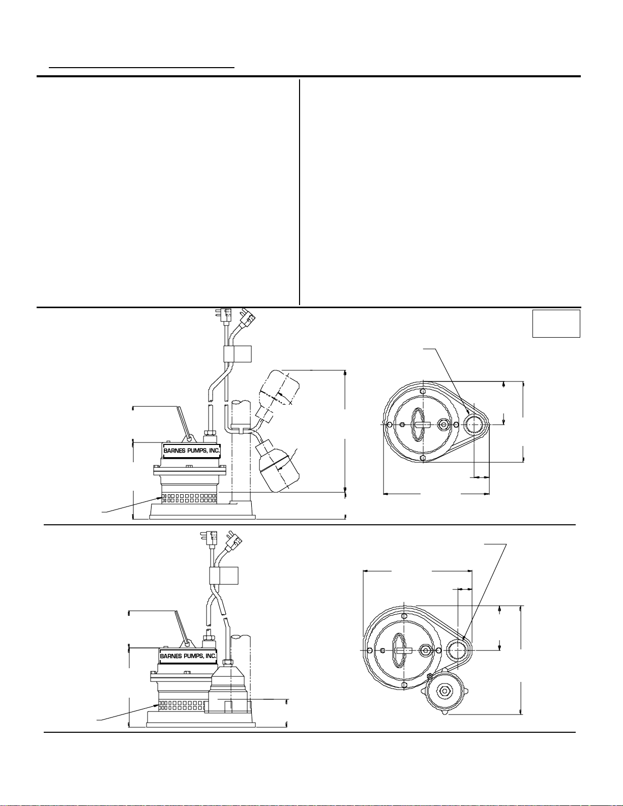
MINIMUM SUMP DIA: 18" (457mm)
inches
(mm)
1.50 (38) NPT
DISCHARGE
SUCTION
BP27D
3.25
(83)
6.75
(172)
3.25
(83)
6.75
(172)
120°
Pumping
Differential
*9.00
(229)
2.25 (57)
3.89
(99)
7.29
(185)
1.32 (34)
9.55
(243)
1.50 (38) NPT
DISCHARGE
9.55
(243)
1.32 (34)
3.89
(99)
9.90
(252)
SUCTION
2.25 (57)
4

SECTION B: GENERAL INFORMATION
Manual Index
HOME
MENU
SECTION C: INSTALLATION
B-1) To the Purchaser:
Congratulations! You are the owner of one of the finest
pumps on the market today. Barnes
engineered and manufactured of high quality components.
Over one hundred years of pump building experience
along with a continuing quality assurance program
combine to produce a pump which will stand up to the
toughest applications.
This Barnes Pumps, Inc. manual will provide helpful
information concerning installation, maintenance, and
proper service guidelines. Check local codes and
requirements before installation. Servicing should be
performed by knowledgeable pump service contractors or
authorized service stations.
The pump is packaged ready for installation and no
connections or adjustments are necessary except for
attaching discharge piping and plugging in service cord.
B-2) Receiving
Upon receiving the pump, it should be inspected for
damage or shortages. If damage has occurred, file a claim
immediately with the company that delivered the pump. If
the manual is removed from the crating, do not lose or
misplace.
B-3) Storage:
Short Term- Barnes Pumps are manufactured for efficient
performance following long inoperative periods in storage.
For best results, pumps can be retained in storage, as
factory assembled, in a dry atmosphere with constant
temperatures for up to six (6) months.
®
Pumps are products
C-1) Location:
These pumping units are self-contained and are
recommended for use in a sump or basin. This pump is
designed to pump rain water or light effluent, nonexplosive
and noncorrosive liquids and shall NOT be installed in
locations classified as hazardous in accordance with the
National Electrical Code (NEC), ANSI/NFPA 70 or the
Canadian Electrical Code (CEC). The sump or basin shall
be vented in accordance with local plumbing codes.
Provide proper sump diameter of approx. 18" (457mm)
minimum and depth of approx. 20" (508mm) minimum to
allow the pump and switch to operate without restriction.
The float switch should not come in contact with side or
bottom of sump. Make sure sump is free of string, cloth,
nails, gravel, etc. before installing pump. Never install the
pump in a trench, ditch, or hole with a dirt bottom where
the suction will become plugged.
C-1.1) Submergence:
The minimum sump liquid level should never be less than
2.5 inches (64mm) above the pump bottom.
C-2) Discharge:
Discharge piping should be as short as possible. The
installation of a check valve in the discharge piping is
recommended for each pump being used. The check valve
is used to prevent backflow into the sump. Excessive
backflow can cause flooding and/or damage to the pump.
C-3) Liquid Level Controls
Figure 2 shows a typical installation for any submersible
pump using a level control mounted to the discharge piping
with a piggy-back plug.
Long Term- Any length of time exceeding six (6) months,
but not more than twenty four (24) months. The units
should be stored in a temperature controlled area, a roofed
over walled enclosure that provides protection from the
elements (rain, snow, wind blown dust, etc..), and whose
temperature can be maintained between +40 deg. F and
+120 deg. F.
Pump should be stored in its original shipping container
and on initial start up, rotate impeller by hand to assure
seal and impeller rotate freely.
B-4) SERVICE CENTERS:
For the location of the nearest Barnes Pumps Service
Center, check your catalog, your Barnes Pumps, Inc.
representative or Barnes Pumps, Inc. Service Department
in Piqua, Ohio, telephone (937) 77808947 or Crane
Pumps & Systems Canada Inc., in Bramton, Ontario
(905) 457-6223.
General Comments:
1) Never work in the sump with the power on.
2) Level controls are factory set for a pumping differential
of 9 inches. If that is the cycle desired, simply circle the
discharge pipe with the pipe mounting strap, feed the end
through the worm drive, and tighten with a screwdriver. Be
certain that the level control cannot hang up or foul in it’s
swing. Also, make certain the pump impeller is still
submerged when the level control is in the ’off’ mode.
3) If a higher pump differential is needed, grip the cord near
the neck of the float, then using the other hand, exert a
steady force on the lower edge of the cable clamp. The
cable clamp should slide up to the new pivot point. Attach
the level control to the discharge pipe in the manner
described above.
5
 Loading...