

Page 1

IPAM 400
Preliminary Development Specification
Advanced, multi format IP audio module with network, USB and serial
interfaces plus Wi-Fi, adding IP based streaming and controlling
capabilities to OEM products
Document version 02.20
Release date 9th April 2018
Hardware Rev. HW 12
© 2017 Barix AG, all rights reserved. All information is subject to change without notice.
All mentioned trademarks belong to their respective owners and are used for reference only
Page 2

Preliminary Development – BARIX IP AUDIO MODULE 400 – V 02.20 – 9.April.2018
Table of contents 2
Table of Con tents
TABLE OF CONTENTS 2
INTRODUCTION 4
About this document 4
Additional documents 4
About the IP AUDIO MODULE 400 4
Hardware features 4
Evaluation of the Barix IP Audio Module 4
Basic Support Package (BSP) Yocto layer 5
HARDWARE 6
Mechanical drawing 6
Block diagram 7
Network interfaces 7
Serial interfaces 7
Digital audio 7
Analog audio 8
Power supply 8
Peripheral I/O 8
CONNECTORS 9
Connector placement 9
Connector pin out 9
J1 pin out (analog audio input and output) 9
J2 pin out (GPIO, UART, USB, I2C) 9
J4 pin out (network, USB) 10
J5 pin out (I2S output) 10
LAYOUT GUIDELINES 11
General rules 11
Carrier PCB Power and Signal Domains 12
TECHNICAL DATA 13
Power supply input 13
CPUs / Boot / Memory 13
Network interfaces 13
Page 3

Preliminary Development – BARIX IP AUDIO MODULE 400 – V 02.20 – 9.April.2018
Table of contents 3
Serial interfaces 13
Peripheral I/O interfaces 13
Audio interfaces 13
Audio Processor (Codec) Decoding features 13
Line Input and A/D Conversion typical values 14
Microphone input and A/D conversion typical values 14
Line output and D/A conversion typical values 14
Mechanical 14
Dimensions 14
Weight 14
MTBF calculations 15
Environmental 15
Core frequency versus Temperature variation 15
Certifications / Compliances 16
ORDERING INFORMATION 17
Page 4
Preliminary Development – BARIX IP AUDIO MODULE 400 – V 02.20 – 9.April.2018
Introduction 4
In trodu c tion
About this
document
This Development Specification aims at giving insight to detailed
technical aspects of the Barix IP AUDIO MODULE 400 (IPAM400) and
complements the information given in the product sheet.
Additional
documents
As several different Linux OS based images and packages can be used
with the Barix IP AUDIO MODULE 400, the process of loading or
updating software is covered in individual documents.
For information about the loading and configuration of the loaded
firmware please refer to the corresponding software user manual and
firmware technical documentation.
About the IP
AUDIO MODULE
400
The IP AUDIO MODULE 400 enables manufacturers of traditional audio
devices to add network capabilities to their products as well as develop
IP streaming devices.
Hardware
features
The Barix IP AUDIO MODULE 400 features:
• Stereo line input and output, 0dBuStereo Line in and outputs
• Microphone input (coil, powered or passive capacitive,
balanced or unbalanced)
• I2S input and output (192k capable)
• Integrated SoC with ARM Cortex quad core CPU
• 10/100/100Mbit Ethernet port (with PHY)
• SD/TF card slot
• 16MB SPI Flash
• TTL level UART
• USB2.0 OTG interface, two USB2.0 Host
• Dallas 1-wire interface (e.g. for Real Time Clock)
• 7 GPIOs
• Small form factor
• Low Power consumption, runs off a single +3.3Volt DC
power source
• 2 mounting holes (0.106”/2.7mm) for fixation of IP Audio
Module
Evaluation of the
Barix IP Audio
Module
Barix recommends the IPAM evaluation board based on Annucicom 60
for evaluation purposes prior to development of an own carrier board.
Page 5

Preliminary Development – BARIX IP AUDIO MODULE 400 – V 02.20 – 9.April.2018
Introduction 5
Basic Support
Package (BSP)
Yocto layer
The BARIX IPAM400 can be used for developing multiple applications
related to networked audio distribution, playback and control.
BARIX provides an embedded Linux system based on the Yocto
framework and the associated Yocto layer that contains the board's
Basic Support Package (BSP) for the IPAM400.
This Yocto layer can be used as a base platform to develop all kind of
applications on top of it.
The provided BSP Yocto layer includes:
· Definitions for the "barix-ipam400" machine
· U-Boot boot loader
· Linux Kernel 4.x
· A default Linux Kernel device tree and Kernel configuration
· Secure Firmware update mechanism featuring a dual root file
system strategy and a recovery mechanism
· Definition for a base SW image
· Scripts to create and install SW images and SW updates
All these functionalities are configurable and adaptable to the
developer's needs.
Developers can use the BSP to generate the toolchain that enables the
development of any application.
The BSP package is a starting point and can be easily extended by
creating or adding Yocto layers that allow developers to quickly add
more applications and libraries to completely customize the software
and to create new SW images.
The common feature set includes:
• Embedded and robust operating system with IPv4/IPv6 IP stack
• IP standard based protocols (TCP/IP, UDP, HTTP, ICMP, SNMP)
• OEM Software development by BARIX on request
• High quality, multi standard audio encoding and decoding can be
implemented in software:
• G.711, G.722, PCM linear, Ogg Vorbis, MP3, AAC+, FLAC
• Acoustic echo cancellation (AEC)
Page 6
Preliminary Development – BARIX IP AUDIO MODULE 400 – V 02.20 – 9.April.2018
Hardware 6
Hardwa re
Mechanical drawing
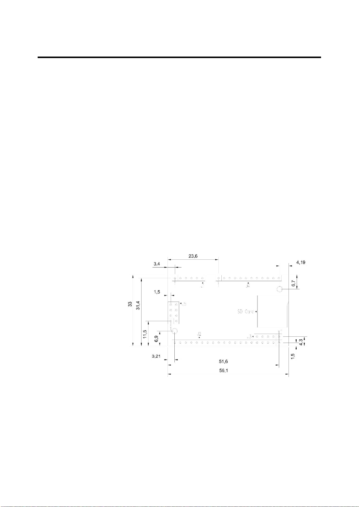
The Barix IP AUDIO MODULE 400 provides five, standard 2,54mm
spacing, single row pin headers, intended to match target connector or
motherboard, also suitable to soldering.
For mechanical fixation, the board provides two 2.7mm mounting holes
for 2.5mm screws.
The total size is 56.1mm +/-0.2 by 33.0mm +/-0.2.
Maximum component height is 5.6mm. Using standard distance bolts of
6mm a total height of 9mm above the carrier board can be achieved
when mounted on a carrier board by means of soldering the pin headers
into holes of the carrier board directly.
Using single row female headers (counterpart to pin headers) the height
will increase and must be measured by the integrator (our experience in
production shows a minimal height of 11.5mm above the carrier board
without using distance bolts and 12mm using 9mm distance bolts).
Although the total height is increased, the advantage of being able to
replace a module should be considered.
The above drawing shows the component side which faces down onto
the carrier PCB.
Dimensions are metric (mm)
Drawing is not to scale
Tolerance of PCB dimension is +-0.2mm, others 0.1mm
Page 7
Preliminary Development – BARIX IP AUDIO MODULE 400 – V 02.20 – 9.April.2018
Hardware 7
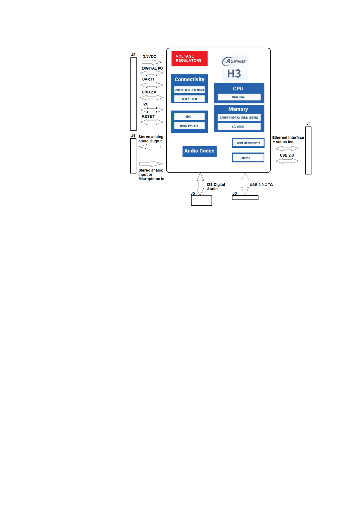
Block diagram
Network interfaces
1 x PHY (TP), 2 ETH Status LEDs
The Barix IP AUDIO MODULE 400 is equipped with one physical layer
(PHY) Ethernet interface (10/100MBit, full / half duplex, autonegotiation).
Two Ethernet status LEDs can be controlled.
Serial interfaces
2 x UART (TTL level), 1 x USB 2.0 OTG and 2 x USB 2.0 Host
The serial port UART0 can be used to build serial standard interfaces
like RS-232 or RS-485 by attaching external driver chips. Flow control
signals are available for that UART. The second UART shares its
function with IO pins and is Tx/Rx only.
One USB 2.0 On-the-Go and 2 x USB 2.0 Host interfaces supporting
High-Speed (HS,480Mbps), Full-Speed(FS,12Mbps) and LowSpeed(LS,1.5Mbps) in host mode. It complies with EHCI v1.0 and OHCI
v1.0a.
Digital audio
I2S (Inter-IC Sound)
The I2S interface can be used to connect with I2S capable devices.
Page 8

Preliminary Development – BARIX IP AUDIO MODULE 400 – V 02.20 – 9.April.2018
Hardware 8
Analog audio
1 x Stereo Output (L&R), 1 x Microphone Input
(balanced/unbalanced) or 1 x Stereo Input
Three analog audio interfaces are provided on the Barix IP Audio
Module of which two can be used concurrently (audio input can be
selected to be either stereo input or microphone input).
The stereo output can be used to connect to analog amplifiers. The
stereo inputs allow for the connection of analog audio sources with Line
level outputs.
The microphone (differential inputs, self-biasing) supports the use of a
wide selection of microphones (dynamic, capacitive, FET amplified). The
positive microphone input pin is shared with the left line input so either
Mic or Line In can be selected.
The SoC provides some level adjustment in software both input and
output work with nominal 0dBu audio level.
Power supply
1 x VIN, 8 x DGND, 1 x AGND
One connector with pins is provided to power the Barix IP Audio Module
from a single +3.3 Volt DC power source. Several ground pins are
implemented. It is common practice to connect them all to the ground
plate.
A separate ground domain for the analog part needs to be connected
via separate ground pin.
Max. power consumption of the IPAM 400 is 4 Watts
A separate ground is provided for the audio interfaces.
Peripheral I/O
6 x GPIO
Of the seven 3.3VDC digital general purpose I/Os available on the IP
AUDIO MODULE 400 three can be used freely by OEM software as
either input or output while four I/Os are reserved for designated
functions (see below). When configured as input (default) the I/O is
internally pulled up to 3.3 VDC.
Reserved functions:
• Two I/O pins serve as a user interface for driving status LEDs (green
and red)
• One I/O it is used to control power on of the amplifier
IO/IR-in/RXD3
B
GPIO# PA14, Infrared input, UART_3 data receive
D0-REL
B
GPIO#PA10
IO/TXD3
B
GPIO#PA13 / UART_3 data transmit
IO/RTS3
B
GPIO#PA15 / UART_3 flow control output
IO/CTS3
B
GPIO#PA16 / UART_3 flow control input
OWA_OUT
B
GPIO#PA17 / OWA( One Wire Audio); SPDIF interface.
Page 9

Preliminary Development – BARIX IP AUDIO MODULE 400 – V 02.20 – 9.April.2018
Connectors 9
Connec tors
Connector placement
For connector placement (and type) please refer to the mechanical
drawing in previous chapter.
Connector pin out
J1 pin out (analog audio
input and output)
Pin #
Name
Type
Description (usage)
1
MICIN1N
AI
Mic balanced negative input (unbal. Mic / line: connect
1uF to GND)
2
MICIN1P
AI
Mic positive input or Left channel audio input (for line
see remark above)
3
AGND
P
Audio Ground
4
INR
AI
Right channel audio input
5
LINEOUTL
AO
Left channel audio output
6
LINEOUTR
AO
Right channel audio output
Type: AI=Audio Input, AG=Audio Ground (centrally connected to DGND), AO=Audio Output
Connector pin out
J2 pin out (GPIO, UART,
USB, I2C)
Connector pin out
J3 pin out (USB OTG, Host)
Pin #
Name
Type
Description (usage)
1
-RST
D
Active low Reset I/O (Hardware reset from
power surveillance)
2
IO/IR-in/RXD3
B
GPIO# PA14, Infrared input, UART_3 data
receive, second amplifier shutdown
3
DGND
P
Digital Ground
4
D0-REL
B
GPIO#PA10
5
IO/TXD3
B
GPIO#PA13 / UART_3 data transmit
6
IO/RTS3
B
GPIO#PA15 / UART_3 flow control output
7
IO/CTS3
B
GPIO#PA16 / UART_3 flow control input
8
OWA_OUT
B
GPIO#PA17 / OWA(One Wire
Audio);complies with SPDIF interface
9
Recovery
B
VCC_IO_EN (Button for Reset/Factory
defaults/Bootloader)
10
DGND
P
Digital Ground
11
VIN P Audio module input Voltage 3.3 VDC
12
CTS1
I
UART_1 flow control input
13
RTS1
O
UART_1 flow control output
14
RXD1
I
UART_1 data receive
15
TXD1
O
UART_1 data transmit
16
DGND
P
Digital Ground
17
USBDM1
B
USB 2.0 Host Interface negative
18
USBDP1
B
USB 2.0 Host Interface positive
19
TWI0-SCK
B
GPIO#PA11 /I²C Clock (Connected internally /
Internal testing only)
20
TWI0-DA
B
GPIO#PA12 /I²C Data (Connected internally /
Internal testing only)
Type: O=Output, I=Input, P=Power, B=bidirectional, D = Open Drain (pull-up resistor on
module)
Page 10

Preliminary Development – BARIX IP AUDIO MODULE 400 – V 02.20 – 9.April.2018
Connectors 10
Pin #
Name
Type
Description (usage)
1
Reserved
2
USB-IDDET
I
USB ID detection
3
DGND
P
Digital Ground
4
USBDM0
B
USB 2.0 Host Interface negative / USB 2.0 OTG
Interface negative
5
USBDP0
B
USB 2.0 Host positive negative / USB 2.0 OTG
Interface positive
Type: O=Output, I=Input, P=Power, R = Reference level
Connector pin out
J4 pin out (network, USB)
Pin #
Name
Type
Description (usage)
1
EPHY-TXP
O
Transceiver positive output
2
TCT R Transmit Transformer center Tap
3
EPHY-TXN
O
Transceiver negative output
4
DGND
P
Digital Ground
5
EPHY-RXN
I
Transceiver negative input
6
RCT R Receive Transformer center Tap
7
EPHY-RXP
I
Transceiver positive input
8
DGND
P
Digital Ground
9
USBDM2
B
USB 2.0 Host Interface negative
10
EPHY-SPD-LED
O
Ethernet 10/100M indicator LED
11
EPHY-LINK-LED
O
Ethernet LINK up/down LED
12
USBDP2
B
USB 2.0 Host Interface positive
Type: O=Output, I=Input, P=Power, R = Reference level
Connector pin out
J5 pin out (I2S output)
Pin #
Name
Type
Description (usage)
1
PCM0_CLK
O
I²S serial clock output
2
PCM0_DO
O
I²S serial data output
3
PCM0_SYNC
O
I²S frame indication
4
DGND
P
Digital Ground
5
Reserved
6
X24MO
O
Clock Output 24MHz Crystal
7
DGND
P
Digital Ground
8
PCM0_DI
I
I²S serial data input
Type: O=Output, P=Power
Page 11

Preliminary Development – BARIX IP AUDIO MODULE 400 – V 02.20 – 9.April.2018
Layout Guidelines 11
Layout Guide lines
General rules
• A low ESR Capacitor of 10uF to 47uF in parallel to a low loss ceramic
100nF capacitor is recommended as power supply bypass close to the
Barix Audio Module's power supply pins.
• All available ground pins of the Barix Audio Module should be attached to
their respective ground domain.
• Analog and digital ground domains must be connected outside of the
IPAM 400 ! To allow low noise designs, the analog ground domain on the
IPAM is kept unconnected from the digital (noisy) ground.
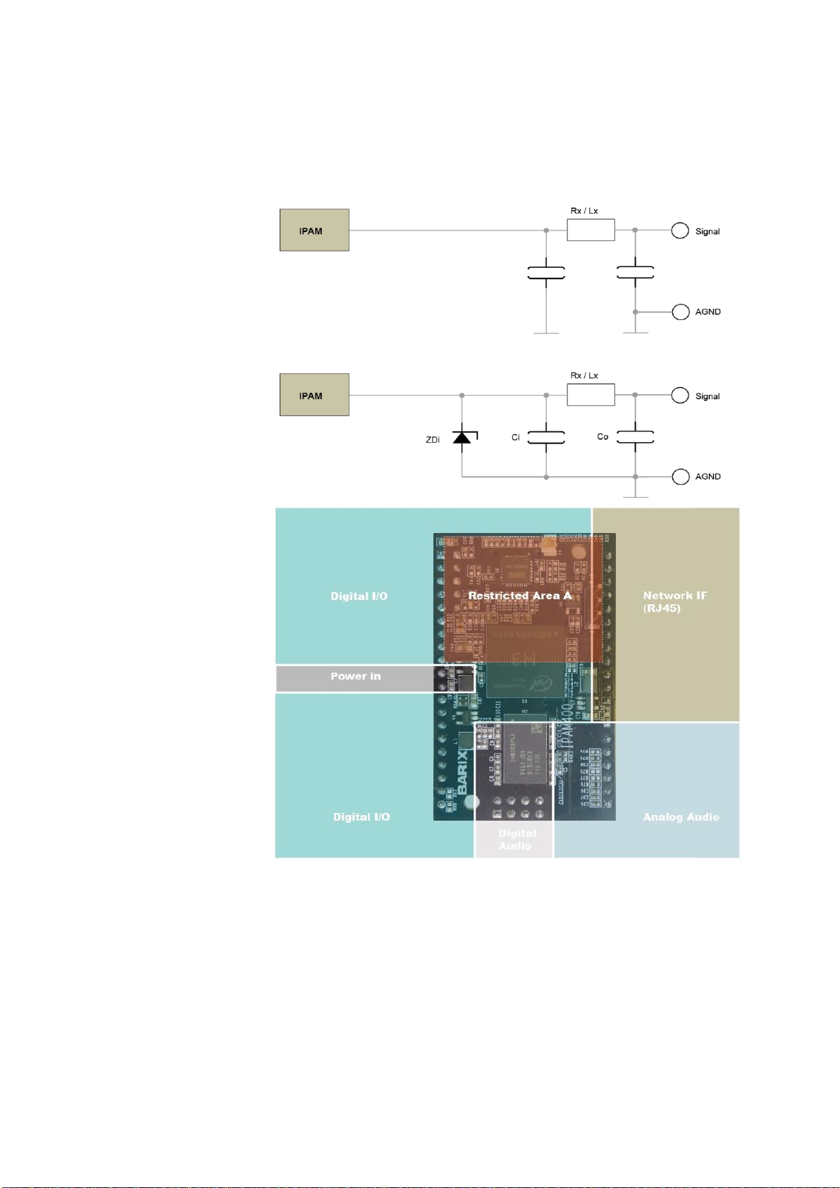
• Avoid signal trace routing crossing domain borders (see graphic on next
page).
• Restricted Area A must not contain any high current switching circuitry nor
any components creating magnetic flux (see graphic on next page).
• Flood unused PCB areas with copper and connect those planes to it's
respective ground.
• Designers should use good PCB layout techniques suited for high speed
bidirectional data bus design when the USB signal run is more than a few
cm in length
• The USB signal lines should be of equal electrical length and track width
for their entire length
• The USB signal lines include provision for termination resistors (to DGND).
The exact value of the terminations may need to be checked or confirmed
by a designer and are in the vicinity of 15 Kilo-Ohms (+/- 5%). These
termination resistors should be close to either the USB socket or the IPAM
connector.
• A more complex (capacitive) termination may be needed under some
circumstances.
• Any unused pins can be left open to save power consumption (no pull-up
or pull-down needed).
• Any unused audio pins can be left open. Only exception is the need of a
1uF capacitor on MICI- (CON3 pin 1) to ground when using as unbalanced
Mic input or when using Line in.
• When planning on variations of carrier PCBs consider a filter consisting of
a resistor/ inductivity and a capacitor (close to the target devices connector)
for audio inputs and outputs:
• For audio inputs always place a filter capacitor (Ci, see schematic
below) to ground just after the above-mentioned resistor/
inductivity (towards the IPAM connector).
For unused audio connectors inputs simply do not populate the
resistor/inductivity. Calculate the values for this R-C filter
according to your use (desired cut-off frequency versus
impedance).
• For audio outputs always place a filter capacitor (Co, see
schematic below) to ground just after the above-mentioned
resistor/ inductivity (towards the IPAM connector) and populate
the resistor/inductivity. Calculate the values for this R-C filter
according to your use (desired cut-off frequency versus
impedance).
Page 12
Preliminary Development – BARIX IP AUDIO MODULE 400 – V 02.20 – 9.April.2018
Layout Guidelines 12
• Although all audio inputs are DC-decoupled consider the use of current
limiting resistors in the audio signal path close to the devices connectors. It
is a good procedure to also limit the max input voltage to 3.3 volts using
zener diodes (ZDi) right after the resistor.
•
Carrier PCB Power
and Signal
Domains
Relevant excerpt from previous chapter “General Rules”:
• All available ground pins of the Barix Audio Module should be attached
to their respective ground domain.
• You MUST provide analog ground to the PCB and that ground must be
connected to the power supply ground externally to the IPAM (on the
carrier PCB)
• Avoid signal trace routing crossing domain borders (see graphic above).
Page 13

Preliminary Development – BARIX IP AUDIO MODULE 400 – V 02.20 – 9.April.2018
Technical Data 13
Technical da ta
Power supply input
Parameter
Min
Max
Unit
Supply voltage (Nominal)
3.3
3,3
VDC
Supply voltage (Absolute Maximum
Ratings)
3.2
3.4
VDC
Power consumption max.
4 W
CPUs / Boot / Memory
Parameter
Details
Central
processor unit
Quad-core ARM CortexTM –A7 MPCoreTM Processor
Boot
Supports fast boot process from Flash or SD/TF card
Encryption
Crypto Engine (CE)
Memory features
• 32KB L1 Instruction cache and 32KB L1 data cache per core
• 512KB L2-cache
• VFPv4 Floating point unit
• Supports LPAE and NEON Advanced SIMD
Memory
16MB SPI flash
Ext. memory
Supports TF and SD card
Network interfaces
Parameter
Details
Ethernet type
10/100 Base (integrated PHY)
Functionality
10/100 Mbit, full / half duplex, auto negotiation
Status display
Link / Activity LED
Protocols
TCP/IP, UDP, RTP, SIP, DHCP
Serial interfaces
Parameter
COM 1 (UART 0)
Signals
RxD, CTS both TTL 3.3 VDC, TxD, RTS both TTL 3.3VDC (VH
min. 0.7*Vin), GND
Baud rates
300 .. 115200
Data bits
7 or 8
Parity
No, Even, Odd
Stop bits
1 or 2
Flow control
No, XON/XOFF
Peripheral I/O
interfaces
Parameter
Min
Max
Unit
IIN/Out current for input and output
-40
40
mA
VIL Input Low Voltage
-0.3
0.3*Vin
VDC
VIH Input High Voltage
0.7*Vin
Vin+0.3Vdc
VDC
VOL Output low voltage @IOL max 4 mA
0
0.2
VDC
VOH Output high voltage @IOH max 4 mA
Vin-0.2Vdc
Vin
VDC
~
Audio interfaces
Audio Processor (Codec)
Decoding features
Format
Sampling rate / Bit rate & type
PCM 16bit linear
8..48 kHz
PCM 8bit logarithmic (µLaw / aLaw)
8..48 kHz
G.722
16 kHz
Ogg Vorbis
1
48 kHz / 500 kbps
MPEG1 & MPEG2 Layer 3 (MP3)
1
8 to 48 kHz / 32..192 kbps, constant bit
rate (CBR) and variable bit rate (VBR)
1
in a future firmware release
Page 14

Preliminary Development – BARIX IP AUDIO MODULE 400 – V 02.20 – 9.April.2018
Technical Data 14
Audio interfaces
Line Input and A/D Conversion
typical values
Parameter
Value
Unit
Input clipping level (input gain set to 0 dBu)*
0.975
2.76
+2
V
RMS
V
PP
dBu
Analog input impedance
2000
Ω
Frequency response (-3dB) @ 48 kHz sample rate
PCM
20..22750
Hz
Signal-to-noise ratio (SNR)
>90dB
dB
Dynamic Range (16 bit theoretical)
96
dB
Total Harmonic Distortion (THD @ -3dBFS)
<0.02
%
Interchannel Isolation (Stereo Cross Talk)
Better -60
dB
*Software selectable input gain from -3db to +19.5dB in 1.5 dB steps
Audio interfaces
Microphone input and A/D
conversion typical values
Parameter
Value
Unit
Input clipping level (at input gain 0 dB and
microphone gain 21dB)*
0.111
-26.9
VPP
dBu
Analog input impedance (differential)
18
kΩ
Frequency response (-3dB) @48 kHz sample rate PCM
21..22'750
Hz
Analog line input signal-to-noise ratio (SNR)
-73
dB
Dynamic Range (16 bit theoretical)
96
dB
Input Total Harmonic Distortion (THD @ -3dBFS)
0.018
%
* Software selectable input gain on microphone input
Audio interfaces
Line output and D/A
conversion typical values
Parameter
Value
Unit
Full Scale Output Voltage (Peak-to-peak) unloaded *
2.39
0.844
0.745
VPP
V
RMS
dBu
Analog output impedance
tbd
Ω
Frequency response (-3dB) @ 48 kHz sample rate PCM
20..21500
Hz
Output signal-to-noise ratio (SNR)
>92
dB
Dynamic Range (16 bit theoretical)
96
dB
Output Total Harmonic Distortion (THD @ -3dBFS)
0.029
%
Interchannel Isolation (Stereo Cross Talk)
Better -66
dB
*Output level (software controllable) set to max.
Mechanical
Dimensions
Weight
14 grams / 0.494 oz. Min. 950 000h acc. to MIL217F at 40°
Parameter
Length
Height
Width
Unit
Complete Printed Circuit Board
56.1
2.2
11.44
0.45
33.0
1.3
mm
inch
Printed Circuit Board only
1.27
0.05
mm
inch
Connector height above PCB
component side
8.9
0.35
mm
inch
Connector height above PCB rear
side
1.27
0.05
mm
inch
Component height max above PCB
5.6
0.22
mm
inch
Page 15
Preliminary Development – BARIX IP AUDIO MODULE 400 – V 02.20 – 9.April.2018
Technical Data 15
MTBF calculations
Parameter
Value
Unit
MTBF calculated according to
MIL217F
-
Calculated Supply Voltage
3.3
VDC
Calculated Temperature (ambient)
25
77
° C
° F
Calculated Temperature (inside device, e.g. Barix
Instreamer)
40
104
° C
° F
Calculation for Ground Mobile Device
TBD
hours
Calculation for Ground Fix Device
950000
hours
Environmental
Parameter
Value
Unit
Operating Temperature Range
-20…+65
-4…149
° C
° F
Operating Humidity Range (non-condensing)
0..70
%
Storage Temperature Range
0...+70
32....158
° C
° F
Storage Humidity Range (non-condensing)
0...70
%
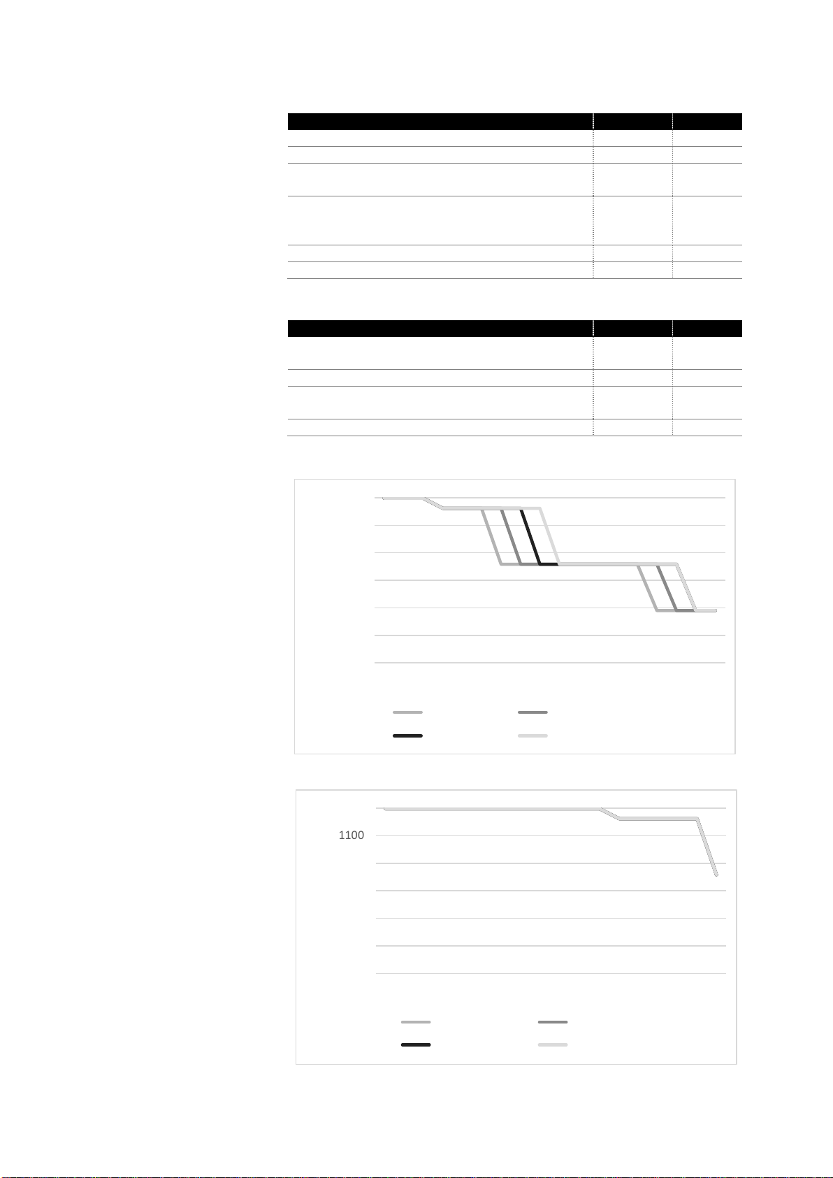
Core frequency versus
Temperature variation
(CPU load: 100%)
Core frequency versus
Temperature variation
(CPU load: 50%)
100
300
500
700
900
1100
1300
-40 -30 -20 -10 0 5 10 15 20 25 30 35 40 45 50 55 60 65
Core 1 freq.(MHz) Core 2 freq.(MHz)
Core 3 freq.(MHz) Core 4 freq.(MHz)
t (° C)
f
(MHz)
100
300
500
700
900
1100
1300
-40 -30 -20 -10 0 5 10 15 20 25 30 35 40 45 50 55 60 65
Core 1 freq.(MHz) Core 2 freq.(MHz)
Core 3 freq.(MHz) Core 4 freq.(MHz)
f
(MHz)
t (° C)
Page 16

Preliminary Development – BARIX IP AUDIO MODULE 400 – V 02.20 – 9.April.2018
Certifications /
Compliances
Complies with RoHS
FCC ID
RED
CE
FCC WARNING
This device complies with part 15 of the FCC Rules. Operation is subject to the following two conditions: (1)
this device may not cause harmful interference, and (2) this device must accept any interference received,
including interference that may cause undesired operation.
Any changes or modifications not expressly approved by the party responsible for compliance c ould void the
user's authority to operate the equipment.
NOTE: This equipment has been tested and found to comply with the limits for a Class B digital device,
pursuant to Part 15 of the FCC Rules. These limits are designed to provide reasonable protection against
harmful interference in a residential installation. This equipment generates, uses and can radiate radio
frequency energy and, if not installed and used in accordance with the instructions, may cause harmful
interference to radio communications. However, there is no guarantee that interference will not occur in a
particular installation.
If this equipment does cause harmful interference to radio or television reception,
which can be determined by turning the equipment off and on, the user is encouraged to try to correct the
interference by one or more of the following measures:
-- Reorient or relocate the receiving antenna.
-- Increase the separation between the equipment and receiver.
-- Connect the equipment into an outlet on a circuit different
from that to which the receiver is connected.
-- Consult the dealer or an experienced radio/TV technician for help.
To maintain compliance with FCC’s RF Exposure guidelines, This equipment should be installed and
operated with minimum distance between 20cm the radiator your body: Use only the supplied antenna.
Changes or modifications made to this equipment not expressly approved by (BARIX) may void the FCC
authorization to operate this equipment
FCC ID: 2APAE-IPAM400
Technical Data 16
Page 17

Preliminary Development – BARIX IP AUDIO MODULE 400 – V 02.20 – 9.April.2018
Ordering Info rmation
IPAM 400 2017.9xxx
© 2017 Barix AG, Dübendorf, Switzerland.
All rights reserved.
All trademarks belong to their respective owners and are used for reference only.
Barix and Barix IP Audio Module are trademarks of Barix AG, Switzerland and are registered in certain
countries.
Newest information about our devices is available via download from our website, www.barix.com.
We explicitly reserve the right to change and improve the product without notice.
Barix AG
Ringstrasse 15a
8600 Dübendorf
SWITZERLAND
T +41 43 433 22 11
F +41 44 274 28 49
www.barix.com
[email protected]
[email protected]
 Loading...