

Page 1

BARIONET
100
Quick Install Guide
Version 2.0
IP Automation Controller with Modbus / TCP and SNMP Support
Package contents
a Barionet 100
b 3wire bus cable
Mounting, Wiring and Setup
Slide the device upwards onto the DIN rail. Push it up and towards the rail
until it snaps onto the upper rail edge. For wiring information please refer
to the second page. Before powering the device please read the user
manual available on www.barix.com.
Firmware
This device comes preloaded with standard firmware.
Alternative firmware can be downloaded from www.barix.com.
Support
For support please contact your local dealer or visit www.barix.com.
© Barix AG 3/2013, all r ights reser ved. All informati on is subjec t to change with out notice. A ll mentione d trademar ks belong
to their res pective own ers and are us ed for referen ce only. Barix, E xstreamer and So nicIP are trad emarks of Ba rix AG, Switze rland,
and are reg istered in ce rtain cou ntries.
Page 2
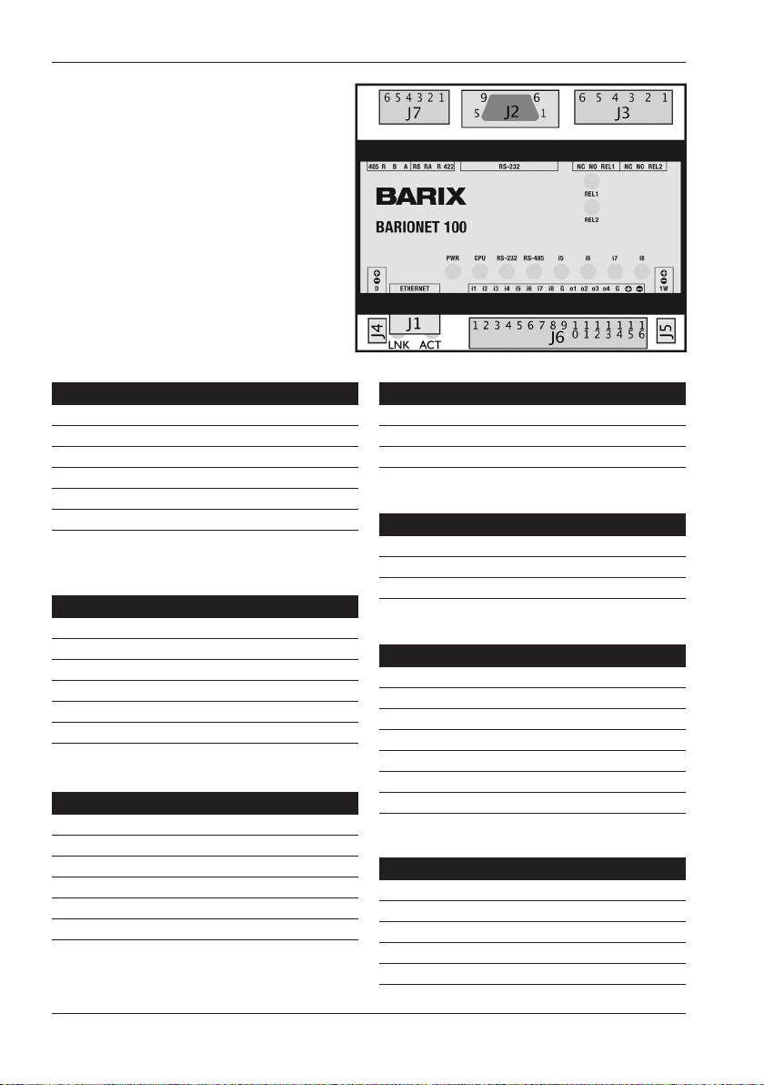
Top vi ew
J1 LAN por t 10/100 (RJ45)
Pin Description
1 TX+ (Transm it data)
2 TX- (Trans mit data)
3 TxD (Receiv e data)
6 GND (Rec eive data)
7 RTS (Read y to send)
8 CTS (Clea r to send)
Left LED L ink, righ t LED Activit y (speed/co lor code se e manual)
J2 RS-23 2 serial port
Pin Description
2 RxD (Re ceive data)
3 TxD (Transmit d ata)
5 GND (Grou nd)
7 RTS (Read y to send)
8 CTS (Clea r to send)
1,4,6,9 not connected
J3 Rel ay outp uts (25 0VAC, 5A)
Pin Description
1 Relay 2 common
2 Relay 2 no rmally op en
3 Relay 2 no rmally cl osed
4 Relay 1 common
5 Relay 1 no rmally op en
6 Relay 1 no rmally cl osed
J4 Power bus
Pin Description
1 Power +9..30 VDC (o ut 1A max.)
2 Ground (G ND)
3 Defaul ts (for factor y defaults r everting s ee manual !)
J5 Dallas 1-wire® bus
Pin Description
1 Power +9..30 VDC (o ut 1A max.)
2 Ground (G ND)
3 1-wire data
J6 I/O and Power (4Watt max.)
Pin Description
1..4 Input 1..4 Analog 0..5 VDC or D igital (cl ose to Ground )
5..8 Input 5..8 Digita l (close to Grou nd)
9 Ground fo r Inputs
10 Output 1 D igital (Op en Colle ctor 0..24 VDC, 100 mA)
14 Ground fo r Outputs
15 Power In + 9..30VD C
16 Power In -
J7 RS- 422/485 p ort (det. screw term. block)
Pin 422 485
1,6 Shield Shield
2 RXA Not used
3 RXB Not used
4 TXA A
5 TXB B
Page 3

3 Setting temporary IP address
using ARP command
This pro cedure will work onl y in a local n etwork.
After th is proced ure the temp orary IP w ill be acti ve
only until restar t/rebo ot. After a res tart the p rocedur e
has to be repeated.
STEP 1
Either use a network cable to link the Barionet and
the PC directly, or connect the Barionet to the PC
via your n etwork sw itch and powe r the devic e. Make
sure that you have a valid s tatic IP add ress conf igured on
your PC (e.g. 192.168.0.2)
STEP 2
Window s : For a comma nd window. cli ck on «Star t», click
on «Run..», in the «O pen» fie ld type cm d , click on «O K».
OSX / Linu x : Open a term inal wind ow.
STEP 3
Please proceed to step 4 if you linke d the PC dire ctly to
the devi ce in step 1. To ensure that you use a free I P
addres s (not already used by another devi ce in the net work)
please use the Ping command. To verify availability in
this example we assu me the PC to have th e IP addres s
«192.168.0.2» and want to che ck if «192.168.0.6» is free.
Typ e p in g 1 92.168.0.6 and hit th e «Enter» key. You
should get no reply w hich give s you reaso nable ass ertion
that the «p inged» IP is availabl e.
STEP 5
Now we have to ma ke the Barionet listen to the IP
addres s «192.168.0.6» using the Telnet command. To do so
type into the comma nd window telnet 192.168.0.6 1
and hit th e «Enter» key (the n umber «on e» must be there for
this command to work correctly !!!). The Barionet will imme-
diately refuse the connection on port 1, but will be available
for brows er access as long as the d evice stays powered.
STEP 6
To check if the B ari one t is respo nding you can use
the ping c ommand ag ain. To do so type p in g 1 92.168.0.6
and hit th e «Enter» key. If you do ge t a reply the IP a ddress
192.168.0.6 can be us ed to acces s the Bario net using a we b
browser. Please go back to s ection «2 Net work configuratio n
by web brows er» to configur e a static IP address. If you d o get
«reque st timed ou t» then pleas e repeat ste p 5 careful ly (you
most like ly misty ped the telnet comma nd) or repe at the entire
procedure. If the AR P method does not work for y ou, refer to
the user manual for further methods.
4 Troubleshooting
• If the p ower statu s LED (PWR) stays da rk chec k the powe r
cabling (installation step 2).
• Check if the LI NK LED (on J1) is li t, if it is not then
check your network cabling.
• If you h ave doubts about th e curren t device setting s
you can revert the de vice to its factory defa ults by
following the procedure explained in the manual.
STEP 4
Look for th e Barion et’s MAC addres s printed on a
label o n the bottom of t he device (12 hex dig its, separ ated
by a hyphe n every 2 digits). Type into the windows com-
mand window
arp -s 192.168.0.6 00-08-E1-00-B1-77
or on a OSX or L inux syste m type into th e terminal
arp -s 1 92.168.0.6 00:08:E1:00:B1:77
and hit th e «Enter» key (replace the dig its accord ing to your
devices MAC address). You must have administrative rights
to be able to d o so (sudo on OSX / L inux).
Barix AG, Seefeldstrasse 303, CH-8008 Zürich
P +41 43 433 22 11
[email protected], www.barix.com
For information about our products, manuals, technical
documentation, latest firmware, support and access to
the user forum please visit www.barix.com.
Page 4
1 Installation
STEP 1
Plug a standard (straight) network cable (not included)
into the network por t (J1) of the Barione t and the othe r end
into your hub or switch.
You can also use a crossove r network c able (not in cluded)
for a direct connection to your PC.
STEP 2
To power the dev ice wire the p ositive terminal of yo ur power
suppl y (9..30 VDC, not inc luded) to pi n 15 (Power In +) and
the negative termi nal to pin 16 (Power In -) of c onnector J6.
STEP 3
Connect your power supply to an electrical outlet.
STEP 4
The LNK L ED will light up green si gnallin g establi shed
link.The ACT LED w ill blink w hile Bari onet acqu ires an IP
addres s, (if no DHC P server i s availabl e this can ta ke up to
5 min utes).
See the next page for t he ARP comm and proce dure, or
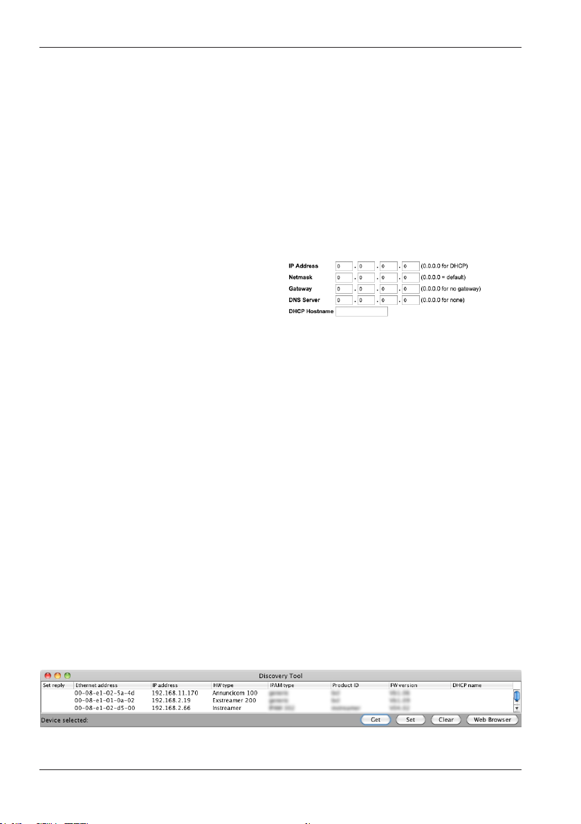
use the “B arix Dis covery Tool” J ava applic ation (download
the latest version from www.barix.com) on your computer
(Win dows, Mac or L inux) and c lick the “Ge t” button to f ind
out whi ch IP addres s the devic e has obtai ned (see pic ture
at the bot tom of the page). Ma ke sure that th e Ethernet
addres s (MAC) matches your devi ce (see label on the
bottom of the device).
Now that yo u know the IP ad dress proceed to the nex t
section “Network configuration by web browser”.
If you were n ot able to obta in the device’s current
IP addre ss with the previous ste ps see sec tion
"Troubleshooting".
2 Network configuration
by web browser
Most Barix applictaions require no configuration but use
DHCP to configure network settings dynamically.
If you nee d to use static (fixed) net work set tings foll ow
steps 1 to 3, oth erwise c ontinue f rom step 4.
STEP 1
Open your web browse r.
STEP 2
Enter the I P address of t he Barion et and pres s Enter
(Example: 192.168.0.12). Click on the Configuration button,
then go to Ad vanced Se ttings/ Network.
STEP 3
In order to m ake the appl ication wo rk (e.g. "Digital I/O and
Serial Tunnel") the following parameters must be set (check
with your network administrator):
• static IP addres s (the default «0.0.0.0 » sets au tomatic
discovery: BootP, DHCP) and netmask
If you your d evices are connec ted via route rs also:
• Gateway I P addres s
Hit the «A pply» but ton to save all ch anges. Th e device will
reboot w ith the conf igured IP a ddress.
STEP 4
To complete the application setup, download the firmware
documentation from www.barix.com. Download the
product manual for additional information about the hard-
ware installation, technical and mechanical details
as well as i nstructi ons on updating or cha nging the loaded
application and firmware.
 Loading...