

Bard WERVPA5, WERVPC5 Installation Instructions Manual

INSTALLATION INSTRUCTIONS
WALL MOUNT ENERGY RECOVERY
VENTILATOR WITH EXHAUST
AND OUTDOOR AIR SHUT-OFF DAMPER
Models:
WERVPA5 WERVPC5
For Use With Bard 3.5 – 6 Ton
Wall Mount Air Conditioners and Heat Pumps
Bard Manufacturing Company, Inc.
Bryan, Ohio 43506
www.bardhvac.com
Manual: 2100-635A
Supersedes: 2100-635
Date: 3-21-18
Page 1 of 18

CONTENTS
Model Nomenclature .............................................. 3
Electrical Specifications ......................................... 3
General Description .............................................. 3
General Information .............................................. 3
Unpacking ............................................................ 3
Performance and Application Data – WERVP*5 ........ 4
Basic Field Installation ........................................... 5
Basic Installation (Factory-Installed Versions) ......... 12
Control Wiring ..................................................... 12
Ventilation Airflow ................................................ 13
Energy Recovery Ventilator Maintenance ................ 16
Figures
Figure 1 Remove Blower Assembly and
Discard Shipping Plate ........................ 5
Figure 2 Remove Access Panels ........................ 6
Figure 3 Remove Air Filter and
Exhaust Cover Plate ............................ 7
Figure 4 Install Exhaust Blower Assembly ........... 8
Figure 5
Figure 6 Connect Leads to Terminals ............... 10
Figure 7
Figure 8 Speed Tap Label ............................... 13
Figure 9 Airflow Diagram ................................ 13
Figure 10 Heat Pump Wiring ............................. 14
Figure 11 Heat Pump Wiring w/CO
and CompleteStat ............................. 15
Figure 12 Belt Replacement Instructions ........... 17
Figure 13 Hub Assembly with Ball Bearings ....... 18
Table
Table 1 Ventilation Air ................................... 12
Plug Exhaust Blower Into Control Panel
Attach Hood and Replace Access Panel
Controller
2
.. 9
. 11
Manual 2100-635A
Page 2 of 18
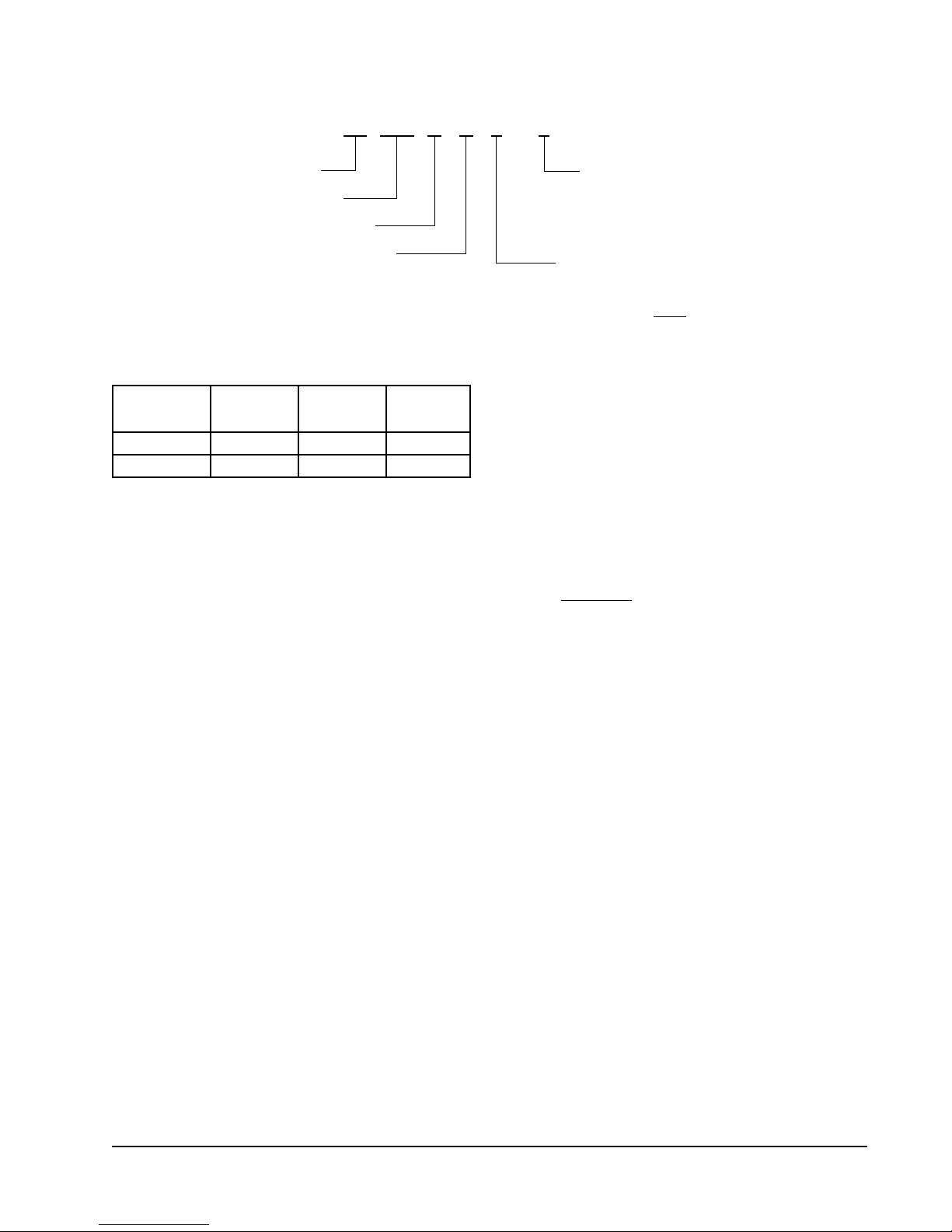
WALL MOUNT ENERGY RECOVERY VENTILATOR MODEL NOMENCLATURE
W ERV P A 5 – X
W – Wall Mount Color
Energy Recovery Ventilator
Plug-In Vent Connection
Electrical
A – 230/208 volt
C – 460 volt
X – Beige
1 – White
4 – Gray
5 – Desert Brown
Wall Mount – Cabinet Size
5 – W42A* thru W72A*
W42H* thru W60H*
(* revision letter)
8 – Dark Bronze
A – Aluminum
S – Stainless
ELECTRICAL SPECIFICATIONS
Model Voltage Amps
WERVPA5 230/208 2.2 24V
WERVPC5 460 1.2 24V
Control
Voltage
GENERAL DESCRIPTION
The Wall Mount Energy Recovery Ventilator was
designed to provide energy efficient, cost effective
ventilation to meet IAQ (Indoor Air Quality)
requirements while still maintaining good indoor
comfort and humidity control for a variety of
applications such as schools, classrooms, lounges,
conference rooms, beauty salons and others. It
provides a constant supply of fresh air for control
of airborne pollutants including CO
formaldehyde, excess moisture, virus and bacteria.
The ventilator incorporates patented rotary heat
exchanger technology to remove both heat and moisture.
It is designed as a single package which can be easily
factory or field installed for new installations or retrofit
to the new Bard W series wall-mounted units. The
package consists of a unique rotary Energy Recovery
Cassette that can be easily removed for cleaning or
maintenance. The WERVP*5 has two 15" diameter
heat transfer wheels for efficient heat transfer. The
heat transfer wheels use a permanently bonded dry
desiccant coating for total heat recovery. An outdoor
air shutoff damper is an integral feature of the WERVP
and prevents infiltration when the ERV is turned off.
, smoke, radon,
2
effectively during both summer and winter conditions.
Provides required ventilation to meet the requirements
of ASHRAE 62.1 standard.
NOTE: During operation below 5°F outdoor
temperature, freezing of moisture in the heat
transfer wheel can occur. Consult the factory if
this possibility exists.
GENERAL INFORMATION
NOTE: This manual covers both factory- and field-
installed WERVP assemblies. For factoryinstalled WERVP, skip information pertaining to
installation of the WERVP system.
The ventilator should only be installed by a trained
heating and air conditioning technician. These
instructions serve as a guide to the technician installing
the ventilator package. They are not intended as a stepby-step procedure with which the mechanically inclined
owner can install the package. The ventilator housing is
shipped in one carton which contains the following:
• Energy recovery ventilator
• Service door
• Rain hood and mist eliminator
• Installation instructions
UNPACKING
Upon receipt of the equipment, be sure to compare the
model number found on the shipping label with the
accessory identification information on the ordering and
shipping document to verify that the correct accessory
has been shipped.
Ventilation is accomplished with two blower/motor
assemblies each consisting of a drive motor and dual
blowers for maximum ventilation at low sound levels.
The intake and exhaust blowers can be operated at the
same speed (airflow rate) or different speeds to allow
flexibility in maintaining desired building pressurization
conditions. Factory shipped on medium intake and low
exhaust. See Figure 8 on page 13 to change speeds.
The rotating energy wheels provide the heat transfer
Inspect the carton housing of each ventilator as it is
received and before signing the freight bill, verify that
all items have been received and that there is no visible
damage. Note any shortages or damage on all copies
of the freight bill. The receiving party must contact
the last carrier immediately, preferably in writing,
requesting inspection by the carrier’s agent. Concealed
damage not discovered until after loading must be
reported to the carrier within 15 days of its receipt.
Manual 2100-635A
Page 3 of 18
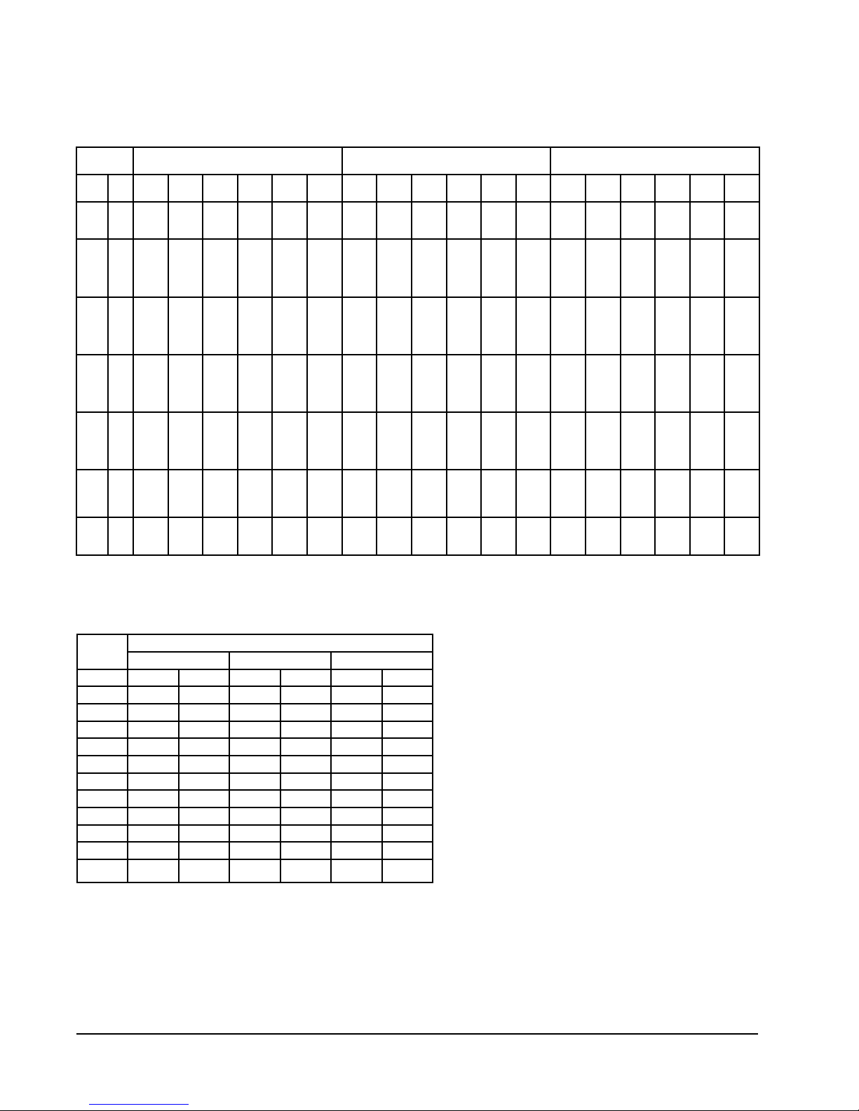
PERFORMANCE AND APPLICATION DATA – WERVP*5
Summer Cooling Performance
(Indoor Design Conditions 75°DB/62°WB)
Ambient
OD
DB/
F VLT VLS VLL HRT HRS HRL V LT VLS VLL HRT HRS HRL V LT VLS VLL HRT HRS HRL
WB
1057570
100
95
90
85
80
757065
21465
14580
65
14580
80
31590
75
21465
70
12352
65
12150
60
12150
80
31590
75
21465
70
12352
65
9720
60
9720
80
31590
75
21465
70
12352
65
7290
60
7290
80
31590
75
21465
70
12352
65
4860
60
4860
75
21465
70
12352
65
4252
60
2430
12352
4252
60
Ventilation Rate 450 CFM Ventilation Rate 375 CFM Ventilation Rate 300 CFM
3786
14310
4475
17887
12150
5737
11805
14580
6884
13952
14580
14580
12150
12150
12150
12150
12150
9720
9720
9720
9720
9720
7290
7290
7290
7290
7290
4860
4860
4860
4860
4860
2430
2430
2430
2430
0
0
0
19440
9314
202
0
0
21870
11744
2632
0
0
24300
14175
5062
0
0
26730
16605
7492
0
0
19035
9922
1822
0
0
12352
0
4252
0
0
9477
9477
20533
13952
8029
7897
7897
20553
13952
8029
6318
6318
20533
13952
8029
4738
4738
20533
13952
8029
3159
3159
13952
8029
2764
1579
8029
2764
0
9477
9477
9477
7897
7897
7897
7897
7897
6318
6318
6318
6318
6318
4738
4738
4738
4738
4738
3159
3159
3159
3159
3159
1579
1579
1579
1579
0
12150
12150
26325
17887
10293
10125
10125
26325
17887
10293
8100
8100
26325
17887
10293
6075
6075
26325
17887
10293
4050
4050
17887
10293
3543
2025
10293
3543
0
12150
12150
10125
10125
10125
10125
10125
0
12635
6054
131
0
0
14215
7634
1711
0
0
15794
9213
3290
0
0
17374
10793
4870
0
0
12372
6449
1184
0
8029
0
2764
0
0
0
8100
8100
8100
8100
8100
6075
6075
6075
6075
6075
4050
4050
4050
4050
4050
2025
2025
2025
2025
0
0
0
0
0
16200
7762
168
0
0
18225
9787
2193
0
0
20250
11812
4218
0
0
22275
13837
6243
0
0
15862
8268
1518
0
10293
3543
0
8018
8018
17374
11805
6793
6682
6682
17374
11805
6793
5345
5345
17374
11805
6793
4009
4009
17374
11805
6793
2672
2672
11805
6793
2338
1336
6793
2338
0
8018
8018
8018
6682
6682
6682
6682
6682
5345
5345
5345
5345
5345
4009
4009
4009
4009
4009
2672
2672
2672
2672
2672
1336
1336
1336
1336
0
0
0
0
0
10692
5123
111
0
0
12028
6459
1447
0
0
13365
7796
2784
0
0
14701
9132
4120
0
0
10469
5457
1002
0
6793
2338
0
9720
9720
21060
14310
8235
8100
8100
21060
14310
8235
6480
6480
21060
14310
8235
4860
4860
21060
14310
8235
3240
3240
14310
8235
2835
1620
8235
2835
0
9720
9720
9720
8100
8100
8100
8100
8100
6480
6480
6480
6480
6480
4860
4860
4860
4860
4860
3240
3240
3240
3240
3240
1620
1620
1620
1620
0
0
0
4590
0
0
12960
6210
135
0
0
14580
7830
1755
0
0
16200
9450
3375
0
0
17820
11070
4995
0
0
12690
6615
1215
0
8235
2835
0
9587
6512
6512
14110
9587
5517
5427
5427
14110
9587
5517
4341
4341
14110
9587
5517
3256
3256
14110
9587
5517
2170
2170
9587
5517
1899
1085
5517
1899
0
6512
6512
6512
5427
5427
5427
5427
5427
4341
4341
4341
4341
4341
3256
3256
3256
3256
3256
2170
2170
2170
2170
2170
1085
1085
1085
1085
0
0
0
3075
0
0
8683
4160
90
0
0
9768
5246
1175
0
0
10854
6331
2261
0
0
11939
7416
3346
0
0
8502
4432
814
0
5517
1899
0
Winter Heating Performance
(Indoor Design Conditions 70°F DB)
Ambient
OD
DB/°F WVL WHR WVL WHR WVL WHR
65 2430 1944 2025 1640 1620 1328
60 4860 3888 4050 3280 3240 2656
55 7290 5832 6075 4920 4860 3985
50 9720 7776 8100 6561 6480 5313
45 12150 9720 10125 8201 8100 6642
40 14580 11664 12150 9841 9720 7970
35 17010 13608 14175 11481 11340 9298
30 19440 15552 16200 13122 12960 10627
25 21870 17496 18225 14762 14580 11955
20 24300 19440 20250 16402 16200 13284
15 26730 21384 22275 18042 17820 14612
450 CFM 375 CFM 300 CFM
NOTE: Sensible performance only is shown for winter
application.
Ventilation Rate
LEGEND:
VLT = Ventilation Load – Total
VLS = Ventilation Load – Sensible
VLL = Ventilation Load – Latent
HRT = Heat Recovery – Total
HRS = Heat Recovery – Sensible
HRL = Heat Recovery – Latent
WVL = Winter Ventilation Load
WHR = Winter Heat Recovery
NOTE: All performance data is based on
operating intake and exhaust blower on
the same speed.
Manual 2100-635A
Page 4 of 18
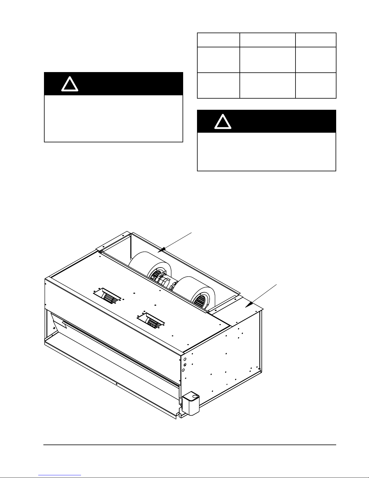
BASIC FIELD INSTALLATION
MIS-2233
Discard Shipping
plate
Remove Exhaust
Blower Assembly
1. Unpack the ventilator assembly which includes the
integral ventilator with attached electrical harness
and miscellaneous hardware.
!
WARNING
Open and lock unit disconnect switch
before installing this accessory to prevent
injury or death due to electrical shock or
contact with moving parts. Turn thermostat
to OFF.
2.
Remove exhaust blower assembly from back of
ventilator and discard shipping plate (see Figure 1).
FIGURE 1
Remove Blower Assembly and Discard Shipping Plate
Model
WERVPA5
WERVPC5
!
Be sure the correct model and voltage
energy recovery ventilator is used with
the correct air conditioner or heat pump to
ensure correct voltage compatibility.
For Use With the
Following Units
W42AA/W42HA-A, -B
W48AA/W48HA-A, -B
W60AA/W60HA-A, -B
W72AB-A, -B
W42AA/W42HA-C
W48AA/W48HA-C
W60AA/W60HA-C
W72AB-C
Electrical
230/208 -
1 or 3 phase
460 - 3 phase
CAUTION
REMOVE EXHAUST
BLOWER ASSEMBLY
DISCARD SHIPPING
PLATE
Manual 2100-635A
Page 5 of 18
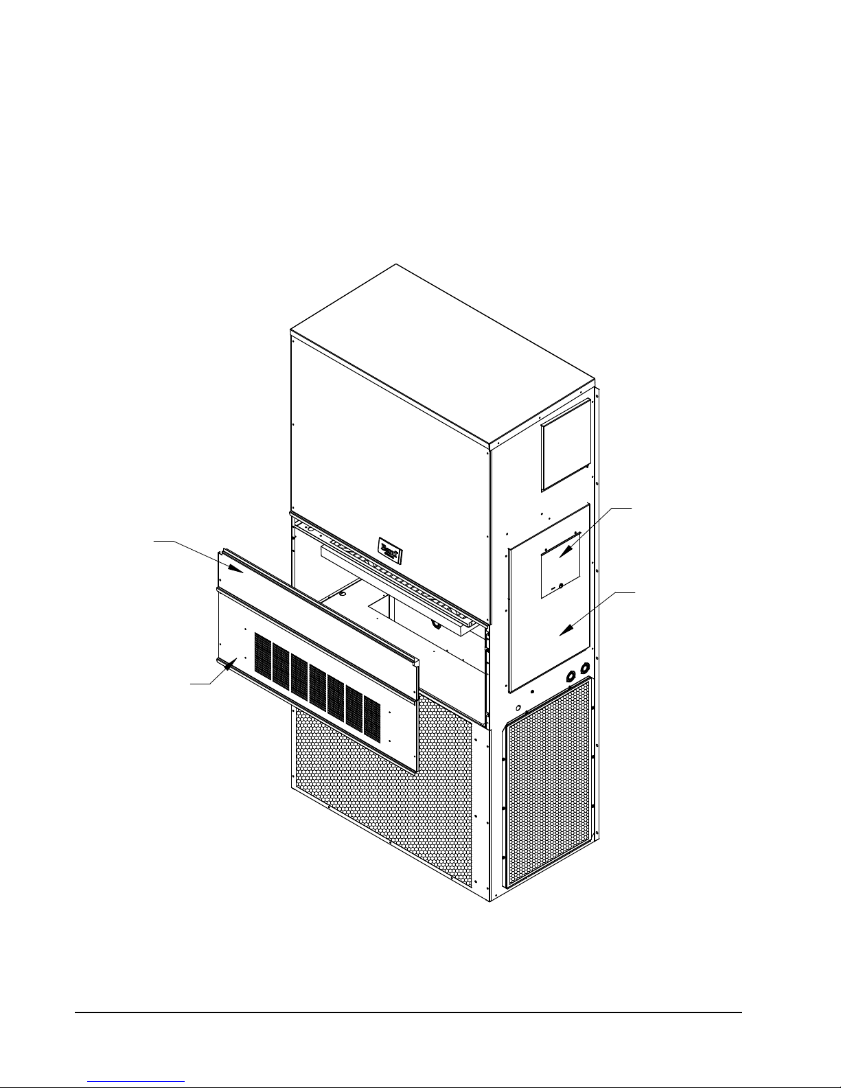
3. Disconnect unit power.
4. Remove the existing exterior filter access and
service access panels on the Bard wall mount unit
(see Figure 2). Save the filter access panel and
discard service access panel.
Remove Access Panels
FIGURE 2
REMOVE & SAVE
FILTER DOOR
REMOVE & DISCARD
SERVICE ACCESS DOOR
CIRCUIT BREAKER
DOOR
CONTROL PANEL
DOOR
Manual 2100-635A
Page 6 of 18
MIS-3744
 Loading...