

Bard WE252, WE301, WE371, WE421, WE482 Installation Instructions Manual
...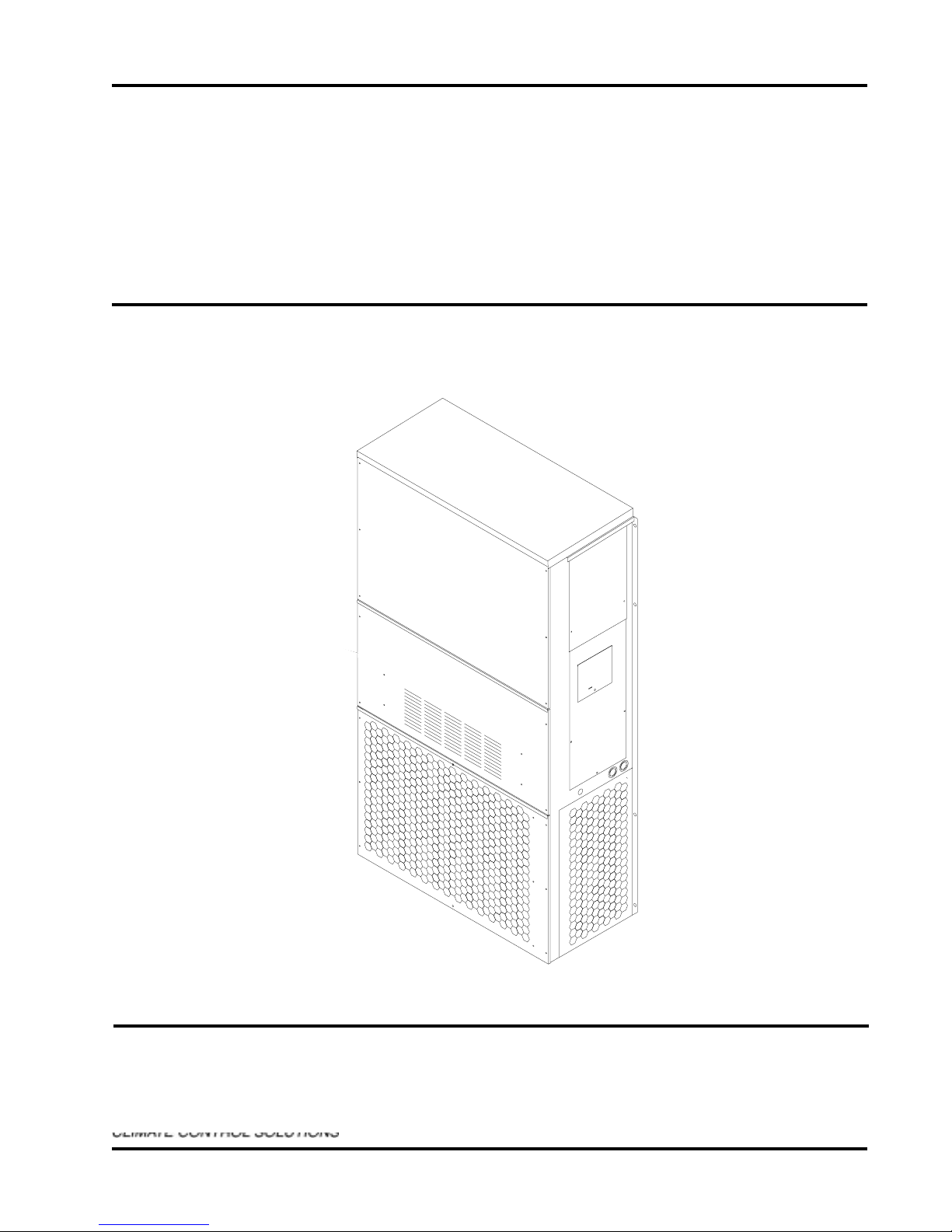
WALL MOUNTED PACKAGED
AIR CONDITIONER
INSTALLATION
INSTRUCTIONS
Models:
WE252 WE301
WE371 WE421
WE482 WE602
WE701
THESE MODELS ALL USE REFRIGERANT R-407C
and ARE FOR 50HZ OPERATION.
Bard Manufacturing Company
Bryan, Ohio 43506
Since 1914...Moving ahead, just as
planned.
MIS-383
Manual No.: 2100-385B
Supersedes: 2100-385A
File: Volume III, Tab 16
Date: 04-25-05
©
Copyright 2002

CONTENTS
Getting Other Information
...................................1
Wall Mount General Information
Model Nomenclature ............................................ 2
Shipping Damage ................................................ 5
General ................................................................ 5
Duct Work ............................................................ 5
Filters ................................................................... 6
Fresh Air Intake .................................................... 6
Condensate Drain ................................................ 6
Installation Instructions
Wall Mounting Information ................................... 7
Proper Unit Placement ......................................... 7
Mounting the Unit ................................................. 7
Wiring – Main Power .......................................... 12
Wiring – Low Voltage ......................................... 12
Start Up
Important Installer Note...................................... 14
High Pressure Switch ........................................ 14
Service Hints ...................................................... 14
Sequence of Operations .................................... 14
Compressor Control Module .............................. 14
Adjustments ....................................................... 15
Phase Monitor .................................................... 15
Pressure Service Ports ...................................... 15
Troubleshooting
Fan Blade Setting Dimensions .......................... 16
Removal of Fan Shroud ..................................... 16
Refrigerant Charge ............................................ 16
Cooling Pressures ............................................. 18
Optional Accessories ......................................... 19
R-407C Refrigerant
Service Procedures & Considerations ............... 20
Charging ............................................................ 20
Leaks ................................................................. 20
Figures
Figure 1 Unit Dimensions................................... 4
Figure 2 Fresh Air Damper Assembly ................ 6
Figure 3 Mounting Instructions........................... 8
Figure 4 Electric Heat Clearance ....................... 9
Figure 5 Wall-Mounting Instructions ................. 10
Figure 6 Wall-Mounting Instructions ................. 10
Figure 7 Common Wall-Mounting Instructions . 11
Figure 8 Low Voltage Wiring Diagram ............. 13
Figure 9 Fan Blade Setting .............................. 16
Tables
Table 1 Electric Heat Table ............................... 2
Table 2 Electrical Specifications ....................... 3
Table 3 Thermostat Wire Size ........................ 12
Table 4 Wall Thermostat and
Subbase Combinations...................... 12
Table 5 Fan Blade Setting Dimension ............ 16
Table 6 Suction Line Temperatures ................ 16
Table 7 Rated CFM and ESP ......................... 16
Table 8 Indoor Blower Performance ............... 17
Table 9 Maximum ESP of Operation –
Electric Heat Only .............................. 17
Table 10 Cooling Pressures ............................. 18
Table 11 Optional Accessories ......................... 19
Table 12 R-407C Temperature/Pressure Chart 20

GETTING OTHER INFORMATION AND PUBLICATIONS
These publications can help you install the air
conditioner or heat pump. You can usually find these at
your local library or purchase them directly from the
publisher. Be sure to consult current edition of each
standard.
National Electrical Code ........................ ANSI/NFPA 70
Standard for the Installation ................ ANSI/NFPA 90A
of Air Conditioning and
Ventilating Systems
Standard for Warm Air ........................ ANSI/NFPA 90B
Heating and Air
Conditioning Systems
Load Calculation for ............................. ACCA Manual J
Residential Winter and
Summer Air Conditioning
Duct Design for Residential ................ ACCA Manual D
Winter and Summer Air
Conditioning and Equipment
Selection
FOR MORE INFORMATION, CONTACT
THESE PUBLISHERS:
ACCA Air Conditioning Contractors of America
1712 New Hampshire Avenue NW
Washington, DC 20009
Telephone: (202) 483-9370
Fax: (202) 234-4721
ANSI American National Standards Institute
11 West Street, 13th Floor
New York, NY 10036
Telephone: (212) 642-4900
Fax: (212) 302-1286
ASHRAE American Society of Heating Refrigerating,
and Air Conditioning Engineers, Inc.
1791 Tullie Circle, N.E.
Atlanta, GA 30329-2305
Telephone: (404) 636-8400
Fax: (404) 321-5478
NFPA National Fire Protection Association
Batterymarch Park
P.O. Box 9101
Quincy, MA 02269-9901
Telephone: (800) 344-3555
Fax: (617) 984-7057
Manufactured under the following U.S. patent numbers:
5,485,878; 5,301,744; 5,002,116;
4,924,934; 4,875,520; 4,825,936
Manual 2100-385B
Page 1
WALL MOUNT GENERAL INFORMATION
AIR CONDITIONER WALL MOUNT MODEL NOMENCLATURE
WE 42 1 — F 07 X X X X X J
MODEL NUMBER
CAPACITY
25 - 2 TON
30 - 2-1/2 TON
37 - 3 TON
42 - 3-1/2 TON
48 - 4 TON
60 - 5 TON
70 - 6 TON
REVISIONS
VOLTS & PHASE
D - 240/220-50-1
F - 415/380-50-3
VENTILATION OPTIONS
X - BAROMETRIC FRESH AIR DAMPER
B - BLANK-OFF PLATE
M - MOTORIZED FRESH AIR DAMPER
V - COMMERCIAL VENTILATOR
MOTORIZED WITH EXHAUST
E - ECONOMIZER (INTERNAL) - FULLY
MODULATING WITH EXHAUST
R - ENERGY RECOVERY VENTILATOR -
MOTORIZED WITH EXHAUST
KW
COLOR OPTIONS
X-
BEIGE (STANDARD)
1 - WHITE
2 - MESA TAN
4 - BUCKEYE GRAY
5 - DESERT BROWN
FILTER OPTIONS
X - ONE INCH THROWAWAY
W - ONE INCH WASHABLE
P - TWO INCH PLEATED
OUTLET OPTIONS
X - FRONT (STANDARD)
COIL OPTIONS
X - STANDARD
1 - PHENOLIC COATED EVAPORATOR
2 - PHENOLIC COATED CONDENSER
3 - PHENOLIC COATED EVAPORATOR
AND CONDENSER
CONTROL
MODULES
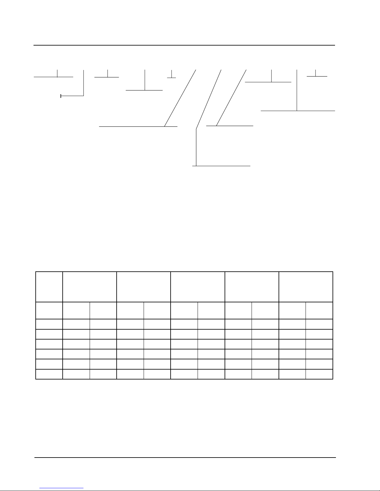
TABLE 1
ELECTRIC HEAT TABLE
D-103EW
sledoMD-252EWF-252EW
WK
1-V042
STTAW
1-V022
STTAW
3-V514
STTAW
3-V083
STTAW
D-173EW
1-V042
STTAW
1-V022
STTAW
0.5110502244844157311050224
0.7 0476656504760665
0.811081276
0.0149991148
0.21 871118049
0.41 0543108211
F-103EW
F-173EW
3-V514
STTAW
3-V083
STTAW
3-V514
STTAW
F-124EW
F-284EW
F-206EW
F-107EW
3-V083
STTAW
Manual 2100-385B
Page 2

TABLE 2
ELECTRICAL SPECIFICATIONS
1
3
gnitarepO
stloVdetaR
ledoM
Z0D-252EW
50D
80D
Z0F-252EW
50F
Z0D-103EW
50D
01D
Z0F-103EW
70F
21F
Z0D-173EW
50D
01D
Z0F-173EW
70F
21F
Z0F-124EW
70F
41F
Z0F-284EW
70F
41F
Z0F-206EW
70F
41F
Z0F-107EW
70F
41F
1
Maximum size of the time delay fuse or HACR type circuit breaker for protection of field wiring conductors.
2
Based on 75°C copper wire. All wiring must conform to NEC and all local codes.
3
These “Minimum Circuit Ampacity” values are to be used for sizing the field power conductors. Refer to the
National Electric Code (latest revision), Article 310 for power conductor sizing.
Caution: When more than one field power conductor circuit is run through one conduit, the conductors must be
derated. Pay special attention to Note 8 of Table 310 regarding Ampacity Adjustment Factors when more than
three (3) conductors are in a raceway.
IMPORTANT: While this electrical data is presented as a guide, it is important to electrically connect properly sized
fuses and conductor wires in accordance with all existing local codes.
esahPdna
1-022/042452-891
3-083/514654-243
1-022/042452-891
3-083/514654-243
1-022/042452-891
3-083/514654-243
3-083/514654-243
3-083/514654-243
3-083/514654-243
3-083/514654-243
egatloV
egnaR
rebmuN
rewoPdleiF
stiucriC
1
1
1
1
1
1
1
1
1
1
1
1
1
1
1
1
1
1
1
1
1
1
1
1
1
1
1
1
1
muminiM
tiucriC
yticapmA
51
72
34
7
01
22
92
55
9
51
32
42
92
55
11
61
52
11
61
03
31
61
03
51
61
03
91
91
23
mumixaM
lanretxE
esuF
tiucriCro
rekaerB
02
03
54
51
51
53
53
06
51
51
52
53
53
06
51
02
52
51
02
03
02
02
03
02
02
03
52
52
53
2
rewoPdleiF
eziSeriW
21
01
8
41
41
8
8
6
41
41
01
8
8
6
41
21
01
41
21
01
21
21
01
21
21
01
01
01
01
2
dnuorG
eziSeriW
21
01
01
41
41
01
01
01
41
41
01
01
01
01
41
21
01
41
21
01
21
21
01
21
21
01
01
01
01
Manual 2100-385B
Page 3
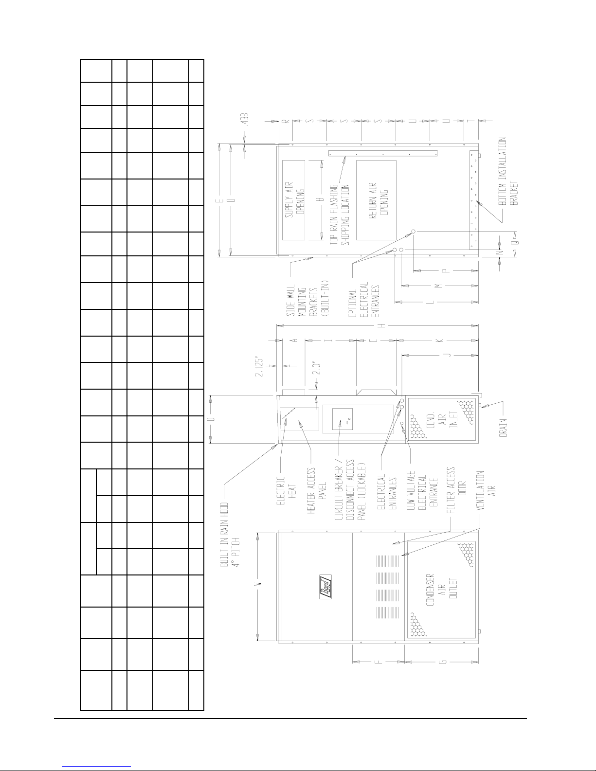
MIS-1665
BACK VIEW
FIGURE 1
UNIT DIMENSIONS (IN INCHES)
EFGI JKLMNOPQRSTUABCB
ylppuSnruteR
thgieH
)H(
htpeD
)D(
htdiW
)W(
ledoM
2.83572.71365.0788.788.7288.3188.720.045.8157.5239.7157.6257.8252.920.7257.291.9357.2241.991.40.210.50.21
103EW
252EW3.33521.71365.0788.788.9188.1188.910.535.8157.5265.0257.6260.8252.920.7236.231.4360.2255.0191.40.210.50.21
173EW
124EW
570.24234.22578.4888.988.9288.5188.9288.3401.9166.130.0386.2349.6296.4334.2373.388.2488.320.0144.10.6188.10.61
284EW
206EW
SIDE VIEW
FRONT VIEW
107EW570.2434.22578.4988.988.9288.5188.9288.3401.9166.140.0386.240.7357.445.2473.388.2488.330.010.20.6188.10.12
Manual 2100-385B
Page 4

SHIPPING DAMAGE
DUCT WORK
Upon receipt of equipment, the carton should be
checked for external signs of shipping damage. If
damage is found, the receiving party must contact the
last carrier immediately, preferably in writing,
requesting inspection by the carrier’s agent.
GENERAL
The equipment covered in this manual is to be installed
by trained, experienced service and installation
technicians.
The refrigerant system is completely assembled and
charged. All internal wiring is complete.
The unit is designed for use with or without duct work.
Flanges are provided for attaching the supply and return
ducts.
These instructions explain the recommended method to
install the air cooled self-contained unit and the
electrical wiring connections to the unit.
These instructions and any instructions packaged with
any separate equipment required to make up the entire
air conditioning system should be carefully read before
beginning the installation. Note particularly “Starting
Procedure” and any tags and/or labels attached to the
equipment.
While these instructions are intended as a general
recommended guide, they do not supersede any national
and/or local codes in any way. Authorities having
jurisdiction should be consulted before the installation is
made. See Page 1 for information on codes and
standards.
Size of unit for a proposed installation should be based
on heat loss calculation made according to methods of
Air Conditioning Contractors of America (ACCA). The
air duct should be installed in accordance with the
Standards of the National Fire Protection Association for
the Installation of Air Conditioning and Ventilating
Systems of Other Than Residence Type, NFPA No.
90A, and Residence Type Warm Air Heating and Air
Conditioning Systems, NFPA No. 90B. Where local
regulations are at a variance with instructions, installer
should adhere to local codes.
All duct work, supply and return, must be properly sized
for the design air flow requirement of the equipment.
Air Conditioning Contractors of America (ACCA) is an
excellent guide to proper sizing. All duct work or
portions thereof not in the conditioned space should be
properly insulated in order to both conserve energy and
prevent condensation or moisture damage.
Refer to Table 9 for maximum static pressure available
for duct design.
Design the duct work according to methods given by the
Air Conditioning Contractors of America (ACCA).
When duct runs through unheated spaces, it should be
insulated with a minimum of one inch of insulation. Use
insulation with a vapor barrier on the outside of the
insulation. Flexible joints should be used to connect the
duct work to the equipment in order to keep the noise
transmission to a minimum.
A 1/4 inch clearance to combustible material for the first
3 feet of duct attached to the outlet air frame is required.
See Wall Mounting Instructions and Figures 3 and 4 for
further details.
Ducts through the walls must be insulated and all joints
taped or sealed to prevent air or moisture entering the
wall cavity.
Some installations may not require any return air duct.
A metallic return air grille is required with installations
not requiring a return air duct. The spacing between
louvers on the grille shall not be larger than 5/8 inches.
Any grille that meets the 5/8 inch louver criteria may be
used. It is recommended that Bard Return Air Grille Kit
RG-2 thru RG-5 or RFG-2 thru RFG-5 be installed when
no return duct is used. Contact distributor or factory for
ordering information. If using a return air filter grille,
filters must be of sufficient size to allow a maximum
velocity of 400 fpm.
NOTE: If no return air duct is used, applicable
installation codes may limit this cabinet to
installation only in a single story structure.
Manual 2100-385B
Page 5
 Loading...