

Bard WA181, WA241 Installation Instructions Manual
Installation
Instructions
Wall Mounted
Packaged Air Conditioner
Models: WA181, WA241
Bard Manufacturing Company
Bryan, Ohio 43506
Since 1914...Moving ahead, just as
planned.
MIS-656
Manual No.: 2100-200K
Supersedes: 2100-200J
File: Volume III, Tab 16
Date: 04-19-99
© Copyright 1999

CONTENTS
Getting Other Information and Publications ..........1
For more information,
contact these publishers.......................................... 1
Wall Mount General Information ............................. 2
Air Conditioner Wall Mount Model Nomenclature.... 2
Shipping Damage .................................................... 5
General.................................................................... 5
Duct Work................................................................ 5
Filters....................................................................... 5
Fresh Air Intake ....................................................... 6
Condensate Drain.................................................... 6
Installation Instructions ........................................... 7
Wall Mounting Information....................................... 7
Mounting the Unit .................................................... 7
Wiring — Main Power .............................................. 7
Wiring —Low Voltage Wiring.................................. 7
Figures
Figure 1 Unit Dimensions ..................................... 3
Figure 2 Blower Damper Assembly ...................... 6
Figure 3 Mounting Instructions ............................. 8
Figure 4 Wall-Mounting Instructions..................... 9
Figure 5 Wall-Mounting Instructions..................... 9
Figure 6 Common Wall-Mounting Installations... 10
Figure 7 Low Voltage Wiring ...............................11
Figure 8 Start Up Label ...................................... 12
Figure 9 Fan Blade Setting................................. 14
Start Up ................................................................... 12
Important Installer Note ......................................... 12
Crankcase Heaters................................................ 12
Service Hints ......................................................... 12
Sequence of Operation.......................................... 12
Compressor Control Module.................................. 12
Adjustments........................................................... 13
Pressure Service Ports .......................................... 13
Troubleshooting ..................................................... 14
Fan Blade Setting Dimensions .............................. 14
Removal of Fan Shroud......................................... 14
Refrigerant Charge ................................................ 14
Optional Accessories............................................. 16
Tables
Table 1 Electric Heat Table ................................. 2
Table 2 Electrica Specifications .......................... 4
Table 3 Thermostat Wire Size ............................ 7
Table 4 Wall Thermostat and
Subbase Combinations .......................... 7
Table 5 Fan Blade Dimensions ......................... 14
Table 6 Suction Line Temperatures .................. 14
Table 7 Indoor Blower Performance ................. 14
Table 8 CFM and ESP ...................................... 15
Table 9 Maximum ESP of Operation
Electric Heat Only ................................ 15
Table 10 Cooling Pressure.................................. 15
Table 11 Optional Accessories ........................... 16
i

Getting Other Information and Publications
These publications can help you install the air conditioner
or heat pump. You can usually find these at your local
library or purchase them directly from the publisher. Be
sure to consult current edition of each standard.
National Electrical Code......................... ANSI/NFPA 70
Standard for the Installation................. ANSI/NFPA 90A
of Air Conditioning and
Ventilating Systems
Standard for Warm Air ........................ ANSI/NFPA 90B
Heating and Air
Conditioning Systems
Load Calculation for .............................. ACCA Manual J
Residential Winter and
Summer Air Conditioning
Duct Design for Residential..................ACCA Manual D
Winter and Summer Air
Conditioning and Equipment
Selection
For more information, contact these
publishers:
ACCA — Air Conditioning Contractors of America
1712 New Hampshire Avenue NW
Washington, DC 20009
Telephone: (202) 483-9370
Fax: (202) 234-4721
ANSI — American National Standards Institute
11 West Street, 13th Floor
New York, NY 10036
Telephone: (212) 642-4900
Fax: (212) 302-1286
ASHRAE — American Society of Heating Refrigerating,
& Air Conditioning Engineers, Incorporated
1791 Tullie Circle, N.E.
Atlanta, GA 30329-2305
Telephone: (404) 636-8400
Fax: (404) 321-5478
NFPA — National Fire Protection Association
Batterymarch Park
P.O. Box 9101
Quincy, MA 02269-9901
Telephone: (800) 344-3555
Fax: (617) 984-7057
Manufactured under the following U.S. patent numbers:
5,485,878; 5,301,744; 5,002,116; 4,924,934; 4,875,520;
4,825,936; 4,432,409
Manual 2100-200
Page 1
WALL MOUNT GENERAL INFORMA TION
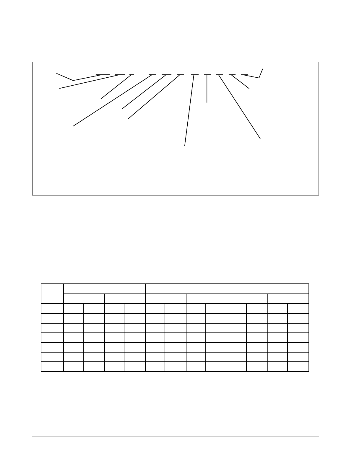
Air Conditioner Wall Mount Model Nomenclature
MODEL
NUMBER
CAPACITY
18 - 1 1/2 Ton
24 - 2 Ton
VOL TS & PHASE
A - 230/208/60/1
B - 230/208/60/3
C - 460/60/3
NOTE: For 0KW and circuit breakers (230/208 Volt) or pull disconnects (460 Volt) applications, insert 0Z in the KW field of model number.
REVISIONS
WA241–A10X XXXXA
KW
VENTILATION OPTIONS
X - Barometric Fresh Air Damper
(Standard)
B - Blank-off Plate
M - Motorized Fresh Air Damper
V - Commercial Room Ventilator -
Motorized with Exhaust
E - Economizer (Internal - Fully
Modulating with Exhaust
R - Energy Recovery Ventilator -
with Exhaust
FILTER OPTIONS
X - One Inch Throwaway
W- One Inch Washable
P - Two Inch Pleated
COLOR OPTIONS
X - Beige (Standard)
1 - White
2 - Mesa Brown
4 - Buckeye Gray
5 - Desert Brown
6 - Dark Bronze
(Standard)
CONTROL MODULES
COIL OPTIONS
X- Standard
1 - Phenolic Coated Evaporator
2 - Phenolic Coated Condenser
3 - Phenolic Coated Evaporator
and Condenser
OUTLET OPTIONS
X- Front (Standard)
T - Top on W A30 and W A36
Models
TABLE 1
ELECTRIC HEAT TABLE
sledoMAW181A-AW42A-1B-142AW
1-V0421-V8021-V0421-V8023-V0423-V802
WKSPMAHUTBSPMAHUTBSPMAHUTBSPMAHUTBSPMAHUTBSPMAHUTB
47.61056,314.41042,01
58.02560,711.81008,218.02560,711.81008,21
83.33003,728.82574,023.33003,728.82574,02
016.14031,432.63006,526.14031,432.63006,52
0.6 4.41005,025.21063,51
0.9 7.12006,037.81030,32
Manual 2100-200
Page 2
Manual 2100-200
Page 3
MIS-1262
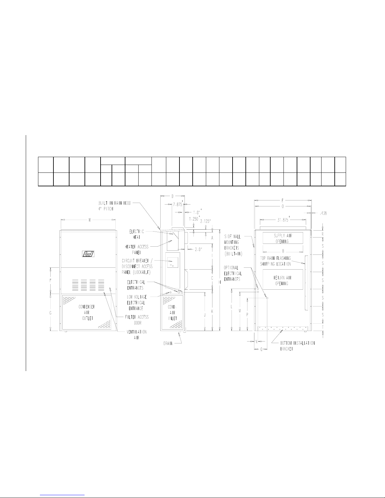
FIGURE 1
UNIT DIMENSIONS
ledoM
htdiW
)W(
htpeD
)D(
thgieH
)H(
ylppuSnruteR
EFGIJKLMNOPQRSTABCB
81AW
42AW
003.33521.71365.0788.788.9188.1188.9100.5305.8157.5265.0257.6260.8252.9200.7236.231.4360.2255.0191.400.2100.5
FRONT VIEW BACK VIEWSIDE VIEW
* Optional top outlet (factory installed only) for WA30 and WA36 models only.
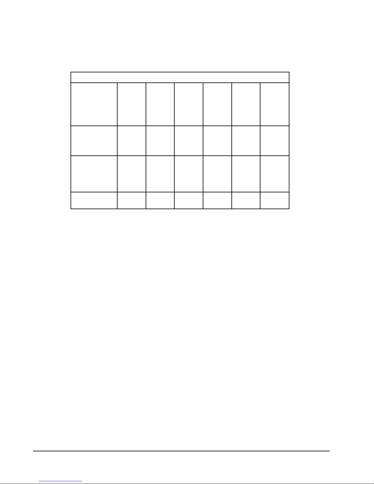
TABLE 2
ELECTRICAL SPECIFICATIONS
TIUCRICELGNIS
Q
R
mumixaM
.oN
detaR
&stloV
ledoM
esahP
Z0A,00A-181AW
50A
80A
1-802/032
01A
Z0A,00A-142AW
40A
50A
1-802/032
80A
01A
Z0B,00B-142AW
60B
Maximum size of the time delay fuse or HACR type circuit breaker for protection of field wiring
Q
conductors.
Based on 75° copper wire. All wiring must conform to the National Electrical Code and all
R
local codes.
These "Minimum Circuit Ampacity" values are to be used for sizing the field power conduc-
S
tors. Refer to the National Electric Code (latest revision), Article 310 for power conductor
sizing.
CAUTION: When more than one field power conductor circuit is run through one
conduit, the conductors must be derated. Pay special attention to note 8 of table 310
regarding Ampacity Adjustment Factors when more than three conductors are in a raceway.
3-802/032
dleiF
rewoP
stiucriC
1
1
1
1
1
1
1
1
1
1
1
muminiM
tiucriC
yticapmA
61
03
54
65
71
42
03
54
65
31
22
lanretxE
roesuF
tiucriC
rekaerB
02
03
54
06
02
52
03
54
06
51
52
dleiF
rewoP
eziSeriW
21
01
8
6
21
01
01
8
6
41
01
RS
dnuorG
eziSeriW
21
01
01
01
21
01
01
01
01
21
01
Manual 2100-200
Page 4
 Loading...