

Bard W48A2PQ, W48L2PQ, W60A2PQ, W60L2PQ, W72A2PQ Installation And Service Instructions Manual
...
INSTALLATION AND
SERVICE INSTRUCTIONS
FREE COOLING UNIT SYSTEM
WALL-MOUNTED PACKAGE
AIR CONDITIONER(S)
&
BARD-LINK™ PLC
LEAD/LAG CONTROLLER
AIR CONDITIONER MODELS
W48A2PQ W48L2PQ
W60A2PQ W60L2PQ
W72A2PQ W72L2PQ
CONTROLLER MODEL
LC5000-100
NOTE: BARD-LINK™ LC5000-100 Controller is required for operation when
multiple W***2PQ units are used.
Bard Manufacturing Company, Inc.
Bryan, Ohio 43506
www.bardhvac.com
Manual : 2100-642
Supersedes: NEW
Date: 9-15-15
Page 1 of 82

CONTENTS
SECTION 1: Installation Instructions ......................................................................................................... 7
List of Necessary Materials/Tools .........................................................................................................................8
Site Preparation .................................................................................................................................................9
Wall-Mount Unit Installation .............................................................................................................................11
Wall-Mount Unit Supply Wiring ..........................................................................................................................15
Preliminary Start-Up .........................................................................................................................................18
Bard-LinkTM Controller Installation .....................................................................................................................19
System Start-Up ..............................................................................................................................................31
SECTION 2: Service Instructions ............................................................................................................... 35
General Refrigerant Information .........................................................................................................................36
Sequence of Operation .....................................................................................................................................38
Advanced Programming ....................................................................................................................................43
Using the TEC-EYE ..........................................................................................................................................48
Componentry Specifications ..............................................................................................................................52
Maintenance and Troubleshooting ......................................................................................................................57
SECTION 3: Appendix .................................................................................................................................. 63
Appendix: LC-Series Controller and TEC-EYE Architecture ....................................................................................64
FIGURES AND TABLES
Figure 1.1 W-Series Model Nomenclature .................8
Figure 1.2 Dimensions ..........................................10
Figure 1.3 Mounting Instructions ...........................12
Figure 1.4 Electric Heat Clearance .........................13
Figure 1.5 Wall Mounting Instructions ....................13
Figure 1.6 Wall Mounting Instructions ....................14
Figure 1.7 Common Wall Mounting Installations ......14
Figure 1.8 Circuit Routing Label ............................16
Figure 1.9 WIRING: VAC Supply Wiring
Landing Points .....................................16
Figure 1.10 Adjusting the VAC Transformer ...............17
Figure 1.11 WIRING: Typical LC5000 Wiring ............19
Figure 1.12 Remote Indoor Sensor Installation ..........21
Figure 1.13 Additional Remote Sensor Installation ....22
Figure 1.14 Power and Signal Connections – Smoke ..23
Figure 1.15 WIRING: Communication Wiring ............24
Figure 1.16 WIRING: Communication Wiring:
Controller Termination ...........................25
Figure 1.17 WIRING: Communication Wiring:
1st Unit Termination .............................26
Figure 1.18 WIRING: Communication Wiring:
Additional Unit Termination ...................27
Figure 1.19 Controller Circuit Install ........................28
Figure 1.20 Controller Grounding Posts ....................28
Figure 1.21 WIRING: LC5000 Wiring Diagram ..........30
Figure 1.22 Clock/Scheduler Menu ..........................31
Figure 1.23 Total Units Displayed ............................31
Figure 1.24 Bard-LinkTM Controller and TEC-EYE .......32
Figure 1.25 Status Display Showing Units "Online" ....33
Figure 1.26 Status Display Showing Units "Offline" ....33
Figure 1.27 Board Switch Display ............................33
Figure 1.28 Executing Run Test ...............................34
Figure 2.1 Refrigerant Sight Glass .........................37
Figure 2.2 Wall-Mount Unit Control Board ..............39
Figure 2.3 Controller Board and Terminal Block .......41
Figure 2.4 LC -5000 Controller Control Board .........41
Figure 2.5 Free Cooling Damper Operation ..............42
Figure 2.6 Bard-LinkTM Controller Display ...............43
Figure 2.7 Controller Status Display .......................44
Figure 2.8 Total Units Displayed ............................44
Figure 2.9 Status Display Showing Units "Online" ....45
Figure 2.10 Status Display Showing Units "Offline" ....45
Figure 2.11 Board Switch Display ............................45
Figure 2.12 Executing Run Test ...............................45
Figure 2.13 TEC-EYE Display ..................................48
Figure 2.14 TEC-EYE Connection to Unit Control ......48
Figure 2.15 TEC-EYE Status Display ........................49
Figure 2.16 Local and Current Cool/Heat Setpoints ....49
Figure 2.17 Executing Run Test ...............................50
Figure 2.18 Fan Blade Setting .................................54
Figure 2.19 Dirty Filter Switch and Airflow Switch .....54
Figure 2.20 High Pressure Relay Circuit ...................54
Figure 2.21 Unit Control Panel ................................55
Figure 2.22 WIRING: Unit Wiring Diagram ................56
Table 1.1 Electrical Specifications ..........................15
Table 1.2 Terminal Block Index ...............................29
Table 1.3 Controller Default Settings .......................34
Table 2.1 Nominal Pressures ..................................37
Table 2.2 Controller Default Settings .......................42
Table 2.3 Controller Programmable Features ............47
Table 2.4 Temp vs. Resistance of Temp Sensor. ........52
Table 2.5 Indoor Blower Performance ......................54
Manual 2100-642
Page 2 of 82
GENERAL INFORMATION
FREE COOLING UNIT SYSTEM
The Bard Free Cooling Unit system is composed of wall-mounted air conditioners matched with a Bard-LinkTM PLC
lead/lag controller or thermostat. The wall mounts are specifically engineered for telecom motor control center rooms.
If only one wall-mounted air conditioner is being used, it can be matched with either the Bard-Link
TM
controller or thermostat. If more than one wall mount is installed, the Bard-Link
PLC lead/lag controller must be
matched with the air conditioning units.
TM
NOTE: The Bard-Link
PLC lead/lag controller and wall-mount units are designed specifically to work together. The
PLC controller cannot run other Bard models or other brands of systems, nor can other controllers run the
PLC wall-mount units. They are a complete system, and must be used together.
WALL-MOUNT AIR CONDITIONER UNITS
The W-Series units operate on VAC power.
with ability to exhaust the same amount through the unit itself without any additional relief openings in the shelter.
Each of these units are fully charged with refrigerant and have auxilliary heat installed.
TM
BARD-LINK
PLC CONTROLLER
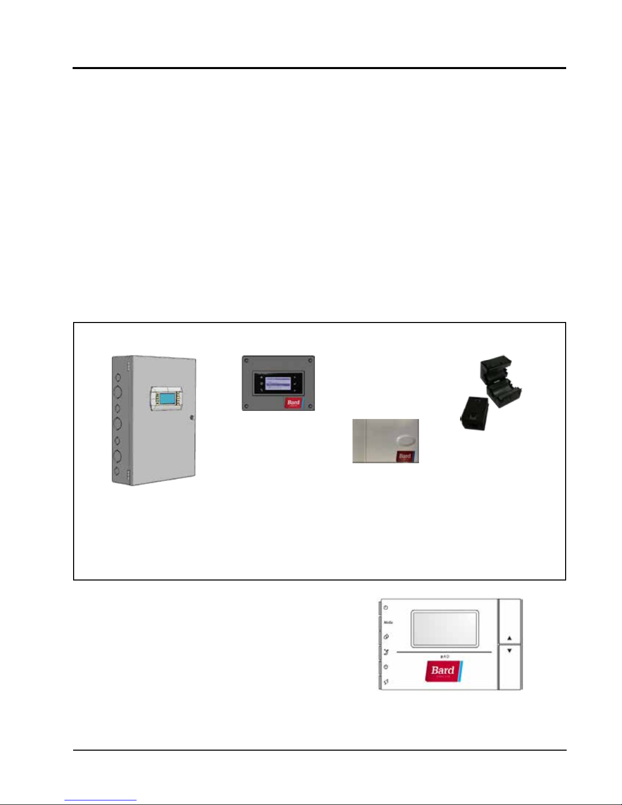
LC5000-100 (controller and accessories included with controller shown below).
The units will supply 100% of rated cooling airflow in free cooling mode
LC5000-100 Series
TM
PLC lead/lag
TEC-EYE Hand-Held
Diagnostic Tool
Bard P/N 8301-059
Communication
Programmable Logic
Controller
EMI Filters
Bard P/N 8301-055
Remote Temperature/
Humidity Sensor*
Bard P/N 8301-058
* One remote temperature/humidity sensor is included with the LC-5000-100 controller. If the site in which
the LC-5000-100 controller will be used has more than one zone (maximum three zones per LC-5000-100),
additional remote temperature/humidity sensors (one sensor per zone) will need to be purchased and installed
in the additional zones. One additional temperature-only sensor may also be used in Zone 1 but will also need
to be purchased separately.
SINGLE UNIT OPERATION
Bard thermostat 8403-077 or 8403-078 can be used in
place of the BARD-LINK
W-Series wall mount air conditioner is being installed.
If using a thermostat instead of the PLC controller, the
alarm logging and remote communication capabilities
of the controller will not be available. See page 20 for
information on installing and setting up the thermostat
for single unit operation.
TM
PLC controller when only one
Manual 2100-642
Page 3 of 82

The equipment covered in this manual is to be installed
by trained, experienced service and installation
technicians.
The refrigerant system is completely assembled and
charged. All internal wiring is complete.
The unit is designed for use with or without duct work.
Flanges are provided for attaching the supply and return
ducts.
These instructions explain the recommended method
to install the air cooled self-contained unit and the
electrical wiring connections to the unit.
These instructions and any instructions packaged with
any separate equipment required to make up the entire
air conditioning system should be carefully read before
beginning the installation. Note particularly “Starting
Procedure” and any tags and/or labels attached to the
equipment.
While these instructions are intended as a general
recommended guide, they do not supersede any national
and/or local codes in any way. Authorities having
jurisdiction should be consulted before the installation is
made. See Additional Publications for information
on codes and standards.
Sizing of systems for proposed installation should
be based on heat loss calculation made according to
methods of Air Conditioning Contractors of America
(ACCA). The air duct should be installed in accordance
with the Standards of the National Fire Protection
Association for the Installation of Air Conditioning and
Ventilating Systems of Other Than Residence Type,
NFPA No. 90A, and Residence Type Warm Air Heating
and Air Conditioning Systems, NFPA No. 90B. Where
local regulations are at a variance with instructions,
installer should adhere to local codes.
Shipping Damage
Upon receipt of equipment, the cartons should be
checked for external signs of shipping damage. If
damage is found, the receiving party must contact
the last carrier immediately, preferably in writing,
requesting inspection by the carrier’s agent.
These units must remain in upright position at all
times.
ADDITIONAL PUBLICATIONS
These publications can help when installing the
furnace. They can usually be found at the local library
or purchased directly from the publisher. Be sure to
consult the current edition of each standard.
National Electrical Code ...................... ANSI/NFPA 70
Standard for the Installation of Air Conditioning
and Ventilating Systems ...................ANSI/NFPA 90A
Standard for Warm Air Heating
and Air Conditioning Systems ............ANSI/NFPA 90B
Load Calculation for Residential Winter
and Summer Air Conditioning ............. ACCA Manual J
Duct Design for Residential Winter and Summer
Air Conditioning and Equipment Selection
....................................................... ACCA Manual D
For more information, contact these publishers:
Air Conditioning Contractors of America (ACCA)
1712 New Hampshire Ave. N.W.
Washington, DC 20009
Telephone: (202) 483-9370
Fax: (202) 234-4721
American National Standards Institute (ANSI)
11 West Street, 13th Floor
New York, NY 10036
Telephone: (212) 642-4900
Fax: (212) 302-1286
American Society of Heating, Refrigeration and Air
Conditioning Engineers, Inc. (ASHRAE)
1791 Tullie Circle, N.E.
Atlanta, GA 30329-2305
Telephone: (404) 636-8400
Fax: (404) 321-5478
National Fire Protection Association (NFPA)
Batterymarch Park
P. O. Box 9101
Quincy, MA 02269-9901
Telephone: (800) 344-3555
Fax: (617) 984-7057
Manual 2100-642
Page 4 of 82
ANSI Z535.5 Definitions:
DANGER: Indicate[s] a hazardous situation which, if
not avoided, will result in death or serious injury. The
signal word “DANGER” is to be limited to the most
extreme situations. DANGER [signs] should not be used
for property damage hazards unless personal injury risk
appropriate to these levels is also involved.
WARNING: Indicate[s] a hazardous situation which,
if not avoided, could result in death or serious injury.
WARNING [signs] should not be used for property
damage hazards unless personal injury risk appropriate
to this level is also involved.
CAUTION: Indicate[s] a hazardous situation which, if
not avoided, could result in minor or moderate injury.
CAUTION [signs] without a safety alert symbol may be
used to alert against unsafe practices that can result in
property damage only.
NOTICE: [this header is] preferred to address practices
not related to personal injury. The safety alert symbol
shall not be used with this signal word. As an
alternative to “NOTICE” the word “CAUTION” without
the safety alert symbol may be used to indicate a
message not related to personal injury.
!
WARNING
Electrical shock hazard.
Have a properly trained individual perform
these tasks.
Failure to do so could result in electric shock
or death.
!
WARNING
Fire hazard.
Maintain minimum 1/4" clearance between the
supply air duct and combustible materials in
the rst 3' feet of ducting.
Failure to do so could result in re causing
damage, injury or death.
!
WARNING
Heavy item hazard.
Use more than one person to handle unit.
Failure to do so could result in unit damage or
serious injury.
!
CAUTION
Cut hazard.
Wear gloves to avoid contact with sharp
edges.
Failure to do so could result in personal injury.
Manual 2100-642
Page 5 of 82

Manual 2100-642
Page 6 of 82

SECTION 1:
INSTALLATION
INSTRUCTIONS
Manual 2100-642
Page 7 of 82
LIST OF NECESSARY MATERIALS/TOOLS
Additional hardware and miscellaneous supplies are needed for installation. These items are field supplied and must
be sourced before installation. This list also includes tools needed for installation.
LIST OF MATERIALS/TOOLS
• Personal protective equipment/safety devices
• Supply/return grilles
• Field-fabricated sleeves (if necessary)
• 5/16" diameter anchor/carriage/lag bolts
• 7/8" diameter washers
• Caulking materials
• Miscellaneous hand and power tools and jobsite or
shop materials
• Lifting equipment with the necessary capacity and
rigging to safely move/install the systems
• Electrical supplies
- Various size circuit breakers for the shelter
AC breaker box (see Table 1.1: Electrical
Specifications on page 15)
- High-voltage wire of various gauges
(see Table 1.1)
- Communication wire: 2-wire, 18 gauge,
shielded with drain
- 5-wire, 18 gauge shielded cable with drain for
remote temperature and humidity sensor
-
- Miscellaneous electrical supplies including
CAT 6 Ethernet cable of field-determined length
(for remote communication, if applicable)
rigid/flexible conduit and fittings, junction
boxes, wire connectors and supports
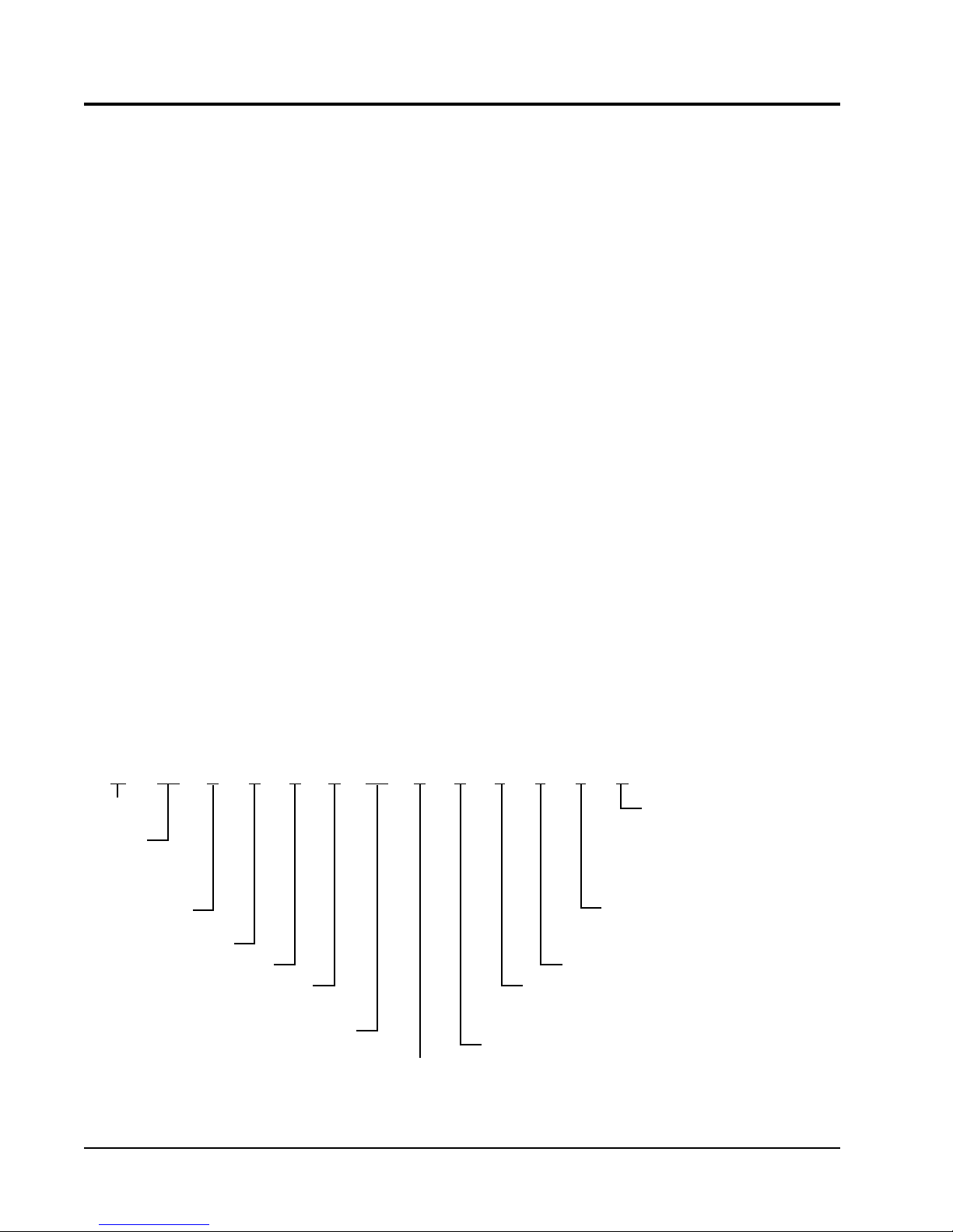
FIGURE 1.1
W-Series Wall-Mount Unit Model Nomenclature
W 72 A 2 P Q 15 5 P X X X D
MODEL
SERIES
CAPACITY
48 – 4 Ton
60 – 5 Ton
72 – 6 Ton
A – Right Hand
L – Left Hand
REVISION
* 3 Stage Heat: 6, 9 or 15 KW
Manual 2100-642
Page 8 of 82
PLC
VOLTS & PHASE
Q – 575-60-3
KW
15 – 15 KW
3 Stage*
ECONOMIZER
Default Enthalpy,
Convert to DB only
COLOR OPTIONS
X – Beige
1 – White
4 – Buckeye Gray
FILTER OPTIONS
P – 2" Pleated (MERV 8)
M – 2" Pleated (MERV 11)
X – 1" Fiberglass (MERV 2)
(Standard)
COIL OPTIONS
X – Standard
3 – Phenolic Coated Evaporator and Condenser for
coastal or other severe duty environments
SPECIAL FEATURES
CONTROL MODULES
D – Airflow Switch, Dirty Filter Switch, High
Pressure Switch, Low Pressure Switch,
Compressor Control Module, Low Ambient
Control, Evaporator Freeze Protection,
Refrigerant Alarm (from PLC) and
Compressor Crankcase Heater
SITE PREPARATION
NEW SHELTER INSTALLATION VS.
RETROFIT INSTALLATION
These installation instructions cover both new shelter
installations and retrofit installations. Each installation
is unique and may require special accomodations and
modifications. Although Bard Manufacturing follows a
long-established tradition of manufacturing equipment
using industry standard dimensions for building
penetration, it is occasionally necessary to move or
enlarge supply and return openings when replacing
non-standardized equipment in a retrofit application.
MINIMUM CLEARANCE
Wall-mount air conditioners are available in both righthand access models and left-hand access models.
Right-hand access models have the heat strip access
panel, external circuit breakers access panel and
internal controls access panel on the right side of the
unit. Left-hand access models are a mirror image of the
right-hand access models, and allow two wall-mount
units to be placed in relatively close proximity and yet
still allow complete acess for maintenance and repair.
On side-by-side installations, maintain a minimum of
26" clearance on control side to allow access to control
panel and heat strips, and to allow proper airflow to the
outdoor coil. For installations where units are installed
with both control panels facing each other (inward),
maintain a minimum of 36" clearance to allow access.
Additional clearance may be required to meet local or
national codes.
Care should be taken to ensure that the recirculation
and obstruction of condenser discharge air does not
occur. Recirculation of condenser discharge air can
be from either a single unit or multiple units. Any
object such as shrubbery, a building or a large object
can cause obstructions to the condenser discharge air.
Recirculation or reduced airflow caused by obstructions
will result in reduced capacity, possible unit pressure
safety lockouts and reduced unit service life.
For units with blow through condensers, such as
theses wall-mount units, it is recommended there be
a minimum distance of 10' between the front of the
unit and any barrier or 20' between the fronts of two
opposing (facing) units.
CLEARANCE TO COMBUSTIBLES
!
WARNING
Fire hazard.
Maintain minimum 1/4" clearance between the
supply air duct and combustible materials in
the rst 3' feet of ducting.
Failure to do so could result in re causing
damage, injury or death.
The unit itself is suitable for 0" clearance, but the
supply air duct flange and the first 3' of supply air duct
require a minimum of 1/4" clearance to combustible
material. However, it is generally recommended that
a 1" clearance is used for ease of installation and
maintaining the required clearance to combustible
material. See Figure 1.3 on page 12 for details on
opening sizes.
Minimum Clearances Required to
Combustible Materials
MODELS
All covered by this
manual
SUPPLY AIR DUCT
FIRST 3'
1/4" 0"
CABINET
MODEL IDENTIFICATION
Identify the specific model using the model
nomenclature information found in Figure 1.1 and/
or model/serial tag found on the unit on the opposite
side of the control and access panels. See Figure 1.2
on page 10 for dimensions and critical installation
requirements.
Clearances Required for Service Access
and Adequate Condenser Airflow
MODELS LEFT SIDE RIGHT SIDE
All covered by this manual 26" 26"
Units with control panels
facing each other (inward)
36" between units
Manual 2100-642
Page 9 of 82
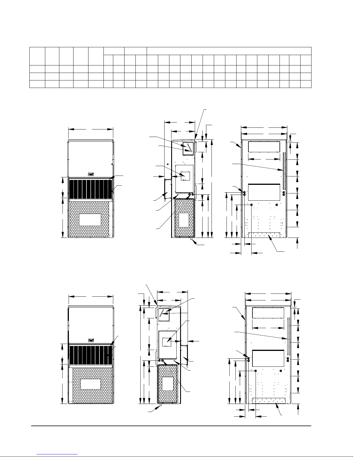
FIGURE 1.2
BACK VIEW
DOOR
AIR
VENTILIATION
VENT HOOD
Cond.
Air
Inlet
FRONT VIEW
G
F
W
ELECTRIC HEAT
Top Rain
Flashing
Shipping
Location
PANEL
ELECTRICAL
ENTRANCE
(LOCKABLE)
4° PITCH
RAIN HOOD
BUILT IN
VENT HOOD
LOW VOLTAGE
ACCESS
HEATER
ENTRANCE
ACCESS PANEL
DISCONNECT
DRAIN
C. BREAKER/
HIGH VOLTAGE
ELECTRICAL
SIDE VIEW
DT
KCJ
H
7"
D
2.13
I
A
BUILT IN
(Built In)
OPENING
RETURN AIR
OPENING
SUPPLY AIR
Brackets
Mounting
Optional
Entrances
Electrical
Side Wall
BOTTOM
INSTALLATION
BRACKET
BACK VIEW
S
B
P
M
L
N
E
O
T
S
S
S
S
R
Q
Air Outlet
Condenser
Dimensions of Basic Unit for Architectural and Installation Requirements (Nominal)
Depth
(D)
Depth
Total
(DT)
Height
Width
Model
W48A/L 42.075 22.432 22.432 93.000 9.88 29.88 15.88 29.88 43.88 13.56 37.00 30.00 40.81 35.06 42.81 40.56 3.37 43.00 31.00 10.00 1.44 16.00 10.00
W60A/L 42.075 22.432 22.432 93.000 9.88 29.88 15.88 29.88 43.88 13.56 37.00 30.00 40.81 35.06 42.81 40.56 3.37 43.00 31.00 10.00 1.44 16.00 10.00
W72A/L 42.075 22.432 22.432 93.000 9.88 29.88 15.88 29.88 43.88 13.56 37.00 30.00 40.81 35.06 42.81 40.56 3.37 43.00 31.00 10.00 1.44 16.00 10.00
(W)
Supply Return
(H)
A B C B E F G I J K L M N O P Q R S T
All dimensions are in inches. Dimensional drawings are not to scale.
BUILT IN
RAIN HOOD
4° PITCH
A
I
H
KCJ
DRAIN
HEATER
ACCESS
PANEL
C. BREAKER/
DISCONNECT
ACCESS PANEL
(LOCKABLE)
7"
VENT HOOD
LOW VOLTAGE
ELECTRICAL
ENTRANCE
HIGH VOLTAGE
ELECTRICAL
ENTRANCE
2.13
Side Wall
Mounting
Brackets
(Built In)
Top Rain
Flashing
Shipping
Location
Optional
Electrical
Entrances
Side Wall
Mounting
Brackets
(Built In)
L
M
N
Top Rain
Flashing
Shipping
Location
Optional
Electrical
Entrances
L
M
P
P
SUPPLY AIR
OPENING
RETURN AIR
OPENING
Q
RETURN AIR
E
O
B
MIS-3618A
E
O
SUPPLY AIR
OPENING
B
OPENING
W**A
RIGHT
HAND
UNIT
W**A
LEFT
HAND
UNIT
F
G
F
G
W
Condenser
Air Outlet
FRONT VIEW
W
Condenser
Air Outlet
VENT HOOD
DOOR
VENTILIATION
AIR
VENT HOOD
DOOR
VENTILIATION
AIR
HEATER
ACCESS
PANEL
ELECTRIC HEAT
C. BREAKER/
DISCONNECT
ACCESS PANEL
(LOCKABLE)
7"
VENT HOOD
LOW VOLTAGE
ELECTRICAL
ENTRANCE
HIGH VOLTAGE
ELECTRICAL
ENTRANCE
RAIN HOOD
4° PITCH
2.13
A
I
H
C
J
K
D
Cond.
Air
Inlet
DT
D
Cond.
Air
Inlet
SIDE VIEW
DT
ELECTRIC HEAT
R
S
S
S
S
S
T
BOTTOM
INSTALLATION
BRACKET
R
S
S
S
S
S
T
BACK VIEW
Manual 2100-642
Page 10 of 82
DRAIN
SIDE VIEW
N
Q
BACK VIEW
BOTTOM
INSTALLATION
BRACKET

WALL-MOUNT UNIT INSTALLATION
MOUNTING THE UNITS
!
WARNING
Heavy item hazard.
Use more than one person to handle unit.
Failure to do so could result in unit damage or
serious injury.
NOTE: It may be best to spot some electrical knockouts
(such as those located on the back of the wallmount unit) before units are mounted and access is
unavailable or limited (see Figure 1.2 to locate prepunched knockouts).
Two holes for the supply and return air openings must
be cut through the wall as shown in Figure 1.3 on page
12. On wood frame walls, the wall construction must
be strong and rigid enough to carry the weight of the
unit without transmitting any unit vibration. Concrete
block walls must be thoroughly inspected to insure that
they are capable of carrying the weight of the installed
unit.
In retrofit (unit replacement) installations, the openings
cut for the original equipment may not line up exactly
with needs of this installation. Modifications may need
to be made, such as increasing or decreasing the size
of the wall cutouts. The existing bolt placement may
not line up in which case the original bolts would need
to be removed or cut away.
1. These units are secured by wall mounting flanges
which secure the unit to the outside wall surface at
both sides. A bottom mounting bracket, attached
to skid for shipping, is provided for ease of
installation, but is not required.
2. The unit itself is suitable for 0" clearance, but the
supply air duct flange and the first 3' of supply
air duct require a minimum of 1/4" clearance to
combustible material. However, it is generally
recommended that a 1" clearance is used for
ease of installation and maintaining the required
clearance to combustible material. See Figure 1.3
for details on opening sizes.
3. Locate and mark lag bolt locations and location for
optional bottom mounting bracket, if desired (see
Figure 1.3).
4. Mount bottom mounting bracket (if used).
5. If desired, hook top rain flashing (attached to frontright of supply flange for shipping) under back
bend of top.
6. Position unit in opening and secure with 5/16" lag/
anchor/carriage bolts; use 7/8" diameter flat washers
on the lag bolts. It is recommended that a bead
of silicone caulking be placed behind the side
mounting flanges.
7. Secure optional rain flashing to wall and caulk
across entire length of top (see Figure 1.3).
8. For additional mounting rigidity, the return air
and supply air frames or collars can be drilled
and screwed or welded to the structural wall itself
(depending upon wall construction). Be sure to
observe required clearance if combustible wall.
9. A plastic drain hose extends from the drain pan at
the top of the unit down to the unit base. There are
openings in the unit base for the drain hose to pass
through. In the event the drain hose is connected
to a drain system of some type, it must be an open
or vented type system to assure proper drainage.
Manual 2100-642
Page 11 of 82
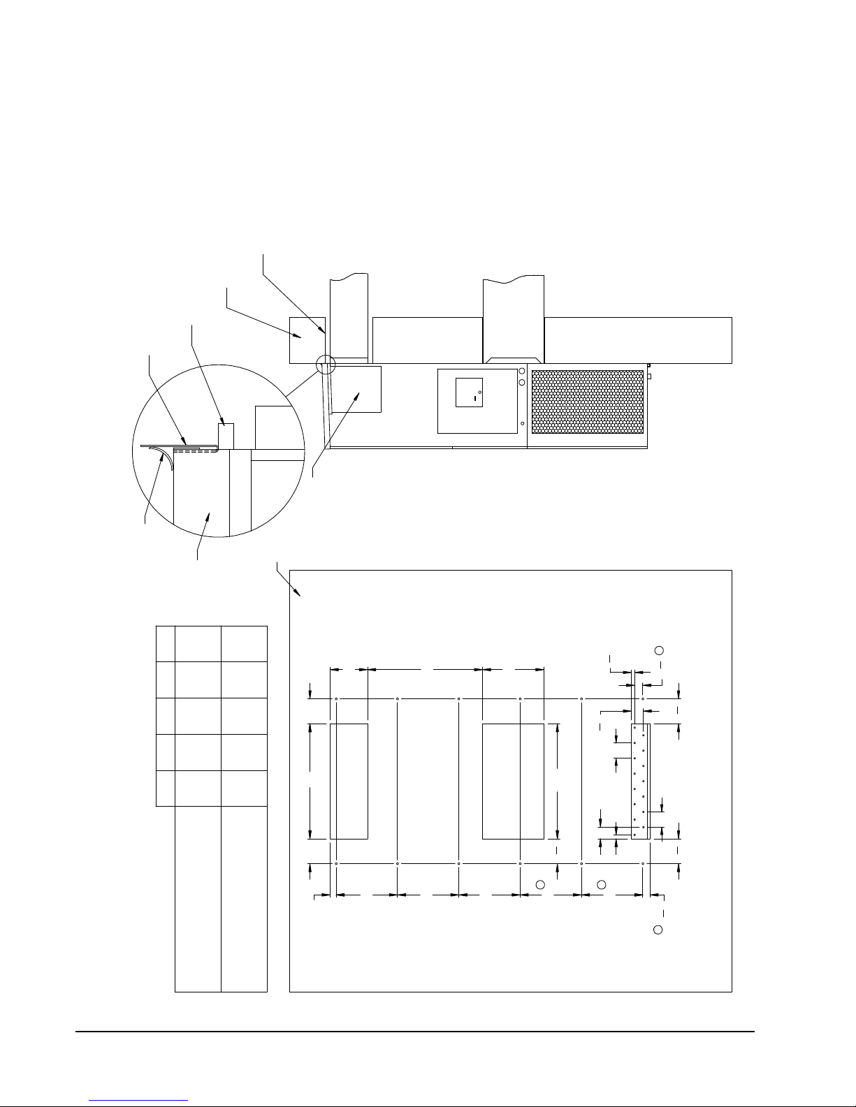
SUPPLIED
RAIN FLASHING
FOAM AIR SEAL
WALL STRUCTURE
1/4" CLEARANCE ON ALL
FOUR SIDES OF SUPPLY
AIR DUCT IS REQUIRED
MATERIALS
FROM COMBUSTABLE
PANEL
DUCT
SUPPLY AIR
RETURN AIR
OPENING
NOTES:
IT IS RECOMMENDED THAT A BEAD OF
SILICONE CAULKING BE PLACED BEHIND
THE SIDE MOUNTING FLANGES AND UNDER
MIS-3354
TOP FLASHING AT TIME OF INSTALLATION.
Right Side View
TOP.
FIGURE 1.3
SEAL WITH BEAD
OF CAULKING ALONG
ENTIRE LENGTH OF
Mounting Instructions
A B C D E
HEATER ACCESS
WALL
TOP
29
2
B
E
16"
6 1/4 1 1/4 29 3/4
10 1/2
30 1/2
32 12 5 1/2
A CC
Supply Opening
Return Opening
30"
"
1
2
6
"
7
8
"
1
8
3
4"
3"
3
"
1
8
2
"
1
2
Typ.
1"
4"
Typ.
" 6
1
2
6
Wall Opening and Hole Location View
1
D
16"
16"
16"
16"
1
16"
"
7
8
1
2
COMBUSTIBLE MATERIALS
1/4" MIN. CLEARANCE FROM
REQUIRED DIMENSIONS TO MAINTAIN
REQUIRED DIMENSIONS TO MAINTAIN
RECOMMENDED 1" CLEARANCE FROM
COMBUSTIBLE MATERIALS
Manual 2100-642
Page 12 of 82
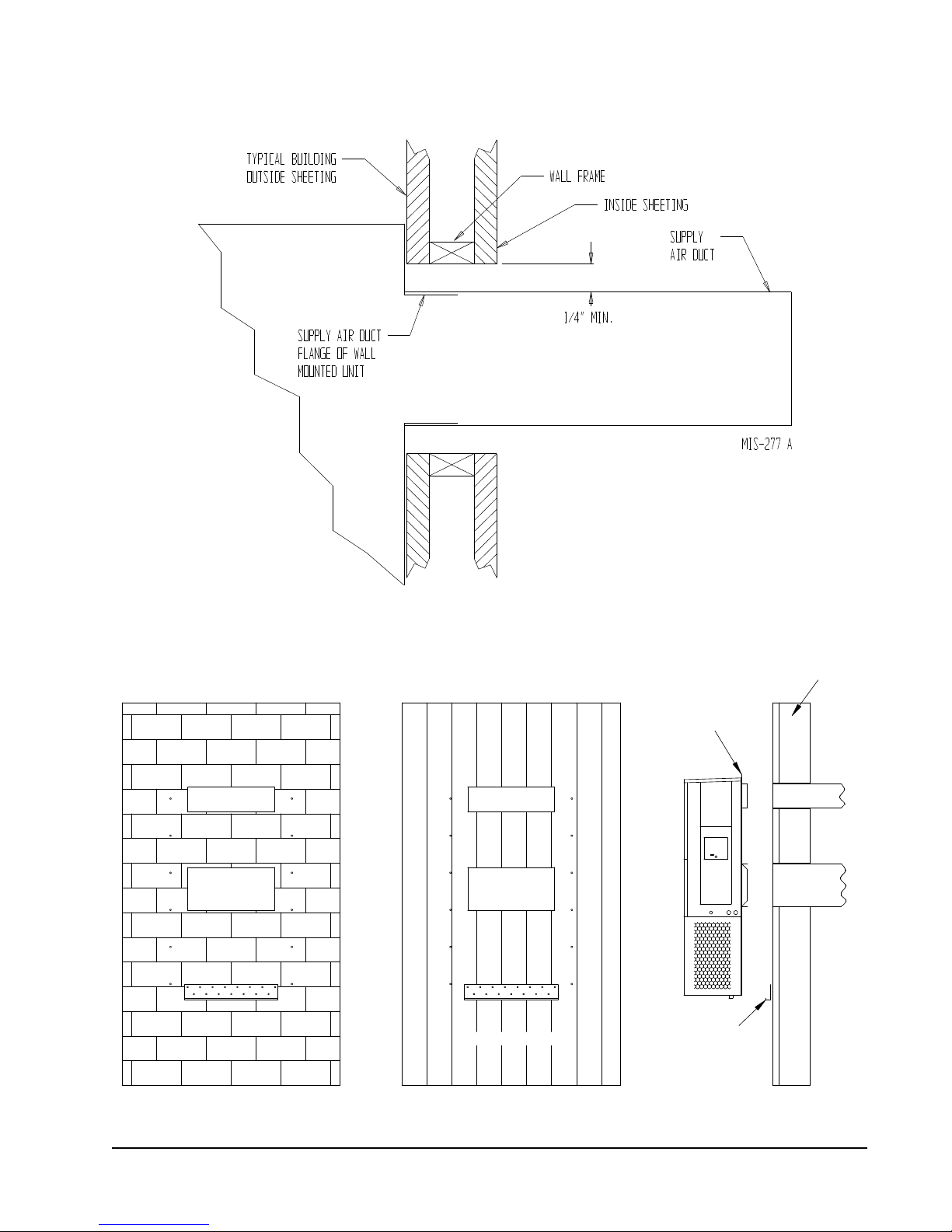
FIGURE 1.4
DUCT
OPENING
RETURN AIR
SUPPLY AIR
WOOD FRAME WALL INSTALLATION
OPENING
WALL BEFORE
MOUNT ON UNIT
OPENING
BEFORE INSTALLATION
BOTTOM MOUNTING
CONCRETE BLOCK WALL INSTALLATION
BRACKET. MOUNT ON
OPENING
WOOD OR STEEL SIDING
OPENING
INSTALLING UNIT.
RETURN AIR
WALL STRUCTURE
RETURN AIR
SUPPLY AIR
FACTORY SUPPLIED
RAIN FLASHING.
SUPPLY AIR
MIS-548 A
SIDE VIEW
Electric Heat Clearance
Wall Mounting Instructions
See FIGURE 2 – Mounting Instructions
FIGURE 1.5
Manual 2100-642
Page 13 of 82
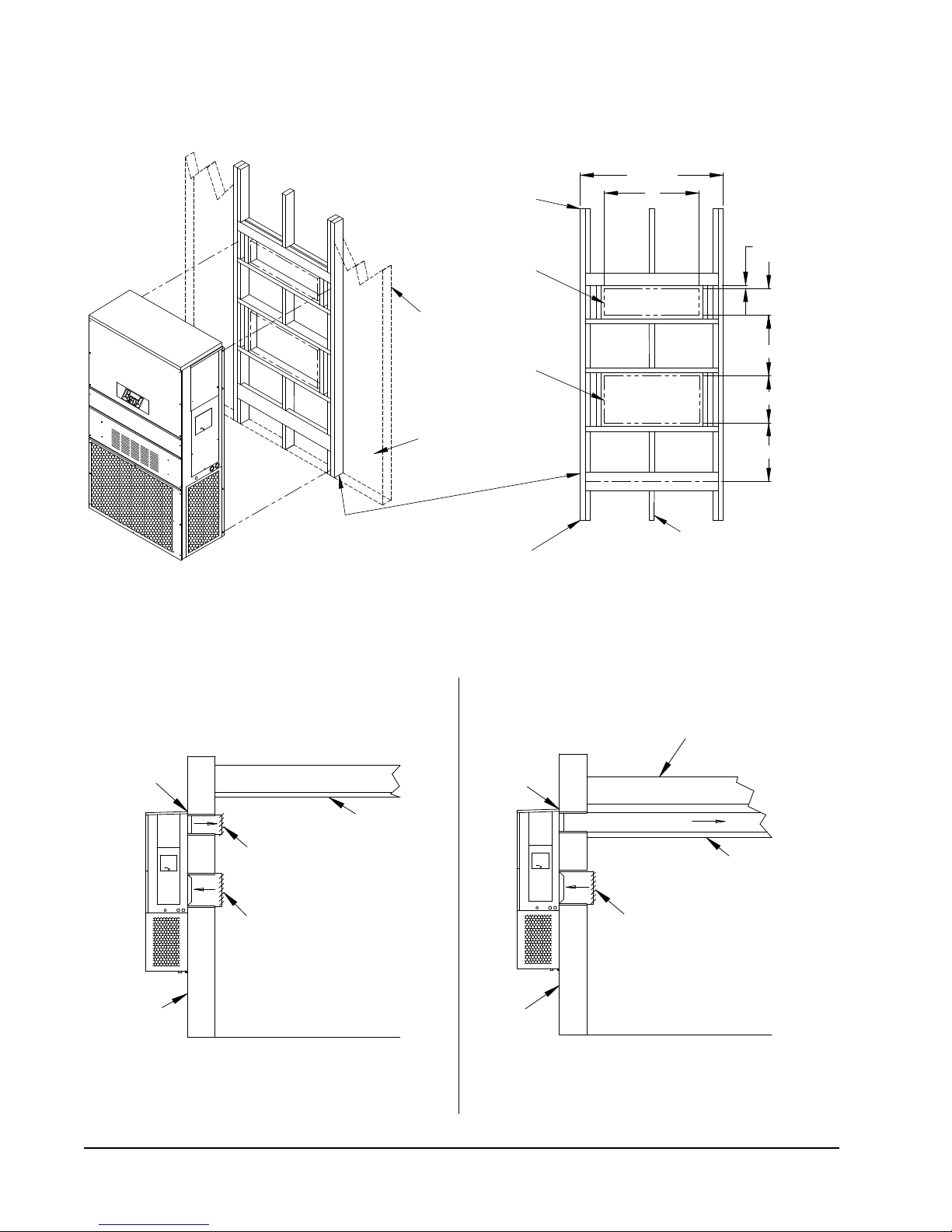
FIGURE 1.6
I
A
C
K
E + 1.000
B
1.000
SUPPLY DUCT
OVER FRAME
INTERIOR FINISHED WALL
ALL AROUND DUCT
FRAMING MATERIAL
EXTERIOR FINISH WALL
OPENING
FOR ACTUAL DIMENSIONS.
2 x 4'S, 2 x 6'S &/OR
STRUCTURAL STEEL
ATTACH TO TOP
1.000" CLEARANCE
1.000" CLEARANCE
PLATE OF WALL
C
SEE UNIT DIMENSIONS, FIGURE 2,
OPENING
RETURN DUCT
2 x 6
ATTACH TO BOTTOM
OVER FRAME
PLATE OF WALL
L
THIS STRUCTURAL MEMBER
LOCATED TO MATCH STUD
SPACING FOR REST OF WALL.
A SECOND MEMBER MAY BE
REQUIRED FOR SOME WALLS.
MIS-549 B
ALL AROUND DUCT
SUPPLY DUCT MAY BE LOCATED IN AN ATTIC
OPENING W/ GRILLE
SUPPLY AIR DUCT
RAFTERS
RAFTERS
RETURN AIR
OPENING W/ GRILLE
DUCTED SUPPLY
OR BELOW CEILING RAFTERS AS SHOWN
FINISHED CEILING SURFACE
RAIN
FLASHING
RAIN
FLASHING
RETURN AT UNITNO DUCT
RETURN AIR
FINISHED CEILING SURFACE
FREE AIR FLOW
OUTSIDE
WALL
OUTSIDE
WALL
SUPPLY AIR DUCT
W/ GRILLE
Wall Mounting Instructions
FIGURE 1.7
Common Wall Mounting Installations
Manual 2100-642
Page 14 of 82
WALL-MOUNT UNIT SUPPLY WIRING
All models covered by this installation
instruction require VAC utility power to run
the compressor, heat, outdoor fan motor,
indoor blower and free cooling damper.
!
WARNING
Electrical shock hazard.
Have a properly trained individual perform
these tasks.
Failure to do so could result in electric shock
or death.
Refer to the unit rating plate or Table 1.1 for wire
sizing information and maximum fuse or circuit breaker
size. Each outdoor unit is marked with a “Minimum
Circuit Ampacity”. The field wiring used must be sized
to carry that amount of current. All models are suitable
only for connection with copper wire. Each unit and/or
wiring diagram will be marked “Use Copper Conductors
Only”. These instructions must be adhered to. Refer
to the National Electrical Code (NEC) for complete
current carrying capacity data on the various insulation
grades of wiring material. All wiring must conform to
NEC and all local codes.
TABLE 1.1
Electrical Specifications
AC POWER CIRCUIT
Model
W48A2PQ15/W48L2PQ15 575-60-3 21 25 10 10
W60A2PQ15/W60L2PQ15 575-60-3 21 25 10 10
W72A2PQ15/W72L2PQ15 575-60-3 24 25 10 10
These “Minimum Circuit Ampacity” values are to be used for sizing the field power conductors. Refer to the National Electric Code (latest
version), Article 310 for power conductor sizing.
CAUTION: When more than one field power circuit is run through one conduit, the conductors must be derated. Pay special attention to
note 8 of Table 310 regarding Ampacity Adjustment Factors when more than three (3) current carrying conductors are in a
raceway.
Maximum size of the time delay fuse or circuit breaker for protection of field wiring conductors.
Based on 75°C copper wire. All wiring must conform to the National Electric Code and all local codes.
IMPORTANT: While this electrical data is presented as a guide, it is important to electrically connect properly sized fuse and conductor
wires in accordance with the National Electrical Code and all local codes.
Rated Volts,
Hertz & Phase
Minimum Circuit
Ampacity
Maximum
External Fuse or
Circuit Breaker
Field Power
Wire Size
Ground
Wire Size
Manual 2100-642
Page 15 of 82
The electrical data lists fuse and wire sizes (75°C
NOTICE / AVIS
WHITE 3/16" LETTERING
copper) for all models including the most commonly
used heater sizes. Also shown are the number of field
power circuits required for the various models with
heaters.
The unit rating plate lists a “Maximum Time Delay
Relay Fuse” or circuit breaker that is to be used with
the equipment. The correct size must be used for
proper circuit protection and also to assure that there
will be no nuisance tripping due to the momentary high
starting current of the compressor motor.
Route all field wires to the right of the wire shield as
shown in the circuit routing label found in Figure 1.8
(and also on the wall-mount units).
Factory
Wiring
FIGURE 1.9
VAC Supply Wiring Landing Points
Field
Wiring
FIGURE 1.8
Circuit Routing Label
ROUTE ALL HIGH VOLTAGE FIELD
WIRES TO THE RIGHT OF THE WIRE
SHIELD AS SHOWN
ACHEMINER LES FILS HAUTE
TENSION SUR LA DROITE VERS LA
PROTECTION, COMME INDIQUÉ
CIRCUIT BREAKER
/DISJONCTEUR
WIRE SHIELD /
PROTECTION
CONTACTOR /
COMPRESSOR
COMPRESSEUR
CONTACTEUR DU
7961-393
See Figure 1.9 to reference VAC landing points.
The disconnect access door on this unit may be locked
to prevent unauthorized access to the disconnect. To
convert for the locking capability, bend the tab located
in the bottom left-hand corner of the disconnect
opening under the disconnect access panel straight
out. This tab will now line up with the slot in the door.
When shut, a padlock may be placed through the hole
in the tab preventing entry.
NOTE: Right-hand access model wiring landing points
are shown here; left-hand access models will
mirror this image.
IMPORTANT
277/380/575 1-phase and 3-phase equipment
use dual primary voltage transformers. All
equipment leaves the factory wired on 575V tap.
It is very important that the correct voltage tap
is used.
Manual 2100-642
Page 16 of 82
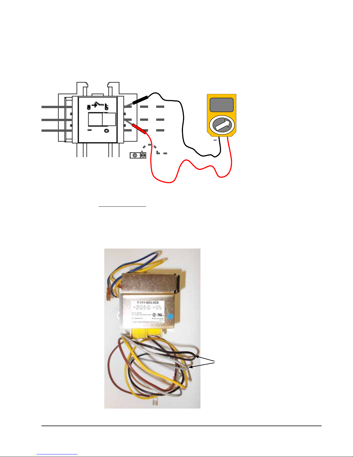
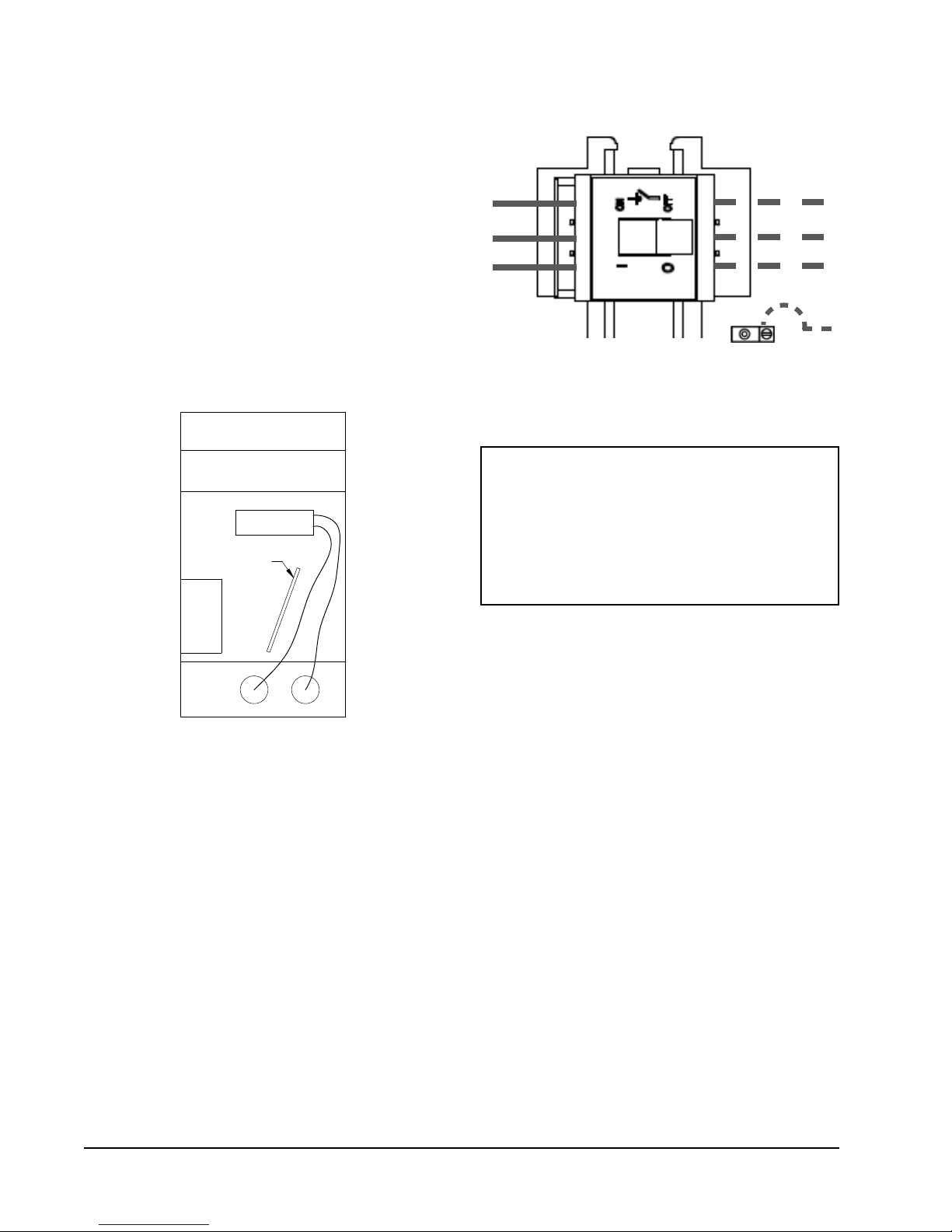
Adjusting the VAC Transformer
575VAC
It is very important that the transformer is wired for the correct 575V voltage
1. Verify incoming AC voltage: Multimeter set to VAC
Shelter supply breaker in ON position Bard
system breaker in OFF position
575V Three Phase Voltage Range:
546VAC – 632VAC
FIGURE 1.10
+
2. Confirm correct wires are connected: For 575V, the gray (575) and black (common) transformer wires must be used.
Gray and black wires
must be used
Manual 2100-642
Page 17 of 82
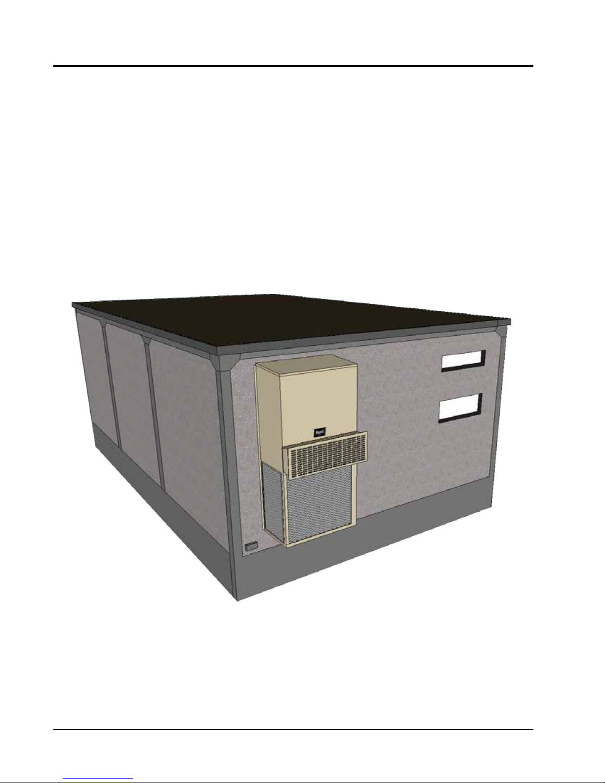
PRELIMINARY START-UP
RUNNING IN STAND ALONE (ORPHAN) MODE
With the AC breakers turned on, each W-Series wall-mount system has the capability to run without the PLC
controller attached—this feature is called Stand Alone or Orphan Mode, and it basically keeps the shelter between
60°F and 77°F by the use of the factory-installed return air sensor in each wall-mount unit.
During installation, this allows deactivation of one of the two existing, older wall-mount units, while keeping the
shelter cool with the other unit still operating. Once the first of the two Bard wall-mount units is installed, Orphan
Mode can be enabled early in the installation—keeping the climate inside the shelter stable and the installers
comfortable while the remainder of the older equipment is removed and the second Bard wall-mount unit and PLC
controller is installed.
Additionally, should either or both wall-mount units lose communication with the PLC controller (such as during
maintenance), they will continue to serve the shelter’s needs until a repair can be made.
Manual 2100-642
Page 18 of 82
BARD-LINKTM CONTROLLER INSTALLATION
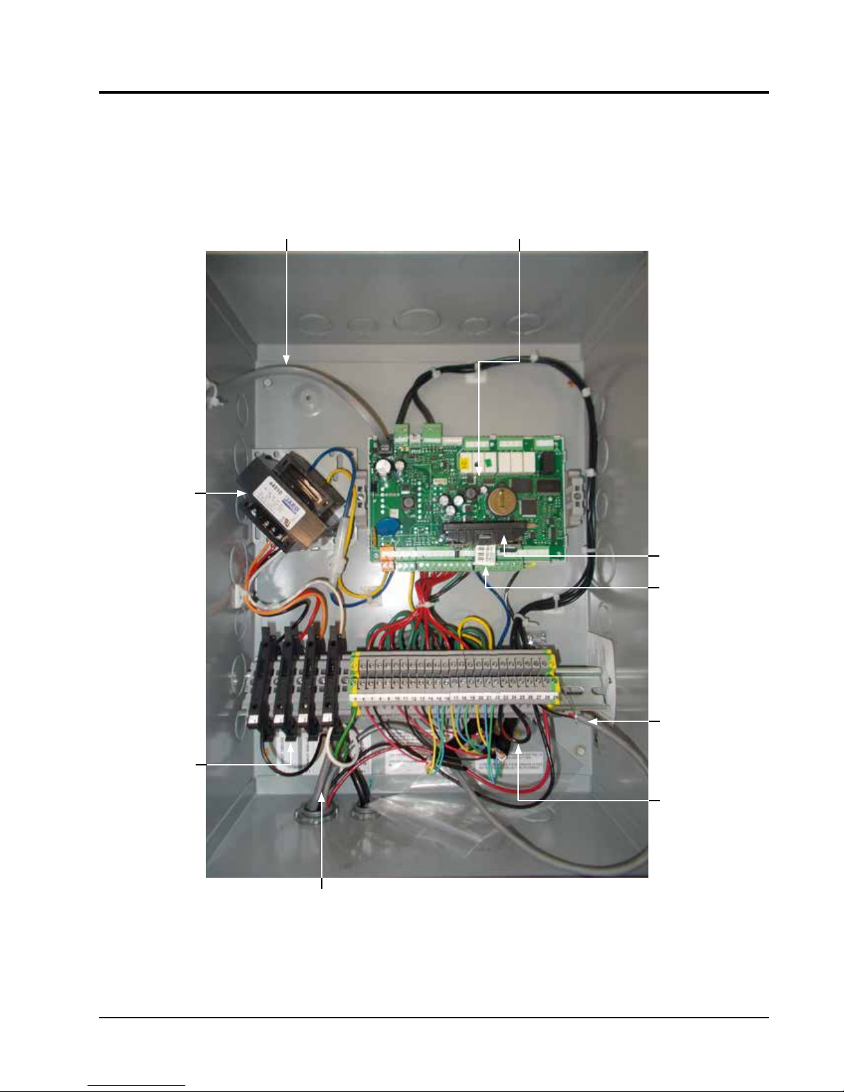
FIGURE 1.11
Typical LC5000 Wiring
RJ11 Cable
to Display
PLC Board
Transformer
Power Input
120V, 230V
& 240V
Web Card
Ethernet Cable
Connection
RS485
Communication
Cable
Smoke Alarm
Jumper
Zone 1, 2 & 3
Shielded Wires
Sensor
Manual 2100-642
Page 19 of 82
!
WARNING
Electrical shock hazard.
Disconnect VAC power supplies before
servicing.
Failure to do so could result in electric shock
or death.
LC5000-100 CONTROLLER
The Bard-LinkTM LC5000-100 controller is part of
the wall mount Free Cooling Unit system. It is used
to control up to 12 wall-mount air conditioners from
one controller. The microprocessor control provides an
easy-to-read interface with large LCD graphical display.
It provides total redundancy for the structure and
equal wear on both units. The Bard-LinkTM controller is
configured for lead/lag/lead/lag sequence.
Conduit is recommended for all wiring. Use separate
conduits for communication and supply wiring.
1. Mounting the Controller
TM
Because the Bard-Link
temperature sensor as opposed to one located in the
controller box, the controller itself can be installed in
any indoor location that is suitable, preferably at eye
level. Four (4) mounting holes are provided for mounting
to the wall and holes for conduit connections are provided
in both the base, sides and top of the controller.
controller utilizes a remote
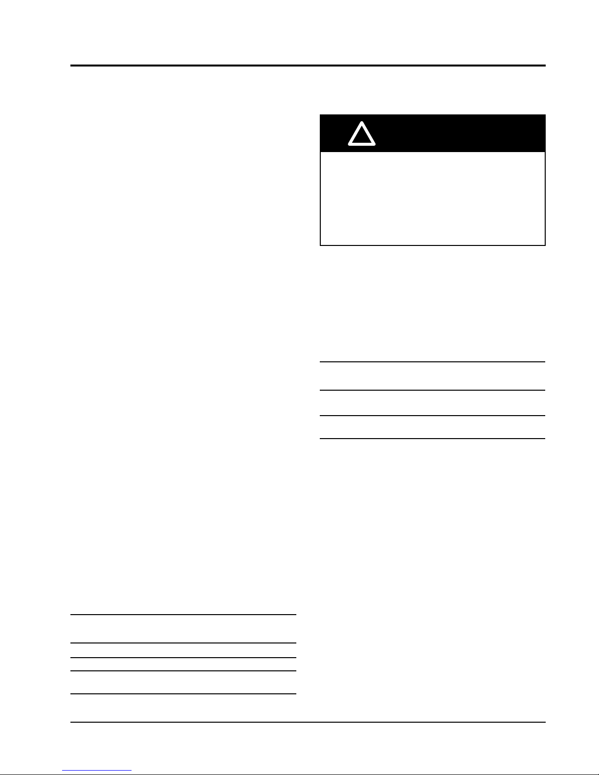
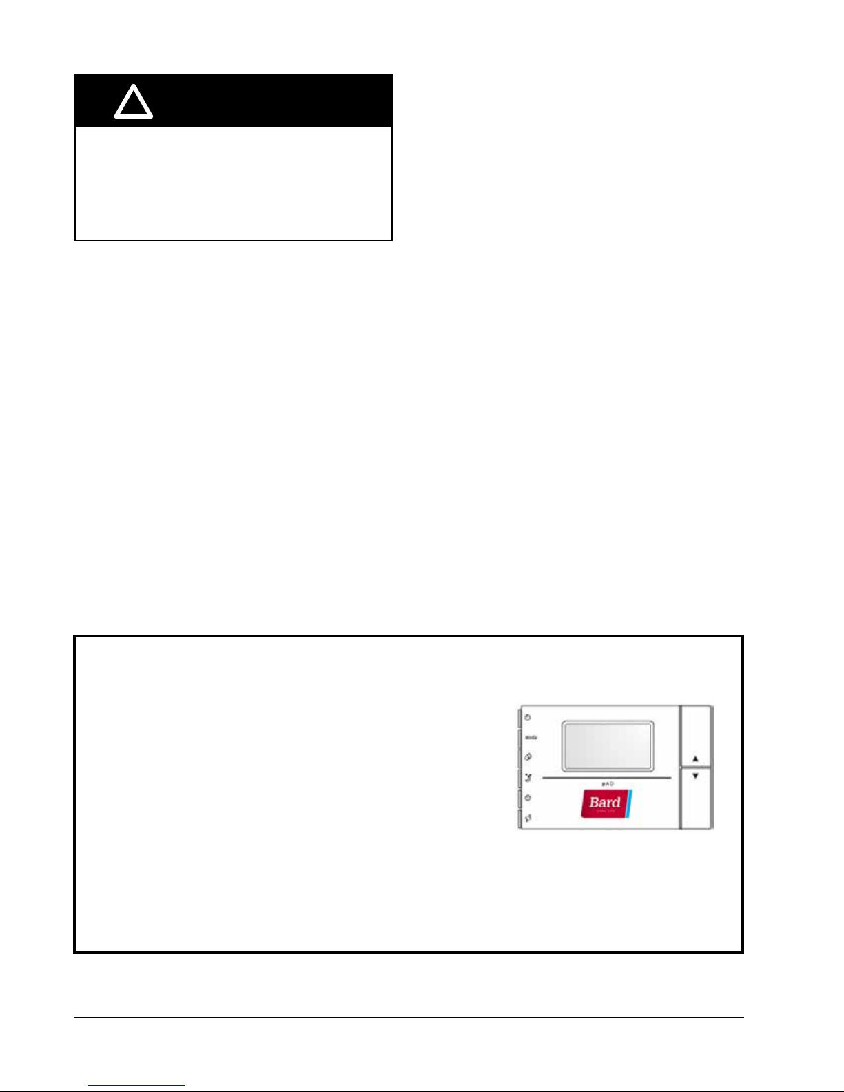
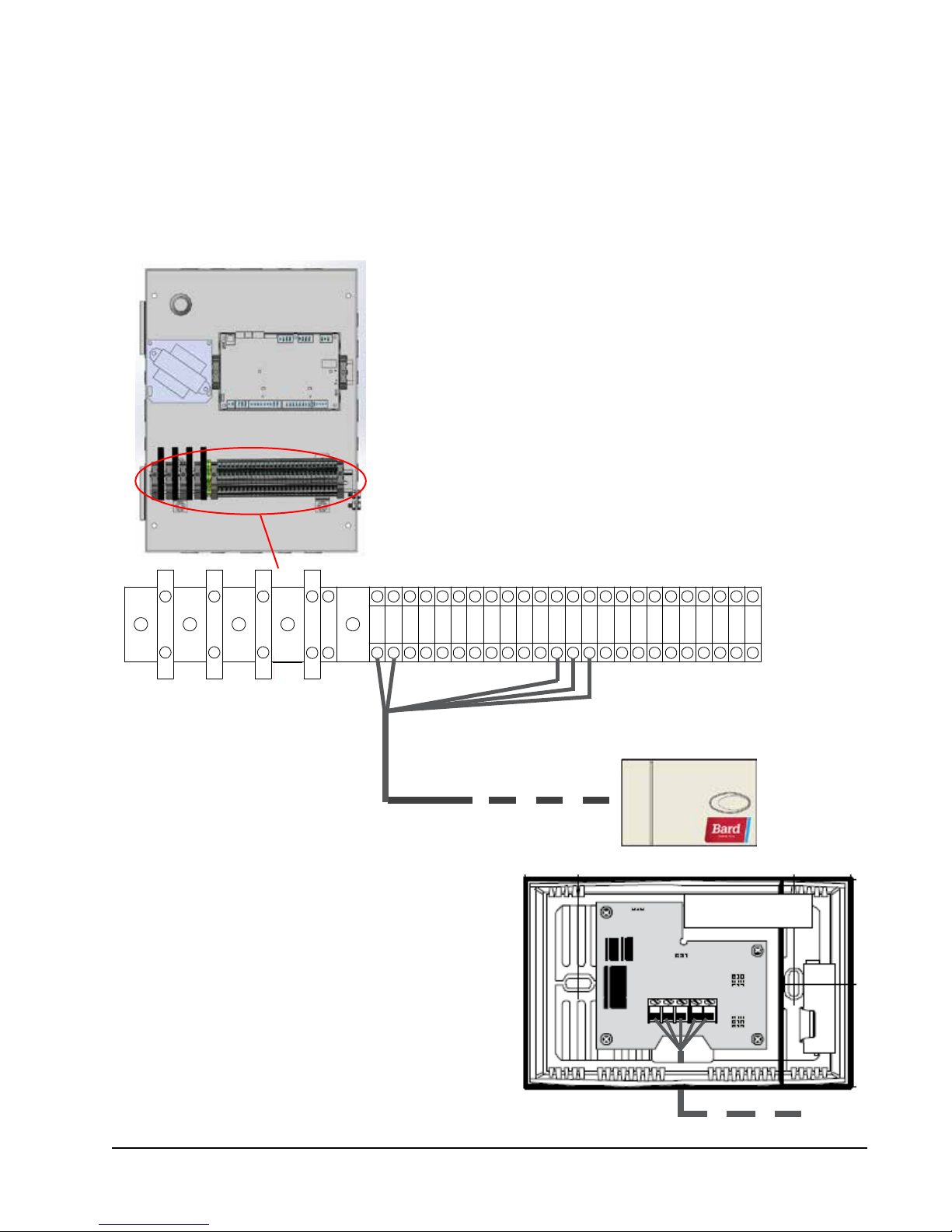
Single Unit Operation
Bard thermostat 8403-077 or 8403-078 can be used in place
of the BARD-LINK
mount air conditioner is being installed. If using a thermostat
instead of the PLC controller, the alarm logging and remote
communication capabilities of the controller will not be available.
8403-077 Single Unit Controller, backup real time clock, buzzer
and backlit display.
8403-078 Single Unit Controller, buzzer and backlit display.
For optimum temperature sensor performance, the thermostat
should be mounted on an interior wall and away from any heat
sources, sunlight, windows, air vents, air circulation obstructions
and/or any other cause of erratic or false temperature sensing.
Follow the instructions included with 8403-077 or 8403-078 for
wiring connections from the thermostat to the wall-mount unit.
Manual 2100-642
Page 20 of 82
TM
PLC controller when only one W-Series wall
2. Installing Remote Indoor Temperature/Humidity Sensor(s)
One remote indoor temperature/humidity sensor is included with the controller. This sensor must be installed for
proper operation. Use shielded cable to mount the temperature/humidity sensor in a location least likely to be affected
by open doors, rack-mounted fans, radiant heat sources, etc. Locating the sensor between both return grilles is often
the best location, but every installation is unique. Location height should be approximately 48" above the floor. The
sensor should be installed on a 4" by 4" junction box to allow for control wire conduit (see Figure 1.12).
FIGURE 1.12
Remote Indoor Temperature/Humidity Sensor Installation
1. Connect wires from the 18 gauge shielded cable to terminals
#6, #7, #17, #18 and #19.
2
1043
2. Connect the other end of the shielded cable to the sensor
terminals. Be sure wires are connected to proper terminals.
Sensor is best mounted on a junction box, and it is
recommended that the cable be in conduit.
291 6 789 11 12 13 14 15 16 17 18 19 20 21 22 23 24 255 26 27 28
Manual 2100-642
Page 21 of 82
For proper operation, the remote indoor temperature/humidity sensor must be configured properly with the
controller. If only the single remote indoor temperature/humidity sensor supplied with the controller is installed, the
configuration setting is "0". This is the default setting. An additional remote indoor temperature-only sensor can be
purchased and installed in Zone 1. Also, temperature and humidity sensors can also be purchased and installed
in Zones 2 and 3 (one per zone). For information on remote indoor sensor configuration, see section on additional
sensors beginning on page 46.
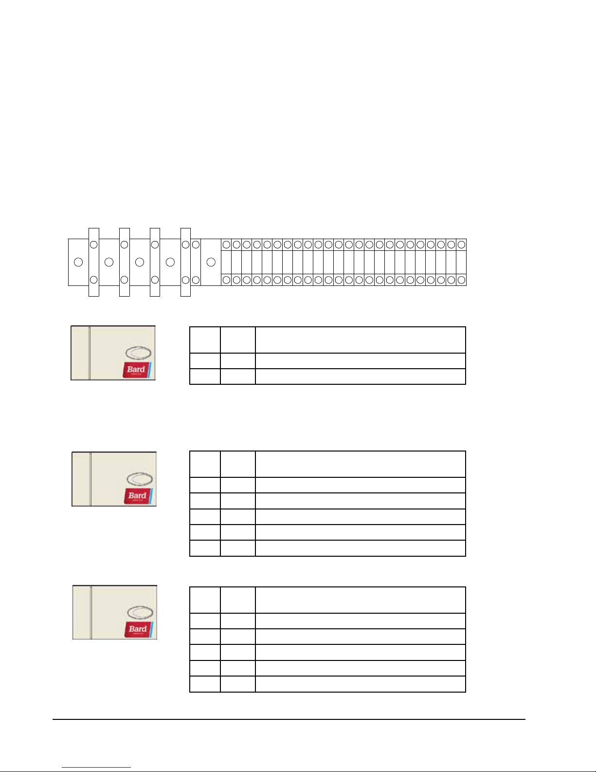
FIGURE 1.13
Additional Remote Temperature and Temperature/Humidity Sensor Installation
One additional temperature sensor can be added to Zone 1 and additional temperature/humidity sensors may be
added to Zones 2 and 3 (one per zone). Be sure the sensors are connected to the proper terminals as listed below.
2
Zone 1:
Optional Remote
Temperature Sensor
Terminals 8 & 9*
Zone 2:
Optional Remote
Temperature/Humidity Sensor
Terminals 10, 11, 20, 21 & 22
1043
TB#
Wire
Mark
Description
8 B2 Indoor Remote Sensor (Zone 1 – optional)
9 GND Ground
* The two wire connections for the optional remote temperature
sensor are not polarity sensitive.
TB#
Wire
Mark
Description
10 B3 Indoor Remote Sensor (Zone 2)
11 GND Ground
20 B7 Remote Indoor Humidity Sensor: 0-1 VDC (Zone 2)
21 GND Ground
22 +5V ref Power for B7
291 6 789 11 12 13 14 15 16 17 18 19 20 21 22 23 24 255 26 27 28
TB#
12 B4 Indoor Remote Sensor (Zone 3)
13 GND Ground
Zone 3:
Optional Remote
Temperature/Humidity Sensor
Terminals 12, 13, 14, 15 & 16
14 B5 Remote Indoor Humidity Sensor: 0-1 VDC (Zone 3)
15 GND Ground
16 +VDC Power for B5
Manual 2100-642
Page 22 of 82
Wire
Mark
Description
3. Smoke Alarm
The LC5000 PLC controller is shipped with smoke detector contacts. There is a factory-installed jumper across
terminals #23 and #24. If there is no smoke detector, no action is necessary. If smoke detector alarm is desired,
please remove the factory-installed jumper and wire per Figure 1.14.
FIGURE 1.14
Power and Signal Connections for Smoke Detector
See Terminal Block Index
on page 29
Manual 2100-642
Page 23 of 82
4. Communication Wiring
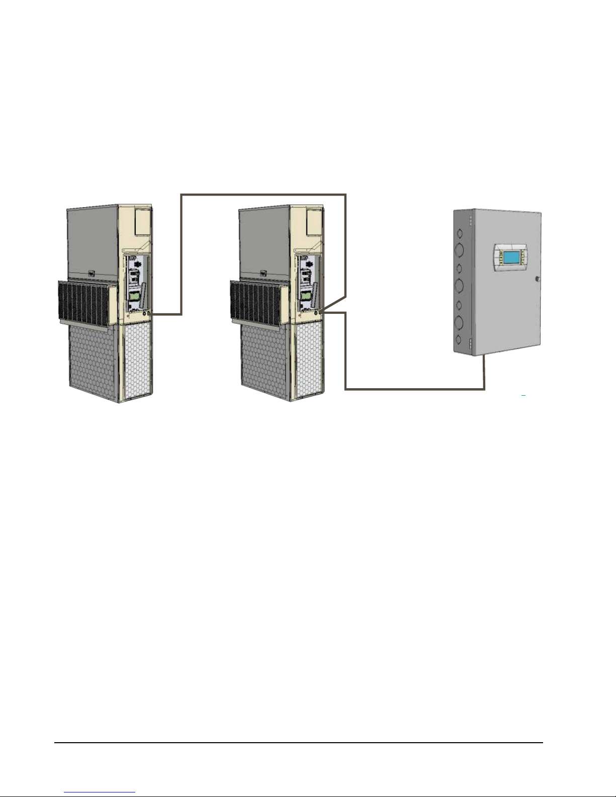
Connect the communication wiring from the wall-mount units to the controller in the manner shown in Figure 1.15.
The communication wire should be 2-wire, 18 gauge shielded cable with drain. Any color can be used. Be sure to
match "+" and "-" symbols on controller terminal blocks to prewired unit control terminal block (see Figures 1.17 and
1.18 on pages 26 and 27). Attach communication wire filters as shown in Figure 1.16. Use separate conduits for
communication and supply wiring.
FIGURE 1.15
Communication Wiring
Wall-Mount Unit Wall-Mount Unit
Bard-LinkTM
Controller
Manual 2100-642
Page 24 of 82
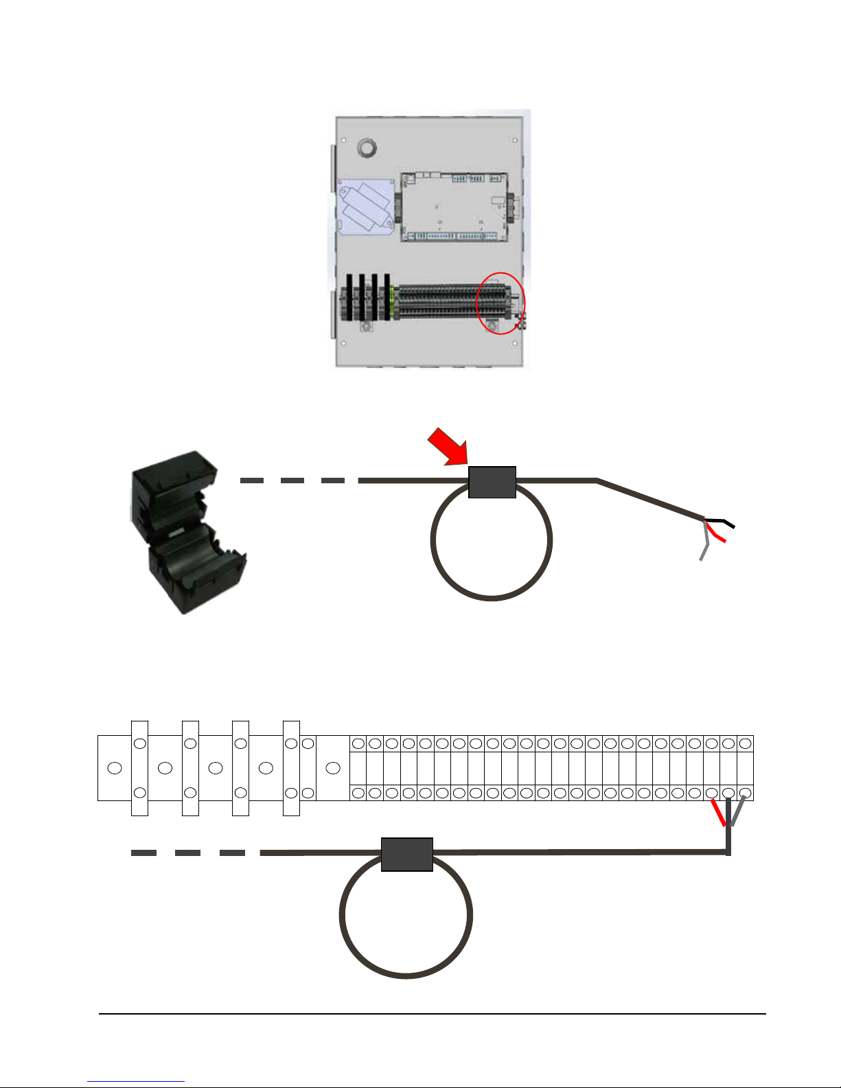
FIGURE 1.16
- +
G
1043
2
291 6 789 11 12 13 14 15 16 17 18 19 20 21 22 23 24 255 26 27 28
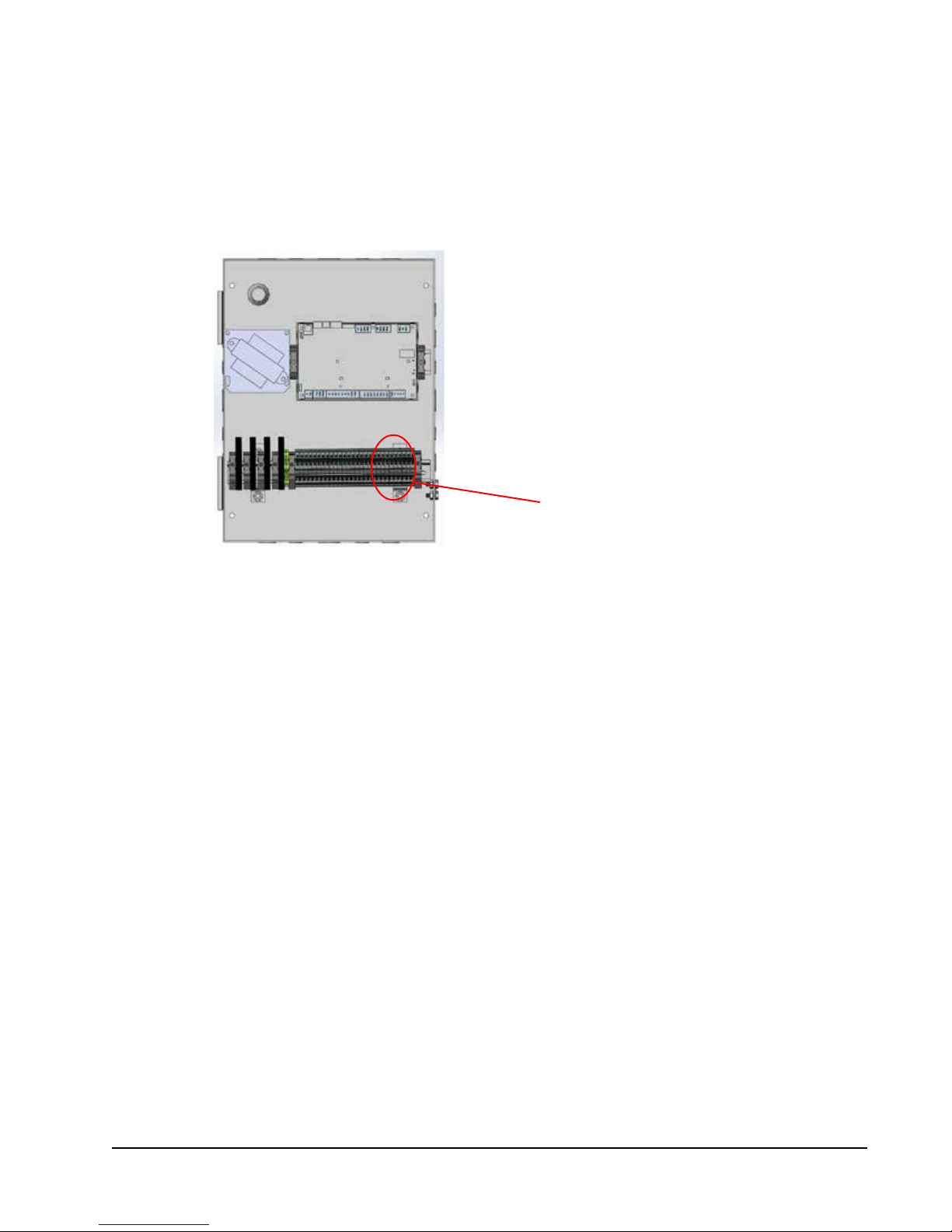
Communication Wiring: Termination at the Controller
1. Using the field-provided shielded cable, make a small service loop after entering the controller and attach the provided
EMI filter at the intersection of the loop.
2. Connect one wire to terminal #27 (negative), the other wire to terminal #28 (positive) and the drain wire to ground
terminal #29.
To Wall-Mount Unit 1
Control Board RS485
Manual 2100-642
Page 25 of 82
 Loading...