

QT
EC
Wall Sleeve
INSTALLATION
INSTRUCTIONS
Models
: QWS48A
QWS48A-16
QWS48A-19
QWS48A-23
QWS48A-30
© Copyright 2003
Bard Manufacturing Company
Bryan, Ohio 43506
Since 1914 . . . Moving ahead just as
planned.
Manual No.: 2100-319F
Supersedes: 21 10-319E
File: Vol. II Tab 14
Date: 11-07-05
Manual 2100-319F
Page 1 of 10

CONTENTS
Getting Other Information and Publications 3
EC Wall Sleeve General Information
QT
Shipping Damage .................................................. 4
General .................................................................. 4
Installation Instructions
Installation Wood Framed Walls......................4 & 6
Installation Masonry Construction Walls..........6 & 7
Accessory Item – QCDS48
Installation with 16" Thick Walls ............................ 8
Installation with 19" Thick Walls ............................ 8
Installation with 23" Thick Walls ............................ 8
Installation with 30" Thick Walls ............................ 8
Accessory Item - QCDS48
Condensate Disposal System................................ 9
Attachment of Wall Sleeve to Unit ....................... 10
Figures
Figure 1 Wood Framed Installation..................... 4
Figure 2 Application of Sealant to 2 x 6 Plate..... 5
Figure 3 Application of Sealant to Flanges ......... 5
Figure 4 Masonry Construction Installation......... 6
Figure 5 Typical Installation With 14"
Maximum Wall Thickness..................... 7
Figure 6 Condenser Fill Plate Application........... 8
Figure 7 QCDS48 Condensate Disposal
System.................................................. 9
Figure 8 Attaching Base Assembly to Sleeve
Showing Caulking ............................... 10
Manual 2100-319F
Page 2 of 10

Getting Other Information and Publications
These publications can help you install the air
conditioner or heat pump. You can usually find these at
your local library or purchase them directly from the
publisher. Be sure to consult current edition of each
standard.
Standard for the Installation of ...........ANSI/NFPA 90A
Air Conditioning and
Ventilating Systems
Standard for Warm Air Heating ......... ANSI/NFPA 90B
Air Conditioning Systems
QT
EC
Installation Instruction Manual..... Bard/2100-288
FOR MORE INFORMATION, CONTACT THESE
PUBLISHERS:
ACCA Air Conditioning Contractors of America
1712 New Hampshire Avenue, NW
Washington, DC 20009
Telephone: (202) 483-9370
Fax: (202) 234-4721
ANSI American National Standards Institute
11 West Street, 13th Floor
New York, NY 10036
Telephone: (212) 642-4900
Fax: (212) 302-1286
ASHRAE American Society of Heating, Refrigerating
& Air Conditioning Engineers, Inc.
1791 Tullie Circle, N.E.
Atlanta, GA 30329-2305
Telephone: (404) 636-8400
Fax: (404) 321-5478
BARD Bard Manufacturing Company
1914 Randolph Drive
Bryan, OH 43506
Telephone: (419) 636-1194
Fax: (419) 636-2640
Manual 2100-319F
Page 3 of 10

SHIPPING DAMAGE
Upon receipt of equipment, the carton should be checked
for external signs of shipping damage. If damage is
found, the receiving party must contact the last carrier
immediately, preferably in writing requesting inspection
by the carrier’s agent.
GENERAL
The QWS48A series is designed for use with the QT
Series Air Conditioners and Air Source Heat Pumps.
The QWS48A is for use with wall thickness of 5 to 14
inches. One QWS48A series wall sleeve is required for
each QTEC Model to be installed.
The equipment covered in this manual is to be installed
by trained service and installation technicians.
These instructions explain the recommended method to
install the wall sleeve.
These instructions and any instructions packaged with
any separate equipment required to make the entire air
conditioning system should be carefully read before
beginning the installation.
While these instructions are intended as a general
recommended guide, they do not supersede any national
and/or local codes in any way. Authorities having
jurisdiction should be consulted before the installation is
made.
FIGURE 1
WOOD FRAMED INSTALLATION
EC
INSTALLATION – WOOD FRAMED
WALLS
For wood frame construction walls, the dimensions of
the opening must be 48 inches tall by 43 inches wide. A
2 x 6 header will be required for the opening. The sides
of the opening must have trimmer studs to support the
header, and to provide a structural member on which to
fasten the sleeve. (See Figure 1.) All of the dimensions
are referenced from the finished floor height.
After the opening is framed in, a treated 2 x 6 bottom
support and seal plate must be cut to fit in the bottom of
the opening. Construction adhesive should be applied to
the 2 x 6 before it is put in place. (See Figure 2.) This
will help hold the plate in place and provide an
additional seal for the bottom of the opening. The
treated 2 x 6 must be fastened to the bottom of the
opening flush to the finished surface of the outside wall.
The 2 x 6 must be sealed to the outside wall with
construction adhesive. Any gaps between the sides of
the 2 x 6 plate and the opening must also be sealed. See
Figure 2. NOTE: The actual thickness of 2 x 6 must be
1-1/2".
Once the opening is framed, the sheeting can be
installed, the sheeting material must not extend into the
opening.
The sleeve should be test fit into the opening to make
sure of the dimensions. The sleeve must be inserted into
the opening from the outside of the building. The
bottom of the sleeve must be level from side to side, and
the sleeve must be square in the opening. A slope is
built into the bottom of the sleeve from the inside to the
outside. This will allow any water that gets into the
sleeve to drain out. Once the test fit is completed, the
sleeve must be removed from the opening, and two 1/4
inch beads of sealant must be applied to the mounting
flanges of the sleeve. (See Figure 3.)
Manual 2100-319F
Page 4 of 10

FIGURE 2
APPLICATION OF SEALANT TO 2 X 6 PLATE
APPLY CONSTRUCTION
ADHESIVE TO SEAL.
APPLY CONSTRUCTION ADHESIVE TO SEAL.
SLEEVE OPENING
TREATED 2 X 6 BOTT OM SUPPORT AND SEAL PLA TE
FRONT VIEW
FIGURE 3
APPLICATION OF SEALANT TO FLANGES
OUTSIDE
WALL
APPLY CONSTRUCTION
ADHESIVE TO SEAL.
Manual 2100-319F
Page 5 of 10
The sleeve is then reinserted into the prepared opening
from the outside of the building. All of the mounting
flanges must contact the exterior wall. Check to see
that there is enough sealant to make this joint
watertight. Additional sealant must be applied as
necessary. The sleeve must be centered in the opening,
and the bottom of the sleeve must be checked to make
certain that it is level from side to side. The bottom
flange should be secured to the wall by using two
screws through the holes in the bottom mounting flange
of the sleeve. The sleeve must be checked to make sure
that it is square in the opening. Once the sleeve is
square, the side and top mounting flanges of the sleeve
must be secured to the wall with screws through the
holes in the flanges. The gaps between the side flanges,
and the top and bottom flanges must be filled with
additional sealant.
On the inside of the building, the gaps between the
sleeve and the opening must be filled with insulation.
This will help insulate the sleeve and prevent any
unwanted outdoor air. See Figure 5.
If the QT
EC
unit will be drained through the wall, the
drain line must be installed through the wall.
Information for the drain installation is contained in the
QTEC Installation Instructions.
INSTALLATION – MASONRY
CONSTRUCTION WALLS
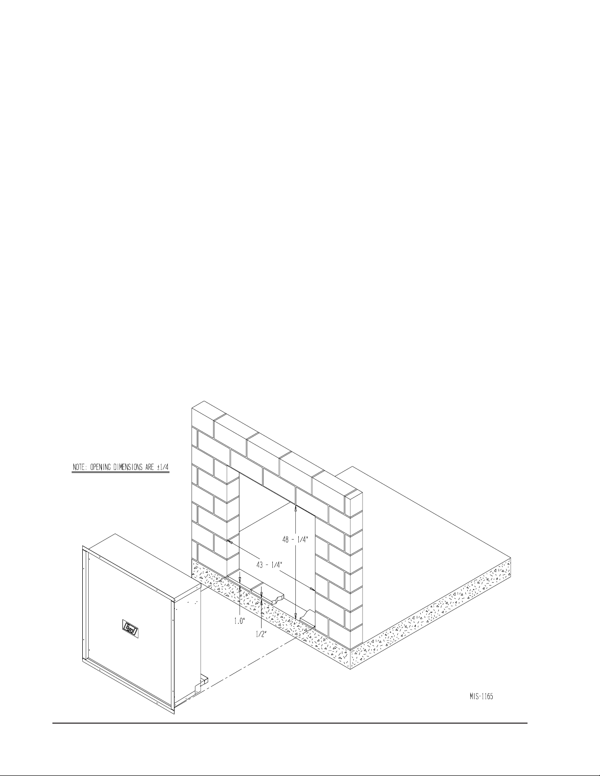
For masonry construction walls, the dimensions for the
opening will be 48-1/4 inches tall by 43-1/4 inches wide.
These dimensions are plus or minus 1/4 inch and are
measured from the finished floor height. See Figure 4.
These will be the finish dimensions of the opening.
A 1-1/2 inch spacer needs to be installed in the bottom
of the opening to raise the sleeve off the floor. Masonry
blocks 1 inch thick, minimum of 6 inches wide, with 1/2
inch mortar between the block and floor will provide the
required spacing. These blocks are to be laid flush with
the outside wall, and must provide a water tight seal to
the floor and to the opening sides. See Figure 2.
The sleeve should be test fit in the opening before final
preparations are made. The sleeve will be installed into
the opening from the outside of the building in. The
sleeve must be centered in the opening from side to side.
The mounting flanges of the sleeve must contact the
outside wall all around the opening. The side and top
mounting flanges must have the mounting holes drilled
into the outside wall for the concrete anchors which will
hold the sleeve in the wall. The holes should be drilled
through the holes in the sleeve with the sleeve level and
FIGURE 4
MASONRY CONSTRUCTION INSTALLATION
Manual 2100-319F
Page 6 of 10

square in the opening. A slope is built into the bottom of
the sleeve from the inside to the outside. This will allow
any water that gets into the sleeve to drain out. Once the
test fitting has been checked out, the sleeve should be
removed from the wall.
sealant must be applied as required. The sleeve must be
anchored to the wall. All four mounting flanges must be
fastened with two fasteners each to the outside wall.
The gaps between the side flanges, and the top and
bottom flanges must be sealed to the wall.
With the sleeve removed, two 1/4 inch beads of sealant
must be applied to the flanges that contact the outside
wall. See Figure 3
The sleeve must be installed back in the wall making
sure that the predrilled holes in the wall line up with the
holes in the mounting flanges of the sleeve. Check to
make sure that there is enough sealant between the wall
and the flanges to make the joint watertight. Additional
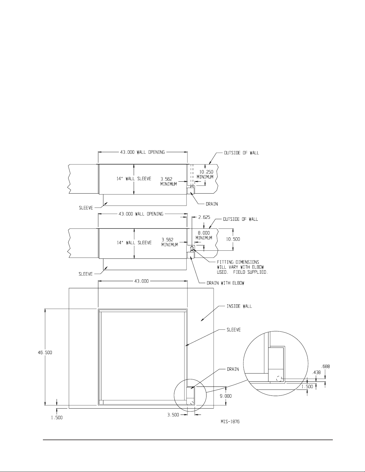
TYPICAL INSTALLATION WITH 14" MAX. WALL THICKNESS
INSIDE
WALL
WALL BRACKET
On the inside of the building, the gaps between the
sleeve and the opening must be filled with insulation.
This will help insulate the sleeve and prevent infiltration
of any unwanted outdoor air. See Figure 5.
If the QTEC unit will be drained through the wall, the
drain line must be installed through the wall.
Information for the drain installation is contained in the
QTEC Installation Instructions.
FIGURE 5
OUTSIDE WALL
INSULATION
OUTDOOR GRILLE
QTEC UNIT
WALL BRACKET
CONDENSER COIL AND F AN
INSERTED INTO SLEEVE
INSULATION
TOP SECTION VIEW
Manual 2100-319F
Page 7 of 10

INSTALLATION WITH 16" THICK WALLS
When an application is required on a building with 16" wall,
a Wall Sleeve model number QWS48A-16 is required.
INSTALLATION WITH 23" THICK WALLS
When an application is required on a building with 23" wall,
a Wall Sleeve model number QWS48A-23 is required.
The installation of the QWS48A-16 is similar to the
QWS48A with one exception. A condenser fill plate is
supplied with QWS48A-16, and is to be attached to the top
of the outdoor coil housing on the QT
EC
unit. See Figure 6.
To attach fill plate, remove the three screws on top of coil
section, place condenser fill plate and secure with the three
screws.
INSTALLATION WITH 19" THICK WALLS
When an application is required on a building with 19" wall,
a Wall Sleeve model number QWS48A-19 is required.
The installation of the QWS48A-19 is similar to the
QWS48A with one exception. A condenser fill plate is
supplied with QWS48A-19, and is to be attached to the top
EC
of the outdoor coil housing on the QT
To attach fill plate, remove the three screws on top of coil
section, place condenser fill plate and secure with the three
screws.
unit. See Figure 6.
The installation of the QWS48A-23 is similar to the
QWS48A with one exception. A condenser fill plate is
supplied with QWS48A-23, and is to be attached to the top
EC
of the outdoor coil housing on the QT
unit. See Figure 6.
To attach fill plate, remove the three screws on top of coil
section, place condenser fill plate and secure with the three
screws.
INSTALLATION WITH 30" THICK WALLS
When an application is required on a building with 30" wall,
a Wall Sleeve model number QWS48A-30 is required.
The installation of the QWS48A-30 is similar to the
QWS48A with one exception. A condenser fill plate is
supplied with QWS48A-30, and is to be attached to the top
EC
of the outdoor coil housing on the QT
To attach fill plate, remove the three screws on top of coil
section, place condenser fill plate and secure with the three
screws.
unit. See Figure 6.
FIGURE 6
INSTALLATION OF CONDENSER FILL PLATE IN QWS48A-16, QWS48A-19, QWS48-23, QWS48-30 APPLICATION
CONDENSER
FILL PLA TE
SCREW
CONDENSER
FILL PLA TE
SEAL
Manual 2100-319F
Page 8 of 10
ACCESSORY ITEM
The QCDS48 is a condensate disposal system for use on
all QTEC models. The system consists of a drain box
and a rear drain assembly. The drain attaches to the side
of the sleeve. The drain box has a rear drain and an
overflow. The rear drain assembly installs in the rear
QCDS48 CONDENSATE DISPOSAL SYSTEM
drain of the QTEC. This system allows the QTEC unit to
be installed or removed from the sleeve without
connecting or disconnecting the drain line.
The installation of the QCDS48 requires that a recessed
area next to the sleeve opening be built. See Figure 7 for
dimensions of the recess for the drain box.
FIGURE 7
Manual 2100-319F
Page 9 of 10

ATTACHMENT OF WALL SLEEVE TO
EC
UNIT
QT
All Wall Sleeve Models covered in this manual are
equipped with two different methods to attach the QT
Model being applied.
The first method is with brackets supplied with the QT
unit. These brackets are screwed to the sleeve side with
six screws per side. This method can be used if adequate
clearance is available on each side of the unit to drive
the screws. If this method is used, the studs attached to
the wall sleeve must me removed and discarded.
The second method is for installation where there is not
adequate clearance to drive the screws into the cabinet
sides. The attachment can be made from inside the unit.
There are two threaded studs extending from the room
side of the sleeve to matching holes in the unit rear
panel, and are secured with a 5/16" nut on each side.
See Figure 3.
FIGURE 8
ATTACHING BASE ASSEMBLY TO SLEEVE
SHOWING CAULKING
EC
EC
To use this method, discard the two side mounting
brackets. Remove the nuts and washers from the
threaded studs and retain for use later. Remove the
lower cabinet door and locate the mating holes in the
rear of the cabinet. It may be necessary to clear the
holes of gasket material.
Roll unit into place making sure the unit is aligned from
side to side and that studs have entered the holes in the
cabinet back. Push unit back until the rubber seal on the
rear of the cabinet touches the flange on the wall sleeve.
Replace the washers and nuts previously removed from
the studs. Tighten nuts until there is some compression
of the gasket. Replace the lower cabinet panel.
Manual 2100-319F
Page 10 of 10
ATTATCH BASE
ASSEMBLY TO SLEEVE
SEAL BETWEEN SLEEVE &
BRACKET WITH SEALANT
AS SHOWN
SEAL CORNER OF
BRACKET WITH SEALANT
AS SHOWN
MIS-1848
 Loading...