

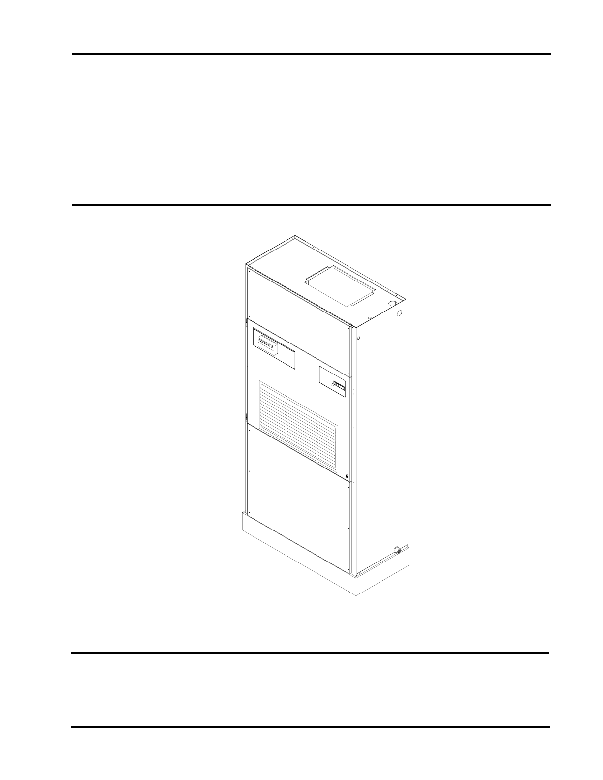
QC SERIES
INSTALLATION
INSTRUCTIONS
CHILLED WATER UNIT
Model:
QC501
Bard Manufacturing Company
Bryan, Ohio 43506
Since 1914...Moving ahead, just as planned.
MIS-1554
Manual No.: 2100-416C
Supersedes: 2100416B
File: Vol II Tab 14
Date: 12-22-03
© Copyright 2003

CONTENTS
Getting Other Information and Publications
For more information, contact these publishers: ..... 1
QC General Information
QC Model Nomenclature ......................................... 2
Shipping Damage .................................................... 5
Unit Removal From Skid.......................................... 5
Handling Unit After Removal From Skid .................. 5
Removal of Wall Bracket from Shipping Location ... 6
General.................................................................... 6
Minimum Installation Height .................................... 6
Duct Work................................................................ 9
Filters....................................................................... 9
Condensate Drain.................................................. 10
Mist Eleminator Service ..........................................11
Figures
Figure 1 Unit Dimensions..................................... 4
Figure 2 Removal of Unit From Skid .................... 5
Figure 3 Proper Handling of Unit After Removal
from Skid................................................ 6
Figure 4 Installation of Unit w/Wall Sleeve .......... 7
Figure 5 Installation With Free Blow Plenum....... 8
Figure 6 Ducted Application................................. 8
Figure 7 Supply Duct Connections ...................... 9
Figure 8 Filter Location ........................................ 9
Figure 9A Side Drain (Side View)......................... 10
Figure 9B Optional Rear Drain ............................. 10
Figure 9C Rear Drain (Top View).......................... 10
Figure 10 Fresh Air Damper Removal ................. 12
Figure 11 Removal of QT
Figure 12 Remove Locking Screws from Wheels 14
Figure 13 Unit Mounting Without Wall Sleeve ..... 15
Figure 14 Component Location............................ 16
Figure 15 Low Voltage Wire Harness Plug .......... 18
Figure 16 Remote Thermostat Wiring "X" Option 19
Figure 17 Remote Thermostat Wiring "D" Option 20
Figure 18 Internal 2-Way Valve Piping................. 24
Figure 19 Internal 3-Way Valve Piping................. 25
EC ERV......................... 13
Installation Instructions
Mounting the Unit .................................................. 14
Wiring – Main Power ............................................. 17
Wiring – Low Voltage Wiring ................................. 17
General Information ............................................... 17
Fluid Connections.................................................. 17
Low Voltage Connections...................................... 18
Start Up
Optional CFM ........................................................ 21
Important Installer Note ......................................... 21
Service Hints ......................................................... 21
Sequence of Operation.......................................... 21
Troubleshooting ECM Blower Motors ............. 22-23
Tables
Table 1 Factory Built-In Electric Heat ................... 2
Table 2 Electrical Specifications ........................... 2
Table 2A Cooling Performance Chart...................... 3
Table 3 Operating Voltage Range....................... 17
Table 4 Wall Thermostats and Subbase
Combinations ......................................... 17
Table 5 Indoor Blower Performance ................... 21
i

GETTING OTHER INFORMATION AND PUBLICATIONS
These publications can help you install the air
conditioner or heat pump. You can usually find these at
your local library or purchase them directly from the
publisher. Be sure to consult current edition of each
standard.
National Electrical Code ......................ANSI/NFPA 70
Standard for the Installation ..............ANSI/NFPA 90A
of Air Conditioning and
Ventilating Systems
Standard for Warm Air...................... ANSI/NFPA 90B
Heating and Air
Conditioning Systems
Load Calculation for Residential ...... ACCA Manual J
Winter and Summer
Air Conditioning
Duct Design for Residential ............. ACCA Manual D
Winter and Summer Air Conditioning
and Equipment Selection
Closed-Loop/Ground Source Heat Pump........ IGSHPA
Systems Installation Guide
Grouting Procedures for Ground-Source ........ IGSHPA
Heat Pump Systems
Soil and Rock Classification for the Design ...IGSHPA
of Ground-Coupled Heat Pump Systems
Ground Source Installation Standards.............IGSHPA
Closed-Loop Geothermal Systems – Slinky ... IGSHPA
Installation Guide
FOR MORE INFORMATION, CONTACT
THESE PUBLISHERS:
ACCA Air Conditioning Contractors of America
1712 New Hampshire Avenue
Washington, DC 20009
Telephone: (202) 483-9370
Fax: (202) 234-4721
ANSI American National Standards Institute
11 West Street, 13th Floor
New York, NY 10036
Telephone: (212) 642-4900
Fax: (212) 302-1286
ASHRAE American Society of Heating Refrigerating,
and Air Conditioning Engineers, Inc.
1791 Tullie Circle, N.E.
Atlanta, GA 30329-2305
Telephone: (404) 636-8400
Fax: (404) 321-5478
NFPA National Fire Protection Association
Batterymarch Park
P.O. Box 9101
Quincy, MA 02269-9901
Telephone: (800) 344-3555
Fax: (617) 984-7057
IGSHPA International Ground Source
Heat Pump Association
490 Cordell South
Stillwater, OK 74078-8018
Manual 2100-416
Page 1
QC SERIES WATER SOURCE GENERAL INFORMATION
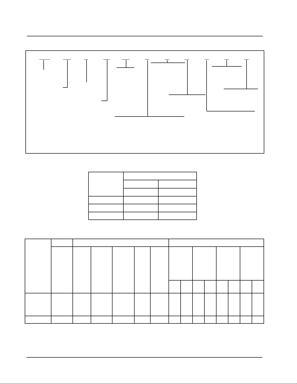
QC MODEL NOMENCLATURE
QC 50 1 – A 10 X X X X X X
Model Number
QC - QTec™ Model
Capacity
50 - 4 ton
NOTE 1: Electric heat available
for -A models only
Revision
Volts & Phase
A - 230/208-60-1
K - 115-60-1
FACTORY BUILT-IN ELECTRIC HEAT TABLE
Filter Options
KW
0Z - 0KW
05 - 5 KW
10 - 10KW
15 - 15KW
(Note 1)
Ventilation Option
B - Blank Off Plate (no ventilation)
X - Barometric Fresh Air Damper (no exhaust)
V - Commercial Ventilator (w/Exhaust)
P - Commercial Ventilator (w/Exhaust)
Motorized, Power Return
R - Energy Recovery Ventilator (w/Exhaust) - 230/208-60-1 versions only
X - 1 Inch Fiberglass
(Standard)
F - 2 Inch Fiberglass
P - 2 Inch pleated
Color
V - Platinum w/Slate
Front (vinyl)
4 - Gray Paint
TABLE 1
Valve Options
4 - 2-way valve
5 - 3-way valve
Internal Controls
X - None
Climate Control
X - None
D - Electronic/prog/man/auto
sledoMA-105CQ
1-V0421-V802
WKHUTBHUTB
0.5083,61092,21
0.01076,23075,42
0.51051,94068,63
TABLE 2
ELECTRICAL SPECIFICATIONS
tiucriCelgniStiucriClauD
3
.oN
detaR
&stloV
sledoM
Z0A-105CQ
50A01A51A-
Z0K-105CQ1-511101514141 ––––––––
sesahP
1-802/032
dleiF
rewoP
stiucriC
1
1
1
2ro1
muminiM
tiucriC
7
33
85
38
1
yticapmA
51
53
06
09
2
mumixaM
lanretxE
roesuF
tiucriC
rekaerB
41
8
6
4
2
dleiF
rewoP
eriW
eziS
eriW
eziS
41
01
01
8
3
muminiM
tiucriC
dnuorG
yticapmA
TKC
A
B
–
–
–
–
–
–
33
05
1
mumixaM
lanretxE
roesuF
tiucriC
rekaerB
TKC
TKC
A
B
–
–
–
–
–
–
04
05
2
dleiF
rewoP
eziSeriW
TKC
TKC
A
B
–
–
–
–
–
–
8
8
2
TKC
TKC
A
–
–
–
01
dnuorG
eziSeriW
TKC
B
–
–
–
01
Q
R
S
Manual 2100-416
Page 2
Maximum size of the time delay fuse or HACR type circuit breaker for protection of field wiring conductors.
Based on 75° C copper wire. All wiring must conform to the National Electrical Code and all local codes.
These “Minimum Circuit Ampacity” values are to be used for sizing the field power conductors. Refer to the National
Electric Code (latest revision), article 310 for power conductor sizing. CAUTION: When more than one field
power conductor circuit is run through one conduit, the conductors must be derated. Pay special attention to Note 8
of Table 310 regarding Ampacity Adjustment Factors when more than three conductors are in a raceway.
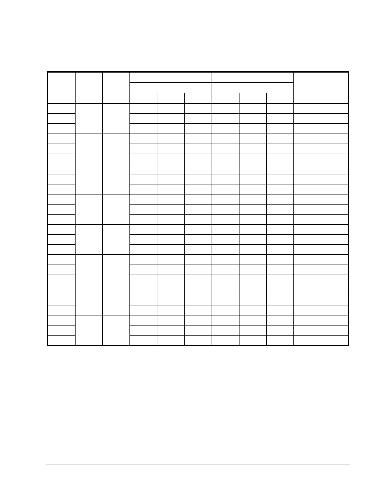
TABLE 2A
COOLING PERFORMANCE CHART
)0001(yticapaCHUTB)0001(yticapaCHUTB
MPGTWEMFC
6
84.611.113.55.148.627.413.35.7
014.717.117.52.344.728.519.43.11
6
81.516.015.44.834.520.313.35.7
010.611.119.40.040.620.419.43.11
6
89.311.018.33.530.423.113.35.7
017.416.011.49.636.423.219.43.11
6
86.216.90.32.236.226.93.35.7
016.640.013.37.332.325.019.43.11
6
84.712.212.50.646.034.513.35.7
018.818.210.63.949.134.719.43.11
6
82.617.115.47.242.925.313.35.7
014.713.211.56.544.032.519.43.11
6
89.413.116.35.939.726.113.35.7
011.617.111.10.240.920.319.43.11
6
87.318.019.22.635.627.93.35.7
017.412.115.33.835.728.019.43.11
240001
440001
640001
840001
240021
440021
640021
840021
latoTelbisneStnetaLlatoTelbisneStnetaLGISP.dH.tF
1.515.016.45.833.522.319.14.4
9.310.019.38.532.426.119.14.4
8.216.92.30.330.320.019.14.4
6.111.95.23.039.124.89.14.4
9.515.114.41.240.921.319.14.4
8.411.117.33.937.726.119.14.4
6.317.019.24.635.629.99.14.4
5.213.012.26.332.524.89.14.4
lioCretaW
porDerusserP1egatS2dna1egatS
Manual 2100-416
Page 3
Manual 2100-416
Page 4
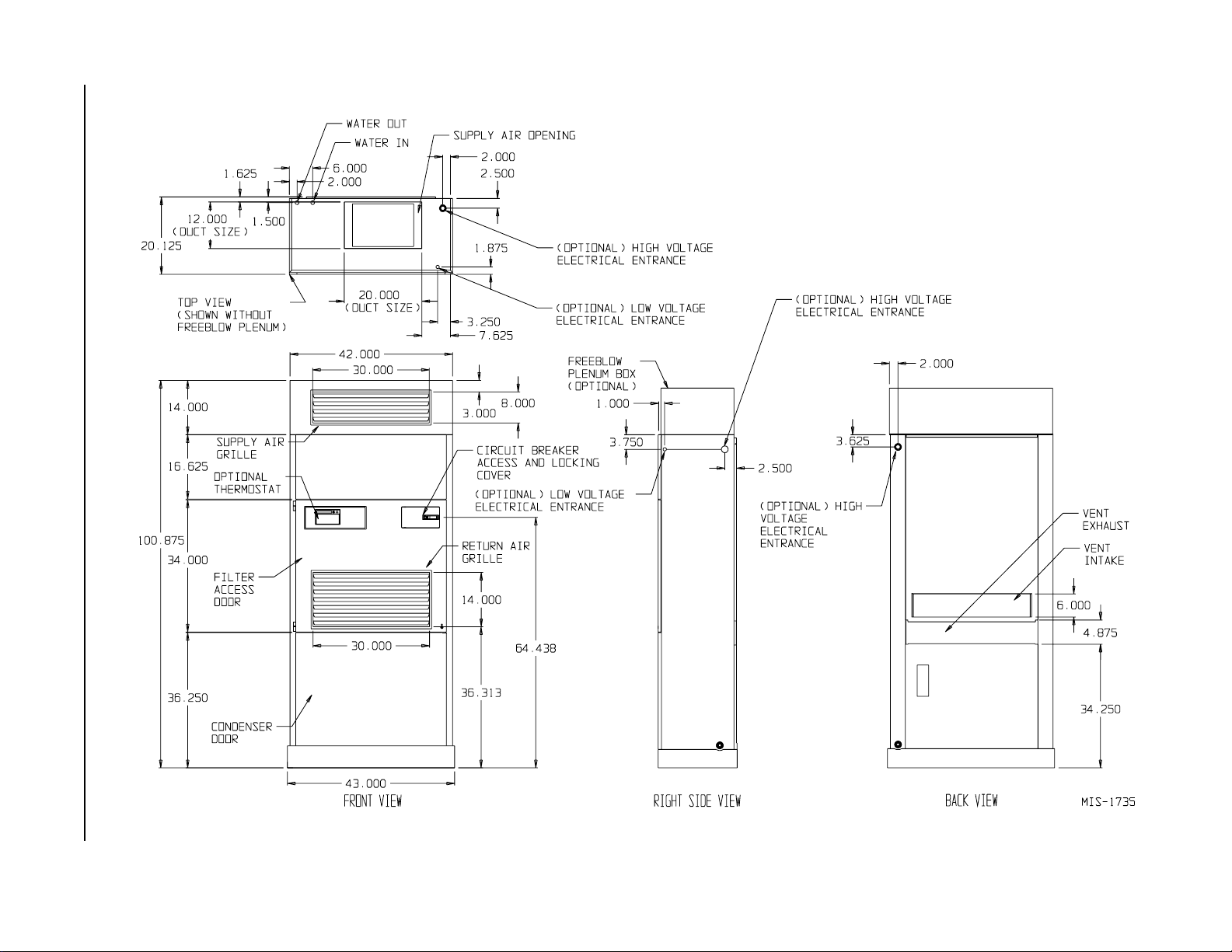
FIGURE 1
UNIT DIMENSIONS
SHIPPING DAMAGE
Upon receipt of equipment, the carton should be
checked for external signs of shipping damage. The
skid must remain attached to the unit until the unit is
ready for installation. If damage is found, the receiving
party must contact the last carrier immediately,
preferably in writing, requesting inspection by the
carrier’s agent.
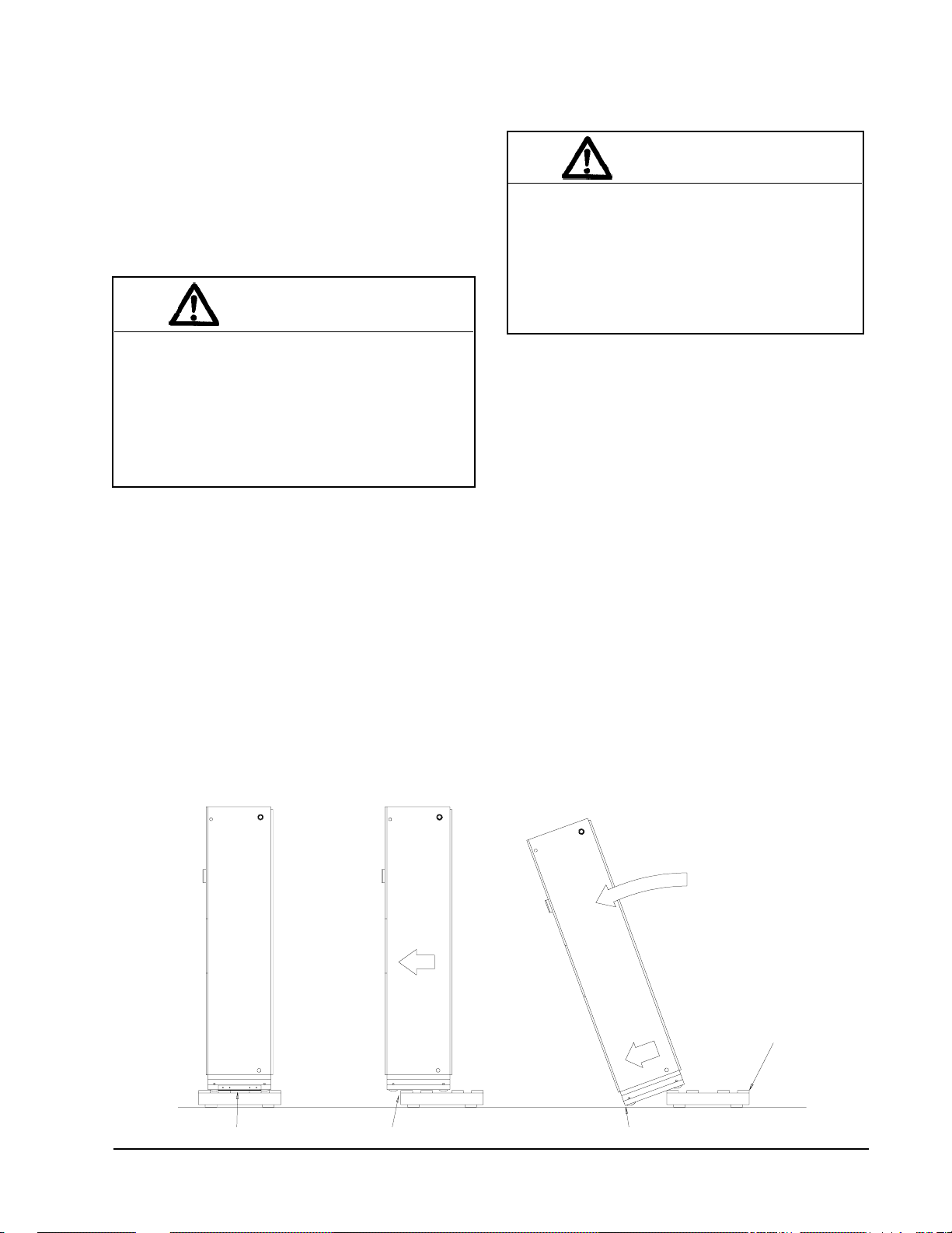
UNIT REMOVAL FROM SKID
WARNING
HANDLING UNIT AFTER REMOVAL FROM
SKID
W ARNING
Exercise extreme caution when pushing the
unit on the rollers. Handle and push from the
lower 1/3 of the unit. Insure that debris is not
on the floor where the unit is to be moved on
the rollers. Failure to do so could result in the
unit tipping over and causing bodily injury
and/or damage to the unit.
This unit is heavy and requires more than one
person to handle and remove from the skid.
Check unit wheels to ensure that wheels are
locked before removing from skid. Extreme
caution must be taken to prevent injury to
personnel and damage to the unit.
It is recommended that the unit not be removed from
the skid with a fork lift.
The shipping brackets on each side of the unit must be
removed and discarded. See Figure 2-A on Page 5.
The return air grille panel can be removed to provide a
place to hold the unit. The unit can be slid forward on
the skid until the front wheels hang over the edge of the
skid. See Figure 2-B. The unit can be tipped forward
and slid down the edge of the skid until the front
wheels touch the ground. See Figure 2-C. The wheels
will not roll. They are shipped from the factory locked
so they will not roll. The back of the skid will have to
be held down to keep it from tipping up. The skid can
be slid out from under the unit. The unit can then be
set upright.
REMOVAL OF UNIT FROM SKID
The unit will have to be turned sideways and removed
from the skid to fit through a 36” doorway. If the door
height allows, the unit can be slid sideways through the
door.
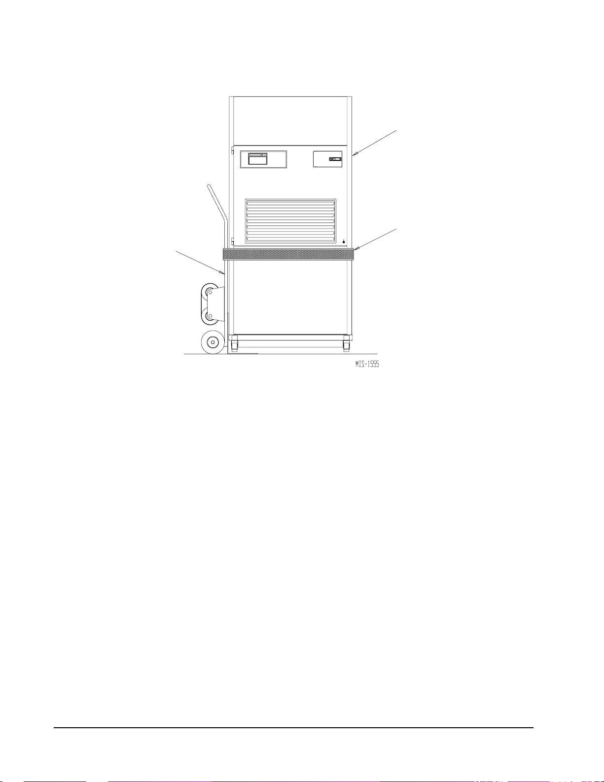
If the unit can not be slid through the door, then the unit
will have to be put on a cart and tipped down to roll
through the door. It is recommended that an appliance
cart by used with a strap to hold the unit on the cart.
The wheels of the unit must be locked. If the wheels
were allowed to roll, the unit could roll off the cart.
The blade of the appliance cart should be slid under the
wheels of the unit. See Figure 3. The strap of the
appliance cart should be placed around the unit and
strapped tightly. Help will be required to tip the unit
back onto the cart. The unit can be leaned far enough
back to be rolled through the door. Be careful when
setting the unit back up to keep from damaging the unit.
FIGURE 2
MIS-1603
A SHIPPING BRACKETS B FRONT WHEELS OVER EDGE C FRONT WHEELS ON FLOOR
HOLD SKID DOWN
Manual 2100-416
Page 5
APPLIANCE
CART
FIGURE 3
PROPER HANDLING OF UNIT
AFTER REMOVAL FROM SKID
QTEC UNIT
(RIGHT SIDE)
STRAP
REMOVAL OF WALL BRACKET FROM
SHIPPING LOCATION
The wall brackets are attached to the back of the unit.
Remove and retain the wall brackets for use when
attaching the unit to the wall. In those installations
where a wall sleeve is required these two wall brackets
are to be discarded. A different style bracket is supplied
with the sleeve assembly.
GENERAL
The equipment covered in this manual is to be installed
by trained, experienced service and installation
technicians.
The unit is designed for use with or without duct work.
For use without duct work, Plenum Box QPB** is
recommended.
These instructions explain the recommended method to
install the water source self-contained unit and the
electrical wiring connections to the unit.
These instructions and any instructions packaged with
any separate equipment required to make up the entire
air conditioning system should be carefully read before
beginning the installation. Note particularly “Start
Procedure” and any tags and/or labels attached to the
equipment.
While these instructions are intended as a general
recommended guide, they do not supersede any national
and/or local codes in any way. Authorities having
jurisdiction should be consulted before the installation
is made. See Page 1 for information on codes and
standards.
Size of unit for a proposed installation should be based
on heat loss calculation made according to methods of
Air Conditioning Contractors of America (ACCA). The
air duct should be installed in accordance with the
Standards of the National Fire Protection Systems of
Other Than Residence Type, NFPA No. 90A, and
Residence Type Warm Air Heating and Air
Conditioning Systems, NFPA No. 90B. Where local
regulations are at a variance with instructions, installer
should adhere to local codes.
MINIMUM INSTALLATION HEIGHT
The minimum installation height of the unit with a Free
Blow Plenum is 8 ft. 6 in. This provides enough
clearance for the plenum to be removed. See Figure 5.
The minimum installation height for ducted
applications is 8 ft. 4-1/2 in. This provides enough
clearance to install the duct work. See Figure 6.
Manual 2100-416
Page 6
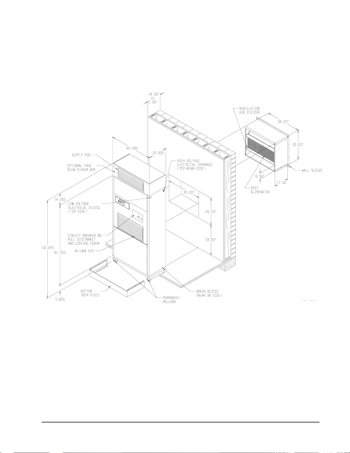
FIGURE 4
INSTALLATION OF UNIT THRU WALL WITH WALL SLEEVE
MIS-1564
Manual 2100-416
Page 7

FIGURE 5
INSTALLATION WITH FREE BLOW PLENUM
CEILING
20 IN.
MINIMUM
FIGURE 6
DUCTED APPLICATION
FIXED CEILINGSUSPENDED
CEILING
MIS-1558
FLOOR
DUCT
DUCT FLANGE
Manual 2100-416
Page 8
FLOOR
MIS-1559

DUCT WORK
Any heat pump is more critical of proper operating
charge and an adequate duct system than a straight air
conditioning unit. All duct work must be properly
sized for the design air flow requirement of the
equipment. Air Conditioning Contractors of America
(ACCA) is an excellent guide to proper sizing. All duct
work or portions thereof not in the conditioned space
should be properly insulated in order to both conserve
energy and prevent condensation or moisture damage.
When duct runs through unheated spaces, it should be
insulated with a minimum of one inch of insulation.
Use insulation with a vapor barrier on the outside of the
insulation. Flexible joints should be used to connect
the duct work to the equipment in order to keep the
noise transmission to a minimum.
EC
The QT
air duct to the top of the unit. Duct connection size is
12 inches x 20 inches. The duct work is field supplied
and must be attached in a manner to allow for ease of
removal when it becomes necessary to slide the unit out
from the wall for service. See Figure 7 for suggested
attachment method.
NOTE: Unit cabinet, supply air duct and free blow
series unit has provision to attach a supply
plenum are approved for “0” clearance to
combustible material.
When used with a ducted supply, a QCX Cabinet
Extension can be used to conceal the duct work above
the unit to the ceiling. This extends 20” above the unit
for a total height above the floor of 10’-7/8”. See
Optional Accessories, Page 18 for the correct Cabinet
Extension model number. The unit is equipped with a
variable speed indoor blower motor which increases in
speed with an increase in duct static pressure. The unit
will therefore deliver proper rated air flow up to the
Maximum ESP shown in Table 5. However, for quiet
operation of the air system, the duct static should be
kept as low as practical, within the guidelines of good
duct design.
FILTERS
Two 1 inch throw away filters are supplied with each
unit. The filters fit into a fixed rack.
The filters are serviced from the inside of the building .
To gain access to the filters release the latch on the
circuit breaker door and one 1/4 turn fastener near the
bottom of the door. This door is hinged on the left so it
will swing open.
The internal filter brackets are adjustable to
accommodate 2 inch filters. The tabs for the 1 inch
filters must be bent down to allow the 2 inch filters to
slide in place.
FIGURE 7
SUPPLY DUCT CONNECTIONS
SUPPLY DUCT
TO BE FIELD
SUPPLIED
ATTACHMENT
SCREWS TO BE
FIELD SUPPLIED
ROOM SIDE
OF QC UNIT
MIS-978
DUCT FLANGE
PROVIDED WITH UNIT
The QTEC series units are designed for use with free
return (non-ducted) and either free blow with the use of
QPB Plenum Box or a duct supply air system.
The QPB Plenum Box mounts on top of the unit and
has both vertically and horizontally adjustable louvers
on the front discharge grille. See Optional Accessories,
Page 18, for the correct Plenum Box model number.
FIGURE 8
FILTER LOCATION
FILTERS
RETURN AIR
GRILLE
Manual 2100-416
Page 9

CONDENSATE DRAIN
The condensate drain hose is routed down from the
evaporator drain pan on the right side of the unit into
the compressor compartment. There are three
locations that the drain can exit the cabinet. For a
stand pipe type of drain, the drain hose can exit the
rear of the cabinet. There is adequate hose length to
reach the floor on the right hand side of the unit.
If the drain is to be hard plumbed, there is a 3/4 inch
pipe connection located on the right hand cabinet
side near the rear and one on the cabinet rear panel.
In these installations the drain tube is to be slipped
over the pipe connection inside of the cabinet.
FIGURE 9A
SIDE DRAIN (SIDE VIEW)
QTEC UNIT
See Figures 9A, 9B and 9C.
NOTE: Whichever type of drain connection is used a
“P” trap must be formed.
The side drain requires a water trap for proper drainage.
See Figure 8A. The drain can be routed through the floor
or through the wall.
If the drain is to be routed through
an unconditioned space, it must be protected from
freezing
. The drain line must be able to be removed from
the unit if it is necessary to remove the unit from the wall.
FIGURE 9C
REAR DRAIN (TOP VIEW)
DRAIN LINE
SLEEVE
WALL
(MAXIMUM 10”
FOR REAR
DRAIN)
COUPLINGS NOT
SHOWN BUT
RECOMMENDED
FOR EASE OF
REMOVABILITY
FOR SERVICE
MIS-976
OPTIONAL REAR DRAIN
MIS-974
Manual 2100-416
Page 10
FIGURE 9B
WATER
TRAP
MIS-977
WALL
BRACKET
UNIT

The rear drain can be used with wall thickness of up to
10 inches where a water trap can be installed between
the unit and the interior wall. See Figure 8B. The trap
cannot extend beyond the edge of the unit or it will
interfere with the wall mounting bracket. The drain can
be routed through the floor or through the wall. If the
drain is routed through the wall, the drain line must be
positioned such that it will not interfere with the sleeve
flange or the grille. See Figure 9C on Page 10. If the
drain is to be routed through an unconditioned space,
it must be protected from freezing.
BAROMETRIC FRESH AIR DAMPER (Optional)
Before start to remove make sure the power has been
turned off. The hinged return air grille panel must be
opened. The fresh air damper assembly can be seen on
the back of the unit. Refer to Figure 10.
1. The fresh air damper is attached to the back of the
unit with one screw on either side of the assembly.
Both of the screws must be removed.
2. Once the mounting screws are removed, tilt the
assembly down and lift it out.
MIST ELIMINATOR SERVICE (Optional –
only used with one of the vent options)
A mist eliminator is supplied with the wall sleeve. The
mist eliminator is constructed of aluminum frame and
mesh. The mist eliminator is located in the top section
of the wall sleeve and can be removed from the inside
of the building without removing the unit from the wall.
This requires that the ventilation package must be
removed.
The steps necessary to remove each of the vent options
are listed following.
It is recommended that the mist eliminator be inspected
annually and serviced as required. The mist eliminator
can be inspected from the outside of the building by
looking through the outdoor grille. The mist eliminator
can be serviced from the outside. The outdoor grille
must be removed to do so.
The mist eliminator can be cleaned by washing with
soap and water. The excess water should be shaken off
the mist eliminator before it is reinstalled.
The mist eliminator can be seen through the opening.
The mist eliminator must be raised up and the bottom
can be pulled toward the front of the unit.
COMMERCIAL ROOM VENTILATOR OPTION
Before stating the removal make sure the power has
been turned off. The hinged return air grille must be
opened. The commercial room ventilator (CRV) can
be seen after the panel has been removed. The CRV
must be removed to gain access to the mist eliminator.
1. The two mounting screws in the front of the CRV
must be removed.
2. The power connectors for the CRV (located on the
right side of the unit) must be disconnected.
Squeeze the tabs on the sides of the connector and
pull straight out. Unplug both of the connectors.
3. Slide the CRV straight out of the unit.
The mist eliminator can be seen through the opening in
the back of the unit. The mist eliminator must be
raised up and the bottom can be pulled toward the front
of the unit and removed.
Manual 2100-416
Page 11

FIGURE 10
FRESH AIR DAMPER REMOVAL
MOUNTING SCREW
Manual 2100-416
Page 12
MIS-1627

QTEC ENERGY RECOVERY VENTILATOR
OPTION
Before starting the removal make sure that the power
has been turned off. The hinged return air grille panel
must be opened. The energy recovery ventilator
(QERV) can be seen after the panel is opened. To gain
access to the mist eliminator, the QERV must be
removed. Refer to Figure 11
1. The front fill plate of the QERV must be removed.
There is one screw on either side of the plate.
Remove these screws and remove the plate.
2. On either side of the QERV there are mounting
screws that hold the QERV in place. Remove both
of these screws.
REMOVAL OF THE QTEC ENERGY RECOVERY VENTILATOR
3. Underneath the heat recovery cassette there is a
power connector for the lower blower assembly. To
disconnect this plug, the tabs on both sides of the
plug must be squeezed to release the plug. While
squeezing the tabs, pull the plug out of the socket.
4. The QERV is plugged into the unit on the right side
of the unit. Both of these plugs must be
disconnected to remove the QERV. Squeeze the
tabs on the sides of the connector and pull straight
out.
5. Slide the QERV assembly straight out of the unit
being careful not to let the cassette slide out of the
QERV.
The mist eliminator can be seen through the opening in
the back of the unit. The mist eliminator must be raised
up and the bottom can be pulled toward the front of the
unit and removed.
FIGURE 11
MOUNTING
SCREWS
POWER
CONNECTORS
LOWER BLOWER
ASSEMBLY POWER
CONNECTOR
FRONT FILL
MIS-1605
Manual 2100-416
Page 13

INSTALLATION INSTRUCTIONS
MOUNTING THE UNIT
When installing a QC unit near an interior wall on the
left side, a minimum of 8 inches is required; 12 inches
is preferred.
When installing a QC unit near an interior wall on the
right side, a minimum of 12 inches is required as
additional space is required to connect the drain.
This clearance is required to allow for the attachment of
the unit to the wall mounting brackets and the side trim
pieces to the wall.
This unit is to be secured to the wall with the wall
mounting brackets provided. The unit itself, the supply
duct, and the free blow plenum are suitable for “0”
clearance to combustible material.
NOTE: When a wall sleeve is to be used discard the
brackets shipped with the heat pump and
attache the unit to the sleeve with bracket
supplied with the wall sleeve.
Following are the steps for mounting the QC units for
reference see Figure 13.
1. Attach wall mounting bracket to the structure wall
with field supplied lag bolts. The fluid piping
connections are to be within the confines of this
bracket. See Figure 1 for cabinet openings and
location of fluid coil connection points.
7. Position side trim pieces to the wall and attach with
field supplied screws. There are two long and two
short pieces supplied. The long pieces are to
enclose the gap behind the unit. The short pieces
are to fill the gap behind the cabinet extension or the
free blow plenum box. They may be cut to suit the
ceiling height or overlap the unit side trim. There is
sufficient length to trim up to a 10’2” ceiling.
FIGURE 12
REMOVING LOCKING SCREWS FROM WHEELS
2. Position the unit in front of the wall mounting
bracket.
3. Remove the locking screws from the wheels. Refer
to Figure 11.
4. Roll the unit up to the wall mounting bracket. The
unit must be level from side to side. If any
adjustments are necessary, shim up under the rollers
with sheets of steel or any substance that is not
affected by moisture.
5. Secure the unit to the wall bracket with provided
#10 hex head sheet metal screws. There are
prepunched holes in the cabinet sides, and the
bracket has slotted holes to allow for some
misalignment.
6. Position the bottom trim piece to the unit and attach
with provided screws (dark colored).
Manual 2100-416
Page 14
REMOVE SCREWS
FROM WHEELS
BEFORE ROLLING
INTO PLACE
MIS-1523

FIGURE 13
UNIT MOUNTING WITHOUT VENTILATION WALL SLEEVE
(REFER TO MOUNTING INSTRUCTIONS ON PAGE 13)
SIDE TRIM
(2 PIECES)
SIDE TRIM (2
PIECES)
BOTTOM TRIM PIECE
WALL MOUNTING
BRACKET
MIS-1557
BOTTOM TRIM
EXTENSION
Manual 2100-416
Page 15

FIGURE 14
COMPONENT LOCATION
SIDE FIELD
WIRE ENTRANCE
REMOTE THERMOSTAT
TERMINAL BLOCK
INDOOR BLOWER
CONTROL BOX/ CIRCUIT
BREAKER PANEL
WIRING – MAIN POWER
Refer to the unit rating plate and/or Table 2 for wire
sizing information and maximum fuse or “HACR
Type” circuit breaker size. Each unit is marked with a
“Minimum Circuit Ampacity”. This means that the
field wiring used must be sized to carry that amount of
current. Depending on the installed KW of electric
heat, there may be two field power circuits required. If
this is the case, the unit serial plate will so indicate. All
models are suitable only for connection with copper
wire. Each unit and/or wiring diagram will be marked
Manual 2100-416
Page 16
MIS-1736
“Use Copper Conductors Only”. These instructions
must be
adhered to. Refer to the National Electrical
Code (NEC) for complete current carrying capacity data
on the various insulation grades of wiring material. All
wiring must conform to NEC and all local codes.
The electrical data lists fuse and wire sizes (75° C
copper) for all models, including the most commonly
used heater sizes. Also shown are the number of field
power circuits required for the various models with
heaters.
The unit rating plate lists a “Maximum Time Delay
Relay Fuse” or “HACR Type” circuit breaker that is to
be used with the equipment. The correct size must be
used for proper circuit protection, and also to assure that
there will be no nuisance tripping due to the momentary
high starting current of the compressor motor.
The disconnect access door on this unit may be locked
to prevent unauthorized access to the disconnect.
The field wiring connections are located behind the top
panel in the circuit breaker panel. The return air panel
must be removed first. This panel is equipped with a
door switch which shuts the unit down when it is
removed. The filter rack must be removed next.
WIRING – LOW VOLTAGE WIRING
The Climate Control Option D is an electronic,
programmable thermostat. The subbase of the
thermostat is factory wired to the front panel of the unit.
Compatible for use with Energy Recovery Ventilator or
Economizer.
GENERAL
This unit is equipped with a variable speed ECM motor.
The motor is designed to maintain rated airflow up to
the maximum static allowed. It is important that the
blower motor plugs are not plugged in or unplugged
while the power is on. Failure to remove power prior
to unplugging or plugging in the motor could result in
motor failure.
230/208V, 1 PHASE AND 3 PHASE EQUIPMENT
DUAL PRIMARY VOLTAGE TRANSFORMERS
All equipment leaves the factory wired on 240V tap.
For 208V operation, reconnect from 240V to 208V tap.
The acceptable operating voltage range for the 240 and
208V taps are as noted in Table 3.
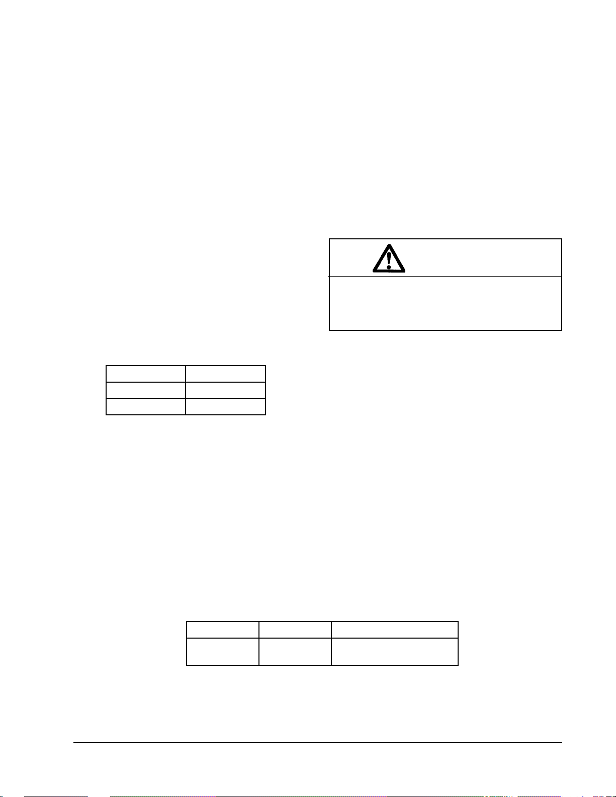
TABLE 3
OPERATING VOLTAGE RANGE
PATEGNAR
V042612-352
V802781-022
NOTE: The voltage should be measured at the field
power connection point in the unit and while
the unit is operating at full load (maximum
amperage operating condition).
The standard Climate Control Option X is a remote
thermostat connection terminal block. See Figure 17
for wiring diagram. Compatible thermostats are listed
in Table 4.
CAUTION
Do not plug in or unplug blower motor connectors while the power is on. Failure to do so
may result in motor failure.
FLUID CONNECTIONS
See Figure 1 for location of fluid connection.
Connection size is 1” FPT.
If the free blow plenum box is to be used, there are
knock outs in the top of the box that can be removed to
allow passage of the fluid piping.
All plumbing to and from the unit is to be installed in
accordance with local plumbing codes. The use of
plastic pipe where permissible is recommended to
prevent electrolytic corrosion of the fluid pipes.
It is strongly recommended that the fluid piping to the
unit be insulated to prevent water droplets from
condensing on the pipe surface.
TABLE 4
WALL THERMOSTATS AND SUBBASE COMBINATIONS
tatsomrehTesabbuSserutaeFtnanimoderP
940-3048
)083-39FI(
A/N
looC/taeH/otuA/launaM
cinortcelEelbammargorP
Manual 2100-416
Page 17
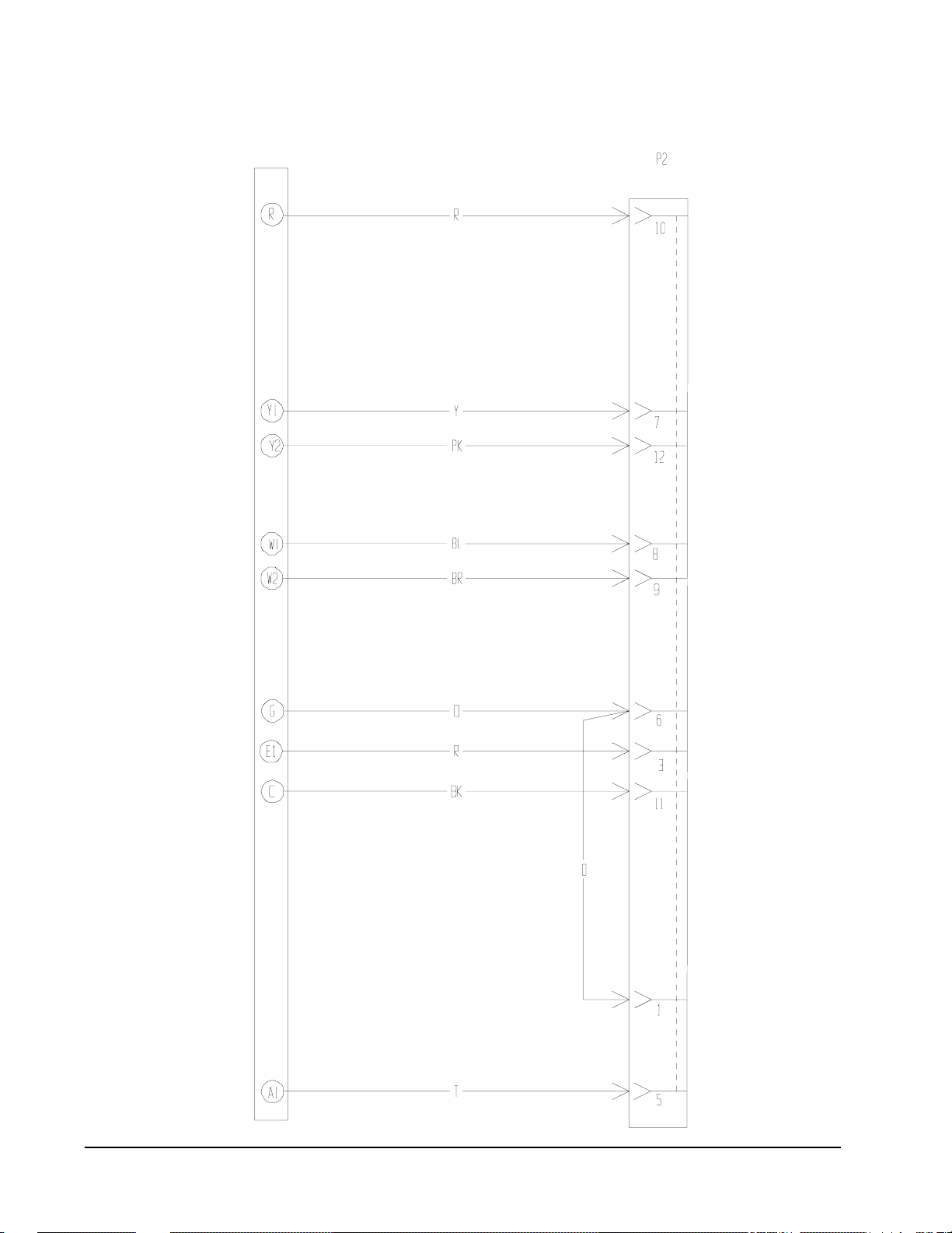
LOW VOLTAGE CONNECTIONS
These units use a grounded 24 volt AC low voltage
circuit.
The “R” terminal is the hot terminal and the “C”
terminal is grounded.
“G” terminal or pins 6 and 1 of P2 are the fan inputs.
Both must be energized for proper fan operation. This
is done automatically in the factory installed climate
control options. If the climate control option is
abandoned and connections are made directly to P2
both pins 6 and 1 of P2 must be energized for proper
operation.
“Y” terminal or pin 7 of P2 is the first stage cooling
input.
“B” terminal or pin 8 of P2 is the first stage heating
input.
“R” terminal or pin 10 of P2 is 24 VAC hot.
“C” terminal or pin 11 of P2 is 24 VAC grounded.
“L” terminal or pin 12 of P2 is the second stage
cooling input.
“W2” terminal or pin 9 of P2 is second stage heating
output.
“O1” terminal of pin 5 of P2 is the ventilation input.
This terminal energizes any factory installed ventilation
option.
LOW VOLTAGE CONNECTIONS FOR
DDC CONTROL
Fan Only Energize G
1st Cooling Mode Energize Y, G
2nd Cooling Mode Energize Y, L, G
1st Stage Heating Energize G, B
2nd Stage Heating Energize G, B, W2
Ventilation Energize G, O1
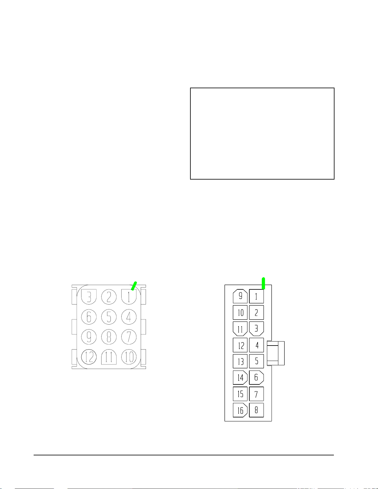
BLOWER MOTOR LOW VOLTAGE
VIEWED FROM PIN END
FIGURE 15
WIRE HARNESS PLUG
VIEWED FROM PIN END
MIS-1285
Manual 2100-416
Page 18

IF93-380
FIGURE 16
REMOTE THERMOSTAT WIRING DIAGRAM
“X” OPTION
MIS-1734
Manual 2100-416
Page 19
IF93-380
FIGURE 17
REMOTE THERMOSTAT WIRING DIAGRAM
“D” THERMOSTAT OPTION
Manual 2100-416
Page 20
4102-028
START UP
OPTIONAL CFM
These units are shipped from the factory set to operate
at the optional CFM level shown in Table 4. This
provides lower operating sound levels for non-ducted,
free discharge applications. This CFM level will reduce
the system capacity performance by approximately 2%
at the same energy efficiency.
Rated CFM is required for ducted applications for
maximum performance rating. To obtain full CFM on
these models, connect jumper wire as follows:
1. Disconnect all power to the unit. Failure to do so
may result in damage to the motor.
2. Open hinged return air grille panel
3. Open control panel cover.
4. Add pink jumper wire (provided) to terminal
5 and 6 on the terminal board.
5. Reverse steps to reassemble.
IMPORTANT INSTALLER NOTE
For improved start up performance, wash the indoor
coil with dishwashing detergent.
SERVICE HINTS
1. Caution user to maintain clean air filters at all times.
Also, not to needlessly close off supply air registers.
This may reduce air flow through the system which
shortens equipment service life as well as increasing
operating costs and noise levels.
2. The wall thermostat perform multiple functions. Be
sure that all function switches are correctly set for
the desired operating mode before trying to
diagnose any reported service problems.
SEQUENCE OF OPERATION
FIRST STAGE COOLING – Circuit R-Y makes the
thermostat open the first stage cooling water valve.
SECOND STAGE COOLING – Circuit R-Y2 make
the thermostat open the second stage cooling water
valve. The G (indoor motor) circuit is automatically
completed on any call for cooling operation, or can be
energized by manual fan switch on subbase for constant
air circulation.
Caution: Second stage cooling must always be
energized in conjunction with first stage. If
the second state were energized alone, the
condensate from the upper part of the coil
could be blow off or re-evaporated as it
passes down over the dry portion of the
coil.
HEATING – A thermostat demand for heating makes
R-W1 circuit as well as R-G circuit. This starts the
indoor blower as well as turns on the electric heater.
SECOND STAGE HEATING (15 KW only) – Circuit
R-W2 energizes the second contactor and brings on the
last 5 KW of heat.
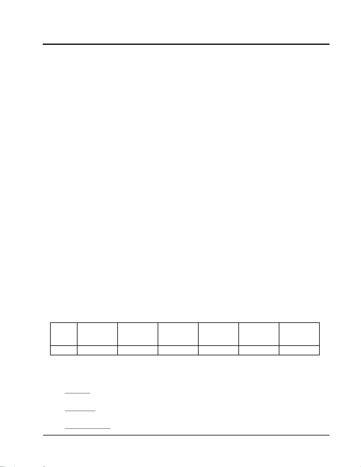
TABLE 5
INDOOR BLOWER PERFORMANCE
1
DETAR
LEDOM
105CQ0.08.00021000100015711
NOTE: These units are equipped with a variable speed (ECM) indoor motor that automatically
j Maximum ESP (inches WC) shown is with 1” thick disposable filter (reduced by .2 for 2” filter).
k Rated CFM for ducted applications – required for maximum performance rating. To obtain full CFM locate low
voltage terminal strip in the circuit breaker box.There is a pink jumper wire with both ends attached to terminal
marked “G2”. Move one end of the jumper to terminal “Y”.
l Optional CFM – the unit is shipped from the factory set to operate at the optional CFM level shown.
This provides lower operating sound levels for non-ducted, free discharge applications. This reduces
system capacity performance by approximately 2% at the same energy efficiency.
m Continuous fan CFM is the total air being circulated during continuous fan mode.
PSE
adjusts itself to maintain approximately the same rate of indoor air flow in both heating
and cooling, dry and wet coil conditions, and at both 230/208 or 460 volts.
PSE.XAM
2
3
LANOITPO
MFCDETAR
MFC
4
@
MFC
SUOUNITNOC
MFC
Manual 2100-416
Page 21
PSE
.XAM
y
TROUBLESHOOTING ECM BLOWER MOTORS
CAUTION
Disconnect power from unit before removing or replacing connectors, or servicing motor.
Wait at least 5 minutes after disconnection power before opening motor.
MOTPMYS ERUDECORP/ESUAC
.gnitratsnehwylthgilsskcorrotoM
tratst'nowrotoM
%
tnemevomoN
%
%
%
%
%
%
%
%
nuR kcehCerutisoM
MCIrofpu-tratslamronsisihT
rotomtarewopkcehC
tfahsthgitrofrotomkcehC
rotomta)CotRCAV42(egatlovwolkcehC
rotomta)C,R,W,Y,G(snoitcennocegatlovwolkcehC
ssenrahrotomnosrotcennocnisnipdetaesnurofkcehC
G-RneewtebrepmujyraropmetahtiwtseT
%
rewolbfoffodetset
%
%
%
%
ODT'NOD
%
%
"spoolpird"llatsni
%
tnemecalperrof
%
– sretlifcitatswol,ycneiciffehgihdnemmoceR
– naelcsretlifgnipeekdnemmoceR
– ,citatsmuminimrofkrowtcudngiseD
– krowtcuddnemmocerdnarofkooL
tratst'nowtub,skcorrotoM
gniebelihwnwoddnapusetallicsorotoM
tenibacforewolbysioN
)deeps(MFChgihta"sffup"ro"stnuH"
erutsioMfoecnedivE
dnaderuccosahnoitcnuflamfoeruliafrotoM
tneserpsierutsiom
revomriaedisnitneserperutsiomfoecnedivE
snoitcennocdnagniriw,slortnoc,rotomtuokcehC
rotomgnicalpererofebylhguoroht
;nitegt'nacretawosnwodsrotcennoctneirO
srebmunledomlortnocdnarotomdezirohtuaesU
:muminimaoterusserpcitatspeeK
trofmocmumixam
rassecenerehw,tnemevorpmi
.tnemecalperni,
%
%
%
%
%
– ,stcudnismaeshguorhtgniltsihwriarofkcehC
.slenaprostenibac
– noitamrofedtcud/tenibacrofkcehC
%
– noitcitserecudeR
– wolfriamumixamecudeR
%
%
%
%
%
%
%
mrofrepdnarotomecalpeR kcehCerutsioM
kcehCerutsioMmrofreP
snruterdetcirtseresU
tnuomrotomtnailpmocroesoolrofkcehC
tfahsnothgitsileehwrewolberusekaM
.tfahsnodaolonhtiwetallicsootrotomroflamronsitI
.cte,slenap,gnisuohrewolbesoolrofkcehC
?deepsrewolbhgihgnitaerccitatshgiH
?"gniffup"ecuderretlifrolenapgnivomerseoD
dabsirotomehtemussayllacitamotuA
snoitsopksolc'o4dna7evobasrotcennocetacoL
rehtonahtiwrebmunledomlortnocforotomenoecalpeR
)tnemecalperdezirohtuanasselnu(
H"2/1evahemoS.sretlifporderusserphgihesU
2
!pordO
Manual 2100-416
Page 22

MOTPMYS ERUDECORP/ESUAC
yllacitarresnurtubstratsrotoM
%
%
%
MFCtaeh
tnettimretnironwoddnapuseiraV
)deeps(MFChgihta"sffupro"stnuH"
%
%
%
snoitacilppa
%
%
%
%
roloocrofllacmetssysetipsedMFCwoltasyatS
%
%
mrofreP kcehCerutsioM
–noitcirtserecudeR
–wolfriamumixamecudeR
etelpmoc
"gas"ronoitairavrofegatlovenilkcehC
;rotomta)C,R,W,Y,G(snoitcennocegatlovwolkcehC
srotcennocssenrahrotomnisnipdetaesnu
deepselbairavni(dnammocMFCcitarrerof"kB"kcehC
?tatsomreht-slortnocmetsystuokcehC
?"gniffup"ecuderretlifrolenapgnivomerseoD
snoitcennocdnaseriw)tatsomreht(egatlovwolkcehC
siyaledlitnutiaw-edomyaladnitonsinafyfireV
rotomtadetcennocton/gnissim"R"
kcehctnemecalperlortnoc/rotommrofreP
%
%
NOTPMYS ERUDECORP/ESUAC
%
ODT'NOD
%
%
esioNriA
MFChgihtasyatS
ffotuhst'nowrewolB
esionevissecxE
ylesiwtnempuqeehteziS
rotomgnitresnierofebnoitatneirokcehC
srotcennoc
%
%
%
–etatsdilosrotatsomrehtdehctiwscairTrofkcehC
yaler
%
%
–?ylreporpteswolfriasI
–?nwodwolsotrewolbesuacretlifgnivomerseoD
retlifecalper/kcehC
–retlifporderusserpwolesU
–snoitcritsertcudtcerroc/kcehC
%
%
%
sgulpecroF
rotomtadetcennocton/gnissim"R"
etelpmocemityaledlitnutiaw-?edomyaladninafsI
?WroY,GotnislortnocmorfegakaeltnerruC
.esionrotomrotcud,tenibac,esionriasitifienimreteD
.yrssecenfiremotsucweivretnI
?deepsrewolbhgihgnitaerccitatshgiH
wolfriawolhtiwetasnepmocnehtmetsysezisrevO
sdrawkcabrotcennocrewopnigulP
ERUDECORPKCEHCERUTSIOM ERUDECORPKCEHCTROFMOC
%
%
%
%
%
%
"nwod"detneiroerasrotcennoC
rotomrednu"poolpird"htiwsessenrahegnarrA
?deggulpniardetsnednoC
)yticapactnetalhcumoot(wolfriawolrofkcehC
noitidnocdegrahcrednurofkcehC
%
%
%
%
%
%
tenibacdnastcudnrtuerniskaelgulpdnakcehC
sgnitteswolfriareporpkcehC
esiontsewolroferusserpcitatswoL
MFCnafsuounitnocwolteS
stinugniloocdeeps-2dnatatsidimuhesU
MFCetalugertahtMCIrofdengisedslortnocgninozesU
?noitacoldabnitatsomrehT
Manual 2100-416
Page 23

Valve Location
FIGURE 18
INTERNAL 2-WAY VALVE PIPING
Water Valves
Valve Detail
"NC" side of valve
Manual 2100-416
Page 24
"COM" side of valve
"NO" side of valve
MIS-1899

Valve Location
FIGURE 19
INTERNAL 3-WAY VALVE PIPING
Water Valves
Valve Detail
"NC" side of valve
"COM" side of valve
"NO" side of valve
MIS-1900
Manual 2100-416
Page 25
 Loading...