

Bard QW242D, QW481D, QW601D, QW302D, QW361D Installation Instructions Manual
...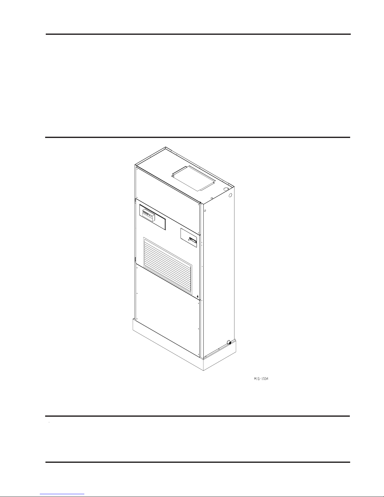
QW SERIES
WATER SOURCE
INSTALLATION
INSTRUCTIONS
PACKAGED HEAT PUMP
Models:
QW242D QW302D
QW361D QW421D
QW481D QW601D
Earth Loop Fluid
Temperatures 25 – 110
Ground Water Temperature 45 – 75
© Copyright 2003
Bard Manufacturing Company, Inc.
Bryan, Ohio 43506
Since 1914...Moving ahead, just as planned.
Manual No.: 2100-418F
Supersedes: 2100-418E
File: Vol II Tab 14
Date: 06-28-07
Manual 2100-418F
Page 1 of 49

CONTENTS
Getting Other Information and Publications
For more information, contact these publishers:...... 4
QW General Information
QW Model Nomenclature ........................................ 5
Shipping Damage .................................................... 7
Unit Removal From Skid .......................................... 7
Handling Unit After Removal From Skid .................. 7
Removal of Wall Bracket from Shipping Location ... 8
General .................................................................... 8
Minimum Installation Height..................................... 8
Duct Work ............................................................... 11
Filters ...................................................................... 11
Condensate Drain ........................................... 11 - 13
Mist Eliminator Service .......................................... 13
Installation Instructions
Mounting the Unit .................................................. 16
Wiring – Main Power ............................................. 19
Wiring – Low Voltage Wiring ................................. 19
General .......................................................... 19 & 20
Low Voltage Connections ...................................... 20
Start Up
Description of Standard Equipment ....................... 24
Compressor Control Module .................................. 24
Adjustments ........................................................... 24
Optional CFM ........................................................ 25
Important Installer Note ......................................... 25
Phase Monitor ....................................................... 25
Service Hints ......................................................... 25
Sequence of Operation .................................. 25 & 26
Optional Climate Controls Sequence of
Operation ....................................................... 26 & 27
Refrigerant Tube Schematic for Reheat Coil ......... 27
Pressure Service Ports .......................................... 27
Pressure Tables .............................................. 32 - 33
Optional Accessories ............................................. 34
Closed Loop (Earth Coupled Ground Loop Applications)
Circulation System Design .................................... 35
Copper Water Coil Application ............................... 35
Start Up Procedure for Closed Loop System ......... 36
Open Loop (Well System Applications)
Water Connections ................................................ 38
Copper Water Coil Limitations ....................... 38 & 39
Well Pump Sizing .................................................. 39
Start Up Procedure for Open Loop System ... 39 & 40
Water Corrosion .................................................... 40
Remedies of Water Problems................................ 40
Lake and Pond Installations .................................. 41
Cooling Tower / Boiler Application ......................... 43
Service
Service Hints ......................................................... 44
Unbrazing System Components ............................ 44
Troubleshooting GE ECM™ Blower Motors . 45 - 46
Quick Reference Troubleshooting Chart for
Water to Air Heat Pump .......................................... 47
Ground Source Heat Pump
Performance Report ........................................ 48 - 49
Manual 2100-418F
Page 2 of 49

CONTENTS
Figures
Figure 1 Unit Dimensions ..................................... 6
Figure 2 Removal of Unit From Skid .................... 7
Figure 3 Proper Handling of Unit After Removal
from Skid ................................................ 8
Figure 4 Installation of Unit w/Wall Sleeve .......... 9
Figure 5 Installation With Free Blow Plenum ..... 10
Figure 6 Ducted Application ............................... 10
Figure 7 Supply Duct Connections ..................... 11
Figure 8 Condensate Drain ................................ 12
Figure 8A Side Drain (Side View)......................... 12
Figure 8B Optional Rear Drain ............................. 12
Figure 8C Rear Drain (Top View).......................... 13
Figure 9 Fresh Air Damper Removal.................. 14
Figure 10 Removal of QT
Figure 11 Remove Locking Screws from Wheels 16
Figure 12 Unit Mounting Without Wall Sleeve ..... 17
Figure 13 Component Location ............................ 18
Figure 14 Low Voltage Wire Harness Plug .......... 20
Figure 15 Remote Thermostat Wiring "X" Option 21
Figure 16 Remote Thermostat Wiring "E" Option 22
Figure 17 Remote Thermostat Wiring "G" Option 23
Figure 18 Heat Pump Dehumidification Mode
Circuit Diagram .................................... 28
Figure 19 Heap Pump Cooling Mode Circuit
Diagram ............................................... 28
Figure 20 Fluid Connections w/Ventilation
Wall Sleeve .......................................... 30
Figure 21 Fluid Connections w/o Ventilation
Wall Sleeve .......................................... 31
Figure 22 Circulation System ............................... 35
Figure 23 Water Temperature and Pressure
Test Procedure .................................. 36
Figure 24 Performance Model WGPM-1C ........... 37
Figure 25 Performance Model WGPM-2C ........... 37
Figure 26 Piping Diagram .................................... 38
Figure 27 Cleaning Water Coil ............................. 41
Figure 28 Water Well System .............................. 42
Figure 29 Control Disassembly ............................ 46
Figure 30 Winding Test ........................................ 46
Figure 31 Drip Loop ............................................. 46
EC ERV ......................... 15
Tables
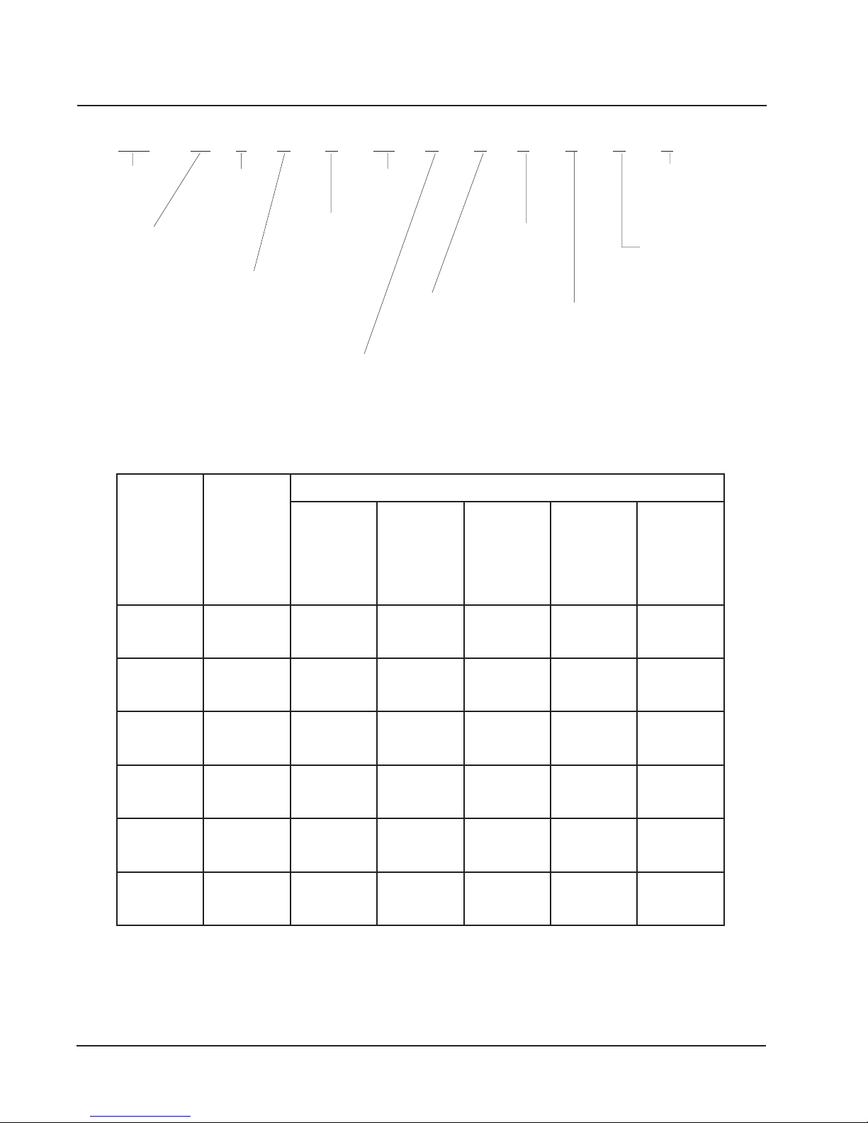
Table 1 Electrical Specifications ........................... 5
Table 2 Operating Voltage Range....................... 19
Table 3 Wall Thermostats ................................... 19
Table 4 Indoor Blower Performance ................... 27
Table 5 Dehumidification Relay Logic Board ...... 29
Table 6 Cooling Pressure Table .......................... 32
Table 7 Heating Pressure ................................... 33
Table 8 Optional Accessories ............................. 34
Table 9 Constant Flow Valves ............................. 38
Table 10 Water Flow and Pressure Drop .............. 43
Manual 2100-418F
Page 3 of 49

GETTING OTHER INFORMATION AND PUBLICATIONS
These publications can help you install the air
conditioner or heat pump. You can usually find these at
your local library or purchase them directly from the
publisher. Be sure to consult current edition of each
standard.
National Electrical Code ...................... ANSI/NFPA 70
Standard for the Installation .............. ANSI/NFPA 90A
of Air Conditioning and Ventilating Systems
Standard for Warm Air ...................... ANSI/NFPA 90B
Heating and Air Conditioning Systems
Load Calculation for Residential ....... ACCA Manual J
Winter and Summer Air Conditioning
Duct Design for Residential ............. ACCA Manual D
Winter and Summer Air Conditioning and Equipment
Selection
Closed-Loop/Ground Source Heat Pump ........ IGSHPA
Systems Installation Guide
Grouting Procedures for Ground-Source ......... IGSHPA
Heat Pump Systems
Soil and Rock Classification for the Design .... IGSHPA
of Ground-Coupled Heat Pump Systems
FOR MORE INFORMATION, CONTACT
THESE PUBLISHERS:
ACCA Air Conditioning Contractors of America
1712 New Hampshire Avenue
Washington, DC 20009
Telephone: (202) 483-9370
Fax: (202) 234-4721
ANSI American National Standards Institute
11 West Street, 13th Floor
New York, NY 10036
Telephone: (212) 642-4900
Fax: (212) 302-1286
ASHRAE American Society of Heating Refrigerating,
and Air Conditioning Engineers, Inc.
1791 Tullie Circle, N.E.
Atlanta, GA 30329-2305
Telephone: (404) 636-8400
Fax: (404) 321-5478
NFPA National Fire Protection Association
Batterymarch Park
P.O. Box 9101
Quincy, MA 02269-9901
Telephone: (800) 344-3555
Fax: (617) 984-7057
Ground Source Installation Standards ............. IGSHPA
Closed-Loop Geothermal Systems – Slinky .... IGSHPA
Installation Guide
Manual 2100-418F
Page 4 of 49
IGSHPA International Ground Source
Heat Pump Association
490 Cordell South
Stillwater, OK 74078-8018
QW SERIES WATER SOURCE GENERAL INFORMATION
QW MODEL NOMENCLATURE
QW 36 1 D A 0Z B X V X X X
MODEL NUMBER
QTEC Model Water
Source Heat Pump
CAPACITY
24 - 2 Ton
30 - 2½ Ton
36 - 3 Ton
42 - 3½ Ton
48 - 4 Ton
60 - 5 Ton
VENTILATION OPTIONS
B - Blank-off Plate
X - Barometric Fresh Air Damper (Standard)
V-
Commercial Ventilator - Motorized Spring Return w/Exhaust
P - Commercial Ventilator - Motorized Power Return w/Exhaust
R - Energy Recovery Ventilator w/Exhaust
REVISION
DEHUMIDIFICATION
KW
0Z - None
VOLTS & PHASE
A - 230/208-60-1
B - 230/208-60-3
C - 460-60-3
FILTER OPTIONS
X - 1-Inch Fiberglass
F - 2-Inch Fiberglass
P - 2-Inch Pleated
COLOR OPTIONS
V - Platinum w/Slate
4 - Gray (Painted)
(Standard)
TABLE 1
ELECTRICAL SPECIFICATIONS
Front (Vinyl)
CLIMATE CONTROL OPTIONS 1
X - None
E - Electronic/Prog/Man/Auto/Humidistat
F - Electronic Non-Prog/Man or Auto
C/O/Humidistat/6-hr. timer
G - Electronic Non-Prog/Man or Auto
C/O/Humidistat
TIUCRICELGNIS
INTERNAL CONTROLS
X - Standard
• High Pressure Switch
• Low Pressure Switch
• Compressor Time Delay
COIL OPTIONS
X - Standard Cupronickel
Water Coil
4 - Copper Water Coil
3
1
2
2
MUMIXAM
LANRETXE
DETAR
&STLOV
LEDOM
Z0AD242WQ
Z0BD242WQ
Z0CD242WQ
Z0AD203WQ
Z0BD203WQ
Z0CD203WQ
Z0AD163WQ
Z0BD163WQ
Z0CD163WQ
Z0AD124WQ
Z0BD124WQ
Z0CD124WQ
Z0AD184WQ
Z0BD184WQ
Z0CD184WQ
Z0AD106WQ
Z0BD106WQ
Z0CD106WQ
ESAHP
1-802/032
3-802/032
3-064
1-802/032
3-802/032
3-064
1-802/032
3-802/032
3-064
1-802/032
3-802/032
3-064
1-802/032
3-802/032
3-064
1-802/032
3-802/032
3-064
DLEIF.ON
REWOP
STIUCRIC
1
1
1
1
1
1
1
1
1
1
1
1
1
1
1
1
1
1
MUMINIM
TIUCRIC
YTICAPMA
91
41
8
12
61
01
42
91
01
72
02
11
13
42
21
54
43
61
ROESUF
TIUCRIC
REKAERB
52
02
51
03
02
51
53
52
51
04
03
51
54
53
51
06
54
02
DLEIF
REWOP
EZISERIW
01
21
41
01
21
41
01
01
41
8
01
41
8
8
41
8
8
21
DNUORG
EZISERIW
01
21
41
01
21
41
01
01
41
01
01
41
01
01
41
01
01
21
1 Maximum size of the time delay fuse or HACR type circuit breaker for protection of field wiring conductors.
2 Based on 75°C copper wire. All wiring must conform to the National Electrical Code and all local codes.
3 These “Minimum Circuit Ampacity” values are to be used for sizing the field power conductors. Refer to the National Electric
Code (latest revision), article 310 for power conductor sizing.
CAUTION: When more than one field power conductor circuit is run through one conduit, the conductors must be derated.
Pay special attention to Note 8 of Table 310 regarding Ampacity Adjustment Factors when more than three
conductors are in a raceway.
Manual 2100-418F
Page 5 of 49
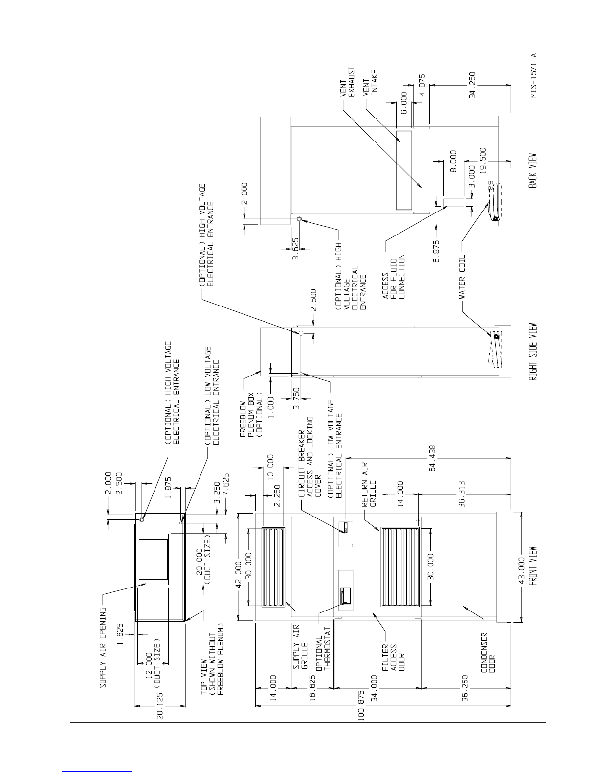
FIGURE 1
UNIT DIMENSIONS
Manual 2100-418F
Page 6 of 49
SHIPPING DAMAGE
Upon receipt of equipment, the carton should be
checked for external signs of shipping damage. The
skid must remain attached to the unit until the unit is
ready for installation. If damage is found, the receiving
party must contact the last carrier immediately,
preferably in writing, requesting inspection by the
carrier’s agent.
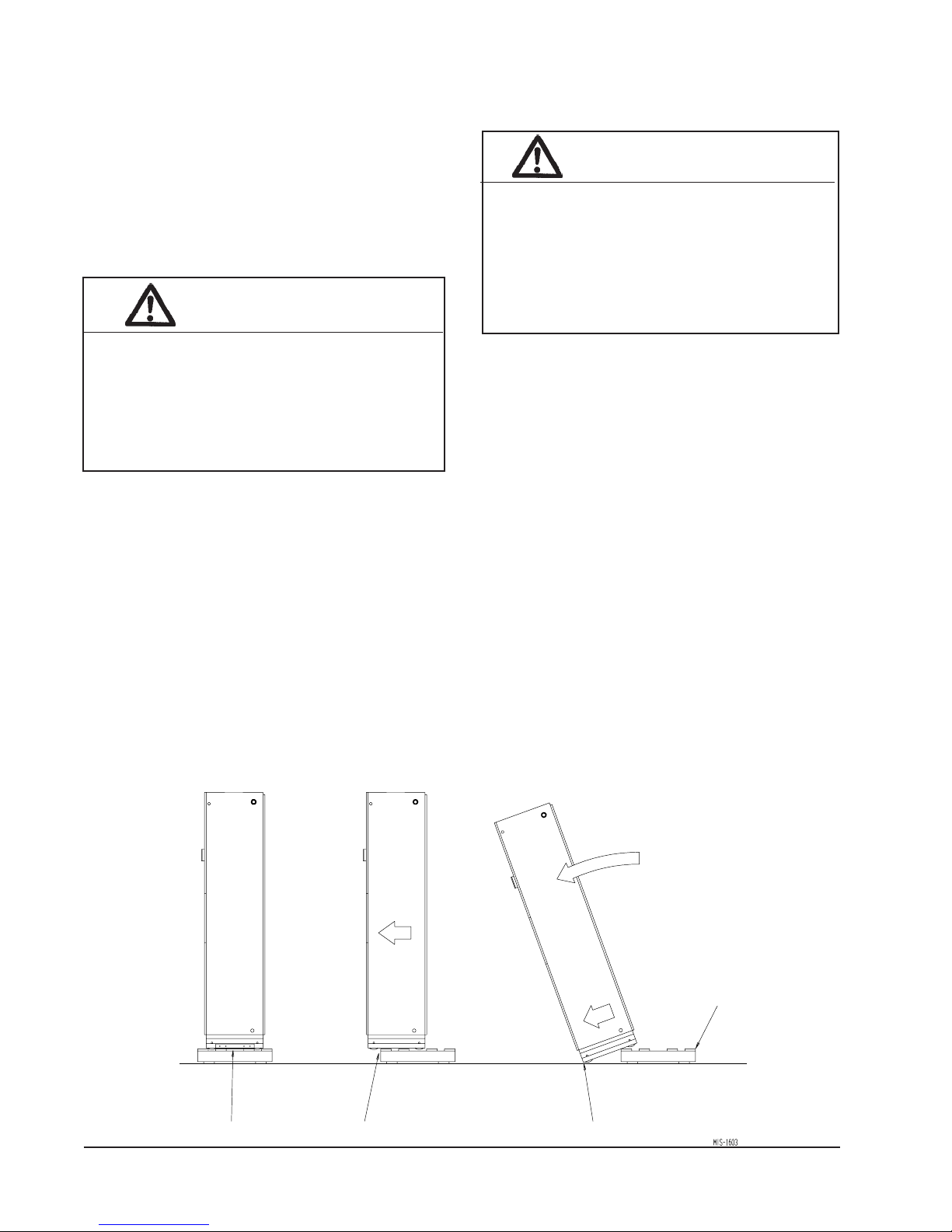
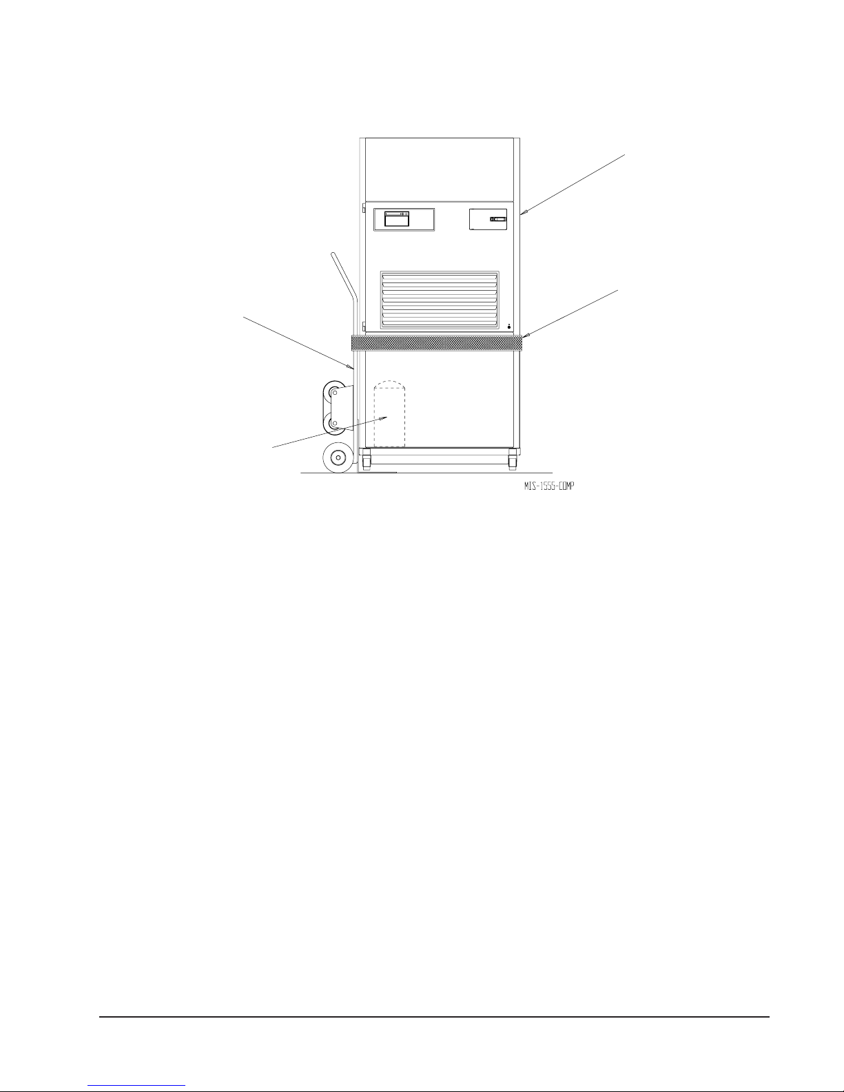
UNIT REMOVAL FROM SKID
WARNING
HANDLING UNIT AFTER REMOVAL FROM
SKID
WARNING
Exercise extreme caution when pushing the
unit on the rollers. Handle and push from the
lower 1/3 of the unit. Insure that debris is not
on the floor where the unit is to be moved on
the rollers. Failure to do so could result in
the unit tipping over and causing bodily injury
and/or damage to the unit.
This unit is heavy and requires more than one
person to handle and remove from the skid.
Check unit wheels to ensure that wheels are
locked before removing from skid. Extreme
caution must be taken to prevent injury to
personnel and damage to the unit.
It is recommended that the unit not be removed from the
skid with a forklift.
The shipping brackets on each side of the unit must be
removed and discarded. See Figure 2-A on Page 7. The
return air grille panel can be removed to provide a place
to hold the unit. The unit can be slid forward on the
skid until the front wheels hang over the edge of the
skid. See Figure 2-B. The unit can be tipped forward
and slid down the edge of the skid until the front wheels
touch the ground. See Figure 2-C. The wheels will not
roll. They are shipped from the factory locked so they
will not roll. The back of the skid will have to be held
down to keep it from tipping up. The skid can be slid
out from under the unit. The unit can then be set
upright.
REMOVAL OF UNIT FROM SKID
The unit will have to be turned sideways and removed
from the skid to fit through a 36" doorway. If the door
height allows, the unit can be slid sideways through the
door.
If the unit can not be slid through the door, then the unit
will have to be put on a cart and tipped down to roll
through the door. It is recommended that an appliance
cart by used with a strap to hold the unit on the cart.
The wheels of the unit must be locked. If the wheels
were allowed to roll, the unit could roll off the cart. The
unit should always be carted from the left side. This is
the side where the compressor is located. See Figure 3.
The blade of the appliance cart should be slid under the
wheels of the unit. The strap of the appliance cart
should be placed around the unit and strapped tightly.
Help will be required to tip the unit back onto the cart.
The unit can be leaned far enough back to be rolled
through the door. Be careful when setting the unit back
up to keep from damaging the unit.
FIGURE 2
A SHIPPING BRACKETS B FRONT WHEELS OVER EDGE C FRONT WHEELS ON FLOOR
HOLD SKID DOWN
Manual 2100-418F
Page 7 of 49
APPLIANCE
CART
COMPRESSOR
FIGURE 3
PROPER HANDLING OF UNIT
AFTER REMOVAL FROM SKID
QT
EC
UNIT
(RIGHT SIDE)
STRAP
REMOVAL OF WALL BRACKET FROM
SHIPPING LOCATION (UNITS WITH
BLANK OFF PLATE ONLY)
The wall brackets are attached to the back of the unit.
Remove and retain the wall brackets for use when
attaching the unit to the wall. In units equipped with a
ventilator a wall sleeve is required and these two wall
brackets are not included. A different style bracket is
supplied with the sleeve assembly.
GENERAL
The equipment covered in this manual is to be installed
by trained, experienced service and installation
technicians.
The unit is designed for use with or without duct work.
For use without duct work, Plenum Box QPB** is
recommended.
These instructions explain the recommended method to
install the water source self-contained unit and the
electrical wiring connections to the unit.
These instructions and any instructions packaged with
any separate equipment required to make up the entire
air conditioning system should be carefully read before
beginning the installation. Note particularly “Start
Procedure” and any tags and/or labels attached to the
equipment.
While these instructions are intended as a general
recommended guide, they do not supersede any national
and/or local codes in any way. Authorities having
jurisdiction should be consulted before the installation is
made. See Page 4 for information on codes and
standards.
Size of unit for a proposed installation should be based
on heat loss calculation made according to methods of
Air Conditioning Contractors of America (ACCA). The
air duct should be installed in accordance with the
Standards of the National Fire Protection Systems of
Other Than Residence Type, NFPA No. 90A, and
Residence Type Warm Air Heating and Air
Conditioning Systems, NFPA No. 90B. Where local
regulations are at a variance with instructions, installer
should adhere to local codes.
MINIMUM INSTALLATION HEIGHT
The minimum installation height of the unit with a Free
Blow Plenum is 8 ft. 6 in. This provides enough
clearance for the plenum to be removed. See Figure 5.
The minimum installation height for ducted applications
is 8 ft. 4½ in. This provides enough clearance to install
the duct work. See Figure 6.
Manual 2100-418F
Page 8 of 49
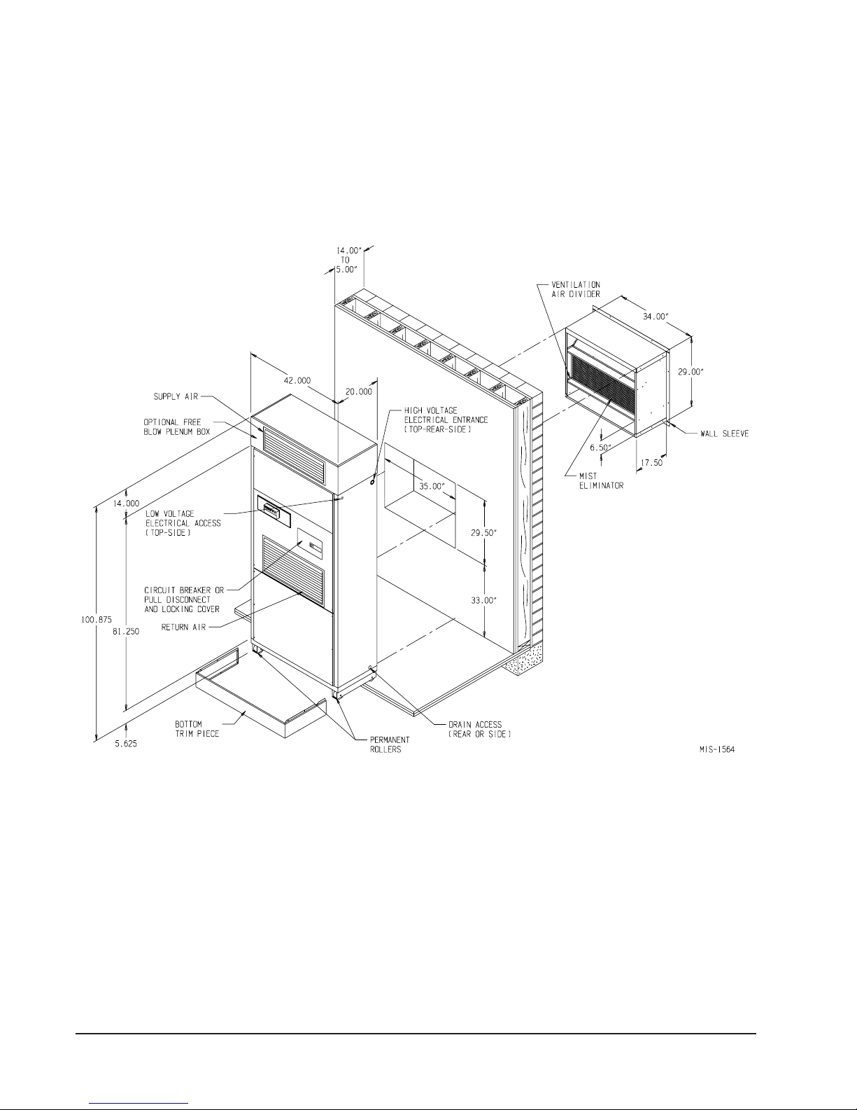
FIGURE 4
INSTALLATION OF UNIT THROUGH WALL WITH WALL SLEEVE
Manual 2100-418F
Page 9 of 49
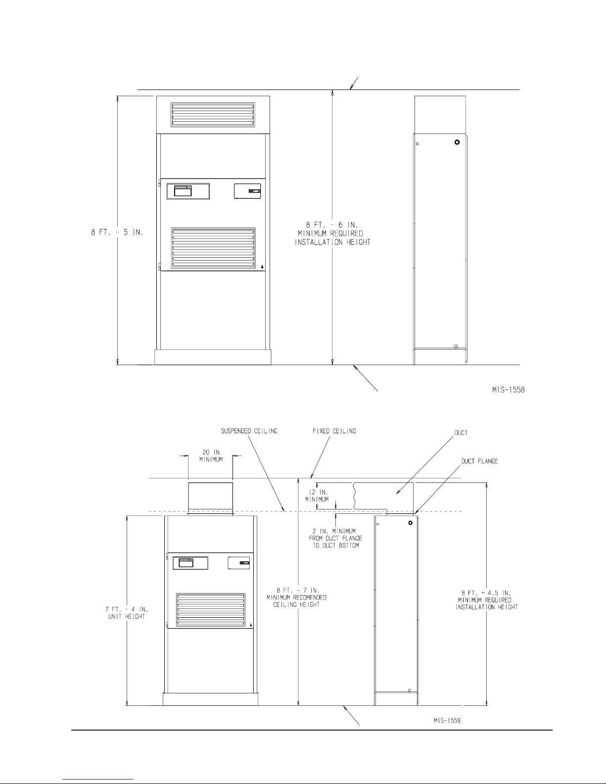
FIGURE 5
INSTALLATION WITH FREE BLOW PLENUM
CEILING
FIGURE 6
DUCTED APPLICATION
FLOOR
Manual 2100-418F
Page 10 of 49
FLOOR
DUCT WORK
Any heat pump is more critical of proper operating
charge and an adequate duct system than a straight air
conditioning unit. All duct work must be properly sized
for the design airflow requirement of the equipment.
Air Conditioning Contractors of America (ACCA) is an
excellent guide to proper sizing. All duct work or
portions thereof not in the conditioned space should be
properly insulated in order to both conserve energy and
prevent condensation or moisture damage. When duct
runs through unheated spaces, it should be insulated
with a minimum of one inch of insulation. Use
insulation with a vapor barrier on the outside of the
insulation. Flexible joints should be used to connect the
duct work to the equipment in order to keep the noise
transmission to a minimum.
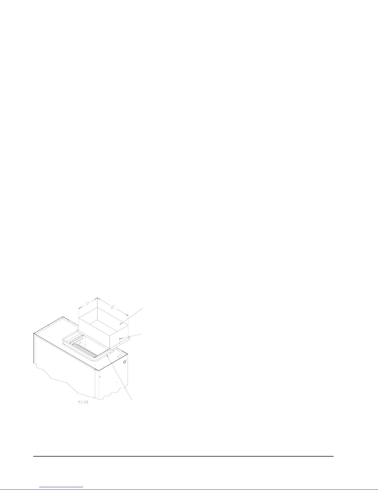
The QTEC series heat pump has provision to attach a
supply air duct to the top of the unit. Duct connection
size is 12 inches x 20 inches. The duct work is field
supplied and must be attached in a manner to allow for
ease of removal when it becomes necessary to slide the
unit out from the wall for service. See Figure 7 for
suggested attachment method.
NOTE: Unit cabinet, supply air duct and free blow
plenum are approved for “0” clearance to
combustible material.
EC
The QT
series heat pumps are designed for use with
free return (non-ducted) and either free blow with the
use of QPB Plenum Box or a duct supply air system.
The QPB Plenum Box mounts on top of the unit and has
both vertically and horizontally adjustable louvers on
the front discharge grille.
When used with a ducted supply, a QCX Cabinet
Extension can be used to conceal the duct work above
the unit to the ceiling. This extends 20" above the unit
for a total height above the floor of 10'-7/8". The unit is
equipped with a variable speed indoor blower motor,
which increases in speed with an increase in duct static
pressure. The unit will therefore deliver properly rated
airflow up to the Maximum ESP shown in Table 4.
However, for quiet operation of the air system, the duct
static should be kept as low as practical, within the
guidelines of good duct design.
FILTERS
Two 1-inch throw away filters are supplied with each
unit. The filters fit into a fixed rack.
The filters are serviced from the inside of the building .
To gain access to the filters release the latch on the
circuit breaker door and one 1/4 turn fastener near the
bottom of the door. This door is hinged on the left so it
will swing open.
ROOM SIDE
OF QW UNIT
FIGURE 7
SUPPLY DUCT CONNECTIONS
SUPPLY DUCT
TO BE FIELD
SUPPLIED
ATTACHMENT
SCREWS TO BE
FIELD SUPPLIED
DUCT FLANGE
PROVIDED WITH UNIT
The internal filter brackets are adjustable to
accommodate 2-inch filters. The tabs for the 1-inch
filters must be bent down to allow the 2-inch filters to
slide in place.
CONDENSATE DRAIN
The condensate drain hose is routed down from the
evaporator drain pan on the right side of the unit into the
compressor compartment. There are three locations that
the drain can exit the cabinet. For a stand pipe type of
drain, the drain hose can exit the rear of the cabinet.
There is adequate hose length to reach the floor on the
right hand side of the unit.
If the drain is to be hard plumbed, there is a 3/4 inch
pipe connection located on the right hand cabinet side
near the rear and one on the cabinet rear panel. In these
installations the drain tube is to be slipped over the pipe
connection inside of the cabinet.
See Figures 8A, 8B and 8C.
NOTE: Whichever type of drain connection is used a
“P” trap must be formed. See Figure 8.
Manual 2100-418F
Page 11 of 49
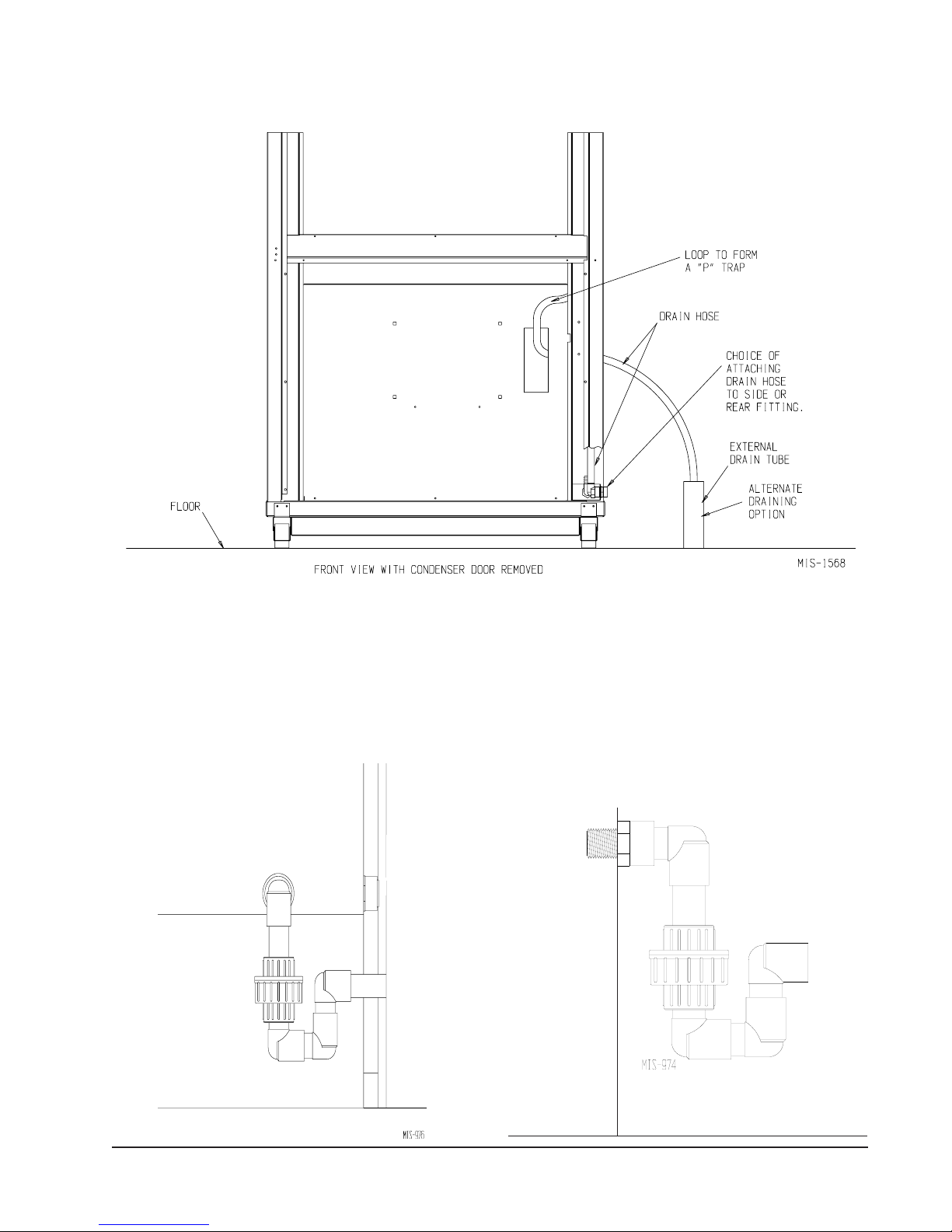
FIGURE 8
CONDENSATE DRAIN
The side drain requires a water trap for proper drainage. See Figure 8A. The drain can be routed
through the floor or through the wall.
space, it must be protected from freezing
unit if it is necessary to remove the unit from the wall.
SIDE DRAIN (SIDE VIEW)
QTEC UNIT
FIGURE 8A
If the drain is to be routed through an unconditioned
. The drain line must be able to be removed from the
FIGURE 8B
OPTIONAL REAR DRAIN
Manual 2100-418F
Page 12 of 49
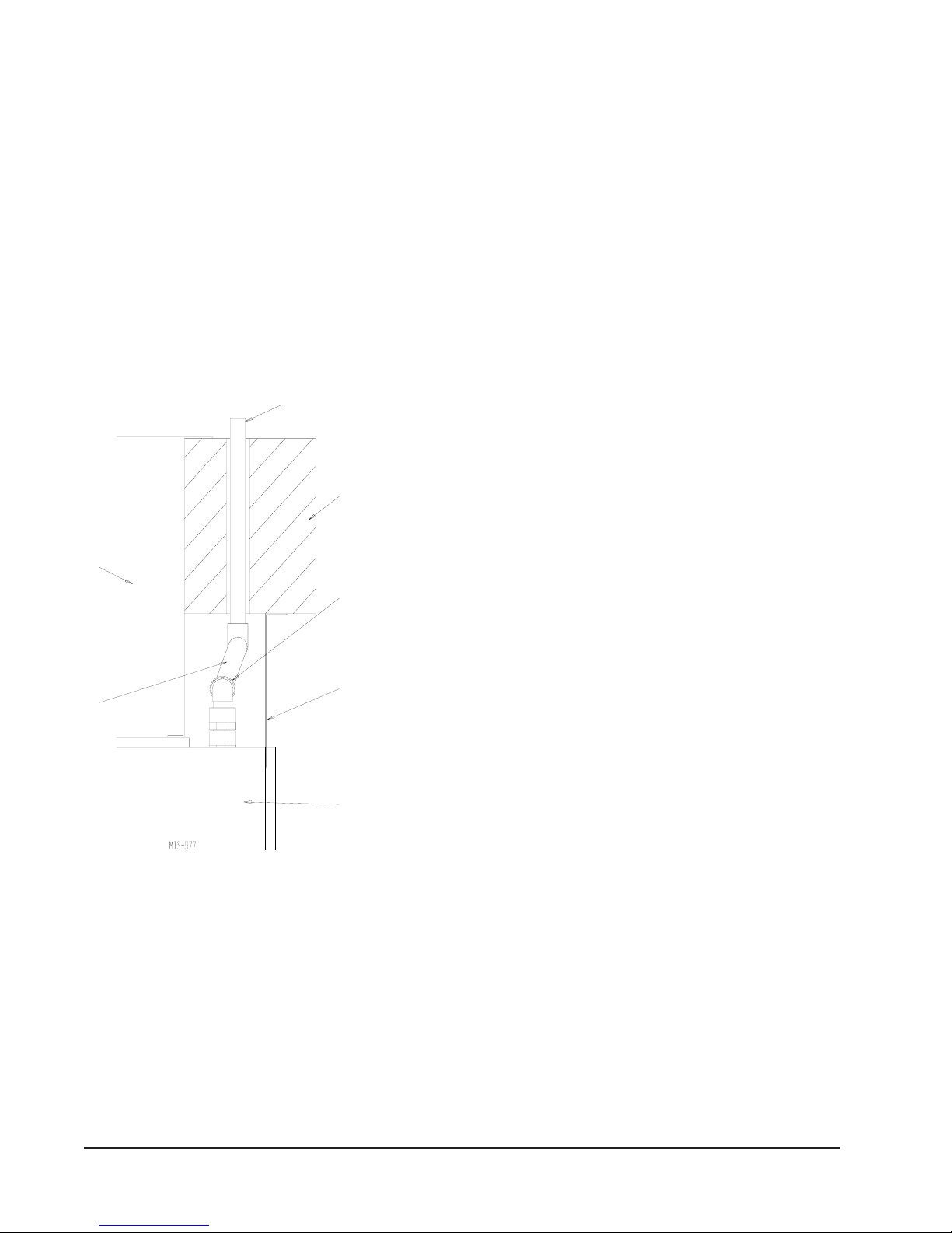
The rear drain can be used with wall thickness of up to
10 inches where a water trap can be installed between
the unit and the interior wall. See Figure 8B. The trap
cannot extend beyond the edge of the unit or it will
interfere with the wall mounting bracket. The drain can
be routed through the floor or through the wall. If the
drain is routed through the wall, the drain line must be
positioned such that it will not interfere with the sleeve
flange or the grille. See Figure 8C. If the drain is to be
routed through an unconditioned space, it must be
protected from freezing.
FIGURE 8C
REAR DRAIN (TOP VIEW)
DRAIN LINE
WALL
(MAXIMUM
10" FOR
REAR DRAIN)
SLEEVE
WATER
TRAP
COUPLINGS NOT
SHOWN BUT
RECOMMENDED
FOR EASE OF
REMOVABILITY
FOR SERVICE
WALL
BRACKET
MIST ELIMINATOR SERVICE (Optional –
only used with one of the vent options)
A mist eliminator is supplied with the wall sleeve. The
mist eliminator is constructed of aluminum frame and
mesh. The mist eliminator is located in the top section
of the wall sleeve and can be removed from the inside of
the building without removing the unit from the wall.
This requires that the ventilation package must be
removed.
The steps necessary to remove each of the vent options
are listed following.
It is recommended that the mist eliminator be inspected
annually and serviced as required. The mist eliminator
can be inspected from the outside of the building by
looking through the outdoor grille. The mist eliminator
can be serviced from the outside. The outdoor grille
must be removed to do so.
The mist eliminator can be cleaned by washing with
soap and water. The excess water should be shaken off
the mist eliminator before it is reinstalled.
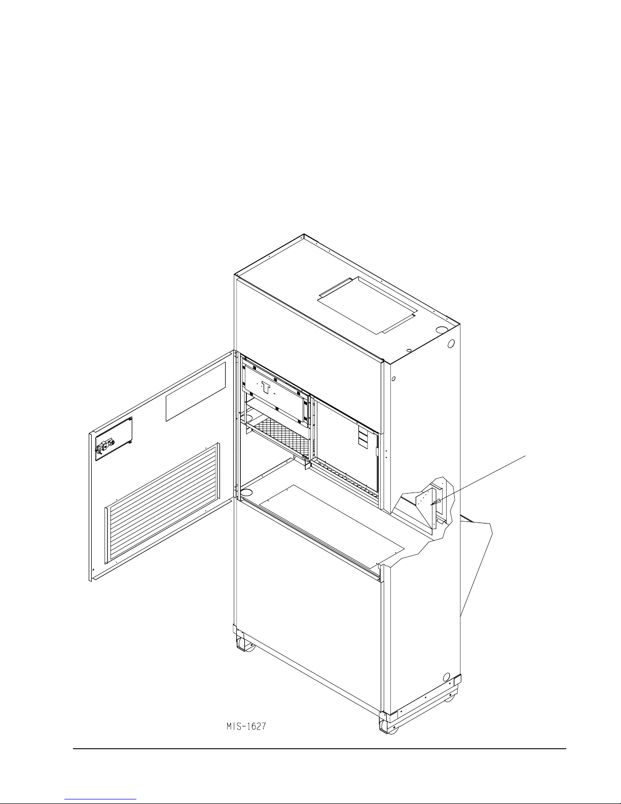
BAROMETRIC FRESH AIR DAMPER (Optional)
Before starting to remove make sure the power has been
turned off. The hinged return air grille panel must be
opened. The fresh air damper assembly can be seen on
the back of the unit. Refer to Figure 9.
1. The fresh air damper is attached to the back of the
unit with one screw on either side of the assembly.
Both of the screws must be removed.
2. Once the mounting screws are removed, tilt the
assembly down and lift it out.
The mist eliminator can be seen through the opening.
The mist eliminator must be raised up and the bottom
can be pulled toward the front of the unit.
UNIT
Manual 2100-418F
Page 13 of 49
COMMERCIAL ROOM VENTILATOR OPTION
Before starting the removal make sure the power has
been turned off. The hinged return air grille must be
opened. The commercial room ventilator (CRV) can be
seen after the panel has been removed. The CRV must
be removed to gain access to the mist eliminator.
1. The two mounting screws in the front of the CRV
must be removed.
FRESH AIR DAMPER REMOVAL
2. The power connectors for the CRV (located on the
right side of the unit) must be disconnected.
Squeeze the tabs on the sides of the connector and
pull straight out. Unplug both of the connectors.
3. Slide the CRV straight out of the unit.
The mist eliminator can be seen through the opening in
the back of the unit. The mist eliminator must be raised
up and the bottom can be pulled toward the front of the
unit and removed.
FIGURE 9
MOUNTING SCREW
Manual 2100-418F
Page 14 of 49
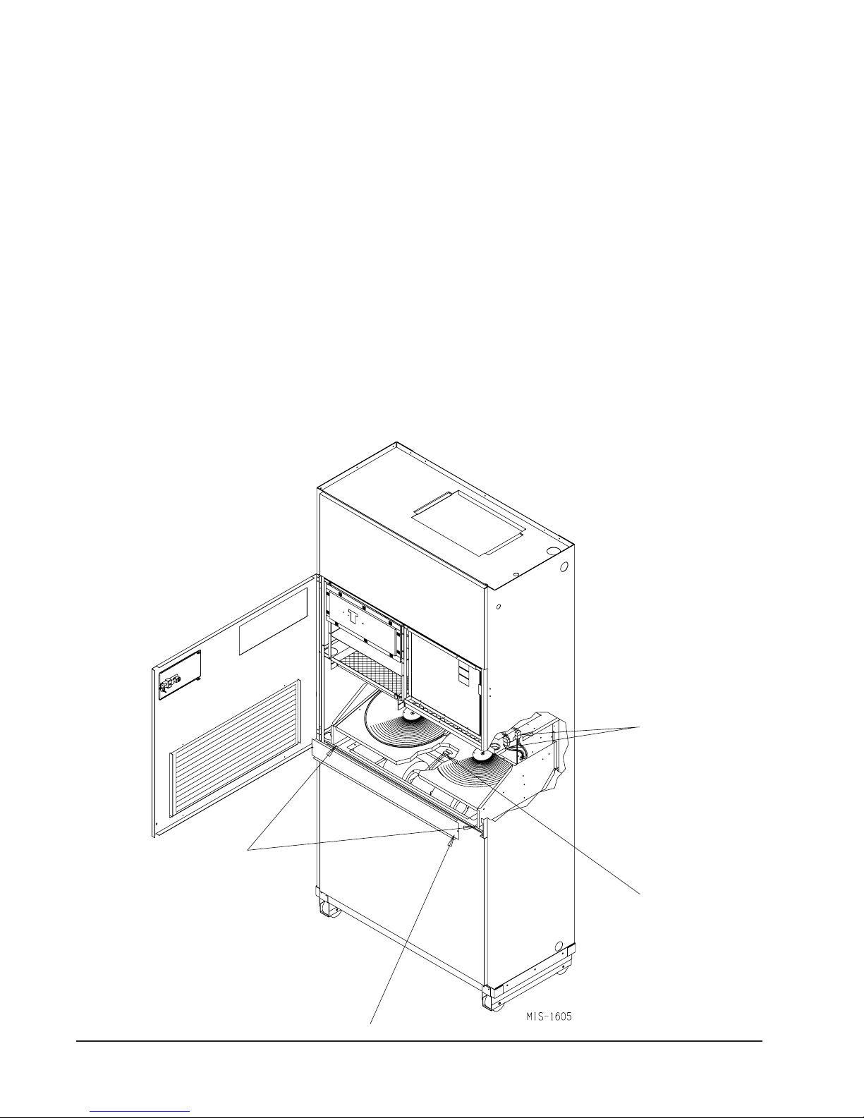
QTEC ENERGY RECOVERY VENTILATOR
OPTION
Before starting the removal make sure that the power
has been turned off. The hinged return air grille panel
must be opened. The energy recovery ventilator
(QERV) can be seen after the panel is opened. To gain
access to the mist eliminator, the QERV must be
removed. Refer to Figure 10
1. The front fill plate of the QERV must be removed.
There is one screw on either side of the plate.
Remove these screws and remove the plate.
2. On either side of the QERV there are mounting
screws that hold the QERV in place. Remove both
of these screws.
REMOVAL OF THE QTEC ENERGY RECOVERY VENTILATOR
3. Underneath the heat recovery cassette there is a
power connector for the lower blower assembly. To
disconnect this plug, the tabs on both sides of the
plug must be squeezed to release the plug. While
squeezing the tabs, pull the plug out of the socket.
4. The QERV is plugged into the unit on the right side
of the unit. Both of these plugs must be
disconnected to remove the QERV. Squeeze the
tabs on the sides of the connector and pull straight
out.
5. Slide the QERV assembly straight out of the unit
being careful not to let the cassette slide out of the
QERV.
The mist eliminator can be seen through the opening in
the back of the unit. The mist eliminator must be raised
up and the bottom can be pulled toward the front of the
unit and removed.
FIGURE 10
MOUNTING
SCREWS
POWER
CONNECTORS
LOWER BLOWER
ASSEMBLY POWER
CONNECTOR
FRONT FILL
Manual 2100-418F
Page 15 of 49
 Loading...