

Bard QH242, QH362, QH422, QH482, QH602 Installation Instructions Manual
...
INSTALLATION
INSTRUCTIONS
QTEC SERIES
PACKAGED HEAT PUMP
Models:
QH242 QH302
QH362 QH422
QH482 QH602
Bard Manufacturing Company
Bryan, Ohio 43506
Since 1914 . . . Moving ahead, just as planned.
MIS-1554
Manual: 2100-379
Supersedes:
File: Vol II Tab 14
Date: 12-01-00
© Copyright 2000

CONTENTS
Getting Other Information and Publications
For more information, contact these publishers:..........1
EC General Information
QT
QT
EC Model Nomenclature .......................................... 2
Shipping Damage.........................................................6
Unit Removal From Skid .............................................. 6
Handling Unit After Removal From Skid ...................... 7
General.........................................................................7
Minimum Installation Height ......................................... 7
Duct Work .................................................................... 9
Filters............................................................................9
Fresh Air Intake .......................................................... 10
Condensate Drain ...................................................... 10
Service Light............................................................... 11
Installation Instructions
Mounting the Unit .......................................................12
Wiring — Main Power.................................................13
Wiring — Low Voltage Wiring ....................................13
Start Up
Description of Standard Equipment ............................... 18
Optional CFM (QH361QH421and QH481 Only)............18
Important Installer Note ................................................. 18
Phase Monitor................................................................ 18
Three Phase Scroll Compressor Start Up
Information ................................................................ 18
Service Hints..................................................................19
Mist Eliminator Service .................................................. 19
Vent Options ..................................................................20
Sequence of Operation.................................................. 23
Optional Climate Controls Sequence
of Operation ..............................................................23
Pressure Service Ports .................................................. 23
Defrost Cycle ................................................................. 24
Troubleshooting
Solid State Heat Pump Control Troubleshooting
Procedure ...................................................................... 26
Checking Temperature Sensor ...................................... 2 6
Fan Blade Setting Dimensions ...................................... 27
Refrigerant Charge ........................................................ 27
Pressure Charts ......................................................28 - 29
Optional Accessories ..................................................... 3 0
Figures
Figure 1 Unit Dimensions .......................................... 5
Figure 2 Air Seal on Bottom of Unit ...........................6
Figure 3 Removal of Unit From Skid ......................... 6
Figure 4 Unit on Appliance Cart for Moving...............7
Figure 5 Installation With Free Blow Plenum ............ 8
Figure 6 Ducted Application ...................................... 8
Figure 7 Supply Duct Connections ............................ 9
Figure 8 Filter Location .............................................. 9
Figure 9 Side Drain..................................................10
Figure 10 Optional Rear Drain...................................10
Figure 11 Rear Drain (Top View) ............................... 11
Figure 12 Unit Mounting ............................................ 11
Figure 13 Screws in Wheels of Unit .......................... 12
Figure 14 Component Location ................................. 1 3
Figure 15 Thermostat Plug Terminals ........................ 14
Figure 16 Thermostat Wiring Diagram "X" Option....15
Figure 17 Thermostat Wiring Diagram "A" Option....16
Figure 18 Thermostat Wiring Diagram "D" Option ... 17
Figure 19 Fresh Air Damper Removal ....................... 21
Figure 20 QERV Removal ......................................... 22
Figure 24 Heat Pump Control Board ......................... 27
Figure 24 Fan Blade Setting ...................................... 30
Tables
Table 1 Factory Built-In Electric Heat Table .............. 2
Table 2 Electrical Specifications................................3
Table 2A Electrical Specifications................................4
Table 3 Operating Voltage Range ...........................13
Table 4 Wall Thermostats and Subbase
Combinations..............................................14
Table 5 Troubleshooting .......................................... 25
Table 6 Temperature vs Resistance of
Temperature Sensor ................................... 26
Table 7 Fan Blade Dimensions ............................... 27
Table 8 Suction Line Temperatures ......................... 27
Table 9 Indoor Blower Performance........................ 27
Table 10 Cooling Pressure ........................................28
Table 11 Heating Pressure ........................................ 2 9
Table 12 Optional Accessories .................................. 30
i

GETTING OTHER INFORMATION AND PUBLICATIONS
These publications can help you install the air
conditioner or heat pump. You can usually find these at
your local library or purchase them directly from the
publisher. Be sure to consult current edition of each
standard.
National Electrical Code ..................... ANSI/NFPA 70
Standard for the Installation ............. ANSI/NFPA 90A
of Air Conditioning and
Ventilating Systems
Standard for Warm Air..................... ANSI/NFPA 90B
Heating and Air
Conditioning Systems
Load Calculation for...................... ACCA Manual J or
Winter and Summer Manual N
Air Conditioning
Low Pressure, Low Velocity ........ ACCA Manual D or
Duct System Design Manual Q
Winter and Summer
Air Conditioning
FOR MORE INFORMATION, CONTACT
THESE PUBLISHERS:
ACCA Air Conditioning Contractors of America
1712 New Hampshire Avenue
Washington, DC 20009
Telephone: (202) 483-9370
Fax: (202) 234-4721
ANSI American National Standards Institute
11 West Street, 13th Floor
New York, NY 10036
Telephone: (212) 642-4900
Fax: (212) 302-1286
ASHRAE American Society of Heating, Refrigeration,
and Air Conditioning Engineers, Inc.
1791 Tullie Circle, N.E.
Atlanta, GA 30329-2305
Telephone: (404) 636-8400
Fax: (404) 321-5478
NFPA National Fire Protection Association
Batterymarch Park
P.O. Box 9101
Quincy, MA 02269-9901
Telephone: (800) 344-3555
Fax: (617) 984-7057
Manual 2100-379
Page 1
QT
EC
Series General Information
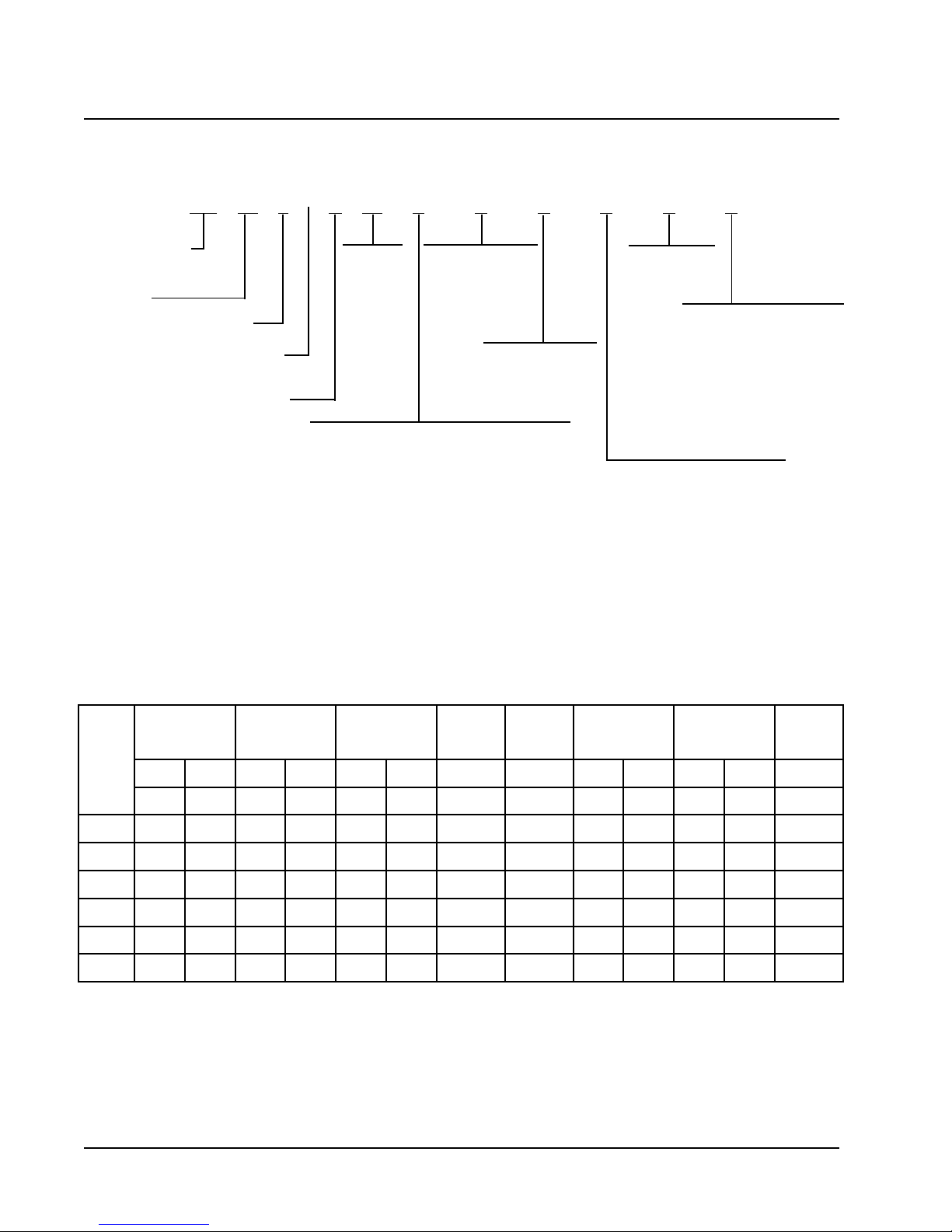
QTEC MODEL NOMENCLATURE
QH 36 2 – A 10 X X X X X X
MODEL NUMBER |
QH - QTEC Model
CAPACITY |
24 - 2 Ton
30 - 2-1/2 Ton
36 - 3 Ton
42 - 3-1/2 Ton
48 - 4 Ton
60 - 5 Ton
sledoM
1-V0421-V8021-V0421-V8021-V0421-V8023-V0843-V0841-V0421-V8021-V0421-V8023-V084
FILTER OPTIONS
X - 1 Inch Fiberglass
(Standard)
F - 2 Inch Fiberglass
P - 2 Inch Pleated
REVISION |
SPECIAL UNITS |
L - Low Ampacity Circuit
VOLTS & PHASE |
A - 230/208/60/1
B - 230/208/60/3
C - 460/60/3
KW
0Z- 0KW
05 -5KW
06 -6KW
09 -9KW
10 -10KW
12 -12KW
15 -15KW
VENTILATION OPTIONS
X - Barometric Fresh Air Damper (Standard)
B - Blank-off Plate
V - Commercial Ventilator - Motorized w/Exhaust
Spring Return
P - Commercial Ventilator - Motorized w/Exhaust
Power Return
E - Economizer - Fully Modulating w/Exhaust
R - Energy Recovery Ventilator w/Exhaust
TABLE 1
FACTORY BUILT-IN ELECTRIC HEAT TABLE
A-242HQ
A-203HQB-242HQB-203HQC-242HQC-203HQ
COLOR OPTIONS
V - Platinum w/Slate
Front (Vinyl)
4 - Gray paint
COIL OPTIONS
X - Standard
I
NTERNAL CONTROLS
X - Standard
• High Pressure Switch
• Low Pressure Switch
• Compressor Time Delay
E - Low Ambient Control
Q - Outdoor Thermostat
R - Low Ambient Control &
Outdoor Thermostat
CLIMATE CONTROL OPTIONS
X - None
A - Electronic/Non Prog/Man C/O
D - Electronic/Prog/Man/Auto
A-263HQ
A-224HQ
A-284HQ
B-263HQ
B-224HQ
B-284HQ
C-263HQ
C-224HQ
C-284HQ
WKHUTBHUTBHUTBHUTBHUTBHUTBHUTBHUTBHUTBHUTBHUTBHUTBHUTB
0.5083,61092,21 083,61092,21
0.6005,02063,51005,02063,51005,02005,02005,02063,51005,02
0.9007,03000,32007,03000,32007,03007,03007,03000,32007,03
0.01076,23075,42 076,23075,42
0.21000,14007,03000,14
0.51 051,94068,63051,94068,63051,94
Manual 2100-379
Page 2

TABLE 2
ELECTRICAL SPECIFICATIONS
TIUCRICELGNISTIUCRICLAUD
$
%
%
!
.ON
DETAR
SLEDOM
Z0A-242HQ
50A01A-
Z0B-242HQ
60B90B-
Z0C-242HQ
60C90C-
Z0A-203HQ
50A01A-
Z0B-203HQ
60B90B21B-
Z0C-203HQ
60C90C21C-
Z0A-263HQ
50A01A-
-
51A
Z0B-263HQ
60B90B-
-
51B
Z0C-263HQ
60C90C-
-
51C
&STLOV
SESAHP
1-802/032
3-802/032
3-064
1-802/032
3-802/032
3-064
3-802/032
3-802/032
3-064
DLEIF
REWOP
STIUCRIC
1
1
2RO1
1
1
1
1
1
1
1
1
2RO1
1
1
1
1
1
1
1
1
1
1
2RO1
2RO1
1
1
1
1
1
1
1
1
MUMINIM
TIUCRIC
22
74
27
71
53
44
8
71
22
42
94
47
81
63
54
45
9
81
32
72
92
45
97
28
32
14
05
25
11
02
42
62
"
YTICAPMA
03
05
08
02
53
54
51
02
52
53
05
08
52
04
54
06
51
02
52
03
54
06
09
09
03
54
05
06
51
02
03
03
#
MUMIXAM
LANRETXE
ROESUF
TIUCRIC
REKAERB
EZIS
01
8
4
21
8
8
41
21
01
8
8
4
01
8
6
6
41
21
01
8
8
6
4
4
01
8
8
6
41
01
01
01
#
DLEIF
REWOP
ERIW
ERIW
EZIS
01
01
8
21
01
01
41
21
01
01
01
8
01
01
01
01
41
21
01
01
01
01
8
8
01
01
01
01
41
01
01
01
!
MUMINIM
TIUCRIC
DNUORG
YTICAPMA
TKC
A
B
--
--
--
--
22
05
--
--
--
--
--
--
--
--
--
--
--
--
--
--
--
--
42
05
--
--
--
--
--
--
--
--
--
--
--
--
--
--
--
--
--
--
--
--
92
05
23
05
--
--
--
--
--
--
--
--
--
--
--
--
--
--
--
--
"
MUMIXAM
ROESUF
TIUCRIC
TKC
TKC
A
B
--
--
--
--
03
05
--
--
--
--
--
--
--
--
--
--
--
--
--
--
--
--
03
05
--
--
--
--
--
--
--
--
--
--
--
--
--
--
--
--
--
--
--
--
04
05
04
05
--
--
--
--
--
--
--
--
--
--
--
--
--
--
--
--
#
LANRETXE
REKAERB
TKC
DLEIF
REWOP
TKC
A
B
--
--
--
--
01
8
--
--
--
--
--
--
--
--
--
--
--
--
--
--
--
--
01
8
--
--
--
--
--
--
--
--
--
--
--
--
--
--
--
--
--
--
--
--
8
8
8
8
--
--
--
--
--
--
--
--
--
--
--
--
--
--
--
--
#
DNUORG
EZISERIW
TKC
EZISERIW
TKC
TKC
A
B
--
--
--
--
01
01
--
--
--
--
--
--
--
--
--
--
--
--
--
--
--
--
01
01
--
--
--
--
--
--
--
--
--
--
--
--
--
--
--
--
--
--
--
--
01
01
01
01
--
--
--
--
--
--
--
--
--
--
--
--
--
--
--
--
Maximum size of the time delay fuse or HACR type circuit breaker for protection of field wiring conductors.
Q
Based on 75° C copper wire. All wiring must conform to the National Electrical Code and all local codes.
R
These “Minimum Circuit Ampacity” values are to be used for sizing the field power conductors. Refer to the National Electric Code
S
(latest revision), article 310 for power conductor sizing. CAUTION: When more than one field power conductor circuit is run
through one conduit, the conductors must be derated. Pay special attention to Note 8 of T able 310 regarding Ampacity
Adjustment Factors when more than three conductors are in a raceway.
Maximum KW that can operate with heat pump on is 10KW. Other 5KW energizes during emergency heating only.
T
Maximum KW that can operate with heat pump on is 9KW. Other 6KW energizes during emergency heating only.
U
ELECTRICAL SPECIFICATIONS Continued on Page 4 TABLE 2A
Manual 2100-379
Page 3

%
$
%
%
$
%
TABLE 2A
ELECTRICAL SPECIFICATIONS
(continued from Page 3)
TIUCRICELGNISTIUCRICLAUD
!
.ON
DETAR
LEDOM
Z0A-224HQ
50A01A-
-
51A
Z0B-224HQ
60B90B-
-
51B
Z0C-224HQ
60C90C-
-
51C
Z0A-284HQ
50A01A-
-
51A
Z0B-284HQ
50B01B-
-
51B
Z0C-284HQ
60C90C-
-
51C
Z0A-206HQ
Z0B-206HQ
Z0C-206HQ
&STLOV
ESAHP
1-802/032
3-802/032
3-064
1-802/032
3-802/032
3-064
1-802/03215406801---------------3-802/03231354801----------------
3-064302522121----------------
DLEIF
REWOP
STIUCRIC
1
1
2RO1
2RO1
1
1
1
1
1
1
1
1
1
1
2RO1
2RO1
1
1
1
1
1
1
1
1
MUMINIM
TIUCRIC
33
85
38
38
42
34
25
25
61
52
03
03
63
16
68
68
62
44
35
35
41
32
72
72
"
YTICAPMA
05
06
09
09
03
54
05
06
02
52
03
03
06
07
001
001
04
05
06
06
51
52
03
03
#
MUMIXAM
LANRETXE
ROESUF
TIUCRIC
REKAERB
ERIW
EZIS
8
6
4
4
01
8
6
6
21
01
01
01
8
6
3
3
8
8
6
6
41
01
01
01
#
DLEIF
REWOP
ERIW
EZIS
01
01
8
8
01
01
01
01
21
01
01
01
01
8
6
6
01
01
01
01
41
01
01
01
!
MUMINIM
DNUORG
TIUCRIC
YTICAPMA
TKC
A
B
--
--
--
--
33
05
33
05
--
--
--
--
--
--
--
--
--
--
--
--
--
--
--
--
--
--
63
52
63
05
63
05
--
--
--
--
--
--
--
--
--
--
--
--
--
--
--
--
"
MUMIXAM
ROESUF
TIUCRIC
REKAERB
TKC
TKC
A
B
--
--
--
--
04
05
04
05
--
--
--
--
--
--
--
--
--
--
--
--
--
--
--
--
--
--
06
52
06
05
06
05
--
--
--
--
--
--
--
--
--
--
--
--
--
--
--
--
#
LANRETXE
TKC
DLEIF
REWOP
EZISERIW
TKC
A
B
--
--
--
--
8
8
8
8
--
--
--
--
--
--
--
--
--
--
--
--
--
--
--
--
--
--
8
01
8
8
8
8
--
--
--
--
--
--
--
--
--
--
--
--
--
--
--
--
#
DNUORG
EZISERIW
TKC
TKC
A
TKC
B
--
--
--
--
01
01
01
01
--
--
--
--
--
--
--
--
--
--
--
--
--
--
--
--
--
--
01
01
01
01
01
01
--
--
--
--
--
--
--
--
--
--
--
--
--
--
--
--
Maximum size of the time delay fuse or HACR type circuit breaker for protection of field wiring conductors.
Q
R
Based on 75° C copper wire. All wiring must conform to the National Electrical Code and all local codes.
These “Minimum Circuit Ampacity” values are to be used for sizing the field power conductors. Refer to the National Electric
S
Code (latest revision), article 310 for power conductor sizing. CAUTION: When more than one field power conductor
circuit is run through one conduit, the conductors must be derated. Pay special attention to Note 8 of Table 310 regarding
Ampacity Adjustment Factors when more than three conductors are in a raceway.
Maximum KW that can operate with heat pump on is 10KW. Other 5KW energizes during emergency heating only.
T
Maximum KW that can operate with heat pump on is 9KW. Other 6KW energizes during emergency heating only.
U
Manual 2100-379
Page 4
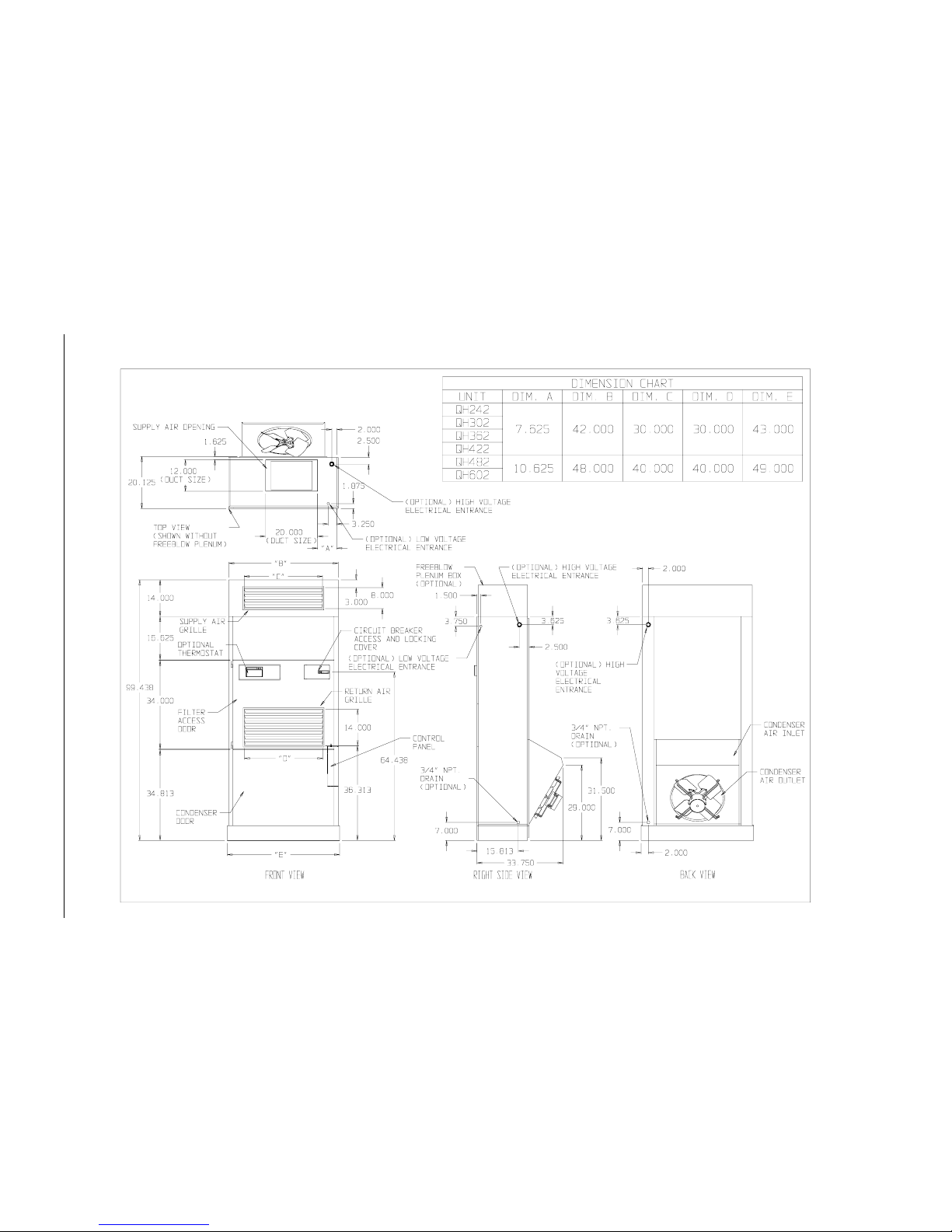
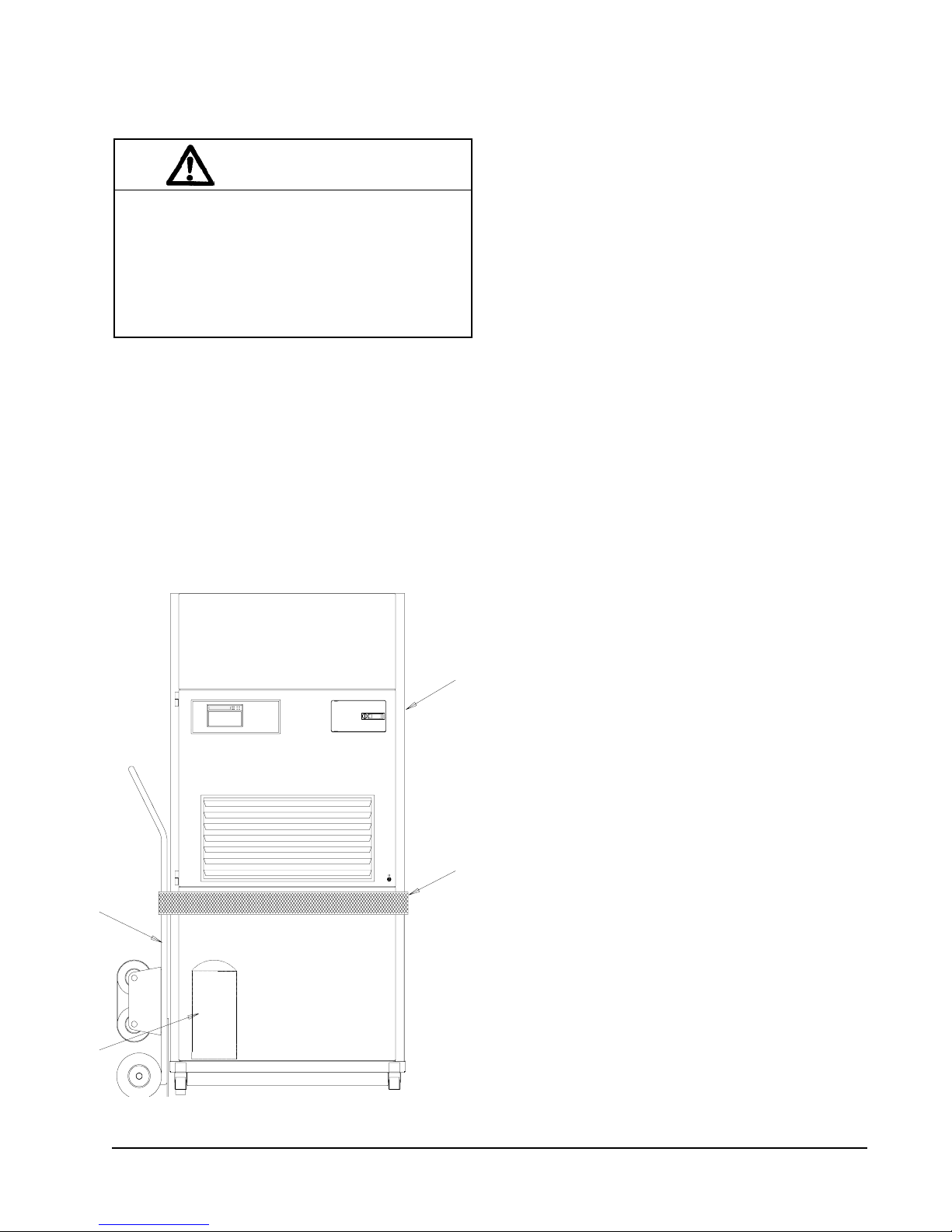
Manual 2100-379
Page 5
FIGURE 1
UNIT DIMENSIONS
MIS-1572
SHIPPING DAMAGE
Upon receipt of equipment, the carton should be
checked for external signs of shipping damage. The
skid must remain attached to the unit until the unit is
ready for installation. If damage is found, the receiving
party must contact the last carrier immediately,
preferably in writing, requesting inspection by the
carrier’s agent.
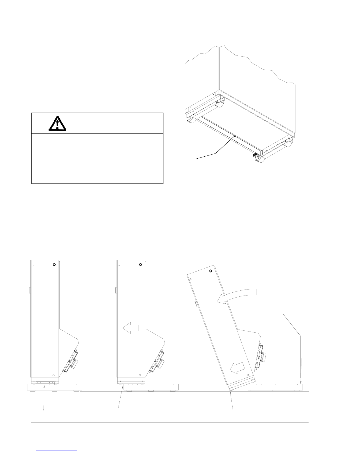
UNIT REMOVAL FROM SKID
WARNING
This unit is heavy and requires more than one
person to handle and remove from the skid.
Check unit wheels to ensure that wheels are
locked before removing from skid. Extreme
caution must be taken to prevent injury to
personnel and damage to the unit.
It is recommended that the unit not be removed from
the skid with a fork lift since the air seal under the unit
could be damaged. See Figure 2.
The shipping brackets on each side of the unit must be
removed and discarded. See Figure 3-A. The return air
grille panel can be removed to provide a place to hold
FIGURE 2
AIR SEAL UNDER QT
Air Seal
the unit. The unit can be slid forward on the skit until
the front wheels hang over the edge of the skid. See
Figure 3-B. The unit can be tipped forward and slid
down the edge of the skid until the front wheels touch
the ground. See Figure 3-C. The wheels will not roll.
They are shipped from the factory locked so they will
not roll. The back of the skid will have to be held down
to keep it from tipping up. The skid can be slid out
from under the unit. The unit can then be set upright.
EC
UNIT
MIS-1008
FIGURE 3
REMOVAL OF UNIT FROM SKID
Hold Skid Down
A Shipping Brackets B Front Wheels Over Edge C Front Wheels On Floor
Manual 2100-379
Page 6
MIS-1007
HANDLING UNIT AFTER REMOVAL
FROM SKID
WARNING
Exercise extreme caution when pushing the
unit on the rollers. Handle and push from the
lower 1/3 of the unit. Insure that debris is not
on the floor where the unit is to be moved on
the rollers. Failure to do so could result in the
unit tipping over and causing bodily injury and/
or damage to the unit.
The unit will have to be turned sideways and removed
from the skid to fit through a 36” doorway. If the door
height allows, the unit can be slid sideways through the
door.
If the unit can not be slid through the door, then the unit
will have to be put on a cart and tipped down to roll
through the door. It is recommended that an appliance
cart by used with a strap to hold the unit on the cart.
The wheels of the unit must be locked. If the wheels
were allowed to roll, the unit could roll off the cart.
The unit should always be carted from the left side.
This is the side where the compressor is located. See
Figure 4. The blade of the appliance cart should be slid
under the wheels of the unit. The strap of the appliance
cart should be placed around the unit and strapped
tightly. Help will be required to tip the unit back onto
the cart. The unit can be leaned far enough back to be
rolled through the door. Be careful when setting the
unit back up to keep from damaging the unit.
GENERAL
The equipment covered in this manual is to be installed
by trained, experienced service and installation
technicians.
The unit is designed for use with or without duct work.
For use without duct work, Plenum Box QPB42 is
recommended.
These instructions explain the recommended method to
install the air cooled self-contained unit and the
electrical wiring connections to the unit.
APPLIANCE
CART
FIGURE 4
UNIT ON APPLIANCE CART
QTEC UNIT
(Right Side)
STRAP
These instructions and any instructions packaged with
any separate equipment required to make up the entire
air conditioning system should be carefully read before
beginning the installation. Note particularly “Start
Procedure” and any tags and/or labels attached to the
equipment.
While these instructions are intended as a general
recommended guide, they do not supersede any
national and/or local codes in any way. Authorities
having jurisdiction should be consulted before the
installation is made. See Page 1 for information on
codes and standards.
Size of unit for a proposed installation should be based
on heat loss calculation made according to methods of
Air Conditioning Contractors of America (ACCA).
The air duct should be installed in accordance with the
Standards of the National Fire Protection Systems of
Other Than Residence Type, NFPA No. 90A, and
Residence Type Warm Air Heating and Air
Conditioning Systems, NFPA No. 90B. Where local
regulations are at a variance with instructions, installer
should adhere to local codes.
COMPRESSOR
MIS-1555
MINIMUM INSTALLATION HEIGHT
The minimum installation height of the unit with a Free
Blow Plenum is 8 ft. 6 in. This provides enough
clearance for the plenum to be removed. See Figure 5.
The minimum installation height for ducted
applications is 8 ft. 4-1/2 in. This provides enough
clearance to install the duct work. See Figure 6.
Manual 2100-379
Page 7
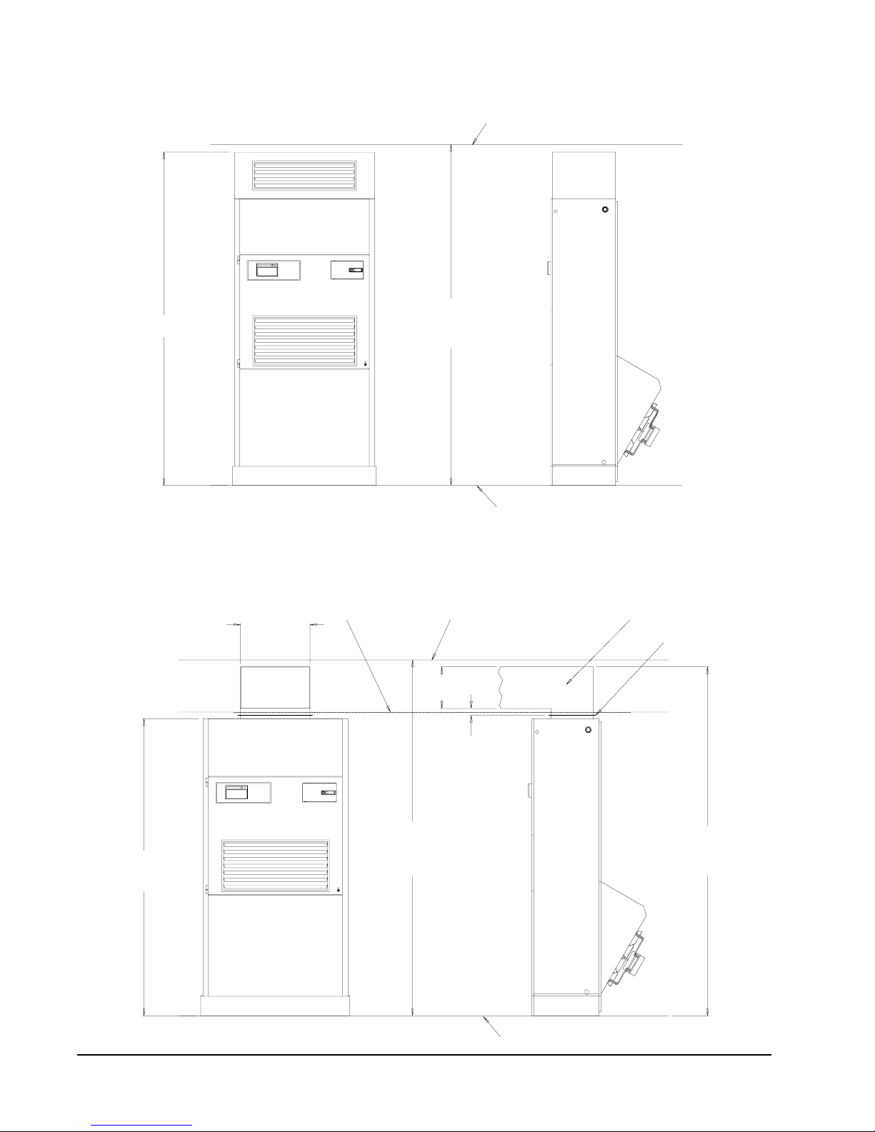
FIGURE 5
INSTALLATION WITH FREE BLOW PLENUM
CEILING
8 FT. - 4 IN.
20 IN.
MINIMUM
MINIMUM RECOMMENDED
8 FT. - 6 IN.
CEILING HEIGHT
FIGURE 6
DUCTED APPLICATION
SUSPENDED
CEILING
FIXED CEILING
12 IN.
MINIMUM
FLOOR
MIS-1574
DUCT
DUCT FLANGE
7 FT. - 2 IN.
UNIT HEIGHT
Manual 2100-379
Page 8
2 IN. MINIMUM
FROM DUCT FLANGE
TO DUCT BOTTOM
8 FT. - 7 IN.
MINIMUM RECOMMENDED
CEILING HEIGHT
FLOOR
8 FT. - 4.5 IN.
MINIMUM REQUIRED
INSTALLATION HEIGHT
MIS-1573
 Loading...