

Page 1

OPERATION INSTRUCTIONS
ENERGY RECOVERY VENTILATOR
WITH EXHAUST
Model:
QERV-A4B
QERV2-A4B
For Use With Bard
2 Through 5 Ton
QH Series Heat Pumps
BARD MANUFACTURING COMPANY
Bryan, Ohio 43506
Since 1914...Moving ahead, just as planned.
Manual: 2100-310D
Supersedes: 2100-310C
File: Volume II, Tab 14
Date: 01-10-05
Page 2

CONTENTS
QERV Model Nomenclature ................................... 1
Electrical Specifications.......................................... 1
General Description of QERV ................................ 1
Control Requirements ............................................ 1
Recommended Control Sequences ....................... 2
Ventilation Air Flow ................................................. 2
Performance and Application Data .................... 3 - 4
Energy Recovery Ventilator Maintenance .............. 4
Maintenance Procedures ....................................... 5
Figures
Figure 1 Belt Replacement Instructions ................. 6
Figure 2 Hub Assembly with Ball Bearings ............ 7
Tables
Table 1 Ventilation Air (CFM)................................ 2
Table 2 Summer Cooling Performance ................ 3
Table 3 Winter Heating Performance ................... 4
COPYRIGHT DECEMBER 2003
BARD MANUFACTURING COMPANY
BRYAN, OHIO USA 43506
Page 3
MODEL NOMENCLATURE
Q ERV - A 4 B
Q - QH Series
Energy Recovery Ventilator
Electrical
A - 230/208 volt
QH Series Cabinet Size
4 - QH241, 301, 361, 421,
481, 601
Modification Code
ELECTRICAL SPECIFICATIONS
ledoMegatloVspmA
VREQ802/0322.2V42
GENERAL DESCRIPTION
The Energy Recovery Ventilator was designed to
provide energy efficient, cost effective ventilation to
meet I. A. Q. (Indoor Air Quality) requirements while
still maintaining good indoor comfort and humidity
control for a variety of applications such as schools,
classrooms, lounges, conference rooms, beauty salons
and others. It provides a constant supply of fresh air
for control of airborne pollutants including CO2,
smoke radon, formaldehyde, excess moisture, virus
and bacteria.
The ventilator incorporates patented rotary heat
exchange state-of-the-art technology to remove both
heat and moisture.
It is designed as a single package which is factory
installed. The package consists of a unique rotary
Energy Recovery Cassette that can be easily removed
for cleaning or maintenance. It has two 15 inch
diameter heat transfer wheels for efficient heat
transfer. The heat transfer wheels use a permanently
bonded dry desiccant coating for total heat recovery.
htiWesUroF
ledoM
VREQ
lortnoC
egatloV
CONTROL REQUIREMENTS
B-,A-42HQ
B-,A-03HQ
B-,A-63HQ
B-,A-24HQ
B-,A-84HQ
B-,A-06HQ
C-42HQ
C-03HQ
C-63HQ
C-24HQ
C-84HQ
C-06HQ
stinUgniwolloFlacirtcelE
802/032
esahP3ro1
064
esahP3
1. Indoor blower motor must be run when ever the
QERV is run.
2. Select the correct motor speed on the QERV.
Using Table 1 of the QERV Installation Instructions
determine the motor speed needed to get the desired
amount of ventilation air needed. For instance, do
not use the high speed tap on a QERV if only 200
CFM of ventilation air is needed. Use the low
speed tap. Using the high speed tap would serve no
useful purpose and would effect the overall
efficiency of the air conditioning system. System
operation costs would also increase.
3. Run the QERV only during periods when the
conditioned space is occupied. Running the QERV
during unoccupied periods wastes energy, decreases
the expected life of the QERV, and can result in a
large moisture buildup in the structure. The QERV
removes 60 to 70% of the moisture in the incoming
air, not 100% of it. Running the QERV when the
structure is unoccupied allows moisture to build up
in the structure because there is little or no cooling
load. Thus, the air conditioner is not running
enough to remove the excess moisture being
brought in. Use a control system that in some way
can control the system based on occupancy.
Ventilation is accomplished with 2 blower/motor
assemblies each consisting of a drive motor and dual
blowers for maximum ventilation at low sound levels.
Air is exhausted at the same rate that fresh air is
brought into the structure thus not pressuring the
building. The rotating energy wheels provide the heat
transfer effectively during both summer and winter
conditions. Provides required ventilation to meet the
requirements of ASHRAE 62-2001 standard.
NOTE: Operation is not recommended below 5°F
outdoor temperature because freezing of
moisture in the heat transfer wheel can occur.
IMPORTANT
Operating the QERV during unoccupied
periods can result in a build up of moisture in
the classroom.
Manual 2100-310D
Page 1
Page 4
RECOMMENDED CONTROL
SEQUENCES
Several possible control scenarios are listed below:
1. Use a programmable electronic thermostat with
auxiliary terminal to control the QERV based on
daily programmed occupancy periods. Bard
markets and recommends the White-Rodgers
1F94-80 (Bard Part No. 8403-034), programmable
electronic thermostat for heat pump applications.
2. Use a motion sensor in conjunction with a
mechanical thermostat to determine occupancy in
the classroom. Bard markets the CS2000 for this
use.
3. Use a DDC control system to control the QERV
based on a room occupancy schedule to control the
QERV.
4. Tie the operation of the QERV into the light
switch. The lights in a room are usually on only
when occupied.
5. Use a manual timer that the occupants turn to
energize the QERV for a specific number of hours.
6. Use a programmable mechanical timer to energize
the QERV and indoor blower during occupied
periods of the day.
VENTILATION AIR FLOW
The QERV is equipped with a 3 speed motor to
provide the capability of adjusting the ventilation rates
to the requirements of the specific application by
simply changing motor speeds.
TABLE 1
VENTILATION AIR (CFM)
deepShgiH
kcalB(
MFC
054573003
The units are wired from the factory on low speed.
The speed can be changed by switching the toggle
switch on the front of the QERV to the desired speed.
The QERV2-A4B is equipped with independently
controlled 3-speed motor to provide the capability of
adjusting the ventilation rates to the requirements of
the specific application and to be able to provide
positive pressure in the structure. This is
accomplished by setting the intake blower on a higher
speed than the exhaust blower.
deepSmuidiM
)eulB(
deepSwoL
)deR(
Manual 2100-310D
Page 2
Page 5

PERFORMANCE AND APPLICATION DATA
TABLE 2
SUMMER COOLING PERFORMANCE
(INDOOR DESIGN CONDITIONS 75° DB / 62° WB)
tneibmA
.D.O
BW/BD
FseergeDTLVSLVLLVTRHSRHLRHTLVSLVLLVTRHSRHLRHTLVSLVLLVTRHSRHLRH
57
56412
08541
4886
501
07
08541
08541
0
56
08541
08541
0
08
09513
05121
04491
57
56412
05121
4139
001
07
25321
05121
202
56
05121
05121
0
06
05121
05121
0
08
09513
0279
07812
57
56412
0279
44711
59
07
25321
0279
2362
56
0279
0279
0
06
0279
0279
0
08
09513
0927
00342
57
56412
0927
57141
09
07
25321
0927
2605
56
0927
0927
0
06
0927
0927
0
08
09513
0684
03762
57
56412
0684
50661
58
07
25321
0684
2947
56
0684
0684
0
06
0684
0684
0
57
56412
0342
53091
07
25321
0342
08
570756
56
2524
06
0342
25321
2524
06
0
2299
0342
2281
0342
0
0
25321
0
2524
0
0
MFC054–ETARNOITALITNEV
ycneiciffE%56
25931
7749
5744
78871
05121
7375
7749
7749
0
05121
05121
0
7749
7749
0
05121
05121
0
33502
7987
53621
52362
52101
00261
25931
7987
4506
78871
52101
2677
9208
7987
131
39201
52101
861
7987
7987
0
52101
52101
0
7987
7987
0
52101
52101
0
33502
8136
51241
52362
0018
52281
25931
8136
4367
78871
0018
7879
9208
8136
1171
39201
0018
3912
8136
8136
0
0018
0018
0
8136
8136
0
0018
0018
0
33502
8374
49751
52362
5706
05202
25931
8374
3129
78871
5706
21811
9208
8374
0923
39201
5706
8124
8374
8374
0
5706
5706
0
8374
8374
0
5706
5706
0
33502
9513
47371
52362
0504
57222
25931
9513
39701
78871
0504
73831
9208
9513
0784
39201
0504
3426
9513
9513
0
0504
0504
0
9513
9513
0
0504
0504
0
25931
9751
27321
78871
5202
26851
9208
9751
9446
39201
5202
8628
4672
9751
4811
3453
5202
8151
9751
9751
0
5202
5202
0
9208
0
9208
39201
0
39201
4672
0
4672
3453
0
3453
0
0
0
0
0
0
MFC573–ETARNOITALITNEV
ycneiciffE%66
50811
8108
6873
01341
0279
0954
8108
8108
0
0279
0279
0
8108
8108
0
0279
0279
0
47371
2866
29601
06012
0018
06921
50811
2866
3215
01341
0018
0126
3976
2866
111
5328
0018
531
2866
2866
0
0018
0018
0
2866
2866
0
0018
0018
0
47371
5435
82021
06012
0846
08541
50811
5435
9546
01341
0846
0387
3976
5435
7441
5328
0846
5571
5435
5435
0
0846
0846
0
5435
5435
0
0846
0846
0
47371
9004
56331
06012
0684
00261
50811
9004
6977
01341
0684
0549
3976
9004
4872
5328
0684
5733
9004
9004
0
0684
0684
0
9004
9004
0
0684
0684
0
47371
2762
10741
06012
0423
02871
50811
2762
2319
01341
0423
07011
3976
2762
0214
5328
0423
5994
2762
2762
0
0423
0423
0
2762
2762
0
0423
0423
0
50811
6331
96401
01341
0261
09621
3976
6331
7545
5328
0261
5166
8332
6331
2001
5382
0261
5121
6331
6331
0
0261
0261
0
3976
0
3976
5328
0
5328
8332
0
8332
5382
0
5382
0
0
0
0
0
0
MFC003–ETARNOITALITNEV
ycneiciffE%76
7859
2156
5703
2156
2156
0
2156
2156
0
01141
7245
3868
7859
7245
0614
7155
7245
09
7245
7245
0
7245
7245
0
01141
1434
8679
7859
1434
6425
7155
1434
5711
1434
1434
0
1434
1434
0
01141
6523
45801
7859
6523
1336
7155
6523
1622
6523
6523
0
6523
6523
0
01141
0712
93911
7589
0712
6147
7155
0712
6433
0712
0712
0
0712
0712
0
7859
5801
2058
7155
5801
2344
9981
5801
418
5801
5801
0
7155
0
7155
9981
0
9981
0
0
0
LEGEND
VTL = Ventilation Load – Total HRT = Heat Recovery – Total
VLS = Ventilation Load – Sensible HRS = Heat Recovery – Sensible
VLL = Ventilation Load – Latent HRL = Heat Recovery – Latent
Manual 2100-310D
Page 3
Page 6

TABLE 3
WINTER HEATING PERFORMANCE
(INDOOR DESIGN CONDITIONS 70° F DB)
tneibmA
.D.OETARNOITALITNEV
BD
FseergeD
LVWRHWLVWRHWLVWRHW
56034244915202046102618231
06068488830504082304236562
55092723855706029406845893
05027967770018165608463135
5405121027952101102800182466
04085414661105121148902790797
5301071806315714118411043118929
03044912555100261221310692172601
52078126947152281267410854155911
02003420449105202204610026148231
51037624831257222240810287121641
NOTE: Sensible performance only is shown for
winter application.
.ffE%08MFC054.ffE%18MFC573.ffE208MFC003
LEGEND
WVL = Winter Ventilation Load
WH = Winter Heat Recovery
ENERGY RECOVERY VENTILATOR
MAINTENANCE
GENERAL INFORMATION
The ability to clean exposed surfaces within air
moving systems is an important design consideration
for the maintenance of system performance and air
quality. The need for periodic cleaning will be a
function of operating schedule, climate, and
contaminants in the indoor air being exhausted and in
the outdoor air being supplied to the building. All
components exposed to the airstream, including energy
recovery wheels, may require cleaning in most
applications.
Rotary counterflow heat exchanges (heat wheels) with
laminar airflow are “self-cleaning” with respect to dry
particles. Smaller particles pass through; larger
particles land on the surface and are blow clear as the
flow direction is reversed. For this reason the primary
need for cleaning is to remove films of oil based
aerosols that have condensed on energy transfer
surfaces. Buildup of material over time may
eventually reduce airflow. Most importantly, in the
case of desiccant coated (enthalpy) wheels, such films
can close off micron sized pores at the surface of the
desiccant material, reducing the efficiency with which
the desiccant can adsorb and desorb moisture.
FREQUENCY
In a reasonably clean indoor environment such as a
school, office building, or home, experience shows that
reductions of airflow or loss of sensible (temperature)
effectiveness may not occur for ten or more years.
However, experience also shows that measurable
changes in latent energy (water vapor) transfer can
occur in shorter periods of time in commercial,
institutional and residential applications experiencing
moderate occupant smoking or with cooking facilities.
In applications experiencing unusually high levels of
occupant smoking, such as smoking lounges,
nightclubs, bars and restaurants, washing of energy
transfer surfaces, as frequently as every six months,
may be necessary to maintain latent transfer efficiency.
Similar washing cycles may also be appropriate for
industrial applications involving the ventilation of high
levels of smoke or oil based aerosols such as those
found in welding or machining operations, for
example. In these applications, latent efficiency losses
of as much as 40% or more may develop over a period
of one to three years.
Manual 2100-310D
Page 4
Page 7

CLEANABILITY AND PERFORMANCE
In order to maintain energy recovery ventilation
systems, energy transfer surfaces must be accessible
for washing to remove oils, grease, tars and dirt that
can impede performance or generate odors. Washing
of the desiccant surfaces is required to remove
contaminate buildups that can reduce adsorption of
water molecules. The continued ability of an enthalpy
wheel to transfer latent energy depends upon the
permanence of the bond between the desiccant and the
energy transfer surfaces.
Bard wheels feature silica gel desiccant permanently
bonded to the heat exchange surface without
adhesives; the desiccant will not be lost in the washing
process. Proper cleaning of the Bard energy recovery
wheel will restore latent effectiveness to near original
performance.
MAINTENANCE PROCEDURES
NOTE: Local conditions can vary and affect the
required time between routine maintenance
procedures, therefore all sites (or specific
units at a site) may not have the same schedule
to maintain acceptable performance. The
following timetables are recommended and
can be altered based on local experience.
QUARTERLY MAINTENANCE
6. Use a shop vacuum with brush attachment to clean
both sides of the energy recovery wheels.
7. Reverse shop vacuum to use as a blower and blow
out any residual dry debris from the wheel.
NOTE: Discoloration and staining of the wheel
does not affect its performance. Only
excessive buildup of foreign material needs
to be removed.
8. If any belt chirping or squealing noise is present,
apply a small amount of LPS-1 or equivalent dry
film lubricant to the belt.
ANNUAL MAINTENANCE
1. Inspect and conduct the same procedures as
outlined under Quarterly Maintenance.
2. To maintain peak latent (moisture) removal
capacity, it is recommended that the energy
recovery wheels be sprayed with a diluted nonacid
based evaporator coil cleaner or alkaline detergent
solution such as 409.
NOTE: Do not use acid based cleaners, aromatic
solvents, temperatures in excess of 170°F or
steam. Damage to the wheel may result.
Do not disassemble and immerse the entire
heat wheel in a soaking solution, as bearing
and other damage may result.
1. Inspect mist eliminator/prefilter and clean if
necessary. This filter is located in the wall sleeve
and can be accessed by either removing the
exterior louver grille, the vent package from inside
the unit, or by disconnecting the unit from the wall
brackets, and rolling the unit away from the sleeve
on its integral wheel system. The filter is an
aluminum mesh filter and can be cleaned with
water and any detergent not harmful to aluminum.
2. Inspect the comfort air filter and clean or replace
as necessary. This filter is located behind the
front-hinged service door.
3. Inspect energy recovery ventilator for proper wheel
rotation and dirt buildup. This can be done in
conjunction with Item 2 above. Energize the
energy recovery ventilator after inspecting the filter
and observe for proper rotation and/or dirt buildup.
4. Recommended energy recovery wheel cleaning
procedures follow: Disconnect all power to the
unit. Open the front-hinged service door to the
unit.
5. Remove the front cassette retaining panel from the
front of the QERV. Unplug the amp connectors to
the cassette drive motor. Slide energy recovery
cassette out of the ventilator.
3. Rinse wheel thoroughly after application of the
cleaning solution, and allow to drain before
reinstalling.
4. No re-lubrication is required to heat wheel
bearings of the drive motor, or to the intake and
exhaust blower motors.
5. If any belt chirping or squealing noise is present,
apply a small amount of LPS-1 or equivalent dry
film lubricant to the belt.
Manual 2100-310D
Page 5
Page 8

If belt "squeaks" or "chirps"
lubricate lightly with LPS-1
or equivalent "dry film"
lubricant.
FIGURE 1
BELT REPLACEMENT INSTRUCTIONS
Belt Replacement
Instructions
Route this part of replacement
belt in top groove of pulley.
Route this part of replacement
belt in bottom groove of pulley.
Manual 2100-310D
Page 6
MIS-1890
Page 9
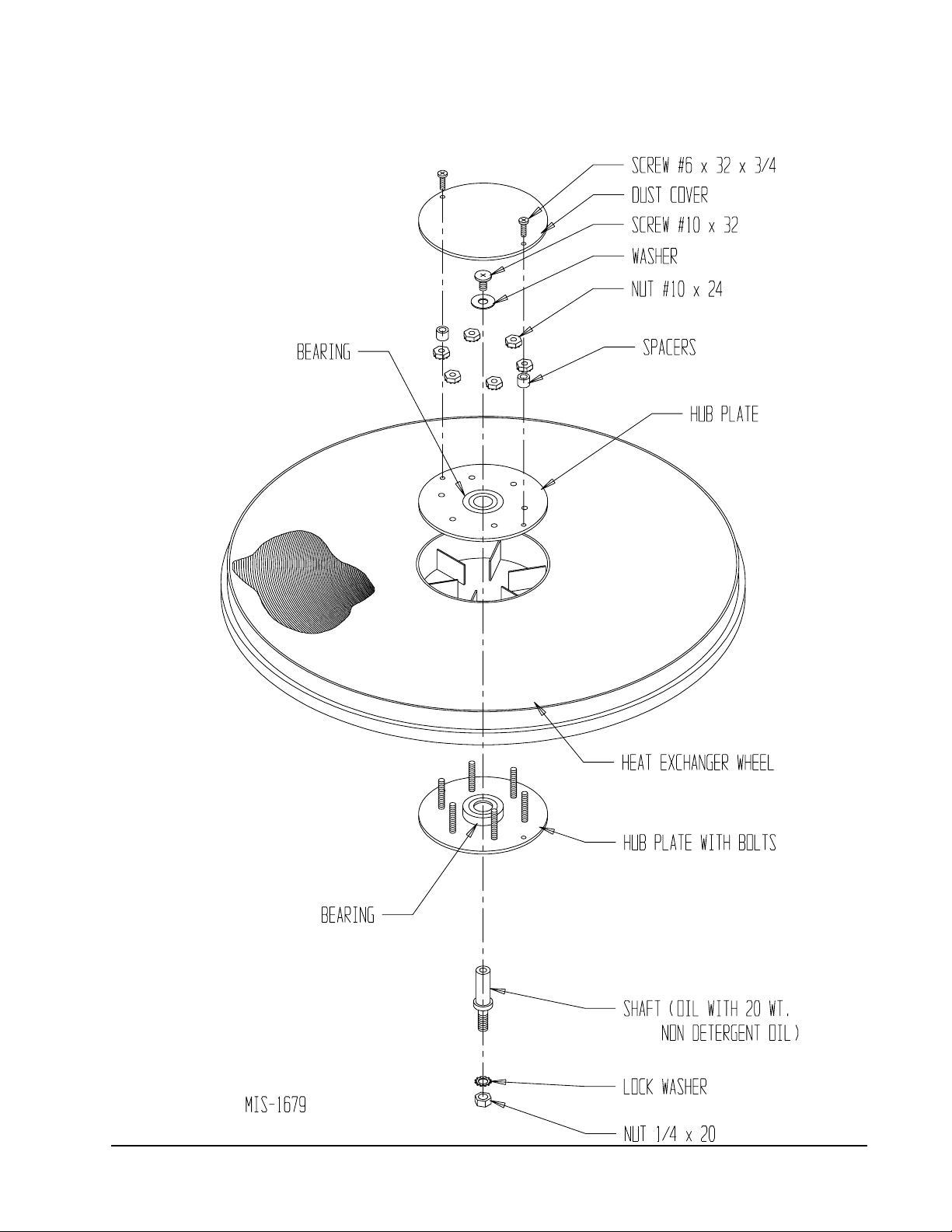
FIGURE 2
HUB ASSEMBLY WITH BALL BEARINGS
Manual 2100-310D
Page 7
 Loading...