


QTEC SERIES
PACKAGED
INSTALLATION
INSTRUCTIONS
AIR CONDITIONER
Models:
QA241D QA301D
QA361D QA421D
QA481D QA601D
Bard Manufacturing Company
Bryan, Ohio 43506
Since 1914 . . . Moving ahead, just as planned.
MIS-1554
Manual: 2100-438C
Supersedes: 2100-438B
File: Vol II Tab 14
Date: 06-02-04
© Copyright 2004

CONTENTS
Getting Other Information and Publications
For more information, contact these publishers: .......... 1
EC General Information
QT
EC Model Nomenclature .......................................... 2
QT
Shipping Damage ......................................................... 7
Unit Removal From Skid .............................................. 7
Handling Unit After Removal From Skid....................... 8
General ......................................................................... 8
Minimum Installation Height ......................................... 8
Duct Work .................................................................. 10
Filters .......................................................................... 10
Fresh Air Intake .......................................................... 11
Condensate Drain ...................................................... 11
Separate Evaporator Drain Connection ..................... 11
Service Light ............................................................... 12
Installation Instructions
Mounting the Unit ....................................................... 13
Wiring — Main Power ................................................. 14
Wiring — Low Voltage Wiring..................................... 14
Low Voltage Connections........................................... 15
General ....................................................................... 15
Start Up
Description of Standard Equipment ............................... 20
Optional CFM (QA361, QA421, QA481
and QA601 Only) ........................................................... 20
Important Installer Note.................................................. 20
Phase Monitor ................................................................ 20
Three Phase Scroll Compressor Start Up
Information ................................................................ 20
Compressor Control Module .......................................... 21
Adjustments ................................................................... 21
Service Hints .................................................................. 21
Mist Eliminator Service .................................................. 22
Vent Options .................................................................. 22
Sequence of Operation .................................................. 26
CRV / QERV Operation.................................................. 26
Optional Climate Controls Sequence
of Operation .............................................................. 26
Pressure Service Ports .................................................. 26
Troubleshooting
Troubleshooting Table .................................................... 29
Fan Blade Setting Dimensions ...................................... 30
Refrigerant Charge ........................................................ 30
Pressure Chart ............................................................... 31
Figures
Figure 1 Unit Dimensions .......................................... 6
Figure 2 Air Seal on Bottom of Unit ........................... 7
Figure 3 Removal of Unit From Skid ......................... 7
Figure 4 Unit on Appliance Cart for Moving ............... 8
Figure 5 Installation With Free Blow Plenum ............ 9
Figure 6 Ducted Application ....................................... 9
Figure 7 Supply Duct Connections .......................... 10
Figure 8 Filter Location ............................................ 10
Figure 9 Side Drain .................................................. 11
Figure 10 Optional Rear Drain ................................... 11
Figure 11 Rear Drain (Top View) ............................... 12
Figure 12 Unit Mounting ............................................ 12
Figure 13 Screws in Wheels of Unit .......................... 13
Figure 14 Component Location ................................. 14
Figure 15 Thermostat Plug Terminals ........................ 16
Figure 16 Thermostat Wiring Diagram "X" Option .... 17
Figure 17 Thermostat Wiring Diagram "G" Option ... 18
Figure 18 Thermostat Wiring Diagram "E" Option .... 19
Figure 19 Fresh Air Damper Removal ....................... 24
Figure 20 QERV Removal ......................................... 25
Figure 21 Air Conditioning Mode Circuit Diagram ..... 27
Figure 22 Dehumidification Mode Circuit Diagram .... 27
Figure 23 Fan Blade Setting ...................................... 30
Tables
Table 1 Factory Built-In Electric Heat Table .............. 3
Table 2 Electrical Specifications ................................ 4
Table 2A Electrical Specifications ................................ 5
Table 3 Operating Voltage Range ........................... 14
Table 4 Wall Thermostats and Subbase
Combinations .............................................. 16
Table 5 Troubleshooting .......................................... 29
Table 6 Fan Blade Dimensions ............................... 30
Table 7 Super Heat at Compressor ......................... 30
Table 8 Indoor Blower Performance ........................ 30
Table 9 Cooling Pressure ........................................ 31
i

GETTING OTHER INFORMATION AND PUBLICATIONS
These publications can help you install the air
conditioner or heat pump. You can usually find these at
your local library or purchase them directly from the
publisher. Be sure to consult current edition of each
standard.
National Electrical Code ..................... ANSI/NFPA 70
Standard for the Installation ............. ANSI/NFPA 90A
of Air Conditioning and
Ventilating Systems
Standard for Warm Air ...................... ANSI/NFPA 90B
Heating and Air
Conditioning Systems
Load Calculation for .......................ACCA Manual J or
Winter and Summer Manual N
Air Conditioning
Low Pressure, Low Velocity ........ ACCA Manual D or
Duct System Design Manual Q
Winter and Summer
Air Conditioning
FOR MORE INFORMATION, CONTACT
THESE PUBLISHERS:
ACCA Air Conditioning Contractors of America
1712 New Hampshire Avenue
Washington, DC 20009
Telephone: (202) 483-9370
Fax: (202) 234-4721
ANSI American National Standards Institute
11 West Street, 13th Floor
New York, NY 10036
Telephone: (212) 642-4900
Fax: (212) 302-1286
ASHRAE American Society of Heating, Refrigeration,
and Air Conditioning Engineers, Inc.
1791 Tullie Circle, N.E.
Atlanta, GA 30329-2305
Telephone: (404) 636-8400
Fax: (404) 321-5478
NFPA National Fire Protection Association
Batterymarch Park
P.O. Box 9101
Quincy, MA 02269-9901
Telephone: (800) 344-3555
Fax: (617) 984-7057
Manual 2100-438
Page 1
QT
EC
Series General Information
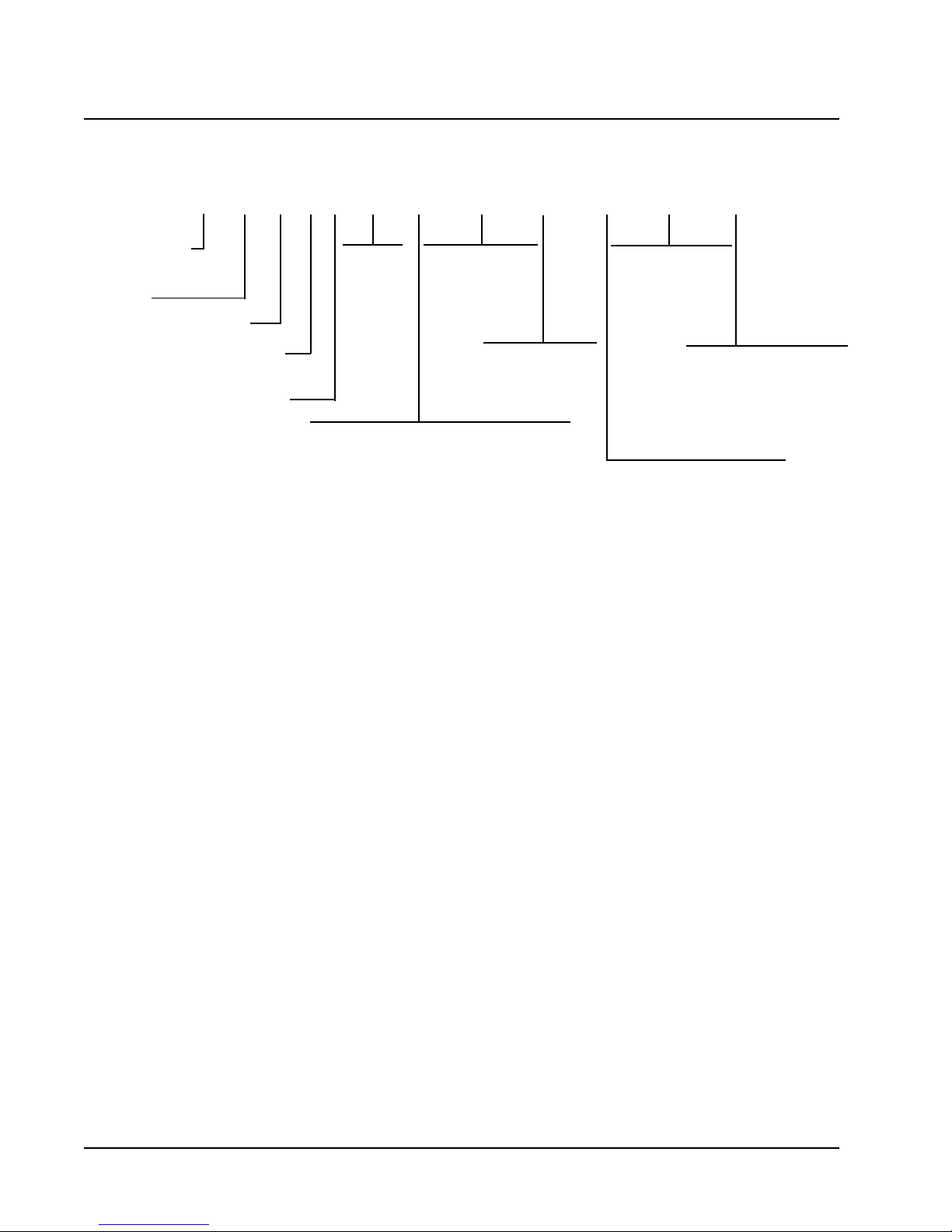
QTEC MODEL NOMENCLATURE
QA 36 1 D A 10 X X V X X X
MODEL NUMBER |
QA - QTEC Model
CAPACITY |
24 - 2 Ton
30 - 2-1/2 Ton
36 - 3 Ton
42 - 3-1/2 Ton
48 - 4 Ton
60 - 5 Ton
DEHUMDIFICATION |
REHEAT CYCLE
REVISION |
VOLTS & PHASE |
A - 230/208/60/1
B - 230/208/60/3
C - 460/60/3
KW
0Z -0KW
05 - 5KW
06 - 6KW
09 - 9KW
10 - 10KW
12 - 12KW
15 - 15KW
VENTILATION OPTIONS
X - Barometric Fresh Air Damper (Standard)
B - Blank-off Plate
V - Commercial Ventilator - Motorized w/Exhaust
Spring Return
P - Commercial Ventilator - Motorized w/Exhaust
Power Return
R - Energy Recovery Ventilator w/Exhaust
FILTER OPTIONS
X - 1 Inch Fiberglass
(Standard)
F - 2 Inch Fiberglass
P - 2 Inch Pleated
COLOR OPTIONS
V - Platinum w/Slate
Front (Vinyl)
4 - Gray paint
COIL OPTIONS
X - Standard
1 - Coated Evap. Coil
2 - Coated Cond.
Coil
3 - Coated Evap. &
Cond. Coil
I
NTERNAL CONTROLS
X - Standard
• High Pressure Switch
• Compressor Time Delay
G - LPC (Low Pressure
Control)
CLIMATE CONTROL OPTIONS
X - None
G - Electronic/Non Prog/Man C/O
with Humidistat
E - Electronic/Prog/Man/Auto
with Humidistat
Manual 2100-438
Page 2
CD163AQ
CD124AQ
CD184AQAD106AQBD106AQCD106AQ
BD163AQ
BD124AQ
BD184AQ
AD163AQ
AD124AQ
AD184AQ
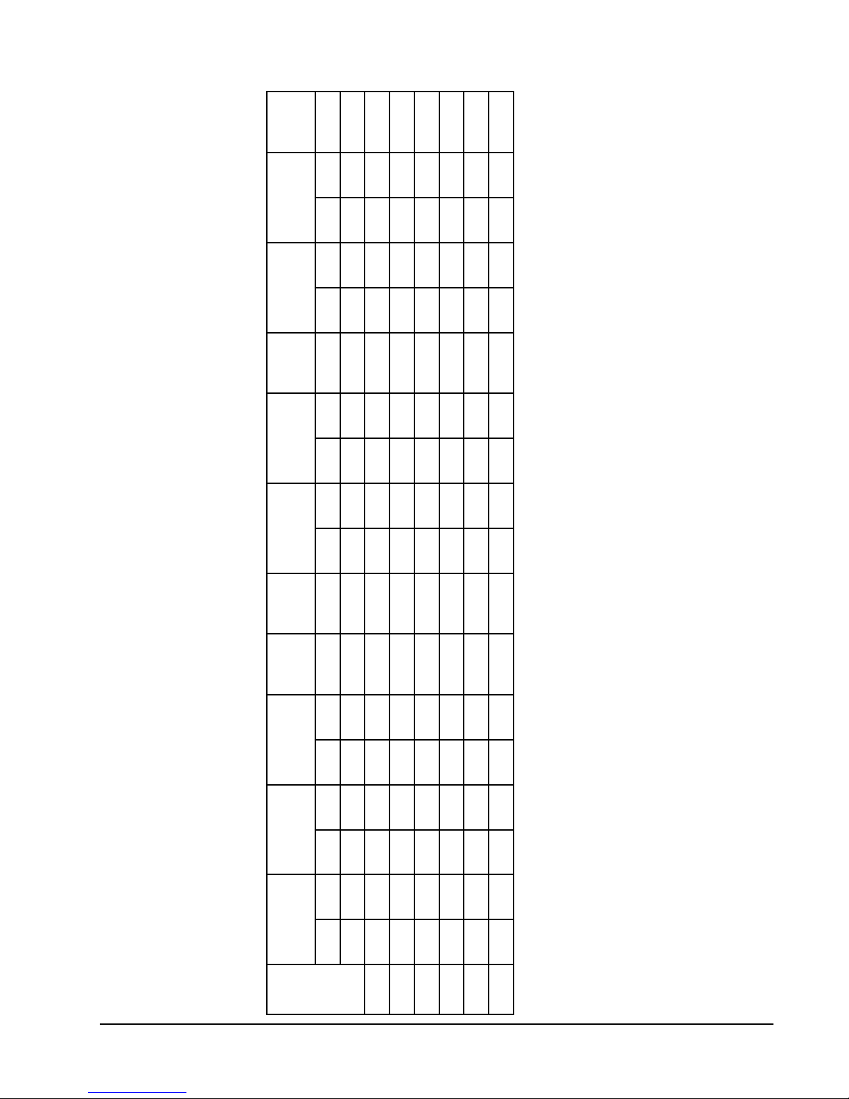
TABLE 1
FACTORY BUILT-IN ELECTRIC HEAT TABLE
AD142AQ
AD103AQBD142AQBD103AQCD142AQCD103AQ
1-V0421-V8021-V0421-V8021-V0421-V8023-V0843-V0841-V0421-V8021-V0421-V8023-V0841-V0421-V8021-V0421-V8023-V084
sledoM
0.5083,61092,21 083,61092,21
WKHUTBHUTBHUTBHUTBHUTBHUTBHUTBHUTBHUTBHUTBHUTBHUTBHUTBHUTBHUTBHUTBHUTBHUTB
0.9007,03000,32007,03000,32007,03007,03007,03000,32007,03007,03000,32007,03
0.6005,02063,51005,02063,51005,02005,02005,02063,51005,02
0.21000,14007,03000,14
0.01076,23075,42 076,23075,42076,23075,42
0.51 051,94068,63051,94068,63051,94051,94068,63051,94068,63051,94
Manual 2100-438
Page 3

TABLE 2
ELECTRICAL SPECIFICATIONS
TIUCRICELGNIS TIUCRICLAUD
D 51A
D 51B
D 51C
3
DETAR
SLEDOM
Z0AD142AQ
50AD
01AD
Z0BD142AQ
60BD
90BD
Z0CD142AQ
60CD
90CD
Z0AD103AQ
50AD
01AD
Z0BD103AQ
60BD
90BD
21BD
Z0CD103AQ
60CD
90CD
21CD
Z0AD163AQ
50AD
01AD
Z0BD163AQ
60BD
90BD
Z0CD163AQ
60CD
90CD
&STLOV
SESAHP
1-802/032
3-802/032
3-064
1-802/032
3-802/032
3-064
3-802/032
3-802/032
3-064
.ON
DLEIF
REWOP
STIUCRIC
1
1
1
1
1
1
1
1
1
1
1
1
1
1
1
1
1
1
1
1
1
1
1
2RO1
1
1
1
1
1
1
1
1
MUMINIM
TIUCRIC
02
03
55
51
42
33
8
21
71
52
23
75
81
52
43
34
01
41
81
32
82
33
85
38
12
62
53
35
11
41
81
72
1
YTICAPMA
03
03
06
02
52
53
51
51
02
53
53
06
52
52
53
54
51
51
02
52
53
53
06
09
03
03
53
06
51
51
02
03
2
MUMIXAM
LANRETXE
ROESUF
TIUCRIC
REKAERB
ERIW
EZIS
01
01
6
21
01
8
41
41
21
8
8
6
01
01
8
6
41
41
21
01
8
8
6
4
01
01
8
6
41
41
21
01
2
DLEIF
REWOP
ERIW
EZIS
01
01
01
21
01
01
41
41
21
01
01
01
01
01
01
01
41
41
21
01
01
01
8
8
01
01
01
01
41
41
21
01
3
MUMINIM
TIUCRIC
DNUORG
YTICAPMA
TKC
A
B
--
--
--
--
--
--
--
--
--
--
--
--
--
--
--
--
--
--
--
--
--
--
--
--
--
--
--
--
--
--
--
--
--
--
--
--
--
--
--
--
--
--
--
--
--
--
85
52
--
--
--
--
--
--
--
--
--
--
--
--
--
--
--
--
1
MUMIXAM
ROESUF
TIUCRIC
TKC
TKC
A
B
--
--
--
--
--
--
--
--
--
--
--
--
--
--
--
--
--
--
--
--
--
--
--
--
--
--
--
--
--
--
--
--
--
--
--
--
--
--
--
--
--
--
--
--
--
--
06
52
--
--
--
--
--
--
--
--
--
--
--
--
--
--
--
--
2
LANRETXE
REKAERB
TKC
DLEIF
REWOP
TKC
A
B
--
--
--
--
--
--
--
--
--
--
--
--
--
--
--
--
--
--
--
--
--
--
--
--
--
--
--
--
--
--
--
--
--
--
--
--
--
--
--
--
--
--
--
--
--
--
6
01
--
--
--
--
--
--
--
--
--
--
--
--
--
--
--
--
2
EZISERIW
TKC
DNUORG
EZISERIW
TKC
TKC
A
B
--
--
--
--
--
--
--
--
--
--
--
--
--
--
--
--
--
--
--
--
--
--
--
--
--
--
--
--
--
--
--
--
--
--
--
--
--
--
--
--
--
--
--
--
--
--
01
01
--
--
--
--
--
--
--
--
--
--
--
--
--
--
--
--
Maximum size of the time delay fuse or HACR type circuit breaker for protection of field wiring conductors.
!
Based on 75° C copper wire. All wiring must conform to the National Electrical Code and all local codes.
"
These “Minimum Circuit Ampacity” values are to be used for sizing the field power conductors. Refer to the National
#
Electric Code (latest revision), article 310 for power conductor sizing. CAUTION: When more than one field
power conductor circuit is run through one conduit, the conductors must be derated. Pay special attention to Note
8 of Table 310 regarding Ampacity Adjustment Factors when more than three conductors are in a raceway.
ELECTRICAL SPECIFICATIONS CONTINUED ON PAGE 5 TABLE 2A
Manual 2100-438
Page 4

D51A
D51B
D51C
D51A
D51B
D51C
D51A
D51B
D51C
TABLE 2A
ELECTRICAL SPECIFICATIONS
TIUCRICELGNIS TIUCRICLAUD
3
.ON
DETAR
LEDOM
Z0AD124AQ
50AD
01AD
Z0BD124AQ
60BD
90BD
Z0CD124AQ
60CD
90CD
Z0AD184AQ
50AD
01AD
Z0BD184AQ
50BD
01BD
Z0CD184AQ
60CD
90CD
Z0AD106AQ
01AD
Z0BD106AQ
90BD
Z0CD106AQ
90CD
&STLOV
ESAHP
1-802/032
3-802/032
3-064
1-802/032
3-802/032
3-064
1-802/032
3-802/032
3-064
DLEIF
REWOP
STIUCRIC
1
1
1
2RO1
1
1
1
1
1
1
1
1
1
1
1
2RO1
1
1
1
1
1
1
1
1
1
1
2ro1
1
1
1
1
1
1
MUMINIM
TIUCRIC
33
33
85
38
52
62
53
35
31
41
81
72
53
53
85
38
62
62
53
35
41
41
81
72
64
95
48
23
63
55
71
91
82
1
YTICAPMA
05
05
06
09
53
53
53
06
51
51
02
03
05
05
06
09
53
53
04
06
51
51
02
03
06
06
09
54
54
06
02
02
03
2
MUMIXAM
LANRETXE
ROESUF
TIUCRIC
REKAERB
ERIW
EZIS
8
8
6
4
8
8
8
6
41
41
21
01
8
8
6
4
8
8
8
6
21
21
21
01
8
6
4
8
8
6
21
21
01
2
DLEIF
REWOP
ERIW
EZIS
01
01
8
8
01
01
01
01
41
41
21
01
01
01
01
8
01
01
01
01
21
21
21
01
01
01
8
01
01
01
21
21
01
3
MUMINIM
TIUCRIC
DNUORG
YTICAPMA
TKC
A
B
--
--
--
--
--
--
85
52
--
--
--
--
--
--
--
--
--
--
--
--
--
--
--
--
--
--
--
--
--
--
85
52
--
--
--
--
--
--
--
--
--
--
--
--
--
--
--
--
--
--
--
--
95
52
--
--
--
--
--
--
--
--
--
--
--
--
1
MUMIXAM
ROESUF
TIUCRIC
REKAERB
TKC
TKC
A
B
--
--
--
--
--
--
06
52
--
--
--
--
--
--
--
--
--
--
--
--
--
--
--
--
--
--
--
--
--
--
06
52
--
--
--
--
--
--
--
--
--
--
--
--
--
--
--
--
--
--
--
--
06
52
--
--
--
--
--
--
--
--
--
--
--
--
2
LANRETXE
TKC
DLEIF
REWOP
EZISERIW
TKC
A
B
--
--
--
--
--
--
6
01
--
--
--
--
--
--
--
--
--
--
--
--
--
--
--
--
--
--
--
--
--
--
8
01
--
--
--
--
--
--
--
--
--
--
--
--
--
--
--
--
--
--
--
--
8
01
--
--
--
--
--
--
--
--
--
--
--
--
2
DNUORG
EZISERIW
TKC
TKC
A
TKC
B
--
--
--
--
--
--
01
01
--
--
--
--
--
--
--
--
--
--
--
--
--
--
--
--
--
--
--
--
--
--
01
01
--
--
--
--
--
--
--
--
--
--
--
--
--
--
--
--
--
--
--
--
01
01
--
--
--
--
--
--
--
--
--
--
--
--
Maximum size of the time delay fuse or HACR type circuit breaker for protection of field wiring conductors.
!
Based on 75° C copper wire. All wiring must conform to the National Electrical Code and all local codes.
"
These “Minimum Circuit Ampacity” values are to be used for sizing the field power conductors. Refer to the National
#
Electric Code (latest revision), article 310 for power conductor sizing. CAUTION: When more than one field power
conductor circuit is run through one conduit, the conductors must be derated. Pay special attention to Note 8 of
Table 310 regarding Ampacity Adjustment Factors when more than three conductors are in a raceway.
Manual 2100-438
Page 5

FIGURE 1
UNIT DIMENSIONS
Manual 2100-438
Page 6
SHIPPING DAMAGE
Upon receipt of equipment, the carton should be
checked for external signs of shipping damage. The
skid must remain attached to the unit until the unit is
ready for installation. If damage is found, the receiving
party must contact the last carrier immediately,
preferably in writing, requesting inspection by the
carrier’s agent.
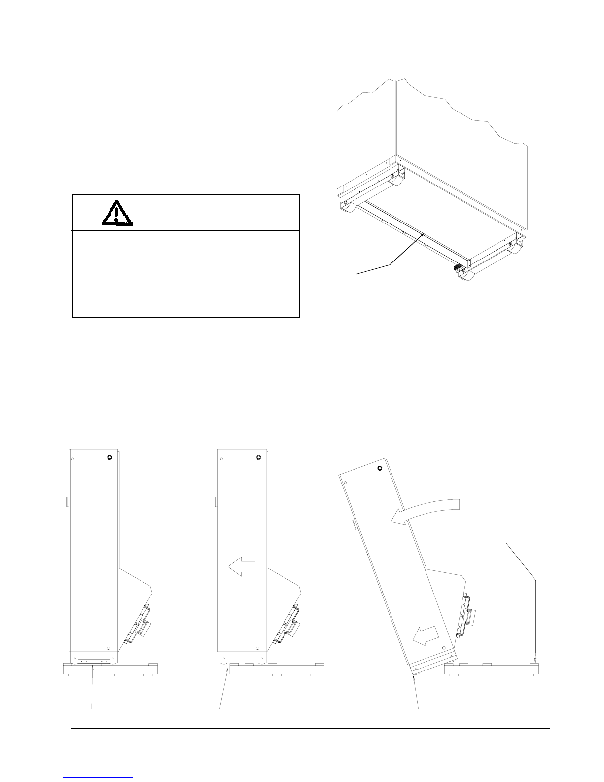
UNIT REMOVAL FROM SKID
WARNING
This unit is heavy and requires more than one
person to handle and remove from the skid.
Check unit wheels to ensure that wheels are
locked before removing from skid. Extreme
caution must be taken to prevent injury to
personnel and damage to the unit.
It is recommended that the unit not be removed from
the skid with a fork lift since the air seal under the unit
could be damaged. See Figure 2.
The shipping brackets on each side of the unit must be
removed and discarded. See Figure 3-A. The return air
grille panel can be removed to provide a place to hold
FIGURE 2
AIR SEAL UNDER QT
Air Seal
the unit. The unit can be slid forward on the skit until
the front wheels hang over the edge of the skid. See
Figure 3-B. The unit can be tipped forward and slid
down the edge of the skid until the front wheels touch
the ground. See Figure 3-C. The wheels will not roll.
They are shipped from the factory locked so they will
not roll. The back of the skid will have to be held down
to keep it from tipping up. The skid can be slid out from
under the unit. The unit can then be set upright.
EC
UNIT
MIS-1008
FIGURE 3
REMOVAL OF UNIT FROM SKID
Hold Skid Down
A Shipping Brackets B Front Wheels Over Edge C Front Wheels On Floor
MIS-1007
Manual 2100-438
Page 7
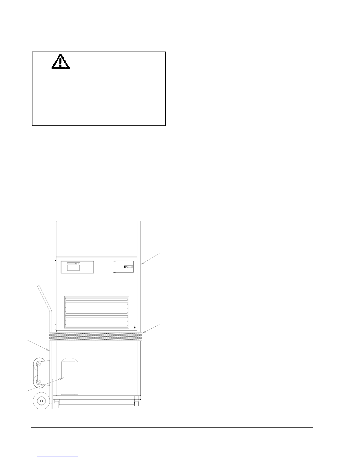
HANDLING UNIT AFTER REMOVAL
FROM SKID
WARNING
Exercise extreme caution when pushing the
unit on the rollers. Handle and push from the
lower 1/3 of the unit. Insure that debris is not
on the floor where the unit is to be moved on
the rollers. Failure to do so could result in the
unit tipping over and causing bodily injury and/
or damage to the unit.
The unit will have to be turned sideways and removed
from the skid to fit through a 36” doorway. If the door
height allows, the unit can be slid sideways through the
door.
If the unit can not be slid through the door, then the unit
will have to be put on a cart and tipped down to roll
through the door. It is recommended that an appliance
cart by used with a strap to hold the unit on the cart.
The wheels of the unit must be locked. If the wheels
were allowed to roll, the unit could roll off the cart. The
unit should always be carted from the left side. This is
the side where the compressor is located. See Figure 4.
The blade of the appliance cart should be slid under the
wheels of the unit. The strap of the appliance cart
should be placed around the unit and strapped tightly.
Help will be required to tip the unit back onto the cart.
The unit can be leaned far enough back to be rolled
through the door. Be careful when setting the unit back
up to keep from damaging the unit.
GENERAL
The equipment covered in this manual is to be installed
by trained, experienced service and installation
technicians.
The unit is designed for use with or without duct work.
For use without duct work, Plenum Box QPB42 is
recommended.
These instructions explain the recommended method to
install the air cooled self-contained unit and the
electrical wiring connections to the unit.
APPLIANCE
CART
FIGURE 4
UNIT ON APPLIANCE CART
QTEC UNIT
(Right Side)
STRAP
These instructions and any instructions packaged with
any separate equipment required to make up the entire
air conditioning system should be carefully read before
beginning the installation. Note particularly “Start
Procedure” and any tags and/or labels attached to the
equipment.
While these instructions are intended as a general
recommended guide, they do not supersede any national
and/or local codes in any way. Authorities having
jurisdiction should be consulted before the installation
is made. See Page 1 for information on codes and
standards.
Size of unit for a proposed installation should be based
on heat loss calculation made according to methods of
Air Conditioning Contractors of America (ACCA).
The air duct should be installed in accordance with the
Standards of the National Fire Protection Systems of
Other Than Residence Type, NFPA No. 90A, and
Residence Type Warm Air Heating and Air
Conditioning Systems, NFPA No. 90B. Where local
regulations are at a variance with instructions, installer
should adhere to local codes.
COMPRESSOR
Manual 2100-438
Page 8
MIS-1555
MINIMUM INSTALLATION HEIGHT
The minimum installation height of the unit with a Free
Blow Plenum is 8 ft. 6 in. This provides enough
clearance for the plenum to be removed. See Figure 5.
The minimum installation height for ducted applications
is 8 ft. 4-1/2 in. This provides enough clearance to
install the duct work. See Figure 6.

8 FT. - 5 IN.
FIGURE 5
INSTALLATION WITH FREE BLOW PLENUM
CEILING
8 FT. - 6 IN.
MINIMUM RECOMMENDED
CEILING HEIGHT
7 FT. - 4 IN.
UNIT HEIGHT
20 IN.
MINIMUM
FIGURE 6
DUCTED APPLICATION
SUSPENDED
CEILING
MINIMUM RECOMMENDED
FIXED CEILING
12 IN.
MINIMUM
2 IN. MINIMUM
FROM DUCT FLANGE
TO DUCT BOTTOM
8 FT. - 7 IN.
CEILING HEIGHT
FLOOR
MIS-1574
DUCT
DUCT FLANGE
8 FT. - 4.5 IN.
MINIMUM REQUIRED
INSTALLATION HEIGHT
FLOOR
MIS-1573
Manual 2100-438
Page 9

DUCT WORK
All duct work must be properly sized for the design air
flow requirement of the equipment. Air Conditioning
Contractors of America (ACCA) is an excellent guide to
proper sizing. All duct work or portions thereof not in
the conditioned space should be properly insulated in
order to both conserve energy and prevent condensation
or moisture damage. When duct runs through unheated
spaces, it should be insulated with a minimum of one
inch of insulation. Use insulation with a vapor barrier
on the outside of the insulation. Flexible joints should
be used to connect the duct work to the equipment in
order to keep the noise transmission to a minimum.
The QTEC series unit has provision to attach a supply air
duct to the top of the unit. Duct connection size is 12
inches x 20 inches. The duct work is field supplied and
must be attached in a manner to allow for ease of
removal when it becomes necessary to slide the unit out
from the wall for service. See Figure 7 for suggested
attachment method.
FIGURE 7
SUPPLY DUCT CONNECTIONS
SUPPLY DUCT
TO BE FIELD
SUPPLIED
For hot water coil option a QPBHWxx-F for free blow
or QPBHWxx-D for ducted airflow is used
When used with a ducted supply, a QCX Cabinet
Extension can be used to conceal the duct work above
the unit to the ceiling. This extends 20” above the unit
for a total height above the floor of 10’-7/8”. The unit is
equipped with a variable speed indoor blower motor
which increases in speed with an increase in duct static
pressure. The unit will therefore deliver proper rated air
flow up to the maximum ESP shown in Table 8.
However, for quiet operation of the air system, the duct
static should be kept as low as practical, within the
guidelines of good duct design.
FILTERS
Two 1 inch throw away filters [(1) 16x16 and (1) 16x20]
are supplied with each unit. The filters slide into filter
brackets. Refer to Figure 8.
The filters are serviced from the inside of the building
by opening the hinged door. This door is attached by
1/4 turn fasteners and one locking latch.
The internal filter brackets are adjustable to
accommodate 2 inch filters. The tabs for the 1 inch
filters must be bent down to allow the 2 inch filters to
slide in place.
FIGURE 8
FILTER LOCATION
ATTACHMENT
SCREWS TO
BE FIELD
SUPPLIED
ROOM SIDE OF
QTEC UNIT
DUCT FLANGE
MIS-978
PROVIDED WITH
UNIT
NOTE: Unit cabinet, supply air duct and free blow
plenum are approved for “0” clearance to
combustible material.
The QTEC series units are designed for use with free
return (non-ducted) and either free blow with the use of
QPB Plenum Box or a duct supply air system.
The QPB and QPBHW Plenum Box mounts on top of
the unit and has both vertically and horizontally
adjustable louvers on the front discharge grille.
FILTERS
RETURN AIR
GRILLE
Manual 2100-438
Page 10
MIS-1575

FRESH AIR INTAKE
This unit is equipped with a fresh air damper assembly.
The damper blade is locked in the closed position when
the unit is shipped from the Factory. To allow the
damper to operate remove the two plastic locking pins,
one on each end of the blade. This will allow for
maximum fresh air flow. The Damper blade will now
open when the indoor blower is operating. If less than
maximum fresh air flow is required, reinsert the plastic
pins to limit damper blade opening to desired level.
Two extra pins are provided (taped to the inside of the
assembly) which may be used to hold the blade in some
position other than minimum or maximum position.
This fresh air assembly is located in the rear of the unit
and to gain access to make these adjustments remove
the air filter service door.
All capacity, efficiency and cost of operation
information as required for Department of Energy
“Energyguide” Fact Sheets are based upon the fresh air
blank-off plate in place and is recommended for
maximum energy efficiency.
The blank-off plate is available upon request from the
factory and is installed in place of the fresh air damper
shipped with each unit.
For details on energy recovery ventilation see separate
section.
CONDENSATE DRAIN
There are two drain connections on the unit. The rear
drain is the primary drain, and is located on the right
lower rear panel of the unit. The optional side drain is
located on the bottom right side of the unit. The side
drain is shipped with a plug installed.
The side drain requires a water trap for proper drainage.
See Figure 9. The drain can be routed through the floor
or through the wall. If the drain is to be routed
through an unconditioned space, it must be protected
from freezing. The drain line must be able to be
removed from the unit if it is necessary to remove the
unit from the wall. When the side drain is used, the
plug must be removed and installed in the rear drain.
The rear drain can be used with wall thickness of up to
10 inches where a water trap can be installed between
the unit and the interior wall. See Figure 10. The trap
cannot extend beyond the edge of the unit or it will
interfere with the wall mounting bracket. The drain can
be routed through the floor or through the wall. If the
drain is routed through the wall, the drain line must be
positioned such that it will not interfere with the sleeve
flange or the grille. See Figure 11. If the drain is to be
routed through an unconditioned space, it must be
protected from freezing.
Optional rear drain kits, both standard and heated
versions, are available to facilitate easy installation, and
also removability of heat pump for service.
SEPARATE EVAPORATOR DRAIN
CONNECTION (OPTIONAL)
A knockout is provided in the back right corner of the
units for use when draining the evaporator drain pan
separately from the condenser. This knockout is 5
inches above the back condenser drain opening. To
utilize a separate evaporator drain connection remove
the knockout and route the existing evaporator drain
hose out this knockout and then to an appropriate drain
line.
FIGURE 9
SIDE DRAIN (SIDE VIEW)
QTEC UNIT
FIGURE 10
OPTIONAL REAR DRAIN
PLUG SIDE DRAIN
MIS-975
Manual 2100-438
Page 11

FIGURE 11
REAR DRAIN (TOP VIEW)
DRAIN LINE
WALL (MAXIMUM 10”
FOR REAR DRAIN)
SERVICE LIGHT
The unit is equipped with a service light which
signals the user that service is required. The light
is located in the upper control panel and is visible
only when the hinged service/filter access door is
open.
The Service Unit light indicates that the unit has
been shut off by a high or low pressure device.
This indicates that the unit needs to be serviced.
SLEEVE
WATER TRAP
MIS-977
COUPLINGS NOT
SHOWN BUT
RECOMMENDED
FOR EASE OF
REMOVABILITY
FOR SERVICE.
WALL BRACKET
UNIT
FIGURE 12
UNIT MOUNTING
SIDE TRIM
(2 PCS.)
BOTTOM
TRIM PIECE
Manual 2100-438
Page 12
BOTTOM TRIM
EXTENSION
MIS-1576
SIDE TRIM
(2 PCS.)
#8 SCREW
PROVIDED
(LIGHT COLOR)
MOUNTING
BRACKET
CABINET
SIDE PANEL
ENLARGED VIEW OF MOUNTING
BRACKET SHOWING SLEEVE TO
CABINET ATTACHMENT
MOUNTING BRACKET
MIS-1061
WALL
SLEEVE
#10 HEX
HEAD SCREW
PROVIDED

INSTALLATION INSTRUCTIONS
MOUNTING THE UNIT
When installing a QTEC unit near an interior wall on the
left side, a minimum of 8 inches is required; 12 inches is
preferred.
When installing a QTEC unit near an interior wall on the
right side, a minimum of 18 inches is required as
additional space is required to connect the side drain. If
the rear condensate drain kit QCDS48 is used the
minimum can be reduced to 8 inches.
This clearance is required to allow for the attachment of
the unit to the sleeve and side trim pieces to the wall.
This unit is to be secured to the wall sleeve with
mounting brackets provided. The unit itself, the supply
duct and the free blow plenum are suitable of “0”
clearance to combustible material.
Following are the steps for mounting the QT
reference see Figure 12 (page 11).
1. Attach mounting brackets to the wall sleeve with
screws provided.
2. Position the unit in front of the sleeve with the
condenser section toward the sleeve.
3. Remove the locking screws from the wheels.
Refer to Figure 13.
4. Roll the unit into the sleeve. Make sure to check
both sides of the unit as it is being rolled to keep
it centered in the sleeve. Also check the
EC
, for
alignment to the mounting brackets. This unit
must be level from side to side. If adjustments
are necessary, shim up under the rollers with
sheets of steel or any substance that is not
affected by moisture.
5. Make sure the gasket on the rear of the unit is
touching the sleeve across the top and down both
sides. This is a rain water seal.
6. Secure the mounting brackets to the unit with
screws provided, #10 hex head sheet metal
screws.
7. Bottom trim extensions are provided for use when
wall is less than 14 inches but greater than 10.5
inches. Secure to wall with screws (not
provided).
8. Attach the bottom trim piece to the unit with the
screws provided (dark colored).
9. Position side trim pieces to wall and attach with
field supplied screws. There are two long pieces
and two short pieces supplied. The long pieces
are to enclose the gap behind the unit. The short
pieces are to fill the gap behind the cabinet
extension or the free blow plenum box. The may
be cut to suit your ceiling height or overlap the
unit side trim. There is sufficient length to trim
up to a 10’2” ceiling.
NOTE: If the exterior wall thickness is between 5
inches to 10.5 inches, a side trim extension
piece kit, model QSTX42A, is available.
REMOVING LOCKING SCREWS FROM WHEELS
FIGURE 13
REMOVE SCREWS
FROM WHEELS
BEFORE ROLLING
INTO PLACE
MIS-1018
Manual 2100-438
Page 13

WIRING – MAIN POWER
Refer to the unit rating plate and/or Table 2 for wire
sizing information and maximum fuse or “HACR Type”
circuit breaker size. Each unit is marked with a
“Minimum Circuit Ampacity”. This means that the
field wiring used must be sized to carry that amount of
current. Depending on the installed KW of electric
heat, there may be two field power circuits required. If
this is the case, the unit serial plate will so indicate. All
models are suitable only for connection with copper
wire. Each unit and/or wiring diagram will be marked
“Use Copper Conductors Only”. These instructions
MUST BE adhered to. Refer to the National Electrical
Code (NEC) for complete current carrying capacity data
on the various insulation grades of wiring material. All
wiring must conform to NEC and all local codes.
The electrical data lists fuse and wire sizes (75° C
copper) for all models, including the most commonly
used heater sizes. Also shown are the number of field
power circuits required for the various models with
heaters.
The unit rating plate lists a “Maximum Time Delay
Relay Fuse” or “HACR Type” circuit breaker that is to
be used with the equipment. The correct size must be
used for proper circuit protection, and also to assure that
there will be no nuisance tripping due to the momentary
high starting current of the compressor motor.
The disconnect access door on this unit may be locked
to prevent unauthorized access to the disconnect.
See Start Up section for information on three phase
scroll compressor start-ups.
The field wiring connections are located behind the top
and hinged panel in the circuit breaker panel. See
Figure 14.
WIRING – LOW VOLTAGE WIRING
230/208V, 1 PHASE AND 3 PHASE EQUIPMENT
DUAL PRIMARY VOLTAGE TRANSFORMERS.
All Equipment leaves the factory wired on 240V tap.
For 208V operation, reconnect form 240V to 208V tap.
The acceptable operating voltage range for the 240 and
208V taps are as noted in Table 3.
TABLE 3
OPERATING VOLTAGE RANGE
PATEGNAR
V042612–352
V802791–022
ELECTRIC
HEATERS
UNIT
MOUNTED
THERMOSTAT
LOCATION
DEHUMIDIFICATION
CONTROL
(OPTIONAL)
FIGURE 14
COMPONENT LOCATION
SIDE FIELD WIRE
ENTRANCE
REMOTE
THERMOSTAT
TERMINAL
BLOCK
I
NDOOR
BLOWER
CIRCUIT
BREAKER PANEL
& CONTROLS
LOWER
CONTROL
PANEL
NOTE: The voltage should be measured at the filed
power connection point in the unit and while
the unit is operating at full load (maximum
amperage operating condition).
The standard Climate Control Option X is a remote
thermostat connection terminal block. See Figure 16 for
wiring diagram. Compatible thermostats are listed in
Table 4.
The Climate Control Option G is an electronic, non-
programmable manual or auto changeover thermostat.
The subbase of the thermostat is factory wired to the
front panel of the unit. The humidistat is included. See
Figure 17 for wiring diagram. Compatible for use with
Bard CS2000 Controller and Energy Recovery
Ventilator.
The Climate Control Option E is an electronic,
programmable thermostat. The subbase of the
thermostat is factory wired to the front panel of the unit.
The humidistat is included. See Figure 18 for wiring
diagram. Compatible for use with Energy Recovery
Ventilator.
NOTE: On option X or G the CS2000 (or other field
provided means to control ventilation) must be
used if any of the motorized ventilation options
are installed.
Manual 2100-438
Page 14
MIS-1577

LOW VOLTAGE CONNECTIONS
These units use a grounded 24 volt AC low voltage
circuit.
LOW VOLTAGE CONNECTIONS
FOR DDC CONTROL
The “R” terminal is the hot terminal and the “C”
terminal is grounded.
“G” terminal or pin 6 of P2 are the fan inputs. If the
climate control option is abandoned and connections are
made directly to P2 pin 6 of P2 must be energized for
proper operation.
“Y” terminal or pin 7 of P2 is the compressor input.
“W1” terminal or pin 8 of P2 is the fist stage heat.
“R” terminal or pin 10 of P2 is 24 VAC hot.
“C” terminal or pin 11 of P2 is 24 VAC grounded.
Terminal “1” or pin 4 of P2 is the dehumidification
circuit.
Terminal “2” or pin 12 of P2 is the dehumidification
circuit. A contact must connect terminals 4 and 5.
“W2” terminal or pin 9 of P2 is second stage heat (if
equipped). If the unit is equipped with an optional hot
water coil plenum box or electric heat these will be
energized by this terminal.
“F” terminal of pin 5 of P2 is the ventilation input.
This terminal energizes any factory installed ventilation
option.
Fan Only Energize G
Cooling Mode Energize Y, G
1st Stage Heating Energize G, W1
2nd State Heating Energize G, W2
(if employed)
Ventilation Energize G, O1
Dehumidification Energize contact
between 1 and 2
GENERAL
This unit is equipped with a variable speed ECM motor.
The motor is designed to maintain rated airflow up to
the maximum static allowed. It is important that the
blower motor plugs are not plugged in or unplugged
while the power is on. Failure to remove power prior
to unplugging or plugging in the motor could result in
motor failure.
NOTE: For total and proper control using DDC, a
total of 6 controlled outputs are required (5 if
no ventilation system is installed).
CAUTION
Do not plug in or unplug blower motor
connectors while the power is on. Failure to do
so may result in motor failure.
Manual 2100-438
Page 15

TABLE 4
WALL THERMOSTATS AND SUBBASE COMBINATIONS
tatsomrehTesabbuSserutaeFtnanimoderP
940-3048
)083-39F1(
050-3048
)5101D4258T(
A/N
A/N
elbammargorP
looC/taeH/otuA/launaM
looC/taeH/otuA/launaM
cinortcelEelbammargorP-noN
FIGURE 15
THERMOSTAT PLUG TERMINALS
P2 AND P4
(VIEWED FROM PIN END)
BLOWER MOTOR
LOW VOLTAGE PLUG
(VIEWED FROM PIN END)
Manual 2100-438
Page 16
MIS-1285

FIGURE 16
REMOTE THERMOSTAT WIRING DIAGRAM
“X” THERMOSTAT OPTION
NOTE: On option X or G the CS2000 (or other field
provided means to control ventilation) must be
used if any of the motorized ventilation options
are installed.
Manual 2100-438
Page 17

FIGURE 17
UNIT MOUNTED THERMOSTAT WIRING DIAGRAM
“G” THERMOSTAT OPTION
NOTE: On option X or G the CS2000 (or other field
provided means to control ventilation) must be used
if any of the motorized ventilation options are
installed.
Manual 2100-438
Page 18

FIGURE 18
UNIT MOUNTED THERMOSTAT WIRING DIAGRAM
“E” THERMOSTAT OPTION
Manual 2100-438
Page 19

START UP
DESCRIPTION OF STANDARD
EQUIPMENT
High Pressure Switch
Provides refrigerant circuit high pressure protection.
Includes lockout circuit that is resettable from room
thermostat.
Compressor Control Module
Provides short cycle protection for the compressor
which extends compressor life. High and low pressure
switch monitoring and alarm functions.
Service Lights
One service light indicates when service is required.
• Check System – detects high or low pressure
switch operation for compressor protection.
OPTIONAL CFM (QA361, QA421, QA481
AND QA601 ONLY)
These units are shipped from the factory set to operate at
the optional CFM level shown in Table 8. This provides
lower operating sound levels for non-ducted, free
discharge applications. This CFM level will reduce the
system capacity performance by approximately 2% at
the same energy efficiency.
Rated CFM is required for ducted applications for
maximum performance rating. To obtain full CFM on
these models, connect jumper wire as follows:
1. Disconnect all power to the unit. Failure to do so
may result in damage to the motor.
2. Open return air service panel
3. Open inner control panel cover
4. Locate low voltage terminal strip. There is a pink
jumper wire with both ends attached to terminal
marked “G2”. Move one end of this jumper to
terminal “Y”.
5. Reverse steps to reassemble.
IMPORTANT INSTALLER NOTE
For improved start-up performance, wash the indoor coil
with a dishwasher detergent.
This unit is equipped with a variable speed ECM motor.
The motor is designed to maintain rated airflow up to
the maximum Static allowed. It is important that the
blower motor plugs are not plugged in or unplugged
while the power is on. Failure to remove power prior
to unplugging or plugging in the motor could result in
motor failure.
CAUTION
Do not plug in or unplug blower motor
connectors while the power is on. Failure to
do so may result in motor failure.
PHASE MONITOR
All units with three phase scroll compressors are
equipped with a 3 phase line monitor to prevent
compressor damage due to phase reversal.
The phase monitor in this unit is equipped with two
LEDs. If the Y signal is present at the phase monitor
and phases are correct the green LED will light and the
compressor contactor is allowed to energize.
If phases are reversed, the red fault LED will be lit and
compressor operation is inhibited.
If a fault condition occurs, reverse two of the supply
leads to the unit. Do not reverse any of the unit factory
wires as damage may occur.
THREE PHASE SCROLL COMPRESSOR
START UP INFORMATION
Scroll compressors, like several other types of
compressors, will only compress in one rotational
direction. Direction of rotation is not an issue with
single phase compressors since they will always start
and run in the proper direction.
However, three phase compressors will rotate in either
direction depending upon phasing of the power. Since
there is a 50-50 chance of connecting power in such a
way as to cause rotation in the reverse direction,
verification of proper rotation must be made.
Verification of proper rotation direction is made by
observing that suction pressure drops and discharge
pressure rises when the compressor is energized.
Reverse rotation also results in an elevated sound level
over that with correct rotation, as well as, substantially
reduced current draw compared to tabulated values.
Verification of proper rotation must be made at the
time the equipment is put into service. If improper
rotation is corrected at this time there will be no
negative impact on the durability of the compressor.
However, reverse operation for oven one hour may
have a negative impact on the bearing due to oil pump
out.
Manual 2100-438
Page 20

All three phase scroll compressors used in the QT
EC
series are wired identically internally. As a result, once
the correct phasing is determined for a specific system
or installation, connecting properly phased power leads
to the same Fusite terminal should maintain proper
rotation direction. The direction of rotation of the
motor may be changed by reversing any two line
connections to the unit.
COMPRESSOR CONTROL MODULE
The compressor control module is standard on all
models covered by this manual. The compressor
control is an anti-short cycle/lockout timer with high
and low pressure switch monitoring and alarm relay
output.
Adjustable Delay On Make And Break Timer
On initial power up or any time power is interrupted to
the unit the delay on make period begins which will be
2 minutes plus 10% of the delay on break setting.
When the delay on make is complete and the high
pressure switch (and low pressure switch if employed)
is closed, the compressor contactor is energized. Upon
shutdown the delay on break timer starts and prevents
restart until the delay on break and delay on make
periods have expired.
During routine operation of the unit with no power
interruptions the compressor will operate on demand
with no delay.
High Pressure Switch and Lockout Sequence
If the high pressure switch opens, the compressor
contactor will de-energize immediately. The lockout
timer will go into a soft lockout and stay in soft lockout
until the high pressure switch closes and the delay on
break time has expired. If the high pressure switch
opens again in this same operating cycle the unit will
go into manual lockout condition and the alarm relay
circuit will energize. Recycling the wall thermostat
resets the manual lockout.
Low Pressure Switch, Bypass, and Lockout
Sequence
If the low pressure switch opens for more than 120
seconds, the compressor contactor will de-energize and
go into a soft lockout. Regardless the state of the low
pressure switch, the contactor will reenergize after the
delay on make time delay has expired. If the low
pressure switch remains open, or opens again for longer
than 120 seconds the unit will go into manual lockout
condition and the alarm relay circuit will energize.
Recycling the wall thermostat resets the manual
lockout.
Alarm Relay Output
Alarm terminal is output connection for applications
where alarm relay is employed. This terminal is
powered whenever compressor is locked out due to HPC
or LPC sequences as described.
NOTE: Both high and low pressure switch controls are
inherently automatic reset devices. The high
pressure switch and low pressure switch cut out
and cut in settings are fixed by specific air
conditioner or heat pump unit model. The
lockout features, both soft and manual, are a
function of the Compressor Control Module.
ADJUSTMENTS
Adjustable Delay on Make and Delay on Break
Timer
The potentiometer is used to select Delay on Break time
from 30 seconds to 5 minutes. Delay on Make (DOM)
timing on power-up and after power interruptions is
equal to 2 minutes plus 10% of Delay on Break (DOB)
setting:
0.5 minute (30 seconds) DOB = 123 second DOM
1.0 minute (60 seconds) DOB = 126 second DOM
2.0 minute (120 seconds) DOB = 132 second DOM
3.0 minute (180 seconds) DOB = 138 second DOM
4.0 minute (240 seconds) DOB = 144 second DOM
5.0 minute (300 seconds) DOB = 150 second DOM
During routine operation of the unit with no power
interruptions the compressor will operate on demand
with no delay.
Typical Settings for Dual Unit Installation:
Unit 1: DOB set at 2 minutes, and DOM is 132 seconds
Unit 2: DOB set at 4 minutes, and DOM is 144 seconds
SERVICE HINTS
1. Caution user to maintain clean air filters at all
times. Also, not to needlessly close off supply air
registers. This may reduce air flow through the
system, which shortens equipment service life as
well as increasing operating costs and noise
levels.
2. Check all power fuses or circuit breakers to be
sure they are the correct rating.
3. Periodic cleaning of the outdoor coil to permit
full and unrestricted airflow circulation is
essential.
Manual 2100-438
Page 21

6. Some service requires the need to remove the unit
from the wall including replacement of the indoor
coil and/or the outdoor coil. Also servicing the
outdoor fan motor or fan blade will require
removing the unit from the wall if the unit is
installed at a height that is not easily accessible
from the outside of the building.
In order to remove the unit from the wall the
following procedure must be used:
a. Turn off power to the unit at the remote
location. Some units may have more than one
power supply.
b. Disconnect field wiring at unit terminal block
and remove from unit.
c. Disconnect condensate drain.
d. Remove the lower skirting around the unit.
e. Remove wall mounting brackets from wall on
each side of the unit.
It is recommended that the mist eliminator be inspected
annually and serviced as required. The mist eliminator
can be inspected from the outside of the building by
looking through the outdoor grille. The mist eliminator
can be serviced from the outside by using a vacuum
cleaner. The outdoor grille must be removed. Use the
vacuum to remove dirt and debris from the surface of
the mist eliminator. If additional cleaning is required,
the mist eliminator will have to be removed from the
sleeve.
The ventilation package will have to be removed to gain
access to the mist eliminator. If the blank off plate
option is used, it is not necessary to service the mist
eliminator. The steps necessary to remove each of the
vent options are listed on the following pages.
The mist eliminator can be cleaned by washing with
soap and water. The excess water should be shaken off
the mist eliminator before it is reinstalled.
f. If unit is attached to duct work, remove upper
cabinet extension by removing the top center
screw only from the cabinet side panel.
g. Remove screws that attach the duct work to
the unit flanges.
This unit is equipped with four rollers
mounted to the base. For ease of pulling unit
out from the wall, you may want to remove
the bottom service door which requires
removal of the return air panel, and grip the
front flange of the base pan then pull straight
out.
7. Annual maintenance is required to make sure that
all of the systems are functioning properly.
a. Check to make sure that the drains are not
obstructed in any way.
b. Remove any debris in the condenser section of
the unit.
c. Inspect and clean mist eliminator as described
below.
d. Inspect and wash outdoor coil as necessary.
VENT OPTIONS
BAROMETRIC FRESH AIR DAMPER (Standard)
Before starting, make sure the power has been turned
off. The return air grille panel must be removed. The
fresh air damper assembly can be seen on the back of
the unit. See Figure 19.
1. The fresh air damper is attached to the back of the
unit with one screw on either side of the
assembly. Both of the screws must be removed.
2. Once the mounting screws are removed, tilt the
assembly down and lift it out.
The mist eliminator can be seen through the opening.
The mist eliminator must be raised up and the bottom
can be pulled toward the front of the unit.
COMMERCIAL ROOM VENTILATOR (Option)
Before starting, make sure the power has been turned
off. The return air grille panel must be removed. The
commercial room ventilator (CRV) can be seen after the
panel has been removed. The CRV must be removed to
gain access to the mist eliminator.
MIST ELIMINATOR SERVICE
A mist eliminator is supplied with the wall sleeve. The
mist eliminator is constructed of an aluminum frame
and mesh. The mist eliminator is located in the top
section of the wall sleeve and can be removed from the
inside of the building without removing the unit from
the wall. This requires that the ventilation package must
be removed.
Manual 2100-438
Page 22
1. The two mounting screws in the front of the
CRV must be removed.
2. The power connectors for the CRV (located on
the right side of the unit) must be disconnected.
Squeeze the tabs on the sides of the connector
and pull straight out. Unplug both of the
connectors.
3. Slide the CRV straight out of the unit.

The mist eliminator can be seen through the opening in
the back of the unit. The mist eliminator must be raised
up and the bottom can be pulled toward the front of the
unit and removed.
EC
R ENERGY RECOVERY VENTILATOR
QT
(Option)
Before starting, make sure that the power has been
turned off. The return air grille panel must be removed.
The energy recovery ventilator (QERV) can be seen
after the panel has been removed. To gain access to the
mist eliminator, the QERV must be removed. See
Figure 20.
1. The front fill plate of the QERV must be removed.
There is one screw on either side of the plate.
Remove these screws and remove the plate.
2. On either side of the QERV there are mounting
screws that hold the QERV in place. Remove
both of these screws.
3. Underneath the heat recovery cassette there is a
power connector for the lower blower assembly.
To disconnect this plug, the tabs on both sides of
the plug must be squeezed to release the plug.
While squeezing the tabs, pull the plug out of the
socket.
4. The QERV is plugged into the unit in the right side
of the unit. Both of these plugs must be
disconnected to remove the QERV. Squeeze the
tabs on the sides of the connector and pull
straight out.
5. Slide the QERV assembly straight out of the unit,
being careful not to let the cassette slide out of
the QERV.
The mist eliminator can be seen through the opening in
the back of the unit. The mist eliminator must be raised
up and the bottom can be pulled toward the front of the
unit and removed.
Manual 2100-438
Page 23

FIGURE 19
FRESH AIR DAMPER REMOVAL
MOUNTING SCREW
MIS-1627
Manual 2100-438
Page 24

FIGURE 20
QERV REMOVAL
MOUNTING SCREWS
FRONT FILL
POWER
CONNECTORS
LOWER BLOWER
ASSEMBLY POWER
CONNECTOR
MIS-1039
Manual 2100-438
Page 25

SEQUENCE OF OPERATION
CRV / QERV OPERATION
Cooling – Circuit R-Y makes the thermostat pull in the
compressor contactor starting the compressor and
outdoor motor. The G (indoor motor) circuit is
automatically completed on any call for cooling
operation, or can be energized by manual fan switch on
subbase for constant air circulation.
Heating – Circuit is completed for R-W1 on each
heating “on” cycle, energizing the electric heat
contactor. R-G also makes starting indoor blower
motor.
Second stage heat – Energized circuit R-W2 and the
electric heat contactor for the second bank of heaters (if
equipped) is energized.
High / Low Pressure control provides protection for the
compressor. In the advent system pressures go above
450 PSI or below 15 PSI in cooling mode the
compressor will be stopped. This will activate the red
light located in the control panel. The lockout circuit
will hold compressor off line. When the system
problem is corrected, the unit operation can be restored
by turning of the main power supply off and then back
on, or reset the room thermostat. The low pressure
control has a bypass to eliminate nuisance lockout on
cold start up.
Dehumidification / Reheat Circuit – Both cooling and
heating take precedence over dehumidification.
QERV is energized by applying 24 VAC to the “F”
terminal of the low voltage terminal strip on units with
“X” climate control option. It is energized by the “A1”
terminal of the thermostat on units with “E” climate
control option. It is energized by applying power to the
“O1” terminal of the low voltage strip on units with “G”
climate control options.
OPTIONAL CLIMATE CONTROLS
SEQUENCE OF OPERATION
The Climate Control Option G is an electronic, nonprogrammable manual or auto changeover thermostat.
The thermostat may be manually set to heat or cool
mode. The thermostat will maintain the temperature set
on the thermostat in the mode in which it is set.
The Climate Control Option E is an electronic,
programmable thermostat. The thermostat can be set in
the heat, cool or automatic mode. When the thermostat
is set in the heat mode, it can heat only to maintain the
temperature set on the thermostat. When the thermostat
is set in the cool mode, it can cool only to maintain the
temperature set on the thermostat. When the thermostat
is set in the automatic mode, the thermostat can change
automatically to the heat or cool modes to maintain the
temperature set on the thermostat.
Reheat Circuit There is a small capillary tube inserted
between the reheat coil return line and suction line that
will prevent liquid from accumulating in the reheat coil
when it is inactive. This drain does not affect the
normal operation of the system.
There is a check valve located in the reheat coil return
line. It has a soft spring to hold the ball on the seat. This
will make the method of checking the ball freedom with
a magnet difficult. Refer to Figures 18 and 19 for the
location of the check valve and drain back capillary.
When the system is operating in the dehumidification
mode the suction pressure will be reduced by 4 to 8 psig
and the discharge pressure will be reduced by 19 to 22
psig.
PRESSURE SERVICE PORTS
High and low pressure service ports are installed on all
units so that the system operating pressures can be
observed. Pressure curves can be found later in the
manual covering all models on both cooling and heating
cycles. It is imperative to match the correct pressure
curve to the unit by model number. Upper and lower
service doors must be attached to obtain proper reading.
Manual 2100-438
Page 26

FIGURE 21
AIR CONDITIONING MODE
CIRCUIT DIAGRAM
MIS-1200
Manual 2100-438
Page 27

FIGURE 22
DEHUMIDIFICATION MODE
CIRCUIT DIAGRAM
Manual 2100-438
Page 28
MIS-1199

TROUBLESHOOTING
TABLE 5
TROUBLESHOOTING
notpmySesuaCelbissoPkcehCottahWriapeRrokcehCotwoH
rosserpmoC
tonseodrotcatnoc
ezigrene
)gnitaehrognilooc(
gniriwtiucriclortnoC,tinutanoitcennocRrofkcehC
tuokcolrosserpmoC)1
stinuroodtuootnoitcennocRnuR
.C-RneewtebV42dna
C-1LneewtebV42rofkcehC
)1
.lortnocpmuptaehno
nrutC-1LneewtebegatlovonfI
otniaganodnaffotatsomreht
.hctiwserusserphgihteser
)2
.hctiws
erusserphgihssorcakcehC
)2
neposihctiwserusserphgihfI
hgihecalper,tesertonlliwdna
.hctiwserusserp
trohsrosserpmoC
noitcetorpelcyc
C-CCneewtebV42rofkcehC
.lortnocpmuptaehnoC-Ydna
repmujC-CCneewtebegatlovonfI
01nihtiwdnalanimretpudeeps
raeppadluohsrewopsdnoces
pudeepsevomeR.C-CCneewteb
.sdnoces01retfarepmuj
evitcefedrotcatnoCliocdetrohsroneporofkcehC
.rotcatnocecalpeR
.gnidniw
rotomroodtuonaF
nurtonseod
evitcefedrotoMrotomdetrohsroneporofkcehC
.rotomecalpeR
.gnidniw
gnitaehrognilooc(
gnirudtpecxe
)tsorfed
roticapacrotoM
evitcefed
kcehC.gnitarroticapackcehC
.roticapacecalpeR
.roticapacdetrohsroneporof
Manual 2100-438
Page 29

FAN BLADE SETTING DIMENSIONS
REFRIGERANT CHARGE
Any service work requiring removal or adjustment in
the fan and/or motor area will require that the
dimensions in Table 6 be checked and blade adjusted in
or out of the motor shaft accordingly.
FIGURE 23
FAN BLADE SETTING
MIS-983
TABLE 6
FAN BLADE DIMENSIONS
ANOISNEMID
LEDOM
142AQ
103AQ
163AQ
124AQ
184AQ
106AQ
)SEHCNI(
057.
057.
057.
057.
057.
057.
The correct system R-22 charge is shown on the unit
rating plate. Optimum unit cooling performance will
occur with a refrigerant charge resulting in a Super Heat
as shown in Table 7. If correct charge is in doubt,
recover the refrigerant and recharge per the charge on
the unit rating plate.
TABLE 7
SUPER HEAT AT COMPRESSOR
DETAR
LEDOM
142AQ00881-6161-41
103AQ000181-6171-51
163AQ002181-6161-41
124AQ002112-9181-61
184AQ004152-3242-22
106AQ05519-751-31
MFC
DOF°59
ERUTAREPMET
DOF°28
ERUTAREPMET
TABLE 8
INDOOR BLOWER PERFORMANCE
1
ledoMPSEdetaR
5
142AQ
103AQ51.8.000010001019007
163AQ51.8.00021000100015711058
124AQ51.8.00021000100015711058
184AQ51.8.00041001100115711058
106AQ02.5.005510521052100410521
NOTE: These units are equipped with a variable speed (ECM) indoor motor that automatically adjust itself to
1
Maximum ESP (inches WC) shown is with 1” thick disposable filter (reduced by .2 for 2” filter).
Rated CFM for ducted applications – required for maximum performance rating. To obtain full CFM on models QA36, QA421,
2
QA481 and QA601 connect the pink jumper wire (provided) to terminal #G2 and #Y on the low voltage terminal block located in the
circuit breaker box.
3
Optional CFM – the unit is shipped from the factory set to operate at the optional CFM level shown. This provides lower operating
sound levels for non-ducted, free discharge applications. This reduces system capacity performance by approximately 2% at the
same energy efficiency.
Continuous fan CFM is the total air being circulated during continuous fan mode.
4
Models QA241 – when operating on 2nd stage heating the indoor air will increase to 1000 CFM.
5
maintain approximately the same rate of indoor air flow in both heating and cooling, dry and wet coil
conditions and at both 230/208 or 460 volts.
01.5.0008008007005
PSE.xaM
2
3
lanoitpO
MFCdetaR
MFC
4
suounitnoC
MFC
@MFC
PSE.xaM
.muheD
MFC
Manual 2100-438
Page 30

TABLE 9
COOLING PRESSURE
(ALL TEMPERATURES IN DEGREES F)
NRUTER
LIOCROODTUOGNIRETNEERUTAREPMETRIA
RIA
LEDOM
.PMETERUSSERP
BD57
ediSwoL
BW26
142AQ
BD08
BW76
BD58
ediSwoL
ediSwoL
BW27
BD57
ediSwoL
BW26
103AQ
BD08
BW76
BD58
ediSwoL
ediSwoL
BW27
BD57
ediSwoL
BW26
163AQ
BD08
BW76
BD58
ediSwoL
ediSwoL
BW27
BD57
ediSwoL
BW26
124AQ
BD08
BW76
BD58
ediSwoL
ediSwoL
BW27
BD57
ediSwoL
BW26
184AQ
BD08
BW76
BD58
ediSwoL
ediSwoL
BW27
BD57
ediSwoL
BW26
106AQ
BD08
BW76
BD58
ediSwoL
ediSwoL
BW27
5708580959001501011511
37
ediShgiH
591
87
ediShgiH
302
48
ediShgiH
57
ediShgiH
622
08
ediShgiH
822
68
ediShgiH
832
47
ediShgiH
212
97
ediShgiH
912
58
ediShgiH
ediShgiH
322
642
57
ediShgiH
28
ediShgiH
96
ediShgiH
57
ediShgiH
ediShgiH
822
732
66
ediShgiH
ediShgiH
742
37
ediShgiH
652
37
991
87
402
48
121
312
57
202
08
332
68
042
47
512
97
022
58
822
17
17
842
67
152
342
28
162
262
17
122
732
67
442
18
28
252
07
142
852
17
57
562
87
472
47
412
97
912
58
822
67
242
18
842
78
752
57
332
08
932
68
742
27
462
77
072
38
972
27
252
67
062
28
962
47
672
97
382
28
392
67
922
08
432
68
442
77
852
28
462
88
372
67
752
78
762
37
87
882
48
892
27
072
77
672
38
582
87
492
38
203
68
313
77
442
28
052
88
952
87
372
38
082
98
092
77
152
962
18
28
672
88
682
47
182
992
97
703
58
813
37
782
87
492
48
403
18
413
78
223
09
333
97
952
48
462
98
472
97
913
48
692
09
603
87
782
38
492
98
503
57
813
08
723
68
033
47
503
97
213
58
323
58
233
19
143
49
353
08
472
58
082
19
092
08
303
58
113
19
323
97
503
48
213
09
423
67
933
18
943
78
163
57
323
08
133
68
243
98
353
59
263
89
573
18
38
982
78
692
39
503
913
68
723
29
933
08
323
58
343
77
263
28
88
483
57
343
08
68
363
39
273
99
283
201
593
403
88
213
49
023
18
28
533
78
343
39
653
18
143
68
133
053
19
29
363
97
583
38
173
593
09
904
67
363
18
153
273
78
583
69
373
301
304
701
714
Low side pressure ± 2 psig
High side pressure ± 5 psig
Tables are based upon rated CFM (airflow) across the evaporator coil. If there is any doubt as to correct
operating charge being in the system, the charge should be removed, system evacuated and recharged to
serial plate instructions.
Manual 2100-438
Page 31
 Loading...