

Page 1
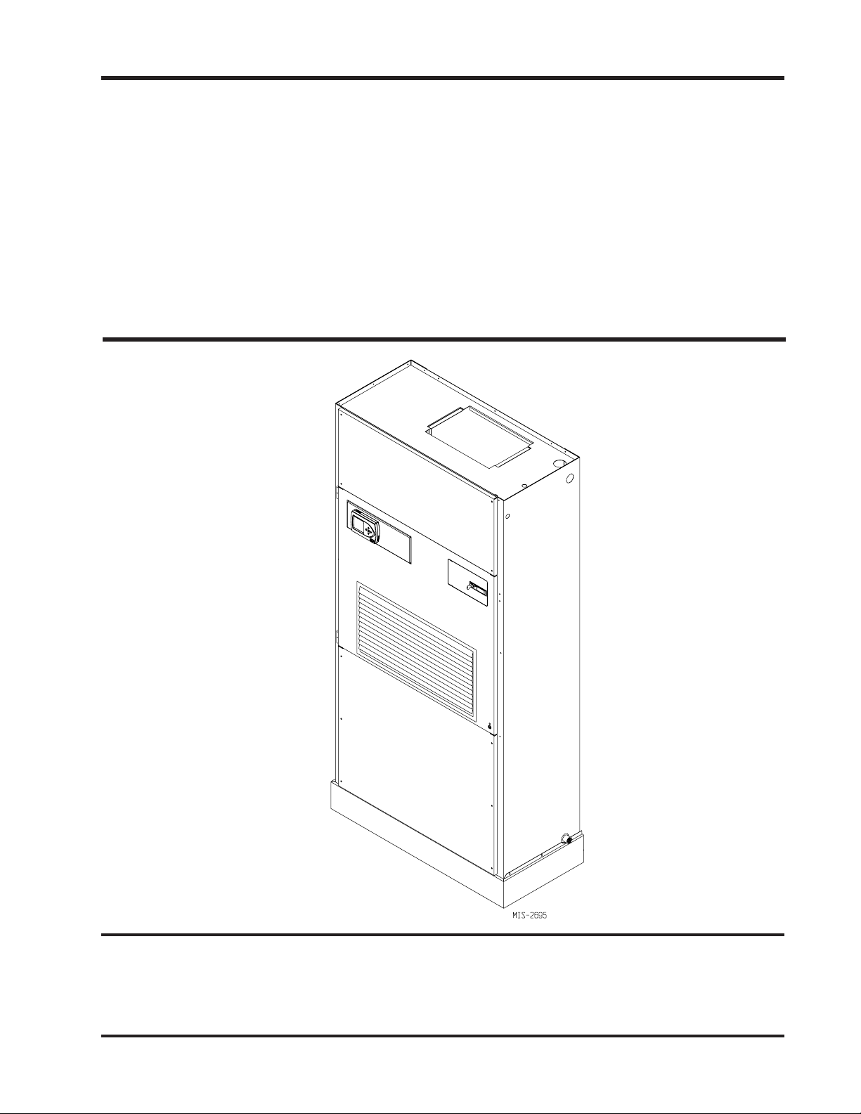
Q-TEC SERIES
PACKAGED
INSTALLATION
INSTRUCTIONS
AIR CONDITIONER
Models:
Q24A1 Q30A1
Q36A1 Q42A1
Q48A1 Q60A1
Bard Manufacturing Company, Inc.
Bryan, Ohio 43506
Since 1914 . . . Moving ahead, just as planned.
Manual: 2100-522B
Supersedes: 2100-522A
File: Vol II Tab 14
Date: 12-15-11
Manual 2100-522B
Page 1 of 38
Page 2

CONTENTS
Getting Other Information and Publications
For more information, contact these publishers: .......... 3
EC General Information
Q-T
Q-TEC Model Nomenclature ......................................... 4
Shipping Damage ......................................................... 8
Unit Removal From Skid .............................................. 8
Handling Unit After Removal From Skid ....................... 9
General ......................................................................... 9
Minimum Installation Height ......................................... 9
Duct Work .................................................................. 11
Filters .......................................................................... 11
Fresh Air Intake .......................................................... 12
Service Light ............................................................... 12
Condensate Drain ...................................................... 12
Optional Rear Drain Kit .............................................. 12
Separate Evaporator Drain Connection ..................... 12
Installation Instructions
Mounting the Unit ....................................................... 19
Wiring — Main Power ................................................. 20
Wiring — Low Voltage Wiring..................................... 20
Low Voltage Connections ........................................... 21
General ....................................................................... 21
Figures
Figure 1 Unit Dimensions .......................................... 7
Figure 2 Air Seal Under Unit ...................................... 8
Figure 3 Removal of Unit From Skid ......................... 8
Figure 4 Unit on Appliance Cart for Moving ............... 9
Figure 5 Installation With Free Blow Plenum .......... 10
Figure 6 Ducted Application ..................................... 10
Figure 7 Supply Duct Connections .......................... 11
Figure 8 Filter Location ............................................ 11
Figure 9 Optional Side Drain ................................... 13
Figure 10 Standard Rear Drain .................................. 13
Figure 11 Rear Drain (Top View) ............................... 13
Figure 12A
Figure 12B
Figure 12C
Figure 12D
Figure 13A
Figure 13B
Figure 14 Removing Locking Screws from Wheels ... 19
Figure 15 Component Location ................................. 20
Figure 16 Thermostat Plug Terminals ........................ 22
Figure 17 Thermostat Wiring Diagram "X" Option .... 23
Figure 18 Thermostat Wiring Diagram "A" Option .... 24
Figure 19 Thermostat Wiring Diagram "D" Option ... 25
Figure 20 Thermostat Wiring Diagram "H" Option ... 26
Figure 21 Fresh Air Damper Removal ....................... 32
Figure 22 QERV Removal ......................................... 33
Figure 23 CO
Figure 24 Control Disassembly ................................. 36
Figure 25 Winding Test .............................................. 36
Figure 26 Drip Loop ................................................... 36
Figure 27 Fan Blade Setting ...................................... 37
Optional Rear Drain Kit ............................. 14
Optional Rear Drain Kit ............................. 15
Optional Rear Drain Kit ............................. 16
Optional Rear Drain Kit ............................. 17
Unit Mounting ............................................ 18
Unit Mounting ............................................ 18
Controller ........................................... 34
2
Start Up
R-410A Refrgerant ......................................................... 27
Topping Off System Charge ........................................... 27
Safety Practices ............................................................. 27
Description of Standard Equipment ............................... 28
Optional CFM (Q36A1, Q42A1, Q48A1 & Q60A1 Only) 28
Important Installer Note.................................................. 28
Phase Monitor ................................................................ 28
Three Phase Scroll Compressor Start Up
Information ....................................................... 28 & 29
Compressor Control Module .......................................... 29
Adjustments ................................................................... 29
Service Hints ......................................................... 29 & 30
Mist Eliminator Service .................................................. 30
Vent Options ......................................................... 30 & 31
Sequence of Operation .................................................. 34
Optional Climate Controls Sequence
of Operation .............................................................. 34
Pressure Service Ports .................................................. 34
Troubleshooting
Troubleshooting GE ECM™ Blower Motors............. 35-36
Fan Blade Setting Dimensions ...................................... 37
Refrigerant Charge ........................................................ 37
Pressure Chart ............................................................... 38
Tables
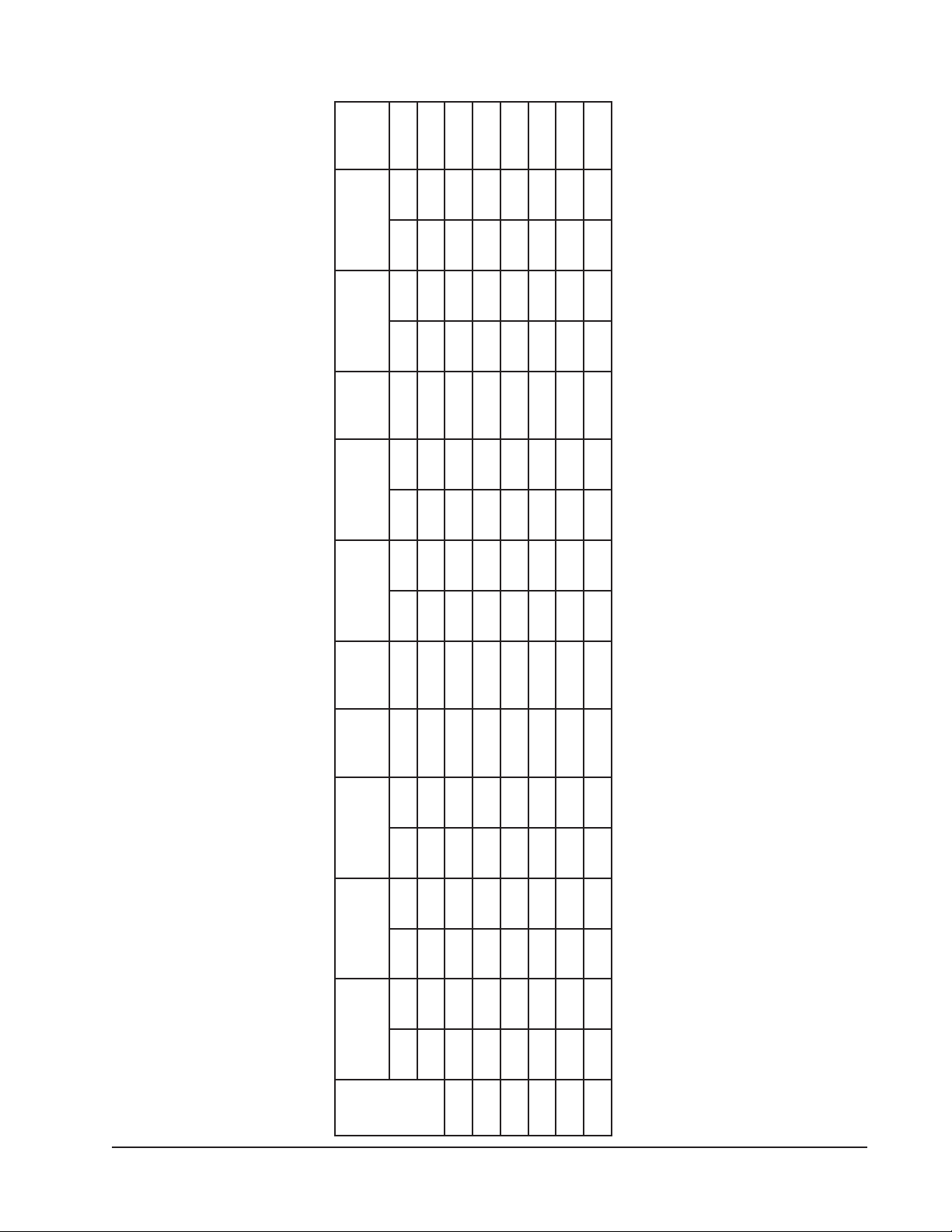
Table 1 Factory Built-In Electric Heat Table .............. 5
Table 2 Electrical Specifications ................................ 6
Table 3 Operating Voltage Range ........................... 20
Table 4 Wall Thermostats ........................................ 22
Table 5 Fan Blade Dimensions ............................... 37
Table 6 Indoor Blower Performance ........................ 37
Table 7 Cooling Pressure ........................................ 38
Manual 2100-522B
Page 2 of 38
Page 3

GETTING OTHER INFORMATION AND PUBLICATIONS
These publications can help you install the air
conditioner or heat pump. You can usually find these at
your local library or purchase them directly from the
publisher. Be sure to consult current edition of each
standard.
National Electrical Code ..................... ANSI/NFPA 70
Standard for the Installation ............. ANSI/NFPA 90A
of Air Conditioning and Ventilating Systems
Standard for Warm Air ...................... ANSI/NFPA 90B
Heating and Air Conditioning Systems
Load Calculation for .......................ACCA Manual J or
Winter and Summer Manual N
Air Conditioning
Low Pressure, Low Velocity ........ ACCA Manual D or
Duct System Design Manual Q
Winter and Summer Air Conditioning
FOR MORE INFORMATION, CONTACT
THESE PUBLISHERS:
ACCA Air Conditioning Contractors of America
1712 New Hampshire Avenue
Washington, DC 20009
Telephone: (202) 483-9370
Fax: (202) 234-4721
ANSI American National Standards Institute
11 West Street, 13th Floor
New York, NY 10036
Telephone: (212) 642-4900
Fax: (212) 302-1286
ASHRAE American Society of Heating, Refrigeration,
and Air Conditioning Engineers, Inc.
1791 Tullie Circle, N.E.
Atlanta, GA 30329-2305
Telephone: (404) 636-8400
Fax: (404) 321-5478
NFPA National Fire Protection Association
Batterymarch Park
P.O. Box 9101
Quincy, MA 02269-9901
Telephone: (800) 344-3555
Fax: (617) 984-7057
Manual 2100-522B
Page 3 of 38
Page 4
Q-T
EC
Series General Information
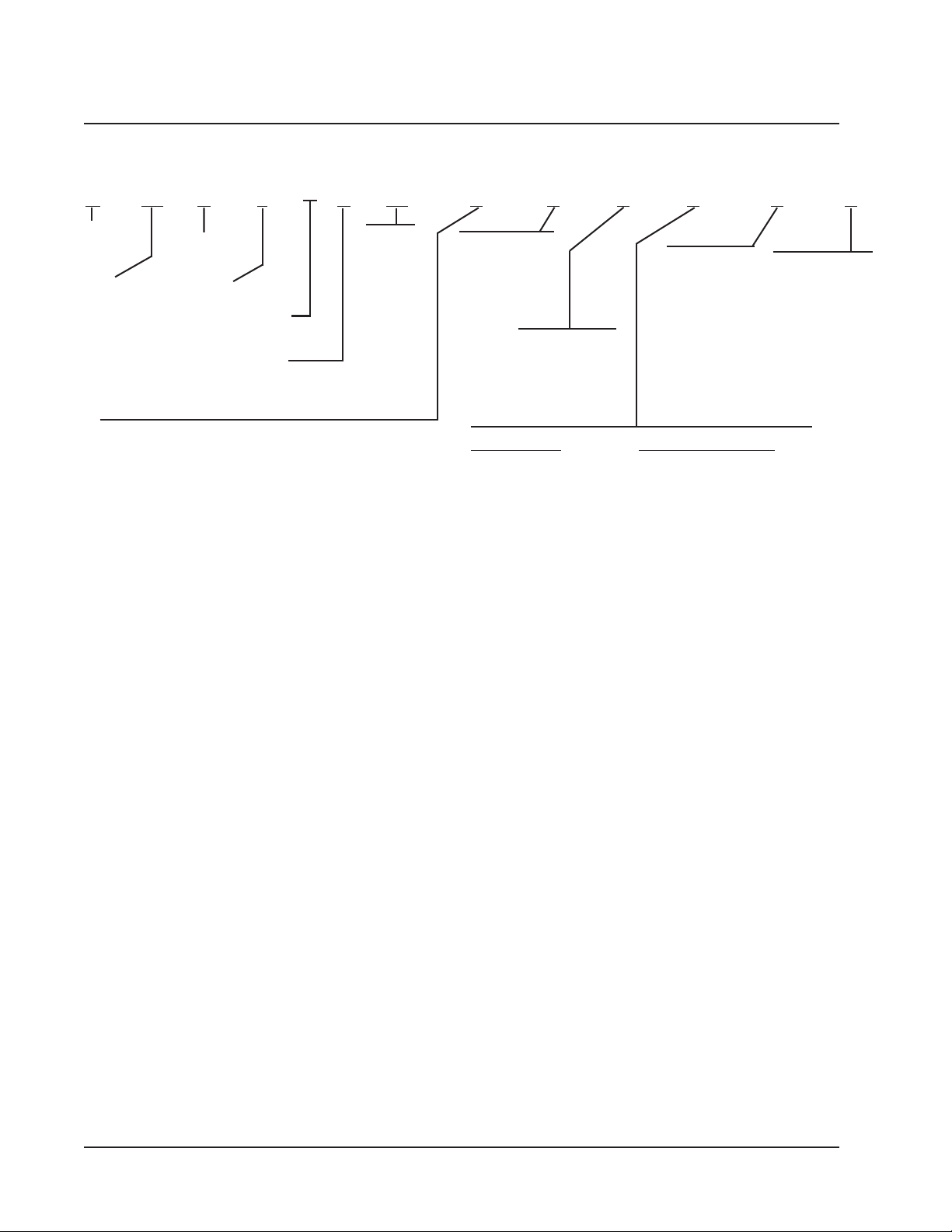
Q-TEC MODEL NOMENCLATURE
Q 42 A 1 A 10 X X V X X X
MODEL
NUMBER
Q-Tec™
CAPACITY
24 - 2 Ton
30 - 2½ Ton
36 - 3 Ton
42 - 3½ Ton
48 - 4 Ton
60 - 5 Ton
VENTILATION OPTIONS
X - Barometric Fresh Air Damper (Standard)
B - Blank-off Plate
E - Economizer (Not available on dehumidification versions)
P - Commercial Ventilator - Motorized w/Exhaust Power Return
V - Commercial Ventilator - Motorized w/Exhaust Spring Return
R - Energy Recovery Ventilator w/Independent Intake & Exhaust Control
NOTE: 1 Insert “D” for dehumidification with hot gas reheat. Reference 7960-584 for complete details.
2 If “X” control option is selected, then thermostat and humidistat, if applicable, or DDC control system must be field supplied.
AIR
CONDITIONER
REVISION |
SPECIALTY
PRODUCTS 1 |
(Non-Standard)
VOLTS & PHASE |
A - 230/208/60/1
B - 230/208/60/3
C - 460/60/3
KW
0Z - 0KW
05 - 5KW
06 - 6KW
09 - 9KW
10 -10KW
12 -12KW
15 -15KW
FILTER OPTIONS
X - 1 inch Fiberglass
(Standard)
F - 2 inch Fiberglass
P - 2 inch Pleated
COLOR
V - Platinum w/Slate
Front (Vinyl)
X - Beige paint
4 - Gray paint
STANDARD UNITS DEHUMIDIFICATION UNITS
X - None 2 X - None 2
A - Electronic/Non Prog E - Electronic/Prog/Humidistat
D - Electronic/Prog G - Electronic Non-Prog/Humidistat
H - Electronic/Prog/CO
CLIMATE CONTROL2
2
COIL OPTIONS
X -Standard
1 -Phenolic coated
evaporator*
2 -Phenolic coated
condenser
3 -Phenolic coated
evaporator and
condenser coil*
*and reheat if
applicable
I - Electronic Prog/Humidistat/CO
INTERNAL
CONTROLS
X - Standard
• High Pressure
Switch
• Low Pressure
Switch
• Compressor
Control Module
w/Time Delay
J - Alarm Relay +
LAC + Above
2
Manual 2100-522B
Page 4 of 38
Page 5
C-1A63Q
C-1A24Q
C-1A84QA-1A06QB-1A06QC-1A06Q
B-1A63Q
B-1A24Q
B-1A84Q
A-1A63Q
A-1A24Q
A-1A84Q
TABLE 1
FACTORY BUILT-IN ELECTRIC HEAT TABLE
A-1A42Q
A-1A03QB-1A42QB-1A03QC-1A42QC-1A03Q
1-V0421-V8021-V0421-V8021-V0421-V8023-V0843-V0841-V0421-V8021-V0421-V8023-V0841-V0421-V8021-V0421-V8023-V084
sledoM
0.5083,61092,21 083,61092,21
WKHUTBHUTBHUTBHUTBHUTBHUTBHUTBHUTBHUTBHUTBHUTBHUTBHUTBHUTBHUTBHUTBHUTBHUTB
0.9007,03000,32007,03000,32007,03007,03007,03000,32007,03007,03000,32007,03
0.6005,02063,51005,02063,51005,02005,02005,02063,51005,02
0.21000,14007,03000,14
0.01076,23075,42 076,23075,42076,23075,42
0.51 051,94068,63051,94068,63051,94051,94068,63051,94068,63051,94
Manual 2100-522B
Page 5 of 38
Page 6

TABLE 2
ELECTRICAL SPECIFICATIONS
tiucriCelgniS tiucriClauD
detaR
ledoM
Z0A-1A42Q
50A
01A
Z0B-1A42Q
60B
90B
Z0C-1A42Q
60C
90C
Z0A-1A03Q
50A
01A
Z0B-1A03Q
60B
90B
21B
Z0C-1A03Q
60C
90C
21C
Z0A-1A63Q
50A
01A
51A
Z0B-1A63Q
60B
90B
51B
Z0C-1A63Q
60C
90C
51C
Z0A-1A24Q
50A
01A
51A
Z0B-1A24Q
60B
90B
51B
Z0C-1A24Q
60C
90C
51C
Z0A-1A84Q
50A
01A
51A
Z0B-1A84Q
60B
90B
51B
Z0C-1A84Q
60C
90C
51C
Z0A-1A06Q
01A
51A
Z0B-1A06Q
90B
51B
Z0C-1A06Q
90C
51C
stloV
esahPdna
1-802/032
3-802/032
3-064
1-802/032
3-802/032
3-064
1-802/032
3-802/032
3-064
1-802/032
3-802/032
3-064
1-802/032
3-802/032
3-064
1-802/032
3-802/032
3-064
3 muminiM
dleiF.oN
rewoP
stiucriC
1
1
1
1
1
1
1
1
1
1
1
1
1
1
1
1
1
1
1
1
1
1
1
2ro1
1
1
1
1
1
1
1
1
1
1
1
2ro1
1
1
1
1
1
1
1
1
1
1
1
2ro1
1
1
1
1
1
1
1
1
1
1
2ro1
1
1
1
1
1
1
1 mumixaM
tiucriC
yticapmA
22
03
55
71
52
33
01
21
71
52
23
75
81
52
43
34
11
41
81
32
92
43
85
48
12
62
53
35
21
41
81
72
53
53
85
38
62
62
53
35
31
41
81
72
73
73
85
38
82
82
53
35
41
41
81
72
54
95
48
13
63
55
61
91
82
2 dleiF
esuFlanretxE
.rkrB.tkCro
03
03
06
02
52
53
51
51
02
53
53
06
52
52
53
54
51
51
02
52
54
54
06
09
03
03
53
06
51
51
02
03
05
05
06
09
53
53
53
06
51
51
02
03
05
05
06
09
04
04
04
06
02
02
02
03
06
06
09
54
54
06
02
02
03
2 dnuorG
rewoP
eziSeriW
01
01
6
21
01
8
41
41
21
8
8
6
01
01
8
6
41
41
21
01
8
8
6
4
01
01
8
6
41
41
21
01
8
8
6
4
8
8
8
6
41
41
21
01
8
8
6
4
8
8
8
6
21
21
21
01
8
6
4
8
8
6
21
21
01
8
8
8
8
8
8
3 muminiM
tiucriC
eriW
01
01
01
21
01
01
41
41
21
01
01
01
01
01
01
01
41
41
21
01
01
01
01
01
01
01
41
41
21
01
01
01
01
01
01
01
41
41
21
01
01
01
01
01
01
01
01
21
21
21
01
01
01
01
01
01
21
21
01
yticapmA
A.tkC B.tkC A.tkC B.tkC A.tkC B.tkC A.tkC B.tkC
-
-
-
-
-
-
-
-
-
-
-
-
-
-
-
-
-
-
-
-
-
-
85
-
-
-
-
-
-
-
-
-
-
85
-
-
-
-
-
-
-
-
-
-
85
-
-
-
-
-
-
-
-
-
95
-
-
-
-
-
-
1 mumixaM
esuFlanretxE
-
-
-
-
-
-
-
-
-
-
-
-
-
-
-
-
-
-
-
-
-
-
-
52
-
-
-
-
-
-
-
-
-
-
52
-
-
-
-
-
-
-
-
-
-
52
-
-
-
-
-
-
-
-
-
52
-
-
-
-
-
-
-
-
-
-
-
-
-
-
-
-
-
-
-
-
-
-
-
-
-
-
-
-
-
-
-
-
-
-
-
-
-
-
-
-
-
-
-
-
-
-
-
-
-
-
-
06
52
-
-
-
-
-
-
-
-
-
-
-
-
-
-
-
-
-
-
-
-
-
-
06
52
-
-
-
-
-
-
-
-
-
-
-
-
-
-
-
-
-
-
-
-
-
-
06
52
-
-
-
-
-
-
-
-
-
-
-
-
-
-
-
-
-
-
-
-
06
52
-
-
-
-
-
-
-
-
-
-
-
-
2 dleiF
rekaerB.tkCro
rewoP
eziSeriW
-
-
-
-
-
-
-
-
-
-
-
-
-
-
-
-
-
-
-
-
-
-
-
-
-
-
-
-
-
-
-
-
-
-
-
-
-
-
-
-
-
-
-
-
-
-
6
01
-
-
-
-
-
-
-
-
-
-
-
-
-
-
-
-
-
-
-
-
-
-
6
01
-
-
-
-
-
-
-
-
-
-
-
-
-
-
-
-
-
-
-
-
-
-
8
01
-
-
-
-
-
-
-
-
-
-
-
-
-
-
-
-
-
-
-
-
8
01
-
-
-
-
-
-
-
-
-
-
-
-
1 Maximum size of the time delay fuse or HACR type circuit breaker for protection of field wiring conductors.
2 Based on 75°C copper wire. All wiring must conform to the National Electrical Code and all local codes.
3 These “Minimum Circuit Ampacity” values are to be used for sizing the field power conductors. Refer to the National Electric
Code (latest revision), article 310 for power conductor sizing.
CAUTION: When more than one field power conductor circuit is run through one conduit, the conductors must be derated.
Pay special attention to Note 8 of Table 310 regarding Ampacity Adjustment Factors when more than three
conductors are in a raceway.
-
-
-
-
-
-
-
-
-
-
-
-
-
-
-
-
-
-
-
-
-
-
-
-
-
-
-
-
-
-
-
-
-
-
-
-
-
-
-
-
-
-
-
-
-
-
-
-
-
-
-
-
-
-
-
-
-
-
-
-
-
2 dnuorG
01
01
01
01
eziSeriW
-
-
-
-
-
-
-
-
-
-
-
-
-
-
-
-
-
-
-
-
-
-
01
-
-
-
-
-
-
-
-
-
-
01
-
-
-
-
-
-
-
-
-
-
01
-
-
-
-
-
-
-
-
-
01
-
-
-
-
-
-
Manual 2100-522B
Page 6 of 38
Page 7
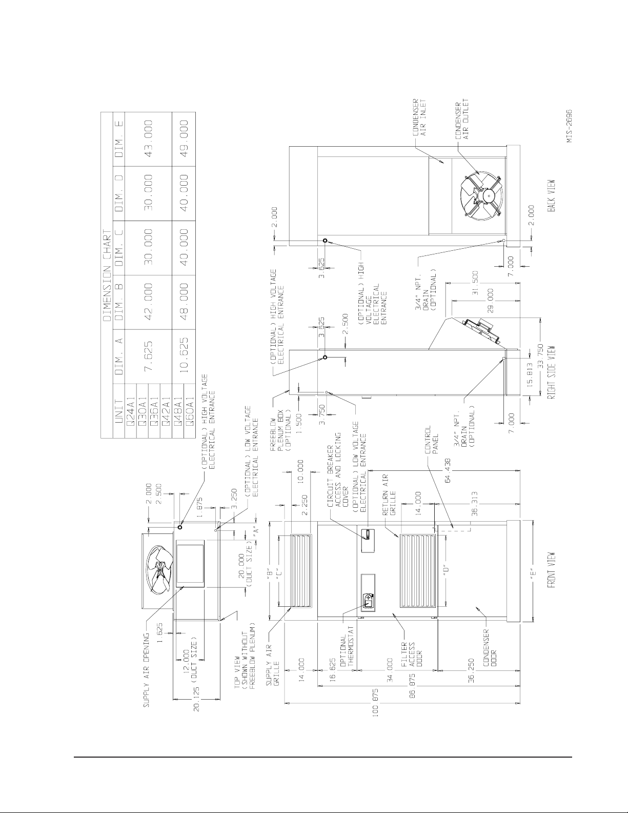
FIGURE 1
UNIT DIMENSIONS
Manual 2100-522B
Page 7 of 38
Page 8
SHIPPING DAMAGE
Upon receipt of equipment, the carton should be
checked for external signs of shipping damage. The
skid must remain attached to the unit until the unit is
ready for installation. If damage is found, the receiving
party must contact the last carrier immediately,
preferably in writing, requesting inspection by the
carrier’s agent.
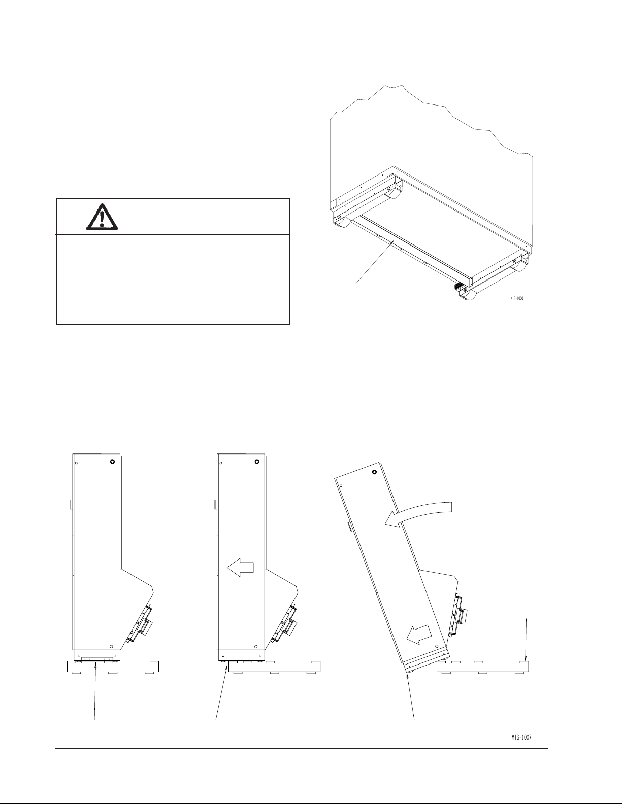
UNIT REMOVAL FROM SKID
WARNING
This unit is heavy and requires more than one
person to handle and remove from the skid.
Check unit wheels to ensure that wheels are
locked before removing from skid. Extreme
caution must be taken to prevent injury to
personnel and damage to the unit.
It is recommended that the unit not be removed from the
skid with a forklift since the air seal under the unit could
be damaged. See Figure 2.
The shipping brackets on each side of the unit must be
removed and discarded. See Figure 3-A. The return air
grille panel can be removed to provide a place to hold
FIGURE 2
AIR SEAL UNDER QT
Air Seal
the unit. The unit can be slid forward on the skid until
the front wheels hang over the edge of the skid. See
Figure 3-B. The unit can be tipped forward and slid
down the edge of the skid until the front wheels touch
the ground. See Figure 3-C. The wheels will not roll.
They are shipped from the factory locked so they will
not roll. The back of the skid will have to be held down
to keep it from tipping up. The skid can be slid out from
under the unit. The unit can then be set upright.
EC
UNIT
FIGURE 3
REMOVAL OF UNIT FROM SKID
Hold Skid
Down
A Shipping Brackets B Front Wheels Over Edge
Manual 2100-522B
Page 8 of 38
C Front Wheels On Floor
Page 9
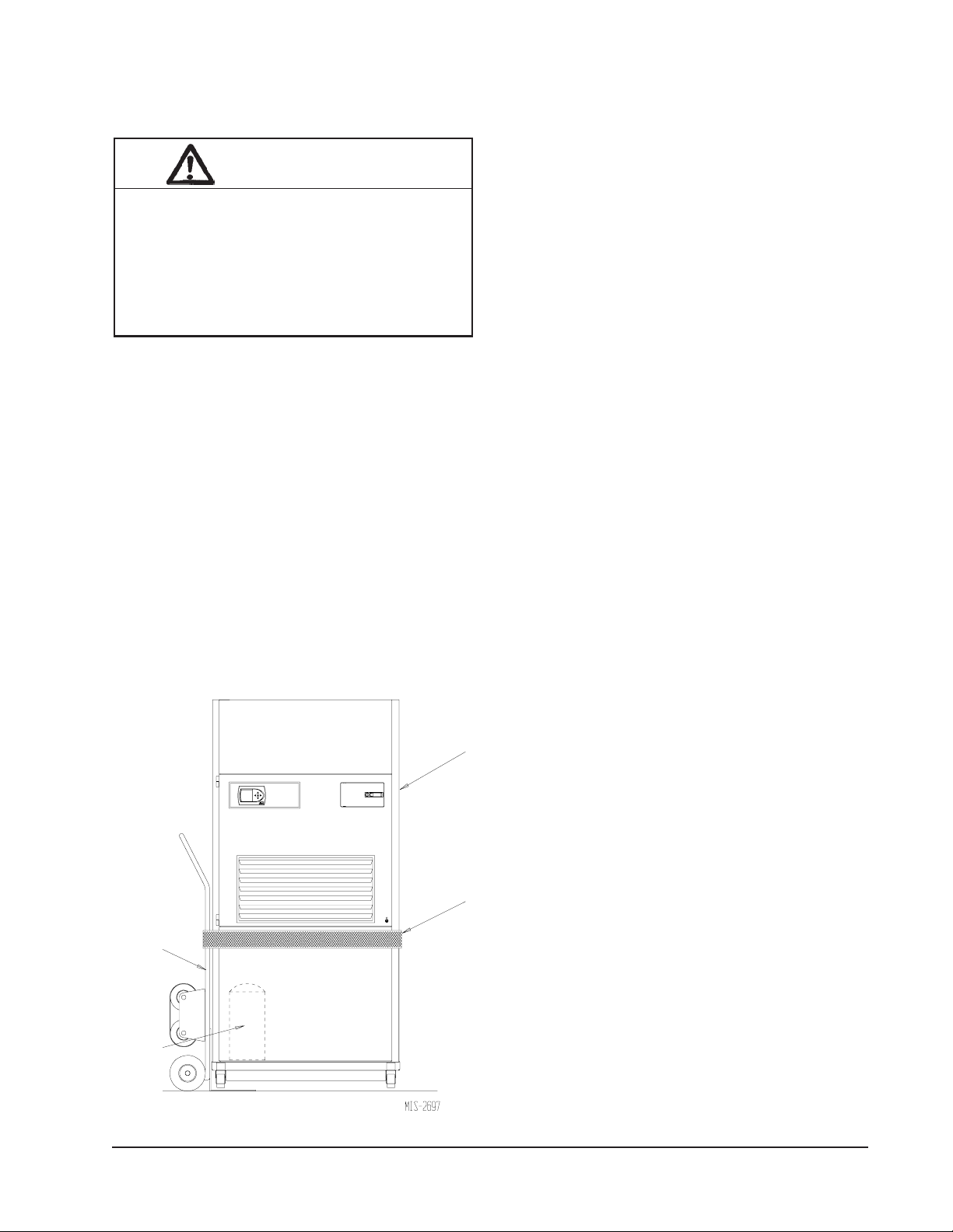
HANDLING UNIT AFTER REMOVAL
FROM SKID
WARNING
Exercise extreme caution when pushing the
unit on the rollers. Handle and push from the
lower 1/3 of the unit. Insure that debris is not
on the floor where the unit is to be moved on
the rollers. Failure to do so could result in the
unit tipping over and causing bodily injury and/
or damage to the unit.
The unit will have to be turned sideways and removed
from the skid to fit through a 36" doorway. If the door
height allows, the unit can be slid sideways through the
door.
If the unit can not be slid through the door, then the unit
will have to be put on a cart and tipped down to roll
through the door. It is recommended that an appliance
cart by used with a strap to hold the unit on the cart.
The wheels of the unit must be locked. If the wheels
were allowed to roll, the unit could roll off the cart. The
unit should always be carted from the left side. This is
the side where the compressor is located. See Figure 4.
The blade of the appliance cart should be slid under the
wheels of the unit. The strap of the appliance cart
should be placed around the unit and strapped tightly.
Help will be required to tip the unit back onto the cart.
The unit can be leaned far enough back to be rolled
through the door. Be careful when setting the unit back
up to keep from damaging the unit.
GENERAL
The equipment covered in this manual is to be installed
by trained, experienced service and installation
technicians. A QWS-Series wall sleeve supplied as a
separate accessory must be ordered and installed with
Q-Tec unit.
The unit is designed for use with or without duct work.
For use without duct work, Plenum Box QPB42 is
recommended.
These instructions explain the recommended method to
install the air cooled self-contained unit and the
electrical wiring connections to the unit.
These instructions and any instructions packaged with
any separate equipment required to make up the entire
air conditioning system should be carefully read before
beginning the installation. Note particularly “Start
Procedure” and any tags and/or labels attached to the
equipment.
APPLIANCE
CART
COMPRESSOR
FIGURE 4
UNIT ON APPLIANCE CART
Q-TEC UNIT
(Right Side)
STRAP
While these instructions are intended as a general
recommended guide, they do not supersede any national
and/or local codes in any way. Authorities having
jurisdiction should be consulted before the installation is
made. See Page 3 for information on codes and
standards.
Size of unit for a proposed installation should be based
on heat loss calculation made according to methods of
Air Conditioning Contractors of America (ACCA). The
air duct should be installed in accordance with the
Standards of the National Fire Protection Systems of
Other Than Residence Type, NFPA No. 90A, and
Residence Type Warm Air Heating and Air
Conditioning Systems, NFPA No. 90B. Where local
regulations are at a variance with instructions, installer
should adhere to local codes.
MINIMUM INSTALLATION HEIGHT
The minimum installation height of the unit with a Free
Blow Plenum is 8 ft. 6 in. This provides enough
clearance for the plenum to be removed. See Figure 5.
The minimum installation height for ducted applications
is 8 ft. 4½ in. This provides enough clearance to install
the duct work. See Figure 6.
Manual 2100-522B
Page 9 of 38
Page 10
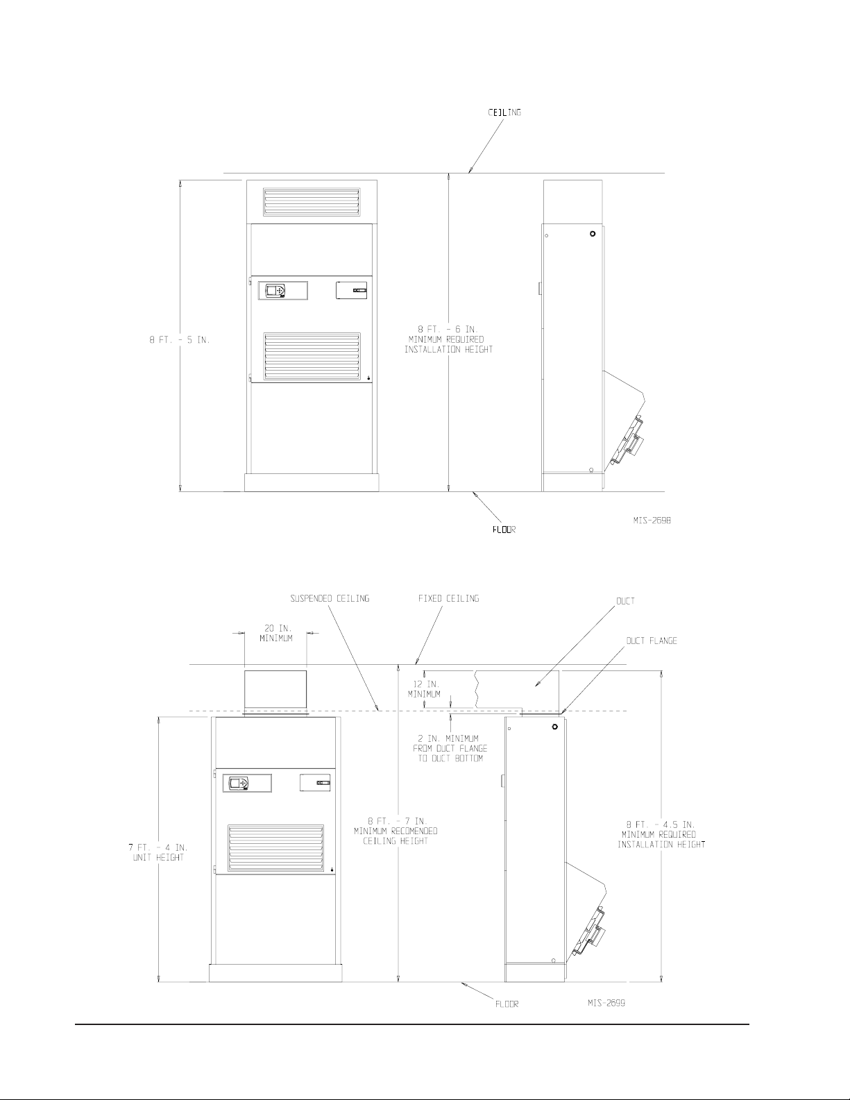
FIGURE 5
INSTALLATION WITH FREE BLOW PLENUM
FIGURE 6
DUCTED APPLICATION
Manual 2100-522B
Page 10 of 38
Page 11
DUCT WORK
All duct work must be properly sized for the design
airflow requirement of the equipment. Air Conditioning
Contractors of America (ACCA) is an excellent guide to
proper sizing. All duct work or portions thereof not in
the conditioned space should be properly insulated in
order to both conserve energy and prevent condensation
or moisture damage. When duct runs through unheated
spaces, it should be insulated with a minimum of one
inch of insulation. Use insulation with a vapor barrier
on the outside of the insulation. Flexible joints should
be used to connect the duct work to the equipment in
order to keep the noise transmission to a minimum.
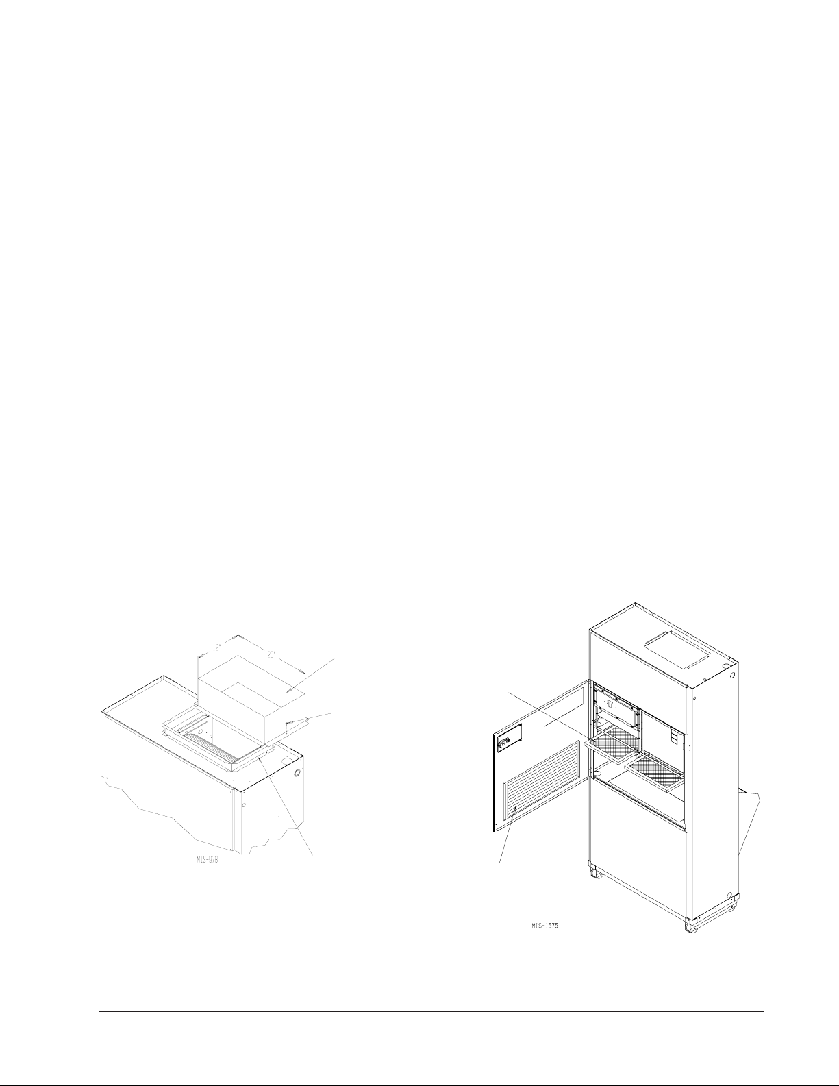
The Q-TEC series unit has provision to attach a supply
air duct to the top of the unit. Duct connection size is 12
inches x 20 inches. The duct work is field supplied and
must be attached in a manner to allow for ease of
removal when it becomes necessary to slide the unit out
from the wall for service. See Figure 7 for suggested
attachment method.
The Q-T
return (non-ducted) and either free blow with the use of
QPB Plenum Box or a duct supply air system.
The QPB and QPBHW Plenum Box mounts on top of
the unit and has both vertically and horizontally
adjustable louvers on the front discharge grille.
For hot water coil option a QPBHWxx-F for free blow
or QPBHWxx-D for ducted airflow is used.
EC
series units are designed for use with free
When used with a ducted supply, a QCX Cabinet
Extension can be used to conceal the duct work above
the unit to the ceiling. This extends 20" above the unit
for a total height above the floor of 10'-7/8". The unit is
equipped with a variable speed indoor blower motor
which increases in speed with an increase in duct static
pressure. The unit will therefore deliver proper rated
airflow up to the maximum ESP shown in Table 7.
However, for quiet operation of the air system, the duct
static should be kept as low as practical, within the
guidelines of good duct design.
FILTERS
Two 1-inch throw away filters [(1) 16x16 and (1)
16x20] are supplied with each unit. The filters slide into
filter brackets. Refer to Figure 8.
The filters are serviced from the inside of the building
by opening the hinged door. This door is attached by a
screw and one locking latch.
The internal filter brackets are adjustable to
accommodate 2-inch filters. The tabs for the 1-inch
filters must be bent down to allow the 2-inch filters to
slide in place.
FIGURE 7
SUPPLY DUCT CONNECTIONS
SUPPLY DUCT
TO BE FIELD
SUPPLIED
ATTACHMENT
SCREWS TO
BE FIELD
SUPPLIED
ROOM SIDE OF
EC UNIT
Q-T
DUCT FLANGE
PROVIDED WITH
UNIT
NOTE: Unit cabinet, supply air duct and free blow
plenum are approved for “0” clearance to
combustible material.
FILTERS
RETURN AIR
GRILLE
FIGURE 8
FILTER LOCATION
Manual 2100-522B
Page 11 of 38
Page 12

FRESH AIR INTAKE
This unit is equipped with a fresh air damper assembly.
The damper blade is locked in the closed position when
the unit is shipped from the factory. To allow the
damper to operate remove the two plastic locking pins,
one on each end of the blade. This will allow for
maximum fresh airflow. The damper blade will now
open when the indoor blower is operating. If less than
maximum fresh airflow is required, reinsert the plastic
pins to limit damper blade opening to desired level.
Two extra pins are provided (taped to the inside of the
assembly) which may be used to hold the blade in some
position other than minimum or maximum position.
This fresh air assembly is located in the rear of the unit
and to gain access to make these adjustments remove
the air filter service door.
All capacity, efficiency and cost of operation
information as required for Department of Energy
“Energyguide” Fact Sheets are based upon the fresh air
blank-off plate in place and is recommended for
maximum energy efficiency.
The blank-off plate is available upon request from the
factory and is installed in place of the fresh air damper
shipped with each unit.
For details on energy recovery ventilation see separate
section.
SERVICE LIGHT
The unit is equipped with a service light, which signals
the user that service is required. The light is located in
the upper control panel and is visible only when the
hinged service/filter access door is open.
The Service Unit light indicates that the unit has been
shut off by a high or low pressure device. This indicates
that the unit needs to be serviced.
CONDENSATE DRAIN
There are two drain connections on the unit. The rear
drain is the primary drain, and is located on the right
lower rear panel of the unit. The optional side drain is
located on the bottom right side of the unit. The side
drain is shipped with a plug installed.
The side drain requires a water trap for proper drainage.
See Figure 9. The drain can be routed through the floor
or through the wall. If the drain is to be routed through
an unconditioned space, it must be protected from
freezing. The drain line must be able to be removed
from the unit if it is necessary to remove the unit from
the wall. When the side drain is used, the plug must be
removed and installed in the rear drain outlet.
The rear drain can be used with wall thickness of up to
10 inches where a water trap can be installed between
the unit and the interior wall. See Figure 10. The trap
cannot extend beyond the edge of the unit or it will
interfere with the wall mounting bracket. The drain can
be routed through the floor or through the wall. If the
drain is routed through the wall, the drain line must be
positioned such that it will not interfere with the sleeve
flange or the grille. See Figure 11. If the drain is to be
routed through an unconditioned space, it must be
protected from freezing.
OPTIONAL REAR DRAIN KITS
Optional Rear Drain Kit, Bard Model QCDS48A, is also
available for these products. The optional rear drain kit
offers multiple benefits that include the following:
• Allows unit to be rolled away from the sleeve
without having to disconnect any hard plumbing
connections.
• Allows indoor coil condensate to be easily
connected to Rear Drain Box while bypassing the
outdoor coil drain pan. This aids in minimizing the
potential for biological growth to occur by
minimizing the standing water and exposing it to
warm temperatures.
See Figures 12A, 12B, 12C and 12D.
The drain box permanently mounts onto the wall sleeve
and is then either piped directly outdoors, or can be
piped vertically. The Q-Tec unit is then equipped with
fittings on the rear of the unit that slide into the drain
box as it is wheeled towards the wall sleeve.
NOTE: On models equipped with a refrigerant
subcooler in the lower drain pan may experience a 23% decrease in cooling performance and efficiency
when the indoor condensate is routed around the
outdoor coil drain pan/subcooler assembly. Unit rated
performance and efficiency are with the indoor
condensate routed to the outdoor coil pan.
There is also a heated version of the rear drain box
available (Model #QCDS48H) for installation in
northern climates where freezing may occur.
SEPARATE EVAPORATOR DRAIN
CONNECTION (OPTIONAL)
A knockout is provided in the back right corner of the
units for use when draining the evaporator drain pan
separately from the condenser. This knockout is 5 inches
above the back condenser drain opening. To utilize a
separate evaporator drain connection remove the
knockout and route the existing evaporator drain hose out
this knockout and then to an appropriate drain line.
Manual 2100-522B
Page 12 of 38
Page 13

FIGURE 9
OPTIONAL SIDE DRAIN (SIDE VIEW) INSTALLATION
Q-TEC UNIT
FIGURE 10
STANDARD REAR DRAIN
SLEEVE
WATER
TRAP
FIGURE 11
REAR DRAIN (TOP VIEW)
WALL (MAXIMUM
10" FOR REAR
DRAIN)
DRAIN LINE
COUPLINGS NOT
SHOWN BUT
RECOMMENDED
FOR EASE OF
REMOVABILITY
FOR SERVICE.
WALL
BRACKET
UNIT
Manual 2100-522B
Page 13 of 38
Page 14

WALL SLEEVE
MIS-2469
FIGURE 12A
OVERFLOW TUBE
CAULK AROUND TUBE
DRAIN BOX
Manual 2100-522B
Page 14 of 38
Page 15

PLUG INSTALLED IN
SIDE Q/Tec DRAIN
FIGURE 12B
REAR DRAIN CONNECTION IN
Q/Tec PRODUCT
3/4" PLASTIC PIPE NIPPLE
SUPPLIED WITH DRAIN BOX KIT
(APPLY TEFLON TAPE TO
THREADS)
IMPORTANT !
1/2" SLIP X 1/2" SLIP X 3/4" NPT
TEE SUPPLIED WITH DRAIN BOX KIT
(TIGHTEN THREADS SO TEE IS
HORIZONTAL TO FLOOR)
MIS-2470
Manual 2100-522B
Page 15 of 38
Page 16

FIGURE 12C
REMOVE KNOCK-OUT FOR
INDOOR DRAIN HOSE CONNECTOR
(If Used)
Manual 2100-522B
Page 16 of 38
MIS-2471
Page 17

FIGURE 12D
DRAIN HOSE FROM INDOOR
DRAIN PAN.
MOVE HOSE FROM ATTACHMENT IN
LOWER DRAIN PAN AND SLIDE ONTO
DRAIN BOX BARB FITTING, SECURING
WITH SUPPLIED CLAMP IF OUTDOOR
PAN IS BYPASSED. ( WILL REDUCE RISK
OF ALGAE GROWTH IN THE OUTDOOR
PAN BUT AT A SLIGHT COOLING
PERFORMANCE REDUCTION OF 2-3% )
MIS-2472
Manual 2100-522B
Page 17 of 38
Page 18

BOTTOM
TRIM PIECE
BOTTOM TRIM
EXTENSION
FIGURE 13A
UNIT MOUNTING
SIDE TRIM
(2 PCS.)
SIDE TRIM
(2 PCS.)
MOUNTING
BRACKET
#8 SCREW
PROVIDED
(LIGHT COLOR)
CABINET
SIDE PANEL
ENLARGED VIEW OF MOUNTING
BRACKET SHOWING SLEEVE TO
CABINET ATTACHMENT
MOUNTING BRACKET
WALL
SLEEVE
#10 HEX
HEAD SCREW
PROVIDED
Sleeve
Washer
FIGURE 13B
UNIT MOUNTING
Return Grille
Stud
Nut
Condenser
Door (Removed)
MIS-2689
Lower Control Panel
Manual 2100-522B
Page 18 of 38
Page 19

INSTALLATION INSTRUCTIONS
MOUNTING THE UNIT
When installing a Q-TEC unit near an interior wall on the
left side, a minimum of 8 inches is required; 12 inches is
preferred.
When installing a Q-TEC unit near an interior wall on the
right side, a minimum of 18 inches is required as
additional space is required to connect the side drain. If
the rear condensate drain kit QCDS48 is used the
minimum can be reduced to 8 inches.
This clearance is required to allow for the attachment of
the unit to the sleeve and side trim pieces to the wall.
This unit is to be secured to the wall sleeve with
mounting brackets provided. The unit itself, the supply
duct and the free blow plenum are suitable of “0”
clearance to combustible material.
Following are the steps for mounting the Q-T
reference see Figure 13A for external mounting bracket
or 13B for internal bolt secured bracket (recommended).
1. Attach mounting brackets to the wall sleeve with
screws provided. Either use external mounting
bracket (Fig. 13A) or internal bolt bracket (Fig. 13B).
2. Position the unit in front of the sleeve with the
condenser section toward the sleeve.
3. Remove the locking screws from the wheels.
Refer to Figure 14.
4. Roll the unit into the sleeve. Make sure to check
both sides of the unit as it is being rolled to keep
it centered in the sleeve. Also check the
EC
. For
alignment to the mounting brackets. This unit
must be level from side to side. If adjustments
are necessary, shim up under the rollers with
sheets of steel or any substance that is not
affected by moisture.
5. Make sure the gasket on the rear of the unit is
touching the sleeve across the top and down both
sides. This is a rain water seal.
6. Secure the mounting brackets to the unit with
screws provided, #10 hex head sheet metal
screws (Figure 13A) or use nut and washer to
secure sleeve (Figure 13B).
7. Bottom trim extensions are provided for use when
wall is less than 14 inches but greater than 10.5
inches. Secure to wall with screws (not provided).
8. Attach the bottom trim piece to the unit with the
screws provided (dark colored).
9. Position side trim pieces to wall and attach with
field supplied screws. There are two long pieces
and two short pieces supplied. The long pieces
are to enclose the gap behind the unit. The short
pieces are to fill the gap behind the cabinet
extension or the free blow plenum box. They
may be cut to suit your ceiling height or overlap
the unit side trim. There is sufficient length to
trim up to a 10'2" ceiling.
NOTE: If the exterior wall thickness is between 5
inches to 10.5 inches, a side trim extension
piece kit, model QSTX42, is available.
REMOVING LOCKING SCREWS FROM WHEELS
REMOVE SCREWS FROM WHEELS
BEFORE ROLLING INTO PLACE
FIGURE 14
Manual 2100-522B
Page 19 of 38
Page 20

WIRING – MAIN POWER
Refer to the unit rating plate and/or Table 2 for wire
sizing information and maximum fuse or “HACR Type”
circuit breaker size. Each unit is marked with a
“Minimum Circuit Ampacity”. This means that the
field wiring used must be sized to carry that amount of
current. Depending on the installed KW of electric
heat, there may be two field power circuits required. If
this is the case, the unit serial plate will so indicate. All
models are suitable only for connection with copper
wire. Each unit and/or wiring diagram will be marked
“Use Copper Conductors Only”. These instructions
MUST BE adhered to. Refer to the National Electrical
Code (NEC) for complete current carrying capacity data
on the various insulation grades of wiring material. All
wiring must conform to NEC and all local codes.
The electrical data lists fuse and wire sizes (75°C
copper) for all models, including the most commonly
used heater sizes. Also shown are the number of field
power circuits required for the various models with
heaters.
The unit rating plate lists a “Maximum Time Delay
Relay Fuse” or “HACR Type” circuit breaker that is to
be used with the equipment. The correct size must be
used for proper circuit protection, and also to assure that
there will be no nuisance tripping due to the momentary
high starting current of the compressor motor.
The disconnect access door on this unit may be locked
to prevent unauthorized access to the disconnect.
See “Start Up” section for information on three phase
scroll compressor start-ups.
The field wiring connections are located behind the top
and hinged panel in the circuit breaker panel. See
Figure 15.
WIRING – LOW VOLTAGE WIRING
230/208V, 1 PHASE AND 3 PHASE EQUIPMENT
DUAL PRIMARY VOLTAGE TRANSFORMERS.
All Equipment leaves the factory wired on 240V tap.
For 208V operation, reconnect from 240V to 208V tap.
The acceptable operating voltage range for the 240 and
208V taps are as noted in Table 3.
TABLE 3
OPERATING VOLTAGE RANGE
PATEGNAR
V042612–352
V802781–022
NOTE: The voltage should be measured at the field
power connection point in the unit and while
the unit is operating at full load (maximum
amperage operating condition).
ELECTRIC
HEATERS
UNIT
MOUNTED
THERMOSTAT
LOCATION
DEHUMIDIFICATION
CONTROL
(OPTIONAL)
FIGURE 15
COMPONENT LOCATION
SIDE FIELD WIRE
ENTRANCE
REMOTE
THERMOSTAT
TERMINAL
BLOCK
I
NDOOR
BLOWER
CIRCUIT
BREAKER PANEL
& CONTROLS
LOWER
CONTROL
PANEL
The standard Climate Control Option X is a remote
thermostat connection terminal block. See Figure 17 for
wiring diagram. Compatible thermostats are listed in
Table 4.
The Climate Control Option A is an electronic, nonprogrammable manual or auto changeover thermostat.
The subbase of the thermostat is factory wired to the
front panel of the unit. See Figure 18 for wiring
diagram. Compatible for use with Bard CS2000A*
Controller and Energy Recovery Ventilator.
The Climate Control Option D is an electronic,
programmable thermostat. The subbase of the
thermostat is factory wired to the front panel of the unit.
See Figure 19 for wiring diagram. Compatible for use
with Energy Recovery Ventilator or Economizer.
The Climate Control Option H is an electronic,
programmable thermostat and a CO2 controller. The
subbase of the thermostat and CO2 controller are factory
wired to the front panel of the unit. See Figure 20 for
wiring diagram.
NOTE: On option X or A the CS2000A* (or other field
provided means to control ventilation) must be
used if any of the motorized ventilation options
are installed.
NOTE: Thermostats are shipped in the bottom of the
unit and must be mounted to the factory
mounted subbase at time of installation.
Manual 2100-522B
Page 20 of 38
Page 21

LOW VOLTAGE CONNECTIONS
These units use a grounded 24 volt AC low voltage
circuit.
The “R” terminal is the hot terminal and the “C”
terminal is grounded.
“G” terminal or pin 6 of P2 is the fan input. If the
climate control option is abandoned and connections are
made directly to P2 pin 6 of P2 must be energized for
proper operation.
“Y1” terminal or pin 7 of P2 is the compressor input.
LOW VOLTAGE CONNECTIONS
FOR DDC CONTROL
Fan Only Energize G
Cooling Mode Energize Y1, G
1st Stage Heating Energize G, W1
2nd State Heating Energize G, W2
(if employed)
“W1” terminal or pin 8 of P2 is the fist stage heat.
“R” terminal or pin 10 of P2 is 24 VAC hot.
“C” terminal or pin 11 of P2 is 24 VAC grounded.
“L” terminal or pin 12 of P2 is compressor lockout
output. This terminal is activated on a high or low
pressure trip by the electronic heat pump control. This
is a 24 VAC output.
“W2” terminal or pin 9 of P2 is second stage heat (if
equipped). If the unit is equipped with an optional hot
water coil plenum box or electric heat these will be
energized by this terminal.
“F” terminal of pin 5 of P2 is the ventilation input.
This terminal energizes any factory installed ventilation
option.
NOTE: For total and proper control using DDC, a total
of 5 controlled outputs are required (4 if no
ventilation system is installed).
Ventilation Energize G, F
GENERAL
This unit is equipped with a variable speed ECM motor.
The motor is designed to maintain rated airflow up to
the maximum static allowed. It is important that the
blower motor plugs are not plugged in or unplugged
while the power is on. Failure to remove power prior
to unplugging or plugging in the motor could result in
motor failure.
CAUTION
Do not plug in or unplug blower motor
connectors while the power is on.
Failure to do so may result in motor failure.
Manual 2100-522B
Page 21 of 38
Page 22

TABLE 4
WALL THERMOSTATS
tatsomrehTserutaeFtnanimoderP
060-3048
)544-0211(
850-3048
)1511D0225HT(
650-3048
)8001A2327C(
FIGURE 16
taeHegats3;looCegats3
cinortcelEelbammargorP-noN/elbammargorP
lanoitnevnoCroPH
revoegnahclaunaMrootuA
taeHegats2;looCegats2
elbammargorP-noNcinortcelE
lanoitnevnoCroPH
revoegnahclaunaMrootuA
rofDCLhtiwrosneSedixoiDnobraC
sgnidaeRrosneS
Manual 2100-522B
Page 22 of 38
MIS-1285
Page 23

FIGURE 17
REMOTE THERMOSTAT WIRING DIAGRAM
“X” THERMOSTAT OPTION
G
Y2
A
Y1
W1/E
W2
R
C
8403-058
TH5220D1151 PLUG 2
G
LOW VOLTAGE
TERMINAL BLOCK8403-060
G
ORANGE
1
2
Y2
Y2
PURPLE
3
4
F
BROWN/WHITE
5
Y
W
W2
R
C
Y1
W1
W2
YELLOW
E
RED/WHITE
R
C
BLACK/WHITE
BLUE
BROWN
6
7
8
9
10
Rc
1
2
1
2
RED
11
"X" THERMOSTAT OPTIONS
(FIELD WIRED)
REMOVE JUMPER FOR 2 STAGE ELECTRIC HEAT OPERATION
1
ON 15KW MODELS
FACTORY INSTALLED JUMPER
2
NOTE: On option X or A the CS2000A* (or other
field provided means to control ventilation)
must be used if any of the motorized
ventilation options are installed.
3
BLUE
12
MIS-2693
Manual 2100-522B
Page 23 of 38
Page 24

UNIT MOUNTED THERMOSTAT WIRING DIAGRAM
8403-060
FIGURE 18
“A” THERMOSTAT OPTION
Plug #2
G
Y2
Y1
W1/E
W2
R
Orange
Purple
Brown/White
Yellow
Blue
Brown
Red/White
1
2
3
4
5
6
7
8
9
10
C
L
Black/White
Pink
"A" THERMOSTAT OPTION
NOTE: On option X or A the CS2000A* (or other field
provided means to control ventilation) must be used
if any of the motorized ventilation options are
installed.
Manual 2100-522B
Page 24 of 38
11
12
4102-069
Page 25

UNIT MOUNTED THERMOSTAT WIRING DIAGRAM
8403-060
FIGURE 19
“D” THERMOSTAT OPTION
Plug #2
G
Y2
A
Y1
W1/E
W2
R
Orange
1
2
Purple
3
4
Brown/White
5
6
Yellow
7
Blue
8
Brown
9
Red/White
10
C
Black/White
11
12
"D" THERMOSTAT OPTION
4102-070
Manual 2100-522B
Page 25 of 38
Page 26

FIGURE 20
UNIT MOUNTED THERMOSTAT WIRING DIAGRAM
“H” THERMOSTAT OPTION WITH CO
2
CO2 Controller
Part #8403-056
Temp. and Humidity
Controller
Part #8403-060
4102-071
24VAC
Analog
Y2
A
G
Y1
W1/E
W2
R
C
Out
Red
Black
Yellow
Brown
Orange
Green
Orange
Red/White
Black/White
Brown
Black/White
Brown/White
Red/White
Red/White
Black/White
2
51
Relay
3
Part #8201-062
4
Plug #2
Orange
Brown/White
Purple
1
2
3
4
5
6
Yellow
Blue
7
8
9
10
11
12
Manual 2100-522B
Page 26 of 38
Page 27

START UP
THESE UNITS REQUIRE R-410A
REFRIGERANT AND POLYOL
ESTER OIL.
GENERAL:
1. Use separate service equipment to avoid cross
contamination of oil and refrigerants.
2. Use recovery equipment rated for R-410A
refrigerant.
3. Use manifold gauges rated for R-410A (800 psi/250
psi low).
4. R-410A is a binary blend of HFC-32 and HFC-125.
5. R-410A is nearly azeotropic - similar to R-22 and
R-12. Although nearly azeotropic, charge with
liquid refrigerant.
6. R-410A operates at 40-70% higher pressure than
R-22, and systems designed for R-22 cannot
withstand this higher pressure.
7. R-410A has an ozone depletion potential of zero,
but must be reclaimed due to its global warming
potential.
8. R-410A compressors use Polyol Ester oil.
9. Polyol Ester oil is hygroscopic; it will rapidly absorb
moisture and strongly hold this moisture in the oil.
10. A liquid line dryer must be used - even a deep
vacuum will not separate moisture from the oil.
11. Limit atmospheric exposure to 15 minutes.
12. If compressor removal is necessary, always plug
compressor immediately after removal. Purge with
small amount of nitrogen when inserting plugs.
TOPPING OFF SYSTEM CHARGE
If a leak has occurred in the system, Bard Manufacturing
recommends reclaiming, evacuating (see criteria above),
and charging to the nameplate charge. If done correctly,
topping off the system charge can be done without
problems.
With R-410A, there are no significant changes in the
refrigerant composition during multiple leaks and
recharges. R-410A refrigerant is close to being an
azeotropic blend (it behaves like a pure compound or
single component refrigerant). The remaining
refrigerant charge, in the system, may be used after
leaks have occurred and then “top-off” the charge by
utilizing the pressure charts on the inner control panel
cover as a guideline.
REMEMBER: When adding R-410A refrigerant, it
must come out of the charging cylinder/tank as a liquid
to avoid any fractionation, and to insure optimal system
performance. Refer to instructions for the cylinder that
is being utilized for proper method of liquid extraction.
WARNING
Failure to conform to these practices
could lead to damage, injury or death.
SAFETY PRACTICES:
1. Never mix R-410A with other refrigerants.
2. Use gloves and safety glasses. Polyol Ester oils can
be irritating to the skin, and liquid refrigerant will
freeze the skin.
3. Never use air and R-410A to leak check; the
mixture may become flammable.
4. Do not inhale R-410A – the vapor attacks the
nervous system, creating dizziness, loss of
coordination and slurred speech. Cardiac
irregularities, unconsciousness and ultimate death
can result from breathing this concentration.
5. Do not burn R-410A. This decomposition
produces hazardous vapors. Evacuate the area if
exposed.
6. Use only cylinders rated DOT4BA/4BW 400.
7. Never fill cylinders over 80% of total capacity.
8. Store cylinders in a cool area, out of direct
sunlight.
9. Never heat cylinders above 125°F.
10. Never trap liquid R-410A in manifold sets, gauge
lines or cylinders. R-410A expands significantly
at warmer temperatures. Once a cylinder or line is
full of liquid, any further rise in temperature will
cause it to burst.
Manual 2100-522B
Page 27 of 38
Page 28

START UP
DESCRIPTION OF STANDARD
EQUIPMENT
High Pressure Switch
Provides refrigerant circuit high pressure protection.
Includes lockout circuit that is resettable from room
thermostat.
Compressor Control Module
Provides short cycle protection for the compressor
which extends compressor life, as well as high and low
pressure switch monitoring and alarm functions.
Service Lights
One service light indicates when service is required.
• Check System – detects high or low pressure
switch operation for compressor protection.
OPTIONAL CFM (Q36A1, Q42A1, Q48A1
AND Q60A1 ONLY)
These units are shipped from the factory set to operate at
the optional CFM level shown in Table 7. This provides
lower operating sound levels for non-ducted, free
discharge applications. This CFM level will reduce the
system capacity performance by approximately 2% at
the same energy efficiency.
Rated CFM is required for ducted applications for
maximum performance rating. To obtain full CFM on
these models, connect jumper wire as follows:
1. Disconnect all power to the unit. Failure to do so
may result in damage to the motor.
2. Open return air service panel
3. Open inner control panel cover
4. Locate low voltage terminal strip. There is a pink
jumper wire with both ends attached to terminal
marked “G2”. Move one end of this jumper to
terminal “Y”.
5. Reverse steps to reassemble.
IMPORTANT INSTALLER NOTE
For improved start-up performance, wash the indoor coil
with a dishwasher detergent.
CAUTION
Do not plug in or unplug blower motor
connectors while the power is on.
Failure to do so may result in motor failure.
PHASE MONITOR
All units with three phase scroll compressors are
equipped with a 3 phase line monitor to prevent
compressor damage due to phase reversal.
The phase monitor in this unit is equipped with two
LEDs. If the Y signal is present at the phase monitor
and phases are correct the green LED will light and the
compressor contactor is allowed to energize.
If phases are reversed, the red fault LED will be lit and
compressor operation is inhibited.
If a fault condition occurs, reverse two of the supply
leads to the unit. Do not reverse any of the unit factory
wires as damage may occur.
THREE PHASE SCROLL COMPRESSOR
START UP INFORMATION
Scroll compressors, like several other types of
compressors, will only compress in one rotational
direction. Direction of rotation is not an issue with
single phase compressors since they will always start
and run in the proper direction.
However, three phase compressors will rotate in either
direction depending upon phasing of the power. Since
there is a 50-50 chance of connecting power in such a
way as to cause rotation in the reverse direction,
verification of proper rotation must be made.
Verification of proper rotation direction is made by
observing that suction pressure drops and discharge
pressure rises when the compressor is energized.
Reverse rotation also results in an elevated sound level
over that with correct rotation, as well as, substantially
reduced current draw compared to tabulated values.
Verification of proper rotation must be made at the time
the equipment is put into service. If improper rotation is
corrected at this time there will be no negative impact
on the durability of the compressor. However, reverse
operation for even one hour may have a negative impact
on the bearing due to oil pump out.
Manual 2100-522B
Page 28 of 38
Page 29

All three phase scroll compressors used in the Q-T
EC
series are wired identically internally. As a result, once
the correct phasing is determined for a specific system
or installation, connecting properly phased power leads
to the same Fusite terminal should maintain proper
rotation direction. The direction of rotation of the
motor may be changed by reversing any two line
connections to the unit.
COMPRESSOR CONTROL MODULE
The compressor control module is standard on all
models covered by this manual. The compressor
control is an anti-short cycle/lockout timer with high
and low pressure switch monitoring and alarm relay
output.
Adjustable Delay On Make And Break Timer
On initial power up or any time power is interrupted to
the unit, the delay on make period begins, which will be
2 minutes plus 10% of the delay on break setting.
When the delay on make is complete and the high
pressure switch (and low pressure switch if employed)
is closed, the compressor contactor is energized.
Upon shutdown the delay or break timer starts and
prevents restart until the delay on break and delay on
make periods have expired.
During routine operation of the unit with no power
interruptions the compressor will operate on demand
with no delay.
High Pressure Switch and Lockout Sequence
If the high pressure switch opens, the compressor
contactor will de-energize immediately. The lockout
timer will go into a soft lockout and stay in soft lockout
until the high pressure switch closes
break time has expired. If the high pressure switch
opens again in this same operating cycle the unit will
go into manual lockout condition and the alarm relay
circuit will energize. Recycling the wall thermostat
resets the manual lockout.
Low Pressure Switch, Bypass, and Lockout
Sequence
If the low pressure switch opens for more than 120
seconds, the compressor contactor will de-energize and
go into a soft lockout. Regardless the state of the low
pressure switch, the contactor will reenergize after the
delay on make time delay has expired. If the low
pressure switch remains open, or opens again for longer
than 120 seconds the unit will go into manual lockout
condition and the alarm relay circuit will energize.
Recycling the wall thermostat resets the manual
lockout.
and the delay on
Alarm Relay Output
Alarm terminal is output connection for applications
where alarm relay is employed. This terminal is
powered whenever compressor is locked out due to HPC
or LPC sequences as described.
NOTE: Both high and low pressure switch controls are
inherently automatic reset devices. The high
pressure switch and low pressure switch cut out
and cut in settings are fixed by specific air
conditioner or heat pump unit model. The
lockout features, both soft and manual, are a
function of the Compressor Control Module.
ADJUSTMENTS
Adjustable Delay on Make and Delay on Break
Timer
The potentiometer is used to select Delay on Break time
from 30 seconds to 5 minutes. Delay on Make (DOM)
timing on power-up and after power interruptions is
equal to 2 minutes plus 10% of Delay on Break (DOB)
setting:
0.5 minute (30 seconds) DOB = 123 second DOM
1.0 minute (60 seconds) DOB = 126 second DOM
2.0 minute (120 seconds) DOB = 132 second DOM
3.0 minute (180 seconds) DOB = 138 second DOM
4.0 minute (240 seconds) DOB = 144 second DOM
5.0 minute (300 seconds) DOB = 150 second DOM
During routine operation of the unit with no power
interruptions the compressor will operate on demand
with no delay.
Typical Settings for Dual Unit Installation:
Unit 1: DOB set at 2 minutes, and DOM is 132 seconds
Unit 2: DOB set at 4 minutes, and DOM is 144 seconds
SERVICE HINTS
1. Caution user to maintain clean air filters at all
times. Also, not to needlessly close off supply air
registers. This may reduce airflow through the
system, which shortens equipment service life as
well as increasing operating costs and noise
levels.
2. Check all power fuses or circuit breakers to be
sure they are the correct rating.
3. Periodic cleaning of the outdoor coil to permit
full and unrestricted airflow circulation is
essential.
Manual 2100-522B
Page 29 of 38
Page 30

6. Some service requires the need to remove the unit
from the wall including replacement of the indoor
coil and/or the outdoor coil. Also servicing the
outdoor fan motor or fan blade will require
removing the unit from the wall if the unit is
installed at a height that is not easily accessible
from the outside of the building.
In order to remove the unit from the wall the
following procedure must be used:
a. Turn off power to the unit at the remote
location. Some units may have more than one
power supply.
b. Disconnect field wiring at unit terminal block
and remove from unit.
c. Disconnect condensate drain.
d. Remove the lower skirting around the unit.
e. Remove wall mounting brackets from wall on
each side of the unit.
It is recommended that the mist eliminator be inspected
annually and serviced as required. The mist eliminator
can be inspected from the outside of the building by
looking through the outdoor grille. The mist eliminator
can be serviced from the outside by using a vacuum
cleaner. The outdoor grille must be removed. Use the
vacuum to remove dirt and debris from the surface of
the mist eliminator. If additional cleaning is required,
the mist eliminator will have to be removed from the
sleeve.
The ventilation package will have to be removed to gain
access tot he mist eliminator. If the blank off plate
option is used, it is not necessary to service the mist
eliminator. The steps necessary to remove each of the
vent options are listed on the following pages.
The mist eliminator can be cleaned by washing with
soap and water. The excess water should be shaken off
the mist eliminator before it is reinstalled.
f. If unit is attached to duct work, remove upper
cabinet extension by removing the top center
screw only from the cabinet side panel.
g. Remove screws that attach the duct work to
the unit flanges.
This unit is equipped with four rollers
mounted to the base. For ease of pulling unit
out from the wall, you may want to remove
the bottom service door which requires
removal of the return air panel, and grip the
front flange of the base pan then pull straight
out.
7. Annual maintenance is required to make sure that
all of the systems are functioning properly.
a. Check to make sure that the drains are not
obstructed in any way.
b. Remove any debris in the condenser section of
the unit.
c. Inspect and clean mist eliminator as described
below.
d. Inspect and wash outdoor coil as necessary.
MIST ELIMINATOR SERVICE
A mist eliminator is supplied with the wall sleeve. The
mist eliminator is constructed of an aluminum frame
and mesh. The mist eliminator is located in the top
section of the wall sleeve and can be removed from the
inside of the building without removing the unit from
the wall. This requires that the ventilation package must
be removed.
VENT OPTIONS
BAROMETRIC FRESH AIR DAMPER (Standard)
Before starting, make sure the power has been turned
off. The return air grille panel must be removed. The
fresh air damper assembly can be seen on the back of
the unit. See Figure 21.
1. The fresh air damper is attached to the back of the
unit with one screw on either side of the
assembly. Both of the screws must be removed.
2. Once the mounting screws are removed, tilt the
assembly down and lift it out.
The mist eliminator can be seen through the opening.
The mist eliminator must be raised up and the bottom
can be pulled toward the front of the unit.
ECONOMIZER OR COMMERCIAL ROOM
VENTILATOR (Option)
Before starting, make sure the power has been turned
off. The return air grille panel must be removed. The
economizer (EIFM) or commercial room ventilator
(CRV) can be seen after the panel has been removed.
The CRV or EIFM must be removed to gain access to
the mist eliminator.
1. The two mounting screws in the front of the
EIFM or CRV must be removed.
2. The power connectors for the CRV (located on
the right side of the unit) must be disconnected.
Squeeze the tabs on the sides of the connector
and pull straight out. Unplug both of the
connectors.
Manual 2100-522B
Page 30 of 38
3. Slide the EIFM or CRV straight out of the unit.
Page 31

The mist eliminator can be seen through the opening in
the back of the unit. The mist eliminator must be raised
up and the bottom can be pulled toward the front of the
unit and removed.
3. Underneath the heat recovery cassette there is a
power connector for the lower blower assembly. To
disconnect this plug, the tabs on both sides of the
plug must be squeezed to release the plug. While
squeezing the tabs, pull the plug out of the socket.
Q-T
EC
ENERGY RECOVERY VENTILATOR
(Option)
Before starting, make sure that the power has been
turned off. The return air grille panel must be removed.
The energy recovery ventilator (QERV) can be seen
after the panel has been removed. To gain access to the
mist eliminator, the QERV must be removed. See
Figure 22.
1. The front fill plate of the QERV must be removed.
There is one screw on either side of the plate.
Remove these screws and remove the plate.
2. On either side of the QERV there are mounting
screws that hold the QERV in place. Remove both of
these screws.
4. The QERV is plugged into the unit in the right side
of the unit. Both of these plugs must be disconnected
to remove the QERV. Squeeze the tabs on the sides
of the connector and pull straight out.
5. Slide the QERV assembly straight out of the unit,
being careful not to let the cassette slide out of the
QERV.
The mist eliminator can be seen through the opening in
the back of the unit. The mist eliminator must be raised
up and the bottom can be pulled toward the front of the
unit and removed.
Manual 2100-522B
Page 31 of 38
Page 32

FIGURE 21
FRESH AIR DAMPER REMOVAL
MOUNTING SCREW
Manual 2100-522B
Page 32 of 38
Page 33

FIGURE 22
QERV REMOVAL
MOUNTING SCREWS
FRONT FILL
POWER
CONNECTORS
LOWER BLOWER
ASSEMBLY POWER
CONNECTOR
Manual 2100-522B
Page 33 of 38
Page 34

SEQUENCE OF OPERATION
Cooling – Circuit R-Y makes the thermostat pull in the
compressor contactor starting the compressor and
outdoor motor. The G (indoor motor) circuit is
automatically completed on any call for cooling
operation, or can be energized by manual fan switch on
subbase for constant air circulation.
Heating – Circuit is completed for R-W1 on each
heating “on” cycle, energizing the electric heat
contactor. R-G also makes starting indoor blower
motor.
Second stage heat – Energized circuit R-W2 and the
electric heat contactor for the second bank of heaters (if
equipped) is energized.
High / Low Pressure control provides protection for the
compressor. In the advent system pressures go above
600 PSI or below 15 PSI in cooling mode the
compressor will be stopped. This will activate the red
light located in the control panel. The lockout circuit
will hold compressor off line. When the system
problem is corrected, the unit operation can be restored
by turning of the main power supply off and then back
on, or reset the room thermostat. The low pressure
control has a bypass to eliminate nuisance lockout on
cold start up. Factory set to 2 minutes.
FIGURE 23
CO2 CONTROLLER – FACTORY SET TO 1000
PPM
OPTIONAL CLIMATE CONTROLS
SEQUENCE OF OPERATION
The Climate Control Option A is an electronic, nonprogrammable manual or auto changeover thermostat.
The thermostat may be manually set to heat or cool
mode. The thermostat will maintain the temperature set
on the thermostat in the mode in which it is set.
The Climate Control Option D is an electronic,
programmable thermostat. The thermostat can be set in
the heat, cool or automatic mode. When the thermostat
is sent in the heat mode, it can heat only to maintain the
temperature set on the thermostat. When the thermostat
is set in the cool mode, it can cool only to maintain the
temperature set on the thermostat. When the thermostat
is set in the automatic mode, the thermostat can change
automatically to the heat or cool modes to maintain the
temperature set on the thermostat.
The Climate Control Option “H” is an electronic,
programmable thermostat and a CO2 controller. The
thermostat can be set in the heat, cool or automatic
mode. When the thermostat is set in the heat mode, it
can heat only to maintain the temperature set on the
thermostat. When the thermostat is set in the cool
mode, it can cool only to maintain the temperature set
on the thermostat. When the thermostat is set in the
automatic mode, the thermostat can change
automatically to the heat or cool modes to maintain the
temperature set on the thermostat.
The CO2 controller will energize the vent option and the
ID blower when the room CO2 levels rise over set level.
Default CO2 set point is 1000 ppm. See Figure 23.
SW2SW1OUT AN
"SW2" SET TO ON
"SW1" SET TO ON "OUT" SET TO 20-100%
Manual 2100-522B
Page 34 of 38
PRESSURE SERVICE PORTS
High and low pressure service ports are installed on all
units so that the system operating pressures can be
observed. Pressure curves can be found later in the
manual covering all models on both cooling and heating
cycles. It is imperative to match the correct pressure
curve to the unit by model number. Upper and lower
service doors must be attached to obtain proper reading.
VOLTAGE
CURRENT
ON
ON
20-100%
0-100%
OFF
OFF
"AN" SET TO VOLTAGE
MIS-2667
Page 35

TROUBLESHOOTING GE ECM
™
MOTORS
CAUTION:
Disconnect power from unit before removing or replacing
connectors, or servicing motor. To avoid electric shock from
the motor’s capacitors, disconnect power and wait at least 5
minutes before opening motor.
Symptom Cause/Procedure
Motor rocks slightly • This is normal start-up for ECM
when starting
Motor won’t start • Check blower turns by hand
• No movement
• Motor rocks, • Check for loose or compliant motor mount
but won’t start
Motor oscillates up • It is normal for motor to oscillate with no load
& down while being on shaft
tested off of blower
Motor starts, but
runs erratically
• Varies up and down • Check line voltage for variation or “sag”
or intermittent • Check low voltage connections
• “Hunts” or “puffs” at • Does removing panel or filter reduce
high CFM (speed) “puffing”?
• Stays at low CFM • Check low voltage (Thermostat) wires and
despite system call connections
for cool or heat CFM • Verify fan is not in delay mode; wait until
• Stays at high CFM • “R” missing/not connected at motor
• Blower won’t shut off •
• Check power at motor
• Check low voltage (24 Vac R to C) at motor
• Check low voltage connections
(G, Y, W, R, C) at motor
• Check for unseated pins in connectors on
motor harness
• Test with a temporary jumper between R - G
• Check motor for tight shaft
• Perform motor/control replacement check
• Perform Moisture Check
• Make sure blower wheel is tight on shaft
• Perform motor/control replacement check
(G, Y, W, R, C) at motor, unseated pins in
motor harness connectors
• Check “Bk” for erratic CFM command (in
variable-speed applications)
• Check out system controls, Thermostat
• Perform Moisture Check
- Reduce restriction
- Reduce max airflow
delay complete
• “R” missing/not connected at motor
• Perform motor/control replacement check
• Is fan in delay mode? - wait until delay time
complete
• Perform motor/control replacement check
Current leakage from controls into G, Y or W?
Check for Triac switched thermostat or solid state relay
Symptom Cause/Procedure
• Noisy blower or cabinet • Check for loose blower housing, panels, etc.
• “Hunts” or “puffs” at • Does removing panel or filter reduce
high CFM (speed)
Evidence of Moisture
• Motor failure or • Replace motor and
malfunction has occurred
and moisture is present
• Evidence of moisture • Perform Moisture Check
present inside air mover
• High static creating high blower speed?
- Check for air whistling through seams in
ducts, cabinets or panels
- Check for cabinet/duct deformation
“puffing”?
- Reduce restriction
- Reduce max. airflow
Perform Moisture Check
Do Don’t
• Check out motor, controls, • Automatically assume the motor is bad.
wiring and connections
thoroughly before replacing
motor
• Orient connectors down so • Locate connectors above 7 and 4 o’clock
water can’t get in positions
- Install “drip loops”
• Use authorized motor and • Replace one motor or control model # with
model #’s for replacement another (unless an authorized replacement)
• Keep static pressure to a • Use high pressure drop filters some have
minimum: H20 drop!
- Recommend high • Use restricted returns
efficiency, low static filters
- Recommend keeping filters
clean.
- Design ductwork for min.
static, max. comfort
- Look for and recommend
ductwork improvement,
where necessary
• Size the equipment wisely • Oversize system, then compensate with low
airflow
• Check orientation before • Plug in power connector backwards
inserting motor connectors • Force plugs
½"
Moisture Check
• Connectors are oriented “down” (or as recommended by equipment
manufacturer)
• Arrange harness with “drip loop” under motor
• Is condensate drain plugged?
• Check for low airflow (too much latent capacity)
• Check for undercharged condition
• Check and plug leaks in return ducts, cabinet
Comfort Check
• Check proper airflow settings
• Low static pressure for lowest noise
• Set low continuous-fan CFM
• Use humidistat and 2-speed cooling units
• Use zoning controls designed for ECM that regulate CFM
• Thermostat in bad location?
Excessive noise • Determine if it’s air noise, cabinet, duct or
motor noise; interview customer, if necessary
• Air noise • High static creating high blower speed?
- Is airflow set properly?
- Does removing filter cause blower to slow
down? Check filter
- Use low-pressure drop filter
- Check/correct duct restrictions
Manual 2100-522B
Page 35 of 38
Page 36

TROUBLESHOOTING GE ECM
™
MOTORS CONT’D.
Replacing ECM Control Module
To replace the control module for the GE variable-speed indoor blower
motor you need to take the following steps:
1. You MUST have the correct replacement module. The controls are
factory programmed for specific operating modes. Even though they look
alike, different modules may have completely different functionality.
USING THE WRONG CONTROL MODULE VOIDS ALL PRODUCT
WARRANTIES AND MAY PRODUCE UNEXPECTED RESULTS.
2. Begin by removing AC power from the furnace or air handler being
serviced. DO NOT WORK ON THE MOTOR WITH AC POWER
APPLIED. To avoid electric shock from the motor’s capacitors, disconnect
power and wait at least 5 minutes before opening motor.
3. It is usually not necessary to remove the motor from the blower
assembly. However, it is recommended that the whole blower assembly,
with the motor, be removed from the furnace/air handler. (Follow the
manufacturer’s procedures). Unplug the two cable connectors to the motor.
There are latches on each connector. DO NOT PULL ON THE WIRES.
The plugs remove easily when properly released.
4. Locate the two standard ¼" hex head bolts at the rear of the control
housing (at the back end of the control opposite the shaft end). Refer to
Figure 24. Remove these two bolts from the motor and control assembly
while holding the motor in a way that will prevent the motor or control
from falling when the bolts are removed. If an ECM2.0 control is being
replaced (recognized by an aluminum casting rather that a deep-drawn
black steel can housing the electronics), remove only the hex-head bolts.
DO NOT REMOVE THE TORX-HEAD SCREWS.
5. The control module is now free of mechanical attachment to the
motor endshield but is still connected by a plug and three wires inside
the control. Carefully rotate the control to gain access to the plug at
the control end of the wires. With thumb and forefinger, reach the
latch holding the plug to the control and release it by squeezing the
latch tab and the opposite side of the connector plug and gently pulling
the plug out of the connector socket in the control. DO NOT PULL
ON THE WIRES. GRIP THE PLUG ONLY.
6. The control module is now completely detached from the motor.
Verify with a standard ohmmeter that the resistance from each motor
lead (in the motor plug just removed) to the motor shell is >100K ohms.
Refer to Figure 25. (Measure to unpainted motor end plate.) If any
motor lead fails this test, do not proceed to install the control module.
THE MOTOR IS DEFECTIVE AND MUST BE REPLACED.
Installing the new control module will cause it to fail also.
7. Verify that the replacement control is correct for your
application. Refer to the manufacturer's authorized replacement list.
USING THE WRONG CONTROL WILL RESULT IN
IMPROPER OR NO BLOWER OPERATION. Orient the control
module so that the 3-wire motor plug can be inserted into the socket in
the control. Carefully insert the plug and press it into the socket until
it latches. A SLIGHT CLICK WILL BE HEARD WHEN
PROPERLY INSERTED.
one of the three following paragraphs, 8a, 8b or 8c.
8a. IF REPLACING AN ECM 2.0 CONTROL (control in cast
aluminum can with air vents on the back of the can) WITH AN ECM
2.3 CONTROL (control containing black potting for water protection in
black deep-drawn steel case with no vents in the bottom of the can),
locate the two through-bolts and plastic tab that are packed with the
replacement control. Insert the plastic tab into the slot at the perimeter
of the open end of the can so that the pin is located on the inside of the
perimeter of the can. Rotate the can so that the tab inserts into the tab
locater hole in the endshield of the motor. Using the two through-bolts
provided with the replacement control, reattach the can to the motor.
THE TWO THROUGH-BOLTS PROVIDED WITH THE
REPLACEMENT ECM 2.3 CONTROL ARE SHORTER THAN
THE BOLTS ORIGINALLY REMOVED FROM THE ECM 2.0
CONTROL AND MUST BE USED IF SECURE ATTACHMENT
OF THE CONTROL TO THE MOTOR IS TO BE ACHIEVED.
DO NOT OVERTIGHTEN THE BOLTS.
Finish installing the replacement control per
8b. IF REPLACING AN ECM 2.3 CONTROL WITH AN ECM 2.3
CONTROL, the plastic tab and shorter through-bolts are not needed. The
control can be oriented in two positions 180° apart. MAKE SURE THE
ORIENTATION YOU SELECT FOR REPLACING THE
CONTROL ASSURES THE CONTROL'S CABLE CONNECTORS
WILL BE LOCATED DOWNWARD IN THE APPLICATION SO
THAT WATER CANNOT RUN DOWN THE CABLES AND INTO
THE CONTROL. Simply orient the new control to the motor's endshield,
insert bolts, and tighten. DO NOT OVERTIGHTEN THE BOLTS.
8c. IF REPLACING AN ECM 2.0 CONTROL WITH AN ECM 2.0
CONTROL (It is recommended that ECM 2.3 controls be used for all
replacements), the new control must be attached to the motor using
through bolts identical to those removed with the original control. DO
NOT OVERTIGHTEN THE BOLTS.
9. Reinstall the blower/motor assembly into the HVAC equipment.
Follow the manufacturer's suggested procedures.
10. Plug the 16-pin control plug into the motor. The plug is keyed.
Make sure the connector is properly seated and latched.
11. Plug the 5-pin power connector into the motor. Even though the
plug is keyed, OBSERVE THE PROPER ORIENTATION. DO NOT
FORCE THE CONNECTOR. It plugs in very easily when properly
oriented. REVERSING THIS PLUG WILL CAUSE IMMEDIATE
FAILURE OF THE CONTROL MODULE.
12.
Final installation check. Make sure the motor is installed as follows:
a. Unit is as far INTO the blower housing as possible.
b.Belly bands are not on the control module or covering vent holes.
c. Motor connectors should be oriented between the 4 o’clock and 8
o’clock positions when the blower is positioned in its final
location and orientation.
d.Add a drip loop to the cables so that water cannot enter the motor
by draining down the cables. Refer to Figure 26.
The installation is now complete. Reapply the AC power to the HVAC
equipment and verify that the new motor control module is working
properly. Follow the manufacturer's procedures for disposition of the old
control module.
Back of
Control
Figure 25
Figure 4
Winding Test
Motor OK when
R > 100k ohm
Figure 26
Figure 5
Drip Loop
Connector Orientation
Between 4 and 8 o'clock
Drip Loop
Only remove
Hex Head Bolts
ECM 2.0
Note:
Use the shorter
bolts and
alignment pin
supplied when
replacing an
ECM 2.0
control.
Figure 24
Figure 3
Control Disassembly
Push until
Latch Seats
Over Ramp
ECM
2.3/2.5
Hex-head Screws
From Motor
Circuit
Board
Motor
Motor Connector
(3-pin)
Control Connector
(16-pin)
Power Connector
(5-pin)
Motor Connector
(3-pin)
Manual 2100-522B
Page 36 of 38
Page 37

FAN BLADE SETTING DIMENSIONS
Any service work requiring removal or adjustment in
the fan and/or motor area will require that the
dimensions in Table 5 be checked and blade adjusted in
or out of the motor shaft accordingly.
FIGURE 27
FAN BLADE SETTING
R-410A
REFRIGERANT CHARGE
This unit was charged at the factory with the quantity of
refrigerant listed on the serial plate. AHRI capacity and
efficiency ratings were determined by testing with this
refrigerant charge quantity.
The following pressure tables show nominal pressures
for the units. Since many installation specific situations
can affect the pressure readings, this information should
only be used by certified technicians as a guide for
evaluating proper system performance. They shall not
be used to adjust charge. If charge is in doubt, reclaim,
evacuate and recharge the unit to the serial plate charge.
TABLE 5
FAN BLADE DIMENSIONS
ANOISNEMID
LEDOM
llA
1A**Q
sledoM
)SEHCNI(
057.
TABLE 6
INDOOR BLOWER PERFORMANCE
1
ledoM
1A42Q
5
1A03Q51.8.000010001019
1A63Q51.8.00021000100015711
1A24Q51.8.00021000100015711
1A84Q51.8.00041001100115711
1A06Q02.5.00551052105210041
NOTE: These units are equipped with a variable speed (ECM) indoor motor that automatically adjust itself to
1 Maximum ESP (inches WC) shown is with 1" thick disposable filter (reduced by .2 for 2" filter).
2 Rated CFM for ducted applications – required for maximum performance rating. To obtain full CFM on models Q36A1, Q42A1, Q48A1 and
Q60A1 connect the pink jumper wire (provided) to terminal #G2 and #Y on the low voltage terminal block located in the circuit breaker box.
3 Optional CFM – the unit is shipped from the factory set to operate at the optional CFM level shown. This provides lower operating sound
levels for non-ducted, free discharge applications. This reduces system capacity performance by approximately 2% at the same energy
efficiency.
4 Continuous fan CFM is the total air being circulated during continuous fan mode.
5 Model Q24A1 – when operating on 2nd stage heating the indoor air will increase to 1000 CFM.
maintain approximately the same rate of indoor airflow in both heating and cooling, dry and wet coil
conditions and at both 230/208 or 460 volts.
PSEdetaR
01.5.0008008007
PSE.xaM
2
3
lanoitpO
MFCdetaR
MFC
4
suounitnoC
MFC
@MFC
xaM
PSE.
Manual 2100-522B
Page 37 of 38
Page 38

TABLE 7
6
3
5
6
0
4
5
7
4
0
9
8
0
1
0
5
5
5
5
3
4
7
9
7
6
1
5
5
0
5
5
8
4
3
9
3
COOLING PRESSURE
(ALL TEMPERATURES IN DEGREES F)
LEDOM
1A42Q
1A03Q
1A63Q
1A24Q
1A84Q
1A06Q
Low side pressure ± 4 psig
High side pressure ± 10 psig
Tables are based upon rated CFM (airflow) across the evaporator coil. If there is any doubt as to correct
operating charge being in the system, the charge should be removed, system evacuated and recharged to
serial plate instructions.
Manual 2100-522B
Page 38 of 38
RIA
NRUTER
.PMETERUSSERP
BD57
BW26
BD08
BW76
BD58
BW27
BD57
BW26
BD08
BW76
BD58
BW27
BD57
BW26
BD08
BW76
BD58
BW27
BD57
BW26
BD08
BW76
BD58
BW27
BD57
BW26
BD08
BW76
BD58
BW27
BD57
BW26
BD08
BW76
BD58
BW27
5708580959001501011511
ediSwoL
ediShgiH
ediSwoL
ediShgiH
ediSwoL
ediShgiH
ediSwoL
ediShgiH
ediSwoL
ediShgiH
ediSwoL
ediShgiH
ediSwoL
ediShgiH
ediSwoL
ediShgiH
ediSwoL
ediShgiH
ediSwoL
ediShgiH
ediSwoL
ediShgiH
ediSwoL
ediShgiH
ediSwoL
ediShgiH
ediSwoL
ediShgiH
ediSwoL
ediShgiH
ediSwoL
ediShgiH
ediSwoL
ediShgiH
ediSwoL
ediShgiH
611
413
421
223
821
333
911
721
923
211
743
021
653
421
863
611
653
421
563
821
873
911
343
721
253
463
211
263
021
421
483
911
533
721
443
653
123
443
921
353
131
431
143
563
811
373
621
383
031
693
911
083
721
093
404
663
921
573
131
431
883
611
683
421
173
693
821
014
221
853
031
763
131
531
083
121
221
863
773
631
093
321
231
731
524
221
604
031
614
131
531
121
221
093
004
631
414
021
014
821
231
634
421
083
331
093
831
404
421
131
331
831
514
821
104
824
731
114
934
241
454
421
331
244
831
134
754
421
414
131
331
524
831
044
221
634
031
124
744
531
364
721
404
431
414
824
721
193
414
631
104
524
044
231
454
044
641
284
721
134
754
631
964
584
721
044
531
054
764
421
264
474
831
031
824
931
934
141
441
454
921
734
831
844
141
341
464
631
184
141
141
141
131
194
541
394
051
015
921
384
831
594
341
215
921
664
831
874
341
594
521
884
431
005
931
815
LIOCROODTUOGNIRETNEERUTAREPMETRIA
231
254
464
641
084
064
041
274
541
984
731
805
741
251
935
905
041
225
541
045
394
041
605
541
425
621
415
531
725
041
545
431
31
874
05
141
341
41
094
15
841
51
705
35
131
125
131
131
31
331
05
484
241
41
694
25
741
41
315
35
41
931
65
435
941
51
845
75
451
51
765
95
31
331
65
535
241
41
945
75
741
41
865
95
31
431
55
225
341
41
535
65
841
51
455
85
21
621
65
145
531
31
555
85
041
31
475
06
 Loading...