

Page 1

XLM HD30
Owner’s manual
R9004460
R9004461
R59770014/01
25/05/2009
Page 2

Barco nv Events
Noordlaan 5, B-8520 Kuurne
Phone: +32 56.36.89.70
Fax: +32 56.36.88.24
E-mail: sales.events@barco.com
Visit us at the web: www.barco.com
Printed in Belgium
Page 3

Changes
Barco provides this manual ’as is’ without warranty of any kind, either expressed or implied, including but not limited to the implied warranties or merchantability and fitness for a particular purpose. Barco may make improvements and/or changes to the product(s) and/or the
program(s) described in this publication at any time without notice.
This publication could contain technical inaccuracies or typographical errors. Changes are periodically made to the information in this
publication; these changes are incorporated in new editions of this publication.
Copyright ©
All rights reserved. No part of this document may be copied, reproduced or translated. It shall not other
stored in a retrieval system without the prior written consent of Barco.
wise be recorded, transmitted or
Guarantee and Compensation
Barco provides a guarantee relating to perfect manufacturing as part of the legally stipulated terms of guarantee. On receipt, the purchaser
must immediately inspect all delivered goods for damage incurred during transport, as well as for material and manufacturing faults Barco
must be informed immediately in writing of any complaints.
The period of guarantee begins on the date of transfer of risks, in the case of special systems and software on the date of commissioning,
at latest 30 days after the transfer of risks. In the event of justified notice of complaint, Barco can repair the fault or provide a replacement
at its own discretion within an appropriate period. If this measure proves to be impossible or unsuccessful, the purchaser can demand a
reduction in the purchase price or cancellation of the contract. All other claims, in particular those relating to compensation for direct or
indirect damage, and also damage attributed to the operation of software as well as to other services provided by Barco, being a component
of the system or independent service, will be deemed invalid provided the damage is not proven to be attributed to the absence of properties
guaranteed in writing or due to the intent or gross negligence or part of Barco.
If the purchaser or a third party carries out modifications or repairs on goods delivered by Barco, or if the goods are handled incorrectly,
in particular if the systems are commissioned operated incorrectly or if, after the transfer of risks, the goods are subject to influences not
agreed upon in the contract, all guarantee claims of the purchaser will be rendered invalid. Not included in the guarantee coverage are
system failures which are attributed to programs or special electronic circuitry provided by the purchaser, e.g. interfaces. Normal wear as
well as normal maintenance are not subject to the guarantee provided by Barco either.
The environmental conditions as well as the servicing and m
the customer.
aintenance regulations specified in the this manual must be complied with by
Trademarks
Brand and product names mentioned in this manual may be trademarks, registered trademarks or copyrights of their respective holders.
All brand and product names mentioned in this manual serve as comments or examples and are not to be understood as advertising for
the products or their manufacturers.
EN55022/CISPR22 Class A ITE (Information Technology Equipment)
Class A ITE is a category of all other ITE which satisfies the class A ITE limits but not the class B ITE limits. Such equipment should not
be restricted in its sale but the following warning shall be included in the instructions for use:
Warning : This is a class A product. In a domestic environment this product may cause radio interference in which case the user may be
required to take adequate measures.
Federal Communications Commission (FCC Statement)
This equipment has been tested and found to comply with the limits for a class A digital device, pursuant to Part 15 of the FCC rules.
These limits are designed to provide reasonable protection against harmful interference when the equipment is operated in a commercial
environment. This equipment generat
the instruction manual, may cause harmful interference to radio communications. Operation of this equipment in a residential area may
cause harmful interference, in which case the user will be responsible for correcting any interference at his own expense
es, uses, and can radiate radio frequency energy and, if not installed and used in accordance with
Disposal Information
This equipment has required the extraction and use of natural resources for its production. It may contain hazardous substances for health
and environment. In order to avoid the dissemination of those substances in the environment and to diminish the pressure on natural
resources, we encourage you to use the appropriate take-back systems. Those systems will reuse or recycle most of the materials of your
end of life equipment in a sound way.
Page 4

The crossed-out wheeled bin symbol invites you to use those systems. If you need more information on the collection, reuse and recycling
systems, please contact your local or regional waste administrator. You can also contact us for more information on the environmental
performances of our products.
Page 5

Table of contents
TABLE OF CONTENTS
1. Packaging and Dimensions ...................................................................................... 5
1.1 ProjectorPackaging.................................................................................................................. 5
1.2 Lens Packaging....................................................................................................................... 5
1.3 Lamp HousePackaging.............................................................................................................. 5
1.4 Boxcontent ........................................................................................................................... 6
1.5 Dimensions ........................................................................................................................... 6
1.6 Free downloadof ProjectorToolset.................................................................................................. 7
2. Installation Guidelines............................................................................................. 9
2.1 General guidelines. . .................................................................................................................. 9
2.2 Restricted Access Location .........................................................................................................10
2.3 Projector configuration .............................................................................................................. 11
2.4 Safety Area around projector .......................................................................................................13
2.5 Lenses ...............................................................................................................................13
2.5.1 Lenses.........................................................................................................................13
2.5.2 Lens formulas .................................................................................................................14
2.5.3 Lens installation ...............................................................................................................14
2.6 Mounting the lamp house . ..........................................................................................................15
2.7 Transporting theprojector...........................................................................................................17
2.8 Battery Insertion in the Remote Control ... . ........................................................................................ 17
2.9 Battery insertion in the Rugged remote control.....................................................................................18
2.10 Charging the batteries of the rugged remote control ...............................................................................19
2.10.1 Preparing the charger.........................................................................................................19
2.10.2 Charging thebatteries ........................................................................................................19
2.10.3 Power save mode .............................................................................................................20
2.11 Stacking Two Projectors............................................................................................................. 20
2.12 Rigging points and clamps ..........................................................................................................21
3. Connections........................................................................................................23
3.1 Power connection . ..................................................................................................................23
3.2 Connection facilities .................................................................................................................25
3.3 Input source connection .............................................................................................................26
3.3.1 Introduction. . . .................................................................................................................26
3.3.2 Removing and Inserting an input module ....................................................................................26
3.3.3 DVI input module..............................................................................................................27
3.3.4 SDI input module.............................................................................................................. 27
3.3.5 HDSDI input module ..........................................................................................................28
3.3.6 YUV / RG(s)B input module ..................................................................................................28
3.3.7 RGB analog input module . . ..................................................................................................29
3.3.8 CVBS / S-VID input module ..................................................................................................30
3.3.9 Dummy input module .........................................................................................................30
3.4 Communication connection .........................................................................................................31
3.4.1 RS232/422 IN/OUT Serial network...........................................................................................31
3.4.2 Ethernet connection. . .........................................................................................................32
3.4.3 Hardwired remote toCTRL 1.................................................................................................32
3.4.4 Bi-directional communication port, CTRL 3 ..................................................................................33
3.5 Monitor output .......................................................................................................................35
4. Getting Started.....................................................................................................37
4.1 Terminologyoverview RCUandlocal keypad......................................................................................37
4.2 Terminology overview Rugged remote control .. ...................................................................................39
4.3 Switching ontheprojector...........................................................................................................40
4.4 Lamp runtime ........................................................................................................................40
4.5 Switching to standby ................................................................................................................40
4.6 Switching off .........................................................................................................................41
4.7 Using theRCU....................................................................................................................... 41
4.8 Using the Rugged remote control...................................................................................................42
4.9 Projector address. . . ................................................................................................................. 42
4.9.1 Address setting ...............................................................................................................42
4.9.2 Displaying and Programming addresses into the RCU . . ....................................................................43
4.9.3 Displaying and Programming addresses into the rugged remote control ...................................................43
4.10 Controlling theprojector.............................................................................................................44
4.11 Quick lensadjustment............................................................................................................... 44
4.11.1 Direct Lens Adjustment (RCU) ...............................................................................................44
4.11.2 Lens adjustment via menus ..................................................................................................45
5. Getting used to the menu structure............................................................................47
5.1 How to start up the menus .......................................................................................................... 47
5.2 Using theDialogboxes..............................................................................................................47
5.3 Menu memory .......................................................................................................................48
6. Adjustment Mode..................................................................................................49
6.1 Adjustment mode overview .........................................................................................................49
R59770014 XLM HD30 25/05/2009
1
Page 6

Table of contents
6.2 Start up of the Adjustment mode. . ..................................................................................................49
6.3 File Service ..........................................................................................................................50
6.3.1 Possible file manipulations ...................................................................................................50
6.3.2 Startup........................................................................................................................50
6.3.3 Load file.......................................................................................................................51
6.3.4 Edit file ........................................................................................................................52
6.3.4.1 Start up .................................................................................................................52
6.3.4.2 Changing the settings ..................................................................................................52
6.3.4.3 Correctvalue ...........................................................................................................53
6.3.5 Rename .......................................................................................................................55
6.3.6 Copy........................................................................................................................... 56
6.3.7 Delete .........................................................................................................................56
6.3.8 File Options ................................................................................................................... 57
6.4 Picture Tuning ....................................................................................................................... 57
6.4.1 Startup........................................................................................................................57
6.4.2 Color Space...................................................................................................................58
6.4.2.1 Color Spaceselection..................................................................................................58
6.4.2.2 Custom color space....................................................................................................58
6.4.3 Color Temperature............................................................................................................59
6.4.3.1 Color Temperatureselection...........................................................................................59
6.4.3.2 Custom color temperature .............................................................................................60
6.4.4 Gamma........................................................................................................................ 60
6.4.5 Noise Reduction ..............................................................................................................61
6.4.6 Input Balance .................................................................................................................61
6.4.6.1 Introduction to Input Balance . . ........................................................................................ 62
6.4.6.2 Adjusting theinput balance ............................................................................................63
6.4.6.3 Input balance for YUV signals . ........................................................................................64
6.5 Window Adjustment ................................................................................................................. 65
6.5.1 Startup........................................................................................................................65
6.5.2 Select Source .................................................................................................................66
6.5.3 Size Adjustment...............................................................................................................66
6.5.4 Window Position ..............................................................................................................67
6.5.5 Z-order ........................................................................................................................ 68
6.5.6 Color Key......................................................................................................................69
6.5.6.1 Color Key activation....................................................................................................69
6.5.6.2 Set up ofthecolor forcolor key........................................................................................70
6.5.6.3 Color key range ........................................................................................................70
6.5.6.4 Color key algorithm.....................................................................................................71
6.5.6.5 Color key palette setup................................................................................................71
6.5.7 Alpha Blending ................................................................................................................72
6.5.8 No Signal ......................................................................................................................73
6.5.9 Exit the Window adjustment menus..........................................................................................74
6.6 LayoutAdjustment...................................................................................................................74
6.6.1 Startup........................................................................................................................74
6.6.2 Load Layout .. ................................................................................................................. 75
6.6.3 Rename Layout ...............................................................................................................75
6.6.4 Delete layout ..................................................................................................................76
6.6.5 Add a window to a layout .. ...................................................................................................76
6.6.6 Remove a window in a layout ................................................................................................77
6.6.7 Edit window . . ................................................................................................................. 77
6.6.8 Keystoneadjustment .........................................................................................................78
6.6.9 Blankingadjustment ..........................................................................................................78
6.6.10 Input locking...................................................................................................................79
6.7 Scenergix ............................................................................................................................80
6.7.1 Introduction. . . .................................................................................................................80
6.7.2 Preparations. . .................................................................................................................81
6.7.3 ScenergiX .....................................................................................................................81
6.7.4 ScenergiX overlap zone (horizontal scenergix) . . ............................................................................82
6.7.5 ScenergiX overlap zone (vertical scenergix).................................................................................83
6.7.6 ScenergiX size adjustment . ..................................................................................................83
6.7.7 Adjusting the black level of the images . . . ...................................................................................85
7. Installation..........................................................................................................87
7.1 Start up of the installation mode . . ..................................................................................................87
7.2 Input slots ............................................................................................................................ 87
7.3 Configuration ........................................................................................................................88
7.4 Lens . . ................................................................................................................................88
7.4.1 Startup thelens functions....................................................................................................88
7.4.2 Lens selection .................................................................................................................89
7.4.3 Lens adjustment ..............................................................................................................89
7.4.4 Lens files......................................................................................................................90
7.4.4.1 Run a lens file ..........................................................................................................90
7.4.4.2 Savelens settings......................................................................................................91
7.4.4.3 Rename lens file........................................................................................................91
7.4.4.4 Copy lens file ...........................................................................................................92
7.4.4.5 Delete lens file..........................................................................................................92
2
R59770014 XLM HD30 25/05/2009
Page 7

Table of contents
7.4.5 Lens absolute positioning. . . ..................................................................................................93
7.5 Tiltadjustment .......................................................................................................................93
7.6 InternalPatterns .....................................................................................................................95
7.7 Quick AccessKeys..................................................................................................................96
7.8 Buttons...............................................................................................................................96
7.9 Macros...............................................................................................................................97
7.9.1 Runa macro ..................................................................................................................97
7.9.2 Edit a Macro................................................................................................................... 98
7.9.3 Rename a macro file..........................................................................................................99
7.9.4 Copy a macro file ............................................................................................................100
7.9.5 Delete a macro file...........................................................................................................100
7.9.6 Create a macro file...........................................................................................................101
8. Service ............................................................................................................ 103
8.1 Start up of the servicemenu ....................................................................................................... 103
8.2 Identification ........................................................................................................................103
8.3 Change Projector Address – Common Address. ..................................................................................104
8.4 Change Customer ID ...............................................................................................................105
8.5 Communication .....................................................................................................................105
8.5.1 Baud rate Setting ............................................................................................................105
8.5.2 Serial Interface setting.......................................................................................................106
8.5.3 RS422Termination ..........................................................................................................106
8.5.4 Network Configuration .......................................................................................................107
8.6 Date and time setup ................................................................................................................108
8.7 Lamp................................................................................................................................108
8.8 Dimming-CLO.......................................................................................................................109
8.9 Thomson worldcam mode. . ........................................................................................................111
8.10 Convergence .......................................................................................................................112
8.11 Reset hardware.....................................................................................................................112
8.12 Factory defaults.....................................................................................................................112
8.13 Diagnosis ...........................................................................................................................113
8.13.1 Start up.......................................................................................................................113
8.13.2 Errors.........................................................................................................................113
8.13.3 Voltages ......................................................................................................................114
8.13.4 Temperatures ................................................................................................................114
8.13.5 Fan speeds. . . ................................................................................................................115
8.13.6 Versions......................................................................................................................115
A. Specifications ..................................................................................................... 117
A.1 XLM HD30 ..........................................................................................................................117
B. Standard Source Set up files................................................................................... 121
B.1 Table overview......................................................................................................................121
C. Maintenance ....................................................................................................... 125
C.1 Pressure check of cooling liquid circuit ............................................................................................125
C.2 Cleaning the dust filters ............................................................................................................126
C.3 Cleaning the lens .. .................................................................................................................128
Glossary ............................................................................................................... 129
Index.................................................................................................................... 131
R59770014 XLM HD30 25/05/2009 3
Page 8

Table of contents
4 R59770014 XLM HD30 25/05/2009
Page 9
1. PACKAGING AND DIMENSIONS
N
1.1 Projector Packaging
Way of Packaging
The projector is packed in a carton box. To provide protection during transportation, the project
package is secured with banding and fastening clips.
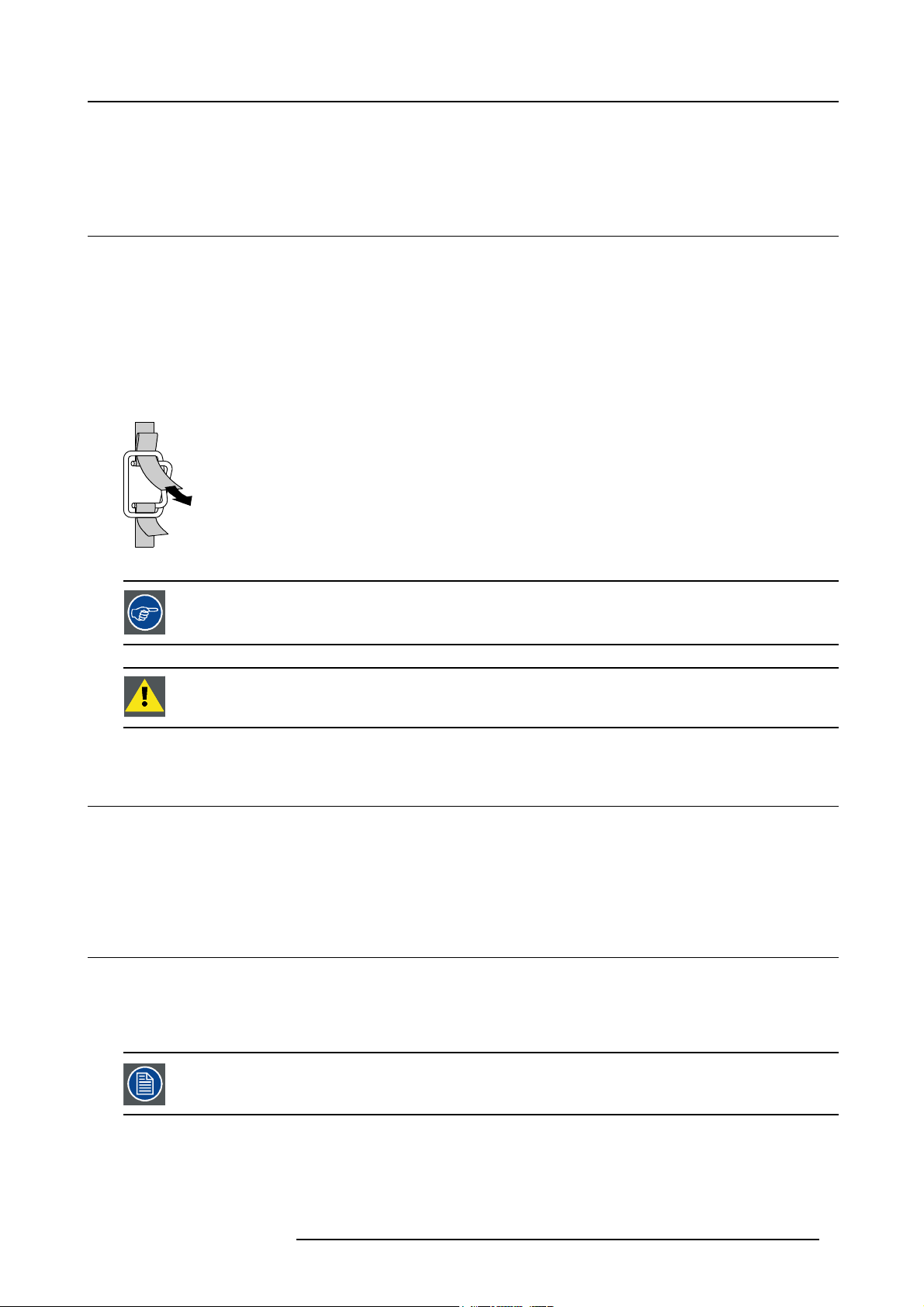
To unpack
1. Release the fastening clips.
2. Remove the banding. Handle as shown in the drawing. (image 1-1)
3. Take the projector out of its shipping carton and place it on a table.
PULL
TO OPE
Image 1-1
1. Packaging and Dimensions
or is surrounded with foam. The
Save the original shipping carton and packing material, they will be necessary if you ever have to ship your
projector. For maximum protection, repack your projector as it was originally packed at the factory.
CAUTION: Never transport the projector with the lens mounted on it !
Always remove the lens before transporting the projector.
1.2 Lens Packaging
Way of Packaging
Lenses are supplied as an individual item.
They are packed in a carton.
1.3 Lamp House Packaging
Way of Packaging
The lamp house is supplied as an individual item.
They are packed in a carton.
Never transport the projector with the lamp mounted inside the projector.
R59770014 XLM HD30 25/05/2009 5
Page 10
1. Packaging and Dimensions
1.4 Box content
Content
• 1 XLM HD30 projector (weight 180 kg) without lamp house and lens.
• 1 remote control unit (RCU) + 2 batteries
• 1 rugged remote control
• 1 owners manual
• 1 safety manual
• 1 female plug P3 + NE 400V (red)
• 1 female plug P3 + E 250V (blue)
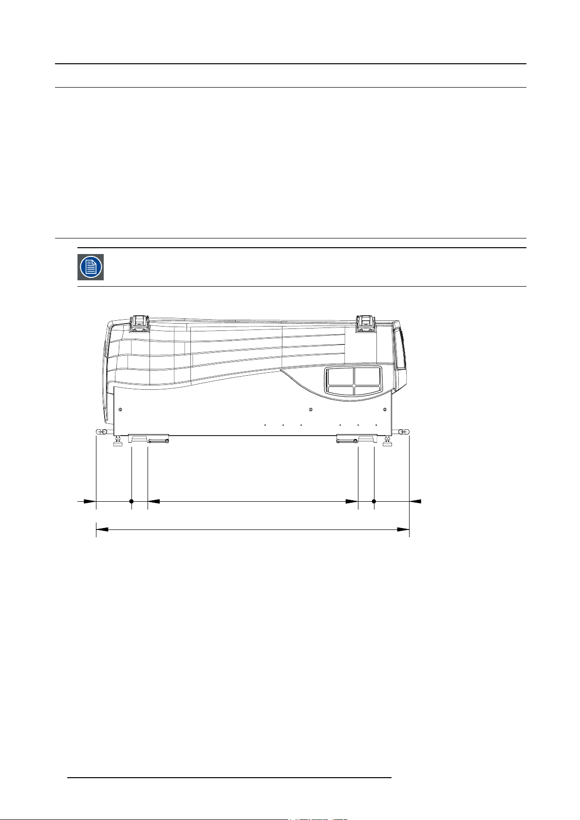
1.5 Dimensions
Dimensions are given without lens.
Side view
176
80
1050
80
176
1563
Image 1-2
Side view
6 R59770014 XLM HD30 25/05/2009
Page 11
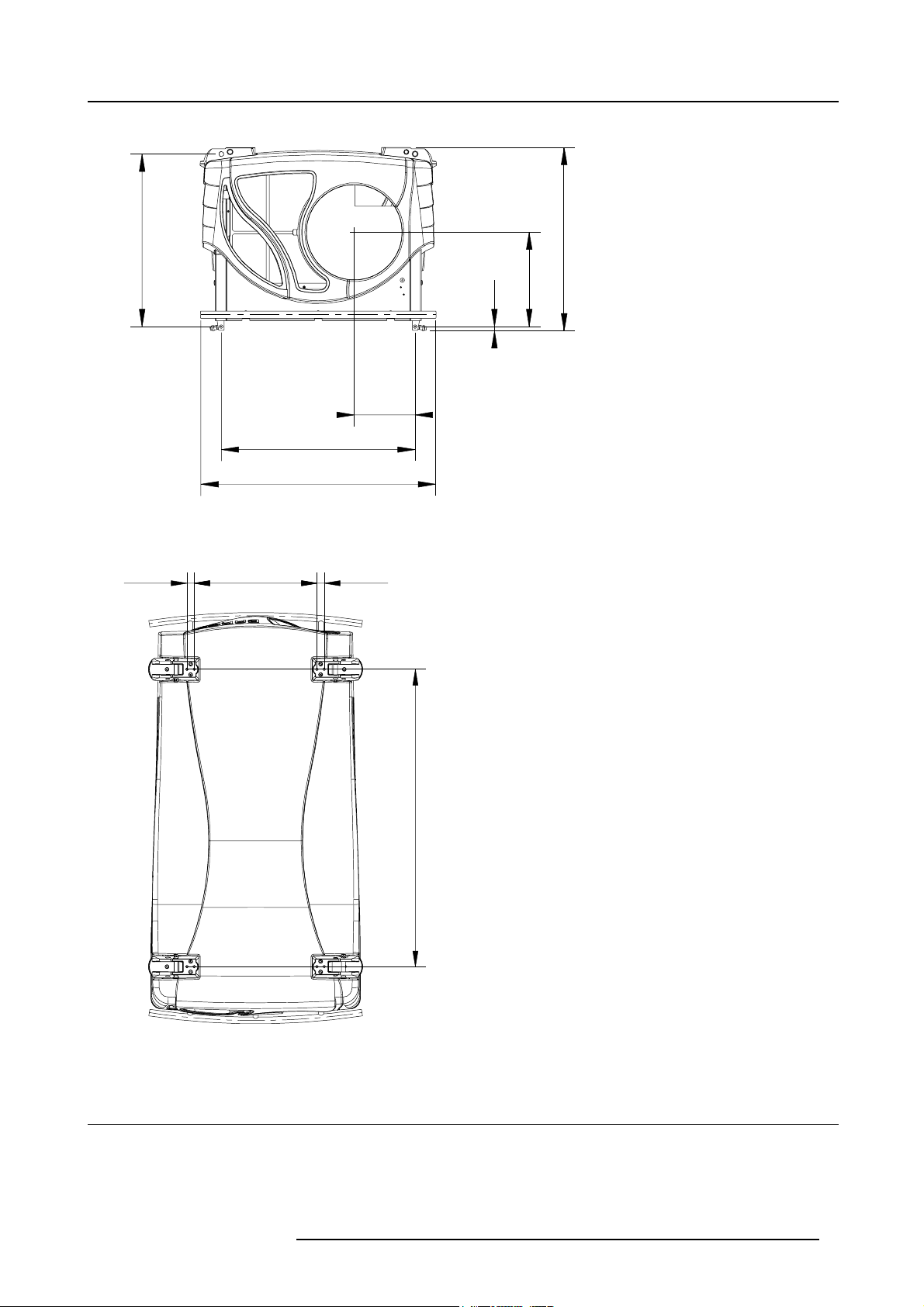
Front view
27,5
468
27,5
1. Packaging and Dimensions
598
Image 1-3
Front v iew
Top v i e w
669
810
210
15
636
327
1130
Image 1-4
To p vi ew
1.6 Free download of Projector Toolset
About Projector Toolset
Projector Toolset is a software tool to set up, configure, manage and control Barco projectors.
R59770014 XLM HD30 25/05/2009
7
Page 12

1. Packaging and Dimensions
The concept of this Projector Toolset software is modular. The basic package can be extended with several optional device plug-in
modules, now and in the future available.
The Projector Toolset software works with configurations that can be loaded. Within a configuration, different snapshots can be take.
A snapshot represents a current state of a configuration and can be reloaded to return to this typical state. These terms will be used
through the complete software.
Projector Toolset is a stand-alone application that runs on a Java Virtual Machine and that does not require extra services to run.
Several configurations can be controlled simultaneously. Even when the configurations are connected via different ways.
Projector Toolset is only available in a download version, no CD can be ordered.
Where to find the download file(s)
The program and all necessary plug-ins, as well as the Reference manual can be downloaded for free from Barco’s Partnerzone,
(URL: w
ww.partnerzone.events.barco.com). Registration is necessary.
If you are not yet registered, click on Partnerzone registration and follow the instructions. With the created login and password, it is
possible to enter the partnerzone where you can download the Projector Toolset software and the device plug-in updates as well as
the corresponding reference manual.
When downloading the complete Projector Toolset, this software contains already the latest devi
the latest core version of Projector Toolset, it is possible to download only device plug-in updates from the same web site location.
As Projector Toolset is a stand alone application, it is not necessary to install any other software. A Java virtual machine is included
with this download.
ce plug-ins. When you already have
Installation
Download first the reference manual (Part number: R5976925) and follow the installation instructions as written in this manual.
8
R59770014 XLM HD30 25/05/2009
Page 13
2. INSTALLATION GUIDELINES
Overview
• General guidelines
• Restricted Access Location
• Projector configuration
• Safety Area around projector
• Lenses
• Mounting the lamp house
• Transporting the projector
• Battery Insertion in the Remote Control
• Battery insertion in the Rugged remote control
• Charging the batteries of the rugged remote control
• Stacking Two Projectors
• Rigging points and clamps
2.1 General guidelines
WARNING: Before installing the projector, read first the safety instructions.
2. Installation Guidelines
Ambient Temperature Conditions.
Careful consideration of things such as image size, ambient light level, projector placement and type of screen to use are critical to
the optimum use of the projection system.
Max. ambient temperature : 35°C or 95 °F
Min. ambient temperature : 10 °C or 50 °F
The projector will not operate if ambient air temperature falls outside this range (10°C- 35°C or 50°F-95°F).
Storage temperature: -35°C to +65°C (-31°F to 149°F)
Humidity Conditions
Storage: 0 to 98 % RH Non-condensing
Operation: 0 to 95 % RH Non-condensing
Environment
Do not install the projection system in a site near heat sources such as radiators or air ducts, or in a place subject to direct sunlight,
excessive dust or humidity. Be aware that room heat rises to the ceiling; check that temperature near the installation site is not
excessive.
Environment condition check
A projector must always be mounted in a manner which ensures the free flow of clean air into the projectors ventilation inlets. For
installations in environments where the projector is subject to airborne contaminants such as that produced by smoke machines or
similar (these deposit a thin layer of greasy residue upon the projectors internal optics and imaging electronic surfaces, degrading
performance), then it is highly advisable and desirable to have this contamination removed prior to it reaching the projectors clean
air supply. Devices or structures to extract or shield contaminated air well away from the projector are a prerequisite, if this is not a
feasible solution then measures to relocate the projector to a clean air environment should be considered.
Only ever use the manufacturer’s recommended cleaning kit which has been specifically designed for cleaning optical parts, never
use industrial strength cleaners on the projector’s optics as these will degrade optical coatings and damage sensitive optoelectronics
components. Failure to take suitable precautions to protect the projector from the effects of persistent and prolonged air contaminants will culminate in extensive and irreversible ingrained optical damage. At this stage cleaning of the internal optical units will
be non-effective and impracticable. Damage of this nature is under no circumstances covered under the manufacturer’s warranty
and may deem the warranty null and void. In such a case the client shall be held solely responsible for all costs incurred during any
repair. It is the clients responsibility to ensure at all times that the projector is protected from the harmful effects of hostile airborne
particles in the environment of the projector. The manufacturer reserves the right to refuse repair if a projector has been subject to
wantful neglect, abandon or improper use.
R59770014 XLM HD30 25/05/2009
9
Page 14
2. Installation Guidelines
Special Care for Laser Beams
Special care should be used when DLP projectors are used in the same room as performant laser equipment. Direct or indirect hitting
of a laser beam on to the lens can severely damage the Digital MicroMirror Devices™ in which case there is a loss of warranty
Which screen type ?
There are two major categories of screens used for projection equipment. Those used for front projected images and those for rear
projection applications.
Screens are rated by how much light they reflect (or transmit in the case of rear projection systems) given a
of light projected toward them. The ‘GAIN’ of a screen is the term used. Front and rear screens are both rated in terms of gain.
The gain of screens range from a white matte screen with a gain of 1 (x1) to a brushed aluminized screen with a gain of 10 (x10)
or more. The choice between higher and lower gain screens is largely a matter of personal preference
called the Viewing angle. In considering the type of screen to choose, determine where the viewers will be located and go for the
highest gain screen possible. A high gain screen will provide a brighter picture but reduce the viewing angle. For more information
about screens, contact your local screen supplier.
determined amount
and another consideration
What image size? How big should the image be?
The projector is designed for projecting an image size : min 1.00m (3.3ft) to max 15 m (49.2ft) (depending on the ambient light
conditions), with an aspect ratio of 1.9:1.
2.2 Restricted Access Location
Installation in a Restricted Access Location
The XLM HD30 can only be installed in a Restricted Access Location.
What is a Restricted Access Location (Definition) ?
Definition of a Restricted Access Location:
A location for equipment where both of the following paragraphs apply:
• Access can only be gained by SERVICE PERSONS or by USERS who have been instructed about the reasons for the restriction
applied to the location and about the precautions that shall be taken.
• Access is through the use of the TOOL or lock and key, or other means of security, and is controlled by the authority responsible
for the location.
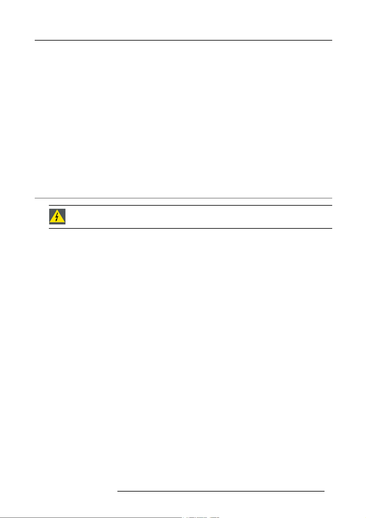
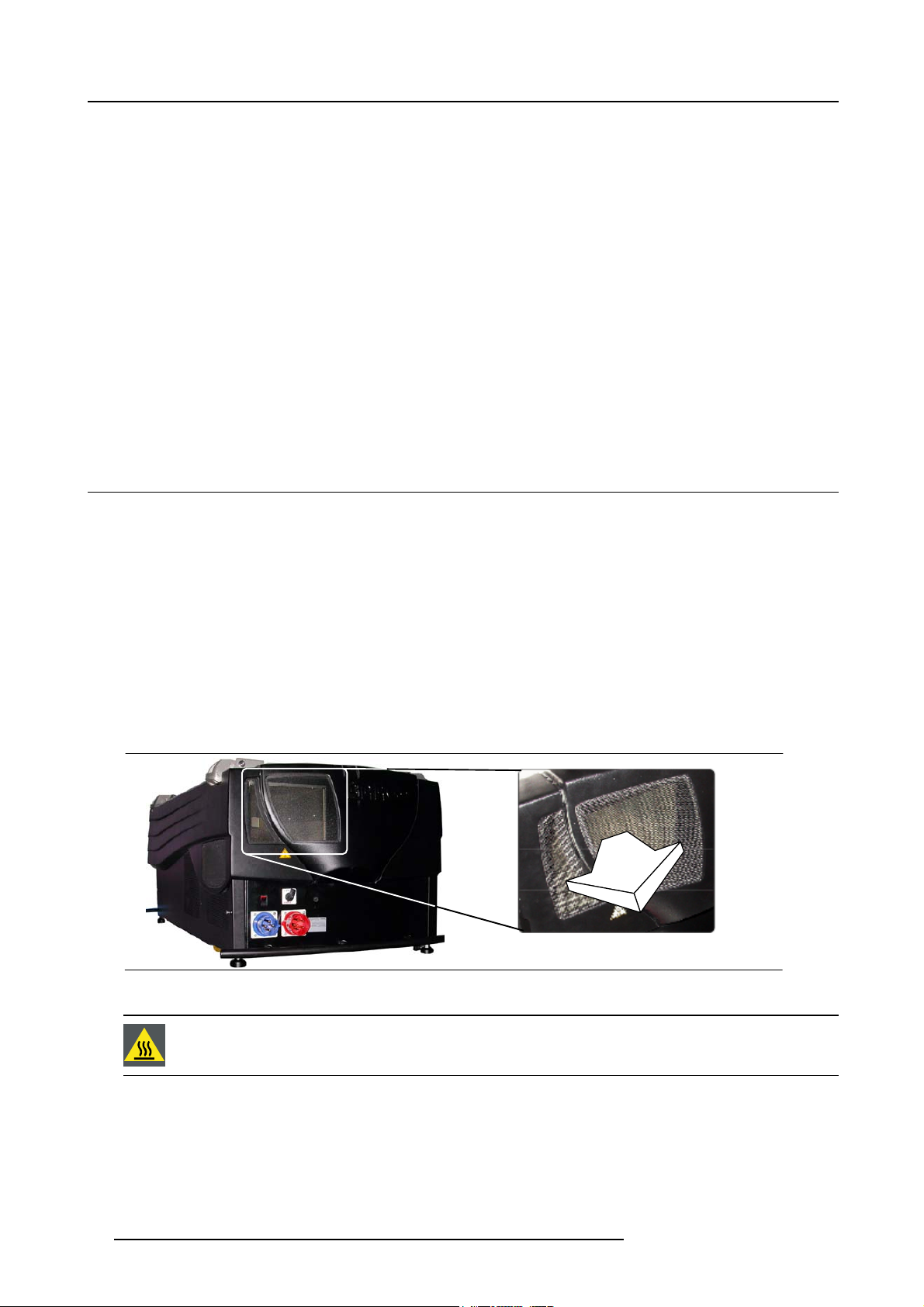
What is the Reason for the Applied Restriction?
The Air exhaust on the rear of the Projector can reach high temperatures due to the High Light Output Range of the installed lamp.
Image 2-1
The air exhaust on the rear side of the projector.
WARNING: Do not touch this Air Outlet Grill when the projector is running. Respect a cool down period for
at least 10 minutes after the projector has been switched off before touching this Grill .
10 R59770014 XLM HD30 25/05/2009
Page 15
2. Installation Guidelines
2.3 Projector configuration
Which configuration can be used ?
The projector can be installed to project images in four different configurations:
• Front/table
• Rear/table
• Front/ceiling
• Rear/ceiling
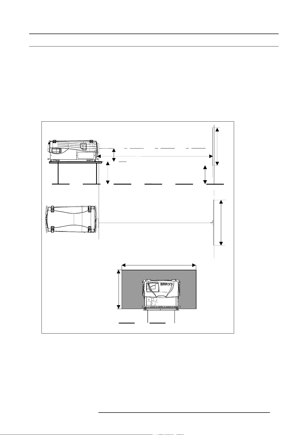
Positioning the projector
The projector should be installed perpendicular with the screen on a distance PD and water leveled in both directions. The mounting
positions in the following images are shown for a nominal lens position.
(1)
(4)
A
PD
SH
(2)
(3)
CD
CD = SH/2 + B - A
SH
B
(5)
SW
SW
Image 2-2
Front-table configuration
(1) Side view
(2) Top view
(3) Back view
(4) Optical axis projection lens
(5) Floor
CD distance between projector and fl oor
PD Projector distance, distance between screen and projector
SW Screen width (image width)
SH Screen height (image height)
R59770014 XLM HD30 25/05/2009
(5)
11
Page 16
2. Installation Guidelines
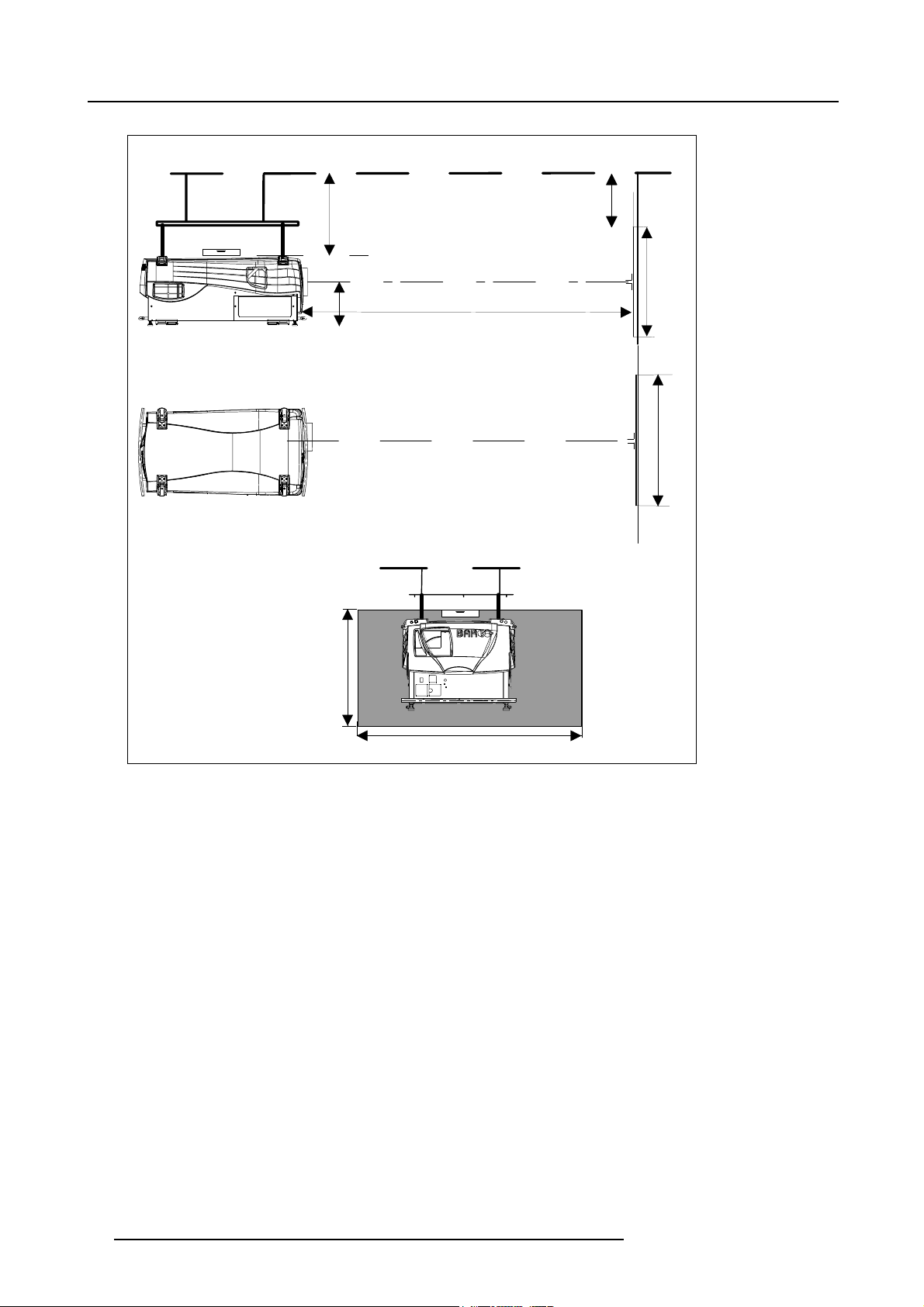
(4)
(4)
(1)
(2)
(3)
CD
B
SH
A
PD
SW
SH
Image 2-3
Front-ceiling configuration
(1) Side view
(2) Top view
(3) Back view
(4) Ceiling
CD distance between projector and ceiling
PD Projector distance, distan
SW Screen width (image width)
SH Screen height (image height)
ce between screen and projector
(3)
SW
12
R59770014 XLM HD30 25/05/2009
Page 17
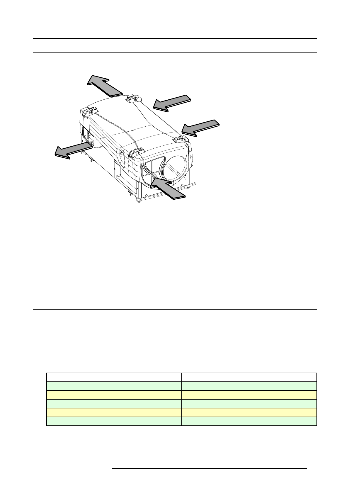
2.4 Safety Area around projector
A
Safety area
B
B
2. Installation Guidelines
A
A
Image 2-4
Air inlet - outlet
A Air inlet
B Air outlet
Due to the air flow, the following free area is recommended :
• Lens side :
- within Light beam : within 2 meter no combustible materials.
- air inlet : 0.5 meter free area
• Backside : within 1 meter no combustible materials.
• Left and right side : 0.5 meter
2.5 Lenses
Overview
• Lenses
• Lens formulas
• Lens installation
2.5.1 Lenses
Available lenses
Lenses
XLD (1.45-1.8:1)
XLD (1.8-2.4:1)
XLD (2.2-3.0:1)
XLD (2.8-5.5:1)
XLD (5.5-8.5:1)
Order number
R9852090
R9852092
R9852094
R9852100
R9852920
R59770014 XLM HD30 25/05/2009 13
Page 18
2. Installation Guidelines
2.5.2 Lens formulas
Formulas
Lenses
XLD (1.45-1.8:1) PD
XLD (1.8-2.4:1) PD
XLD (2.2-3.0:1) PD
XLD (2.8-5.5:1) PD
XLD (5.5-8.5:1) PD
Due to production tolerances the real distances can differ by 2% from these calculated values.
For critical situations (fixed installs that use the lens at one of its extreme zoom positions) this should be
taken into account.
Formulas
=1.45 x SW
min
=1.80 x SW
PD
max
=1.80 x SW
min
=2.40 x SW
PD
max
=2.22 x SW
min
=2.98 x SW
PD
max
=2.84 x SW
min
=5.50 x SW
PD
max
=5.50 x SW
min
PD
=8.50 x SW
max
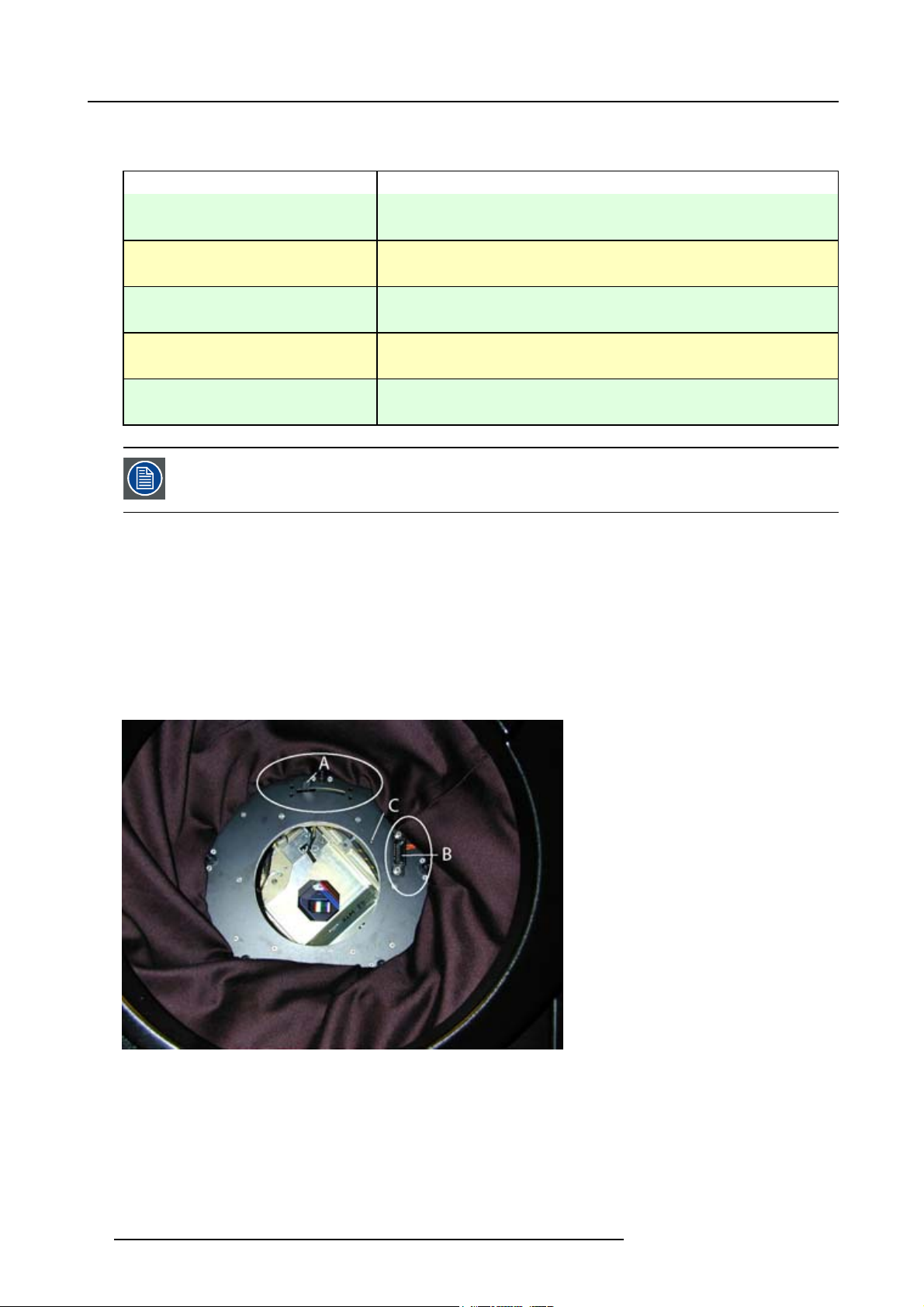
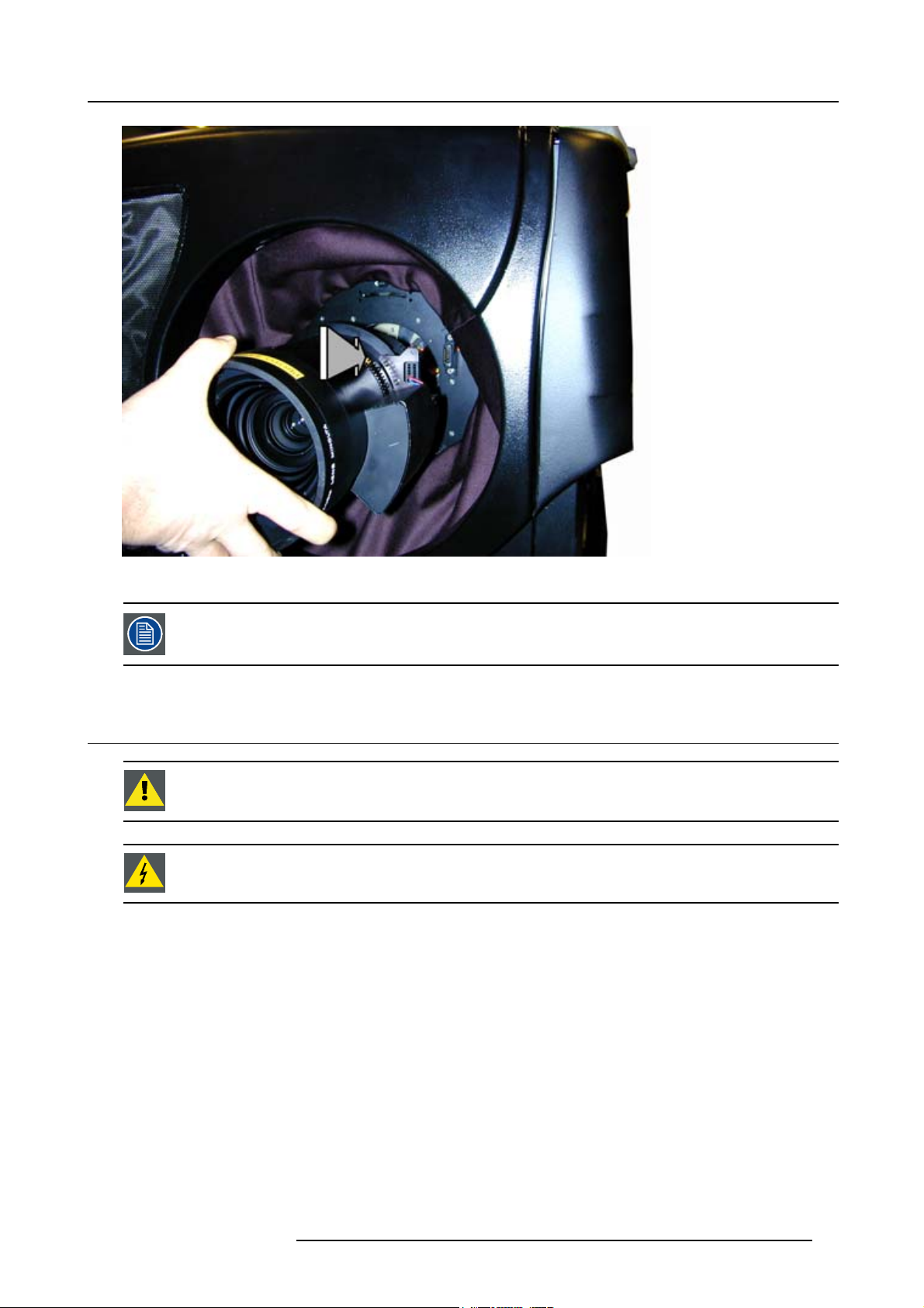
2.5.3 Lens installation
Howtoinstallalens?
1. Take out the foam rubber.
2. Put the lock handler to the left (A). (image 2-5)
3. Insert the lens in such a way that the connector matches the socket (B). (image 2-6)
4. Push on the lens until the connector seats into the socket. The notch (C) will match the hole in the lens.
5. Pull the handle (A) to the right to lock the lens position.
Image 2-5
Lens holder
A Lock handle
B Socket
CNotch
14
R59770014 XLM HD30 25/05/2009
Page 19
2. Installation Guidelines
Image 2-6
Mounting lens
For cleaning the lens, see "Cleaning the lens", page 128.
2.6 Mounting the lamp house
CAUTION: Never transport the projector with the lamp casing installed. The lamp casing should always been
transported in a vertical way to avoid damaging the lamp.
WARNING: Never attempt to disassemble the lamp from its housing or to dispose of it other than by returning
it to Barco. Due to its high internal pressure, the lamp may explode in either hot or cold state.
Necessary tools
• Nut driver 10mm
• Flat screwdriver 5mm
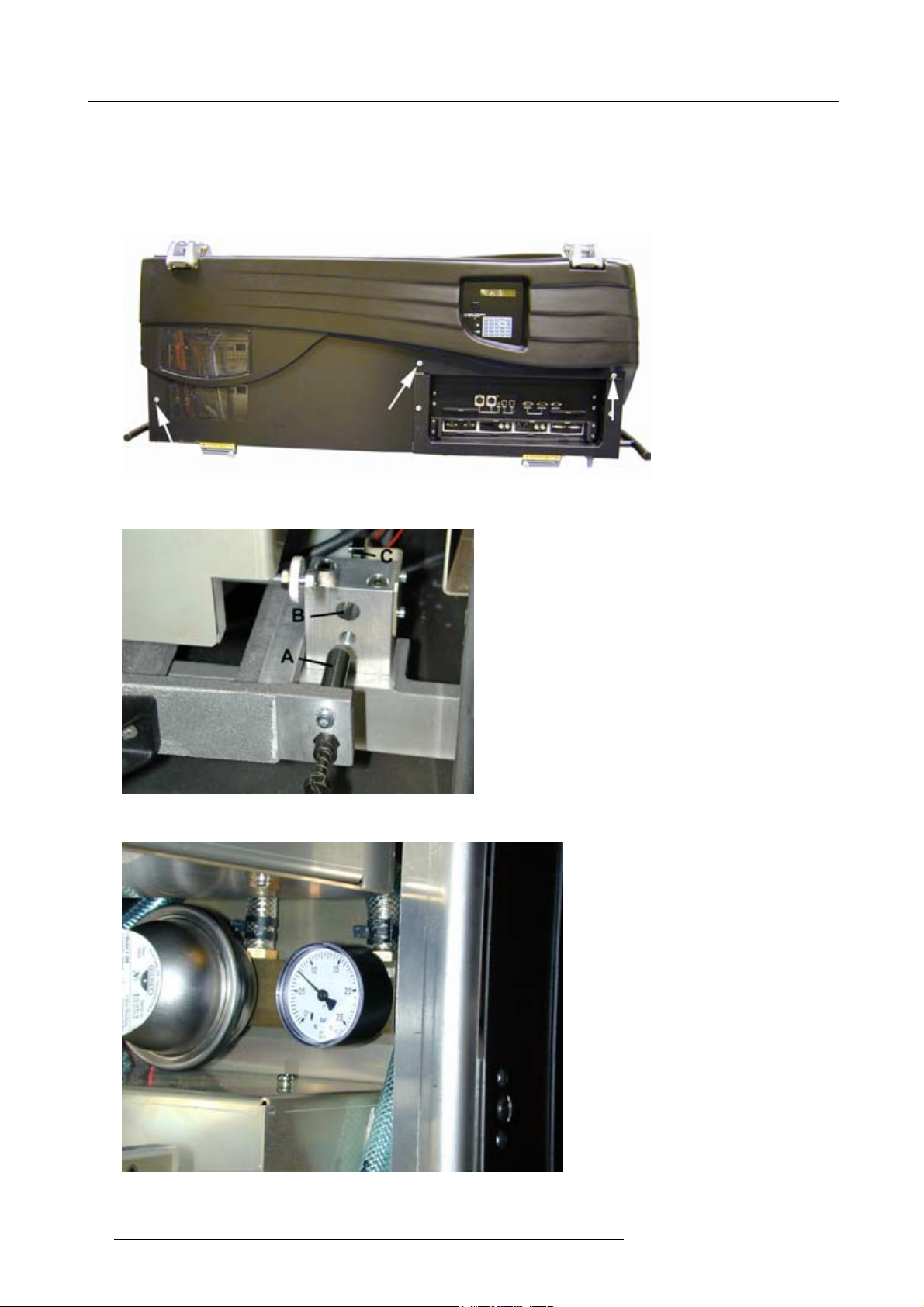
Installing the projection lamp
1. Unplug the projector from the wall outlet.
2. On the input side of the projector, remove the side by turning the 3 quarter turn fastener studs a quarter turn counter clockwise.
(image 2-7)
3. Pull the top side of the cover out of its spring locks.
4. Take the lamp casing by both handles carefully out of its shipping box.
5. Place the lamp casing on the optical base plate.
6. Push the lamp casing forward until the lamp slide fully into the projector. Both center pins (A) must match both center (B) holes.
(image 2-8)
If the center pins match the holes, the safety switch (C) will be activated (lamp ignition is possible).
R59770014 XLM HD30 25/05/2009
15
Page 20
2. Installation Guidelines
7. Secure the correct position by turning in both spring lock screws.
8. While the side cover is open, check the manometer. The manometer is situate on the top right of the lamp house compartment.
(image 2-9)
The pressure should be ± 1 bar. When lower than 0.5 bar, a corrective action should be taken by qualified service personnel.
9. Hook on the side cover and close the 3 quarter turn fastener studs a quarter turn clockwise.
Image 2-7
Removing side cover
Image 2-8
Lamp insertion
Image 2-9
Cooling liquid pressure
16 R59770014 XLM HD30 25/05/2009
Page 21
2. Installation Guidelines
CAUTION: While starting up the projector, the electronics detect if a lamp is installed. If no lamp is installed,
it is not possible to start up the projector.
Check the manometer on regular times, at least when replacing the lamp. The pressure should be ± 1 bar.
2.7 Transporting the projector
What to do?
1. Switch the projector to stand by.
2. Let cool down the projector for at least 15 minutes.
3. Switch off the projector and unplug from the wall outlet.
4. On the input side of the projector, remove the side by turning the 3 bolts a quarter turn counter clockwise (image 2-7).
5. Take off the side cover
6. Loosen the retaining bolts of the lamp (image 2-8).
7. Pull out the lamp casing. Wear heat resistant gloves, the case can be hot.
8. Pack the lamp casing into the original lamp packing and transport it vertically.
2.8 Battery Insertion in the Remote Control
Where to find the batteries
The batteries are not placed in the remote control to avoid remote control operation in its package, resulting in a shorter battery life
time.
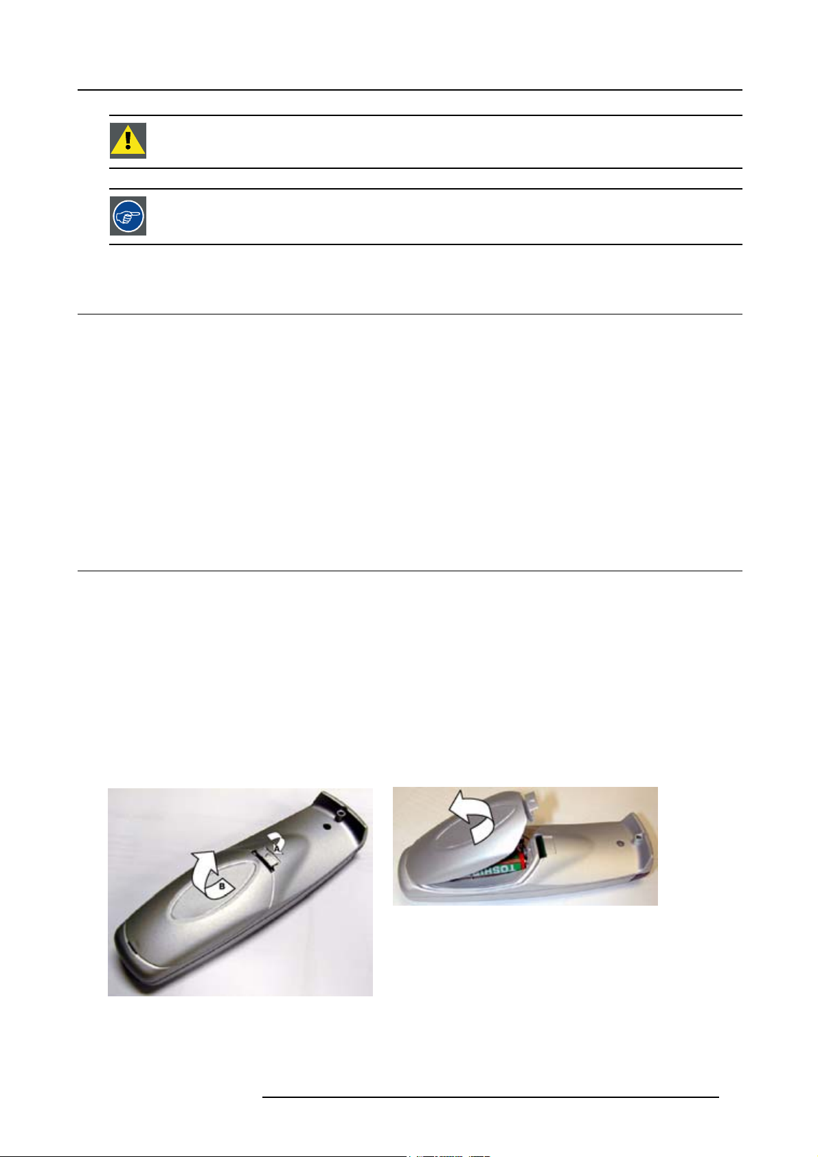
How to install the batteries
1. Push the cover tab (A) with the fingernail a little backwards and pull upwards the cover top (B). (image 2-10)
2. Slide the cover forwards to remove. (image 2-11)
3. Push the battery body towards the spring and lift it up to remov
4. Insert two AA size batteries, making sure the polarities match the + and – marks inside the battery compartment (image 2-12).
5. Insert the lower tab of the battery cover in the gap at the bottom of the remote control, and press the cover until it clicks in place
(image 2-11).
e. (image 2-12)
Image 2-11
Battery cover removal
Image 2-10
Battery cover unlock
R59770014 XLM HD30 25/05/2009 17
Page 22
2. Installation Guidelines
Image 2-12
Battery removal
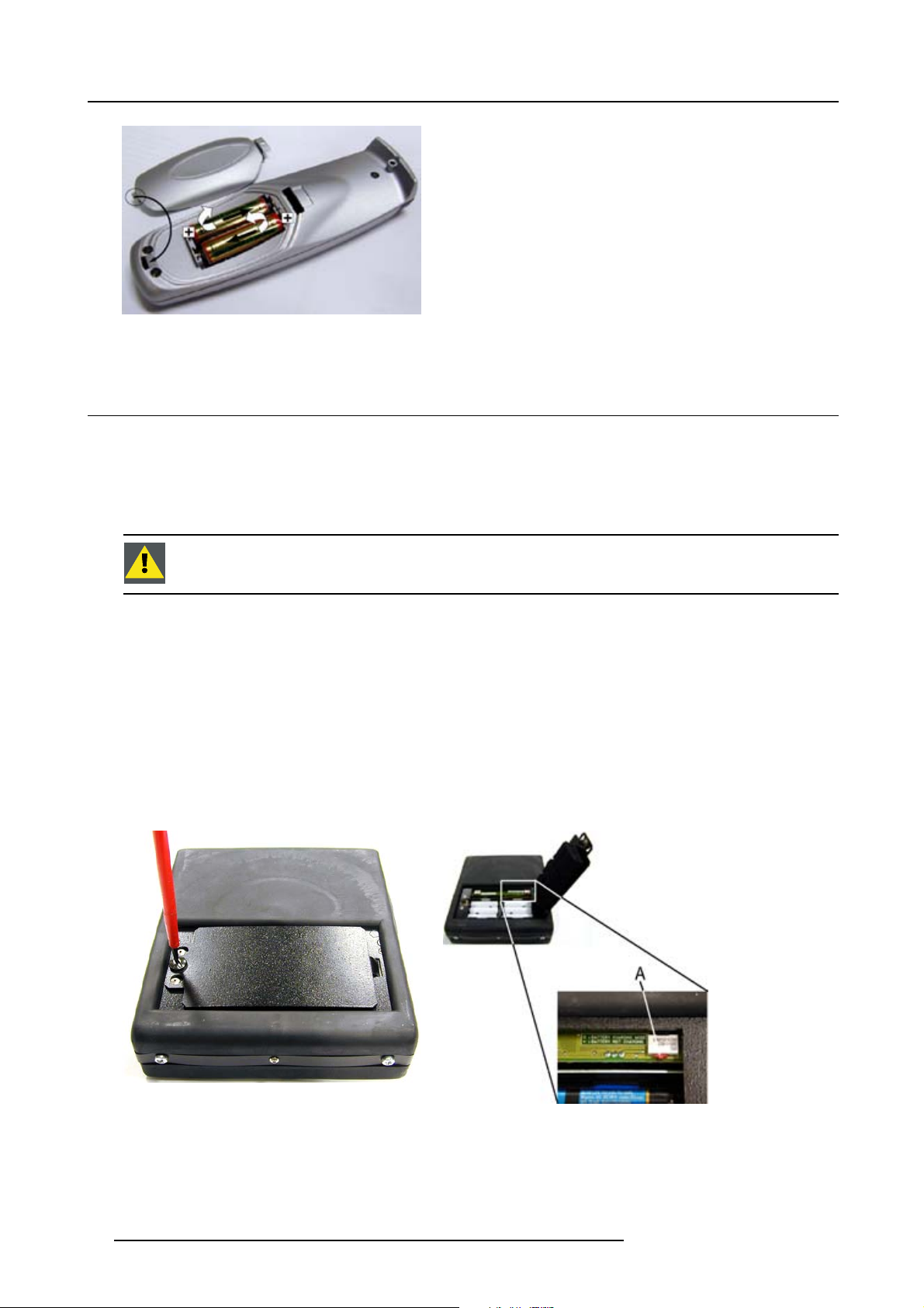
2.9 Battery insertion in the Rugged remote control
Batteries
The rugged remote control is delivered with 6 rechargeable NiCd batteries, type AA.
Expected charge and discharge cycles : 1000
When replacing the batteries, all batteries should be replaced at the same time.
CAUTION: Risk of explosion if the batteries are replaced by an incorrect type.
How to insert the batteries ?
1. Turn off the remote and remove all cables.
2. Turn the locking screw counter clockwise to free the metallic cover. (image 2-13)
3. Open the metallic cover.
4. Insert the new batteries correctly in the battery compartment. (image 2-14)
Be sure to install the batteries in the proper polarity and not to short battery terminals together.
5. Set switch A in the Charge position (left position).
6. Close the metallic cover.
7. Turn the locking screw clockwise to lock the metallic cover.
Image 2-13
Open the battery cover
18
Image 2-14
Charge switch
A Charge switch
R59770014 XLM HD30 25/05/2009
Page 23
2.10 Charging the batteries of the rugged remote control
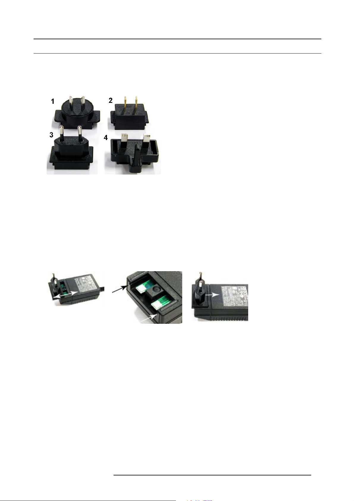
2.10.1 Preparing the charger
What can be done ?
The charger can be fitted with one of the four supplied power plugs.
Image 2-15
Possible power plugs
1ForAustralia
2 For US/Japan
3 Europe
4UK
2. Installation Guidelines
How to mount the correct plug ?
1. Pull the plug to be changed upwards until it is completely removed from the charger. (image 2-16)
2. Place the plug to be mounted on the charger and guide it downwards by using the guiding slots. (image 2-17)
3. Push the plug downwards until it clicks and is locked into the charger. (image 2-18)
4. Check if the plug is well locked.
It must not stick out of the charger.
Image 2-16
Remove plug
Image 2-17
Guiding grooves
Image 2-18
Mounting the plug
2.10.2 Charging the batteries
When charging the batteries
Charging is required whenever the batteries are low. The status of the batteries can be seen on the main menu (third line) or in the
diagnosis menu.
BAT=ACT The remote is working on batteries, there is no supply via external power source.
BAT=LOW The batteries are running low
Possible ways to charge the batteries
The batteries can be charged in one of the following ways :
• Via the battery charger
• Via the XLR connection with the projector when the projector is in standby or in operational mode.
Howtochargeviatheadapter?
1. Plug the female power connector of the charger into the male connector at the right side of the remote control.
2. Connect the charger to the wall outlet.
R59770014 XLM HD30 25/05/2009
19
Page 24
2. Installation Guidelines
2.10.3 Power save mode
Why used ?
When working on batteries, indicated on the main menu as BAT=ACT, the power save mode is enabled if there is no key hit within
2 minutes.
A message will be displayed : “POWER SAVE MODE”.
The remote control is automatically switched off after being approximately 10 minutes in the Power Save
Mode. Use the ON/OFF switch to reset the Remote control.
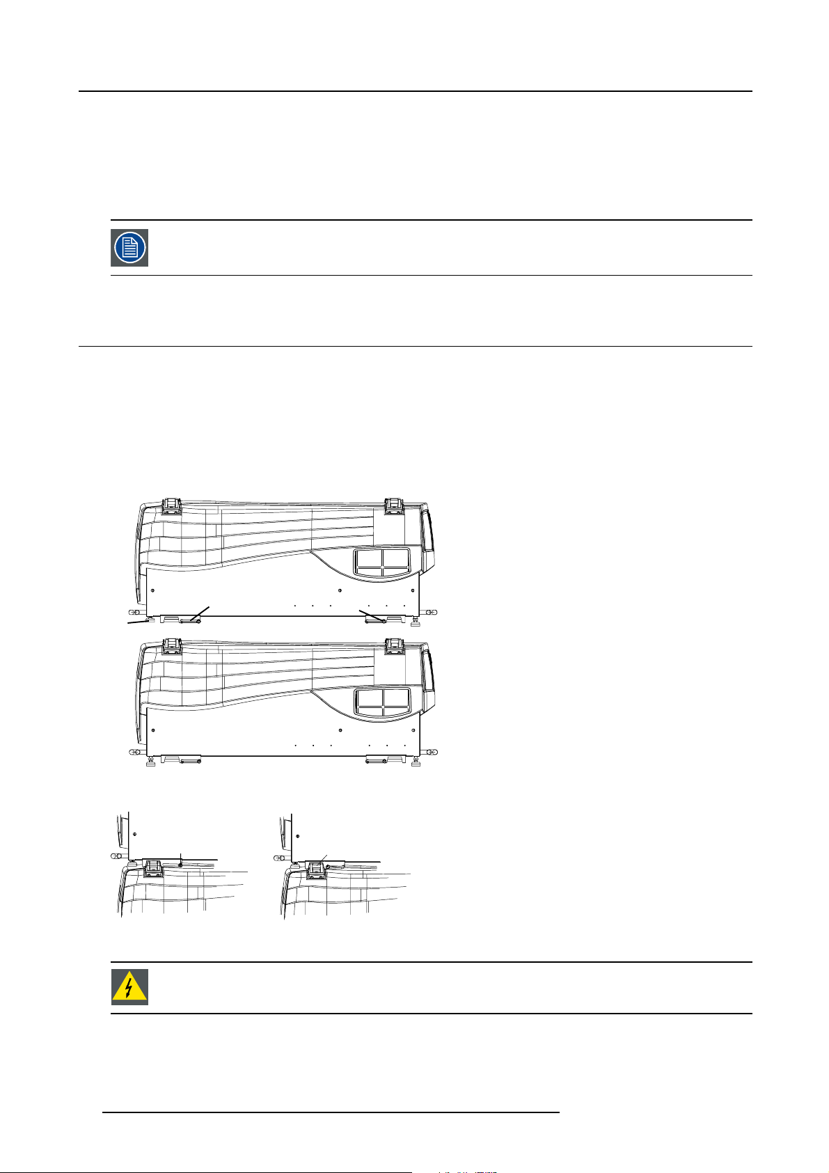
2.11 Stacking Two Projectors
How to handle
1. Turn in the four feet of the second projector.
2. Pull the handler A of the second projector a little backwards. (image 2-19)
3. Put the second projector on the first one so that the base plate of the second projector matches with the rigging socket of the fi rst
projector.
4. Slide the security pin (handler C) into the hole of the rigging socket of the first projector until the handler jumps into its socket (D).
(image 2-20)
Projector 2
B
Projector 1
Image 2-19
Stacking two projectors
C
Image 2-20
Stacking : security lock
A
A
D
WARNING: Close always the four security pins when stacking two projectors on each other.
20 R59770014 XLM HD30 25/05/2009
Page 25
2. Installation Guidelines
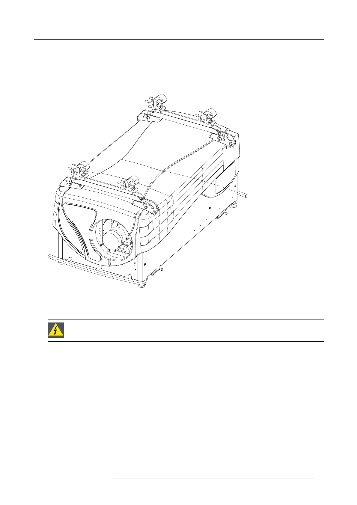
2.12 Rigging points and clamps
Clamps and brackets
Support bars, short and long, are available to be mounted on the projector so that the clamps can be fixed to these bars and the
projector can be mounted to a rigging system.
One example drawing is given below, for more possibilities, consult the complete documentation.
Image 2-21
Rigging kit mounted
Consult a professional structural engineer prior to suspending the ceiling mount from a structure not intended for that use. Always
ensure the working load limit of the structure supporting the projector.
WARNING: When mounting the projector to the ceiling or to a rigging system, always mount security chains.
Complete documentation
For a complete documentation consu
lt manual R5976765.
R59770014 XLM HD30 25/05/2009
21
Page 26

2. Installation Guidelines
22 R59770014 XLM HD30 25/05/2009
Page 27
3. CONNECTIONS
Overview
• Power connection
• Connection facilities
• Input source connection
• Communication connection
• Monitor output
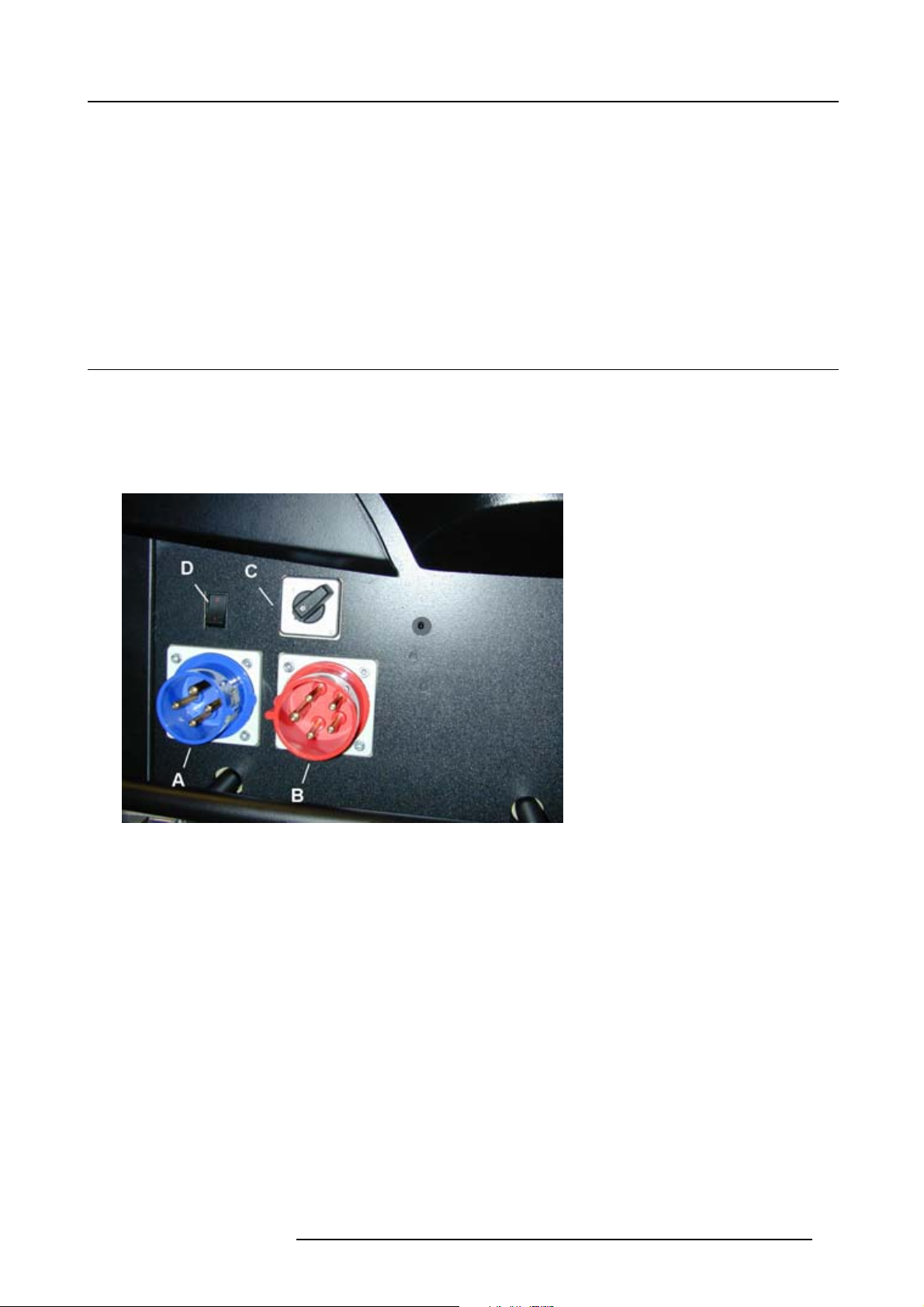
3.1 Power connection
Possibilities
The XLM HD30 can be powered on two ways:
• 3 power lines + neutral + earth line on 400V AC (red connector)
• 3 power lines + earth line on 250V AC (blue connector)
Field configurable via a selection switch.
3. Connections
Image 3-1
Possible power connections
A 3 power lines + earth on 250V AC
B 3 power lines + neutral + earth on 400V AC
C Power selection switch
D Power switch
Power consumption : 8 kW
R59770014 XLM HD30 25/05/2009
23
Page 28
3. Connections
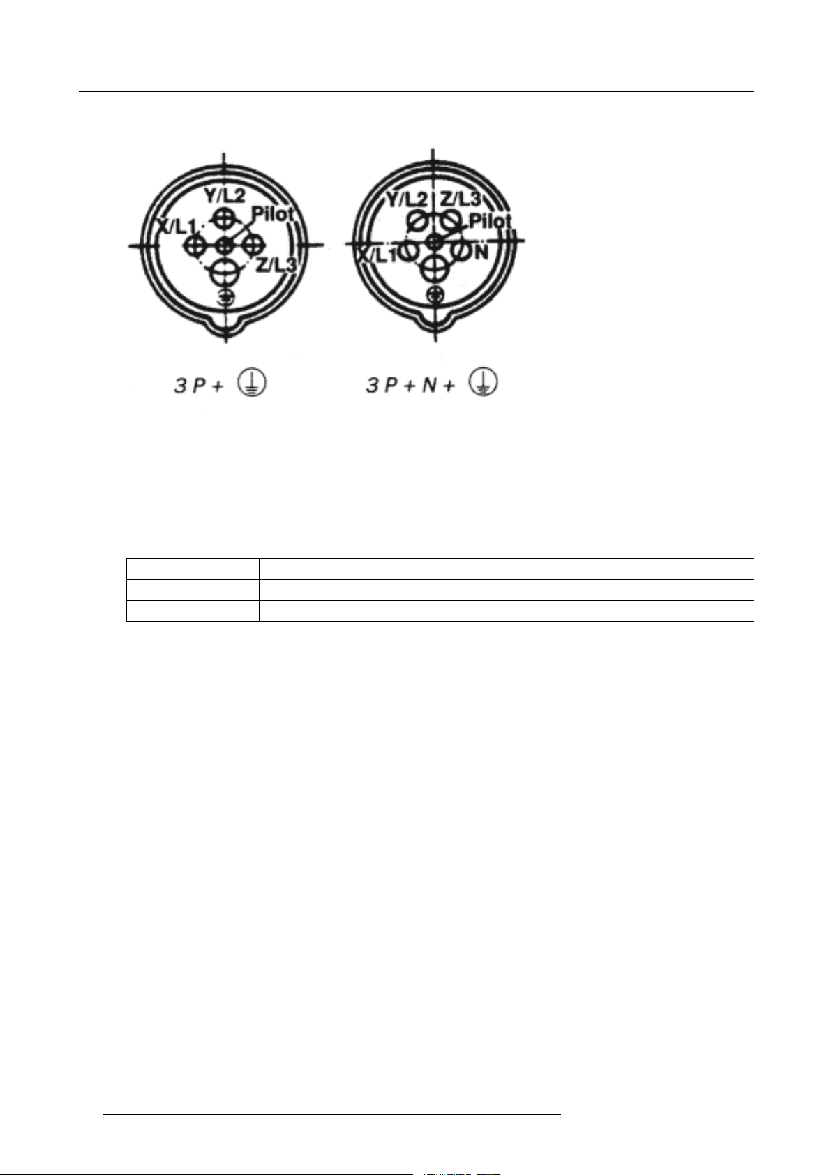
Pin connections of the power plug
Image 3-2
View from projector side.
How to connect ?
1. Plug the female connector of the power cord into the corresponding male connector on the projector.
Caution: Power Cord: the cross-sectional area of the conductor in the power s upply cord shall be not less than 4 mm
AWG 10.
2. Put the voltage selection switch in the correct position.
2
or
Switch position
Upper left
Lower left
3. Put the male connector of the power cable into the wall outlet
Description
3 x 208V
3 x 400V
.
24
R59770014 XLM HD30 25/05/2009
Page 29
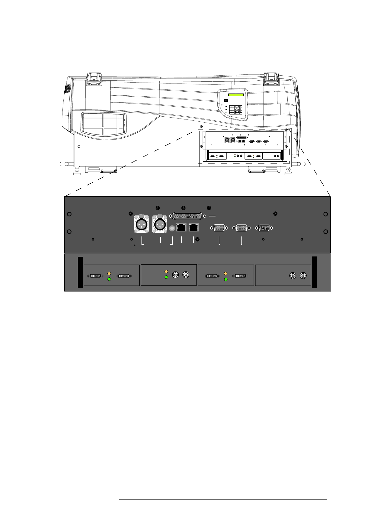
3.2 Connection facilities
Overview
GREEN : OPERATIONAL
RED : STAND-BY
3. Connections
EXIT
STANDBY
8097
ENTER
IR
56
TEXT
PAUSE
3
4
TINT
BRIGHTN
SHARPN
OK
21
COLOR
PHASE
CONTRAST
PUSH
PUSH
2
2 1
1
3
3
BI-DIRECTIONAL UNI-DIRECTIONAL
PUSH
L1
2
CTRL 3
3
L2
Image 3-3
Input facilities
• Layer 1 : communication input/outputs
• Hardwired remote
o
CTRL 1 : wired RCU
o
CTRL 2 : Uni-directional hardwired remote
o
CTRL 3 : Bi-directional hardwired remote
• Ethernet communication
o
Port 1 10/100 BaseT
o
Port 2 10/100 BaseT
- Wireless remote (optional)
- Serial network RS232/RS422 In/Out
- Monitor out
• Layer 2 : source inputs (standard)
-SDI
- HDSDI
-DVIuptoUXGA
- RGBHV analogue
Video and S-Video are optional inputs.
PUSH
1
2 1
3
CTRL 2 CT RL 1 PORT 1
HARDWIRED REMOTE 10/100 BASE T
PORT 2
WIRELESS REMOTE
RS232/422 IN
SERIAL NETWORK
RS232/422 OUT
MONITOR OUT
MONITOR OUT
R59770014 XLM HD30 25/05/2009
25
Page 30
3. Connections
3.3 Input source connection
Overview
• Introduction
• Removing and Inserting an input module
• DVI input module
• SDI input module
• HDSDI input module
• YUV / RG(s)B input module
• RGB analog input module
• CVBS / S-VID input module
• Dummy input module
3.3.1 Introduction
Overview
The source input layer (L2 on image 3-3) consists out of different input modules. Any combination is possible. Within the next topics
each input module will be discussed.
If no input module is inserted, the slot must be filled up by dummy input.
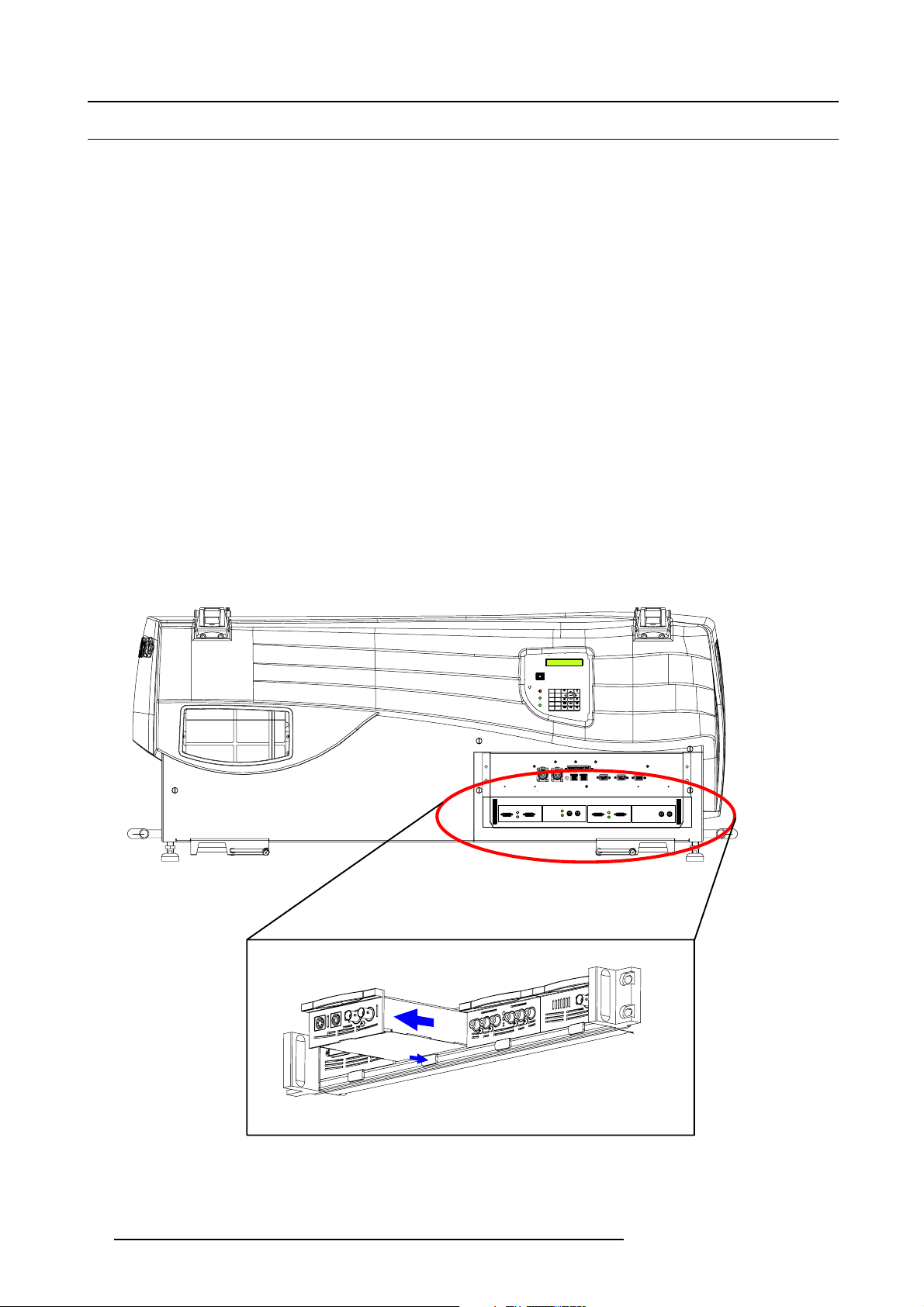
3.3.2 Removing and Inserting an input module
How to remove an input module?
1. Push on the release button underneath the input module (1) which you want to remove. At the same time pull out the input
module by the grip handle (2). (image 3-4)
GREEN : OPERATIONAL
RED : STAND-BY
EXIT
STANDBY
8097
ENTER
IR
56
TEXT
PAUSE
3
4
TINT
BRIGHTN
SHARPN
OK
21
COLOR
PHASE
CONTRAST
PUSH
PUSH
2
2 1
1
3
3
2
1
Image 3-4
Module insertion
26 R59770014 XLM HD30 25/05/2009
Page 31

3. Connections
How to insert an input module ?
1. Gently slide in the input module into a free input slot with the grip handle at the top.
2. Locking in the module by pushing the input module completely into the slot until a defi nite click is audible.
3.3.3 DVI input module
Technical info:
• Computer generated graphical source.
• DVI data in.
• 162 MHz pixel clock.
• Resolution from VGA to UXGA/60 Hz.
• DVI compliant.
• DVI loop through.
• Amber LED (upper LED on the front side) will be lit indicating module start up.
• When placed in an input slot the green LED (lower LED on the front side) will be lit indicating that the system acknowledges
the module.
IN OUT
Image 3-5
D320 DVI
Image 3-6
Order info:
Article No. Description
R9850960 D325Digitizer DVI input module
3.3.4 SDI input module
Technical info:
• SDI data in.
• SDI loop through.
• 270Mbit/s transmission (SMPTE 259M-C).
• 525/625 interlaced.
• Coax (75 Ohm).
• Amber LED (upper LED on the front side) will be lit indicating recognition of film, either continuous or intermittent film detection.
• When placed in an input slot the green LED (lower LED on the front side) will be lit indicating that the system acknowledges
the module.
IN OUT
Image 3-7
D320 SDI
Image 3-8
Order info:
Article No. Description
R9850970
R59770014 XLM HD30 25/05/2009 27
D325Digitizer SDI input module
Page 32

3. Connections
3.3.5 HDSDI input module
CAUTION: Maximum two HDSDI input modules may be inserted in one D325Digitizer.
Technical info:
• HDSDI data in (SMPTE292M).
• HDSDI loop through (SMPTE292M).
• Coax (75 Ohm).
• When placed in an input slot the green LED (lower LED on the front side) will be lit indicating that the system acknowledges
the module.
• Supported HDSDI standards:
- Progressive:
o
1280x720/60/1:1/ (SMPTE 296M)
o
1280x720/59.94/1:1/ (SMPTE 296M)
o
1920x1080/30/1:1/ (SMPTE 274M)
o
1920x1080/29.97/1:1/ (SMPTE 274M)
o
1920x1080/25/1:1/ (SMPTE 274M)
o
1920x1080/24/1:1/ (SMPTE 274M)
o
1920x1080/23.98/1:1/ (SMPTE 274M)
- Interlaced:
o
1920x1035/60/2:1/ (SMPTE 260M)
o
1920x1035/59.94/2:1/ (SMPTE 260M)
o
1920x1080/60/2:1/ (SMPTE 274M)
o
1920x1080/59.94/2:1/ (SMPTE 274M)
o
1920x1080/50/2:1/ (SMPTE 274M)
o
1920/1080/50/2:1 (1250)/ (SMPTE 295M)
o
1920x1080/24/Segmented/ (SMPTE 274M)
o
1920x1080//23.98/Segmented/ (SMPTE 274M)
IN OUT
Image 3-9
D320 HDSDI
Image 3-10
Order info:
Article No. Description
R9850980 D325Digitizer HDSDI input module
3.3.6 YUV / RG(s)B input module
Technical info:
• Component Video (BNC)
- R-Y : 0,7Vpp ±3dB 75 Ohm termination.
- Ys : 1Vpp ±3dB (0,7V Luma +0,3V Sync) 75 Ohm termination.
- B-Y : 0,7Vpp ±3dB 75 Ohm termination.
•RG(s)B(BNC)
- R : 0,7Vpp ±3dB 75 Ohm termination.
- G(s) : 1Vpp ±3dB (0,7Vpp G + 0,3Vpp Sync) 75 Ohm termination.
- B : 0,7Vpp ±3dB 75 Ohm termination.
• 3 BNC’s loop through connectors.
28
R59770014 XLM HD30 25/05/2009
Page 33

3. Connections
• Amber LED (upper LED on the front side) will be lit indicating recognition of film, either continuous or intermittent film detection.
• When placed in an input slot the green LED (lower LED on the front side) will be lit indicating that the system acknowledges
the module.
• Supports MacroVision™.
IN OUT
Image 3-11
D320 YUV/RGSB
Image 3-12
Order info:
Article No. Description
R9850940 D325Digitizer YUV / RG(s)B input module
3.3.7 RGB analog input module
Technical info:
• Sub D15 connector for input and loop through.
• R, G, B, Hsync, Vsync : 0 to 1 Vpp ±3dB 75 Ohm termination.
• Black level : 300mV.
•Sync-tip:0V
• Resolution : SXGA and UXGA version available.
• Amber LED (upper LED on the front side) will be lit indicating recognition of film, either continuous or intermittent film detection.
• When placed in an input slot the green LED (lower LED on the front side) will be lit indicating that the system acknowledges
the module.
IN OUT
Image 3-13
D320 RGB-AN
Image 3-14
Order info:
Article No. Description
R9850950
R9851710
R9853120
R59770014 XLM HD30 25/05/2009 29
D325Digitizer RGB analog SXGA input module
D325Digitizer RGB analog UXGA input module
D325Digitizer RGB analog input module
Page 34

3. Connections
3.3.8 CVBS / S-VID input module
Technical info:
• Video (BNC)
- CVBS : 1Vpp ±3dB (0,7V Video +0,3V Sync) 75 Ohm termination.
- BNC loop through connector.
• S-Video (4 pins DIN)
- Y : 1Vpp ±3dB (0,7V Video +0,3V Sync) 75 Ohm termination.
- U/V : 0,7Vpp ±3dB 100% color base, 75 Ohm termination.
- Chroma : Multi-Standard (PAL / SECAM / NTSC).
- 4 pins DIN loop through connector.
• Amber LED (upper LED on the front side) will be lit indicating recognition of film, either continuous or intermittent film detection.
• When placed in an input slot the green LED (lower LED on the front side) will be lit indicating that the system acknowledges
the module.
• Supports MacroVision™.
IN OUT
Image 3-15
IN OUT
D320 CVBS/S-VID
Image 3-16
Order info:
Article No. Description
R9850920 D325Digitizer CVBS / S-VID input module
3.3.9 Dummy input module
Technical info
• Dimensions : 103 x 181 x 41(W x D x H)
Image 3-17
D320 DUMMY
Image 3-18
Order info:
Article No. Description
R9850930 D325Digitizer dummy input module
30 R59770014 XLM HD30 25/05/2009
Page 35

3.4 Communication connection
Overview
• RS232/422 IN/OUT Serial network
• Ethernet connection
• Hardwired remote to CTRL 1
• Bi-directional communication port, CTRL 3
3.4.1 RS232/422 IN/OUT Serial network
RS232
An Electronic Industries Association (EIA) serial digital interface standard specifying the characteristics of the communication path between two devices using either D-SUB 9 pins or D-SUB 25 pins connectors. This standard is used for
relatively short-range communications and does not specify balanced control lines. RS-232 is a serial control standard
with a set number of conductors, data rate, word length and type of connector to be used. The standard specifies component connection standards with regard to computer interface. It is also called RS-232-C, which is the third version
of the RS-232 standard, and is functionally identical to the CCITT V.24 standard. Logical ’0’ is > + 3V, Logical ’1’ is < 3V. The range between -3V and +3V is the transition zone.
RS422
An EIA serial digital interface standard that specifies the electrical characteristics of balanced (differential) voltage,
digital interface circuits. This standard is usable over longer distances than RS-232. This signal governs the asynchronous transmission of computer data at speeds of up to 920,000 bits per se
standard for Macintosh computers. When the difference between the 2 lines is < - 0.2V that equals with a logical ’0’.
When the difference is > +0.2V that equals to a logical ’1’..
3. Connections
cond. It is also used as the serial port
Application
1. Remote control:
- easy adjustment of projector via a computer.
- allow storage of multiple projector configurations.
- wide range of control possibilities.
2. data communication
Pin configuration
BI-DIRECTIONAL UNI-DIRECTIONAL
PUSH
2 1
CTRL 3
Image 3-19
RS232/RS422 serial network connection
RS232/422 Serial Network IN
1
Data Carrier Detect (CD) 6 RXC+ Data Set Ready (DSR)
2 RXC- Receive Data (RD or RX or RXD)
3 TXC- Transmitted Data (TD or TX or TXD)
4TXC+ Data Terminal Ready (DTR)
5 GND Signal Ground (GND)
PUSH
2
3
1
3
CTRL 2 CTRL 1 PORT 1
HARDWIRED REM OTE 10/100 BASE T
PORT 2
WIRELESS REMOTE
RS232/422 IN
SERIAL NETWORK
MONITOR OUT
RS232/422 OUT
7
8
9
MONITOR OUT
Request to send (RTS)
Clear To Send (CTS)
Ring Indicator (RI)
-
RS232/422 Serial Network OUT
1
2RXB-
3TXB-
-
Receive Data (RD or RX or RXD)
Transmitted Data (TD or TX or TXD)
6RXB+
7
8
Data Set Ready (DSR)
-
-
R59770014 XLM HD30 25/05/2009 31
Page 36

3. Connections
RS232/422 Serial Network OUT
4TXB+
Data Terminal Ready (DTR)
5 GND Signal Ground (GND)
9
--
-
3.4.2 Ethernet connection
Connection
Connect port 1 or port 2 to a LAN by using a straight cable or a crossed cable. The connection is a 10/100 baseT.
Image 3-20
Ethernet connection
BI-DIRECTIONAL UNI-DIRECTIONAL
PUSH
PUSH
2 1
2 1
3
3
CTRL 3
CTRL 2 CTRL 1 POR T 1
HARDWIRED REMOTE 10/100 BASE T
PORT 2
WIRELESS REMOTE
RS232/422 IN
SERIAL NETWORK
RS232/422 OUT
MONITOR OUT
MONITOR OUT
The projector must have an IP address and the IP address of the connected PC must be within the same range of IP addresses.
Once getting access, it is possible to check and manipulate all projector settings. Remote diagnostics, control and monitoring become very simple.
The 2 ports are functionally identical. Both ports are connected via the projector hub.
Pin configuration
Ethernet 10/100 base T Port 1 & 2
1TXD+
2TXD- 6 RXD-
3RXD+
4 ++2.5VA 8 GNDM
5
++2.5VA
7
RXD-
3.4.3 Hardwired remote to CTRL 1
How to connect
1. Plug one end of the remote cable in the connector on the bottom of the RCU. (image 3-21)
2. Plug the other end in the connector in the input pan
Specifications of the CTRL 1 input:
-U
=9V
in
=80mA
-I
max
• Internal IR receiver can be disabled:
o
monojack: onpluginofthejack
o
stereo jack : on plug in or using an external switch bringing the right channel (B) to ground level. (image 3-22)
32
el of the projector labelled CTRL 1.
R59770014 XLM HD30 25/05/2009
Page 37

Image 3-21
Hardwired RCU
GREEN : OPERATIONAL
RED : STAND-BY
3. Connections
STANDBY
EXIT
8097
ENTER
IR
6
5
TEXT
PAUSE
3
4
TINT
BRIGHTN
SHARPN
OK
21
COLOR
PHASE
CONTRAST
PUSH
PUSH
2 1
2 1
3
3
D
AB C
2
3
1
1
2
Image 3-22
Stereo jack pin configuration
A tip : left channel
B ring : right channel
C screen : common (GND)
Dexternalswitch
1Stereojack
2 Mono jack
The Remote connection uses a standard two wire cable terminated on each end with a 3.5 mm male
(mono/stereo) phone jack.
This cable is not delivered but is available in most electronic or audio shops.
3.4.4 Bi-directional communication port, CTRL
3
What can be connected
The rugged remote control can be connected to the Bi-directional communication port CTRL 3.
With this rugged remote control all control functions can be taken over. The LCD panel on this rugged remote displays the same
information as the panel on the projector itself.
Pin assignment two way connector
12
3
Image 3-23
R59770014 XLM HD30 25/05/2009 33
Page 38

3. Connections
Pin Description
1
GND
2DATA+
3DATA-
How to connect via a cable ?
1. Plug one end of the twisted pare cable with XLR connector in the two way connector on the rugged remote (CTRL3). (image 3-24)
Fixed rate : 57600 baud
2. Plug the other end in the Bi-directional connector (CTRL 3) on the projector. (image 3-25)
Image 3-24
Rugged remote control, backside
GREEN : OPERATIONAL
RED : STAND-BY
0
9
STANDBY
EXIT
8
7
ENTER
IR
56
TEXT
PAUSE
43
BRIGHTN
TINT
SHARPN
OK
21
PHASE
COLOR
CONTRAST
PUSH
PUSH
2 1
2 1
3
3
Image 3-25
Bi-directional rugged remote control
How to set up the rugged remote control ?
1. Press ADJ key once.
The main menu of the rugged remote
2. Push the cursor key ↑ or ↓ to select Instal. Settings.
34
control will be started.
R59770014 XLM HD30 25/05/2009
Page 39

3. Press ENTER to select.
4. Push the cursor key ↑ or ↓ to select Communication.
5. Press ENTER to select.
6. Push the cursor key ↑ or ↓ to select Com m. Port.
7. Press ENTER to select.
8. Press ENTER to toggle between [Auto], [XLR], [RS232] and eventually [RF]
Select the corresponding setting. Two are possible in this setup.
Auto The rugged remote listens to according its priority. XLR has the highest priority.
XLR
The rugged remote is forced to XLR.
3.5 Monitor output
What can be done ?
A monitor can be connected to this output to preview the projected image.
Pin configuration
Monitor output
1
Red Out
2
Green Out
3
Blue Out
nc
4
5
Ground
6
Ground
7
Ground
8
9
10 ground
11
12
13
14
Ground
nc
nc
nc
Hor. Sync
Ver t. S ync
3. Connections
R59770014 XLM HD30 25/05/2009 35
Page 40

3. Connections
36 R59770014 XLM HD30 25/05/2009
Page 41

4. GETTING STARTED
Overview
• Terminology overview RCU and local keypad
• Terminology overview Rugged remote control
• Switching on the projector
• Lamp runtime
• Switching to standby
• Switching off
• Using the RCU
• Using the Rugged remote control
• Projector address
• Controlling the projector
• Quick lens adjustment
4.1 Terminology overview RCU and local keypad
Overview
The following table gives an overview of the different functions associated to the keys
4. Getting Started
.
1
F2
LOGO
F3
PIP
DIGI
ZOOM
PHASE
TINT
COLOR
BRIGHTN
CONTR
LENS
SHIFT
VOL
BACK
ENTER
19
2
0
9
7
5
3
1
STANDBY
8
6
4
SHARPN
2
TEXT
PHASE
ENTER
COLOR
TINT
EXIT
PAUSE
BRIGHT N
CONTRAST
3
4
5
6
7
8
9
10
F1
MENU
PAUSE
AUTO IMAGE
TEXT
90
SDI
7
DVI
5
VIDEO S-VIDEO
3
RGB
1
LENS
ZOOM
LENS
FOCUS
SB-PC
8
6
4
PC
2
21
20
18
17
16
15
14
13
12
11
Image 4-1
No. Key name Description
1 Function keys not used
R59770014 XLM HD30 25/05/2009 37
Page 42

4. Getting Started
No. Key name Description
2 MENU Menu key, to enter or exit the menus.
3 Address key
4
LOGO key
5
PAUSE to stop projection for a short time, press ’PAUSE’. The image disappears but full power is
6 STBY standby button, to start projector when the power switch is switched on and to switch off the
7
TEXT to deactivate or activate the on screen dialog boxes and menus.
8
AUTOIMAGE
9 Digit buttons direct input selection.
10 Lens control
11
VOL
12 Picture controls use these buttons to obtain the desired picture analog level.
13
DIGI ZOOM
14 FREEZE
15 PIP not used
16 ENTER
17
Cursor keys Cursor Keys on RCU or on the local keypad : to make menu selections or to access the
18
BACK to leave the selected menu or item (go upwards to previous menu).
19
EFFECTS
20
PIP ADJUST
21
RC operating indication lights up when a button on the remote control is pressed. (This is a visual indicator to
(recessed key), to enter the address of the projector (between 0 and 9). Press the recessed
address key with a pencil, followed by pressing one digit button between 0 and 9.
Lens adjustment key
retained for immediate restarting.
projector without switching off the power switch.
Attention : Switching to Standby. When the projector is running and you want to go
to standby, press the standby key for 2 seconds.
not used
use these buttons to obtain the desired ZOOM, SHIFT, FOCUS.
Not used
not used
press to freeze the projected image.
to confirm an adjustment or selection in the MENU.
menu bar.
not used
window select
check the operation of the remote control)
38 R59770014 XLM HD30 25/05/2009
Page 43

4.2 Terminology overview Rugged remote control
Overview
4. Getting Started
Image 4-2
Rugged remote control
No. Key name Description
1
STBY standby button, to start projector when the power switch is switched on and to switch off the
2 ADJ Adjust key, to enter or exit the menus. c
3EXIT
4 TEXT to des-activate or activate the on screen dialog boxes and menus.
5
ENTER
6
* key allows to recall the stored Logo (not in PiP mode)
7
Function keys
8 TEXTonLED redLEDtoindicatethetextstatus.
9
PAUSE LED yellow LED to indicate the pause status of the projector
10
Cursor keys Cursor Keys : to make menu selections or to access the menu bar.
11
PAUSE to stop projection for a short time, press ’PAUSE’. The image disappears but full power is
12 Address key to enter the address of the projector (between 0 and 9).
13 Digit buttons direct input selection.
projector without switching off the power switch.
Attention : Switching to Standby. When
to standby, press the standby key for 2 seconds.
Press ADJ once = entering the local menus of the rugged remote control.
Press ADJ twice = entering the menus of the projector.
to leave the selected menu or item (go upwards to previous menu). Corresponds with the
BACK button on the RCU.
to confirm an adjustment or selection in the MENU.
user programmable keys with functions for direct access.
retained for immediate restarting.
the projector is running and you want to go
orresponds with the Menu key on the remote control.
R59770014 XLM HD30 25/05/2009 39
Page 44

4. Getting Started
4.3 Switching on the projector
Howtoswitchon
1. Press the tumbler switch in the “1” position (“ON” state indicated by a visible red section of the switch).
- When “0” is visible, the projector is switched off.
- When “1” is visible, the projector is switched on.
The projector starts in standby mode. The projector indication LED is red.
Start image projection
1. Press Standby key once on the local keypad or on the remote control.
Note: It may take about 60 seconds before image projection, i.e. no projection until the completion of several operations (soft-
ware initialization, ...).
Note: The identification screen will be displayed during start up.
At startup, the active errors will be displayed on the screen and on the LCD display for a short period of time.
CAUTION: Pushing the standby key too long, might cause the projector to shut down right after an image is
displayed.
The lamp does not start up if a water cooling error is active.
When the lamp does not start up as it should be, the projector goes to standby. That makes a restart possible
by pressing on the standby button.
4.4 Lamp runtime
Lamp runtime indication while running
When the total runtime of the lamp is (1000 - 30) hours or more, a warning message will be displayed.
This warning message will be repeated at the next start up. Press BACK or MENU to remove the message.
The total lifetime of the lamp for a safe operation is 1000 hours maximum, do not use it longer. Always replace with the same type
of lamp. Call a Barco authorized service technician for lamp replacement.
Typical lamp lifetime = 500 hours, maximum lamp lifetime = 1000 hours.
WARNING: Using the lamp longer than its maximum lifetime is dangerous as the lamp could explode.
4.5 Switching to standby
How to switch to standby?
1. Press Standby to switch the projector to standby.
Switching to Standby. When the projector is running and you want to go to standby, press the standby key
for 2 seconds. Do not press any longer on the standby key otherwise the projector will restart.
40 R59770014 XLM HD30 25/05/2009
Page 45

When switching to standby, it takes 15 seconds before the projector can be switched on again.
4.6 Switching off
How to switch off the projector?
1. Press first Standby.
2. Let cool down the projector until the fans stop blowing, at least 15 min.
3. Switch off the projector with the power switch.
4.7 Using the RCU
Pointing to a reflective screen.
1. Point the front of the RCU to the reflective screen surface. (image 4-3)
4. Getting Started
Remote Control (A)
Image 4-3
Pointing RCU to the screen
F
A
1
D
J
9
7
5
3
0
1
4
A
TR
P
F
BA
2
EB
U
S
SS
E
LE
8
6
2
F
3
BA
B
TE
H
F
R
CO
S
H
4
V
G
CO
P
O
X
LA
T
I
T
A
N
R
A
L
LO
N
IN
C
T
H
S
T
N
R
T
P
E
R
E
N
EN
EX
T
TE
F
I
5
R
When using the remote control, make sure you are within the effective operating distance.
Theoperatingdistancemaybeupto15m(50ft).
The remote control unit will not function properly if strong light strikes the sensor window or if there are
obstacles between the remote control and the IR sensor.
IR sensor (C)
Screen (B)
R59770014 XLM HD30 25/05/2009 41
Page 46

4. Getting Started
Directly to one of the IR sensors
1. When using the wireless remote control, make sure you are within the effective operating distance (30m, 100ft in a straight line)
(image 4-4)
The remote control unit will not function properly if strong light strikes the sensor window or if there are obstacles between the
remote control unit and the projector IR sensor.
45° 45°
F
1
A
D
F
2
J
F
3
F
4
P
A
U
F
S
5
E
9
0
E
X
F
3
F
2
F
4
1
F
5
F
AD
J
E
X
I
T
T
R
E
E
N
P
A
U
S
E
T
X
E
T
AS
H
P
E
AR
9
0
S
H
P
N
7
8
N
T
I
T
5
6
O
C
L
O
R
3
4
B
R
I
G
H
T
N
1
2
C
O
N
T
R
T
E
R
B
L
E
A
B
L
A
N
C
E
B
A
S
S
V
O
L
Image 4-4
Remote control to IR sensors
1
T
R
E
B
L
E
B
A
S
S
V
O
L
I
T
7
5
T
E
E
X
N
T
8
T
E
R
A
3
S
4
P
H
6
A
R
E
S
H
P
N
T
I
N
2
T
C
O
L
O
B
R
R
I
G
H
T
C
N
O
N
T
R
B
A
L
A
N
C
E
F
3
F
2
F
4
F
5
F
1
AD
J
I
E
X
T
E
N
T
R
E
E
T
EX
T
P
A
U
S
P
H
A
S
E
9
0
A
H
R
S
P
N
8
7
T
T
N
I
6
5
C
O
L
O
R
4
3
R
I
B
H
G
TN
1
2
N
C
O
TR
T
E
B
L
E
R
B
A
L
A
N
CE
S
B
S
A
V
O
L
Hardwired remote control
The RCU can be connected via a cable with the projector. For more explanation, see "Hardwired remote to CTRL 1", page 32.
4.8 Using the Rugged remote control
Overview
The rugged remote control can be connected to the projector. For more explanation about the setup, see "Bi-directional communication port, CTRL 3", page 33.
Once set up, the rugged remote control can be used in the same way as the RCU. As this remote control has a limited number of
buttons, some functions are hidden in a the menu structure (e.g. picture controls)
4.9 Projector address
Overview
• Address setting
• Displaying and Programming addresses into the RCU
• Displaying and Programming addresses into the rugged remote control
4.9.1 Address setting
Projector address
Address installed in the projector to be individually controlled.
42 R59770014 XLM HD30 25/05/2009
Page 47

4. Getting Started
Common address
Default address. Projector will always execute the command coming from a RCU programmed with that common
address.
Why a projector address ?
As more than one projector can be installed in a room, the separate projector should be separately addressable with an RCU or
computer. Therefor each projector has its own address.
Set up an individual Projector Address.
The set up of a projector address can be done via the software.
Projector controlling.
Every projector requires an individual address between 0 and 255 which can be set in the Installation menu.
When the address is set, the projector can be controlled by :
• RCU for addresses between 0 and 9.
• computer, e.g. IBM PC (or compatible), Apple MAC, etc. for addresses between 0 and 255.
A projector will respond to a RCU set to the common address ’0’ regardless of what address is set in the projector itself (common
address of projector should also be “0” ).
The RCU is default programmed with address 0 , ’common address’.
If it is necessary to control a specific projector, then enter the projector address i
address is between 0 and 9). The projector with the corresponding address will listen to that specific RCU.
Some projectors may operate in domestic environments where other equipments may listen to the common
address “0” , therefore the common address can also be set to “1”.
4.9.2 Displaying and Programming addresses into the RCU
Displaying the Projector Address on the Screen.
1. Press the Address key (recessed key on the RCU) with a pencil.
The projector’s address will be displayed in a ’Text box’
To continue using the RCU with that specific address, it is necessary to enter the same address with the
digit buttons (address between 0 and 9) within 5 seconds after pushing the address key. For example : if the
Address key displays projector address 3, then press "3" digit button on the RCU to set the RCU’s address to
match the projector’s address. If the address is not entered within 5 seconds, the RCU returns to its default
address (zero address) and controls then all projectors in the room.
Address 0 (or 1) should always allow communication with the projector since it is a common address.
4.9.3 Displaying and Programming addresses into the rugged remote control
nto the RCU (only when that
Displaying the Projector Address on the Screen.
1. Press the Addr (address) key .
The projector’s address will be displayed in a ’Text box’
Programming the projector address into the rugged remote control
1. Press Addr key.
The remote jumps immediately to the address menu.
2. Enter the new address with the numeric keys (number between 1 and 255).
Or,
push the ↑ or ↓ key to fill out the desired address.
R59770014 XLM HD30 25/05/2009
43
Page 48

4. Getting Started
4.10 Controlling the projector
Input Selection
Key in the corresponding slot number with the digit keys on the remote control. The selected source will be displayed.
Priority setting is done in the Input slots menu.
PictureControlsviatheRCU
When an image control is pressed, a text box with a bar scale, icon and function name of the control, e.g. ’brightness...’ appears
on the screen (only if Textbox in the Display Setup menu is ON). The length of the bar scale and the value of the numeric indication
indicate the current memorized setting for this source. The bar scale changes as the arrows on the RCU a
buttons on the local keypad.
The picture settings are saved in the image file.
re pressed or the + or -
Brightness
Contrast Use the + button for a higher contrast.
Color Use the + button for richer colors.
Tint (Hue) Tint is only active for Video and S-Video when using the NTSC 4.43 or NTSC 3.58 system.
Phase Use the + or - button to adjust the phase.
Freeze
Use the + button for a higher brightness.
Use the - button for a lower brightness.
Use the - button for lower contrast.
Use the - button for lighter colors.
Use the + button
Use the - button.
Press Freeze to freeze the displayed image.
Picture Controls via the rugged remote control
The image controls are hidden in the RRC Internal menu. Press ADJ to enter the RRC Internal menu and select the desired control.
Press ENTER to select that control.
When an image control is selected, a text box with a bar scale, icon and function name of
on the screen (only if Textbox in the Display Setup menu is ON). The length of the bar scale and the value of the numeric indication
indicate the current memorized setting for this source. The bar scale changes as the arrows on the rugged remote control are
pressed (up arrow key acts as ’+’, down arrow key acts as ’-’).
The picture settings are saved in the image file.
the control, e.g. ’brightness...’ appears
The Pause Key
When the Pause key is pressed, the image projection is stopped, the mechanical shutter is closed.
To restart the image projection:
•PressPAUS E key
4.11 Quick lens adjustment
Overview
• Direct Lens Adjustment (RCU)
• Lens adjustment via menus
4.11.1 Direct Lens Adjustment (RCU)
Lens adjustment button on the Remote Control
On the Remote Control three buttons with double action are provided, allowing direct alignment for lens ZOOM, FOCUS and VERTICAL SHIFT.
1. Press LENS ZOOM button [-] or [+] (A) for correct image size on the screen.
2. Press LENS FOCUS button [-] or [+] (C) for an overall focus of the image.
3. Press LENS SHIFT button [-] or [+] (B) for correct vertical position of the image on the screen. (image 4-5)
44
R59770014 XLM HD30 25/05/2009
Page 49

4. Getting Started
B
A
C
Image 4-5
Lens adjustment with RCU
4.11.2 Lens adjustment via menus
How to adjust
1. Press the MENU button on the Remote control.
The main menu appears on the screen.
2. Select Installation and press ENTER.
3. Select Lens and press ENTER.
The lens menu will be displayed.
4. Select Zoom/Focus and press ENTER.
5. Use the ↑ and ↓ arrow keys to zoom, use the ← and → arrow keys to focus.
6. Press BACK to return to the lens menu.
7. Select Shift and press ENTER.
8. Use the ↑ and ↓ arrow keys for vertical shift, use the ← and → arrow keys for horizon
9. Press BACK to return to the lens menu.
10.Press MENU to exit the menu structure.
D
tal shift.
R59770014 XLM HD30 25/05/2009
45
Page 50

4. Getting Started
46 R59770014 XLM HD30 25/05/2009
Page 51

5. Getting used to the menu structure
5. GETTING USED TO THE MENU STRUCTURE
5.1 How to start up the menus
Box menu structure
The XLM HD30 has a box like menu structure which allows easy access to different parameters for setti
How to activate
1. Press MENU on the RCU.
The main menu will start up. (menu 5-1)
ng up the projector.
↑ or ↓ keys
ENTER
BACK (EXIT)
MENU (ADJ)
Key names between brackets correspond with the keys on the rugged remote control.
MAIN
Select a path from
below :
ADJUSTMENT MODE
INSTALLATION
SERVICE
Select with ↑ or ↓
then <ENTER>
<EXIT> to return
Menu 5-1
• these keys are used to scroll through the available items within a menu box.
• these keys are used to make adjustments.
•PressENTER to activate a selection
•UseENTER to confirm an adjustment.
•PressBACK to return to the previous menu. On rugged remote control, EXIT.
•PressMENU to start up the menu boxes
•PressMENU to exit the menu structure.
5.2 Using the Dialog boxes
How to use the dialog boxes ?
Some parameters are modified by means of a dialog box, where selections can be made and/or values can be entered.
The values can be entered/adjusted in several way:
Bar scale adjustment with the arrow keys
1. Use the ↑ or ↓ key or the ← or → to adjust the setting.
The bar scale will change. The value next to the bar scale will change accordingly.
Value adjustment using the numeric keys on the remote control
1. Press ENTER to activate the input field.
The first digit will be highlighted.
2. Enter the new value with the numeric keys on the remote control.
3. Select the next digit with the ← or → key and repeat step 2.
4. When finished, press ENTER.
Value adjustment using the arrow keys on the remote control
1. Press ENTER to activate the input field.
R59770014 XLM HD30 25/05/2009
47
Page 52

5. Getting used to the menu structure
The first digit will be highlighted.
2. Press ↑ or ↓ to increase or decrease the value.
3. Press ← or → to select the next digit to be changed.
4. Press ENTER to confirm the changes.
5.3 Menu memory
Overview
Each menu with sub menus, remembers its last selected sub item even when leaving the menu structure and that as long as the
projector is running. When restarting the projector from stand-by, the menu memory is reset.
After re-opening the main menu and selecting an item, the previous selected sub item of that selected item is highlighted and can
be opened just by pressing ENTER.
48
R59770014 XLM HD30 25/05/2009
Page 53

6. ADJUSTMENT MODE
Overview
• Adjustment mode overview
• Start up of the Adjustment mode
• File Service
• Picture Tuning
• Window Adjustment
• Layout Adjustment
• Scenergix
6.1 Adjustment mode overview
Overview
• File service
- Load
-Edit
- Rename
- Copy
- Delete
- Options
• Picture tuning
- Color space
- Color temperature
- Gamma
- Noise reduction
- Input balance
• Window adjustment
- Select source
-Size
-Position
- Z-order
- Color key
- Alpha blend
- No signal color
• Layout adjustment
- Load layout
- Rename layout
- Delete layout
- Add window
- Remove window
- Edit window
-Keystone
- Blanking
- Input locking
• ScenergiX
6. Adjustment Mode
6.2 Start up of the Adjustment mode
How to start up
1. Select Adjustment mode. (menu 6-1)
2. Press ENTER to select.
R59770014 XLM HD30 25/05/2009
49
Page 54

6. Adjustment Mode
The adjustment mode menu will be displayed. (menu 6-2)
MAIN
Select a path from
below :
ADJUSTMENT MODE
INSTALLATION
SERVICE
Select with ↑ or ↓
then <ENTER>
<EXIT> to return
Menu 6-1
6.3 File Service
Overview
• Possible file manipulations
•Startup
• Load file
•Editfile
• Rename
• Copy
• Delete
• File Options
Menu 6-2
ADJUSTMENT MODE
FILE SERVICE
PICTURE TUNING
WINDOW ADJUSTMENT
LAYOUT ADJUSTMENT
SCENERGIX
Select with ↑ or ↓
then <ENTER>
<EXIT> to return
6.3.1 Possible file manipulations
Connecting a new source.
Before using a new source, a correct file has to be installed. The projector’s memory contains a list of files corresponding to the most
used sources. When the new source corresponds with one of these files, the file can be loaded and saved for future use. When
there is a little difference, the file can also be loaded and then edited until t
he source specs are reached.
Possible file Manipulations
The following file manipulations are possible :
• Load : installation of a file for a new source.
• Edit : editing a loaded file to the source specs.
• Rename : renaming a file.
• Copy : copying a file.
• Delete : deleting a file
• Options : manual / automatic
File attributes
Each file can have a ’read’ or ’read-write’ attribute.
The following situation can be found on the menus:
•r—:file is read only.
•rw-:fi le has a read-write attribute and can be edited.
6.3.2 Start up
Start up
To enter the File Service , handle as follow :
1. Push the cursor key ↑ or ↓ to highlight F ile Service. (menu 6-3)
2. Press ENTER to select.
50
R59770014 XLM HD30 25/05/2009
Page 55

The File Service menu will be displayed. (menu 6-4)
6. Adjustment Mode
Menu 6-3
ADJUSTMENT MODE
FILE SERVICE
PICTURE TUNING
WINDOW ADJUSTMENT
LAYOUT ADJUSTMENT
SCENERGIX
Select with ↑ or ↓
then <ENTER>
<EXIT> to return
Menu 6-4
FILE SERVICE
Select with ↑ or ↓
then <ENTER>
<EXIT> to return
6.3.3 Load file
Start up Load file
To start up the load file, handle as follow :
1. Push the cursor key ↑ or ↓ to highlight Load. (menu 6-5)
2. Press ENTER to select.
The Load menu displays the corresponding files depending on the installed filter. (menu 6-6)
FILE SERVICE
LOAD
EDIT
RENAME
COPY
DELETE
OPTIONS
Select with ↑ or ↓
then <ENTER>
<EXIT> to return
LOAD FILE FILTER LIST [Fit]
Filename Re s Attr
vga-txt 720x400 r--
*vga-txt[1] 720x400 rw-
----------------------------Active : vga-txt[1]
↑,↓,0, 8 to scroll,
← to toggle filter
<ENTER> to load,
→ to preview
<EXIT> to return
LOAD
EDIT
RENAME
COPY
DELETE
OPTIONS
Menu 6-5
Menu 6-6
Changing the filter setting
1. Push the cursor key ↑ or ↓ highlight fi lter list.
2. Press ENTER to toggle the annotation between brackets.
[All] : all files that can be loaded will be displayed.
[Fit] : only the best fitting files will be displayed (with a distinction of ± 2 lines and line duration of ± 300 ns).
Howtoloadafile ?
1. Push the cursor key ↑ or ↓ to select the best fitting file. (menu 6-7)
2. Press ENTER to select.
3. Press ENTER to confirm the new creation or EXIT to return to the load file menu.
LOAD FILE FILTER LIST [Fit]
Filename Re s Attr
vga-txt 720x400 r--
*vga-txt[1] 720x400 rw-
----------------------------Active : vga-txt[1]
↑,↓,0, 8 to scroll,
← to toggle filter
<ENTER> to load,
→ to preview
<EXIT> to return
Menu 6-7
During a load file, the actual file is displayed next to the indication Active file and an ’*’ is set in the list.
R59770014 XLM HD30 25/05/2009 51
Page 56

6. Adjustment Mode
The image is not perfect ?
If the displayed image is not correct after selecting the best fitting file, go to the Edit menu, select the active file and change the File
settings.
6.3.4 Edit file
6.3.4.1 Start up
How to start up the Edit menu ?
1. Push the cursor key ↑ or ↓ to highlight Edit. (menu 6-8)
2. Press ENTER to select.
The Edit file adaptation menu will be displayed (automatic positioned on the actual fi le). (menu 6-9)
3. Select the filewhichmustbeedited(mostlytheactivefile).
4. Press ENTER.
The file name will be displayed in the upper right corner. (menu 6-10)
Menu 6-8
FILE SERVICE
LOAD
EDIT
RENAME
COPY
DELETE
OPTIONS
Select with ↑ or ↓
then <ENTER>
<EXIT> to return
*vga-txt[1] 720x400 rw-
-------------------------Active : vga-txt[1]
Menu 6-9
EDIT FILE
Filename Re s Attr
video525 675x180 rvideo625 675x556 r-
↑,↓,0, 8 to scroll,
<ENTER> to accept,
<EXIT> to return
EDIT FILE xga_60.s30
HORIZONTAL
TOTAL 1344 PIXELS
ACTIVE 1024 PIXELS
START 160 PIXELS
PERIOD 20678 nsec
VERTICAL (FIELD)
TOTAL 806 LINES
ACTIVE 768 LINES
START 9 LINES
OPTIONS
← , → <ENTER> to adjust
<EXIT> to return
Menu 6-10
6.3.4.2 Changing the settings
Different methods
The 3 different methods to change a setting will be described hereafter. These methods are:
• with the numeric keys on the remote control.
• with the arrow keys selecting the changing digit.
• with the arrow keys counting up or down.
How to change a setting with the numeric keys?
1. Push the cursor key ↑ or ↓ to highlight an item.
The color of the selected item will change.
2. Press ENTER to activate the digits.
3. Enter directly with the numeric keys on the RCU or local keypad the new value.
How to change a setting with the cursor keys?
1. Push the cursor key ↑ or ↓ to highlight an item.
The color of the selected item will change.
2. Press ENTER to activate the digits.
3. Push the cursor key ← or → to select the changing digit.
4. Push the cursor key ↑ or ↓ to scroll to the desired digit.
5. When finished, press ENTER to confirm.
How to change a setting with the cursor keys and counting up or down?
1. Push the cursor key ↑ or ↓ to highlight an item.
The color of the selected item will change.
2. Press ENTER to activate.
3. Counting up or down by pushing the cursor key ← or →.
52
R59770014 XLM HD30 25/05/2009
Page 57

6. Adjustment Mode
H
6.3.4.3 Correct value
What is already available during start up?
During the installation of a file with LOAD, the horizontal period, the total number of vertical lines are automatically measured and
filled out in the menu table. These values will be available when starting up the EDIT procedure of an active file.
CAUTION: Do not adjust these settings on an active file, they are used to identify the input source file.
How to find the correct values for the item in the Edit file menu?
Horizontal Total Pixels If the value for "Horizontal Total Pixels" is wrong, sampling mistakes (small vertical bars in the
Active Pixels The "Active Pixels" : determine the width of the window on the screen. This value is normally given in
Horizontal Start number of pixels between the start of the sync signal and the start of the video information.
Horizontal Period
Vertical Total Lines
Vertical Active Lines
Vertical Start number of lines between the start of the sync pulse and the start of the video signa
projected image) will be seen in the image.
Select "Total" and adjust the pixel quantity. Adjust for zero bars.
hint: if the number of bars increase, adjust in the other direction.
the source specifications. If not, adjust until full image is displayed (no missing pixels).
already filled in with the correct value when active file.
already filled when an active file is selected to be edited
number of horizontal lines determining the height of the projected image. This value is normally given
in the specification of the source. If not, adjust until full image height is dis
played (no missing lines)
l.
or. line
Frame
Hor. Start
Vert. Start
Active pixels
Hor. Pulse width
Hor. Total pixels
Active lines
Vert. Pulse width
Vert. Total lines
Image 6-1
Input settings
R59770014 XLM HD30 25/05/2009 53
Page 58

6. Adjustment Mode
How to install the correct settings for the options in the Edit file menu.
EDIT FILE OPTIONS
Source number 1
Clamp delay 8
Clamp width 20
Film Mode Detection [on]
Banner Protect [on]
Select with ↑ or ↓
←, →, <ENTER> to adjust
<EXIT> to return
Menu 6-11
Source number The source number of a non-active file can be changed to any other source number. This makes it
possible to create a file for future source numbers.
Clamp delay The time between the leading edge of the clamp pulse and the locked edge of the sync pulse. Can be
any value between 0 and 255. Use the ↑ or ↓ keys to change the value.
Clamp width The width of the clamp pulse can be any value between 0 and 255. Use the ↑ or ↓ keys to change
the value.
Film mode detection:
[On] or [Off]
Detects in the [on] mode if the source is film or video. Use the ENTER key to toggle between [on] or [off]
When enabled, the hardware looks for tell-tale signs of 3:2 or 2:2 pull-down sequences. These are the
result of converting cinema material recorded at 24 frames-per-second to the television frequencies
of 60 or 50 interlaced fields per second respectively. When FILM conversion is detected, the original
24 frames-per-second are restored. This avoids deinterlacing artefacts, and results in a perfect
artefact-free display. Note that in some cases (video clips, scrolling newstickers,...) FILM and VIDEO
material are mixed on one screen. This may confuse the detector and cause it to go into FILM
restoration mode. This will cause "jaggies" or motion artefacts. In such cases, disabling FILM mode
processing is the best cure.
Banner Protect: [On]
or [Off]
Only active when film mode detection is in the on position. Use the ENTER key to toggle between
[on] or [off].
FILM mode processing normally processes the entire display, but this may cause problems on sources
where video and FILM content are mixed. One very common example is scrolling banners at the
bottom of the screen (e.g. financial news). For those cases, the "banner protect" feature will force the
bottom quarter of the screen to be always processed in VIDEO mode, regardless of the rest of the
screen, which may be either video or FILM mode.
Leading edge
Trailingi ng edge
Sync
pulse
Clamp
pulse
Clamp
Clamp
delay
width
Image 6-2
Clamp delay and width
3:2 pull-down
Method used to map the 24 fps of film onto the 30 fps (60 fields) or 25 fps (50 fields), so that one film frame occupies
three video fields, the next two, etc. It means the two fields of every other video frame come from different film frames
making operations such as rotoscoping impossible, and requiring care in editing. Some sophisticated equipment can
unravel the 3:2 sequence to allow frame-by-frame treatment and subsequently re-compose 3:2. The 3:2 sequence
repeats every five video frames and four film frames, the latter identified as A-D. Only film frame A is fully on a video
frame and so exists at one time code only, making it the editable point of the video sequence.
54 R59770014 XLM HD30 25/05/2009
Page 59

2:2 pull-down
The process of transferring 24-frames/sec film format into video by repeating each frame (used for PAL DVD’s) as two
video fields. ( AD )
Artefacts
Undesirable elements or defects in a video picture. These may occur naturally in the video process and must be
eliminated in order to achieve a high-quality picture. Most common in analog are cross color and cross luminance.
Most common in digital are macroblocks, which resemble pixelation of the video image.
6.3.5 Rename
Start Up
To change the name of a selected fi le :
1. Push the cursor key ↑ or ↓ to highlight Renam e. (menu 6-12)
2. Press ENTER.
The Rename selection menu will be displayed. (menu 6-13)
3. Push the cursor key ↑ or ↓ to select a file name.
4. Press ENTER to select.
The Rename file menu will be displayed with the selected file name already filled in, in the ’From fi le name :’ area and in the ’To
file name :’ area. The first character in the ’To file name :’ area is highlighted. (menu 6-
6. Adjustment Mode
14)
Menu 6-12
FILE SERVICE
LOAD
EDIT
RENAME
COPY
DELETE
OPTIONS
Select with ↑ or ↓
then <ENTER>
<EXIT> to return
Menu 6-13
RENAME FILE
Filename Re s Attr
video525 675x180 rvideo625 675x556 rvga-txt 720x400 r-
------------------------------Active file : Video525
↑,↓,0, 8 to scroll,
<ENTER> to accept,
<EXIT> to return
From file name :
To file name :
Select with ← or →
Reprogram with ↑ or ↓
or numeric keys
<ENTER> to confirm
<EXIT> to return
Menu 6-14
RENAME FILE
xga1
xga2
Changing the characters
1. Push the cursor keys ← or → to select the desired character. (menu 6-15)
Or,
Change that character by pushing the cursor keys ↑ or ↓. Numeric characters can be entered directly with numeric keys on the
RCU.
Or,
Press ENTER to confirm.
The renamed file is entered in the list of files.
2. Press EXIT to return to the Rename menu selection.
No changes are made.
RENAME FILE
From file name :
xga1
To file name :
xga2
Select with ← or →
Reprogram with ↑ or ↓
or numeric keys
<ENTER> to confirm
<EXIT> to return
Menu 6-15
R59770014 XLM HD30 25/05/2009 55
Page 60

6. Adjustment Mode
6.3.6 Copy
Start Up
To copy the name of a selected file :
1. Push the cursor key ↑ or ↓ to highlight Copy.
2. Press ENTER.
The Copy selection menu will be displayed. (menu 6-16)
3. Push the cursor key ↑ or ↓ to select a file name.
4. Press ENTER to select.
The Copy file menu will be displayed with the selected file name already filled in, in the ’From file name :’ area and in the ’To file
name :’ area. The first character in the ’To file name :’ area is highlighted. (menu 6-17)
COPY FILE
Filename Re s Attr
vga-txt[1] 720x400 rwvideo525 675x180 rvideo625 675x556 r-
------------------------------Active file : Video525
↑,↓,0, 8 to scroll,
<ENTER> to accept,
<EXIT> to return
Menu 6-16
Menu 6-17
COPY FILE
Frome file name :
xga1
To file name :
xga2
Select with ← or →
Reprogram with ↑ or ↓
or numeric keys
<ENTER> to confirm
<EXIT> to return
Changing the characters
1. Push the cursor keys ← or → to select the desired character. (menu 6-18)
Or,
Change that character by pushing the cursor keys ↑ or ↓. Numeric characters can be entered directly with numeric keys on the
RCU.
Or,
Press ENTER to confirm.
The copy file is entered in the list of files.
2. Press EXIT to return to the Copy menu selection.
No changes are made.
COPY FILE
Frome file name :
xga1
To file name :
xga2
Select with ← or →
Reprogram with ↑ or ↓
or numeric keys
<ENTER> to confirm
<EXIT> to return
Menu 6-18
6.3.7 Delete
Start up and delete
To delete a selected file out of the list of files :
1. Push the cursor key ↑ or ↓ to highlight Delete. (menu 6-19)
2. Press ENTER.
The delete selection menu will be displayed. (menu 6-20)
3. Push the cursor key ↑ or ↓ to select a file name.
4. Press ENTER to select.
Aconfirmation menu "Delete file ’file name’?" is displayed. (menu 6-21)
56
R59770014 XLM HD30 25/05/2009
Page 61

5. Press ENTER to delete the file, press EXIT if you want to keep it.
Note: The ac tive fi le cannot be deleted.
6. Adjustment Mode
Menu 6-19
FILE SERVICE
LOAD
EDIT
RENAME
COPY
DELETE
OPTIONS
Select with ↑ or ↓
then <ENTER>
<EXIT> to return
DELETE FILE Filter list [ALL]
Filename Re s Attr
*vga-txt[1] 720x400 rw-
video525 675x180 rvideo625 675x556 r-
------------------------Active file : Video525
↑,↓,0, 8 to scroll,
<ENTER> to accept,
<EXIT> to return
Menu 6-20
6.3.8 File Options
Start up
1. Push the cursor key ↑ or ↓ to highlight Options. (menu 6-22)
2. Press ENTER to select.
The option selection menu will be displayed. (menu 6-23)
FILE SERVICE
LOAD
EDIT
RENAME
COPY
DELETE
OPTIONS
Select with ↑ or ↓
then <ENTER>
<EXIT> to return
FILE OPTIONS
FILE LOAD [AUTOMATIC]
Select with ↑ or ↓
then <ENTER>
<EXIT> to return
Menu 6-21
CONFIRM
DELETE FILE
Delete file :
Video525?
<ENTER> to confirm
<EXIT> to return
Menu 6-22
Menu 6-23
File Load
1. Press ENTER to toggle between [automatic] and [manual].
- [automatic] : correct file will be loaded automatically.
- [manual] : correct file has to be loaded manually.
6.4 Picture Tuning
Overview
•Startup
• Color Space
• Color Temperature
• Gamma
• Noise Reduction
• Input Balance
Color Space menu will only be available when the P7 functionality is activated. P7 functionality is a option for
the XLM projector and must be factory activated.
6.4.1 Start up
Start up
To improve the image quality, the items in the Picture Tuning menu can be toggled or adjusted. To start up the Picture Tuning :
1. Push the cursor key ↑ or ↓ to highlight Picture Tuning. (menu 6-24)
R59770014 XLM HD30 25/05/2009
57
Page 62

6. Adjustment Mode
2. Press ENTER to select.
The picture tuning menu will be displayed. (menu 6-25)
Menu 6-24
ADJUSTMENT MODE
FILE SERVICE
PICTURE TUNING
WINDOW ADJUSTMENT
LAYOUT ADJUSTMENT
SCENERGIX
Select with ↑ or ↓
then <ENTER>
<EXIT> to return
Menu 6-25
PICTURE TUNING
COLOR SPACE
COLOR TEMPERATURE
GAMMA
NOISE REDUCTION
INPUT BALANCE
Select with ↑ or ↓
then <ENTER>
<EXIT> to return
6.4.2 Color Space
Color space
A color space is a mathematical representation for a color. For example, the RGB color space is based on a Cartesian
coordinate system.
This function is only available when the P7 functionality is activated. P7 functionality is a option for the XLM
projector and must be factory activated.
What can be adjusted ?
The color space (gamut), the collection of colors which can be reproduced by the projector, can be adjusted to 3 predefined stored
values (one projector specific and 2 international standards). A custom adjustment is possible. The maximum color space which
can be displayed is the projector color space. This color space is measured at the factory and stored inside the projector.
6.4.2.1 Color Space selection
How to select ?
1. Push the cursor key ↑ or ↓ to highlight Color Space. (menu 6-26)
2. Press ENTER to select.
The Color Space selection menu will be displayed. (menu 6-27)
The actual selected color space is indicated next to Active and an ’*’ is placed before the item in the list.
3. Push the cursor key ↑ or ↓ to highlight the desired color space.
4. Press ENTER to select.
The selected color space will be applied. When Custom is selected, the actual custom values will be applied.
Menu 6-26
PICTURE TUNING
COLOR SPACE
COLOR TEMPERATURE
GAMMA
NOISE REDUCTION
INPUT BALANCE
Select with ↑ or ↓
then <ENTER>
<EXIT> to return
Menu 6-27
COLOR SPACE
C
olor space name Attr
Custom rw-
*EBU r--
Projector r--
SMPTE r-___________________________
Active: EBU
Select with ↑ or ↓
<ENTER> to adjust,
→ to edit/view
<EXIT> to return
6.4.2.2 Custom color space
How to setup ?
1. Push the cursor key ↑ or ↓ to highlight Color Space. (menu 6-28)
58
R59770014 XLM HD30 25/05/2009
Page 63

6. Adjustment Mode
2. Press ENTER to select.
The Color Space selection menu will be displayed. (menu 6-29)
The actual selected color space is indicated next to Active and an ’*’ is placed before the item in the list.
3. Push the cursor key ↑ or ↓ to highlight Custom.
The Edit color space menu opens. (menu 6-30)
4. Push the cursor key ↑ or ↓ to highlight one of the primary or secondary colors which must be changed and press ENTER.
5. Use the cursor keys to change the value or enter a new value with the digit keys.
PICTURE TUNING
C
olor space name Attr
Custom rw-
*EBU r--
Projector r--
SMPTE r-___________________________
Active: EBU
Select with ↑ or ↓
<ENTER> to adjust,
Menu 6-29
Menu 6-28
COLOR SPACE
COLOR TEMPERATURE
GAMMA
NOISE REDUCTION
INPUT BALANCE
Select with ↑ or ↓
then <ENTER>
<EXIT> to return
Note that it is common practice to set the targets outside the projector color space. This implies there would
be clipping if a fully saturated input was applied. In normal scenes, this does not happen, and the extra gain
or saturation helps balance the overall lock. If clipping occurs, there will typically be a hue shift when one of
R, G, B goes into clip ahead of the others.
6.4.3 Color Temperature
It is possible that when P7 is activated and the color temperature has been changed, the screen is all black
(no picture, no OSD). This can happen, due to the fact that for every change in color space setting the color
temperature also has to be set (that has to be done on the LCD as the OSD has disappeared).
6.4.3.1 Color Temperature selection
COLOR SPACE
→ to edit/view
<EXIT> to return
EDIT COLOR SPACE
Primaries: RED X 0.6400
Secondaries MAGENTA X 0.0000
↑, ↓, ←, →, <ENTER>, <EXIT>
Menu 6-30
RED Y 0.3300
GREEN X 0.2900
GREEN Y 0.6000
BLUE X 0.1500
BLUE Y 0.0600
MAGENTA Y 0.0000
CYAN X 0.0000
CYAN Y 0.0000
YELLOW X 0.0000
YELLOW Y 0.0000
What can be done ?
The color temperature can be selected according to the type of source.
There are 3 different preset color temperatures, 3200 K, 6500 K and 9300 K. These calibrated presets can be selected and will
provide optimum color tracking. The projector however allows t
he setting of a personal color temperature in custom or to choose for
Projector white.
Projector white
Native white of the projector (non calibrated white).
How to select ?
1. Push the cursor key ↑ or ↓ to highlight Color Temperature. (menu 6-31)
2. Press ENTER to select.
The Color Temperature selection menu will be displayed. (menu 6-32)
The actual selected color temperature is indicated next to Active and an ’*’ is placed before the item in the list.
3. Push the cursor key ↑ or ↓ to highlight the desired value.
4. Press ENTER to select.
R59770014 XLM HD30 25/05/2009
59
Page 64

6. Adjustment Mode
The selected color temperature will be applied. When entered on Custom, the actual custom values will be applied.
Menu 6-31
PICTURE TUNING
COLOR SPACE
COLOR TEMPERATURE
GAMMA
NOISE REDUCTION
INPUT BALANCE
Select with ↑ or ↓
then <ENTER>
<EXIT> to return
COLOR TEMPERATURE
C
olor tempe ra. name Attr
3200 r-
6500 r-
9300 r*Custom rw-
Projector White r_________________
ACTIVE: 6500
Select with ↑ or ↓
<ENTER> to accept,
→ to edit/view
<EXIT> to return
Menu 6-32
6.4.3.2 Custom color temperature
About custom color temperature
The custom values depend on the activation of the P7 functionality.
When no P7 functionality is activated, the custom color temperature is adjusted by the RGB gain.
When the P7 functionality is activated, the custom color temperature is based on the White point adjustment (X and Y adjustment)
How to adjust ?
1. Push the cursor key ↑ or ↓ to highlight Color Temperature. (menu 6-33)
2. Press ENTER to select.
The Color Temperature selection menu will be displayed. (menu 6-34)
The actual selected color temperature is indicated next to Active.
3. Push the cursor key ↑ or ↓ to highlight Custom.
4. Press → (right cursor key) to activate the cursor adjustments
The adjustment dialog box will be displayed.
E.g. for RGB gain adjustment (image 6-3)
5. Use the cursor key ↑ or ↓ to select the color. Adjust with ← or → key.
The value can change between 0.00 and 1.99.
Menu 6-33
PICTURE TUNING
COLOR SPACE
COLOR TEMPERATURE
GAMMA
NOISE REDUCTION
INPUT BALANCE
Select with ↑ or ↓
then <ENTER>
<EXIT> to return
COLOR TEMPERATURE
C
olor tempe ra. name Attr
3200 r-
6500 r-
9300 r*Custom rw-
Projector White r_________________
ACTIVE: 6500
Select with ↑ or ↓
<ENTER> to accept,
→ to edit/view
<EXIT> to return
Menu 6-34
Gain
R
G
B
Image 6-3
1.00
1.00
1.00
6.4.4 Gamma
What can be adjusted ?
With the gamma correction adjustment, it is possible to accurately set the gamma of the projector image.
60
R59770014 XLM HD30 25/05/2009
Page 65

Gamma
The transfer characteristics of most cameras and displays are nonlinear. For a display, a small change in amplitude
when the signal level is small produces a change in the display brightness level, but the same change in amplitude at a
high level will not produce the same magnitude of brightness change. This nonlinearity is known as gamma. Different
gamma curves are available to compensate the nonlinearity.
Changing the gamma value
1. Push the cursor key ↑ or ↓ to highlight Gamma. (menu 6-35)
2. Press ENTER to select.
3. Change the gamma value by pushing the cursor key ← or → until the desired value is reached.
Note: Default value of gamma : 2.2
4. Press EXIT to return to the Picture Tuning menu.
PICTURE TUNING
COLOR SPACE
COLOR TEMPERATURE
GAMMA
NOISE REDUCTION
INPUT BALANCE
Select with ↑ or ↓
then <ENTER>
<EXIT> to return
6. Adjustment Mode
Menu 6-35
6.4.5 Noise Reduction
Purpose
Reduces noise and pixel jitter in all video and data sources
Changing the noise reduction value.
1. Push the cursor key ↑ or ↓ to highlight Noise Reduction. (menu 6-36)
2. Press ENTER to select.
3. Change the value by pushing the cursor key ← or → until the desired noise level is reached.
4. Press EXIT to return the Picture Tuning menu.
PICTURE TUNING
COLOR SPACE
COLOR TEMPERATURE
GAMMA
NOISE REDUCTION
INPUT BALANCE
Select with ↑ or ↓
then <ENTER>
<EXIT> to return
Menu 6-36
6.4.6 Input Balance
Overview
• Introduction to Input Balance
• Adjusting the input balance
• Input balance for YUV signals
R59770014 XLM HD30 25/05/2009 61
Page 66

6. Adjustment Mode
6.4.6.1 Introduction to Input Balance
Introduction: Unbalanced color signals
When transporting signals, there is always a risk of deterioration of the information contained in the signals.
In case of information contained in the amplitude of the signals which is the case of data color signals (R, G, B),image 6-4 , we are
quite sure that the amplitude of these color signals is subject to alterations.
An example of alteration may be a DC component added to the signal, in the form of a DC offset repositioning the black level, since
this black level (“brightness”) will become crucial later on (clamping circuit) it will result in “black
Another value that is subject to alteration is the amplitude of the signal, resulting in an altered “Gain” of the signal (“white level” or
contrast).
The alterations of the three color signals will happen independently i.e. the colors will end to be unbalanced, image 6-5
not being black”.
B
0.7V
Image 6-4
R
Image 6-5
G
R
Δ
One can conclude here that a good color tracking can only be met by using three previously (input) balanced
color signals
B
G
Δ
ΔΒ
Black level
Analog Digital Conversion
The analog color signals must pass through an Analog/Digital conversion circuit prior to any digital processing in the PMP.
Black level
A typical ADC transforms the analog value into an 8 bit cod
The graphic shows that when converting a signal containing a DC offset component the range of the converter is not optimally used.
ADC
ed digital signal.
R
255
i2 : video information
i1 : superfluous information
Black level
Image 6-6
Δ
One can conclude here that a good data conversion can only be met by using three previously (input) balanced
color signals
0
The objective of input balancing
The objective in input balancing is to “set” the same black level and the same white level for the three colors of a particular input
source.
62
R59770014 XLM HD30 25/05/2009
Page 67

6. Adjustment Mode
Black level setting : brightness
White level setting : contrast
The same absolute black and white level for the three colors allows the same reference for Brightness and Contrast control of the
picture !
These two references also set the range in which the ADC will work for that particular source (this explains also why each input
balance setting is linked to a particular source and thus saved in the image file).
6.4.6.2 Adjusting the input balance
How can it be done ?
To balance the three color signals of a particular source there are conditions; in fact we must know the black and the white level of
the source i.e. :
1. The source in question must be able to generate a white signal, ideally a 100% white (background) full screen pattern
2. The source in question must be able to generate a black signal, ideally a 100% black (background) full screen pattern
A
Image 6-7
White balance : In the projector, we will set the contrast for each color until we get a 100% light output picture when projecting a
100% white image (image A)
Black balance : In the projector, we will set the brightness for each color until we get a 0% light output picture when projecting a
100% black image (image B).
The changeover from min to max is indicated by the apparition of bright spots also called “digital noise”
An alternative to a full screen White/black pattern is the standard gray scale pattern, the white bar will be used
for white balance and the black bar for black balance.
B
Image 6-8
Black balance
1. Push the cursor key ↑ or ↓ to highlight Input balance. (menu 6-37)
2. Press ENTER to select.
The Input balance menu will be displayed. (menu 6-38)
3. Push the cursor key ↑ or ↓ to highlight Black balance.
R59770014 XLM HD30 25/05/2009
63
Page 68

6. Adjustment Mode
4. Adjust the red black level on a minimal value
5. Press ENTER to select.
6. Adjust the Brightness to a maximum value until there is just no green noise visible in the black areas.
7. Adjust with the ← or → cursor keys until there is no red noise visible in the black areas.
8. Adjust with the ↑ or ↓ cursor keys until there is no blue noise visible in the black areas.
9. Set the brightness back to its normal value.
Menu 6-37
PICTURE TUNING
COLOR SPACE
COLOR TEMPERATURE
GAMMA
NOISE REDUCTION
INPUT BALANCE
Select with ↑ or ↓
then <ENTER>
<EXIT> to return
Menu 6-38
INPUT BALANCE
WHITE BALANCE
BLACK BALANCE
DEFAULT
Select with ↑ or ↓
then <ENTER>
<EXIT> to return
Adjust red with ↑ or ↓
blue with ← or →
If one uses a gray scale pattern, the bright spots should appear in the black bar.
White balance
1. Push the cursor key ↑ or ↓ to highlight White Balance. (menu 6-39)
2. Press ENTER to select.
3. Adjust gain red to on its lowest value. Do the same for gain blue.
Adjust contrast to a maximum value until the green noise becomes visible in the white areas and return one step.
4. Adjust gain red with the ← or → cursor keys until the red noise becomes visible in the white areas and return one step.
5. Adjust gain blue with the ↑ or ↓ cursor keys until the blue noise becomes visible in the white areas and return one step.
6. Put the contrast back on its normal value.
INPUT BALANCE
WHITE BALANCE
BLACK BALANCE
DEFAULT
Select with ↑ or ↓
then <ENTER>
<EXIT> to return
Adjust red with ↑ or ↓
blue with ← or →
Menu 6-39
Select Default to return to the factory default values.
6.4.6.3 Input balance for YUV signals
How to adjust ?
1. Push the cursor key ↑ or ↓ to highlight Input balance. (menu 6-40)
2. Press ENTER to select.
The Input balance menu will be displayed. (menu 6-41)
3. Push the cursor key ↑ or ↓ to highlight Black balance.
4. Decrease the brightness a lot.
64
R59770014 XLM HD30 25/05/2009
Page 69

6. Adjustment Mode
5. Adjust the red balance with the ← or → cursor keys until the red noise becomes visible in the black areas.
6. Adjust the blue balance with the ↑ or ↓ cursor keys until the blue noise becomes visible in the black areas.
7. Increase the brightness until the black areas displays approximately 50% white noise.
8. Correct Red and Blue Black balance adjustment in such a way the blue and red noise are just visible and a small brightness
increase maintain a grey color.
PICTURE TUNING
COLOR SPACE
COLOR TEMPERATURE
GAMMA
NOISE REDUCTION
INPUT BALANCE
Select with ↑ or ↓
Adjust red with ↑ or ↓
Menu 6-41
Menu 6-40
Select with ↑ or ↓
then <ENTER>
<EXIT> to return
Use Default to return to the factory settings.
Checking the white balance
There is no adjustment procedure for the white balance.
6.5 Window Adjustment
Overview
•Startup
• Select Source
• Size Adjustment
• Window Position
• Z-order
• Color Key
• Alpha Blending
• No Signal
• Exit the Window adjustment menus
INPUT BALANCE
WHITE BALANCE
BLACK BALANCE
DEFAULT
then <ENTER>
<EXIT> to return
blue with ← or →
6.5.1 Start up
Start up
The window manipulations can be managed with the Window Adjustment menus. To start up the Window Adjustment :
1. Push the cursor key ↑ or ↓ to highlight W indow adjustment. (menu 6-42)
2. Press ENTER to select.
The window adjustment menu will be displayed. (menu 6-43)
ADJUSTMENT MODE
FILE SERVICE
PICTURE TUNING
WINDOW ADJUSTMENT
LAYOUT ADJUSTMENT
SCENERGIX
Select with ↑ or ↓
then <ENTER>
<EXIT> to return
Menu 6-42
R59770014 XLM HD30 25/05/2009 65
Menu 6-43
WINDOW ADJUSTMENT
SELECT SOURCE
SIZE
POSITION
Z-ORDER
COLOR KEY
ALPHA BLEND
NO SIGNAL COLOR
Select with ↑ or ↓
then <ENTER>
<EXIT> to return
Page 70

6. Adjustment Mode
6.5.2 Select Source
What has to be done ?
The source (window) on which the adjustments should be performed can be selected with this menu item.
A source is displayed within a window.
How to select
1. Push the cursor key ↑ or ↓ to highlight Select Source. (menu 6-44)
2. Press ENTER to select.
A window select message will be displayed. (menu 6-45)
3. Enter the source number with the digit keys on the remote control. Press ENTER or wait a while. The message disappears.
Menu 6-44
WINDOW ADJUSTMENT
SELECT SOURCE
SIZE
POSITION
Z-ORDER
COLOR KEY
ALPHA BLEND
NO SIGNAL COLOR
Select with ↑ or ↓
then <ENTER>
<EXIT> to return
Menu 6-45
Window select
Select Source (1 - 4)
<EXIT> to return
Direct source selection of the PiP window is possible by pressing PiP adjust + source number.
6.5.3 Size Adjustment
What can be done ?
The size of the active window can be adjusted in a vertical or horizontal way.
When adjusting the vertical size, the upper side of the image is fixed (table and ceiling mounted configurations) and only the lower
side can be moved to its exact position.
When adjusting the horizontal size, the left side of the image is fixed and only the right side can be moved to its exact position.
66
R59770014 XLM HD30 25/05/2009
Page 71

6. Adjustment Mode
Image 6-9
Size adjustment
A Horizontal size adjustment
B Vertical size adjustment
How to adjust
1. Push the cursor key ↑ or ↓ to highlight Size. (menu 6-46)
2. Press ENTER to select.
3. Use the ↑ or ↓ keys to adjust the vertical size.
Use the ← or → keys to adjust the horizontal size.
Or,
press ENTER to access the digits directly.
4. Press EXIT to return.
WINDOW ADJUSTMENT
SELECT SOURCE
SIZE
POSITION
Z-ORDER
COLOR KEY
ALPHA BLEND
NO SIGNAL COLOR
Select with ↑ or ↓
then <ENTER>
<EXIT> to return
Menu 6-46
6.5.4 Window Position
What can be done ?
The active window can be moved horizontally and vertically over the screen until the desired place is reached. The reference is the
upper left corner.
R59770014 XLM HD30 25/05/2009
67
Page 72

6. Adjustment Mode
Image 6-10
How to position
1. Push the cursor key ↑ or ↓ to highlight Position. (menu 6-47)
2. Press ENTER to select.
3. Press the ↑ or ↓ keytomovetheimageinaverticalway.
Press the ← or → key to move the image in a horizontal way.
Or,
press ENTER to access the digits directly.
4. Press EXIT to return.
WINDOW ADJUSTMENT
SELECT SOURCE
SIZE
POSITION
Z-ORDER
COLOR KEY
ALPHA BLEND
NO SIGNAL COLOR
Select with ↑ or ↓
then <ENTER>
<EXIT> to return
Menu 6-47
6.5.5 Z-order
Z-order
The layer sequence in which windows will be displayed in relation to one another.
What can be done ?
It is possible to adjust the Z-order or layering scheme of the windows in relation to one another. The Z-value of the active window
can be changed so that the display order is changed.
Image 6-11
Z-order adjustment
How to change the Z-order of a window
1. Push the cursor key ↑ or ↓ to highlight Z-order. (menu 6-48)
2. Press ENTER to select.
68
R59770014 XLM HD30 25/05/2009
Page 73

A bar scale will be displayed.
3. Use the ← or → key to move the slider.
The more the slider is to the left, the lower the z-value.
The more the slider is to the right, the higher the z-value.
Windows with a higher z-value is always displayed in front of a window with a lower z-value.
4. Press EXIT to return.
WINDOW ADJUSTMENT
SELECT SOURCE
SIZE
POSITION
Z-ORDER
COLOR KEY
ALPHA BLEND
NO SIGNAL COLOR
Select with ↑ or ↓
then <ENTER>
<EXIT> to return
Menu 6-48
6.5.6 Color Key
Color key
Sometimes also called chroma key. This is a method of combining two video images. An exam
action is the nightly news person standing in front of a weather map. In reality, the person is standing in front of a blue
or green background and the camera image is mixed with a computer-generated weather map. This is how it works:
a TV camera is pointed at the person and fed along with the image of the weather map int
decision is made. Wherever it sees the blue or green background, it displays the weather map. Otherwise, it shows
the person. So, whenever the person moves around, the box fi gures out where he is, and displays the appropriate
image.
6. Adjustment Mode
ple of chroma keying in
o a box. Inside the box, a
6.5.6.1 Color Key activation
Example images of color keying
Take e.g. two image. One taken on a full color background and the other a normal image. The full color background will be replaced
by the second image via the principle of color keying.
Image 6-12
Zebra on a single color
Image 6-13
Full color image
Image 6-14
Result image after color keying
Activating Color key
1. Push the cursor key ↑ or ↓ to highlight Color Key. (menu 6-49)
The Color key menu will be displayed. (menu 6-50)
2. Select Status.
R59770014 XLM HD30 25/05/2009
69
Page 74

6. Adjustment Mode
3. Press ENTER to toggle between ON and OFF.
ON Color key function is active with the settings in the menu
OFF Color key function is disabled.
Menu 6-49
WINDOW ADJUSTMENT
SELECT SOURCE
SIZE
POSITION
Z-ORDER
COLOR KEY
ALPHA BLEND
NO SIGNAL COLOR
Select with ↑ or ↓
then <ENTER>
<EXIT> to return
Status [off]
Color value
Options
Menu 6-50
COLOR KEY
Red 0
Green 0
Blue 0
Range 0
Algorithm None
Palette RGB
Select with ↑ or ↓
ENTER, ←, → to change value
<EXIT> to return
6.5.6.2 Set up of the color for color key
What can be done ?
The color which has to be substituted can be entered by its RGB values (between 0 and 255)
Color key settings, color value
1. Select Red. (menu 6-51)
2. Press ENTER to activate.
3. Press the ←or → to change the value.
The value can vary between 0 and 255.
4. Select Green and set up the value.
5. Select Blue and set up the value.
COLOR KEY
Status [off]
Color value
Red 0
Green 0
Blue 0
Options
Range 0
Algorithm None
Palette RGB
Select with ↑ or ↓
ENTER, ←, → to change value
<EXIT> to return
Menu 6-51
6.5.6.3 Color key range
What can be defined ?
The allowed deviation from the set up color can be entered. A range of color is at that moment defined. So, all colors equal to the
set up color, + or - the deviation value will be substituted.
Color key range set up
1. Select Range. (menu 6-52)
2. Press ENTER to select.
70
R59770014 XLM HD30 25/05/2009
Page 75

3. Use the ↑ or ↓ arrow keys to change to the desired value.
COLOR KEY
Status [off]
Color value
Red 0
Green 0
Blue 0
Options
Range 0
Algorithm None
Palette RGB
Select with ↑ or ↓
ENTER, ←, → to change value
<EXIT> to return
Menu 6-52
6.5.6.4 Color key algorithm
What can be set up ?
The way the image processor should process the set up color and range.
Color key algorithm
1. Select Algorithm. (menu 6-53)
2. Press ENTER to toggle between the possible value.
The value can be:
6. Adjustment Mode
higher all colors higher that the set up color values (range) will be replaced.
lower all colors lower that the set up color values (range) will be replaced.
equal all colors equal to the colors set up will be replaced.
inside range all colors within the range will be replaced.
outside range all colors outside the range will be replaced.
COLOR KEY
Status [off]
Color value
Red 0
Green 0
Blue 0
Options
Range 0
Algorithm None
Palette RGB
Select with ↑ or ↓
ENTER, ←, → to change value
<EXIT> to return
Menu 6-53
6.5.6.5 Color key palette set up
What can be specified ?
With the palette setting, the color tint can be defined. When on RGB, the full color palette can be used for color keying. When only
blue, green or red is selected, only color tints of these colors can be used for color keying.
Color key palette set up
1. Select Palette. (menu 6-54)
2. Press ENTER to toggle between RGB, Green, Red or Blue.
R59770014 XLM HD30 25/05/2009
71
Page 76

6. Adjustment Mode
RGB The complete RGB range can be used for color keying
Green Only green colors can be used for color keying
Red
Status [off]
Color value
Red 0
Green 0
Blue 0
Options
Range 0
Algorithm None
Palette RGB
Select with ↑ or ↓
ENTER, ←, → to change value
<EXIT> to return
Menu 6-54
Only red colors can be used for color keying
COLOR KEY
6.5.7 Alpha Blending
Alpha Blending
Alpha Blending enables the ability to add transparency to any selected source.
Overview
Alpha blending can be executed on a graduation scale of 0–255. With 255 being transparent or invisible and 0 being solid.
Image 6-15
Image 6-16
72 R59770014 XLM HD30 25/05/2009
Page 77

Image 6-17
6. Adjustment Mode
How to realize alpha blending
1. Push the cursor key ↑ or ↓ to highlight Color Key. (menu 6-55)
2. Press ENTER to select.
A bar scale will be displayed.
3. Use the ← or → arrow key to change the blending value.
The higher the value, the more transparent the image.
Or,
click in the input box and enter the desired value with the keyboard.
WINDOW ADJUSTMENT
SELECT SOURCE
SIZE
POSITION
Z-ORDER
COLOR KEY
ALPHA BLEND
NO SIGNAL COLOR
Select with ↑ or ↓
then <ENTER>
<EXIT> to return
Menu 6-55
6.5.8 No Signal
What can be done ?
The background color when no signal is projected can be set to black or blue.
How to set ?
1. Push the cursor key ↑ or ↓ to highlight No Signal Color. (menu 6-56)
The No signal menu opens. (menu 6-57)
2. Push the cursor key ↑ or ↓ to highlight Color.
3. Press ENTER to toggle between [black] or [blue].
R59770014 XLM HD30 25/05/2009
73
Page 78

6. Adjustment Mode
[Black] when no signal, the canvas will be black.
[Blue] when no signal, the canvas will be blue.
Menu 6-56
WINDOW ADJUSTMENT
SELECT SOURCE
SIZE
POSITION
Z-ORDER
COLOR KEY
ALPHA BLEND
NO SIGNAL COLOR
Select with ↑ or ↓
then <ENTER>
<EXIT> to return
Menu 6-57
NO SIGNAL
COLOR [Black]
Select with ↑ or ↓
then <ENTER>
<EXIT> to return
6.5.9 Exit the Window adjustment menus
How to exit
1. When on the Window Adjustment menu, press EXIT to go one level up.
Aconfirm Save layout will be displayed. (menu 6-58)
2. Press ENTER to confirm.
Or,
press EXIT to cancel.
When canceling, the previous layout will be reloaded again.
CONFIRM
SAVE LAYOUT
Save changes to
Input 2
?
Select with ← or →
Reprogram with ↑ or ↓
or numeric keys
<ENTER> to confirm
<EXIT> to cancel
Menu 6-58
6.6 Layout Adjustment
Overview
•Startup
• Load Layout
• Rename Layout
• Delete layout
• Add a window to a layout
• Remove a window in a layout
•Editwindow
• Keystone adjustment
• Blanking adjustment
• Input locking
6.6.1 Start up
Start up
The screen layouts and window manipulations can be managed with the Layout adjustment. To start up the Layout Adjustment :
1. Push the cursor key ↑ or ↓ to highlight Layout adjustment. (menu 6-59)
2. Press ENTER to select.
74
R59770014 XLM HD30 25/05/2009
Page 79

The layout adjustment menu will be displayed. (menu 6-60)
6. Adjustment Mode
Menu 6-59
ADJUSTMENT MODE
FILE SERVICE
PICTURE TUNING
WINDOW ADJUSTMENT
LAYOUT ADJUSTMENT
SCENERGIX
Select with ↑ or ↓
then <ENTER>
<EXIT> to return
Menu 6-60
LAYOUT ADJUSTMENT
RENAME
DELETE
ADD WINDOW
REMOVE WINDOW
EDIT WINDOW
KEYSTONE
BLANKING
INPUT LOCKING
Select with ↑ or ↓
then <ENTER>
<EXIT> to return
6.6.2 Load Layout
What can be done?
A predefined window layout can be loaded.
The following layouts are available and are read only :
• input1
• input12
• input123
• input1234
How to load
1. Push the cursor key ↑ or ↓ to highlight Load. (menu 6-61)
The Load menu will be displayed. (menu 6-62)
2. Push the cursor key ↑ or ↓ to select the desired layout file.
3. Press ENTER to confirm.
The selected layout will be loaded.
The active layout is indicated just below the file list.
LOAD
Menu 6-61
LAYOUT ADJUSTMENT
LOAD
RENAME
DELETE
ADD WINDOW
REMOVE WINDOW
EDIT WINDOW
KEYSTONE
BLANKING
INPUT LOCKING
Select with ↑ or ↓
then <ENTER>
<EXIT> to return
Menu 6-62
LOAD LAYOUT
F
ilename
input1
input12
input123
input1234
------------------------Active layout : input123
Select with ↑ or ↓
Press <ENTER> to confirm
<EXIT> to return
6.6.3 Rename Layout
What can be done?
An existing layout (layout file) can be renamed.
How to rename
1. Push the cursor key ↑ or ↓ to highlight Renam e. (menu 6-63)
The Rename selection menu will be displayed. (menu 6-64)
2. Push the cursor key ↑ or ↓ to select the desired layout file you want to rename.
3. Press ENTER to confirm.
R59770014 XLM HD30 25/05/2009
75
Page 80

6. Adjustment Mode
The rename window will be displayed. (menu 6-65)
Menu 6-63
LAYOUT ADJUSTMENT
LOAD
RENAME
DELETE
ADD WINDOW
REMOVE WINDOW
EDIT WINDOW
KEYSTONE
BLANKING
INPUT LOCKING
Select with ↑ or ↓
then <ENTER>
<EXIT> to return
Menu 6-64
RENAME LAYOUT
F
ilename
input1
input12
input123
input1234
------------------------Active layout : input123
Select with ↑ or ↓
Press <ENTER> to confirm
<EXIT> to return
Changing the characters
1. Push the cursor keys ← or → to select the desired character.
Or,
Change that character by pushing the cursor keys ↑ or ↓. Numeric characters can be entered directly with numeric keys on the
RCU.
Or,
Press ENTER to confirm.
The renamed file is entered in the list of files.
2. Press EXIT to return to the Rename menu selection.
6.6.4 Delete layout
What can be done?
A window layout saved in a file can be deleted from the file system.
From file name :
To file name :
Select with ← or →
Reprogram with ↑ or ↓
or numeric keys
<ENTER> to confirm
<EXIT> to return
Menu 6-65
RENAME FILE
input1
Demo1
How to delete
1. Push the cursor key ↑ or ↓ to highlight Delete. (menu 6-66)
The Delete selection menu will be displayed. (menu 6-67)
2. Push the cursor key ↑ or ↓ to select the layout file you want to delete.
3. Press ENTER to confirm.
A delete confirmation message will be displayed.
4. Press ENTER to confirm.
Press EXIT to cancel the delete action.
Menu 6-66
LAYOUT ADJUSTMENT
LOAD
RENAME
DELETE
ADD WINDOW
REMOVE WINDOW
EDIT WINDOW
KEYSTONE
BLANKING
INPUT LOCKING
Select with ↑ or ↓
then <ENTER>
<EXIT> to return
Menu 6-67
DELETE LAYOUT
F
ilename
input1
input12
input123
input1234
------------------------Active layout : input123
Select with ↑ or ↓
Press <ENTER> to confirm
<EXIT> to return
6.6.5 Add a window to a layout
What can be done ?
A window can be added to the actual layout as long as the maximum number of windows (4) is not yet reached.
How to add a window
1. Push the cursor key ↑ or ↓ to highlight Add Window. (menu 6-68)
2. Press ENTER to select.
A dialog box appears on the screen. (menu 6-69)
3. Enter the source number of the source you want to add with the digit keys of the RCU.
76
R59770014 XLM HD30 25/05/2009
Page 81

6. Adjustment Mode
The new window will be added in the same position as it was previously removed. To change the position, go to Edit window or
select Window adjustment, Position.
4. Press EXIT to return to the Layout adjustment menu.
A Confirm Save layou t menu will be displayed. When the active layout is read only, new name for layout will be proposed.
(menu 6-70)
5. Press ENTER to confirm.
LAYOUT ADJUSTMENT
Menu 6-68
LOAD
RENAME
DELETE
ADD WINDOW
REMOVE WINDOW
EDIT WINDOW
KEYSTONE
BLANKING
INPUT LOCKING
Select with ↑ or ↓
then <ENTER>
<EXIT> to return
Menu 6-69
Add Window
Select Window to Add <1 - 4>
<EXIT> to exit
6.6.6 Remove a window in a layout
What can be done ?
One typical window in a layout can be removed out of this layout.
How to remove a window
1. Push the cursor key ↑ or ↓ to highlight Remove Window. (menu 6-71)
2. Press ENTER to select.
The Remove window dialog box will be displayed. (menu 6-72)
3. Enter the source number of the source you want to remove from the layout.
4. Press ENTER to confirm.
5. Press EXIT to return to the Layout adjustment menu.
A Confirm Save layou t menu will be displayed. When the active layout is read only, new name for layout will be proposed.
(menu 6-73)
Save changes to
Select with ← or →
Reprogram with ↑ or ↓
or numeric keys
<ENTER> to confirm
<EXIT> to cancel
Menu 6-70
CONFIRM
SAVE LAYOUT
Input 2 [2]
?
LAYOUT ADJUSTMENT
Menu 6-71
LOAD
RENAME
DELETE
ADD WINDOW
REMOVE WINDOW
EDIT WINDOW
KEYSTONE
BLANKING
INPUT LOCKING
Select with ↑ or ↓
then <ENTER>
<EXIT> to return
Menu 6-72
Remove Window
Select Window to Add <1 - 4>
<EXIT> to exit
6.6.7 Edit window
What can be done ?
The selected window can be adjusted in size, position, z-order, etc. .
How to edit a window
1. Push the cursor key ↑ or ↓ to highlight Edit Window. (menu 6-74)
2. Press ENTER to select.
Save changes to
Select with ← or →
Reprogram with ↑ or ↓
or numeric keys
<ENTER> to confirm
<EXIT> to cancel
Menu 6-73
CONFIRM
SAVE LAYOUT
Input 2 [2]
?
R59770014 XLM HD30 25/05/2009
77
Page 82

6. Adjustment Mode
The Edit window menu is redirected to the Window adjustment menu.
LAYOUT ADJUSTMENT
LOAD
RENAME
DELETE
ADD WINDOW
REMOVE WINDOW
EDIT WINDOW
KEYSTONE
BLANKING
INPUT LOCKING
Select with ↑ or ↓
then <ENTER>
<EXIT> to return
Menu 6-74
6.6.8 Keystone adjustment
What can be done ?
The keystone adjustment is used to align the image if the projector is mounted at a non standard projection angle. The keystone
adjustment influences the complete projected image (even when the image is composed by different windows).
Image 6-18
Keystone adjustment
How to adjust the keystone
1. Push the cursor key ↑ or ↓ to highlight Key stone. (menu 6-75)
2. Press ENTER to select.
3. Push the cursor key ← or → to adjust the keystone of the image.
When the upper part of the image is wider than the lower part of the image, push the cursor key ←. The value indication below
the bar scale will be negative.
When the upper part of the image is smaller than the lower part of the image, push the cursor key →. The value indication below
the bar scale will be positive.
LAYOUT ADJUSTMENT
LOAD
RENAME
DELETE
ADD WINDOW
REMOVE WINDOW
EDIT WINDOW
KEYSTONE
BLANKING
INPUT LOCKING
Select with ↑ or ↓
then <ENTER>
<EXIT> to return
Menu 6-75
6.6.9 Blanking adjustment
What can be done ?
Blanking adjustments affect only the edges of the complete projected image and are used to frame the projected image on to the
screen and hide or blank out unwanted information (or noise). A ’0’ on the bar scale indicates no blanking.
78
R59770014 XLM HD30 25/05/2009
Page 83

Which blanking adjustments are available ?
• top blanking
• bottom blanking
•leftblanking
• right blanking
6. Adjustment Mode
Image 6-19
Adjusting the blanking
1. Push the cursor key ↑ or ↓ to highlight B lanking. (menu 6-76)
2. Press ENTER to display the blanking menu. (menu 6-77)
3. Push the cursor key ↑ or ↓ to highlight the desired blanking adjustment.
4. Press ENTER to start up the chosen blanking.
5. Use the cursor keys to adjust the blanking.
Menu 6-76
LAYOUT ADJUSTMENT
LOAD
RENAME
DELETE
ADD WINDOW
REMOVE WINDOW
EDIT WINDOW
KEYSTONE
BLANKING
INPUT LOCKING
Select with ↑ or ↓
then <ENTER>
<EXIT> to return
Menu 6-77
BLANKING
TOP
BOTTOM
LEFT
RIGHT
Select with ↑ or ↓
then <ENTER>
<EXIT> to return
6.6.10 Input locking
What can be done ?
The output signal can be locked on an internal generated sync signal or on the sync signal of one of the input sources. Locking the
output signal on an input signal can be requ
to zero.
ired if motion artifacts occurs in that window or if frame delay for that input has to be set
How to setup ?
1. Push the cursor key ↑ or ↓ to highlight Input Locking. (menu 6-78)
The Input locking menu will be displayed. (menu 6-79)
2. Push the cursor key ↑ or ↓ to highlight the desired locking mode.
R59770014 XLM HD30 25/05/2009
79
Page 84

6. Adjustment Mode
None
Input 1
Input 2
Input 3
Input 4
Menu 6-78
Output is locked on an internal sync
Output is locked on source 1
Output is locked on source 2
Output is locked on source 3
Output is locked on source 4
LAYOUT ADJUSTMENT
LOAD
RENAME
DELETE
ADD WINDOW
REMOVE WINDOW
EDIT WINDOW
KEYSTONE
BLANKING
INPUT LOCKING
Select with ↑ or ↓
then <ENTER>
<EXIT> to return
Menu 6-79
6.7 Scenergix
Overview
• Introduction
• Preparations
• ScenergiX
• ScenergiX overlap zone (horizontal scenergix)
• ScenergiX overlap zone (vertical scenergix)
• ScenergiX size adjustment
• Adjusting the black level of the images
INPUT LOCKING
NONE
INPUT 1
INPUT 2
INPUT 3
INPUT 4
Select with ↑ or ↓
<ENTER> to accept
<EXIT> to return
6.7.1 Introduction
Why ScenergiX ?
When working in a multichannel setup the XLM HD30 and its Soft Edge possibilities enable an image blending that gives the appearance of a single view, thus achieving realistic immersion for the majority of wide screen applications.
Image 6-20
Why Soft Edge?
What is the Basic Principal of ScenergiX ?
The principle of edge blending is archived by linear modulation of the light output in the overlap zone so that the light output in that
zone equals the light output of the rest of the image.
80
R59770014 XLM HD30 25/05/2009
Page 85

Light output per image
100%
6. Adjustment Mode
Adjustable overlapping area
50%
image 2image 1
Total composite light output
100%
Image 6-21
ScenergiX B asic Princip le
50%
image 2image 1
6.7.2 Preparations
ScenergiX Preparations
To ensure proper ScenergiX adjustment, be sure that the following adjustments are done perfectly on all projectors:
• Convergence (Electronic Convergence).
• Geometry
• Color Matching (Color Temperature, Input Balance, Gamma)
6.7.3 ScenergiX
How to activate ?
1. Push the cursor key ↑ or ↓ to highlight Scen ergix. (menu 6-80)
2. Press ENTER to select.
The ScenergiX menu will be displayed. (menu 6-81)
3. Push the cursor key ↑ or ↓ to highlight Status.
4. Press ENTER to toggle between ON and OFF.
ON ScenergiX is active
OFF ScenergiX is not active
Menu 6-80
ADJUSTMENT MODE
FILE SERVICE
PICTURE TUNING
WINDOW ADJUSTMENT
LAYOUT ADJUSTMENT
SCENERGIX
Select with ↑ or ↓
then <ENTER>
<EXIT> to return
Menu 6-81
SCENERGIX
STATUS [ON]
- size TOP
BOTTOM
LEFT
RIGHT
- black level LEVEL
Select with ↑ or ↓
then <ENTER>
<EXIT> to return
R59770014 XLM HD30 25/05/2009 81
Page 86

6. Adjustment Mode
6.7.4 ScenergiX overlap zone (horizontal scenergix)
Definitions
Image 6-22
Scenergix set up
Overlap : number of pixels that overlap
Horizontal resolution of 1 projector : 1024 for Graphics versions, 1280 for Reality versions, 1400 for SXGA projectors.
Total horizontal screen resolution : [(horizontal resolution of 1 projector) x 2] minus overlap.
Horizontal Resolution source : number of active pixels of the source.
Adjustment of Active pixels (Pact) of the first projector
1. Go to File Service –> Edit menu of first projector.
2. Enter value for horizontal active (= Pact) as follows :
Pact = [(Horz. resolution of 1 projector)/(Total horz. screen resolution)] x (horz. resolution source)
3. Horizontal start (= Pstart) remains the same.
Adjustment of Active pixels (Pact) of second projector
1. Go to File Service –> Edit menu of second projector.
2. Enter value for horizontal active (= Pact) as follows :
Pact = [(Horz. resolution of 1 projector)/(Total horz. screen resolution)] x (horz. resolution source)
3. Horizontal start (= Pstart) = original start + [(Horz. resolution source) minus (newly calculated Pact)]
Example
Horizontal resolution source : 1600 pixels
horizontal resolution projector 1 & 2 : 1024 pixels
Overlap : 100 pixels
Total horizontal screen size in pixels : 1948 pixels
Pact projector 1 = [(1024 / 1948)] x 1600 = 841 pixels
Pact projector 2 = [(1024 / 1948)] x 1600 = 841 pixels
Pstart projector 2 = Pstart projector 1 + (1600 – 841)
82
R59770014 XLM HD30 25/05/2009
Page 87

6.7.5 ScenergiX overlap zone (vertical scenergix)
Definitions
Image 6-23
Scenergix overlap zone vertical
Overlap : number of pixels that overlap
Vertical resolution of 1 projector : 768 for Graphics versions, 1024 for Reality versions, 1050 for SXGA projectors.
Total vertical screen resolution : [(Vertical resolution of 1 p
Vertical Resolution source : number of active lines of the source
rojector) x 2] minus (overlap)
6. Adjustment Mode
Adjustment of Active lines (Lact) of the first projector
1. Go to File Service –> Edit menu of first projector.
2. Enter value for vertical act (= Lact) as follows :
Lact = [(vert.. resolution of 1 projector)/(Total Vert. screen resolution)] x (Verti. resolution source)
3. Vertical start (= Lstart) remains the same.
Adjustment of Active lines (Lact) of second projecto
1. Go to File Service –> Edit menu of second projector.
2. Enter value for vertical act (= Lact) as follows :
Lact = [(Vert.. resolution of 1 projector)/(Total vert. screen resolution)] x (vert. resolution source)
3. Vertical start (= Lstart) = original start + [(Vert. resolution source) minus (newly calculated Lact)]
r
Example
Vertical resolution source : 1200 lines
Vertical resolution projector 1 & 2: 768 lines
Overlap : 50 lines
Total vertical screen size : 1486 lines
Lact projector 1 = (768 / 1486) x 1200 = 620 lines
Lact projector 2 = (768 / 1486/) x 1200 = 620 lines
Lstart projector 2 = Lstart projector 1 + (1200 – 620)
6.7.6 ScenergiX size adjustment
What can be done with the ScenergiX size menu?
Within this menu the width of the blending zone is
set up.
How to adjust the size?
Only accessible when the status is in the ON position.
1. Push the cursor key ↑ or ↓ to highlight one of the four size adjustments, Top, Bottom, Left or Right. (menu 6-82)
2. Press ENTER to select.
R59770014 XLM HD30 25/05/2009
83
Page 88

6. Adjustment Mode
A pattern with the different areas will be displayed. (image 6-24)
3. Use the cursor keys to move the border of the overlap area to the desired position (value between 0 and 255).
Set first the width of the first projector and repeat for the second one. (image 6-25, image 6-26)
SCENERGIX
STATUS [ON]
- size TOP
BOTTOM
LEFT
RIGHT
- black level LEVEL
Select with ↑ or ↓
then <ENTER>
<EXIT> to return
Menu 6-82
Image 6-24
Width selections
84 R59770014 XLM HD30 25/05/2009
Page 89

Image 6-25
Width set up for projector 1
6. Adjustment Mode
Image 6-26
Width set up for projector 2
6.7.7 Adjusting the black level of the images
Why
For dark images, the overlap zone will be brighter then the rest of the images. Therefore we can rise the black level of the remaining
image (excluding the overlap zone).
How to adjust?
1. Push the cursor key ↑ or ↓ to highlight Level. (menu 6-83)
2. Press ENTER to activate.
3. Adjust the black level of area A until the black level of area A, B and C are equal. (image 6-27)
SCENERGIX
STATUS [ON]
- size TOP
BOTTOM
LEFT
RIGHT
- black level -
LEVEL
Select with ↑ or ↓
then <ENTER>
<EXIT> to return
Menu 6-83
R59770014 XLM HD30 25/05/2009 85
Page 90

6. Adjustment Mode
ACB
R
G
B
RGB
12
13
11
Image 6-27
Black level adjustment
Image 1
Image 2
86 R59770014 XLM HD30 25/05/2009
Page 91

7. INSTALLATION
Overview
• Start up of the installation mode
• Input slots
•Configuration
• Lens
• Tilt adjustment
• Internal Patterns
• Quick Access Keys
• Buttons
•Macros
7.1 Start up of the installation mode
Start up
1. Push the cursor key ↑ or ↓ to highlight Installation. (menu 7-1)
2. Press ENTER to select.
The Installation mode will be displayed. (menu 7-2)
7. Installation
Menu 7-1
MAIN
Select a path from
below :
ADJUSTMENT MODE
INSTALLATION
SERVICE
Select with ↑ or ↓
then <ENTER>
<EXIT> to return
Menu 7-2
INSTALLATION
INPUT SLOTS
CONFIGURATION
LENS
TILT
INTERNAL PATTERNS
QUICK ACCESS KEYS
BUTTONS
MACROS
OSD
Select with ↑ or ↓
then <ENTER>
<EXIT> to return
7.2 Input slots
What can be done ?
The input configuration of the variable inputs is shown in the Input slots menu.
To view or the change the input configuration.
1. Push the cursor key ↑ or ↓ to highlight Input Slots.
2. Press ENTER to select.
The input slots menu will be displayed. (menu 7-3)
INPUT SLOTS
Slot Module type [config]
1. d320 SDI
2. d320 HDSDI
3. d320 DVI
4. d320 RGB AN UXGA
Select with ↑ or ↓
<ENTER> to toggle
<EXIT> to return
Menu 7-3
R59770014 XLM HD30 25/05/2009 87
Page 92

7. Installation
Possible results
Source
Video
S-Video d320 cvbs/S-vid [s-vid]
RGB analog
Component Video d320 yuv/rgsb [yuv]
DVI d320 dvi
SDI
HD-SDI
Indication
d320 cvbs/S-vid [cvbs]
d320 an uxga
d320 yuv/rgsb [rgsb]
d320 sdi
d320 hdsdi
7.3 Configuration
What can be done?
The way of physical installation of the projector can be defined to the projector.
The following installation configurations are possible:
• front/table
• front/ceiling
• rear/table
• rear/table
Set up the Correct Configuration
1. Push the cursor key ↑ or ↓ to highlight Configuration. (menu 7-4)
2. Press ENTER to select.
The configuration menu will be displayed. (menu 7-5)
Menu 7-4
INSTALLATION
INPUT SLOTS
CONFIGURATION
LENS
TILT
INTERNAL PATTERNS
QUICK ACCESS KEYS
BUTTONS
MACROS
OSD
Select with ↑ or ↓
then <ENTER>
<EXIT> to return
Menu 7-5
CONFIGURATION
FRONT/TABLE
FRONT/CEILING
REAR/TABLE
REAR/CEILING
Select with ↑ or ↓
then <ENTER>
<EXIT> to return
For more information, see Installation Guidelines .
7.4 Lens
7.4.1 Start up the lens functions
How to start up.
1. Push the cursor key ↑ or ↓ to highlight Lens. (menu 7-6)
2. Press ENTER to select.
88
R59770014 XLM HD30 25/05/2009
Page 93

The lens menu will be displayed. (menu 7-7)
7. Installation
Menu 7-6
INSTALLATION
INPUT SLOTS
CONFIGURATION
LENS
TILT
INTERNAL PATTERNS
QUICK ACCESS KEYS
BUTTONS
MACROS
OSD
Select with ↑ or ↓
then <ENTER>
<EXIT> to return
ABSOLUTE POSITIONING
Select with ↑ or ↓
<EXIT> to return
Menu 7-7
LENS ADJUSTMENT
LENS TYPE
ZOOM/FOCUS
SHIFT
- Lens files RUN
SAVE
RENAME
COPY
DELETE
then <ENTER>
7.4.2 Lens selection
What can be done ?
The current used lens can be selected out of a list of possible lenses for the projector. Once a lens is selected, the settings for this
lens are loaded.
How to select
1. Push the cursor key ↑ or ↓ to select Lens type. (menu 7-8)
2. Press ENTER to select.
The Lens type menu will be displayed. (menu 7-9)
3. Push the cursor key ↑ or ↓ to highlight the current mounted lens.
4. Press ENTER to select.
The settings for the selected lens will be loaded and next to Active lens, the number of the lens will be filled out.
LENS ADJUSTMENT
ABSOLUTE POSITIONING
Select with ↑ or ↓
<EXIT> to return
Menu 7-8
LENS TYPE
ZOOM/FOCUS
SHIFT
- Lens files RUN
SAVE
RENAME
COPY
DELETE
then <ENTER>
L
R9852950 XLD (1.0)
R9852090 XLD (1.45–1.8)
R9852092 XLD (1.8–2.4)
R9852094 XLD (2.2–3.0)
R9852100 XLD (2.8–5.5)
R9852920 XLD (5.5–8.5)
Active lens : R9852090
Menu 7-9
LENS TYPE
ENS ARTICL E NUMBER
Select with ↑ or ↓
then <ENTER>
<EXIT> to return
7.4.3 Lens adjustment
What can be done ?
All lens adjustments are motorized and can be adjusted with the RCU.
The following items can be adjusted:
• zoom/focus
•shift
How to Zoom/Focus ?
1. Push the cursor key ↑ or ↓ to select Zoom/Focus. (menu 7-10)
2. Press ENTER to select.
The lens adjustment pattern will be displayed with the adjustment instructions. (menu 7-11)
3. Push the cursor key ↑ or ↓ to zoom and ← or → to focus the image.
R59770014 XLM HD30 25/05/2009 89
Page 94

7. Installation
4. When finished, press EXIT to return to the lens adjustment menu or press ENTER to go to the shift function.
LENS ADJUSTMENT
ABSOLUTE POSITIONING
Select with ↑ or ↓
<EXIT> to return
Menu 7-10
LENS TYPE
ZOOM/FOCUS
SHIFT
- Lens files RUN
SAVE
RENAME
COPY
DELETE
then <ENTER>
Menu 7-11
LENS ADJUSTMENT
ZOOM/FOCUS
ZOOM with ↑ or ↓
FOCUS with ← or →
ENTER to SHIFT
<EXIT> to return
How to shift the image?
1. When on the Zoom/Focus menu, press ENTER to switch to the shift menu or
2. When on the Lens Adjustment menu, push the cursor key ↑ or ↓ to highlight Shift and press ENTER to display the shift menu.
(menu 7-12)
3. Press ENTER to select.
The lens adjustment pattern will be displayed with the adjustment instructions. (menu 7-13)
4. Push the cursor key ↑ or ↓ to shift the image up or down and ← or → to shift the image left or right.
5. When finished, press EXIT to go to the lens adjustment menu or press ENTER to go to the zoom/focus function.
LENS ADJUSTMENT
ABSOLUTE POSITIONING
Select with ↑ or ↓
<EXIT> to return
Menu 7-12
LENS TYPE
ZOOM/FOCUS
SHIFT
- Lens files RUN
SAVE
RENAME
COPY
DELETE
then <ENTER>
V SHIFT with ↑ or ↓
H SHIFT with ← or →
ENTER to ZOOM/FOCUS
Menu 7-13
LENS ADJUSTMENT
SHIFT
<EXIT> to return
7.4.4 Lens files
What is possible ?
Lens settings can be stored in files. These settings can be recalled and will be loaded. This recall can be added as item in a macro.
7.4.4.1 Run a lens file
How to run a lens file ?
1. Push the cursor key ↑ or ↓ to highlight Run. (menu 7-14)
The Run lens menu will be displayed. (menu 7-15)
2. Push the cursor key ↑ or ↓ to highlight the desired file.
3. Press ENTER to select.
90
R59770014 XLM HD30 25/05/2009
Page 95

The selected file will be loaded.
7. Installation
LENS ADJUSTMENT
ABSOLUTE POSITIONING
Select with ↑ or ↓
<EXIT> to return
Menu 7-14
LENS TYPE
ZOOM/FOCUS
SHIFT
- Lens files -
RUN
SAVE
RENAME
COPY
DELETE
then <ENTER>
L
ens-settings name Attr.
File 1 rwFile 2 rw-
Menu 7-15
RUN LENS
Select with ↑ or ↓
<ENTER> to select
<EXIT> to return
7.4.4.2 Save lens settings
What can be done ?
A typical lens setting (zoom/focus and shift) can be stored in a fi le for future recalls.
How to save ?
1. Push the cursor key ↑ or ↓ to highlight Save. (menu 7-16)
2. Press ENTER to start the save action.
The save menu will be displayed. (menu 7-17)
3. Push the cursor key ↑ or ↓ to highlight <new name>.
4. Press ENTER to select.
The first digit will be highlighted.
5. Use the ↑ or ↓ key to change the digit. Use the ← or → key to go the next digit.
6. Press ENTER to accept the new name.
The lens settings will be saved with the new name.
LENS ADJUSTMENT
ABSOLUTE POSITIONING
Select with ↑ or ↓
<EXIT> to return
Menu 7-16
LENS TYPE
ZOOM/FOCUS
SHIFT
- Lens files RUN
SAVE
RENAME
COPY
DELETE
then <ENTER>
L
File 1 rwFile 2 rw<new name>
Menu 7-17
SAVE LENS
ens-settings name Attr.
Select with ↑ or ↓
<ENTER> to select
<EXIT> to return
7.4.4.3 Rename lens file
What can be done ?
An existing lens file can be renamed. When this file is used in a macro, the macro must be changed too.
How to rename ?
1. Push the cursor key ↑ or ↓ to highlight Renam e. (menu 7-18)
2. Press ENTER to select.
The file selection menu will be displayed. (menu 7-19)
3. Push the cursor key ↑ or ↓ to highlight the fi le which must be renamed.
4. Press ENTER to select.
The rename menu will be displayed. (menu 7-20)
5. The first character will be highlighted.
Reprogram with ↑, ↓ or numeric keys. Select another character with ← or →.
R59770014 XLM HD30 25/05/2009
91
Page 96

7. Installation
6. Press ENTER to confirm the changes.
The file will be renamed.
LENS ADJUSTMENT
LENS TYPE
ZOOM/FOCUS
SHIFT
- Lens files RUN
SAVE
RENAME
COPY
DELETE
ABSOLUTE POSITIONING
Select with ↑ or ↓
then <ENTER>
<EXIT> to return
Menu 7-19
RENAME LENS
L
ens-settings name Attr.
File 1 rwFile 2 rw<new name>
Select with ↑ or ↓
<ENTER> to select
<EXIT> to return
Menu 7-18
7.4.4.4 Copy lens file
How to copy ?
1. Push the cursor key ↑ or ↓ to highlight Copy. (menu 7-21)
The file selection menu will be displayed. (menu 7-22)
2. Push the cursor key ↑ or ↓ to highlight the file which must be copied.
The Copy lens file menu will be displayed. (menu 7-23)
3. The first character of the To filename will be highlighted.
Reprogram with ↑, ↓ or numeric keys. Select another character with ← or →
4. Press ENTER to confirm the copy action.
The initial fi le will be copied to a new file.
RENAME FILE
From filename:
To filename:
Select with ← or →
Reprogram with ↑, ↓ or
numeric keys
<ENTER> to confirm
<EXIT> to return
Menu 7-20
B
B
LENS ADJUSTMENT
LENS TYPE
ZOOM/FOCUS
SHIFT
- Lens files RUN
SAVE
RENAME
COPY
DELETE
ABSOLUTE POSITIONING
Select with ↑ or ↓
then <ENTER>
<EXIT> to return
L
File 1 rwFile 2 rw-
Menu 7-22
COPY LENS
ens-settings name Attr.
Select with ↑ or ↓
<ENTER> to select
<EXIT> to return
Menu 7-21
7.4.4.5 Delete lens file
How to delete ?
1. Push the cursor key ↑ or ↓ to highlight Delete. (menu 7-24)
2. Press ENTER to select.
The file selection menu will be displayed. (menu 7-25)
3. Push the cursor key ↑ or ↓ to highlight the file which must be deleted.
4. Press ENTER to select.
The delete confirm menu will be displayed. (menu 7-26)
From filename:
To filename:
Select with ← or →
Reprogram with ↑, ↓ or
numeric keys
<ENTER> to confirm
<EXIT> to return
Menu 7-23
COPY FILE
B
B
92
R59770014 XLM HD30 25/05/2009
Page 97

5. Press ENTER to confirm the delete action.
7. Installation
LENS ADJUSTMENT
ABSOLUTE POSITIONING
Select with ↑ or ↓
<EXIT> to return
Menu 7-24
LENS TYPE
ZOOM/FOCUS
SHIFT
- Lens files RUN
SAVE
RENAME
COPY
DELETE
then <ENTER>
Menu 7-25
DELETE LENS
L
ens-settings name Attr.
File 1 rwFile 2 rw-
Select with ↑ or ↓
<ENTER> to select
<EXIT> to return
CONFIRM DELETE FILE
Menu 7-26
Delete file
B
<ENTER> to confirm
<EXIT> to return
7.4.5 Lens absolute positioning
What can be done ?
The projector can detect the limits for the zoom, focus and shift of the current mounted lens. It will use these limits for the lens
calibration and for the zoom, focus and shift values during a lens adjustment.
How to select
1. Push the cursor key ↑ or ↓ to select Absolute positioning. (menu 7-27)
2. Press ENTER to select.
The Absolute positioning menu will be displayed. (menu 7-28)
3. Push the cursor key ↑ or ↓ to select Absolute positioning and press ENTER to toggle between ON and OFF.
When ON, zoom, focus and shift calibration can be set to ON and a calibration can be executed for the activated item.
When ON and all calibration items are set to OFF, no calibration will take place when Execute calibration. No calibration will be
done at startup. However the lens absolute positioning is still functioning (the latest saved calibrations are used).
4. To activate a calibration, push the cursor key ↑ or ↓ to select the desired calibration
OFF.
The following calibrations can be selected:
- Zoom calibration
- Focus calibration
- Shift calibration
5. To execute the calibration, push the cursor key ↑ or ↓ to select Execute calibration
Calibration of the lens is started. This process can take several minutes when all calibration items are ON.
and press ENTER to toggle between ON and
LENS ADJUSTMENT
ABSOLUTE POSITIONING
Select with ↑ or ↓
<EXIT> to return
Menu 7-27
LENS TYPE
ZOOM/FOCUS
SHIFT
- Lens files RUN
SAVE
RENAME
COPY
DELETE
then <ENTER>
LENS ABSOLUTE POSITIONING
ABSOLUTE POSITIONING : OFF
ZOOM CALIBRATION : OFF
FOCUS CALIBRATION : OFF
SHIFT CALIBRATION : OFF
EXECUTE CALIBRATION
Select with ↑ or ↓
then <ENTER>
<EXIT> to return
Menu 7-28
7.5 Tilt adjustment
How to tilt the image ?
1. Push the cursor key ↑ or ↓ to highlight Tilt. (menu 7-29)
The tilt pattern will be displayed. (image 7-1)
2. Push the cursor key ↑ or ↓ to tilt the image.
R59770014 XLM HD30 25/05/2009
93
Page 98

7. Installation
3. Press EXIT to return to the installation menu.
INSTALLATION
INPUT SLOTS
CONFIGURATION
LENS
TILT
INTERNAL PATTERNS
QUICK ACCESS KEYS
BUTTONS
MACROS
OSD
Select with ↑ or ↓
then <ENTER>
<EXIT> to return
Menu 7-29
94 R59770014 XLM HD30 25/05/2009
Page 99

7. Installation
Tilt adjustment
Tilt with or
<EXIT> to return
Image 7-1
7.6 Internal Patterns
About internal test patterns
2 types of test patterns are available, the ACSAR test patterns and the TI test patterns.
How to select a pattern
1. Push the cursor key ↑ or ↓ to highlight Internal Patterns. (menu 7-30)
2. Press ENTER to select.
The Internal Patterns menu will be displayed. (menu 7-31)
3. Push the cursor key ↑ or ↓ to highlight the desired pattern. When on the last item in the list, just push ↓ key to scroll to more
hidden items in the list.
4. Press ENTER to display the selected pattern.
The following ACSAR test patterns are available:
-None
- Alternating checker board
- Checker board
- Color bars
- Convergence
-Focus
- Focus Blue
-FocusRed
- Focus Green
- Full Screen Black
- Full Screen Blue
- Full Screen Green
- Full Screen Red
- Full Screen White
-Hatch
- Hatch Blue on Green
- Hatch Blue on Red
- HatchRedonGreen
- Outline
-Purity
Next to it, a lot of TI test patterns are available. These test patterns w
ill appear in the list with a prefix TI/ in their name.
Menu 7-30
INSTALLATION
INPUT SLOTS
CONFIGURATION
LENS
TILT
INTERNAL PATTERNS
QUICK ACCESS KEYS
BUTTONS
MACROS
OSD
Select with ↑ or ↓
then <ENTER>
<EXIT> to return
Menu 7-31
INTERNAL PATTERNS
None
Checkerboard
Color bars
Convergence
Focus
Full Screen Black
Select with ↑ or ↓
<ENTER> to accept
<EXIT> to return
R59770014 XLM HD30 25/05/2009 95
Page 100

7. Installation
7.7 Quick Access Keys
About quick access keys
The function keys F1 to F5 can be customer programmed to directly open a pre-stored menu. That menu can be any independent
menu out of the list of menus. A menu which is built up by the content of a previous menu cannot be stored behind a shortcut.
How to create a shortcut key
Scroll to the desired menu. Press the function key behind which the menu must be stored for 5 seconds. When the creation is
successfully, a confirmation message appears on the screen. E.g. : Lens.
Menus displaying a variable list cannot be selected for quick access.
If a menu cannot be stored for quick access, no notification is displayed, the quick access functionality will not work.
How to clear a quick access key
1. Push the cursor key ↑ or ↓ to highlight Quick access keys. (menu 7-32)
2. Press ENTER to select.
The Quick access keys menu will be displayed. (menu 7-33)
3. Push the cursor key ↑ or ↓ to select a quick access key or to select Clear all.
4. Press ENTER to delete.
Menu 7-32
INSTALLATION
INPUT SLOTS
CONFIGURATION
LENS
TILT
INTERNAL PATTERNS
QUICK ACCESS KEYS
BUTTONS
MACROS
OSD
Select with ↑ or ↓
then <ENTER>
<EXIT> to return
Quick Access keys
F1 : Input slots
F2 : Lens
F3 : Scenergix
F4 :
F5 :
Clear all
Select with ↑ or ↓
then <ENTER> to delete
<EXIT> to return
Menu 7-33
7.8 Buttons
What is possible ?
Macros can be associated to buttons of the remote control.
How to associate ?
1. Push the cursor key ↑ or ↓ to highlight Buttons. (menu 7-34)
2. Press ENTER to select.
The buttons menu will be displayed. (menu 7-35)
3. Push the cursor key ↑ or ↓ to select the desired button.
4. Press ENTER to select.
The Change button menu will be displayed. (menu 7-36)
5. Push the cursor key ↑ or ↓ to select the desired macro.
6. Press ENTER to select.
96
R59770014 XLM HD30 25/05/2009
 Loading...