

Page 1

UDX series
R5906112/01
24/05/2017
User Manual
Page 2

Product revision
Software version: 1.2
Barco NV
Beneluxpark 21, 8500 Kortrijk, Belgium
Phone: +32 56.23.32.11
Fax: +32 56.26.22.62
Support: www.barco.com/en/support
Visit us at the web: www.barco.com
Printed in Belgium
Page 3

Copyright ©
All rights reserved. No part of this documen t may be copied, reproduced or translated. It shall not otherwise be recorded, transmitted or
stored in a retrieval system without the prior written consent of Barco.
Changes
Barco p rovides this manual ’as is’ w ithout warranty of any kind, either expressed or implied, including but not limited to the implied w arranties or merchantability and fitness for a particular purpose. Barco m ay make improvements and/or changes to the product(s) and/or the
program(s) described in this publication at any time without notice.
This publication could c ontain technical inaccuracies or typographical errors. Changes are periodic
publication; these changes are incorporated in new editions of this publication.
The latest edition of Barco manuals can b e downloaded from the Barco web site w
h
ttps://www.barco.com/en/signin.
ww.barco.com or from the secured B arco web site
ally made to the information in this
Trademarks
Brand and product names m entioned in this manual may be trademarks, registered trademarks or copyrights of their respective holders.
All brand and product names mentioned in this manual serve as comments or examples and are not to be understood as advertising for
the products or their manufacturers.
Guarantee and Compensation
Barco provides a guarantee relating to perfect manufacturing as part of the legally stipulated terms of guarantee. On receipt, the purchaser
must immediately inspect all delivered goods for damage incurred during transport, as well as for material and manufacturing faults Barco
must be informed immediately in writing of any complaints.
The period of guarantee begins on the date of transfer of risks, in the case of spec ial systems and software on the date of commissioning,
at latest 30 days after the transfer of risks. In the event of justifie
at its own disc retion within an appropriate period. If this measure proves to be impossible or unsuccessful, the purchaser can deman d a
reduction in the purchase price or cancellation of the contract. All other claims, in particular those relating to compensation for direct or
indirect damage, and also damage attributed to the operation o
of the system or independent service, will be deemed invalid provided the damage is n ot proven to be attributed to the absence of properties
guaranteed in writing o r due to the intent or gross negligence or p art of Barco.
If the purchaser or a third party carries out modifications or repairs on goods delivered by Barco, or if the goods are handled inc orrectly,
in particular if the systems are operated incorrectly or if, after the transfer of risks, the goods are subjec t to influences not agreed upon in
the contract, all guarantee claims of the purchaser will be rendered invalid. Not included in the guarantee coverage are system failures
which are attributed to programs or special electronic circuitry provided by the purchaser, e.g. interfaces. Normal wear as well as normal
maintenance are not subject to the guarantee provided by Barco either.
The environmental conditions as well as the servicing and maintenance regulations specified in this manual must be complied w ith by the
customer.
d notice of complaint, Barco can repair the fault or provide a replacement
f software as well as to other services provided by Barco, being a component
Federal Communications Commission (FCC Statement)
This equipment has been tested and found to comply with the limits for a class A digital device, pursuant to Part 15 of the FCC rules.
These limits a re designed to prov ide reasonable protection aga inst harmful interference when the equipment is operated in a comm ercial
environment. This equipment generates, uses, and can radiate radio frequency energy and, if not installed and used in accordance with
the instruction manual, may cause harmful interference to radio communications. Operation of this equipment in a residential area may
cause harmful interference, in which case the user will b e responsible for correcting any interference at his own expense
Changes or modifications not expressly approved by the party responsible for c ompliance could void the user’s authority to operate the
equipment
EMC statements
EN55032/CISPR32 Class A MM E (MultiMedia Equipment)
Warning : This equipment is compliant with Class A o f CISPR 32. In a residential environment this equipment may cause radio interfer-
ence.
Class A ITE (Information Technology Equipment)
Warning : This is a class A product. In a domestic environment this product m ay cause radio interference in which case the user m ay be
required to take adequate mea
sures.
Page 4

Page 5

Table of contents
TABLE OF CONTENTS
1. Safety................................................................................................................ 3
1.1 General considerations.............................................................................................................. 3
1.2 Important safety instructions ........................................................................................................ 4
1.3 Product safety labels ................................................................................................................ 7
1.4 High Brightness precautions: Hazard Distance (HD) .............................................................................. 8
1.5 HD for fully enclosed projection systems ........................................................................................... 9
1.6 HD infunction of modifyingoptics ..................................................................................................11
2. Remote Control Unit ... ................ ................ ................ ................ .................. .........13
2.1 Remote control, Batteryinstallation.................................................................................................13
2.2 Using the XLR connector of the RCU............................................................................................... 14
2.3 Remote control, on/off button .......................................................................................................14
3. Input & Communication..........................................................................................15
3.1 Introduction .......................................................................................................................... 15
3.2 Input source connections. . . ......................................................................................................... 15
3.3 Communication connections ........................................................................................................ 21
3.4 LED and Button indication chart ....................................................................................................23
4. Getting Started...... .................. ................ ................ ................ ................ .............25
4.1 Functionality overview ............................................................................................................... 25
4.2 Power on projector .................................................................................................................. 26
4.3 Switching to standby ................................................................................................................ 28
4.4 Power off projector ..................................................................................................................28
4.5 Using theRCU.......................................................................................................................29
4.6 Projector Address....................................................................................................................30
4.6.1 Controlling the projector ......................................................................................................30
4.6.2 Displaying and Programming addr esses into the RC U . . ....................................................................31
4.7 Quick setup via Direct access.......................................................................................................31
5. Graphic User Interface (GUI) ....................................................................................33
5.1 Overview .............................................................................................................................33
5.2 Navigation ...........................................................................................................................33
5.3 Test Patterns.........................................................................................................................34
6. GUI – Source .......... ................ ................ ................ ................ ................ .............37
6.1 Source Selection ....................................................................................................................37
6.2 Connector Settings . ................................................................................................................. 37
7. GUI – Image ....... ................ ................ ................ ................ ................ ................ .39
7.1 Setting image levels manually ......................................................................................................39
7.2 P7 Realcolor.........................................................................................................................40
7.3 Setting the output resolution ........................................................................................................ 41
8. GUI – Installation ..................................................................................................43
8.1 Configuring the lens, shift ........................................................................................................... 43
8.2 Orientation ...........................................................................................................................43
8.3 Warping ..............................................................................................................................44
8.3.1 About warping.................................................................................................................44
8.3.2 Warping – On/Off .............................................................................................................44
8.3.3 Warping – Screen Size .......................................................................................................45
8.3.4 Warping – 4 corners adjustment..............................................................................................46
8.3.5 Warping – Bow................................................................................................................47
8.4 Blending..............................................................................................................................48
8.4.1 Blend Z ones . . ................................................................................................................. 49
8.5 Laser illumination....................................................................................................................51
9. GUI – System Settings............................................................................................53
9.1 Communication, LAN s etup .........................................................................................................53
9.1.1 Introduction to a Network connection ........................................................................................53
9.1.2 Wired IP address set up ...................................................................................................... 54
9.2 GSM configuration...................................................................................................................55
9.3 IR control............................................................................................................................. 56
9.3.1 Broadcast address . . . ......................................................................................................... 56
9.3.2 Projector address .............................................................................................................56
9.3.3 IR sensors..................................................................................................................... 57
9.4 Themes .............................................................................................................................. 58
9.5 Service Menu ........................................................................................................................58
9.5.1 Service – Color................................................................................................................ 59
9.5.2 Service – Statistics............................................................................................................59
9.5.3 Lens Calibration ...............................................................................................................60
9.5.4 Lens features. .................................................................................................................61
9.6 Reset.................................................................................................................................62
R5906112 UDX SERIES 24/05/2017
1
Page 6

Table of contents
10. Status menu......... ................ ................ .................. ................ ................ .............65
10.1 Status menu overview ...............................................................................................................65
11. Maintenance........................................................................................................67
11.1 Cleaning the lens . . . ................................................................................................................. 67
11.2 Cleaning the exterior of the projector ...............................................................................................67
A. Specifications ............ ................ ................ ................ ................ ................ ...........69
A.1 Specifications of the UDX 4K32.....................................................................................................69
A.2 Specifications of the UDX 4K22.....................................................................................................70
A.3 Specifications of the UDX W32 ..................................................................................................... 71
A.4 Specifications of the UDX W22 ..................................................................................................... 72
A.5 Specifications of the UDX U32......................................................................................................73
A.6 Dimensions of a UDX................................................................................................................75
A.7 Dimensions of the rigging frame ....................................................................................................75
A.8 Dimensions of the flight case........................................................................................................ 76
A.9 Technical Regulations ............................................................................................................... 76
B. Environmental information .. ................ ................ ................ ................ .................. ...77
B.1 Disposalinformation.................................................................................................................77
B.2 TurkeyRoHS compliance ...........................................................................................................77
B.3 Contact information..................................................................................................................77
B.4 Download Product Manual . .........................................................................................................78
2
R5906112 UDX SERIES 24/05/2017
Page 7
1. SAFETY
About this document
Read this docu ment attentively. It contains important information to prevent personal injury while installing and using the UDX projector. Furthermore, it includes several c autions to prevent damage to the UDX projector. Ensure that you understand and follow all
safety guidelines, safety instructions and warnings mentioned in this chapter before installing the UDX projector.
Clarification of the term “UDX” used in this document
When referring in this document to the term “UDX” m eans that the content is applicable for following Barco products:
• UDX 4K22
• UDX 4K32
• UDX U32
• UDX W22
• UDX W32
Model certification name
• UDX
Barco provides a guarantee relating to perfect manufacturing as part of the legally stipulated terms of guarantee. Observing the specification m entioned in this chapter is critical for projector performance. Neglecting
this can result in loss of warranty.
1. Safety
1.1 General considerations
WARNING: Be aware of suspended loads.
WARNING: Wear a h ard hat to reduce the risk of personal injury.
WARNING: Be careful while w orking with heavy loads.
WARNING: Mind your fingers while working with heavy loads.
General safety instructions
• Before operating t his equipment please re
• Installation and preliminary a djustments should be performed by qualified Barco personnel or by authorized Barco service dealers.
• All warnings on the projector and in the documentation manuals should be adhered to.
• All instructions for operating and use of this equipment must be followed precisely.
• All local installation codes should be adhered to.
ad this manual thoroughly and retain it for f uture reference.
Notice on safety
This equipment is built in accordance with the requirements of the international safety standards IEC60950-1, EN60950-1,
UL60950-1 and CAN/CSA C22.2 No.60950-1, which are the safety standards of information technology equipment including
electrical bus iness equipment. These safety standards impose im portant requirements on the use of s afety critical components,
materials and insulation, in order to protect the user or operator against risk o f electric shock and energy hazard and having access
to live parts. Safety standards also impose limits to the internal and external temperature rises, radiation levels, mechanical stability
R5906112 UDX SERIES 24/05/2017
3
Page 8
1. Safety
and strength, enclosure construction an d protection against the risk of fire. Simulated s ingle fault condition testing ensures the
safety of the equipment to the user even whe n the equipment’s normal operation fails.
Notice on optical radiation
This projector embeds extremely high brightness (radiance) lasers; this laser light is processed through the projectors optical path.
Native laser light is not accessible by the end user in any use case. The light exiting the projection lens has been diffused within the
optical path, representing a larger source and lower radiance value than native laser light. Nevertheless the projected light represents a significant risk for th e human eye when exposed directly within the beam. This risk is not specific related to the characteristics
of laser light but solely to the high thermal induced energy of the light source; which is equivalent with lamp based systems.
Thermal retinal eye injury is possible when exposed within the Hazard Distance (HD). The HD is defined from the projection lens
surface towards the position of the projected beam where the irradiance equals the maximum per missible exposure as described in
the c hapter “Hazard Distance”.
WARNING: No direct exposure to the beam within the hazard distance shall be permitted, RG 3 IEC 62471-
5:2015
CAUTION: Use of controls or adjustments or performance of procedures other than those specified herein
may result in hazardous radiation exposure.
Users definition
Throughout this manual, the term SERVICE PERS O NNEL refers to person
necessary to be knowledgeable of potential hazards to which they are exposed (including, but not limited to HIGH VOLTA G E ELEC TRIC and ELECTRONIC CIRCUITRY and HIGH BRIGHTNESS PROJECTORS) in performing a task, and of m easures to minimize
the potential risk to themselves or other persons. T he term USE
SONNEL, AU THO RIZED to operate professional projection systems.
The UDX projector is intended "FOR PROFESSIONAL USE ONLY" by AUTHORIZED PE RSO NNEL familiar with potential hazards
associated with high voltage, high intensity light bea ms, ultraviolet exposure and high temperatures generated by the lam p and
associated circuits. Only qualified S ERVICE PERSONNEL, knowledgeable of such risks, are allowed to perform service functions
inside the product enclosure.
R and OPERATOR refers to any person other than SERVICE PER -
s having appropriate technical t raining and experience
1.2 Important safety instructions
To prevent the risk of electrical shock
• This product should be operated from a mono phase AC power source. Ensure that the mains voltage and capacity matches
the projector e lectrical ratings (120-160V / 200-240V (+/- 10%), 20A, 50-60Hz). If you are unable to install the AC requirements,
contact your electrician. Do not defeat the purpose of the grounding.
• This apparatus must be grounded (earthed) via the supplied 3 conductor AC power cable. If you are unable to insert the plug
into the outlet, contact your electrician to replace your obsolete outlet. Do not defeat the purpose of the grounding-type plug.
• Do not allow anything to rest on the power cord. Do not locate this product where persons will walk on the cord. To disconnect
the cord, pull it out by the plug. Never pull the cord itself.
• Use only the power cord supplied with your device. While appearing to be sim ilar, other power cords have not been safety
tested at the factory and may not be used
• Do not operate the projector with a damaged cord. Replace the cord.
• Do not operate the projector if the projector has been dropped or damaged - until it has been examined and approved for
operation by qualified service personnel.
• Position the cord so that it will not be tripped over, pulled, or contact hot surfaces.
• If an extension cord is necessary, a cord with a current rating at least equal to that of the p rojector should be used. A cord rated
for less amperage than the project
• Never push objects of any kind into this product through cabinet slots as they may touch dangerous voltage points or short out
parts that could result in a risk of fi re or electrical shock.
• Do n ot expose this projector to rain or moisture.
• Do not immerse or expose this projector in water or other liquids.
• Do not spill liquid of any kind on this projector.
• Should any liquid or solid object fall into the cabinet, unplug the set and have it checked by qualified service personnel before
resuming operations.
• Do not dis assem ble this projector, always take it to qualified service personnel when service or repair work is required.
• Do not use an accessory attachment which is not recommended by the manufacturer.
• Lightning - For added protection for this video product during a lightning storm, or when it is left unattended and unused for long
periods of time, unplug it from the wall outlet. This will prevent damage to the device due to lightning and AC power-line surges.
to power the device. For a replacement power cord, contact your dealer.
or may overheat.
4
R5906112 UDX SERIES 24/05/2017
Page 9

1. Safety
To prevent personal injury
• To prevent injury and physical damage, always read this manual and all labels on the system before powering the projector or
adjusting the projec tor.
• To prevent injury, take note of the weight of the projector. Minimum 2 persons are needed to c arry the projector. The projector
weights about ±90 kg (±198 lbs) without lens and rigging frame.
• To prevent injury, ensure that the lens and all covers are correctly installed. See installation p rocedures.
• Warning: high intensity light beam. NEVER look into the lens ! High luminance could result in damage to the eye.
• Warning: extremely high brightness projector: This projector embeds extremely high brightness (radiance) lasers; this laser
light is processed through the projectors optical path. Native laser light is not accessible by the end user in any use case. The
light exiting the projection lens has been diffused within the optical path, representing a larger source and lower radiance value
than native laser light. N evertheless the projected light represents a significant risk for the human eye when exposed directly
within the beam. This risk is not specific related to the characteristics of laser light but solely to the high thermal induced energy
of the light source; w hich is comparable with lamp based systems.
Thermal retinal eye injury is possible when ex posed within the Hazard D istance. The Hazard Distance (HD) is defined from
the projection lens surface towards the position of the projected beam where the irradiance equals the maximum permissible
exposure as described in the chapter "High Brightness precautions: Hazard Distance (HD)", p age 8 .
• High Brightness Warning: The projector light source may not be switched on or the shutter must be cl
lens is installed.
• Based on international re quirements, no person is allowed to enter the projected beam within the zone between the projection
lens and the related Ha zard Distance (H D). This shall be physically impossible by creating sufficient separation height or by
placing optional barriers. Within the restricted area operator training is considered sufficient. T he applicable separation heights
are discussed in "High Brightness precautions: Hazard Distance (HD)", page 8 .
• Don’t put your hand in front of the beam .
• Before attempting to remove any of the projector’s c overs, you must turn off the projector and disconnect from the wall o utlet.
• When required t o switch off the projector, to access parts inside, always disconnect the power cord from the power net.
• The power input at the projector side is considered as the disconnect device. When required to s witch off the projector, to
access parts inside, always disconnect the power cord at the projector side. In case the power input at the pro jector side is not
accessible (e.g. ceiling mount), the socket outlet supplying the projector s hall be installed nearby the projector and be easily
accessible, or a readily ac cessible general disconnect device shall be incorporated in the fixed wiring.
• Never stack more than 2 UDX projectors in a hanging configuration (truss) and never stack more than 3 UDX projectors in a
base stand confi guration (table mount).
• When using the projector in a hanging configuration, always mount 2 safety cables. See installation manual for the correct use
of these cables.
• Do not place this equipment on an unstable cart, stand, or table. The product m ay fall, causing serious damage to it and
possible injury to the user.
• It is hazardous to operate without lens or shield. Lenses, shields or ultra violet screens shall be changed if they hav e become
visibly damaged to such an extent that their effectiveness is im paired. For exam ple by cracks or deep scratches.
• Cooling liquid circuit. The projector contains a cooling circuit filled with Mono-ethylene glycol (1,2-ethane diol) and inhibitors
in aqueous solution (34% ac tive). When the cooling circuit leaks, switch off the device a nd contact qualified service personnel.
The liquid is not for household use. Keep out of reach of children. Harmful by oral intake. Avoid exposure to pregnant women.
Avoid contact with eyes, skin and clothing. Avoid inhale of the noxious fumes.
• Never point or allow light to be directed on people or reflective objects within the HD zone.
• All operators shall have received adequate training a nd be aware of the potential hazards.
• In case of using an external cooling system position the hoses of the cooling system so that they will not be tripped over, pu lled,
or c ontact hot surfaces.
osed when no projection
R5906112 UDX SERIES 24/05/2017
5
Page 10

1. Safety
To prevent fire hazard
• Do not place flammable or combustible materials near the projector!
• Barco large screen projection pr oducts are designed and manufactured to meet the most stringent safety regu lations. This
projector radiates heat on its external surfaces and from ventilation ducts during normal oper ation, which is both normal and
safe. Exposing fl ammable or combustible materials into close proximity of this projector could result in the spontaneous ignition
of that material, resulting in a fire. For this reason, it is absolutely ne cess ary to leave an “exclusion zone” around all external
surfaces of the projector whereby no flam mable o r combustible m aterials are present. The exclusion zone must be not less
than 40 cm (16”) for this projector. The exclusion zone on the lens side must be at least 5 m. Do not cov
er the projector or the
lens with any material while the projector is in operation. Keep flammable and combustible materials away from the projector at
all times. Mount the projector in a well ventilated area away from sources of ignition and out o f direct sun light. Never expose
the projector to rain or moisture. In the event of fire, use sand, CO
electrical fi re. Always have service performed on this projector by authorized Barco service personnel. Always insist on genuine
or dry powder fire ex tingu
2
ishers. N eve r use water on an
Barco replacement parts. Never use non-Barco replacement parts as they may degrade the safety of this projector.
• Ensure no m isalignment can occur. Prolonged exposure of wooden walls at close distance (< 20 cm) can represent a fire risk.
After alignment the projector shall be securely mounted to the pedestal.
• Slots and openings in this equipm ent are provided for ventilation. To ensure reliable operation of the projector and to protect
it from overheating, these openings must not be blocked or c overed. The openings should never b e bloc ked by placing the
projector too close t o walls, or other similar surface. This projector s hould never be placed near or over a radiator or heat
register. This projector should not be placed in a built-in installation or enc losure unless proper ventilation is provided.
• Projection rooms must be well ventilated or cooled in order to avoid build up of heat. It is necessary to vent hot exhaust air from
projector and cooling system to the outside of the building.
• Let the projector cool c ompletely before s toring. Remove cord from the projector when storing.
To prevent battery explosion
• Danger of explosion if battery is inco rrectly installed.
• Replace only with the same or equivalent type recommended by the manufacturer.
• For disposal of used batteries, always consult federal, state,
to ensure proper disposal.
local a nd provincial hazardous was te disposal rules and regulations
To prevent projector damage
• The air filters of the projector must be cleaned or replaced on a regular basis. Cleaning the booth area would be m onthlyminimum. Neglecting this could result in disrupting the air flow inside the projector, causing overheating. Overheating may lead
to the projector shutting down dur ing operation.
• The projector must always be installed in a manner which ensures free flow of air into its air inlets.
• If more than one projector is installed in a common projection booth, the exhaust air flow requirements are valid for EACH
individual projector system. Note that inadequate air extraction or cooling will result in decreased life expectancy of the projector
as a whole as well as causing premature failure
• In order to ensure that correct airflow is maintained, and that the p rojector complies with Electromagnetic Compatibility (EMC)
and safety requirements, it should always be operated with all of it’s covers in place.
• Slots and openings in the cabinet are provided for ventilation. To ensure reliable operation of the produc t and to protect it from
overheating, these openings must not be bloc ked or covered. The openings should never be blocked by placing the p roduct
on a bed, sofa, rug, or other similar surface. This p roduct should never be placed near or over a radiator or heat register. The
device should not be placed in a built-in installation or enclosure unless pro per ventilation is provided.
• Ensure that nothing can be spilled on, or dropped inside the projector. If this does happen, switch off and remo ve all power
from the projector. Do not operate the projector again until it has been checked by qualified service personnel.
• Do not block the projector cooling fans or fr
nearer to the projector than 10 cm (4") on any side.
• Do not us e this equipment near water.
• Special care for Laser B eams : Special care should be used when DLP projectors are used in the same room as high power
laser equipment. Direct or indirect hitting of a laser beam on to the lens can severely damage the Digital Mirror Devices
which cas e there is a loss of warranty.
• Never place the projector in direct sunlight. Sunlight on the lens can severely damage the Digital Mirror Devices
case there is a loss of warranty.
• Save the original shipping carton and pack ing material. T hey will come in handy if you ever have to ship your equipm ent. For
maximum protection, repack your se
t as it was originally packed at the factory.
• Unplug this pr oduct from the wall outlet before cleaning. Do not use liquid cleaners or aerosol cleaners. Use a damp cloth for
cleaning. Never use strong solvents, such as thinner or benzine, or abrasive cleaner s, since these will damage the cabinet.
Stubborn stains may be removed with a cloth lightly dampened with mild detergent solution.
• To ensure the highest o ptical performance and resolution, the projection lenses are specially treated with an anti-reflective
coating, therefore, avoid touching the lens. To remove dust on the lens, use a soft dry cloth. For lens cleaning follow the
instructions precisely as stipulated in the projector manual.
•Onlyusezoom lenses of the Barco TLD+ series. Using other lenses will damage the internal optics. For suitable fixed TLD+
lenses co ntact Barco or see Barco website.
e: t
• Allowed amb ient temperature rang
= 0°C (32°F) to 40 °C (104 °F)
a
• Rated hum idity = 0% RH to 80% RH Non-condensed.
of the lasers.
ee air movement around the projector. Loose papers or other objects m ay not be
TM
TM
in which
in
6
R5906112 UDX SERIES 24/05/2017
Page 11
1. Safety
On servicing
• Do not attempt to s ervice this product yourself, as opening or removing covers may expose you to dangerous voltage potentials
and risk of electric shock.
• Refer all servicing to qualified service personnel.
• Attempts to alter the factory-set internal controls or to change other control settings not specially discussed in this manual can
lead to permanent damage to the projector and cancellation of the warranty.
• Remove all po wer from the projector and refer servicing to qualified service technicians under the following conditions:
- When the power cord o r plug is damaged or frayed.
- If liquid has been spilled into the equipment.
- If the product has been exposed to rain or water.
- If the product does not operate normally when the operating instructions are followed. Adjust only those controls that are
covered by the operating instructions since improper adjustment of the other controls may result in damage and will often
require extensive work by a qualified technician to restore the product to normal oper ation.
- If the product has been dropped or the cabinet has been damaged.
- If the product exhibits a distinct change in per formance, indicating a need for service.
• Replacement parts: When replacement parts are required, be sure the service technician has used original Barco replacement
parts or authorized replacement parts which have the same cha racteristics as the Barco original part. Unauthorized substitutions may result in degraded performance and reliability, fire, electric shock or other h azards. Unauthorized substitutions may
void warranty.
• Safety check: Upon completion of any s ervice or repairs to this projector, ask the service technician to perform safety checks
to determine that the pr oduct is in pr oper operating condition.
Stacking/transporting UDX rental flight cases
• Stack maximum 2 rental flight cases high. Never higher.
• Surface on which flight case is standing must be level to ensure that the total load is evenly spread out among the four wheels.
The surface must also be able to support the load safely.
• Before stacking or transporting flight cases, check the w heels and their fixation screws for wear or defects.
• Before stacking or transporting flight cases, check that the four lock handles on each flight case are in good working order and
locked securely.
• When stacked, make sure the wheels of the upper flight case are precisely positioned in
below.
•Stackedflight cases may not be moved. Before stacking, the lower flight case must already be in its final resting position before
placing t he second upon it.
• Never stack loaded flight cases in a truck or other transport medium, unless each fl ight case is rigidly strapped tight.
• In the event of a wheel break ing, flight cases must be rigidly strapped tight to prevent a stack collapsing.
• Use an appropriate forklift to raise flight cases and take the necessary
precautions to avoid personnel injury.
the stacking dishes of the flight case
1.3 Product safety labels
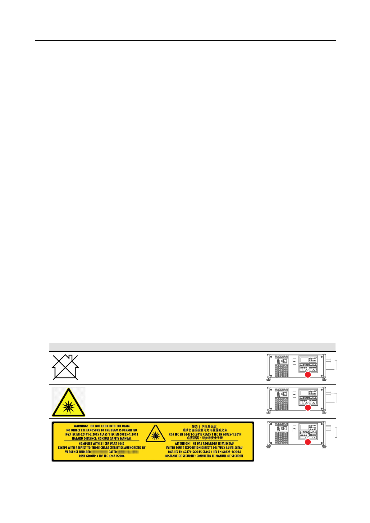
Light beam related safety labels
Label image Label description Label location
Hazard RG3: not for household use symbol.
Hazard RG3: optical radiation warning symbol.
WARNING! DO NOT LOOK INTO THE LIGHT BEAM NO DIRECT EYE EXPOSURE TO
THE BEAM IS PERM ITTED. RG3 IEC EN 62471 –5:2015. CLASS 1 IEC E N 60825–1:2014.
HAZARD DISTANCE: CONSULT SAFETY MANUAL.
R5906112 UDX SERIES 24/05/2017 7
Page 12
1. Safety
Label image Label description Label location
COMPLIES WITH 21 CFR 1040 EXCEPT WITH RESPECT TO THOSE CHARACTERISTICS
AUTHORIZED BY VARIANCE NUMB E R xxxx-x-xxxx DATED mm dd, yyyy RISK GROUP 3
LIP IEC 62471:2006.
警告! 勿观看光束 眼睛勿直接接触可允许暴露的光束 (RG3 IEC EN 62471-5:2015 CLASS 1
IEC EN 60825-1:2014) 危害距离:请参考 安全手册
DANGER ! NE PAS REGARDER LE FAISCEAU EVITER TOUTE EXP OSIT ION DIRECTE
DES YEUX AU FAISCEAU. RG3 IEC EN 62471-5:2015. CLA SS 1 IEC EN 60825-1:2014.
DISTANCE DE SECURITE : CONSULTER LE MANUEL DE SECURITE.
1.4 High Brightness p recautions: Hazard Distance (HD)
HD
Hazard Distance (HD) is the distance measured from the projection lens at wh ich the intensity or the energy per surface
unit becomes lower than the applicable exposure limit on the cornea or on the skin. The light beam is considered (to
be) unsafe for exposure if the distance from a person to the light source is less than the HD.
Restriction Zone (RZ) based on the HD
The HD depends on the amount of lumens produced by the projector and the type of lens installed. S ee next chapter"HD in function
of m odifying optics", page 11.
To protect untrained end users (as cinem a visitors) the installation shall comply with the following installation requirements: O per ators shall control access to the beam within the hazard distance or install the product at the height that w ill prevent spectators’ eyes
from being in the hazard distance. Radiation levels in excess of the limits will not be permitted at any point less than 2.0 meter (SH)
above any surface upon wh ich persons other than operators, performers, or em ployees are permitted to stand or less than 1.0 meter
(SH) lateral separation from any place where such persons are permitted to be. In non-cinema environments w here unrestrained
behavior is reasonably foreseeable, the minimum separation height s hould be greater than or equal to 3.0 meter to prevent potential
exposure, for example by an individual sitting on another individual’s shoulders, within the H D.
These values are minimum values and are based on the guidance provided in IEC 62471-5:2015 section 6.6.5.
The end user must understand the risk and apply protective measu
in the user information. Installation method, bar riers, detection sy stem or other applicable control measure shall prevent hazardous
eye access to the radiation within the hazard distance.
For example, pro jectors that have a HD greater than 1 m and emit light into an uncontrolled area where persons may be present
should be positioned in accordance with “the fixed projector installation” parameters, resulting in a HD that does not extend into
the audience area unless the beam is at least 2.0 meter above the floor level. In non-cinema environments w here unrestrained
behavior is reasonably foreseeable, the minimum separation height s hould be greater than or equal to 3.0 meter to prevent potential
exposure, for exam ple by an individual sitting on a nother individual’s shoulders, within the HD. For example, a sufficiently large
separation height may be achieved by mounting the image projector on the ceiling or through the use of physical barriers.
For applications installed in the USA market the above limits do not apply. The relevant minimum separation height is 2.5 meter (8.2
ft) and the separation width is defin ed as 1.0 meter (3.3 ft) by the FDA CDRH.
res based upon the hazard distance as indicated on the label and
RA TH
HD
RA
SH
RZ
SH
Image 1-1
ASideview.
B Top view.
RA Restricted Access location (boot area of projector).
PR Projector.
8 R5906112 UDX SERIES 24/05/2017
PR
(B) TOP VIEW(A) SIDE VIEW
TH
HD
SW
SW
SW
RZ
1m
SW
Page 13
1. Safety
TH Theater.
RZ Restriction Zone in the theater.
SH Separation Height.
SW S eparation Width.
Based on national requirements, no person is allowed to enter the projected beam within the zone between the projection lens and
the related hazard distance (HD). This shall be physically impossible by creating sufficient separation height or by placing barriers.
The minimum separation height takes into account the surface upon which persons other than operator, performers or employees
are per mitted to stand.
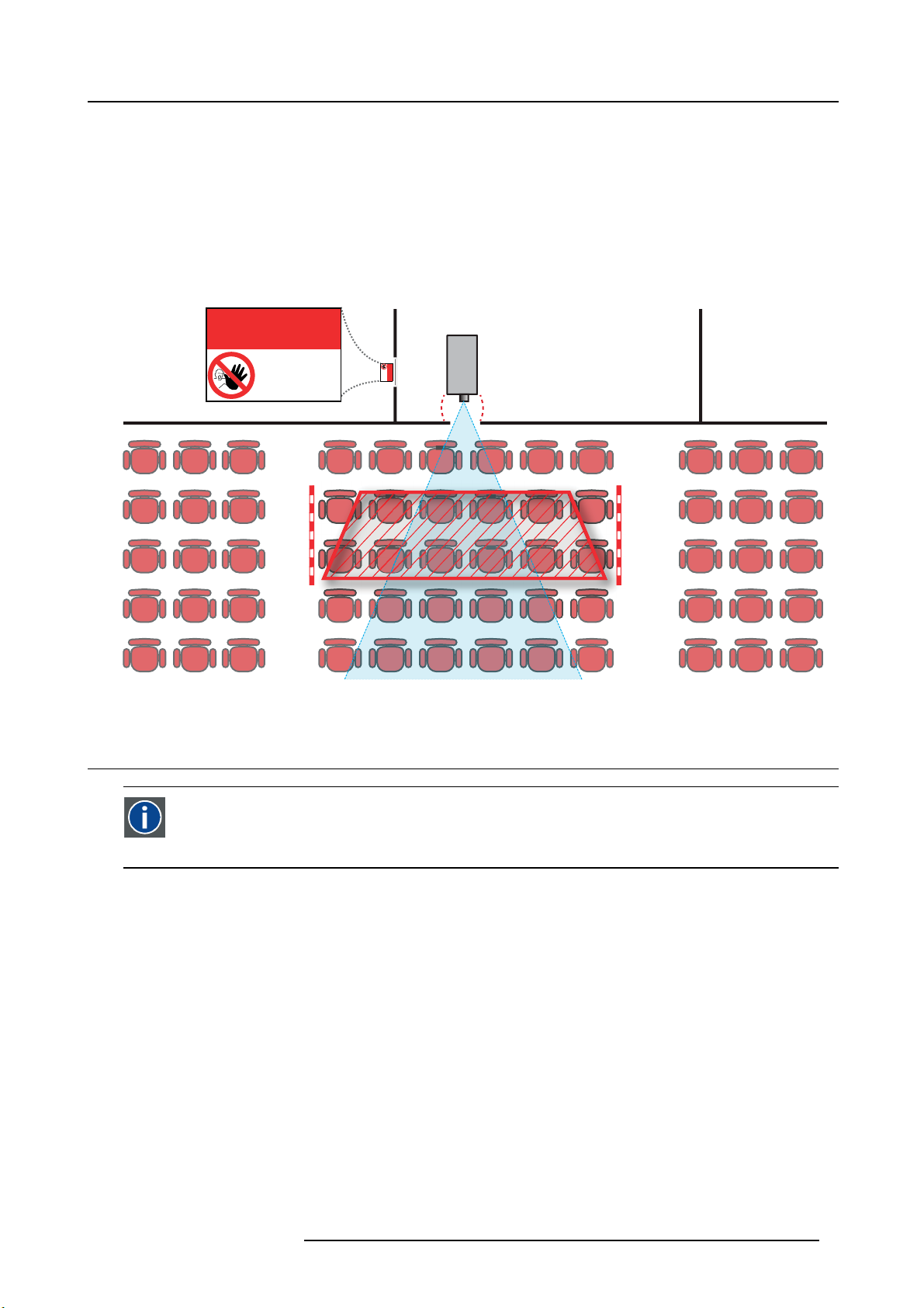
On image 1-2 a typical s etup is displayed. It must be verified if these minimum requirements are met. If required a restricted zone
(RZ) in the theater must be established. This can be do ne by using physical barrier, like a red rope as illustrated in image 1-2.
The restricted area s ticker can be replaced by a sticker with only the symbol.
RESTRICTED
AREA
AREA
RESTRICTED
PR
Image 1-2
1.5 HD for fully enclosed projection systems
HD
Hazard Distance (HD) is the distance measured from the projection lens at wh ich the intensity or the energy per surface
unit becomes lower than the applicable exposure limit on the cornea or on the skin. The light beam is considered (to
be) unsafe for exposure if the distance from a person to the light source is less than the HD.
Restriction Zone (RZ) based on the HD
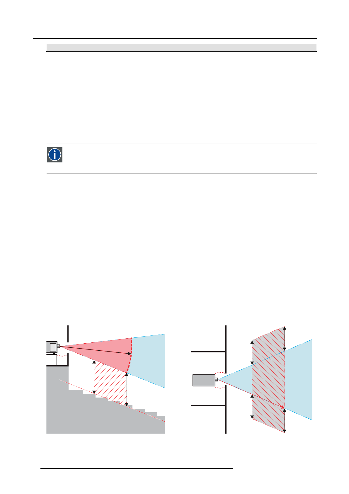
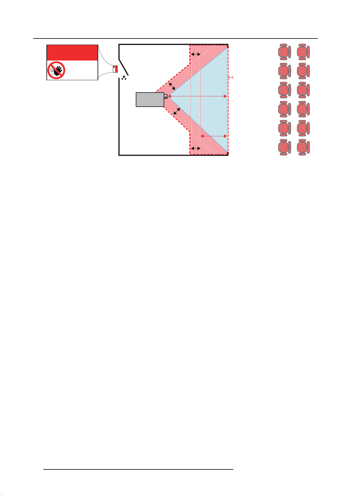
The projector is also suitable for rear projection applications; projecting a beam onto a defuse co ated projection screen. As displayed
in image 1-3 two areas should be considered: the restricted enclosed projection area (RA) and the observation area (TH).
R5906112 UDX SERIES 24/05/2017
9
Page 14
1. Safety
RESTRICTED
RA TH
sw
AREA
RESTRICTED
AREA
HDDIFFUSE
RZ
sw
sw
PD
HD
REFLECTION
reflection
); also taking into account a 1 meter lateral
PR
sw
Image 1-3
RA Restricted Access location (enclosed projection area).
PR Projector.
TH Theater (observation area).
RZ Restriction Zone.
PD Projection Distance.
SW Separation Width. Must be minimum 1 meter.
For this type of setup 3 different HD shall be considered:
• HD as discussed in "High Brightness precautions: Haz ard Distance (HD)", page 8 , relevant for intrabeam exposure.
•HD
•HD
: the distance that has to be kept restrictive related to the reflected light from the rear projection screen.
reflection
: the relevant distance to be considered while
diffuse
observing the defuse surface of the rear projection screen.
As des cribed in "High Brightness precautions: Hazard Distance (HD)", page 8 , it is mandatory to create a restricted z one within
the beam areas closer than any NOHD. In the enclosed projection area the combination of two restricted zones are relevant: The
restricted zone of the projected beam toward the screen; taking into account 1 meter Separation Width (SW) from the beam onward.
Combined with the restricted zone related to the rear reflection from the screen (HD
separation.
The HD
projection s creen. To determine the HD distance for the used lens and projector model see graphs in chapter "HD in function of
distance equals 25% of the difference between the determined HD distance and the projection distance to th e rear
reflection
modifying optics", page 11.
HD
reflection
= 25% (HD – PD)
The light emitted from the screen within the observation shall never exceed the RG2 exposure limit, determined at 10 cm. The
HD
can be neglected if the meas
diffuse
ured light at the screen surface is below 5000 cd/m² or 15000 LUX.
10
R5906112 UDX SERIES 24/05/2017
Page 15
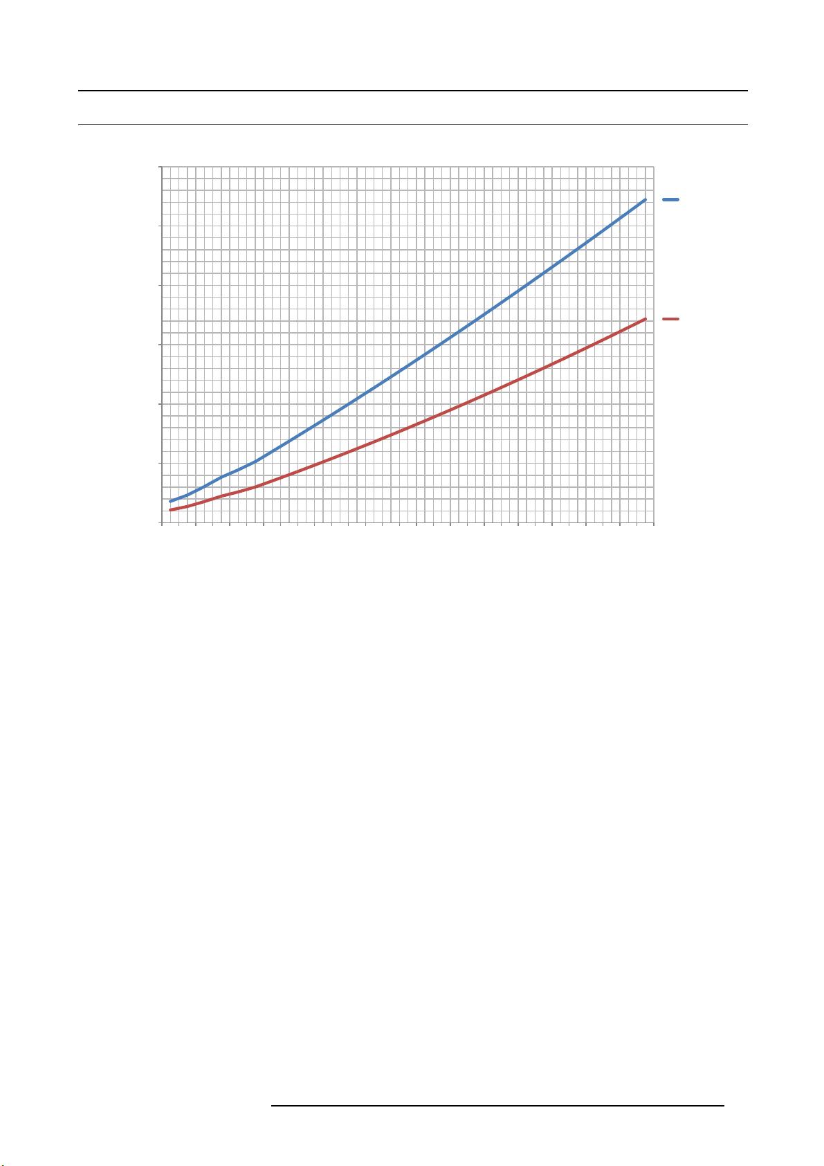
1.6 HD in function of modifying optics
Hazard Distance
12,00
10,00
8,00
6,00
Hazard Distance [m]
4,00
2,00
1. Safety
UDX 4K32
UDX U32
UDX W32
UDX 4K22
UDX W22
0,00
Image 1-4
0,5
0,9
1,3
1,7
2,0
2,3
2,7
3,1
3,5
3,9
4,3
4,7
5,1
Throw Ratio
5,5
5,9
6,3
6,7
7,1
7,5
7,9
8,3
8,7
9,1
9,5
9,9
10,3
10,7
11,1
11,5
R5906112 UDX SERIES 24/05/2017 11
Page 16

1. Safety
12 R5906112 UDX SERIES 24/05/2017
Page 17
2. Remote Control Unit
2. REMOTE CONTROL UNIT
2.1 Remote control, Battery installation
Where to fi nd the batteries for the remote control ?
The batteries are not placed in the remote control unit to avo id control operation in its pac kage, r
time. At delivery the batteries can be found in a separated bag attached to the remote control unit. Before using your remote control,
install the batteries first.
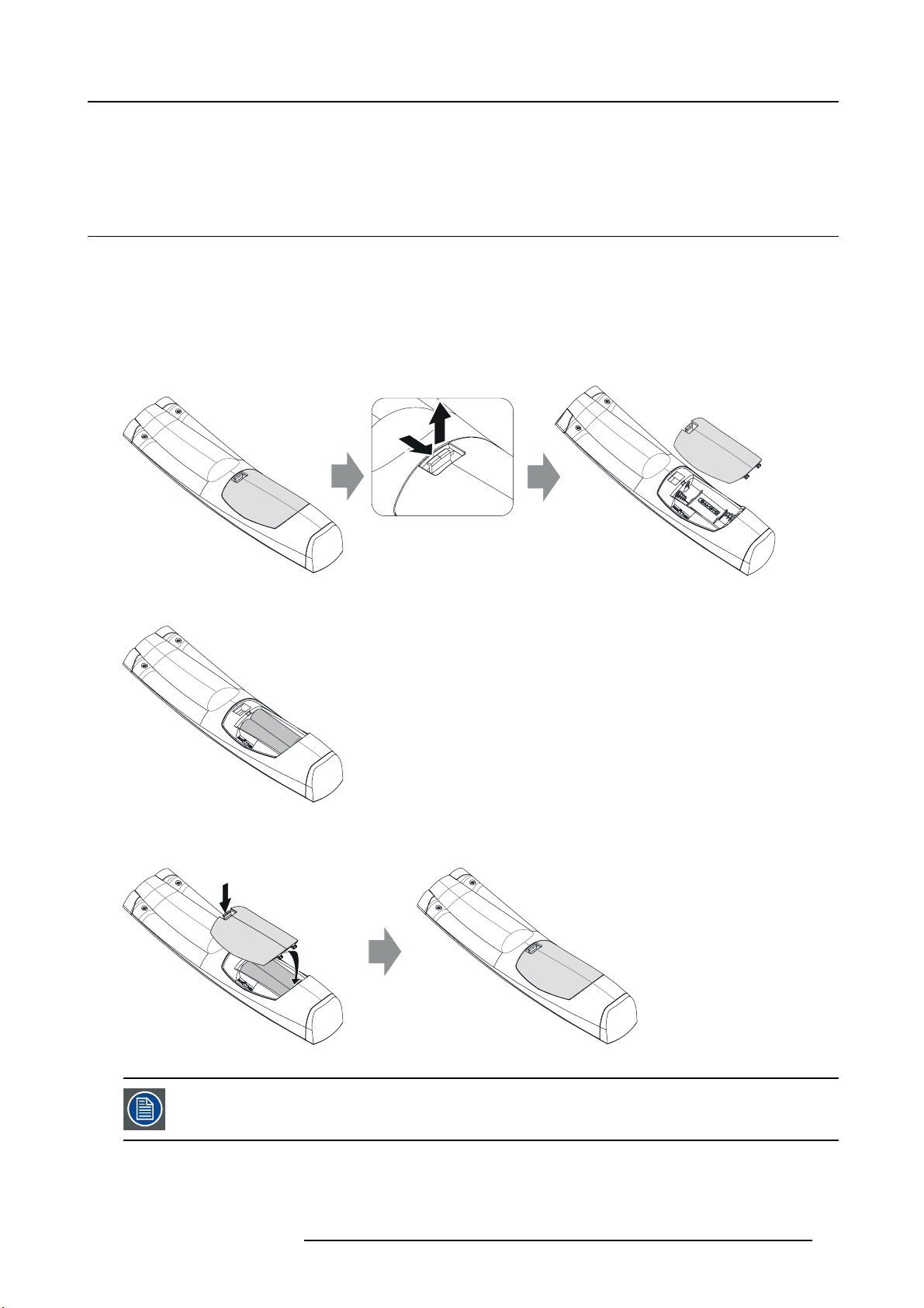
How to install
1. Push the battery cover tab with the fingernail a little backwards (1) and pull, at the same time, the cover upwards (2).
esulting in a shorter battery life
1
Image 2-1
2. Insert the two A A size batteries, m aking sure the polarities match the + and - marks inside the battery compartment.
+
-
-
+
Image 2-2
3. Insert (1) both lower tabs of the battery cover in the gaps at the bottom of the remote control, and press (2) the cover until it clicks
in place.
2
2
+
-
Image 2-3
When replacing batteries, the broad cast address of the RCU will be reset to its default value ’0’.
R5906112 UDX SERIES 24/05/2017 13
1
-
+
Page 18
2. Remote Control Unit
CAUTION: Replace w ith the correct battery type. Use two AA size batteries. There is a risk of explosion if the
battery is replaced with an incorrect type.
CAUTION: Rep lace the battery as explained above . There is a risk of explosion if the battery is incorrectly
installed.
2.2 Using the XLR connector of the RCU
Connecting a cable with the XLR connector will rese t the broadcast address of the RCU to its default value ’0’.
How to use the XLR connector
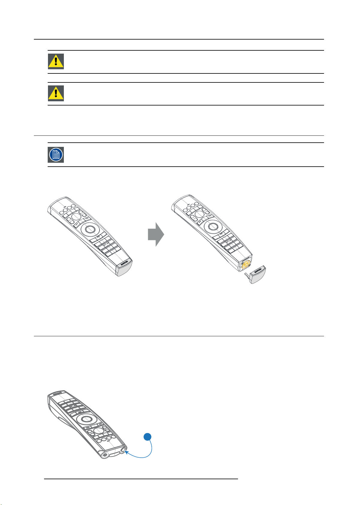
1. R emov e the XLR cover by pulling it backwards.
Image 2-4
2. C onnect a cable with XLR plug into the XLR connector of the RCU.
3. C onnect the other end of the c able with the XLR inpu
t of the projector.
2.3 Remote control, on/off button
Purpose of the remote control on/off button
The Pulse remote control unit has at the front side an on/off switch (reference 1 image 2-5). Switching off the remote control prevents
that unwanted commands are send due to an accidental key press. Furthermore, switching the RCU off will extend the battery life
time of the remote c ontrol.
To activate the re mote control press the on/off button.
To deactivate the remote control press the on/off button again.
1
Image 2-5
14 R5906112 UDX SERIES 24/05/2017
Page 19
3. Input & Communication
3. INPUT & COMMUNICATION
3.1 Introduction
General
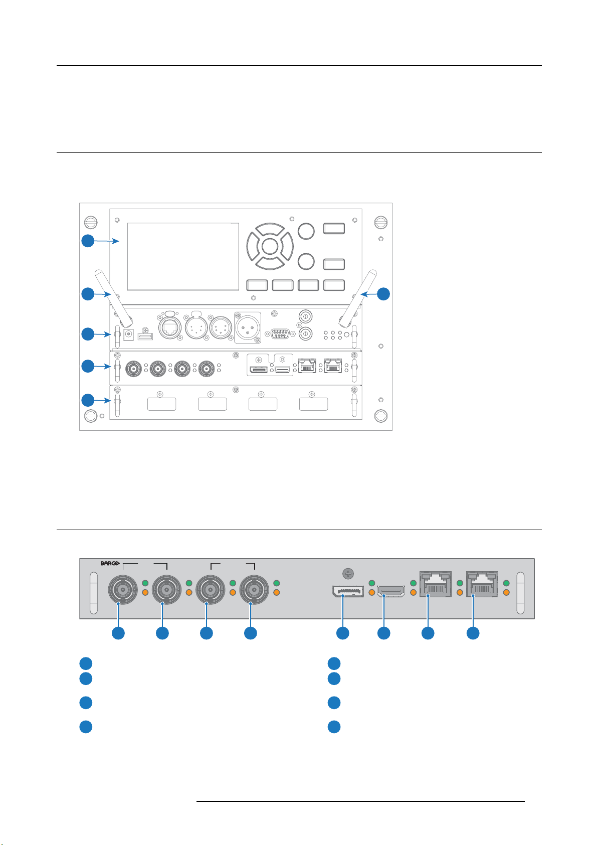
The Input & Communication side of the pr ojector consists of a local keypad, a communication panel, a
(V&H) and a free input slots. The free input slot can be used for optional modules (e.g. Virtual & Au gmented Reality Input (V&AR)).
1
2 3
4
venues & hospitality Input
5
6
Image 3-1
1 Local K eypad and touch panel
2 Optional antenna for WiFi connection
3 Optional antenna for GSM
4 Communication Panel
5 Venues & Hospitality Input (V&H)
6 Free input slot (here filled with the V &AR module)
3.2 Input source connections
Venues & Hospitality Input (V&H)
SDI IN SDI IN/OUT
SEL
SYNC
A
1 2 3 4 5 6 7 8
Image 3-2
SEL
SYNC
B
C
SEL
SYNC
SEL
SYNC
D
SEL
DP
SYNC SYNC
HDM I
SEL
HDBT 1
SEL
SYNC
HDBT 2
SEL
SYNC
Quad 3G SDI channel A Input
1
Quad 3G SDI channel B Input
2
Quad 3G SDI channel C Input
3
Quad 3G SDI channel D Input
4
The yellow LED lights up when valid input sync is detected.
The green LED lights up when the input is selected.
R5906112 UDX SERIES 24/05/2017
DisplayPort Input
5
HDMI Input
6
HDBaseT Input 1
7
HDBaseT Input 2
8
15
Page 20

3. Input & Communication
Input specifications
HDMI
Up to 297 MHZ pixel clock
YCbCr 4:4:4
For future release
• YCbCr 4:2:2 and YCbCr 4:2:0
• 3D support
• Interlaced s upport
• HDCP 1.4
• HDCP 2.2
HDMI 1.4a Support for ’Deep Color’ up to 12 bit per color
Audio not supported
Video timings
640 x 480 @60 Hz
720 x 480 @60 Hz
720 x 576 @50 Hz
800 x 600 @60 Hz
1024 x 768 @60 Hz
1280 x 720 @50 Hz
1280 x 720 @60 Hz
1280 x 800 @60 Hz
1280 x 960 @60 Hz
1280 x 1 024 @60 Hz
1400 x 1 050 @60 Hz
1600 x 1 200 @60 Hz
1920 x 1 080 @24 Hz
1920 x 1 080 @25 Hz
1920 x 1 080 @30 Hz
1920 x 1 080 @50 Hz
1920 x 1 080 @60 Hz
1920 x 1 200 @50 Hz
1920 x 1 200 @60 Hz
2048 x 1 080 @24 Hz
2048 x 1 080 @25 Hz
2048 x 1 080 @30 Hz
2048 x 1 080 @48 Hz
2048 x 1 080 @50 Hz
2048 x 1 080 @60 Hz
2560 x 1 600 @50 Hz
2560 x 1 600 @60 Hz
16
3840 x 2 160 @24 Hz
3840 x 2 160 @25 Hz
3840 x 2 160 @30 Hz
3840 x 2 160 @50 Hz
3840 x 2 160 @60 Hz
4096 x 2 160 @24 Hz
R5906112 UDX SERIES 24/05/2017
Page 21

HDMI
4096 x 2 160 @25 Hz
4096 x 2 160 @30 Hz
4096 x 2 160 @50 Hz
4096 x 2 160 @60 Hz
HDBase-T
25 – 297 MHz pixel clock
Colors
• YCbCr 4:2:2
• YCbCr 4:4:4
• Color 24 bpp
• Color 30 bpp
• Color 36 bpp
For future release
• 3D support
• Interlaced support
•HDCP1.4
Audio not supported
Video timings
640 x 480 @ 60 Hz
720 x 480 @ 60 Hz
720 x 576 @ 50 Hz
800 x 600 @ 60 Hz
1024 x 768 @ 60 Hz
1280 x 720 @ 50 Hz
1280 x 720 @ 60 Hz
1280 x 800 @ 60 Hz
1280 x 1024 @ 60 Hz
1400 x 1050 @ 60 Hz
1600 x 1200 @ 60 Hz
1920 x 1080 @ 24 Hz
1920 x 1080 @ 25 Hz
1920 x 1080 @ 30 Hz
1920 x 1080 @ 50 Hz
1920 x 1080 @ 60 Hz
1920 x 1200 @ 50 Hz
1920 x 1200 @ 60 Hz
2048 x 1080 @ 24 Hz
2048 x 1080 @ 25 Hz
3. Input & Communication
2048 x 1080 @ 30 Hz
2048 x 1080 @ 48 Hz
2048 x 1080 @ 50 Hz
2048 x 1080 @ 60 Hz
2560 x 1600 @ 50 Hz
2560 x 1600 @ 60 Hz
3840 x 2160 @ 24 Hz
3840 x 2160 @ 25 Hz
R5906112 UDX SERIES 24/05/2017
17
Page 22

3. Input & Communication
HDBase-T
3840 x 2160 @ 30 Hz
4096 x 2160 @ 24 Hz
4096 x 2160 @ 25 Hz
4096 x 2160 @ 30 Hz
SDI
3G SDI follows the S MP TE 425M standard Level A
HD-SDI follows the SMPTE 292M standard
Color space YCbCr
RGB : future release
Color depth
10 bpc
12 bpc : future release
Chroma sampling
Audio support not supported
3D sup port
Video timings
Progressive
4:2:2 only
4:2:0 and 4:4:4 : future release
For future release
• Interlaced support
• Segmented frame support
Type Port type Format
HD-SDI Single link 1280 x 720 @ 24 Hz
HD-SDI Single link 1280 x 720 @ 25 Hz
HD-SDI Single link 1280 x 720 @ 30 Hz
HD-SDI Single link 1280 x 720 @ 50 Hz
HD-SDI Single link 1280 x 720 @ 60 Hz
HD-SDI Single link 1920 x 108 0 @24 Hz
HD-SDI Single link 1920 x 108 0 @25 Hz
HD-SDI Single link 1920 x 108 0 @30 Hz
3G-SDI Level A Single link 1920 x 1080 @50 Hz
3G-SDI Level A Single link 1920 x 1080 @60 Hz
3G-SDI Level A Single link 2048 x 1080 @50 Hz
3G-SDI Level A Single link 2048 x 1080 @60 Hz
3G-SDI “BarcoLink” Single link 1920 x 120 0 @50 Hz
3G-SDI “BarcoLink” Single link 1920 x 1200 @59.94 Hz
3G-SDI “BarcoLink” Single link 1920 x 120 0 @60 Hz
DisplayPort
Up to 600 MHz pixel clock
Colors
3D sup port
18
• YCbCr 4:4:4
• YCbCr 4:2:2
Field sequential 3D (active 3D)
R5906112 UDX SERIES 24/05/2017
Page 23

DisplayPort
For future release:
• Passive 3 D support
• Interlaced support
•HDCP1.4
Audio not supported
DP 1.2 Support for ’Deep Color’ up to 12 bit per color
Bitrate Support
• Reduced Bit R ate (RBR)
•HighBitRate(HBR)
• High Bit Rate 2 (HBR2)
Video timings
640 x 480 @ 60 Hz
800 x 600 @ 60 Hz
960 x 2160 @ 120 Hz
960 x 2400 @ 120 Hz
1024 x 768 @ 60 Hz
1024 x 2160 @ 120 Hz
1280 x 800 @ 60 Hz
1280 x 960 @ 60 Hz
1280 x 1024 @ 60 Hz
1400 x 1050 @ 60 Hz
1600 x 1200 @ 60 Hz
1920 x 1080 @ 24 Hz
1920 x 1080 @ 30 Hz
1920 x 1080 @ 50 Hz
1920 x 1080 @ 60 Hz
1920 x 1200 @ 50 Hz
1920 x 1200 @ 60 Hz
1920 x 1200 @ 120 Hz
1920 x 2160 @ 60 Hz
1920 x 2160 @ 120 Hz
2048 x 1080 @ 24 Hz
2048 x 1080 @ 25 Hz
2048 x 1080 @ 30 Hz
2048 x 1080 @ 48 Hz
2048 x 1080 @ 50 Hz
2048 x 1080 @ 60 Hz
2048 x 1080 @ 120 Hz
2560 x 1600 @ 50 Hz
2560 x 1600 @ 60 Hz
3840 x 2160 @ 24 Hz
3840 x 2160 @ 25 Hz
3840 x 2160 @ 30 Hz
3840 x 2160 @ 50 Hz
3840 x 2160 @ 60 Hz
3. Input & Communication
R5906112 UDX SERIES 24/05/2017
19
Page 24
3. Input & Communication
DisplayPort
3D Su pport
CAUTION: In order to display high resolution images (ex.: 3840X2160@60Hz) via the DP1.2 input, the quality
of the cable must be adequate, in addition the length of the cable can also influence the performance. In case
there is an issue with one of the se criteria the automatic link-training i nitiated by the DP-standa rd may deci de
to switch to a lower resolution.
3840 x 2400 @ 50 Hz
3840 x 2400 @ 60 Hz
4096 x 2160 @ 24 Hz
4096 x 2160 @ 30 Hz
4096 x 2160 @ 50 Hz
4096 x 2160 @ 60 Hz
1280 x 720 @ 50 Hz
1280 x 720 @ 60 Hz
1920 x 1080 @ 50 Hz
4096 x 2160 @ 24 Hz
CAUTION: The HDBaseT inputs can bridge a distance of 100 m but is sensitive to radiated electromagnetic
interference: rad iated electromagnetic interference (e.g. from GSM or switching inductive or capacitive loads)
within the limits of electromagnetic compatibility requirements of 3 V/m ca n cause random flashes or temporary loss of the projected image.
As suc h, shielded CAT-6 cables with metal RJ-45 connecto
than required and route HDBT cable optimally screened from possible sources of electromagnetic emission.
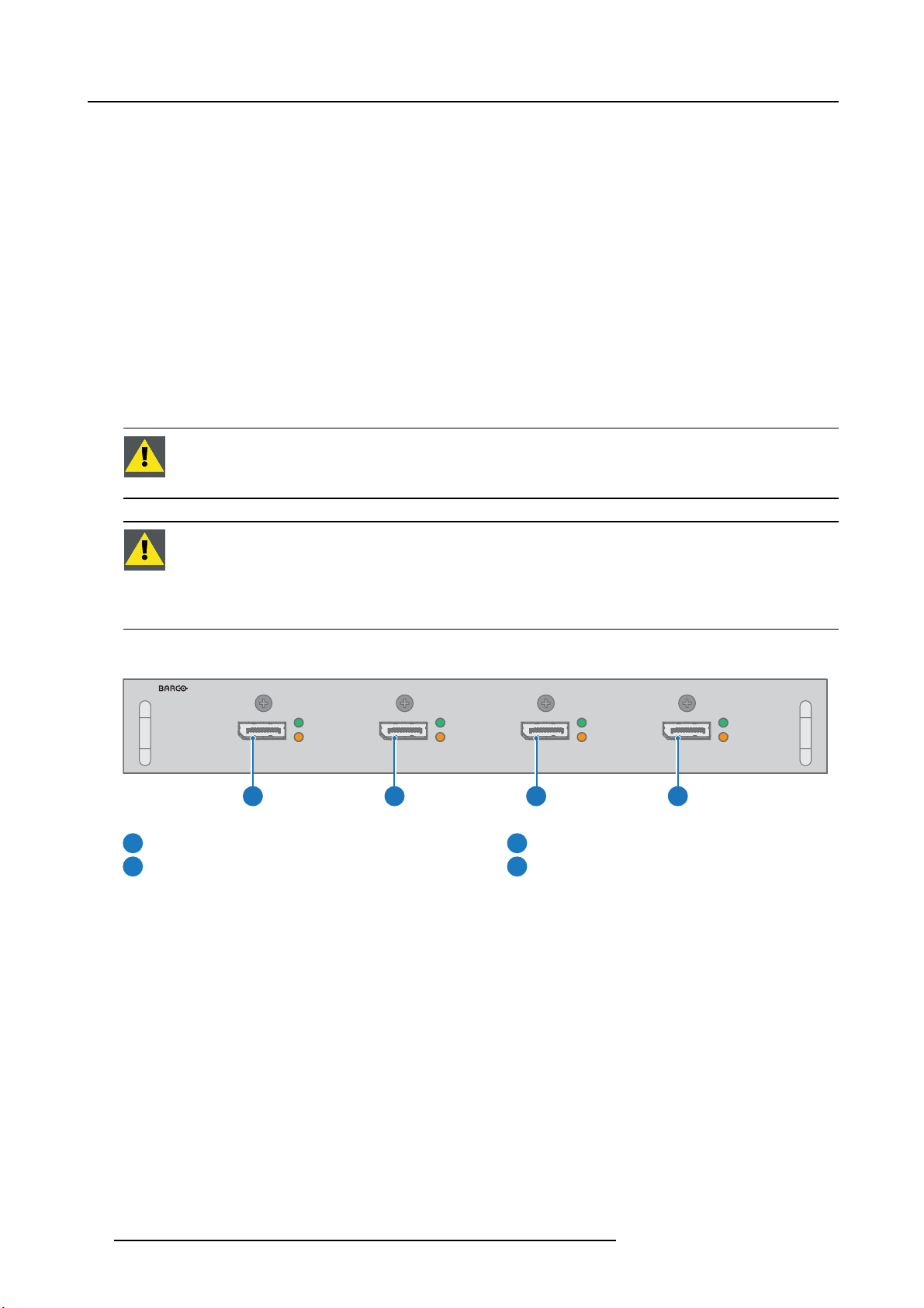
Virtual & Augmented Reality Input (V&AR) (Optional)
SEL
DP A
SYNC
1 2 3 4
Image 3-3
Quad DisplayPort channel A Input
1
Quad DisplayPort channel B Input
2
The yellow LED lights up when valid input sync is detected.
The green LED lights up when the input is selected.
DP B
SEL
SYNC
Input specifications
All inputs are DisplayPort 1.2 .
rs are recommended; choose cable length no longer
SEL
DP C
SYNC
Quad DisplayPort channel C Input
3
Quad DisplayPort channel D Input
4
DP D
SEL
SYNC
DP
Up to 600 MHz pixel clock
YCbCr 4:4:4
Audio not supported
20
For future release
• YCbCr 4:2:2 and YCbCr 4:2:0
• 3D support
• Interlaced support
•HDCP1.4
R5906112 UDX SERIES 24/05/2017
Page 25

DP
3. Input & Communication
DP 1.2
Video timings
Support for ’Deep Color’ up to 12 bit per c olor
640 x 480 @ 60 Hz
720 x 480 @ 60 Hz
800 x 600 @ 60 Hz
1024 x 768 @ 60 Hz
1280 x 720 @ 50 Hz
1280 x 720 @ 60 Hz
1280 x 960 @ 60 Hz
1280 x 1024 @ 60 Hz
1400 x 1050 @ 60 Hz
1920 x 1080 @ 24 Hz
1920 x 1080 @ 30 Hz
1920 x 1080 @ 50 Hz
1920 x 1080 @ 60 Hz
1920 x 2160 @ 60 Hz
2560 x 1600 @ 60 Hz
3840 x 2160 @ 24 Hz
3840 x 2160 @ 30 Hz
3840 x 2160 @ 60 Hz
4096 x 2160 @ 24 Hz
4096 x 2160 @ 30 Hz
3.3 Communication connections
Communication Panel
321 4 5 6 7 8 9 10 11 12 13
Image 3-4
WIFI antenna for wireless IP ( optional)
1
12V 1A output
2
Firmware update / USB backup custom settings
3
4
10/100 base-T for external control over IP and Art-Net
DMX interface input
5
DMX interface output
6
XLR input for wired projector control
7
12V output
12 V output, maximum 1A, available when projector is not in stand by.
8
RS232 for serial c omm unication
Sync Out 3D
9
Sync In 3D
10
Status lights
11
12
IR receive sensor
GSM antenna input (optional)
13
R5906112 UDX SERIES 24/05/2017
21
Page 26

3. Input & Communication
DMX interface
DMX is used as communica tion bus between different devices in the light technic. Each device has an input and an output, so that
the bus can be looped between the different devices. According the standard a five wire cable with XLR connector is used.
You can use the DMX input port to connect a DMX device (DMX console) to the projector. T his way you can control the projector
from that DM X device (console). The DMX output port can be connected with the next device in the loop.
Pin Description
1Earth
2
3Hot
4
5
DMX
DMX-512 Lighting protocol over RS-485 interface. Carries information of 512 channels from a lighting controller to
lighting devices. Standardized by USITT.
Cold
Return - (or not used)
Return + (or not used)
RS232/RS422 input
The communication interface of the U DX supports RS232 and RS422 serial communication on two different types of input connectors, a Sub-D connector and an USB connector acting as RS input when connected to an USB input of a PC.
You can use the RS232/RS422 input to connect a local PC to your UDX . By this way you can configure and control your UDX from
your local PC.
Advantages of using RS232/RS422 serial communication:
• easy adjustmen t of the projector via PC (or MAC).
• allow storage of multiple projector confi gurations and set ups.
• wide range of control poss ibilities.
• address range from 0 to 255.
• sending data to the projector (update).
• copying data from the projector (backup).
RS232/422 input (Sub-D) port
Pin Description
1
DCD : Data Carrier Detect
2RXD-:ReceiveData
3 TXD- : Transmitted Data
4
DTR : Data Terminal Ready [RS232]
TXD+ : Transmitted Data [RS422]
5
GND : Ground
6
DSR : Data Set Ready [RS232]
RXD+ : Received Data [RS422]
7
— (not con nected) —
8
CTS : Clear To Send
9 RI : Ring Indicator
RS232
An Electronic Industries Association (EIA) serial digital interface standard specifying the characteristics of the comm unication path between two devices using either D-SUB 9 pins or D-SUB 25 pins connectors. This standard is used for
relatively short-range com munications and does not specify balanced control lines. R S-232 is a serial control standard
with a set number of conductors, data rate, word length and type of connector to be used. The standard specifies component connection standards with regard to computer interface. It is also called RS-232-C, which is the third version
of the RS-232 standard, and is functionally identical to the CCITT V.24 standard. Logical ’0’ is > + 3V, Logical ’1’ is < 3V. The range between -3V and +3V is the transition zone.
22 R5906112 UDX SERIES 24/05/2017
Page 27

3. Input & Communication
RS422
An EIA serial d igital interface standard that specifies the electrical characteristics of balanced (differential) voltage,
digital interface circuits. This standard is us able ov er longer distances than RS-232. This signal governs the asynchronous transmission of computer data at speeds of up to 920,000 bits per second. It is also used as the serial port
standard for Macintosh computers. W hen the difference between the 2 lines is < - 0.2V that equals with a logical ’0’.
When the difference is > +0.2V that equals to a logical ’1’..
USB port
The com munication interface is equipped with a master USB port, type “A” connector. This USB port will simplify the service procedures for software updates or for taking backup files from the projector without network connection. A n USB-stick is plugged into
the USB port and files can be transferred from or to the projector using the local or remote control unit. Note that the USB-stick has
to be Linux FAT16 compatible.
3.4 LED and Button indication chart
Button Backlight Status
Button Color status Description
Standby button
Shutter button
Blinking WHITE (slow) Projector starts up (booting)
Blinking WHITE (fast) Firmware upgrade
Solid W HIT E Projector is in Standby mode
Blinking BLUE Projector goes to ON mode
Solid BLUE Projector is ON
Blinking RED Error condition
Off (no color) Projector is OFF, starts up, or is in Standby
mode.
Solid W HIT E Projector is ON, shutter is open
Solid RED Projector is ON, shutter is closed
LED Status
LED
PWR (power LED)
LIGHT (Illumination LED)
Color status
Off
RED
ORANGE
GREEN
Off Light source is off
RED No light source d etected
ORANGE Light source is on in ECO mode
GREEN
GREEN-ORANGE Light source is on in CLO mode
Description
Projector powers up
Projector is in S tandby
Projector is Ready
Projector is on
Light source is on in normal mode
R5906112 UDX SERIES 24/05/2017 23
Page 28

3. Input & Communication
LED
ERR (error LED)
Color status
Off
RED toggles on/off
ORANGE toggles on/off
RED IR signal receivedIR
GREEN IR signal acknowledged
Description
No error
Error
Warning
24 R5906112 UDX SERIES 24/05/2017
Page 29

4. Getting Started
4. GETTING STARTED
How controlling the projector ?
The projector can be controlled by the local keypad, by the remote control unit o r by browser application.
Location of the local keypad ?
The local keypad is located on the input side of the projector.
Remote control functions.
This remote control includes a battery powered infrared (IR) transmitter that allows the user to control the projector remotely. This
remote control is used for source selection, control, adaptation and set up.
Other functions of the remote control are :
• switching between stand by and operational m ode.
• switching to "pause" (blanked picture, full power for immediate restarting)
• direct access to all connected sources.
Overview
• Functionality overview
• Power on projector
• Switching to standby
• Power off projector
• Using the RCU
• Projector A ddress
• Quick setup via Direct a ccess
4.1 Functionality overview
Local Keypad overview
1
Menu S election.
2
Menu Activation, OK button
3
OSD On/Off.
4
Menu Back.
5
Power On/Off.
6
Touch Panel On/Off.
7
Input Selection.
8
Shutter Open/Close.
9
Test Patterns.
10
Lens Menu.
11
Touch Panel.
The Keypad gives direct access to several funct
The keypad has a back light that can be switched on and off manually. The light turns off automa tically after a preselected time.
The keys are equipped with white and blue backlit L EDs. Power button is equipped with white, blue and red backlit. The LEDs are
controlled according to the features available.
ions, in addition to access to the m enu system.
1 2 3 4 5 6
1011 9 8 7
R5906112 UDX SERIES 24/05/2017
25
Page 30

4. Getting Started
Remote Control Unit buttons
1
2
3
4
5
6
7
8
9
10
11
12
13
14
15
24
23
22
21
20
19
18
17
16
1
Button pressed indicator.
2
Shutter Open.
3
Shutter Close.
4
Touch Panel On/Off.
5
OSD On/Off.
6
Lens Zoom .
7
Lens Shift.
8
Menu Activation.
9
Menu Selection, O K button.
10
Menu Navigation.
11
Input Selection.
12
Address button.
Numeric buttons.
13
Backspace (while entering
14
values)
XLR connector.
15
Decimal mark (while entering
16
values)
Macro button.
17
Menu Back.
18
Default button.
19
Lens Focus.
20
Color On/Off.
21
Test Patterns.
22
Power On.
23
Power Off.
24
Stereo Jack.
25
RCU On/Off.
26
2625
The projector remote control is a full feature wireless remote control, powered by two (2) standard AA batteries. The battery compartment is on the back side of the remote control.
The remote control is backlit for use in dark environments. It also has an XLR connector for wired connection to the projector. When
the wire is connected, the IR beam is s witched off.
LCD panel
The LCD pan el has two main functions:
1. Showing the menus and adjustment information. and also a mirror of the O SD, (On Screen Display) described in User Interface
when this is enabled.
2. Information regarding the status of the projector showing this data:
- Projector status
- Network address
- Active source
- Current firmware version
- Operation Data
- Active functions (Enabled Functions).
Toggle between the two indications by using the Menu button on the keypad, or on the remote control
The LCD Display will fade out 30 seconds after the last key operation.
4.2 Power on projector
How to power on
1. Pres s the mains switch at the side of the projector to sw itch on this projector.
26
R5906112 UDX SERIES 24/05/2017
Page 31

4. Getting Started
Image 4-1
Mains switch
- When ’0’ is pressed, the projector is switched off.
- When ’I’ is pressed, the pr ojector is switched on.
The p rojector starts up to standby mode. The Power on/off button will blink until standby mode is ac hieved. Once in standby
mode, the Power on/off button will be lit WHITE, but the display will be off.
2. Pres s the Po w er on/off button on the projector, or the Power On button on the remote control.
The projector will continue to power on mode. T he Power on/off button will blink until the projector is rea dy. Once the projector
is rea dy, the P ower button will be lit B L UE.
The start up screen is displayed on the touch panel and when fully started up, it changes to the overview screen.
1
2
Image 4-2
The current mains input voltage is indicated on the voltmeter just above the power switch.
The background image of the startup screen an d info screens can be chang ed with Projector Toolset with an
installed UDX plug-in.
Status overview
Once the projector is started, press Status to get an overview of parameters such as :
• Device s erial number and article number
• Current firmware version and model name
• Current illumination (in percentage)
• Projector runtime in hours
• Uptime in hours
• Chosen source
• Current resolution and refresh rate
• Chosen communication method and IP address (if connected)
• Active functions
R5906112 UDX SERIES 24/05/2017
27
Page 32

4. Getting Started
Starting image projection
1. M ake sure the available sources are connected to the app ropriate input ports.
Tip: If properly connected, the “SYNC” LED will lit up ORANGE.
2. Pres s the Input Selection button on the keypad or on the remote control until:
- the LED of the selected source (the “SEL” LED) lit up GREE N, and
- the image of the selected s ource is projected.
1 2
Image 4-3
4.3 Switching to standby
How to switch to standby
1. Pres s and hold the Power on/off button for 3 seconds on the local keypad, or press the Power Off button on the rem ote control.
The projector goes to s tandby mode. The after-cooling cycle will start (about 30 seconds). During this period the Power on/off
button will blink. Once the after-cooling cycle has ended, the projector will be in standby mode and the Power on/off button will
be lit WHITE.
3 s
30 s
Image 4-4
4.4 Power off projector
CAUTION: This procedure assu mes the projector is in standby mode.
How to power off
1. Sw itch off the projector with the mains switch. ’0’ must be pressed.
28
R5906112 UDX SERIES 24/05/2017
Page 33

Image 4-5
2. U nplug the power cord from the projector.
4.5 Using the RCU
Pointing to the reflective screen
1. Point the front of the RCU to the reflec tive screen surface.
4. Getting Started
Image 4-6
IR control via reflective screen
Hardwired to the XLR input
1. Plug one end of the remote cable in the connector on the bottom of the RCU.
2. Plug the other end in the big connector on the communication interface of the projector, labelled Remote CTRL.
Note: Plugging the rem ote control will switch the broadcast address of the remote control to the d efault value ’0’. This is the
only broadcast address that will work when hardwired. If you want to change the broadcast address after disconnecting
the remote control, see "Projector Address", page 30.
Pointing directly to the IR sensor
When using the wireless remote control, m a ke sure you are within the effective operating distance (30 m, 100 ft in a straight line).
The remote control unit will not function properly if strong light strikes the sensor window or if there are obstacles between the remote
control unit and the projector
R5906112 UDX SERIES 24/05/2017
IR sensor.
29
Page 34

4. Getting Started
45°
45°
Image 4-7
RCU to one of the IR sensors
45°
45°
45°
45°
4.6 Projector Address
Projector address
Address installed in the pro jector to be individually controlled.
Broadcast address
Projector will always execute the com mand coming from a RC U programmed w ith that broadcast address.
4.6.1 Controlling the projector
Why a projector address?
As more than one projector can be installed in a room, each projector should be separately add ressable with an RCU or com puter.
Therefore each projector has its own address.
Set up an individual Projector Address
The set up of a projector address can be done via the software.
Projector controlling
Every projector requires an individual address between 0 and 255.
When the address is set, the pro jector can be controlled now:
• with the RCU: only for addresses between 0 and 31.
• with a computer: for any address between 0 a nd 255.
Broadcast Address
Every projector has a broadcast (common) address ’0’ or ’1’. The default address is ’0’.
The choice between ’0’ and ’1’ can be selected in the G UI: “System S ettings” → “Communication” →“IR Control “.
Placing new batteries in the remote control o r plugging the remote to a projector via XLR cable will automatically reset the address back to its default value ’0’.
30 R5906112 UDX SERIES 24/05/2017
Page 35

4.6.2 Displaying and Programming addresses into the RCU
Displaying the Projector Address on the Screen.
1. Pres s the Address button to see the projector address (proximately 2 seconds).
The pro jector ’s address is displayed on the LCD status screen.
How to Program an Address into the R CU?
1. Pres s the Address button until the Button pressed indicator lights up continuously (proximately 5 seconds).
2. En ter the address with the digit buttons within the time the indic ator lights up (also proximately 5 seconds).
Note: That address can be any value between 0 and 31.
Tip: A few examples:
To enter address 3, press "3" digit button on the RCU to set the RCU’s address to 3 and wait until the button pressed
indicator is out. Alternatively, you c an also press “0” and “3”. This way, he button pressed indicator goes out immediately.
To enter address 31, then press “3” and “1” on the digit button on the RCU and the button pressed indicator goes out
immediately.
4.7 Quick setup via Direct access
Quick source selection
1. Pres s the Input button on the remote c ontrol or local keypad.
4. Getting Started
Image 4-8
The source selection m enu opens.
Image 4-9
Input selection
2. U se the arrow keys to select the desired source.
I
I
R5906112 UDX SERIES 24/05/2017
31
Page 36

4. Getting Started
Quick test pattern selection
1. Pres s the Test pattern button on the remote c ontrol or local keypad.
P
Image 4-10
A first test pattern will be displayed.
2. Pres s as may times on that button until the des ired pattern is
P
displayed
32
R5906112 UDX SERIES 24/05/2017
Page 37

5. Graphic User Interface (GUI)
5. GRAPHIC USER INTERFACE (GUI)
Overview
•Overview
• Navigation
• Test Patterns
5.1 Overview
GUI - Main Menu overview
The projector on screen display (OSD) is the primary user interface (UI). From here, you can review and adjust all projector and
display settings.
The OSD interface uses tabs to display the main menu. Each main menu contains submenus.
The OS D can be disabled by pressing the OSD on/off button.
Image 5-1
Home menu
The projector’s software platform uses access levels what each user can do. A standard user has access to all projector functionality.
Acertified service technician has also access to the s ervice menu. This m enu is p assword protected.
5.2 Navigation
Navigation via the RCU or local keypad
Navigating the OSD can be done using the remote control or the loc al keypad.
1 4
2 3
3 2 1
4
Image 5-2
To start up the menu structure, press MENU (1).
R5906112 UDX SERIES 24/05/2017
33
Page 38

5. Graphic User Interface (GUI)
Use the arrow keys (Menu Navigation buttons) to navigate to the desired menu item (2). The background color changes to light
blue.
Press the Menu Selection button (center key of the arrow keys), also called OK button, to activate that item and to jump one level
deeper (3).
Use the numeral keys to enter values, or use the arrow keys to move t he bar scale up or down.
Press the Back button to go up one level ( 4).
Image 5-3
Home menu
Remark: a blue slider bar on the right side of the window means that there are m ore items to show than those currently displayed.
Define values
Menu settings are displayed using check boxes , bar scale sliders, and drop-down lists.
To se t a value:
•PressOK to select or deselect a checkbox (turn a function ON or OFF).
• Use the arrow keys to m ove the bar scale slider up or down on the value line. For a bar scale 0-9, each step will equal 1 0% of
the total value.
• To enter the value as a direct number, press OK, input the digit(s), and then press OK again to execute and exit cursor mode
e.g. OK 79 OK.
Within an input field, use the * button as backspace button to remove an e
Changes to values are implemented dynamically.
To enter values with the local keyboard, use the arrow keys to select the first digit, press OK. Select the second digit and press OK.
Continue until all digits are entered. Close the action by selecting the enter (↵) button and press OK. Select the backspace button
and press OK to remove the last entered digit.
ntered digit. Use the # button to enter a dot (.).
Menu memory
The OSD menu remembers the last selected sub-item as long as the projector is running. Th e menu memory is reset when res tarting
the projector from standby.
5.3 Test Patterns
How to use test patterns
1. In the main menu, select Test Patterns.
Or,
Push the Test Patterns button on the RC or on the local keypad.
Image 5-4
Main menu, Test Patterns
2. In the Test Patterns menu, select either Internal,orOutput test patterns.
3. In the chosen submenu, select the desired test pattern from the list.
You can select one of the following Internal test patterns:
34
R5906112 UDX SERIES 24/05/2017
Page 39

- Color bars
- Checker board
- Blue / Green / Red / White
- Convergence
-Focus
- Aspect
- Cross hatch
- Mono scope
You can select one of the following Output test patterns:
- Vertical / diagonal lines
- Step bar
- Blemish zone
- Checkerboard
- Color bars
- Convergence
-FIP
- Full screen black / white / blue / green / red / cyan / magenta / yellow
-Grid
- Vertical R amp
- Horizontal Ramp
-MTF
4. To turn the test pattern off, return to the previous menu.
5. Graphic User Interface (GUI)
R5906112 UDX SERIES 24/05/2017
35
Page 40

5. Graphic User Interface (GUI)
36 R5906112 UDX SERIES 24/05/2017
Page 41

6. GUI – SOURCE
About the Source menu
This menu is used to select, review and configure sources into the projector.
Overview of features
• Source Selection
• Connector Settings
6.1 Source Selection
How to select?
1. Pres s Menu to activate the menus and select Source.
6. GUI – Source
Image 6-1
Select Source
2. Pres s OK.
The Select Source menu is displayed with the ac tual available sources filled out.
Image 6-2
Input selection
3. S elect the desired input.
6.2 Connector Settings
How to configure the connector
1. Pres s Menu to activate the menus and select Source.
Image 6-3
Select Source
2. Pres s OK.
R5906112 UDX SERIES 24/05/2017
37
Page 42

6. GUI – Source
The Select Source menu is displayed with the ac tual available sources filled out.
3. Scro ll down to the bottom of t he list and select Connector Settings.
Image 6-4
The available sou rces are displayed.
Image 6-5
Select source
4. Se lect the desired connector.
The Connector Settings menu for this connector will be displayed. All default values are Auto.
Image 6-6
5. To apply a limit on the used color space, select o ne of the other values in Color space.
6. To apply a limit on the used s ignal range, select one of the other ranges in Signal Range.
38
R5906112 UDX SERIES 24/05/2017
Page 43

7. GUI – IMAGE
Overview of features
• Setting im age levels manually
• P7 Realcolor
• Setting the output resolution
7.1 Setting image levels manually
Purpose
Contrast: Change the contrast of the complete output signal (main and PiP window together) of the projected image.
Brightness: Change the brightness of the complete output signal (main and PiP window together) of the projected im age.
Saturation: Change the saturation of the complete output signal (main and PiP window together) of the projected image .
How to set up Contrast
1. In the main menu, select Image → Contrast.
7. GUI – Image
Image 7-1
Image menu — Contrast
2. U se the ◄ or ► key to change the contrast enhancement until the desired v alue is reached (adjustable between 0 and 2).
Image 7-2
Contrast slider
3. U se the ▲ or ▼ key to s elect Saturation or Brightness.
Or,
go to Home - Image and select Saturation or Brightness.
How to set up Brightness Level
1. In the main menu, select Image → Brightness.
Image 7-3
Image menu — Brightness
R5906112 UDX SERIES 24/05/2017 39
Page 44

7. GUI – Image
2. U se the ◄ or ► key to change the brightness until the desired value is reached (adjustable between –1 and 1).
Image 7-4
Brightness slider
3. U se the ▲ or ▼ key to select Contrast or Saturation.
Or,
go to Home - Im age and select Contrast or Saturation.
How to set up Saturation Level
1. In the main menu, select Image → Saturation.
Image 7-5
Image menu — Saturation
2. U se the ◄ or ► key to change the saturation until the desired val
Image 7-6
Saturation slider
3. U se the ▲ or ▼ key to select Br ightness or Contrast.
Or,
go to Home - Im age and select Brightness or Contrast.
7.2 P7 R ealcolor
ue is r eached (adjustable between -1 and 1).
Purpose
When blending images from multiple projectors, the measured c olor coordination of each projector can be altered to a desired
common level. T his so that the projected c olors are identical over all projectors used.
40
R5906112 UDX SERIES 24/05/2017
Page 45

How to set the P7 desired values
1. In the main menu, select Image → Advanced → P7 Realcolor.
Image 7-7
Advanced menu — P7 Realcolor
The P7 menu is displayed.
7. GUI – Image
Image 7-8
P7 Realcolor menu
2. S elect the desired Mode. Choose one of the following:
- Native: Default mode, with default values. All other options in the P7 menu are disabled.
- Custom RGB: 3–point color c onfigur ation. In RGB mode, the C, M and Y c oordinates will be calculated automatically based
on the R , G and B coordinates.
- Custom RGBCMY: 6–p oint color configuration (both RGB and CMY). In RGBCMY mode, each color can be given a specific
coordinate within the measured color triangle.
- Custom WHITE:Configure only the White temperature.
3. D efine the coordinates for each available color.
Click on a coordinate value and select the current value. Enter the desired v alue with the numeric keys .
Note: You can only pick coordinates within the mea sured color triangle.
4. For Custom White, click on White point and choose one of the following:
- Coordinates:Configure the white point via specific coordinates. The white point is specifi ed using an x, y coordinate in the
CIE 1931 Chart.
- Temperature:Configure the white point via a color temperature slider. The white point is specified on a Kelvin scale between
3200K and 13000K tracking along the b lack body curve.
You can reset all coordinates to the default values (to native) by selecting Reset modes to n ative. Press OK
button to reset.
7.3 Setting the output resolution
This menu is on ly available on the 4k mod els, with an actuator included.
How to choose the output resolution
1. In the main menu, select Image → Advanced → Output resolution.
R5906112 UDX SERIES 24/05/2017
41
Page 46

7. GUI – Image
Image 7-9
Advanced menu — Output resolution
The current active output resolution is indicated at the bottom of the selection button.
2. Select the desired output resolution.
Possible resolutions:
- 4K UHD: 4K images, using the ac tuator.
- WQXGA : 2K images. In this mode, the actuator is disabled.
Image 7-10
Output resolution
42 R5906112 UDX SERIES 24/05/2017
Page 47

8. GUI – INSTALLATION
Overview of features
•Configuring the lens, shift
• Orientation
• Warping
• Blending
• Laser illumination
8.1 Configuring the lens, shift
What can be done?
The image can be shifted by using the vertical and horizontal lens shift.
Vertical and Horizontal Shift
1. To change the position of the projected image, select Installation → Lens → Shift.
8. GUI – Installation
Image 8-1
Lens menu, Lens shift
2. U se the ▲ or ▼ key to shift the lens (image) in vertical direction.
Use the ◄ or ► key to shift the lens (image) in horizontal direction.
Image 8-2
Shift adjustment
8.2 Orientation
What can be done?
The way of physical installation of the
The following installation are possible:
• front/table
• front/ceiling
• rear/table
• rear/ceiling
projector can be defined to the projector.
R5906112 UDX SERIES 24/05/2017
43
Page 48

8. GUI – Installation
How to set the correct orientation
1. In the main menu, select Installation → Orientation.
Image 8-3
Installation menu, Orientation
The Orientation menu is displayed.
Image 8-4
Orientation m enu
2. U se the ▲ or ▼ key to select the desired mounting position and p
Use the ▲ or ▼ key t o select the desired projection position and press OK button to activate.
ress OK button to activate.
8.3 Warping
8.3.1 About warping
Overview
Image warping is the process of digitally mani
also be used to generate an image with irregular shape.
While an image can be transformed in various ways, pure war ping doesn’t affect the colors.
8.3.2 Warping – On/Off
About warping on/off
By toggling between on and off the warping functionality can be enabled or disabled.
How to toggle
1. In the main menu, select Installation → Warp.
pulating an image to compensate for the distortion of the screen. Consequently, it can
Image 8-5
Installation menu, Warp
2. In the Warp menu, click Warp to toggle between On and Off.
44
R5906112 UDX SERIES 24/05/2017
Page 49

8. GUI – Installation
Image 8-6
Image 8-7
8.3.3 Warping – Screen Size
About (Warp) Screen Size adjustment
If the used source aspect ratio is different than the projector aspect ratio, e.g. source is 16:9 and projector is 16:10, then black bars
will be projected. In the example case a black bar on top and bottom of the image will be projected. The warp area contains not
only the image information but also the black bars. If we want to position e.g. the active left top corner exactly on the screen using
4 corner warp, then it is very hard to do that as we are moving the black left top corner and we do not have control over the exact
position of image left top corner. By moving the outline of the warp screen size to the active image information, the corner points of
the warp area are now exactly on the corner points of the active image information and makes warping much easier.
Image 8-8
Warp outline examp le
How to adjust the image?
1. In the main menu, select Installation → Warp → Screen Size.
Image 8-9
Warp Menu , Sc reen Size
The Screen Size menu is displayed.
R5906112 UDX SERIES 24/05/2017
45
Page 50

8. GUI – Installation
Image 8-10
Screen size
2. Se lect either Screen width or Screen height.
3. Set the new value to shrink either the w idth or height of the warp outline so that the outline is equal with the active source.
Tip: A red border will be projected along with the current image. The border is a visual tool, showing the result of the adjusted
outline.
4. C lick Apply.
8.3.4 Warping – 4 corners adjustment
About 4 Corners adjustment
4 corner adjustment is typically used when the mechanical installation of the projector prevents it from pointing perpendicularly at
the screen. For example, you can overshoot the screen and us e 4 corner adjustment to pull your projected image corners back into
the screen.
Some examples:
Image 8-11
4 corner adjustment
How to adjust the image?
1. In the main menu, select Installation → Warp → 4 Corners.
Image 8-12
Warp menu, 4Corners
46 R5906112 UDX SERIES 24/05/2017
Page 51

8. GUI – Installation
The 4Corners menu is displayed.
Image 8-13
4Corners Warping
2. To enable 4 corners, make sure the 4 corners slider is set to On.
The slider is enabled when s et to the right and when it is colored blue.
3. To set war ping on one or more of the four corners, select one of the four corners.
4. Set the desired X and Y coordinates for this c orner, using the arrow keys.
Tip: A red border corner will be projected along with the c urrent image. The border is a visual aid, showing the res ult of the
warped corners.
5. R epeat from step 3 for each corner, until all corners are warped in the desired po sition.
To reset the 4 corner adjustments, select Reset and press the OK button.
8.3.5 Warping – Bow
About bow adjustment
A bow distortion can be adjusted so that a normal im age is displayed. Positive adjustmen ts introduce more outside bow distortion.
Negative adjustments introduce more inside bow distortion.
Image 8-14
Bow distortion
How to adjust
1. In the main menu, select Installation → Warp.
R5906112 UDX SERIES 24/05/2017
47
Page 52

8. GUI – Installation
Image 8-15
Installation menu, Warp
2. In the Warp menu, select Bow.
Image 8-16
Warp menu, Bow
A check symbol at the bottom right corner indicates that the bow function is activated.
3. To enable Bow correction, make sure the Bow slider is set to On.
The slider is enabled when s et to the right and when it is colored blue.
Image 8-17
Bow adjustment
4. To enable a symm etric adjustment, m ake sure the Symm etric slider is set to On.
The slider is enabled when set to the right and wh
en it is colored blue.
5. Select an adjustment point and use the arrow keys to adjust.
When selecting a mid point of an edge, t he bow angle can be adjusted.
When selecting a corner point, the linearity can be adjusted.
To reset the bow adjustments, select Reset and press the OK b utton.
8.4 Blending
About B lending
Blending is used in multi channel installation to hav e a seamless transition between the channels. Image blending gives the appearance of a single view, thus achieving realistic immersion for the majority of wide screen applications.
The principle is that the light intens
screen are perceived as from one projector.
From the start (offset) position, you can blend zone size per edge (left, top, right, bottom). For each edge there will be a dro p-off
curve for the blend zone.
ity in the blend zone from each projector will be adjusted individually, so that the rendering on the
48
R5906112 UDX SERIES 24/05/2017
Page 53

8. GUI – Installation
8.4.1 Blend Zones
About offset and blending width or height
Offset is used to clip the image. The larger the offset value, the m ore the image is masked (by black bar) at the co rresponding side.
E.g. Top offset of 100 will blank the top 100 lines.
Height or width is used to create a blending zone with a smooth brightness drop off. This is used to compensate for the double
brightness in overlap areas. The value is the s ize of the blended area in pixels.
How to adjust blend zones?
1. In the main menu, select Installation → Blend → Blend Zones.
Image 8-18
Blend menu, Zones
The Blend zones menu is displayed
Image 8-19
Blend Zone menu
2. To enable blending, put the switch to the right. The color of the switch becomes blue when activated.
3. To show blending lines on the screen, put the switch before Show lines to the right. T he color of the switch becomes blue w hen
activa ted.
4. Specify the start po sition (offset)(1) for the blending height and width, setup an size value (2) to determine the width of the blending
area.
When the blending lines are activated, you will get a v isual indication of the screen of the installed blending area.
R5906112 UDX SERIES 24/05/2017
49
Page 54

8. GUI – Installation
1
2
Image 8-20
1 Start position (offset)
2 Blending width
5. Firs t select an offset and click M enu selection to activate the selection.
Use the arrow keys to change the value (the start position of the blending)
Repeat for the other edges if necessary.
6. Select the height or width and se tup a size value.
Repeat for the other edges if necessary.
The value will range from 0 to 1.0 (linear to S-curved), with a default v alue of 0.5.
Example of the use of blending
When projecting an im age with 2 projectors, there is always an small overlap that should be corrected by using the blending function.
In order t o obtain a satisfying result for the Bl
at least 10% of the picture width.
The basic principle is that the overlap setup in the source shall correspond with the blend width setup for the projector. That means
that if the overlap zone for the source is set to 500 pixels, the width of the blend zone for the projector also must be set to 500 pixels.
First step is to align the image from the projectors as accurate as possible in a mechanical way, meaning without any optical corrections. A t the same time, establish an overlap in the pictures between the two screens.
Then adjust the remaining irregularities by using the shift and warp features in the projectors to obtain the last fi ne tuning of the
alignment.
Enable blending and a ctivate Show lines.
First set the blending width for the right edg
eofthefirst projector. E nter a width value equal to the overlap area (width1).
Repeat for the left edge of the second projector.
Adjust the offset to cut the image on each side (masking).
end function, the overlap / Blend zone are recommended to b e
50
R5906112 UDX SERIES 24/05/2017
Page 55

Image 8-21
Set up for projector 1
8. GUI – Installation
Image 8-22
Set up for projector 2
8.5 Laser illumination
What can be done?
Within a certain power mode, the light output of the laser can be reduced by reducing the laser power.
How to reduce the power
1. In the main menu, select Installation → Illum ination → Power.
Image 8-23
Illumination menu, Power
The actual power setting is indicated at the bottom of the Power button.
2. U se the Slider to change the power value.
R5906112 UDX SERIES 24/05/2017
51
Page 56

8. GUI – Installation
Image 8-24
Laser power adjustment
52 R5906112 UDX SERIES 24/05/2017
Page 57

9. GUI – SYSTEM SETTINGS
Overview of features
• Communication, LAN setup
•GSMconfiguration
• IR control
• Themes
• Service Menu
•Reset
9.1 Communication, LAN setup
About a network connection
A network connection can be made via a wired connection or via the optional wireless unit.
9.1.1 Introduction to a Network connection
DHCP
Dynamic host configuration protocol. DHCP is a communications protocol that lets netw
centrally and automate the assignment of IP addresses in an organization’s network. Using the Internet Protocol, each
machine that can connect to the Internet needs a unique IP address. When an organization sets up its computer users
with a connection to the Internet, an IP address must be assigned to each machine.
must be entered manually at each computer and, if computers move to another location in another part of the network,
a new IP address must be entered. DHCP lets a network administrator supervise and distribute IP addresses from
a central point and automatically sends a new IP address when a computer is pl
network.
9. GUI – System Settings
ork administrators manage
Without DHCP, the IP address
ugged into a different place in the
IP
Internet Protocol. The network layer of TCP/IP. Required for communication with the internet.
Subnet mask
A number that is used to identify a subnetwork so that IP addresses can be shared on a local area network.
Default G ateway
A router that serves as an entry point into and exit point out of a network. For example, a local network (LAN ) may
need a gateway to connect it to a wide area network (WAN) or to the Internet.
MAC address
Media Access Control address. Unique hardware number, used in combination with the IP-address to connect to the
network ( LAN o r WAN).
What should be set up for an Ethernet address?
Two ways can be used to assign an address:
•usetheAutomatic setting so that an automatic address will be assigned.
• Assign manually an IP address, Net-mask (subnet-mask), (default) gateway address.
- Set the IP-Address field to the desired value. This must NOT be 0.0.0.0 for static IP-Address assignment. The IP address
identifies a projector’s location on the network in the same way a street addres s identifies a house on a city block. Just as
a street address must identify a unique residence, an IP address must be globally unique and have a uniform format.
- Set the S ubnet-Ma sk as appropriate for the local subnet.
- Set the Default-Gateway to the IP-Address of the local router (MUST be on the local subnet!) on the same network as this
projector t hat is used to forward traffic to destinations beyond the local network. This must not be 0.0.0.0. If there is no
router on the projector’s local subnet then just set this field to any IP-Address on the subnet.
R5906112 UDX SERIES 24/05/2017
53
Page 58

9. GUI – System Settings
9.1.2 Wired IP address set up
How to automatically set up the IP address
1. In the main menu, select System Settings → Communication → LAN.
Image 9-1
Communication menu, LAN
The LAN menu is displayed
Image 9-2
LAN menu
2. To enable Automatic, put the switch to the right. The color of the switch becomes blue.
An automatic IP is assigned.
When connected, it is indicated with the connection sy mbol and the indication Connected.
3. S elect APPLY and click OK.
How to manually set up the IP address
1. In the main menu, select System Settings → Communic
Image 9-3
Communication menu, LAN
The LAN menu is displayed
ation → LAN.
Image 9-4
LAN menu
54 R5906112 UDX SERIES 24/05/2017
Page 59

2. D isable Automatic. Put the switch to the left. The switch becomes gray.
3. U se the ▲ or ▼ key to select Address and press OK button to activate the input box.
4. U se the ▲ or ▼ key to change the selected character.
Use the ◄ or ► key to select another character.
Note: Digits can be entered with the digit k eys on the remote control or the local keypad. When a digit is entered in that way,
the next character will be selected automatically.
5. R epeat steps 4 and 5 for the S ubnet mask and Default Gateway.
6. S elect APPLY and click OK to confirm all changes.
When the connection is established, it is indicated with the connection symbol and the indication Connected.
9.2 GSM configuration
Only possible when a GSM module with SIM card is installed in the projector.
What can be done ?
To c o n fi gure the projector software with the installed S IM card, a correct PIN code (4digits) must be entered.
9. GUI – System Settings
As the PIN code cannot be checked with the one on the SIM card, ensure to enter the correct PIN cod e.
When your SIM card is blocked, you have to remove the SIM card from the GSM module and to insert the SIM
card in a mobile phone so that you can enter the PUK code to unblock the SIM card .
How to activate
1. In the main menu, select System Settings → Communication → GSM.
Image 9-5
Communication menu, GSM
The G SM pin code input menu is displayed. The current configured PIN code is indicated next to Pin input field. If the code is
still the sa me, it is not necessary to enter the PIN code again. If it is a PIN code, continue with next step.
Image 9-6
Enter PIN code
2. E nter the 4 digits of the pin code and select APPLY and click OK.
R5906112 UDX SERIES 24/05/2017
55
Page 60

9. GUI – System Settings
9.3 IR control
Overview
• Broadcast address
• Projector address
• IR sensors
9.3.1 Broadcast address
About broadcast address
Broadcast address is a common address that can be set on the projector. That can be “0” or “1”.
Any command coming from a remote control programmed with that common address w ill be executed.
How to the broadcast address
1. In the main m enu, select System Settings → Communication → IR Control.
Image 9-7
Communication menu, IR control
The IR control men u is displayed.
Image 9-8
IR control menu
2. To change the broadcast address select the radio button of your choice.
The following c hoices are possible:
- Generic IR (address 0)
- Barco broadcast IR (address 1)
3. S elect APPLY and click OK to apply the changes.
9.3.2 Projector address
About individual projector address
Before a projector, and only this projector, can be c ontrolled via a remote control, an individual address must be entered in the
projector.
This individual projector address can then be used to control the projector via remote control.
Next to an individual projector address, each projector has also a broadcast address for group control.
How to change
1. In the main m enu, select System Settings → Communication → IR Control.
56
R5906112 UDX SERIES 24/05/2017
Page 61

Image 9-9
Communication menu, IR control
The IR control men u is displayed.
Image 9-10
IR control menu
2. Select the current projector address and enter a new address.
3. S elect APPLY and click OK to apply the changes.
From now on the projector will only listen to this new address and to
9. GUI – System Settings
its broadcast address.
9.3.3 IR sensors
What can be done?
Each IR sensor can be individually disabled or enabled.
When all sensors ar e turned off, the projector will no longer respond to signals from the remote control. To re-enable the sensors,
use the menu keypad on the projector.
How to disable
1. In the main m enu, select System Settings → Communication → IR Control.
Image 9-11
Communication menu, IR control
The IR control men u is displayed.
Image 9-12
IR control menu
R5906112 UDX SERIES 24/05/2017 57
Page 62

9. GUI – System Settings
2. To disable an IR senso r, se lect the slider and drag to the left.
A blue s lider means an active IR sensor.
A gray slider means an inactive IR sensor.
3. S elect APPLY and click OK to apply the changes.
9.4 Themes
About Themes
Themes are used to apply a prede fined functionality to the OSD display. There are two options: light ( default) or dark.
How to select a different interface theme
1. In the main menu, select System Settings →Themes.
Image 9-13
System Settings M enu — Themes.
2. In the themes menu, select the desired Theme.
You can choo se one of the following: Light,orDark.
9.5 Service Menu
About the service menu
The service menu can only be entered with a Service code .
Image 9-14
Service code
If you have a service code, select Serv ice code with th e arrow keys and click OK to en ter the entry mode. Enter the code with the
numeric keys and select OK and click OK on to confi rm. Otherwise select DISCARD and c lick OK to return to the System Settings
menu.
Overview
• Service – Color
• Service – Statistics
• Lens Calibration
• Lens features
58 R5906112 UDX SERIES 24/05/2017
Page 63

9.5.1 Service – Color
CAUTION: The native colors have been measured and set during factory production. Do not change them,
unless parts of the optical path h ave been replaced d ue to servicing.
If you need to ch ang e the native colors on the device, make sure to also p erform a P7 calibration, using the
Projector Toolset a nd a chroma meter. For more info on P7 calibration, refer to the Projector Toolset Reference
guide.
How to adjust the P7 native settings
1. In the main menu, System Settings → Service.
Image 9-15
2. En ter the service code.
3. In the Service menu, select Color.
9. GUI – System Settings
Image 9-16
The Color menu will be displayed.
Image 9-17
4. Select the desired value to change and confirm.
5. C hange the values to the desired position, taking into account the color gamut values.
6. S elect APPLY and click OK.
9.5.2 Service – Statistics
What can be seen?
The statistics screen show s the general information about the projector.
The following items will be displayed:
• Laser runtime
• Laser Strikes
• Projector Runtime
•Systemtime
• Current Uptime
R5906112 UDX SERIES 24/05/2017
59
Page 64

9. GUI – System Settings
How to display the statistics
1. In the main menu, System Settings → Service.
Image 9-18
2. En ter the service code.
3. In the Service menu, select Statistics.
Image 9-19
The Statistics will be displayed.
Image 9-20
9.5.3 Lens Calibration
Lens calibratio n is a time cons uming operation.
How to calibrate
1. In the main menu, System Settings → Service.
Image 9-21
2. En ter the service code.
3. In the Service menu, select Len
s C alibration.
60
R5906112 UDX SERIES 24/05/2017
Page 65

Image 9-22
System Settings menu — Lens Calibration
The Lens Calibration menu is displayed.
Image 9-23
Lens Calibration menu
4. In the Lens Calibration menu, select the desired calibration action and click OK.
You can s elect one of the following functions:
- Horizontal shift
- Vertical shift
The text Calibration in progress will be displayed next to selected functi
on until the calibration is completed.
When an error is detected, the message Calibration Error is display ed next to function.
9. GUI – System Settings
9.5.4 Lens features
What can be done?
Some lens features can be disabled once they are correctly aligned so that a misalignment during a show is not possible.
How to enable /disable
1. In the main menu, System Settings → Service.
Image 9-24
2. En ter the service code.
3. In the Service menu, select Lens features.
Image 9-25
Service menu, lens features
R5906112 UDX SERIES 24/05/2017 61
Page 66

9. GUI – System Settings
The Lens features m enu is displayed.
Image 9-26
Lens features
Depending on the lens type, different functions are available such as:
-Focus
- Horizontal lens shift
- Vertical lens s hift
- Shutter
- Zoom
4. To enable/disable a feature, click on t he slider and dra g it to the left to disable the feature or the right to enable the feature.
When enabled, the slider becom es blue;
When disabled, the slider is gray.
9.6 Reset
What can be done?
All settings and values on the projector can be reset to its default values. This c
all settings together (factory reset).
Default set tings
The following settings are default settings:
Setting Default value
ImageConnector Color Sp ace
Signal Range
ImageFeatures Contrast mid value
Brightness mid value
Saturation mid value
ImageWarp Screen size 5120x3200 / 2560x1600
4 corner Warp off, no warp
ImageResolution Output Resolution 4K UHD
Optics High Contrast Off
ImageSource Source files Standard
ImageRealColor P7 Realcolor all set to native
ImageOrientation Orientation Table, Front
UserInterface Theme Light
Illumination Power 100%
ImageBlend Blend Width
offset
an be done for one or more s ettings separately, or
auto
auto
disabled, all value to zero
How to reset one or more projector settings
1. In the main menu, select System Settings → Reset.
62
R5906112 UDX SERIES 24/05/2017
Page 67

Image 9-27
System Settings menu, Reset
The Reset menu is displayed.
Image 9-28
Reset menu
2. N avigate to the checkbox next to the settings that need to be reset and press OK.
Multiple selection are possible.
3. S elect RESET and press OK to reset all selected settings.
9. GUI – System Settings
How to reset all projector settings
1. In the main menu, select System Settings → Reset.
2. In the Reset menu, select RESET ALL an d click OK.
R5906112 UDX SERIES 24/05/2017
63
Page 68

9. GUI – System Settings
64 R5906112 UDX SERIES 24/05/2017
Page 69

10. STATUS MENU
This is a status menu only. No changes can be made to settings from this menu.
Overview
• Status m enu ov erview
10.1 Status menu overview
Status menu
While in the main menu, press Status.
10. Status menu
Image 10-1
Status overview
Source status
Displays active source information
Product
Displays active product information:
• Article number : Projector article / part numb
• Serial num ber: Projector serial num ber
• Firmware: Projector software pac kage version
• Model name: Projector model name
er
Illumination
Shows the used light source power (in %) and runtime.
Communication
Lists the projector IP address.
Warp
Warp status
Flex
Current light output
R5906112 UDX SERIES 24/05/2017
65
Page 70

10. Status menu
66 R5906112 UDX SERIES 24/05/2017
Page 71

11. MAINTENANCE
About this chapter
This chapter contains general maintenance procedures.
Overview
• Cleaning the lens
• Cleaning the ex terior of the projector
11.1 Cleaning the lens
To minimize the possibility of damage to optical coatings, or scratches to lens surfaces follow the clean ing
procedure as d escribed here precisely.
Necessary tools
• Compressed air.
• Clean Toraysee® cloth or a n y micro fiber lens cleaning cloth.
• Clean cotton cloth.
11. Maintenance
Necessary parts
Lens cleaner (e.g. Carl Z eiss lens cleaner or Purasol® or any water-based lens cleaner)
How to clean the lens?
1. B low off dus t with clean compressed air (or pressurized air cans1).
2. C lean with lens cleaner together with a clean lens cleaning cl oth to remove the dust an d contamination. Use big wipes in one
single direction.
Warning: Do not wipe back and forwards across the lens surface as this tends to grind dirt into the coating.
3. U se a dry lens cleaning c loth to remove left liquid or stripes. Polish with small circles.
4. If there are still fingerprints on the surface, wipe them off with lens cleaner together with a clean lens cleaning cloth. Polish again
with a dry one.
If smears occur when cleaning lenses, replace the cloth. S mears are the firstindicationofadirtycloth.
11.2 Clean ing the exterior of the projector
How to clean the exterior of the projector ?
1. Sw itch off the projector and unplug the projector from the mains power net.
2. C lean the housing of the projector with a damp cloth. Stubborn stains may be remov ed with a cloth lightly dampened with a mild
detergent solution.
1. Pressurized air cans are not efficient if there is too much dust on the surface, the pressure is too low
R5906112 UDX SERIES 24/05/2017 67
Page 72

11. Maintenance
68 R5906112 UDX SERIES 24/05/2017
Page 73

A. SPECIFICAT IONS
About this chapter
This chapter gives an overview of the specification of the UDX projector as well as the dimensions and the center of gravity.
Overview
•Specifications of the UDX 4K32
•Specifications of the UDX 4K22
•Specifications of the UDX W32
•Specifications of the UDX W22
•Specifications of the UDX U32
• Dimensions of a UDX
• Dimensions of the rigging frame
• Dimensions of the flight case
• Technical Regulations
A.1 Specifications of the U DX 4K32
Specifications
Projector type 4K UHD 3-chip DLP digital projector
Technology 0.9" DMD™ x3
Resolution 3,840 x 2,160 (4K UHD) / 2,560 x 1,600 (native)
Brightness 31,000 (WQ)/30,000 (4K UHD) center lumens*
Contrast ratio 2,000:1
Brightness uni f or mity 90%
Aspect ratio 16:10
ScenergiX Horizontal and vertical edge blending
Lenses
Optical lens shift V: -100% to +130% / H: +/- 40% on zoom lenses (memorized)
Color correction P7
Light source laser phosphor with inorganic phos phor wheel
Light source lifetime +20,000 hrs
Optical dows er Standard
Picture-in-picture Two sources simultaneously
Orientation 360°
Sealed DL P™ core standard
DMX 512 standard
WARP Direct adjust OSD + toolset
Integrated web server Ye s
CLO (constant light output) Standard
3D Active eye wear (optional), passive circular (optional); 3 flash up to 200Hz
Inputs Dual HDBt; HDMI 2.0 (HDCP 2.2); DP 1.2 (HDCP 1.3); Quad SDI/HDSDI/dual
Optional Inputs Quad DP1.2
Input resolutions
Max. pixel clock 600 MHz
Software tools Projector Toolset + Android app + iOS app
Control XLR wired + IR, RS232, W ifi , GS M (opt)
TLD+ 0.8-1.16:1 ; 1.25-1.6:1 ; 1.5-2.0:1 ; 2.0-2.8:1 ; 2.8-4.5:1 ; 4.5-7.5:1 ; 7.5-11.5:1
HDSDI/6G/BarcoLink
From NTSC up to 4K (4,096 x 2,160)
A. Specifications
R5906112 UDX SERIES 24/05/2017 69
Page 74

A. Specifications
Network conn e c tion
Power requirements
Max. power consumption
Noise level (typical at 25°C/77°F) 52dB(A)
Operational ambient temperature 0-40°C / 32°-104°F
Operational humidity 0-80% (non condens)
Dissipation BTU
Dimensions (WxLxH) 660 x 830 x 350 mm / 25.98 x 32.67 x 13.77 inches
Shipping Dimensions (LxWxH) 1,200 x 800 x 685 mm / 47.24 x 31.49 x 26.96 inches
Weight
Standard accessories Power cord, wireless/XLR wired rugged remote control
Certifications Compliant with UL60950-1 and EN60950-1 complies with FCC rules & regulations, part
Warranty 3years
* +/- 10%
10/100 base-T, RJ-45 connection, Wifi (optional)
120-160V / 200-240V (+/- 10%), 20A, 50-60Hz
2,900W nom/3,100W max / S TB Y less than 10W
Max. 10,921 BTU/h
92kg (202 lbs)/shipping weight from factory: 110kg (242 lbs)
15 Class A and C E EN55032 Class A, R ohs
A.2 Specifications of the U DX 4K22
Specifications
Projector type 4K UHD 3-chip DLP digital projector
Technology 0.9" DMD™ x3
Resolution
Brightness
Contrast ratio
Brightness uni f or mity 90%
Aspect ratio 16:10
ScenergiX
Lenses TLD+ 0.8-1.16 ; 1.25-1.6:1 ; 1.5-2.0:1 ; 2.0-2.8:1 ; 2.8-4.5:1 ; 4.5-7.5:1 ; 7.5-11.5:1
Optical lens shift Vert -100% to +130% / Hor +/-40% on zoom lenses memorized
Color correction
Light source laser phosphor with inorganic phos phor wheel
Light source lifetime
Optical dows er Standard
Picture-in-picture Two sources simultaneously
Sealed DL P™ core Standard
Orientation 360°
DMX 512 standard
WARP
Integrated web server Ye s
CLO (constant light output) Standard
3D
Inputs
Optional Inputs Quad DP1.2
Input resolutions
Max. pixel clock 600 Mhz
3,840 x 2,160 (4K UHD) / 2,560 x 1,600 (native)
21,000 (WQ)/20,000 (4K UHD) center lumens*
2,000:1
Horizontal and vertical edge blending
P7
+20,000 hrs
Direct adjust OSD + toolset
Active eye w ear (optional), passive circular (optional); 3 flash up to 200Hz
Dual HDB t; HDMI 2.0 (HDCP 2.2); DP 1.2 (HDCP 1.3); Quad SDI/HDSDI/dual
HDSDI/6G/BarcoLin
From NTSC up to 4K (4,
k
096 x 2,560)
70 R5906112 UDX SERIES 24/05/2017
Page 75

A. Specifications
Software tools Projector Toolset + Android app + iOS app
Control XLR wired + IR, RS232, W ifi , GS M (opt)
Network conn e c tion
Power requirements
Max. power consumption
Noise level (typical at 25°C/77°F)
Operational ambient temperature 0°-40°C/ 32°-104°F (45°C reduced power)
Operational humidity 0-80% (non condens)
Dissipation BTU
Dimensions (WxLxH) 660 x 830 x 350 mm (25.98 x 32.67 x 13.77")
Shipping Dimensions (LxWxH)1,200 x 980 x 760 mm (47.24 x 38.58 x 29.92")
Weight
Standard accessories Power cord, wireless/XLR wired rugged remote control
Certifications Compliant with UL60950-1 and EN60950-1, complies with FCC rules & regulations, part
Warranty 3years
* +/- 10%
10/100 base-T, RJ-45 connection, Wifi (optional)
120-160 V / 200-240 V (+/- 10%), 20 A, 50-60 Hz (reduced power on 110 V)
1,900W @ 230 volts STBY<10W
TBD
Max. 6,600 BTU/h
87.5 kg (193 lbs)/shipping weight from factory: 105kg (231lbs)
15 Class A and C E EN55032 Class A, R ohs
A.3 Specifications of the UDX W32
Specifications
Projector type
Technology 0.96" DMD™ x3
Resolution 1,920 x 1,200
Brightness
Contrast ratio
Brightness uni f or mity 90%
Aspect ratio 16:10
ScenergiX
Lenses TLD+ 0.73:1 ; 1.2:1 ; 0.8-1.16 ; 1.25 -1.6:1 ; 1.5-2.0:1 ; 2.0-2.8:1 ; 2.8-4.5:1 ; 4.5-7.5:1 ;
Optical lens shift V: -100% to +130% / H: +/-40% on zoom lens es (memorized)
Color correction
Light source laser phosphor with inorganic phos phor wheel
Light source lifetime
Optical dows er Standard
Picture-in-picture Two sources simultaneously
Sealed DL P™ core
Orientation 360°
DMX 512 standard
WARP
Integrated web server Ye s
CLO (constant light output) Standard
3D
Inputs
Optional Inputs Quad DP1.2
WUXGA 3-chip DLP digital projector
32,000 center lumens*
2,000:1
Horizontal and vertical edge blending
7.5-11.5:1
P7
+20,000 hrs
standard
Direct adjust OSD + toolset
Active eye w ear (optional), passive circular (optional); 3 flash up to 200Hz
Dual HDB t; HDMI 2.0 (HDCP 2.2); DP 1.2 (HDCP 1.3); Quad SDI/HDSDI/dual
HDSDI/6G/BarcoLi
nk
R5906112 UDX SERIES 24/05/2017 71
Page 76

A. Specifications
Input resolutions
Max. pixel clock 600 MHz
Software tools Projector Toolset + Android app + iOS app
Control XLR wired + IR, RS232, W ifi , GS M (opt)
Network conn e c tion
Power requirements
Max. power consumption
Noise level (typical at 25°C/77°F) 52dB(A)
Operational ambient temperature 0-40°C / 32°-104°F
Operational humidity 0-80% (non condens)
Dissipation BTU
Dimensions (WxLxH) 660 x 830 x 350 mm / 25.95 x 32.7 x 13.78 inches
Shipping Dimensions (LxWxH) 1,200 x 800 x 685 mm / 47.24 x 31.49 x 26.96 inches
Weight
Standard accessories Power cord, wireless/XLR wired rugged remote control
Certifications Compliant with UL60950-1 and EN60950-1 complies with FCC rules & regulations, part
Warranty 3years
* +/- 10%
From NTSC up to 4K (4,096 x 2,160)
10/100 base-T, RJ-45 connection, Wifi (optional)
120-160V / 200-240V (+/- 10%), 20A, 50-60Hz
2,900W nom/3,100W max. / STBY less than 10W
Max. 10,921 BTU/h
92kg (202 lbs)/shipping weight from factory: 110kg (242 lbs)
15 Class A and C E EN55032 Class A, R ohs
A.4 Specifications of the UDX W22
Specifications
Projector type
Technology 0.96" DMD™ x3
Resolution 1,920 x 1,200
Brightness
Contrast ratio
Brightness uni f or mity 90%
Aspect ratio 16:10
ScenergiX
Lenses TLD+ 0.73:1 ; 1.2:1 ; 1.25 -1.6:1 ; 1.5-2.0:1 ; 2.0-2.8:1 ; 2.8-4.5:1 ; 4.5-7.5:1 ; 7.5-11.5:1
Optical lens shift Vert -100% to +130% / Hor +/-40% on zoom lenses memorized
Color correction
Light source laser phosphor with inorganic phos phor wheel
Light source lifetime
Optical dows er Standard
Picture-in-picture Two sources simultaneously
Sealed DL P™ core
Orientation 360°
DMX 512 standard
WARP
Integrated web server Ye s
CLO (constant light output) Standard
3D
WUXGA 3-chip DLP digital projector
22,000 center lumens*
2,000:1
Horizontal and vertical edge blending
P7
+20,000 hrs
standard
Direct adjust OSD + toolset
Active eye w ear (optional), passive circular (optional); 3 flash up to 200Hz
72 R5906112 UDX SERIES 24/05/2017
Page 77

A. Specifications
Inputs
Optional Inputs Quad DP1.2
Input resolutions
Max. pixel clock 600 Mhz
Software tools Projector Toolset + Android app + iOS app
Control XLR wired + IR, RS232, W ifi , GS M (opt)
Network conn e c tion
Power requirements
Max. power consumption
Noise level (typical at 25°C/77°F)
Operational ambient temperature 0°-40°C/ 32°-104°F (45°C reduced power)
Operational humidity 0-80% (non condens)
Dissipation BTU
Dimensions (WxLxH) 660 x 830 x 350 mm (25.98 x 32.67 x 13.77")
Shipping Dimensions (LxWxH) 1200 x 80 0 x 685 mm / (47.24 x 31.49 x 26.96")
Weight
Standard accessories Power cord, wireless/XLR wired rugged remote control
Certifications Compliant with UL60950-1 and EN60950-1 complies with FCC rules & regulations, part
Warranty 3years
* +/- 10%
Dual HDB t; HDMI 2.0 (HDCP 2.2); DP 1.2 (HDCP 1.3); Quad SDI/HDSDI/dual
HDSDI/6G/BarcoLink
From NTSC up to 4K (4,096 x 2,560)
10/100 base-T, RJ-45 connection, Wifi (optional)
120-160V / 200-240V (+/- 10% ), 20A, 50-60Hz (reduced power on 110v)
1,900 W @ 230 volts/ ST B Y less than 10W
TBD
Max. 6,600 BTU/h
87.5kg (193 lbs)/shipping weight from factory: 105kg (2 31 lbs)
15 Class A and C E EN55032 Class A, R ohs
A.5 Specifications of the UDX U32
Specifications
Projector type
Technology 0.96" DMD™ x3
Resolution 1,600 x 1,200
Brightness
Contrast ratio
Brightness uni f or mity 90%
Aspect ratio 4:3
ScenergiX
Lenses
Optical lens shift V: -100% to +130% / H: +/- 40% on zoom l
Color correction
Light source laser phosphor with inorganic phos phor wheel
Light source lifetime
Optical dows er Standard
Picture-in-picture Two sources simultaneously
Sealed DL P™ core
Orientation 360°
DMX 512 standard
WARP
Integrated web server Ye s
UXGA 3-chip DLP digital projector
30,000 center lumens*
2,000:1
Horizontal and vertical edge blending
TLD+ 0.73:1 ; 1.2:1 ; 0.8-1.16 ; 1.25-1.6:1 ; 1.5-2.0:1 ; 2.0-2.8:1 ; 2.8-4.5:1 ; 4.5-7.5:1 ;
7.5-11.5:1
P7
+20,000 hrs
standard
Direct adjust OSD + to
olset
enses (memorized)
R5906112 UDX SERIES 24/05/2017 73
Page 78

A. Specifications
CLO (constant light output) Standard
3D
Inputs
Optional Inputs Quad DP1.2
Input resolutions
Max. pixel clock 600 MHz
Software tools Projector Toolset + Android app + iOS app
Control XLR wired + IR, RS232, W ifi , GS M (opt)
Network conn e c tion
Power requirements
Max. power consumption
Noise level (typical at 25°C/77°F) 52dB(A)
Operational ambient temperature 0-40°C / 32°-104°F
Operational humidity 0-80% (non condens)
Dissipation BTU
Dimensions (WxLxH) 660 x 830 x 350 mm / 25.98 x 32.7 x 13.78 inches
Shipping Dimensions (LxWxH) 1,200 x 800 x 685 mm / 47.24 x 31.49 x 26.96 inches
Weight
Standard accessories Power cord, wireless/XLR wired rugged remote control, bottom rigging kit/clamps
Certifications Compliant with UL60950-1 and EN60950-1, complies with FCC rules & regulations, part
Warranty 3years
* +/- 10%
Active eye w ear (optional), passive circular (optional); 3 flash up to 200Hz
Dual HDB t; HDMI 2.0 (HDCP 2.2); DP 1.2 (HDCP 1.3); Quad SDI/HDSDI/dual
HDSDI/6G/BarcoLink
From NTSC up to 4K (4,096 x 2,160)
10/100 base-T, RJ-45 connection, Wifi (optional)
120-160V / 200-240V (+/- 10%), 20A, 50-60Hz
2,900W nom/3,100W max / S TB Y less than 10W
Max. 10,921 BTU/h
92kg (202 lbs)/shipping weight from factory: 110kg (242lbs)
15 Class A and C E EN55032 Class A, R ohs
74 R5906112 UDX SERIES 24/05/2017
Page 79

A.6 Dimensions of a UDX
Overview
385
A. Specifications
223
36
437
20 20
624
664
Image A-1
Dimensions, in mm
1 Geometrical centre
A.7 Dimensions of the rigging frame
Overview
385
796 2020
836
408
312
624
1
1018,97
843,94
803,38
50
463,3
Image A-2
Dimensions, in mm
R5906112 UDX SERIES 24/05/2017 75
978,38
773,72
Page 80

A. Specifications
A.8 Dimensions of the flight case
Overview
113 3
958
Image A-3
Dimensions, in mm
A.9 Technical Regulations
Certificates
10
Image A-4
EAC mark
Image A-5
Rohs
RoHS
Image A-6
Rohs OK
781,5
431,5
350
Image A-7
CE mark
Image A-8
CCC mark
Image A-9
FCC label
Image A-10
RCM mark
Image A-11
SGS mark
76 R5906112 UDX SERIES 24/05/2017
Page 81

B. Environmental information
B. ENVIRONMENTAL INFORMATION
Overview
• Disposal information
• Turkey RoHS compliance
• Contact information
• Download Product Manual
B.1 Disposal information
Disposal Information
Waste Electrical and Electronic Equipment
This symbol on the product indicates that, under the European Directive 2012/19/EU governing waste from electrical and
electronic equipment, this product mus t not be disposed of with other municipal waste. Please dispose of your waste equipment by
handing it over to a d esignated collection point for the recycling of was te electrical and elec tronic equipment. To prevent possible
harm to the environment or human health from uncontrolled waste disposal, please separate these items from other types of waste
and recycle them responsibly to promote the sustainable reuse of material resources.
For more information about recycling of this product, please contact your local city office or your municipal waste disposal service.
For details, please visit the Barco website at: h
ttp://www.barco.c
om/en/AboutBarco/weee
Disposal of batteries in the product
This product contains batteries covered by the Directive 2006/66/EC which m ust be collected and disposed of separately
from m unicipal waste.
If the battery contains m ore than the specified values of lead (Pb), mercury (Hg) or cadmium (Cd), these chemical symbols will
appear below the crossed-out wheeled bin s ym bol.
By participating in separate collection of batteries, you will help to ensure proper disposal and to prevent potential negative effects
on the environment and human health.
B.2 Turkey RoHS compliance
Turkey RoHS compliance
Türkiye Cum huriyeti: AEEE Yönetmeliğine
[Republic of Turkey: In conformity with the WEEE Regulation]
Uygundur.
B.3 Contact information
Barco contact information
Registered office address: Presid
Contact address: Beneluxpark 21, 8500 Kortrijk, Belgium
ent Kennedypark 35, 8500 Kortrijk, Belgium
Importers contact information
To find your local importer, con tact Barco directly or one of Barco’s regional offices via the contact information given on Barco’s web
site, w
ww.barco.com.
R5906112 UDX SERIES 24/05/2017
77
Page 82

B. Environmental information
Made in information
The made in country is indicated on the product ID label on the product itself.
Production date
The month and year of production is indicated on the product ID label on the product itself.
B.4 Download Product Manual
Download Product Manual
Product manuals and documentation are available online at www.barco.com/td.
Registration may be required; follow the instructions given on the webs ite.
IMPORTANT! Read Installation Instructions before connecting equipm ent to the mains power supply.
78
R5906112 UDX SERIES 24/05/2017
 Loading...