

Page 1
UDX series
R5906112/03
17/06/2017
User Manual
Page 2

Product revision
Software version: 1.3.10
Barco NV
Beneluxpark 21, 8500 Kortrijk, Belgium
Phone: +32 56.23.32.11
Fax: +32 56.26.22.62
Support: www.barco.com/en/support
Visit us at the web: www.barco.com
Printed in Belgium
Page 3

Copyright ©
All rights reserved. No part of this document may be copied, reproduced or translated. It shall not otherwise be recorded, transmitted or
stored in a retrieval system without the prior written consent of Barco.
Changes
Barco provides this manual ’as is’ without warranty of any kind, either expressed or implied, including but not limited to the implied w arranties or merchantability and fitness for a particular purpose. Barco may make improvements and/or changes to the product(s) and/or the
program(s) desc ribed in this publication at any time w ithout notice.
This publication could contain technical inaccuracies or typographical errors. Changes are periodic
publication; these changes are incorporated in new editions of this publication.
The latest edition of Barco manuals c an be dow nloaded from the Barco web site w
h
ttps://www.barco.com/en/signin.
ww.barco.com or from the secured Barco w eb site
ally made to the information in this
Trademarks
Brand and product names mentioned in this manual may be trademarks, registered trademarks or c opyrights of their respective holders.
All brand and product names mentioned in this manual serve as comments or examples and are not to be understood as advertising for
the products or their manufacturers.
Guarantee and Compensation
Barco provides a guarantee relating to perfect manufacturing as part of the legally stipulated terms of guarantee. On receipt, the purchaser
must immediately inspect all delivered goods for damage incurred during transport, as well as for material and manufacturing faults Barco
must be informed im mediately in writing of any complaints.
The period of guarantee begins on the date of transfer of risks, in the c ase of special systems and software on the date of comm issioning,
at latest 30 days after the transfer of risks. In the event of justifie
at its own discretion w ithin an appropriate period. If this measure proves to be impossible or unsuccessful, the purchaser can demand a
reduction in the purchase pr ice or cancellation of the contract. All other claims, in particular those relating to compensation for direct or
indirect damage, and also damage attributed to the ope ration o
of the system or independent service, will b e deemed invalid provided the dam age is not proven to be attributed to the absence of properties
guaranteed in writing or due to the intent or gross negligence or part of Barco.
If the purchaser or a third party carries out modifications or repairs o n goods delivered by Barco, or if the goods are handled incorrectly,
in particular if the systems are operated incorrectly or if, after the transfer of risks, the goods are subject to influences not agreed upon in
the c ontract, a ll guarantee claims of the purchaser will be rendered invalid. N ot included in the guarantee co verage are system fa ilures
which are attributed to programs or special electronic circuitry provided by the purchaser, e.g. interfaces. Normal wear as well as normal
maintenance ar e not subject to the guarantee provided by Barco either.
The environmental conditions as well as the servicing and mainten ance regulations specified in this manual must be complied with by the
customer.
d notice of complaint, Barco can repair the fault or provide a replacement
f software as well as to other services provided by Barco, being a component
Federal Communications Commission (FCC Statement)
This equipment has been tested and found to c omply with the limits for a class A digital device, pursuant to Part 15 of the FC C rules.
These limits are designed to provide reasonable protection against harmful interference when the equipment is operated in a commercial
environment. This equipment generates, uses, and can radiate radio frequency energy and, if not installed and used in accordance with
the instruction manual, may c ause harmful interference to radio communications. Operation of this equipment in a residential area may
cause harmful interference, in which case the user will be responsible for correcting any interference at his own expense
Changes or modifications not expressly approved by the party responsible for compliance could void the user’s authority to operate the
equipment
EMC statements
EN55032/CISPR32 Class A MME (MultiMedia Equipment)
Warning : This equipment is c ompliant with Class A of CISPR 32. In a residential environment this equipment may cause radio interfer-
ence.
Class A ITE (Information Technology Equipment)
Warning : This is a class A product. In a dom estic environment this product may cause radio interference in which case the user may be
required t o take adequate mea
sures.
Page 4

Page 5

Table of contents
TABLE OF CONTENTS
1. Safety................................................................................................................ 3
1.1 General considerations .............................................................................................................. 3
1.2 Important safety instructions ........................................................................................................ 4
1.3 Product safety labels ................................................................................................................ 7
1.4 High Brightness precautions: Hazard Distance (HD) .............................................................................. 8
1.5 HD for fully enclosed projection systems ........................................................................................... 9
1.6 HD in function of modifying optics .................................................................................................. 11
2. Remote Control Unit ............... ................ ................ ................ .................. .............13
2.1 Remote control, Battery installation.................................................................................................13
2.2 Using the X LR connector of the RCU ............................................................................................... 14
2.3 Remote control, on/off button .......................................................................................................14
3. Input & Communication ..........................................................................................17
3.1 Introduction ..........................................................................................................................17
3.2 Input source c onnections – Venue & Hospitality Input (V&H)...................................................................... 17
3.3 Input source c onnections – Virtual & Augmented Reality Input (V &A R) (Optional) ...............................................20
3.4 Communication connections ........................................................................................................ 22
3.5 LED and Button indication chart .................................................................................................... 23
4. Getting Started........ ................ ................ ................ ................ ................ .............25
4.1 Functionality overview ............................................................................................................... 25
4.2 Power on projector .................................................................................................................. 26
4.3 Switching to standby ................................................................................................................ 28
4.4 Power off projector .................................................................................................................. 28
4.5 Using the RCU.......................................................................................................................29
4.6 Projector Address.................................................................................................................... 30
4.6.1 Controlling the projector ......................................................................................................30
4.6.2 Displaying and Programming addresses into the RCU . . ....................................................................31
4.7 Quick setup via Direct access....................................................................................................... 31
5. Graphic User Interface (GUI) ....................................................................................33
5.1 Overview............................................................................................................................. 33
5.2 Navigation ...........................................................................................................................33
5.3 Test Patterns......................................................................................................................... 34
6. GUI – Source .............. ................ ................ ................ ................ ................ .........37
6.1 Source Selection ....................................................................................................................37
6.2 Connector Settings . ................................................................................................................. 37
7. GUI – Image ......... .................. ................ ................ ................ ................ .............39
7.1 Setting image levels manually ...................................................................................................... 39
7.2 P7 Realcolor.........................................................................................................................41
7.3 Setting the output resolution ........................................................................................................ 41
7.4 HDR – Perceptual Quantizer (P Q) ..................................................................................................42
8. GUI – Installation ..................................................................................................45
8.1 Configuring the lens, zoom-focus................................................................................................... 45
8.2 Configuring the lens, shift ...........................................................................................................45
8.3 Orientation ...........................................................................................................................46
8.4 Warping ..............................................................................................................................47
8.4.1 About warping.................................................................................................................47
8.4.2 Warping – On/Off .............................................................................................................47
8.4.3 Warping – Screen Size .......................................................................................................48
8.4.4 Warping – 4 corners adjustment.............................................................................................. 49
8.4.5 Warping – Bow................................................................................................................50
8.4.6 Warping – Warp files.......................................................................................................... 51
8.5 Blending..............................................................................................................................52
8.5.1 Blend Zones. .................................................................................................................. 53
8.5.2 Black level adjustment........................................................................................................55
8.5.3 Black Level Files..............................................................................................................56
8.5.4 Blend Files ....................................................................................................................57
8.6 Laser illumination.................................................................................................................... 59
8.7 Active 3D Set up..................................................................................................................... 59
9. GUI – System Settings............................................................................................61
9.1 Communication, LAN setup .........................................................................................................61
9.1.1 Introduction to a Network connection ........................................................................................ 61
9.1.2 Wired IP address set up ...................................................................................................... 62
9.2 GSM configuration................................................................................................................... 63
9.3 IRcontrol.............................................................................................................................64
9.3.1 Broadcast address . . . ......................................................................................................... 64
9.3.2 Projector address .............................................................................................................64
R5906112 UDX SERIES 17/06/2017
1
Page 6

Table of contents
9.3.3 IR sensors..................................................................................................................... 65
9.4 Themes .............................................................................................................................. 66
9.5 Service Menu ........................................................................................................................66
9.5.1 Service – Color................................................................................................................67
9.5.2 Service – Statistics............................................................................................................67
9.5.3 Lens Calibration............................................................................................................... 68
9.5.4 Lens features. .................................................................................................................69
9.6 Reset................................................................................................................................. 70
10. Status menu ............... ................ ................ ................ ................ ................ .........73
10.1 Status menu overview ............................................................................................................... 73
11. Maintenance........................................................................................................75
11.1 Cleaning the lens . . . ................................................................................................................. 75
11.2 Cleaning the exterior of the projector ...............................................................................................75
A. Specifications .... ................ ................ ................ ................ ................ ................ ...77
A.1 Specifications of theUDX 4K32..................................................................................................... 77
A.2 Specifications of theUDX 4K22..................................................................................................... 78
A.3 Specifications of theUDX W32 .....................................................................................................79
A.4 Specifications of theUDX W22 .....................................................................................................80
A.5 Specifications of theUDX U32...................................................................................................... 81
A.6 Dimensions of a UDX................................................................................................................ 83
A.7 Dimensions of the rigging frame .................................................................................................... 83
A.8 Dimensions of the flight case........................................................................................................84
A.9 Technical R egulations ............................................................................................................... 84
B. Environmental information .... ................ ................ ................ ................ ................ ...85
B.1 Disposal information.................................................................................................................85
B.2 Turkey RoHS compliance ........................................................................................................... 85
B.3 China RoHS compliance ............................................................................................................86
B.4 Taiwan RoHS compliance...........................................................................................................87
B.5 Contact information.................................................................................................................. 88
B.6 Production address . ................................................................................................................. 88
B.7 Download Product Manual ..........................................................................................................89
2
R5906112 UDX SERIES 17/06/2017
Page 7
1. SAFETY
About this document
Read this document attentively. It contains important information to prevent personal injury while installing and using the UD X projector. Furthermore, it includes several cautions to prevent damage to the UDX projector. Ensure that you understand and follow all
safety guidelines, safety instructions and warnings mentioned in this chapter before installing the UDX projector.
Clarification of the term “UDX” used in this document
When referring in this document to the term “UDX” means that the content is applicable for following Barco products:
• UDX 4K22
• UDX 4K32
• UDX U32
• UDX W22
• UDX W32
Model certification name
• UDX
Barco provides a guarantee relating to perfect manufacturing as part of the legally stipulated terms of guarantee. Observing the specification mentioned in this chapter is critical for projector performance. Neglecting
this can result in loss o f warranty.
1. Safety
1.1 General considerations
WARNING: Be aw are of suspended loads.
WARNING: Wear a hard hat t o reduce the risk of perso nal injury.
WARNING: Be careful while working with heavy loads.
WARNING: Mind your fingers while working with heavy loads.
WARNING: In case of optical radiation em ergency, please disconnect the device from the mains current; this
by employing the mains switch. In case the mains switch is not easily accessible, the projectors shall be
disconnected b y other means for example t
It is advised to em ploy the shutter or select an b lack image on the projector in order to reduce the risk of the
emergency.
he mains junction box.
General safety instructions
• Before operating this equipment please read this manual thoroughly and retain it for future reference.
• Installation and preliminary adjustments should be performed by qualified Barco personnel or by authorized Barco service dealers.
• All warnings on the pr ojector and in the d
• All instructions for operating and use of this equipment must be followed precisely.
• All loc al installation codes should be adhered to.
R5906112 UDX SERIES 17/06/2017
ocumentation manuals should be adhered to.
3
Page 8
1. Safety
Notice on safety
This equipment is built in accordance with the requirements of the international safety standards IEC60950-1, EN60950-1,
UL60950-1 and CAN/CSA C22.2 No.60950-1, which are the safety standards of information technology equipment including
electrical business equipment. These safety standards impose important requirements on the us e of safety critical components,
materials and insulation, in order to protect the user or operator against risk of electric s hock and energy haz ard and having access
to live parts. Safety standards also impose limits to the internal and external temperature rises, radiation levels, mechanical stability
and strength, enclosure construction and protection against the risk of fire. Simulated single fault condition testing ensures the
safety of the equipment to the user even whe n the equipment’s normal operation fails.
Notice on optical radiation
This projector embeds extremely high brightness (radiance) lasers; this laser light is processed through the projectors optical path.
Native laser light is not accessible by the end user in any us e case. The light exiting the projection lens has been diffused within the
optical path, representing a larger source and lower radiance value than native laser light. Nevertheless the projected light represents a significant risk for the human eye when exposed directly within the beam. This risk is not specific related to the characteristics
of laser light but solely to the high thermal induced energy of the light source; which is equivalent with lamp based systems.
Thermal retinal eye injury is possible when expos ed within the Hazard Distance (HD). The HD is defi ned from the projection lens
surface towards the position of the projected beam where the irradiance equals the ma
the chapter “Hazard Distance”.
ximum permissible exposure as described in
WARNING: No direct exposure to the beam within the hazard distance shall be p ermitted, RG3 (Risk Group
3) IEC 62471-5:2015
CAUTION: Use of controls or adjustments or performance of procedures other than those specified herein
may result in hazardous radiation exposure.
Users definition
Throughout this manual, the term SERVICE PERSONNEL refers to persons having appropriate technical training and experience
necessary to be knowledgeable of potential hazards to which they are exposed (including, but not limited to HIGH VOLTAGE ELECTRIC and ELECTRONIC CIRCUITRY and HIGH BRIGHTNESS PROJECTORS) in performing a task, and of measures to minimize
the potential risk to themselves or other persons. The term USER and OPERATOR refers to any person othe r than SERVICE PERSONNEL, AUTHORIZED to operate professional projection systems.
The UDX projector is intended "FOR PROFESSIONAL US E ONLY" by AUTHORIZED PERSONNEL familiar with potential hazards
associated with h igh voltage, high intensity light beams, ultraviolet exposure and high temperatures generated by the lamp and
associated circuits. Only qualified SERVICE PERSONNEL, knowledgeable of such risks, are allowed to perform service functions
inside th e product enc losure.
1.2 Important safety instructions
To prevent the risk of electrical sho
• This product should be operated from a mono phase AC power source. Ensure that the mains voltage and capacity matches
the projector electrical ratings (120-160V / 200-240V (+/- 10%), 20A, 50-60Hz). If you are unable to install the AC requirements,
contact your electrician. Do not defeat the purpose of the grounding.
• This apparatus must be grounded (earthed) via the supplied 3 conductor AC power cable. If you are unable to insert the plug
into the outlet, contact your electrician to replac e your obsolete outlet. Do not defeat the purpose of the grounding-type plug.
• Do not allow anything to rest on the power cord. Do not locate this product where persons will walk on the cord. To disconnect
the cord, p ull it out by the plug. Never pull the cord itself.
• Use only the power cord supplied with your device. While appearing to be similar, other power cords have not been safety
tested at the factory and may not be used to power the device. For a replacement power cord, contact your dealer.
• Do not operate the projector with a damaged cord. Replace the cord.
• Do not operate the projector if the projector has been dropped or damaged - until it has been exam ined and approved for
operation by qualified service personnel.
• Position the cord so that it will not be tripped over, pulled, or c ontact hot surfaces.
• If an extension cord is necessary, a cord with a current rating at least equal to that of the projector should b e used. A cord rated
for less amperage than the projector may overheat.
• Never push objects of any kind into this produc t through cabinet slots as they may touch dangerous voltage points or short out
parts that could result in a risk of fi re or electrical shock.
• Do not expose this projector to rain or moisture.
• Do not im merse or expose this projector in water or other liquids.
• Do not spill liquid of any kind on this projector.
ck
4
R5906112 UDX SERIES 17/06/2017
Page 9

1. Safety
• Should any liquid or solid object fall into the cabinet, unp lug the set and have it checked by qualified service personnel before
resuming operations.
• Do not disassemble this projector, always take it to qualified service personnel when service or repair work is required.
• Do not use an accessory attachment which is not recommended by the m anufacturer.
• Lightning - For added protection for this video product during a lightning storm, or when it is left unattended and unused for long
periods of time, unplug it from the wall outlet. This will prevent damage to the device due to lightning and AC power-line surges.
To prevent personal injury
• To prevent injury and physical damage, always read this manual and all labels on the system before powering the projector or
adjusting the projector.
• To prevent injury, take note of the weight of the projector. Minimum 2 persons are needed to carry the projector. The projector
weights about ±90 kg (±198 lbs) without lens and rigging frame.
• To prevent injury, ensure that the lens and all covers are correctly installed. See installation procedure
• Warning: high intensity light beam. NEVER look into the lens ! High luminance could result in damage to the eye.
• Warning: extremely high brightness projector: This projector embeds extremely high brightness (radiance) lasers; this laser
light is processed through the projectors optical path. Native laser light is not accessible by the end user in any use case. The
light exiting the projection lens has been diffused within the optical path, representing a larger source and lower radiance value
than native laser light. Nevertheless the projected light represents a significant risk for the human eye when exposed directly
within the beam. This risk is not specific related to the characteristics of laser light but solely to the high thermal induced energy
of the light source; which is comparable with lamp bas ed systems.
Thermal retinal eye injury is possible when exposed within the Hazard Distance. The H azard Distance (HD) is defined from
the projection lens surface towards the position of the projected bea m where the irradiance equals the m axim um permissible
exposure as described in the chapter "High Brightness precautions: Hazard Distance (HD)", page 8 .
• High Brightness Warning: The projector light source may not be switched on or the shutter must be closed when no projection
lens is installed.
• Based on international requirements, no person is allowed to enter the projected beam within the zone between the projection
lens and the related Hazard Distance (HD). T his shall be physically impossible by creating sufficient separation height or by
placing optional barriers. Within the restricted area operator train
are discussed in "High Brightness precautions: Hazard Distance (HD)", page 8 .
• Don’t put y our hand in front of the beam.
• Before attempting to remove any of the projector’s c overs, you must turn off the projector and disconnect from the wall outlet.
• When required to switch off the projector, to access parts inside, always disconnect the power cord from the power net.
• The power input at the projector side is considered as the disconnect device. When required to switch off the projector,
to access parts inside, always disconnect the power cord at the projector s
side is not accessible (e.g. ceiling mount), the socket outlet supplying the projector shall be installed nearby the
projector and be easily accessible, or a readily accessible general disconnect device shall be incorporated in the fixed
wiring.
• Never stack m ore than 2 UDX projectors in a hanging configuration (truss) and never stack m ore than 3 UDX projectors in a
base stand configuration (table mount).
• When using the projector in a hanging configuration, always m ount 2 safety cables. See installation manual for the correct use
of these cables.
• Do not place this equipment on an unstable cart, stand, or table. The product m ay fall, causing serious damage to it and
possible injury to the user.
• It is hazardous to operate without lens or shield. Lenses, shields or ultra violet screens shall b e changed if they have become
visibly damaged to such an extent that their effectiveness is impaired. Fo r example by cracks or deep scratches.
• Cooling liquid circuit. The projector contains a cooling circuit filled with Mono-ethylene glycol (1,2-ethane diol) and inhibitors
in aqueous solution (34% active). W hen the cooling circuit leaks, switch off the device and c ontact qualified service personnel.
The liquid is not for household use. Keep out of reach of children. Harmful by oral intake. Avoid exposure to pregnant women.
Avoid contact with eyes, skin and clothing. Avoid inhale of the noxious fumes.
• Never point or allow light to be directed on people or reflective objects within the HD zone.
• All operators shall hav e received adequate training and be aware of the potential hazards.
• In case of using an external cooling system posi
or contact hot surfaces.
tion the hoses of the cooling system so that they will not be tripped over, pulled,
ing is considered sufficient. The applicable s eparation heights
ide. In case the power input at the projector
s.
R5906112 UDX SERIES 17/06/2017
5
Page 10

1. Safety
To prevent fire hazard
• Do not place flamma ble or combustible materials near the projector!
• Barco large screen projection products are designed and manufactured to meet the most stringent safety regulations. This
projector radiates heat on its external surfaces and from ventilation ducts during normal operation, which is both normal and
safe. Expos ing flammable or combustible materials into close proximity of this projector could result in the spontaneous ignition
of that material, resulting in a fire. For this reason, it is absolutely necessary to leave an “exclusion zone” around all external
surfaces of the projector whereby no flammable o r com bustible materials are present. The exclusion zon e mu st be not less
than 40 cm (16”) for this projector.
• Do not place any object in the projection light path at close distance to the projection lens output. T he concentrated light at the
projection lens output may result in damage, fire or burn injuries.
• Ensure that the projector is solidly mounted so that the projection light path cannot be changed by accident.
• Do not cover the projector or the lens with any material while the projector is in operation. . Mount the projector in a well
ventilated area away from sources of ignition and out of direct sun light. Never expose the projector to ra in or moisture. In
the event of fire, use sand, CO
performed on this projector by authorized Barco service personnel. Always insist on genuine Barco replacement parts. Never
or dry powder fire extinguishers. Never use water on an electrical fire. Always have service
2
use non-Barco replacement parts as they may degrade the s afety of this projector.
• Slots and openings in this equipment are provided for ventilation. To ensure r eliable operati
on of the projector and to protect
it from overheating, these openings must not be blocked or covered. The openings should never be bloc ked by placing the
projector too close to walls, or other similar surface. This projector should never be placed near or over a radiator or heat
register. This projector should not be placed in a built-in installation or enclosure un
less proper ventilation is provided.
• Projection rooms must be well ventilated or cooled in order to avoid build up of heat. It is ne cessary to v ent hot exhaust air from
projector and cooling system to the outside of the building.
• Let the projector cool completely before storing. Remove cord from the projector when storing.
To prevent battery explosion
• Danger of explosion if battery is incorrectly installed.
• Replace only with the same or equivalent type recommended by the manufacturer.
• For disposal of used batteries, always consult federal, state, local and provincial hazardous waste disposal rules and regulations
to ensure proper disposal.
To prevent projector damage
• The air filters of the projector must be cleaned or replaced on a regular basis. C leaning the booth ar ea would be monthlyminimum. Neglecting this could result in disrupting the air fl ow inside the projector, caus ing overheating. Overheating may lead
to th e projector shutting down during operation.
• The projector must alway s be installed in a manner which ensures free flow of air into its air inlets.
• If more than one projector is installed in a common projection booth, the exhaust air flow requirements are valid for EACH
individual projector system. Note that inadequate air extraction or cooling w ill result in decreased life expec tancy of the projector
as a whole as well as causing premature failure of the lasers.
• In order to ensure that correct a irflow is maintained, and that the projector complies with Electromagnetic Compatibility (E MC )
and safety requirements, it should always be operated with all of it’s covers in place.
• Slots and o penings in the cabinet are provided for ventilation. To ensure reliable operation of the product and to pro tect it from
overheating, these openings mus t not be blocked or covered. The openings should never be blocked by placing the product
on a bed, sofa, rug, or other similar surface. Thi
device should not be placed in a built-in installation or enclosure unless proper ventilation is provided.
• Ensure that nothing can be spilled on, or dropped inside the projector. If this does happen, switch off and remove all power
from the projector. Do not operate t he projector again until it has been checked by qualified service personnel.
• Do not block the projector cooling fans or free air movement around the projector.
• Do not use this equipment near water.
• Special care for Laser Beams: Special care should b
laser equipm ent. Direct or indirect hitting of a laser beam on to the lens can severely damage the Digital Mirror Devices
which case there is a loss of warranty.
• Never place the projector in direct sunlight. S unlight on the lens can severely damage the D igital Mirror D evices
case there is a loss of warranty.
• Save the original shipping carton and packing material. They will come in handy if you ever have to ship y our equipment. For
maximum protection, repack your set as it was originally pack ed at the factory.
• Unplug this product from the wall outlet before cleaning. Do not use liquid cleaners or aerosol cleaners. Use a damp cloth for
cleaning. Never use strong solvents, such as thinner or benzine, or abrasive cleaners, since these will damage the c abinet.
Stubborn stains may be removed with a cloth lightly dampened with mild detergent solution.
• To ensure the highest optical performance and resolution, the projection lenses are specially treated with an anti-reflective
coating, therefore, avoid touching the lens. To remove dust on the lens, use a soft dry cloth. For lens cleaning follow the
instructions precisely as stipulate
d in the projector manual.
•Onlyusezoom lenses of the Barco TLD+ series. Using other lenses will damage the internal optics. For suitable fixe d TLD +
lenses contact Barco or see Barco website.
• Allowed amb ient temperature range: t
= 0°C (32°F) to 40 °C (104 °F)
a
• Rated humidity = 0% RH to 80% RH Non-condensed.
s product should never be placed near or over a radiator or heat register. The
e used when DLP projectors are used in the sam e room as high power
TM
TM
in which
in
6
R5906112 UDX SERIES 17/06/2017
Page 11
1. Safety
On servicing
• Do not attempt to service this product yourself, as o pening or removing covers may e xpose you to dangerous voltage potentials
and risk of electric shock.
• Refer all servicing to qualified service personnel.
• Attempts to alter the factory-set internal controls or to change other control settings not specially discussed in this manual can
lead to permanent damage to the projector and cancellation of the warranty.
• Remove all power from the projector and refer servicing to qualified service technicians under the following conditions:
- When the power cord or plug is damaged or frayed.
- If liquid has been spilled into the equipment.
- If the product has been exposed to rain or water.
- If the product does not operate normally when the operating instructions are followed. Adjust only those controls that are
covered by the operating instructions since improper adjus tment of the other controls may result in dam age and will often
require extensive work by a qualified technician to restore the product to normal operation.
- If the product has been dropped or the cabinet ha s been damaged.
- If the product exhibits a distinct change in per formance, indicating a need for service.
• Replacement parts: When replacement parts are required, be sure the service technician has used original B arco replacement
parts or authorized replacement parts which have the same characteristics as the Barco o riginal part. Unauthorized substitutions may result in degraded performance and reliability, fire, electric shock or other hazards. Unauthorized substitutions may
void warranty.
• Safety check: Upon completion of any service or repairs to this projector, ask the service technician to perform safety checks
to de termine that the product is in proper operating condition.
Stacking/transporting UDX rental flight cases
• Stack maximum 2 rental flight cases high. Never higher.
• Surface on which flight case is standing mus t be level to ensure that the total load is evenly spread out among the four wheels.
The surface m ust also be able to support the load safely.
• Before stacking or transporting flight case s, check the wheels and their fixation screws for wear or defects.
• Before stacking or transporting flight cases, check that the four lock handles on each flight case are in good working order and
locked securely.
• When stacked, make sure the wheels of the upper flight case are precisely positioned in
below.
•Stackedflight cases may not be mov ed. Before stacking, the lower flight case must already be in its final resting position before
placing the second upon it.
• Never stack loaded flight cases in a truck or other transport medium , unless each flight case is rigidly strapped tight.
• In the event of a wheel breaking, flight cases must be rigidly strapped tight to prevent a stack collapsing.
• Use an appropriate forklift to raise flight cases and take the necessary
precautions to avoid personnel injury.
the stacking dishes of the flight cas e
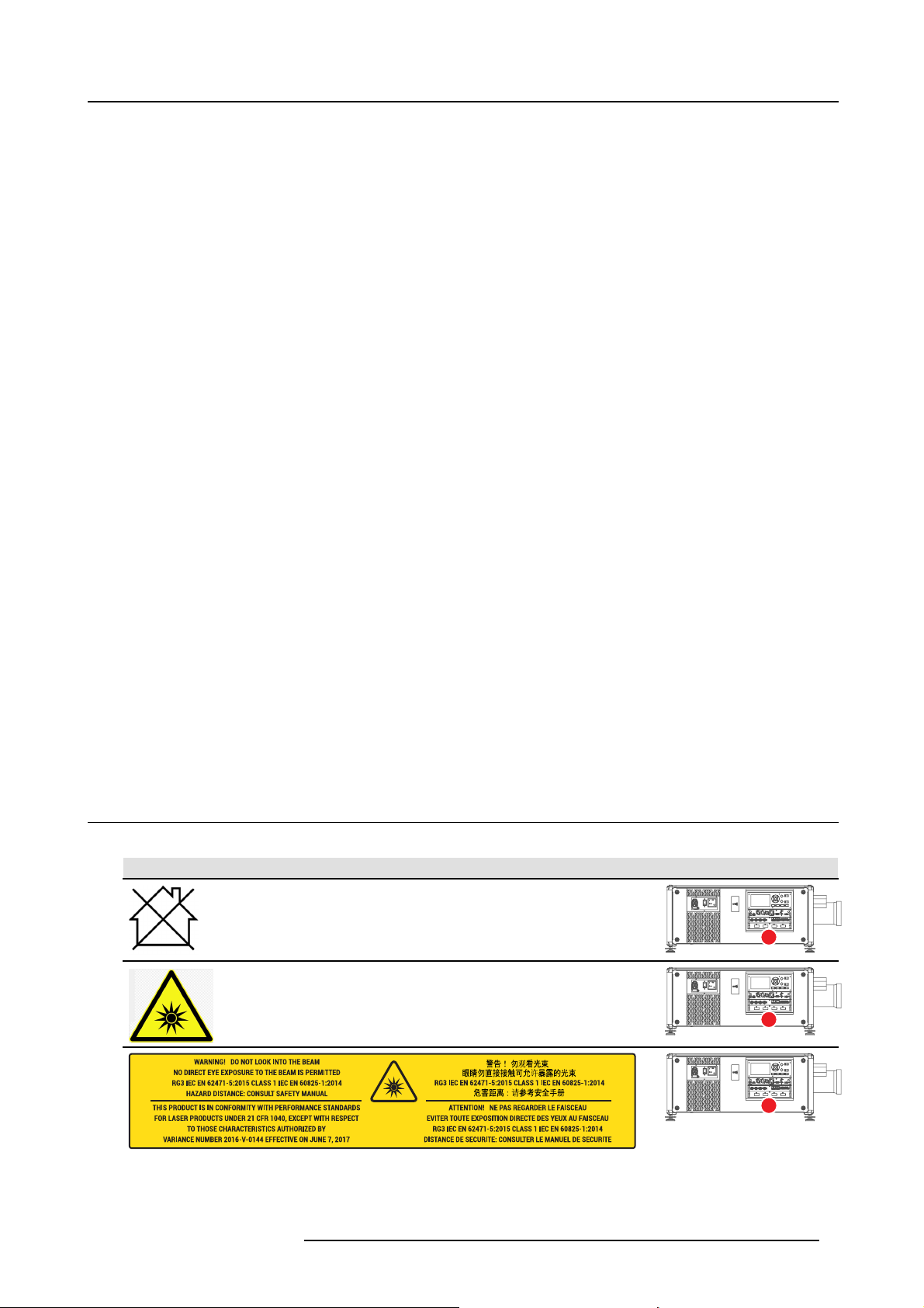
1.3 Product safety labels
Light beam related safety labels
Label im age Label description Label location
Hazard RG3: not for household use symbol.
Hazard RG 3: optical rad iation warning symbol.
WARNING! DO NOT LOOK INTO THE LIGHT BEAM NO DIRECT EYE EXPOSURE TO
THE BEAM IS PERMITTED. RG 3 IEC EN 62471–5:2015. CLASS 1 IEC EN 60825–1:2014.
HAZARD DISTANCE: CONSULT SAFETY MANUAL.
R5906112 UDX SERIES 17/06/2017 7
Page 12
1. Safety
Label im age Label description Label location
THIS PRODUCT IS IN CONFORMITY WITH PERFORMANCE S TANDARDS FOR
LASER PRODUCTS UNDER 21 CFR 1040, EXCEPT WITH RESPECT TO THOSE
CHARACTERISTICS A UT HORIZE D BY VARIANCE NUMBER 2016-V-0144 EFFECTIVE
ON JUNE 7, 2017.
警告! 勿观看光束 眼睛勿直接接触可允许暴露的光束 (RG3 IEC EN 62471-5:2015 CLASS 1
IEC EN 60825-1:2014) 危害距离:请参考 安全手册
DANGER ! NE PAS REGA RD ER LE FAISCEAU E VITER TOUTE EXPOSITION DIRECT E
DES YEU X AU FAISCEAU. RG3 IEC E N 62471-5:2015. CLASS 1 IEC EN 60825-1:2014.
DISTANCE DE SECURITE : CONS ULTER LE MANUEL DE SECURITE.
1.4 High Brightness precautions: Hazard Distance (HD)
HD
Hazard Distance (HD) is the distance mea sured from the projection lens at which the intensity or the energy per surface
unit becomes lower t han the applicable exposure limit on the cornea or on the skin. The light beam is considered (to
be) unsafe for exposure if the distance from a person to the light source is less than the HD.
Restriction Zone (RZ) based on the HD
The HD depends on the amount of lumens produced by the projector and the type of lens installed. See next chapter"HD in function
of modifying optics", page 11.
To protect untrained end us ers (as cinema visitors, spectators) the installation shall comply with the following installation requirements: Operators shall control access to the beam w ithin the hazard distance or ins tall the product at the height that will prevent
spectators’ eyes from being in the hazard distance. Radiation levels in excess of the limits will not be permitted at any point less than
2.0 meter (SH) above any su rface upon which persons other than operators, performers, or employees are permitted to stand or less
than 1.0 meter (SH) lateral separation from any place where su ch persons are permitted to be. In environments where unrestrained
behavior is reasonably foreseeable, the minimum separation height should be greater than or equal to 3 .0 meter to prevent potential
exposure, for example by an individual sitting on another individual’s shoulders, within the HD.
These values are minimum values and are based on the guidance provided in IEC 62471-5:2015 section 6.6.5.
The installer must understand the risk and apply protective mea sures b ased upon the hazard distance as indicated on the label and
in the user information. Installation method, separation height, barriers, detection system or other applicable control measure shall
prevent hazardous eye access to the radiation w
For ex ample, projectors that have a HD grea ter than 1 m and em it light into an uncontrolled area where persons may be present
should be positioned in accordance w ith “the fixed projector installation” parameters, resulting in a HD that does not extend into
the audience area unless the beam is at least 2.0 meter above the fl oor level. In environments where unrestrained beha vior is
reasonably foreseeable, the minimum separation height should be greater than or equal to 3.0 meter to prevent potential exposure,
for example by an individual sitting on another individual’s s houlders, within the HD. Sufficiently large separation height may be
achieved by mounting the image projector on t he ceiling or through the use of physical barriers.
For LIPs (Laser Illuminated Projectors) installed in the USA market the above limits do not apply. Lip’s for installations o ther than in
cinema theaters shall be installed at a height vertically above the floor such that the b ottom plane of the Hazard Zone shall be no
lower than 3 meters above the floor. Horizontal clearance to the hazard zone shall be 2.5 meters. Any human access horizontally
to the Hazard Zone, if applicable, shall be restricted by barriers. If human access is possible in an unsupervised environment, the
horizontal or vertical clearances shall be increased to prevent exposure to the RG3 hazard zone.
In addition for temporary installations (e.g.: rental and s taging, lease, ev ents …) the following requirements apply:
ithin the hazard distance.
• This product can only be ins talled by Barco or sold or leased only to valid laser light show variance holders. In other words
our installers are required to have an approved lase r light show variance. Suc h installers may currently hold a valid variance
for production of Class IIIb and IV laser light shows and/or for incorporation of the RG 3 LIPs into their shows. D ealers and
distributors are also required to obtain a valid laser light s how variance.
• This product shall be located in such a way that all propagating beam paths within the Restriction Zone, and the audience can
be directly observed at all times.
• Effects other than front or rear screen projections shall not be performed.
• Communication shall be maint
• In the event of any unsafe condition, imm ediately terminates (or designate the termination) of LIP projection light.
Install one or more readily accessible controls to immediately terminate LIP projection light. The power input at the projector side
is considered as a reliable disconnect device. W hen required to switch o ff the projector, disconnect the power cord at the projector
side. In case the power input at the projector side is not accessible (e.g. truss mount), the socket outlet supplying the projector shall
be installed nearby the projector and be easily accessible, or a readily accessible general disconnect dev ice shall be inco rporated
in the fixed wiring.
Laser light shows can be requested via the FDA online eSubm itter portal or via FDA Form FDA Form 3147 referencing to Barco’s
variance approval 2016 -V-0144.
8
ained with other personnel assisting in surveillance of the LIP projection.
R5906112 UDX SERIES 17/06/2017
Page 13
1. Safety
RA TH
HD
RA
SH
RZ
SH
Image 1-1
ASideview.
B Top view.
RA Restricted Access location (boot area of projector).
PR Projector.
TH Theater.
RZ Restriction Zone in the theater.
SH Separation Height.
SW S eparation Width.
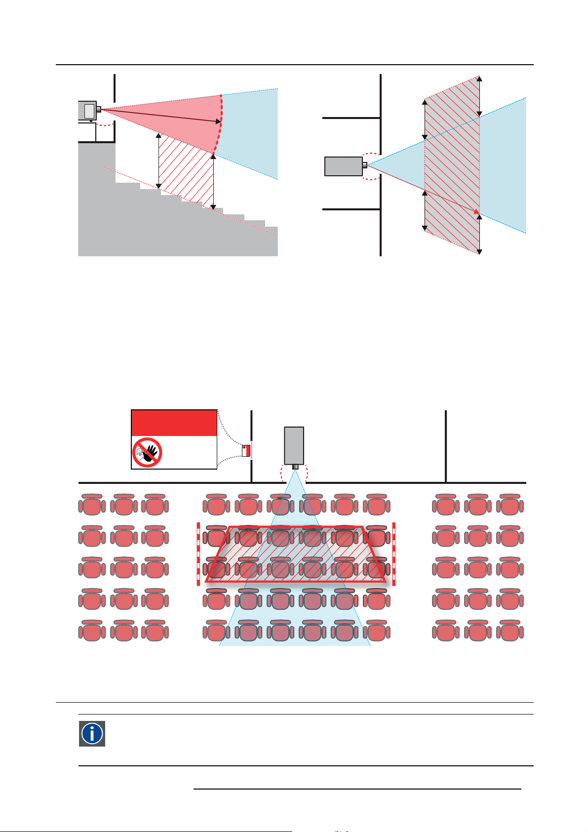
Based on national requirements, no person is allowed to enter the projected beam within the zone between the projection lens and
the related hazard distance (HD). This shall b e ph
The minim um separation height takes into account the surface upon w hich persons other than operator, performers or employees
are permitted to stand.
On image 1-2 a typical setup is displayed. It must be verified if these minimum requirements are met. If required a restricted zone
(RZ) in the theater mus t be established. This can be do ne by u sing physical barrier, like a red rope as illustrated in image 1-2.
The restricted area sticker can be replaced by a sticker w ith only the symbol.
ysically impossible by creating sufficient separation height or by placing barriers.
PR
(B) TOP VIEW(A) SIDE VIEW
TH
HD
SW
SW
SW
RZ
1m
SW
RESTRICTED
AREA
Image 1-2
1.5 HD for fully en
PR
RESTRICTED
AREA
closed projection systems
HD
Hazard Distance (HD) is the distance mea sured from the projection lens at which the intensity or the energy per surface
unit becomes lower t han the applicable exposure limit on the cornea or on the skin. The light beam is considered (to
be) unsafe for exposure if the distance from a person to the light source is less than the HD.
R5906112 UDX SERIES 17/06/2017 9
Page 14

1. Safety
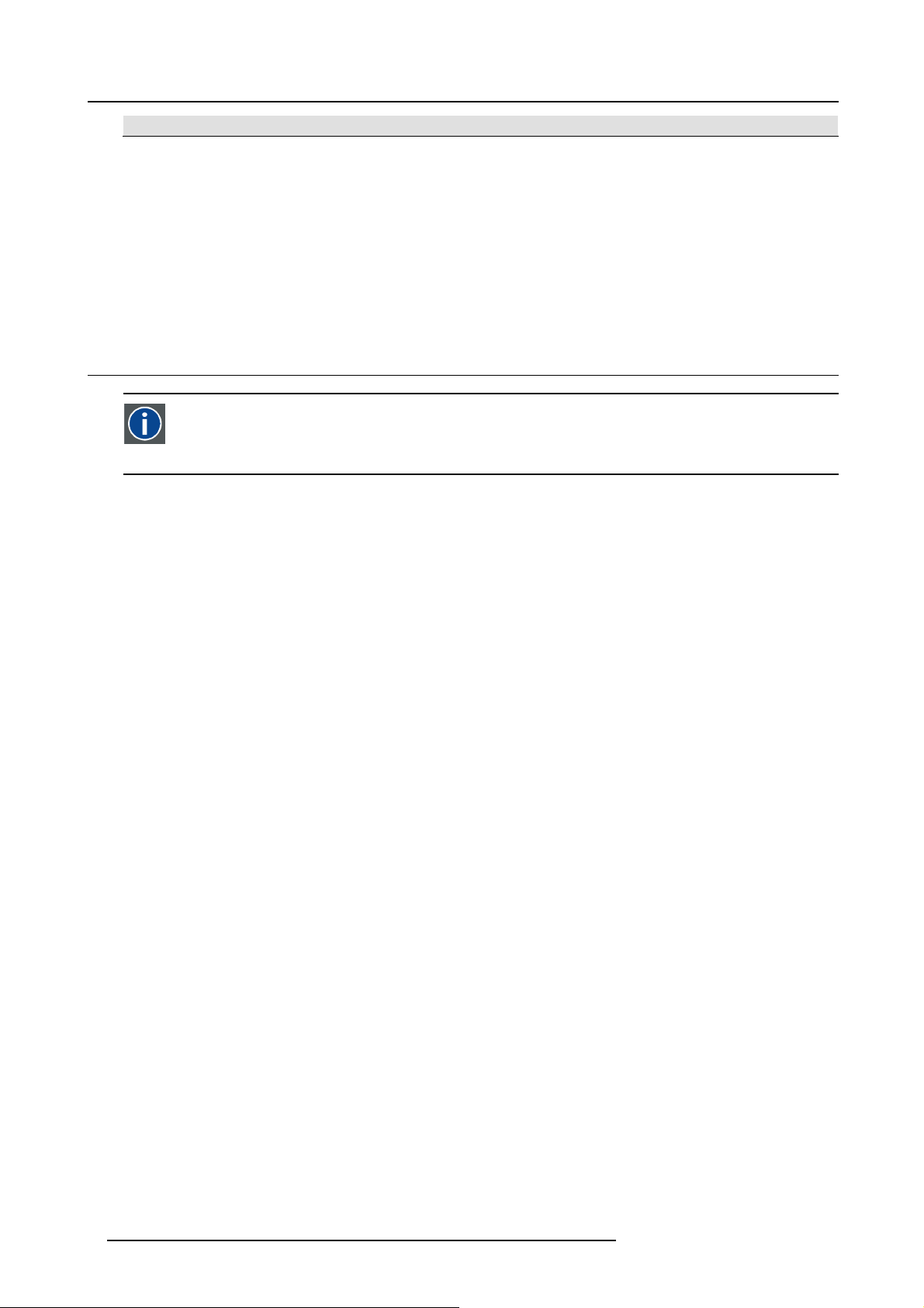
Restriction Zone (RZ) based on the HD
The projector is also suitable for rear projection applications; projecting a beam onto a defuse co ated projection screen. As displayed
in image 1-3 two areas should be considered: the restricted enclosed projection area (RA) and the observation area (TH).
RESTRICTED
RA TH
sw
AREA
RESTRICTED
AREA
HDDIFFUSE
RZ
sw
sw
PD
HD
REFLECTION
reflection
); also taking into account a 1 meter lateral
PR
sw
Image 1-3
RA Restricted Access location (enclosed projection area).
PR Projector.
TH Theater (observation area).
RZ Restriction Zone.
PD Projection Distance.
SW Separation Width. M ust be m inimum 1 meter.
For this type of setup 3 different HD shall be considered:
• HD as discussed in "High Brightness precautions: Hazard Distance (HD)", page 8 , relevant for intrabeam exposure.
•HD
•HD
: the distance that has to be k ept restrictive related to the reflected light from the rear projection screen.
reflection
: the relevant distance to be considered while observing the defuse surface of the rear projection screen.
diffuse
As described in "High Brightness precautions: Hazard Distance (HD)", page 8 , it is mandatory to create a restricted zone within
the beam areas closer than any NOHD. In the enclosed p
rojection area the combination of two restricted zones are relevant: The
restricted zone of the projected beam toward the screen; taking into account 1 meter Separation Width (SW) from the beam onward.
Combined with the restricted zon e related to the rear reflection from the screen (HD
separation.
The HD
projection screen. To determine the HD distance for the used lens and projector model see graphs in chapter "HD in function of
distance equals 25% of the difference between the determined HD distance a nd the projection distance to the rear
reflection
modifying optics", page 11.
HD
reflection
= 25% (HD – PD)
The light emitted from the screen within the observation shall never exceed the RG2 exposure limit, determined at 10 cm. The
HD
can be neglected if the measured light at the screen surface is below 5000 cd/m² or 15000 LUX.
diffuse
10 R5906112 UDX SERIES 17/06/2017
Page 15
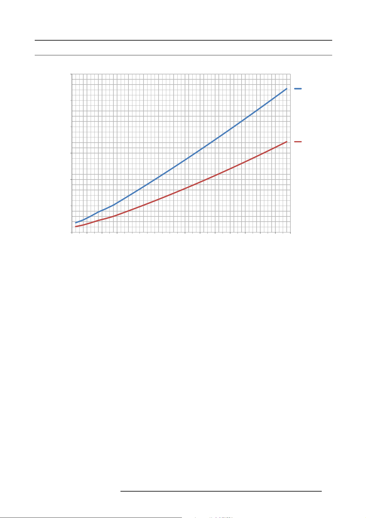
1.6 HD in function of modifying optics
Hazard Distance
12,00
10,00
8,00
6,00
Hazard Distance [m]
4,00
2,00
1. Safety
UDX 4K32
UDX U32
UDX W32
UDX 4K22
UDX W22
0,00
Image 1-4
0,5
0,9
1,3
1,7
2,0
2,3
2,7
3,1
3,5
3,9
4,3
4,7
5,1
Throw Ratio
5,5
5,9
6,3
6,7
7,1
7,5
7,9
8,3
8,7
9,1
9,5
9,9
10,3
10,7
11,1
11,5
R5906112 UDX SERIES 17/06/2017 11
Page 16

1. Safety
12 R5906112 UDX SERIES 17/06/2017
Page 17
2. Remote Control Unit
2. REMOTE CONTROL UNIT
2.1 Remote control, Battery installation
Where to find the batteries for the remote control ?
The batteries are not placed in the remote control unit to avoid control operation in its pac kage, r
time. At delivery the batteries can be found in a separated bag attached to the remote control unit. Before using your remote control,
install the batteries fi rst.
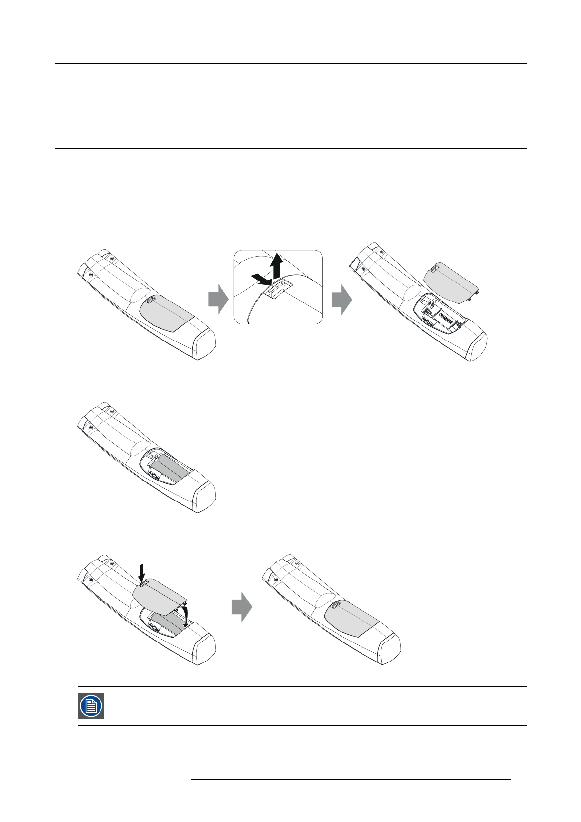
How to install
1. Push the battery cover tab with the fingernail a little back wards (1) and pull, at the same time, the cover upwards (2).
esulting in a shorter battery life
1
Image 2-1
2. Insert the two AA s ize batteries, making sure the polarities match the + and - marks inside the battery compartment.
Tip: Use alkaline batteries for optimum range and life time.
+
-
-
+
Image 2-2
3. Insert (1) both lower tabs of the battery cover in the gaps at the bottom of the re mote control, and press (2) the cover until it clicks
in place.
2
2
+
-
Image 2-3
When replacing batteries, the broadcast address of the RCU will b e reset t o its default value ’0’.
R5906112 UDX SERIES 17/06/2017 13
1
-
+
Page 18
2. Remote Control Unit
CAUTION: Replace with the correct battery type. Use two AA size batteries. There is a risk of explosion if the
battery is replaced w ith an incorrect type.
CAUTION: Replace the battery as explained above. There is a risk of explosion if t he battery is incorrectly
installed.
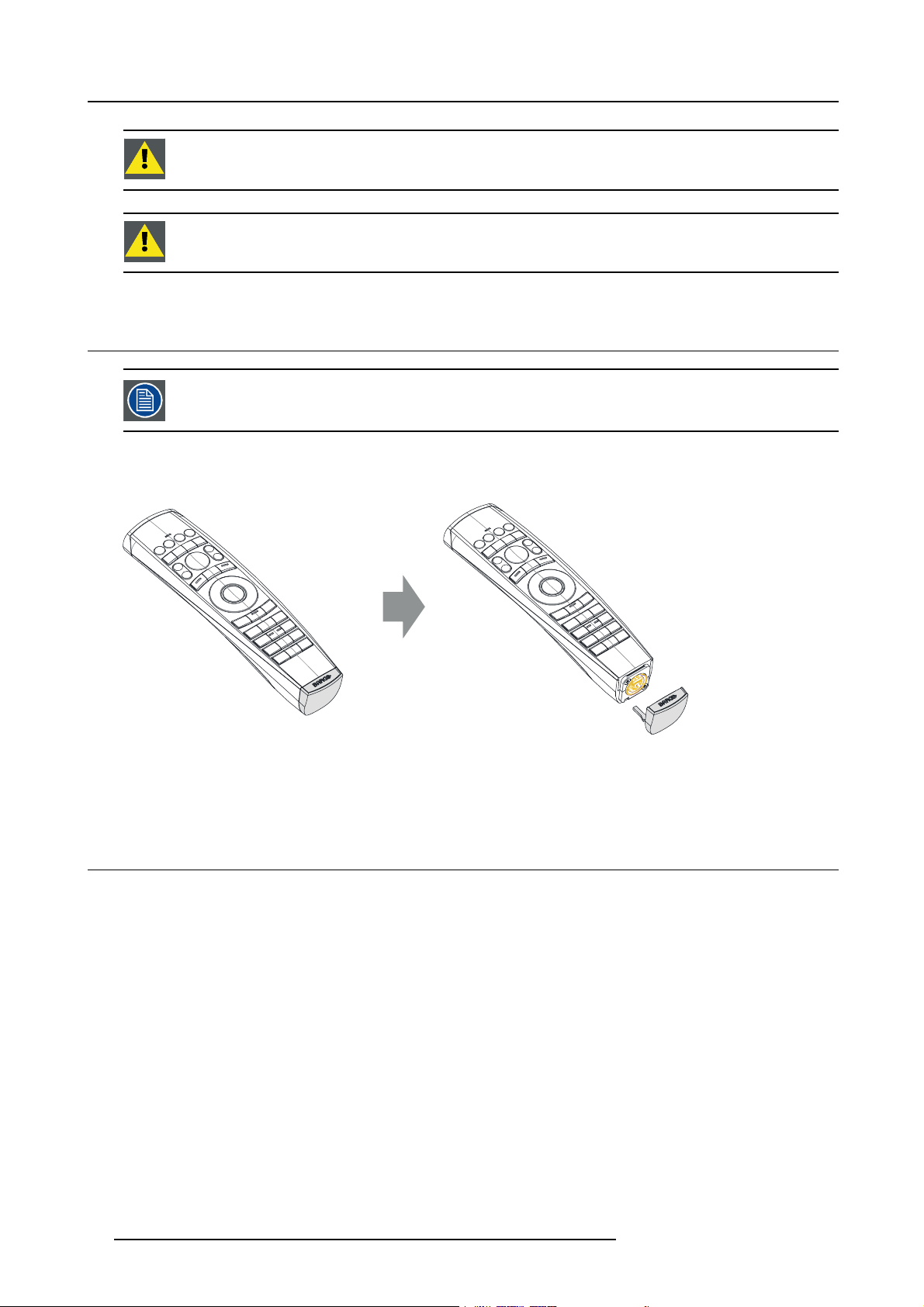
2.2 Using the XLR connector of the RCU
Connecting a cable with the XLR connector will reset the broadcast address of the RCU t o its default value ’0’.
How to use the XLR connector
1. R emov e the XLR cover by pulling it backwards.
Image 2-4
2. C onnect a cable with XLR plug into the XLR connector of the R CU.
3. C onnect the other end of the cable with the XLR inpu
t of the projector.
2.3 Remote control, on/off button
Purpose of the remote control on/off button
The Pulse remote control unit has at the front side an on/off switch (reference 1 image 2-5). Switching off the remote control prevents
that unwanted commands are send due to an accidental key press. F urthermore, switching the RCU off w ill extend the battery life
time of the remote control.
To activate the remote control press the on/off button.
To deactivate the r emote control press the on/off button again.
Default w hen (re)placing batteries, is “ON”.
14
R5906112 UDX SERIES 17/06/2017
Page 19

Image 2-5
2. Remote Control Unit
1
R5906112 UDX SERIES 17/06/2017 15
Page 20

2. Remote Control Unit
16 R5906112 UDX SERIES 17/06/2017
Page 21
3. Input & Communication
3. INPUT & COMMUNICATION
3.1 Introduction
General
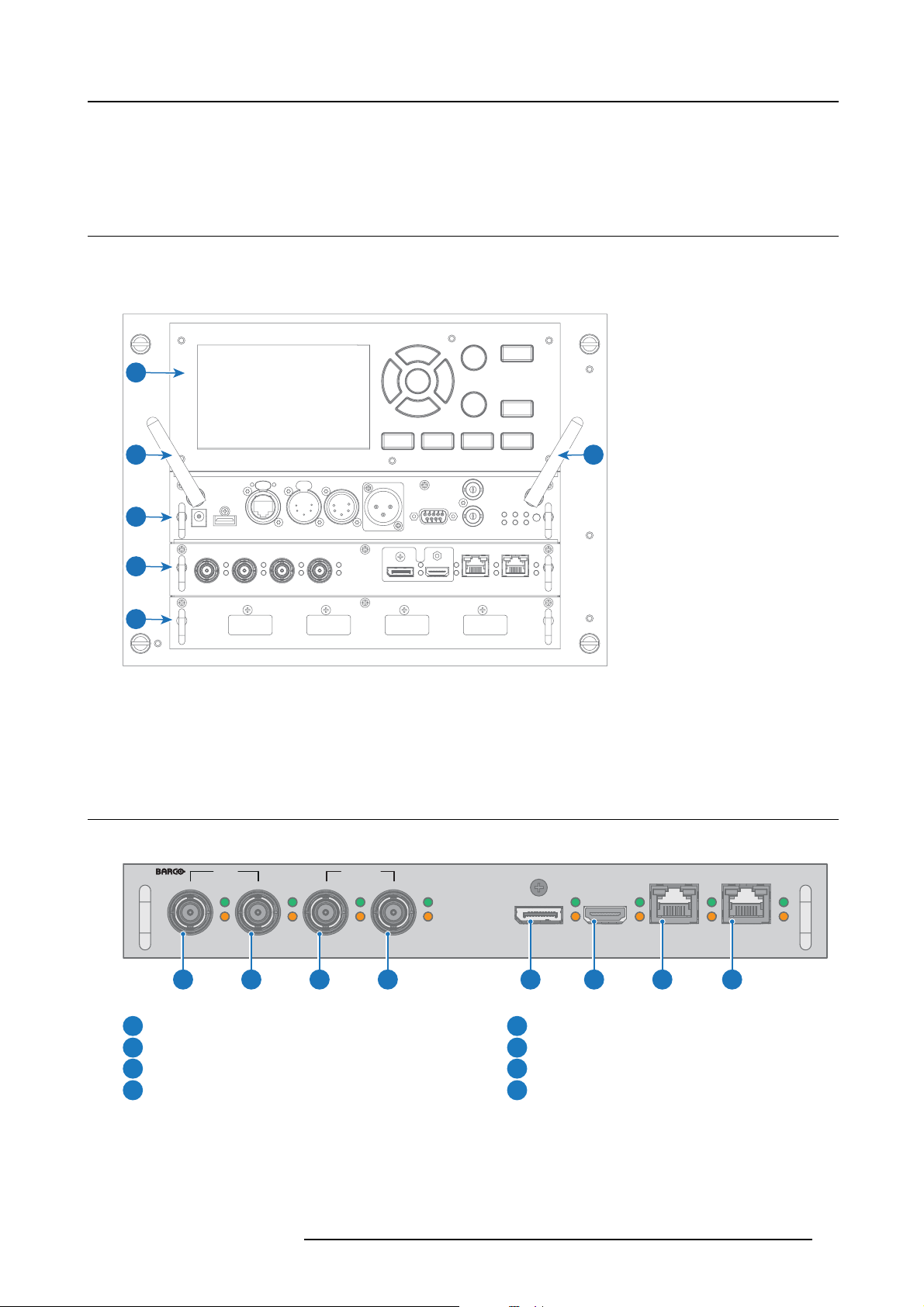
The Input & Co mm unication side of the projector consists of a local keypad, a communication panel, a
(V&H) and a free input slots. The free input slot can be used for optional modules (e.g. Virtual & Augmented Reality Input (V&AR)).
1
2 3
4
venues & hospitality Input
5
6
Image 3-1
1 Local Keypad and touch panel
2 Optional antenna for WiFi connection
3 Optional antenna for GSM
4 Communication Panel
5 Venues & Hospitality Input (V&H)
6 Free input slot (here filled wit h the V&AR modu le)
3.2 Input source connections – Venue & Hospitality Input (V&H)
Overview Venues & Hospitality Input (V&H)
SDI IN SDI IN/OUT
SEL
DP
SYNC SYNC
SEL
HDM I
Image 3-2
SEL
SYNC
A
SEL
SYNC
B
SEL
SYNC
C
SEL
SYNC
D
1 2 3 4 5 6 7 8
HDBT 1
SEL
SYNC
HDBT 2
SEL
SYNC
Quad 3G S DI channel A Input
1
Quad 3G S DI channel B Input
2
Quad 3G S DI channel C Input
3
Quad 3G S DI channel D Input
4
The yellow LED lights up whe n valid input sync is detected.
The green LED ligh
ts u p when the input is selected.
R5906112 UDX SERIES 17/06/2017
DisplayPort Input
5
HDMI Input
6
HDBaseT Input 1
7
HDBaseT Input 2
8
17
Page 22

3. Input & Communication
Input specifications – SDI Inputs
3G SDI follows the SM PTE 425M standard Level A
HD-SDI follows the SMP TE 292M sta ndard
Color space YCbCr
Color depth
Chroma sampling 4:2:2
Audio support not supported
For future release
Video timings Progressive
10 bpc
• 3D support
• Interlaced support
• Segmented frame support
• 12G S DI support
Type Port type Format
HD-SDI Single link Up to 1920 x 1080 @24 Hz
3G-SDI Level A Single link Up to 2048 x 1080 @ 50 Hz
3G-SDI “BarcoLink” Single link 1920 x 1200 @50 Hz, @59.94 Hz and
Up to 1920 x 1080 @25 Hz
Up to 1920 x 1080 @30 Hz
Up to 1280 x 7 20 @50 Hz
Up to 1280 x 720 @60 Hzz
Up to 2048 x 1080 @60 Hz
@60 Hz.
Input specifications – HDMI Input
Pixel rate 25 – 600 MHz pixel clock
HDCP s upport
Color Space
Color depth
Audio not supported
Video timings
• HDCP 1.x
• HDCP 2.2
• YCbCr 4:2:0
• YCbCr 4:2:2
• YCbCr 4:4:4
• 24 bpp
• 30 bpp
• 36 bpp
For future release
• 3D support
• Interlaced support
Up to 4096 x 2160 @24 Hz
Up to 4096 x 2160 @25 Hz
Up to 4096 x 2160 @30 Hz
Up to 2048 x 1080 @48 Hz
Up to 4096 x 2160 @50 Hz
Up to 4096 x 2160 @60 Hz
18
R5906112 UDX SERIES 17/06/2017
Page 23

CAUTION: The HDBaseT inputs can bridge a d istance of 100 m but is sensitive to radiated electromagnetic
interference: radiated electromagnetic interference ( e.g. from GSM or switching inductive o r capacitive loads)
within the limits of electromagnetic co mpatibility requirements of 3 V/m ca n cause random flashes or temporary loss of the projected image.
As such, shielded CAT-6 cables with metal RJ-45 connectors are recommended; choose cable length no longer
than required and route HDBT cable optimally screened from possible sources of electromagnetic emission.
Input specifications – HDBase-T inputs
Pixel rate 25 – 297 MHz pixel clock
Color Space
• YCbCr 4:2:2
• YCbCr 4:4:4
Color depth
• 24 bpp
• 30 bpp
• 36 bpp
For future release
• 3D support
• Interlaced support
•HDCP1.4
Audio not supported
Video timings Progressive
Up to 4096 x 21 60 @ 24 H z
Up to 4096 x 24 60 @ 25 H z
Up to 4096 x 24 60 @ 30 H z
Up to 2048 x 10 80 @ 48 H z
Up to 2560 x 16 00 @ 50 H z
Up to 2560 x 16 00 @ 60 H z
3. Input & Communication
CAUTION: In order to display high resolution im ages (ex.: 3840X2160@60Hz) via the DP1.2 input, the quality
of the cable must be adequate, in ad dition the length of the cab le can also influence the performance. In case
thereisanissuewithoneofthesecriteriatheau
to switch to a lower resolution.
Input specifications – DisplayPort 1.2 input
Pixel
rate
Color
Space
Color
depth
Datarate
Support
Audio not supported
3D
support
Up to 600 MHz pixel clock
• YCbCr 4:2:2
• YCbCr 4:4:4
• 24 bpp
• 30 bpp
• 36 bpp
• 1.62 G bps : Reduced Bit Rate (RBR)
• 2.7 Gbps: High Bit R at e (H BR )
• 5.4 G bps: High Bit Rate 2 (HB R2)
For future release:
• Passive 3D support
• Interlaced support
•HDCP1.4
Field se quential 3D (active 3D)
tomatic link-training initia te d by th e DP-standard may decide
R5906112 UDX SERIES 17/06/2017
19
Page 24

3. Input & Communication
Video timings progressive:
2D / 3D
2D
2D 2 Column mode (2x1 layout)
2D
2D
Active 3D
Layout Mode
Standard layout (1x1 layout)
4 Quadrant mode (2x2 layout)
4 Column mode (4x1 layout)
Supported formats
• Up to 4096 x 2160 @24 Hz
• Up to 4096 x 2160 @30 Hz
• Up to 2048 x 1080 @48 Hz
• Up to 4096 x 2160 @50 Hz
• Up to 4096 x 2160 @60 Hz
• Up to 2048 x 1080 @120 Hz
• 1920 x 2160 @60 Hz
• 1920 x 2160 @120 Hz
• 1920 x 2400 @60 Hz
• 1920 x 1080 @120 Hz
• 1920 x 1200 @120 Hz
• 2048 x 1080 @120 Hz
• 960 x 2160 @120 Hz
• 960 x 2400 @120 Hz
• 1024 x 2160 @120 Hz
• 960 x 2160 @120 Hz
• 960 x 2400 @120 Hz
• 1024 x 2160 @120 Hz
• 1920 x 1080 @120 Hz
• 1920 x 1200 @120 Hz
• 1920 x 2160 @120 Hz
• 2048 x 1080 @120 Hz
3.3 Input source connections – Virtual & Augmented Reality Input (V&AR) (Optional)
Virtual & Augmented Reality Input (V&A R) (Optional)
DP A
SEL
SYNC
DP B
SEL
SYNC
1 2 3 4
Image 3-3
Quad DisplayPort channel A Input
1
Quad DisplayPort channel B Input
2
The yellow LED lights up whe n valid input sync is detected.
The green LED lights u p when the input is selected.
Input specifications – DisplayPort 1.2 inputs
Pixel
rate
Color
Space
Up to 600 MHz pixel clock
• YCbCr 4:2:2
• YCbCr 4:4:4
Quad DisplayPort channel C Input
3
Quad DisplayPort channel D Input
4
DP C
SEL
SYNC
DP D
SEL
SYNC
20
R5906112 UDX SERIES 17/06/2017
Page 25

3. Input & Communication
Color
depth
Datarate
Support
Audio not supported
3D
support
Video timings progressive:
• 24 bpp
• 30 bpp
• 36 bpp
• 1.62 G bps : Reduced Bit Rate (RBR)
• 2.7 Gbps: High Bit R at e (H BR )
• 5.4 G bps: High Bit Rate 2 (HB R2)
For future release:
• Passive 3D support
• Interlaced support
•HDCP1.4
Field se quential 3D (active 3D)
2D / 3D
2D
2D 2 Column mode (2x1 layout)
2D
2D
Active 3D
Layout Mode
Standard layout (1x1 layout)
4 Quadrant mode (2x2 layout)
4 Column mode (4x1 layout)
Supported formats
• Up to 4096 x 2160 @24 Hz
• Up to 4096 x 2160 @30 Hz
• Up to 2048 x 1080 @48 Hz
• Up to 4096 x 2160 @50 Hz
• Up to 4096 x 2160 @60 Hz
• Up to 2048 x 1080 @120 Hz
• 1920 x 2160 @60 Hz
• 1920 x 2160 @120 Hz
• 1920 x 2400 @60 Hz
• 1920 x 1080 @120 Hz
• 1920 x 1200 @120 Hz
• 2048 x 1080 @120 Hz
• 960 x 2160 @120 Hz
• 960 x 2400 @120 Hz
• 1024 x 2160 @120 Hz
• 960 x 2160 @120 Hz
• 960 x 2400 @120 Hz
• 1024 x 2160 @120 Hz
• 1920 x 1080 @120 Hz
• 1920 x 1200 @120 Hz
• 1920 x 2160 @120 Hz
• 2048 x 1080 @120 Hz
R5906112 UDX SERIES 17/06/2017
21
Page 26
3. Input & Communication
3.4 Communication connections
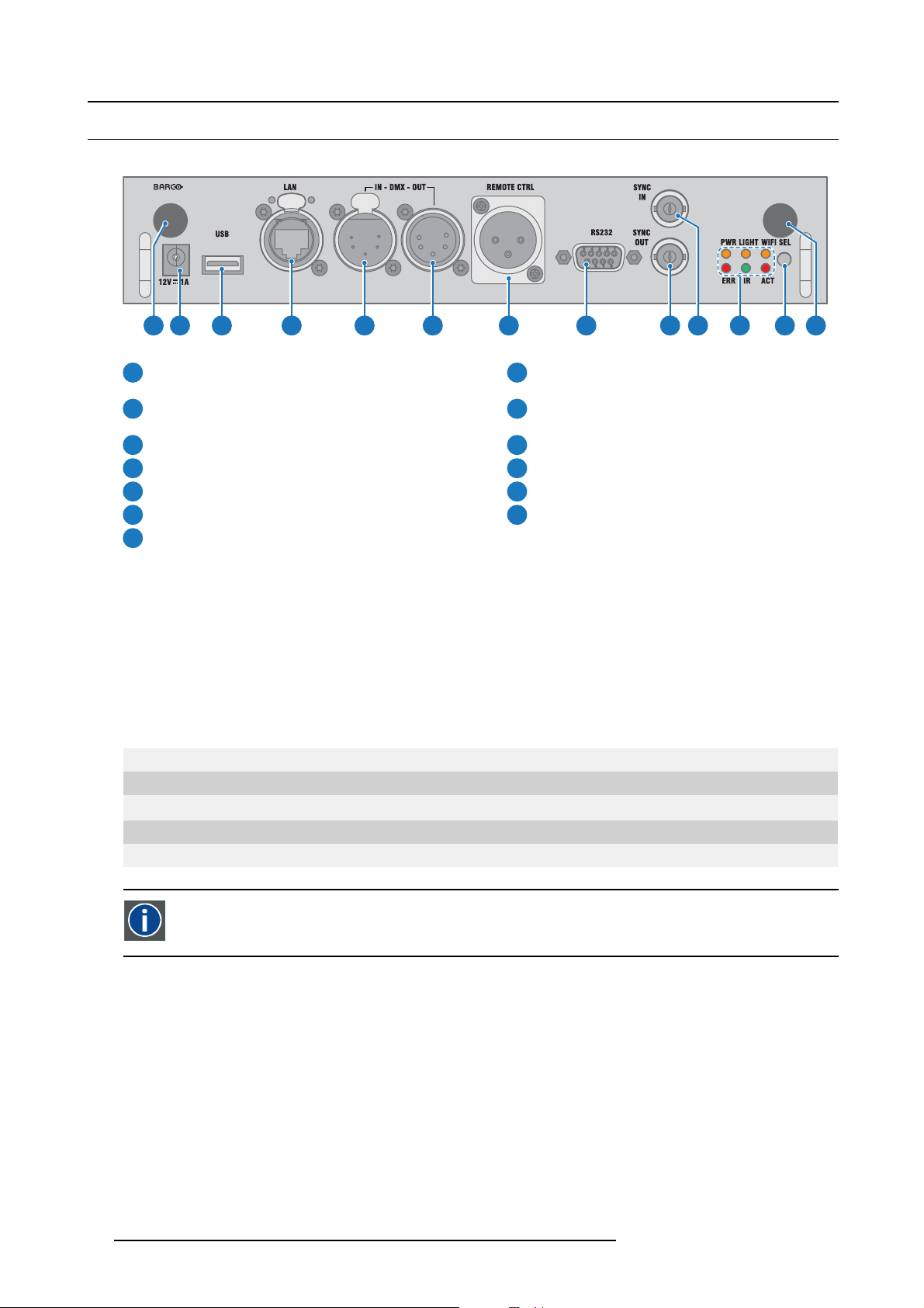
Communication Panel
321 4 5 6 7 8 9 10 11 12 13
Image 3-4
WIFI antenna for wireless IP (optional)
1
8
RS232 for serial communication
12V 1A output
2
Firmware update / USB backup custom settings
3
4
10/100 base-T for external control over IP and Art-Net
DMX interface input
5
DMX interface output
6
XLR input for wired pr ojector control
7
Sync Out 3D
9
Sync In 3D
10
Status lights
11
12
IR receive sensor
GSM antenna input (optional)
13
12V output
12 V output, maximum 1A, available when projector is not in stand by.
DMX interface
DMX is used as communication bus between different devices in the light technic. Each device has an input and an output, so that
the bus can be looped between the different dev ices. According the standard a five wire cable with X LR connector is used.
You can use the DMX input port to connect a DMX device (DMX console) to the projector. This way you can control the projector
from that DMX device (console). The DMX output port can be connected with the next d evice in the loop.
Pin Description
1Earth
2Cold
3Hot
4 Return - (or not used)
5
Return + (or not used)
DMX
DMX-512 Lighting protocol over RS-485 interface. Carries information of 512 channels from a lighting controller to
lighting devices. Standardized by U S ITT.
RS232/RS422 input
The communication interface of the UDX supports RS232 and RS422 serial comm unication on two different types of input connectors, a Sub-D connector and an USB connector acting as RS input when connected to an USB input of a PC.
You can use the RS232/RS422 input to connect a local PC to your UDX. By this way you can configure and control your UDX from
your local PC.
Advantages of using RS 232/RS422 serial communication:
• easy adjustment of the projector via PC (or MAC).
• allow storage of multiple projector configurations and set ups.
• wide range of control possibilities.
• address range from 0 to 255.
• sending data to the projector ( update).
• copying data from the projector (bac kup).
22
R5906112 UDX SERIES 17/06/2017
Page 27
Pin Description
1 DCD : Data Carrier Detect
2RXD-:ReceiveData
3 TXD- : Transmitted Data
4 DTR : Data Terminal Ready [RS232]
TXD+ : Transmitted Data [RS422]
5
GND : Ground
6 DSR : Data Set Ready [RS232]
RXD+ : Received Data [RS422]
7
— (not connected) —
8CTS:ClearToSend
9 RI : Ring Indicator
RS232
An Electronic Industries Association (EIA) serial digital interface standard specifying the characteristics of the com m unication path between two devices using either D-SUB 9 pins or D-SUB 25 pins connectors. Th is s tandard is used for
relatively short-range communications and does not specify balanced control lines. RS-232 is a serial control standard
with a set number of conductors, data rate, wor d length and type of connector to be used. The standard specifies component connection standards with regard to computer interface. It is also called RS-232-C, which is the third version
of the RS-232 standard, and is functionally identical to the CCITT V.24 standard. Logical ’0’ is > + 3V, Logical ’1’ is < 3V. The range between -3V and +3V is the transition zone.
3. Input & Communication
RS232/422 input (Sub-D) port
RS422
An EIA serial digital interface standard that specifies the electrical characteristics of balanced (differential) v oltage,
digital interface circuits. This standard is usable over longer dist
chronous transmission of computer data at speeds of up to 920,000 bits per second. It is also used as the serial port
standard for Macintosh computers. When the difference between the 2 lines is < - 0.2V that equals with a logical ’0’.
When the difference is > +0.2V that equals to a logica
l’1’..
ances than RS-232. T his signal governs the asyn-
USB port
The communication interface is equipped with a mast
cedures for software updates or for taking backup files from the projector without network connection. An USB-stick is plugged into
the USB port and files can be transferred from or to the projector using the local or remote control unit. Note that the USB-stick has
to be Linux FAT16 com patible.
er USB port, type “A” connector. This USB port will simplify the service pro-
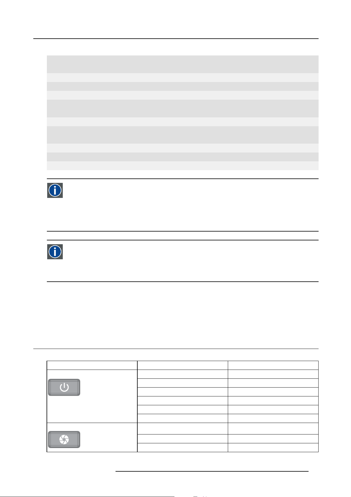
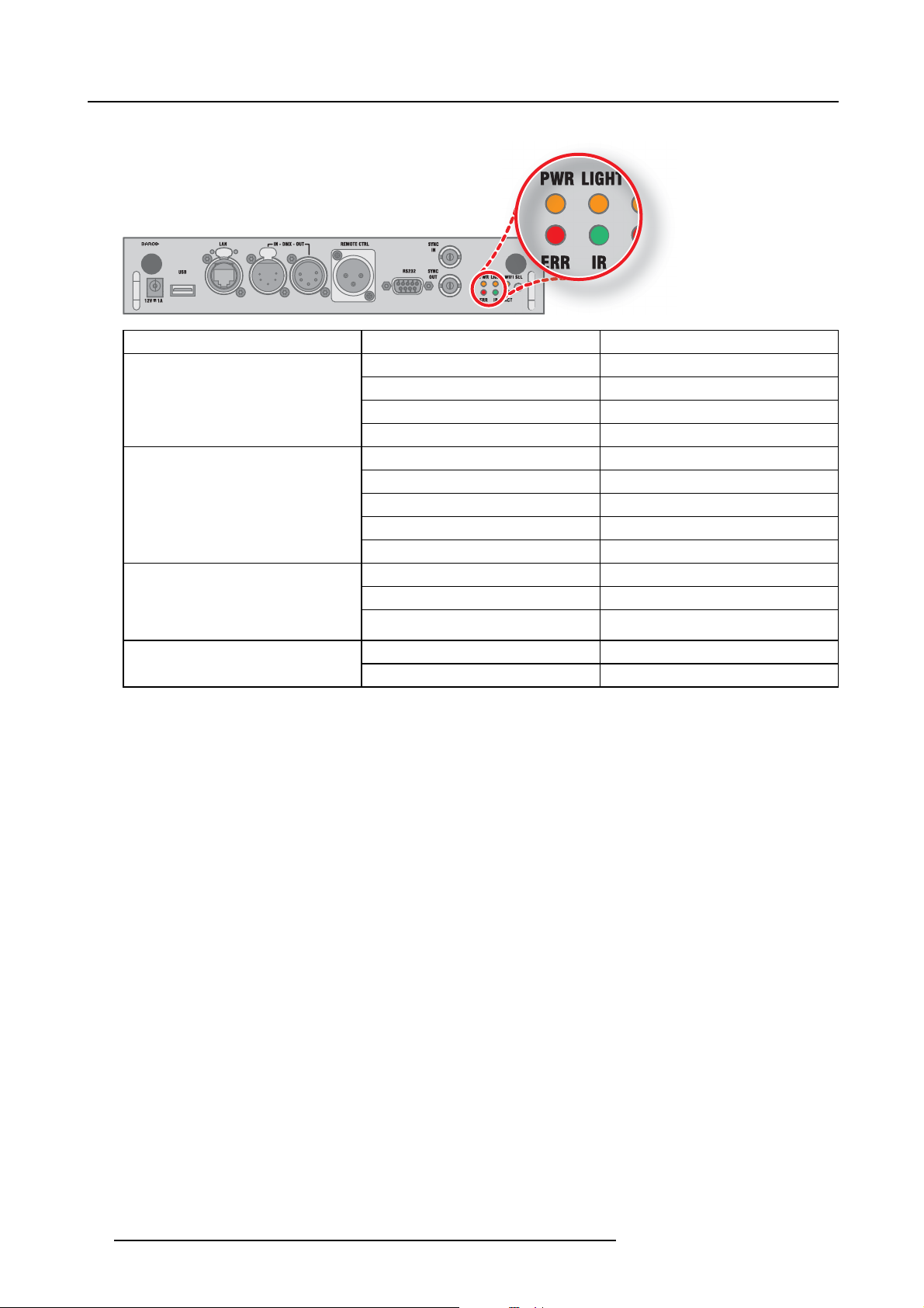
3.5 LED and Button indication chart
Button Backlight Status
Button Color status Description
Standby button
Shutter button
Blinking W HITE (slow) Projector starts up (booting)
Blinking W HITE (fast) Firmware upgrade
Solid W H ITE Projector is in Standby mode
Blinking B LUE Projector goes to ON mode
Solid BLUE Projector is O N
Blinking RED Error condition
Off (no color) P rojector is OFF, starts up, or is in Standby
mode.
Solid W H ITE Projector is ON, shutter is open
Solid RED Projector is ON, shutter is closed
R5906112 UDX SERIES 17/06/2017 23
Page 28
3. Input & Communication
LED Status
LED Color st atus Description
PWR (power LE D)
LIGHT (Illumination LED)
ERR (error LED)
Off Projector powers up
RED Projector is in Standby
ORANGE Projector is Ready
GREEN Projector is on
Off Light source is off
RED No light source detected
ORANGE Light source is on in ECO mode
GREEN Light source is on in normal mode
GREEN-ORANGE Light source is on in CLO mode
Off No error
RED toggles on/off Error
ORANGE toggles on/off Warning
RED IR signal receivedIR
GREEN IR signal acknowledged
24 R5906112 UDX SERIES 17/06/2017
Page 29

4. Getting Started
4. GETTING STARTED
How controlling the projector ?
The projector can b e controlled by the local keypad, by the remote control unit or by browser application.
Location of the local keypad ?
The local keypad is located on the input side of the projector.
Remote control functions.
This remote control includes a battery powered infrared (IR) transmitter that allows the user to control the pr ojector remotely. T his
remote control is used for source selection, control, adaptation and set up.
Other functions of the remote control are :
• switching between stand by and operational mode.
• switching to "pause" (blanked picture, full power for immediate r estarting)
• direct access to all c onnected sources.
Overview
• Functionality o verview
• Power on projector
• Switching to standby
• Power off projector
• Using the RCU
• Projector Address
• Quick setup via Direct access
4.1 Functionality overview
Local Keypad ov erview
1
Menu S election.
2
Menu Activation, OK button
3
OSD On/Off.
4
Menu Back.
5
Power On/Off.
6
Touch Panel On/Off.
7
Input Selection.
8
Shutter Open/Close.
9
Test Patterns.
10
Lens Menu.
11
Touch Panel.
The Keypad gives direct access to several funct
The keypad has a back light that can be switched on and off manually. The light turns off automatically after a preselected time.
The keys are equipped with white and blue backlit LEDs. Power button is equipped with white, blue and red backlit. The LEDs are
controlled according to the features available.
ions, in addition to access to the menu system.
1 2 3 4 5 6
1011 9 8 7
R5906112 UDX SERIES 17/06/2017
25
Page 30

4. Getting Started
Remote Control Unit buttons
1
2
3
4
5
6
7
8
9
10
11
12
13
14
15
24
23
22
21
20
19
18
17
16
1
Button pressed indicator.
2
Shutter Op en.
3
Shutter C lose.
4
Touch Panel On/Off.
5
OSD On/Off.
6
Lens Zoom.
7
Lens Shift.
8
Menu A ctivation.
9
Menu Selection, OK button.
10
Menu Navigation.
11
Input Selection.
12
Address button.
Numeric buttons.
13
Backspace (while entering
14
values)
XLR c onnector.
15
Decimal mark (while entering
16
values)
Macro button.
17
Menu Back.
18
Default button.
19
Lens Focus.
20
Color On/Off.
21
Test Patterns.
22
Power On.
23
Power Off.
24
Stereo Jack.
25
RCU O n/Off.
26
2625
The projector remote control is a full featu re wireless remote control, powered by two (2) standard AA batteries. The battery compartment is on the back side of the remote control.
The remote control is backlit for use in dark environments. It also has an XLR connector for wired connection to the projector. When
the wire is connec ted, the IR beam is switched off.
LCD panel
The LCD panel has two main functions:
1. Showing the menus and adjustment information. and also a mirror of the OSD, (On Screen Display) described in User Interface
when this is enabled.
2. Information regarding the status of the projector showing this data:
- Projector status
- Network address
- Active source
- Current firmware version
- Operation Data
- Active functions (Enabled Functions).
Toggle between the two indications by using the Menu button on the keypad, or on the remote control
The LCD Display will fade out 30 seconds after the last key operation.
4.2 Power on projector
How to power on
1. Pres s the mains switch at the side of the projector to switch on this projector.
26
R5906112 UDX SERIES 17/06/2017
Page 31

4. Getting Started
Image 4-1
Mains switch
- When ’0’ is pressed, the projector is switched off.
- When ’I’ is pressed, the projector is switched on.
The projector starts up to standby mode. The Power on/off button will blink until standby mode is achieved. Once in standby
mode, the Powe r on/off button will be lit WHITE, but the display will be off.
2. Pres s the Power on/off button on the projector, or the Power On button on the remote control.
The projector will continue to power on mode. T he Power on/off button will blink until the projector is ready. On c e the p rojector
is ready, the Power button will be lit BLUE.
The start up screen is displayed on the touch panel a nd when fully started up, it changes to the ov erview screen.
1
2
Image 4-2
The current mains input voltage is indicated on the voltmeter just above the power switch.
The background image of the startup screen and info screens can be changed with Projector Toolset with an
installed U DX plug-in.
Status overview
Once the projector is s tarted, press Status to get an overview of parame ters such as :
• Device serial number and article number
• Current firmware version and model name
• Current illumination (in percentage)
• Projector runtime in hours
• Uptime in hours
• Chosen source
• Current resolution and refresh rate
• Chosen communication method and IP address (if connected)
• Active functions
R5906112 UDX SERIES 17/06/2017
27
Page 32

4. Getting Started
Starting image projection
1. M ake sure the available sources are connected to the app ropriate input ports.
Tip: If properly c onnected, the “SYNC” LED will lit up ORANGE.
2. Pres s the Input Selection button on the keypad or on the remote control until:
- the LED of the selected s ource (the “SEL” LED) lit up G REE N, and
- the image of the selected source is projected.
1 2
Image 4-3
4.3 Switching to standby
How to s witch to standby
1. Pres s and hold the Power on/off button for 3 seconds on the local keypad, or press the Power Off button on the remote control.
The projector goes to standby mode. Th e after-cooling cycle will start (about 30 seconds). During this period the Power on/off
button will blink. Once the after-cooling cycle has ended, the projector will be in standby mode and the Power on/off button will
be lit WHITE .
3 s
30 s
Image 4-4
4.4 Power off projector
CAUTION: This procedure assumes the p rojector is in standby m ode.
How to power off
1. Sw itch off the projector with the mains switch. ’0’ must be pressed.
28
R5906112 UDX SERIES 17/06/2017
Page 33

Image 4-5
2. U nplug the power cord from the projector.
4.5 Using the RCU
Pointing to the reflective screen
1. Point the front of the RCU to the reflec tive screen surface.
4. Getting Started
Image 4-6
IR control via reflective screen
Hardwired to the XLR input
1. Plug one end of the remote cable in the connec tor on the bottom o f the RCU.
2. Plug the other end in the big connector on the communication interface of the projector, labelled Remote CTRL.
Note: Plugging the remote control will switch the broadcast address of the remote control to the d efault value ’0’. This is the
only broadcast address that will work when hardwired. If you want to change the broadc ast address after disconnecting
the remote control, see "Projector Address", page 30.
Pointing directly to the IR sensor
When using the wireless remote control, make sure you are within the effective operating distance (30 m, 100 ft in a straight line).
The remote control unit will not function properly if strong light strikes the sensor window or if there are obs tacles between the remote
control unit and the projector
R5906112 UDX SERIES 17/06/2017
IR sensor.
29
Page 34

4. Getting Started
45°
45°
Image 4-7
RCU to one of the IR sensors
45°
45°
45°
45°
Using the RCU in combination with a 3D emitter
When using a 3D emitter that radiates IR beams (e.g. the optional 3D emitter that Barco provides), the IR beams of the 3D emitter
may interfere with the IR communication between projector and the RCU.
If such interference occurs, connect the RCU to the projector us ing the remote cable with XLR connector. It is also be advised to
turn the IR receivers of the projector off to avoid the 3D emitter interference. The IR receivers can be turned off in the GUI: Sys tem
Settings” → “Communication” →“IR Control “.
4.6 Projector Address
Projector address
Address installed in the projector to be individually controlled.
Broadcast address
Projector will always execute the command coming from a RCU programmed with that broadcast address.
4.6.1 Controlling the projector
Why a projector address?
As more than one projector can be installed in a room, each projector should be separately add ressable with an RCU or computer.
Therefore eac h projector has its own address.
Set up an individual Projector Address
The set up of a projector address can be done via the software.
Projector controlling
Every projector requires an individual address between 0 and 255.
When the ad dress is set, the projector can be controlled now:
• with the RCU: only for addresses between 0 and 31.
• with a com puter: for any address between 0 and 255.
Broadcast Address
Every projector has a broadcast (comm on) address ’0’ or ’1’. The default address is ’0’.
The choice between ’0’ and ’1’ can be selected in the GUI: “System S ettings” → “Communication” →“IR Control “.
30
R5906112 UDX SERIES 17/06/2017
Page 35

Placing new batteries in the remote control or plugging the rem ote to a p rojector via XLR cable will automatically reset the address back to its default value ’0’.
4.6.2 Displaying and Programming addresses into the RCU
Displaying the Projector Address on the Screen.
1. Pres s the Address button to see the projector address (proximately 2 seconds).
The projector’s addres s is displayed on the LCD status screen.
How to Program an Address into the RCU?
1. Pres s the Address button until the B utton pressed indica tor lights up continuously (proximately 5 seconds).
2. En ter the addre ss with the digit buttons within the time the indicator lights up (also proximately 5 seconds).
Note: That address can be any value between 0 and 31.
Tip: A few examples:
To enter address 3, press "3" digit button on the RCU to set the RCU’s address to 3 and wait until the button pressed
indicator is out. Alternatively, you can also press “0” and “3”. This way, he button pressed indicator goes out immediately.
To enter address 31, then press “3” and “1” on the digit button on the RCU and the button pressed indicator goes out
immediately.
4. Getting Started
4.7 Quick setup via Direct access
Quick source selection
1. Pres s the Input button on the remote control or local keypad.
Image 4-8
I
I
R5906112 UDX SERIES 17/06/2017 31
Page 36

4. Getting Started
The source selection menu opens.
Image 4-9
Input selection
2. U se the arrow keys to select the desired source.
Quick test pattern selection
1. Pres s the Test pattern button on the remote control or local keypad.
P
P
Image 4-10
A first test pattern will be displayed.
2. Pres s as may times on that button until the desired pattern is displayed
32
R5906112 UDX SERIES 17/06/2017
Page 37

5. Graphic User Interface (GUI)
5. GRAPHIC USER INTERFACE (GUI)
Overview
•Overview
• Navigation
• Test Patterns
5.1 Overview
GUI - M ain Menu overview
The projector on screen display (OSD) is the primary user interface (UI). From here, you can review and adjust all projector and
display settings.
The OSD interface uses tabs to display the main menu. Each main menu contains submenus .
The OS D can be disabled by pressing the OSD on/off button.
Image 5-1
Home menu
The projector’s software platform uses access levels what each user can do. A standard user has access to all projector functionality.
Acertified service technician has also access to the service me nu. This menu is p asswor d protected.
5.2 Navigation
Navigation via the RCU or loc al keypad
Navigating the OSD can be done using the remote control or the local keypad.
1 4
2 3
3 2 1
4
Image 5-2
To start up the menu structure, press MENU (1).
R5906112 UDX SERIES 17/06/2017
33
Page 38

5. Graphic User Interface (GUI)
Use the arrow k eys (Me nu Navigatio n buttons) to navigate to the desired menu item (2). The background color changes to light
blue.
Press the Menu Selection button (center key of the arrow keys), also called OK button, to activate that item and to jump one level
deeper (3).
Use the numeral keys to enter values, or use the arrow keys to m ove the bar scale up or down.
Press the Back button to go up one level (4).
Image 5-3
Home menu
Remark: a blue slider bar on the right side of the window means that there are m ore items to show than those currently displayed.
Define values
Menu settings are displayed using check boxes, bar scale sliders, and drop-down lists.
To set a value:
•PressOK to select or deselect a checkbox (turn a function ON or OFF).
• Use the arrow keys to move the bar scale slider up or down on the value line. For a bar scale 0-9, each step will equal 10% of
the total value.
• To enter the value as a direct number, press OK, input the digit(s), and then press OK again to execute and exit cursor mode
e.g. OK 79 OK.
Within an input field, use the * button as back space button to remove an e
Changes to values are implemented dynamically.
To enter values with the local keyboard, use the arrow keys to select the first digit, press OK. Select the second digit and press OK.
Continue until all digits are entered. Close the action by selecting the enter (↵) button and press OK. Select the backspace button
and pr ess OK to remove the last entered digit.
ntered digit. Use the # button to enter a dot (.).
Menu memory
The OSD menu remembers the last selected sub-item as long as the projector is running. The menu memory is r eset when restarting
the projector from standby.
5.3 Test Patterns
How to use test patterns
1. In the m ain menu, select Test P atterns.
Or,
Push the Test Patterns button on the RC or on the local keypad.
Image 5-4
Main menu, Test Patterns
2. In the Test Patterns menu, select either Internal,orOutput test patterns.
3. In the chosen submenu, select the desired test pattern from the list.
You can select one of the following Internal test patterns:
34
R5906112 UDX SERIES 17/06/2017
Page 39

- Color bars
- Checker board
- Blue / Green / Red / White
- Convergence
-Focus
- Aspect
- Scheimpflug White / Green
- Cross hatch
- Monoscope
You can select one of the following Output test patterns:
- Vertical / diagonal lines
- Step bar
- Blemish zone
- Checkerboard
- Color bars
- Convergence
-FIP
- Full screen black / white / blue / green / red / cyan / magenta / yellow
-Grid
- Vertical Ramp
- Horizontal Ramp
-MTF
4. To turn the test pattern off, return to the previous m enu.
5. Graphic User Interface (GUI)
R5906112 UDX SERIES 17/06/2017
35
Page 40

5. Graphic User Interface (GUI)
36 R5906112 UDX SERIES 17/06/2017
Page 41

6. GUI – SOURCE
About the Source menu
This m enu is used to select, review an d configure sources into the p rojector.
Overview of features
• Source Selection
• Connector Settings
6.1 Source Selection
How to select?
1. Pres s Menu to activate the menus and select Source.
6. GUI – Source
Image 6-1
Select Source
2. Pres s OK.
The Select Sou rce menu is displayed with the actual available sources filled out.
Image 6-2
Input selection
3. S elect the desired input.
6.2 Connector Settings
How to configure the connector
1. Pres s Menu to activate the menus and select Source.
Image 6-3
Select Source
2. Pres s OK.
R5906112 UDX SERIES 17/06/2017
37
Page 42

6. GUI – Source
The Select Sou rce menu is displayed with the actual available sources filled out.
3. Scro ll down to the bottom of the list and select Connector Settings.
Image 6-4
The available sources are displayed.
Image 6-5
Select source
4. Se lect the desired c onnector.
The Connector Settings menu for this conne ctor will be displayed. All default values are Auto.
Image 6-6
5. To apply a limit on the used color space, select one of the other values in Color space.
6. To apply a limit on the used signal range, select one of the other ranges in Signal R ange.
38
R5906112 UDX SERIES 17/06/2017
Page 43

7. GUI – IMAGE
Overview of features
• Setting image levels manually
• P7 Realcolor
• Setting the output resolution
• HDR – Perceptual Quantizer (PQ)
7.1 Setting image levels manually
Purpose
Contrast: Change the contrast of the complete output signal (main and P iP window together) of the projected image.
Brightness: Change the brightness of the complete output signal (main and PiP window together) of the projected im age.
Saturation: Change the saturation of the complete output signal (main and PiP window together) of the projec
How to set up Contrast
1. In the main menu, select Image → Contrast.
7. GUI – Image
ted image.
Image 7-1
Image menu — Contrast
2. U se the ◄ or ► key to change the contrast enhancement until the desired valu
Image 7-2
Contrast slider
3. U se the ▲ or ▼ key to select Saturation or Brightness.
Or,
go to Home - Image and select Saturation or Brightness.
How to set up Brightness Level
1. In the main menu, select Image → Brightness.
e is re ached (adjustable between 0 and 2).
R5906112 UDX SERIES 17/06/2017
39
Page 44

7. GUI – Image
Image 7-3
Image menu — Brightness
2. U se the ◄ or ► key to change the brightness until the desired value is reached (adjustable between –1 and 1 ).
Image 7-4
Brightness slider
3. U se the ▲ or ▼ key to select Contrast or Saturation.
Or,
go to Home - Image and select Contrast or Saturation.
How to set up Saturation Level
1. In the main menu, select Image → Saturation.
Image 7-5
Image menu — Saturation
2. U se the ◄ or ► key to change the saturation until the desired value is reached (adjustable between -1 and 1).
Image 7-6
Saturation slider
3. U se the ▲ or ▼ key to select Brightness or Contrast.
Or,
go to Home - Image and select Brightness or Contrast.
40
R5906112 UDX SERIES 17/06/2017
Page 45

7. GUI – Image
7.2 P7 R ealcolor
Purpose
When blending images from multiple projectors, the measured color coordination of each projector can be altered to a desired
common lev el. T his so that the projected colors are identical over all projectors used.
How to set the P7 desired values
1. In the main menu, select Image → Advanced → P7 Realcolor.
Image 7-7
Advanced menu — P7 Realcolor
The P7 menu is d isplayed.
Image 7-8
P7 Realcolor menu
2. S elect the desired Mode. Choose one of the following:
- Native: Default mode, with default values. All other options in the P7 menu are disabled.
- Custom RGB: 3–point color configuration. In RGB mode, the C , M and Y coordinates will be calculated automatically based
on the R, G and B coordinates.
- Custom RGBCMY: 6–point color configuration (bo th RGB and CMY). In RGBCMY mode, ea ch color can be given a specific
coordinate within the m easured color triangle.
- Custom WHITE:Configure only the W hite temperature.
3. D efine the coordinates for each available color.
Click on a coordinate value and select the current value. Enter the d esired value with the numeric keys.
Note: You can only pick c oordinates within the measured color triangle.
4. For Custom White, click on White point and choose one
- Coordinates:Configure the white point via specific coordinates. The white point is specified using an x, y coordinate in the
CIE 1931 Chart.
- Temperature:Configure the white point via a color temperature slider. The white point is specified on a Kelvin scale between
3200K and 13000K tracking along the black body curve.
You can reset all coordinates to the default values (to native) by selecting Reset modes to native. Press OK
button to reset.
7.3 Setting the output resolution
of the following:
This menu is only available on the 4k models, with an actuator included.
R5906112 UDX SERIES 17/06/2017 41
Page 46

7. GUI – Image
How to choose the output resolution
1. In the main menu, select Image → Advanced → Output resolution.
Image 7-9
Advanced menu — Output resolution
The c urrent active output resolution is indicated at the bottom of the selection button.
2. Select the des ired output resolution.
Possible resolutions:
- 4K UHD: 4K images, using the actuator.
- WQXGA : 2K images. In this mode, the actuator is disabled.
Image 7-10
Output resolution
7.4 HDR – Perceptual Quantizer (PQ)
About PQ
Perceptual Quan tizer (PQ) is a, electro-optical transfer function (EOTF) that allows for the display of High Dy namic Range (HDR )
content with a luminance level of up to 10 000 cd/m² and can be used with the Rec. 2020 color space.
If your provided HDR content has been mastered with Perceptual Quantzier (e.g. Dolby Vision or HDR10), you can adapt the
luminance on sc reen to adapt to the provided content.
For optimal display of HD R content, this is just one value that will influence the projected image. When entering the desired screen luminance, take into ac
of the screen used.
How to set the P Q?
1. In the main menu, select Image → Advance
d → PQ.
count the distance of the projector to the screen and the quality
Image 7-11
42 R5906112 UDX SERIES 17/06/2017
Page 47

The PQ menu is displayed
Image 7-12
2. S elect th e d esired Unit (nits or foot-lambert).
3. Enter the Screen luminance (either in nit, or foot-lambert).
7. GUI – Image
R5906112 UDX SERIES 17/06/2017
43
Page 48

7. GUI – Image
44 R5906112 UDX SERIES 17/06/2017
Page 49

8. GUI – INSTALLATION
Overview of features
•Configuring the lens, zoom-focus
•Configuring the lens, shift
• Orientation
• Warping
• Blending
• Laser illumination
• Active 3D Set up
8.1 Configuring the lens, zoom-fo cus
What ca n be done?
Once a lens has been ins talled in the projector, you can fine-tune the projected image.
Zoom - Focus
1. In the main menu, select Installation → Lens → Zoom focus.
8. GUI – Installation
Image 8-1
Lens menu, Focus & Zoom
2. U se the ▲ or ▼ key to zoom the lens in or out.
Use the ◄ or ► key to focus the lens to far or near.
Image 8-2
Zoom and focus adjustment
8.2 Configuring the lens, shift
What ca n be done?
The ima ge can be shifted by using the vertical and horizontal lens shift.
Lens shift is on ly possible when lens shift is calibrated. Please refer to the lens calibration section in System
Settings → Le ns Calibration menu.
Vertical and Horizontal Shift
1. To change the position of the projected image, select Installation → Lens → Shift.
R5906112 UDX SERIES 17/06/2017
45
Page 50

8. GUI – Installation
Image 8-3
Lens menu, Lens shift
2. U se the ▲ or ▼ key to shift the lens ( image) in vertical direction.
Use the ◄ or ► key to shift the lens (image) in horizontal direction.
Image 8-4
Shift adjustment
8.3 Orientation
What ca n be done?
The way of physical installation of the projector can be defined to the projec tor.
The following installation are pos sible:
• front/table
• front/ceiling
• rear/table
• rear/ceiling
How to set the correct orientation
1. In the main menu, select Installation → Orientation.
Image 8-5
Installation menu, Orientation
46 R5906112 UDX SERIES 17/06/2017
Page 51

The Orientation menu is displayed.
Image 8-6
Orientation m enu
2. U se the ▲ or ▼ key to select the desired mounting position and press OK button to activate.
Use the ▲ or ▼ key to select the desired projection position and press OK button to activate.
8.4 Warping
8. GUI – Installation
8.4.1 About warping
Overview
Image warping is the pr ocess of digitally manipulating an image to compensate for the distortion of the screen. C onsequently, it can
also be used to generate an image with irregular shape.
While an image can be transformed in various ways, pure warping doesn’t affect the colors.
8.4.2 Warping – On/Off
About warping on/off
By toggling between on and off the warping functionality can be enabled or disabled.
How to toggle
1. In the main menu, select Installation → Warp.
Image 8-7
Installation menu, Warp
2. In the Warp menu, click Warp to toggle between On and Off.
Image 8-8
R5906112 UDX SERIES 17/06/2017 47
Image 8-9
Page 52

8. GUI – Installation
8.4.3 Warping – Screen Size
About (Warp) Screen Size adjustment
If the used source aspect ratio is different than the pr ojector aspect ratio, e.g. source is 16:9 and projector is 16:10, then black bars
will be projected. In the example case a black bar on top and bottom of the image will be projected. The warp area contains not
only the image information but also the black bars. If we want to position e.g. the active left top corner exactly on the screen using
4 corner warp, then it is very hard to do that as we are moving the black left top corner and we do not have control over the e xact
position of image left top corner. By moving the outline of the warp screen size to the active image information, the corner points of
the warp area are now exactly on the corner points of the active image informa tion and m akes warping much easier.
Image 8-10
Warp outline exa mple
How to adjust the image?
1. In the main menu, select Installation → Warp → Screen Size.
Image 8-11
Warp Men u, S creen Si ze
The Screen Size menu is displayed.
Image 8-12
Screen size
2. Se lect either Screen width or Screen height.
48
R5906112 UDX SERIES 17/06/2017
Page 53

8. GUI – Installation
3. Set the new value to shrink either the w idth or height of the warp outline so that the outline is equal with the active source.
Tip: A red border will be projected along with the current image. The border is a visual tool, showing the result of the adjusted
outline.
4. C lick Apply.
8.4.4 Warping – 4 corners adjustment
About 4 Corners adjustment
4 cor ner adjustment is typically used when the mechanical installation of the projector prevents it from pointing perpendicularly at
the screen. For ex ample, you can overshoot the screen and use 4 corner adjustm ent to pull your projected im
the screen.
Some examples:
age corners back into
Image 8-13
4 corner adjustment
How to adjust the image?
1. In the main menu, select Installation → Warp → 4 Corners.
Image 8-14
Warp menu, 4 Corners
The 4 Corners menu is displayed.
Image 8-15
4 Corners Warping
2. To enable 4 Corners warping, ma ke sure the 4 corners slider is set to On.
The slider is enabled when set to the right and when it is colored blue.
3. To set warping on one or more of the four corners, select one of the four corners.
4. Set the desired X and Y coordinates for this corner, using the arrow keys.
Tip: A red border corner will be projected along with the current image. The border is a visual aid, showing the result of the
warped corne rs.
5. R epeat from step 3 for each corner, until all corners are warped in the desired position.
R5906112 UDX SERIES 17/06/2017
49
Page 54

8. GUI – Installation
To reset the 4 corner ad justmen ts, select Reset and press the OK button.
8.4.5 Warping – Bow
About bow a djustment
A bow distortion can be adjusted so that a normal image is displayed. Positive adjustments introduce more outside bow distortion.
Negative adjustments introduce more inside bow distortion.
Image 8-16
Bow distortion
How to adjust
1. In the main menu, select Installation → Warp.
Image 8-17
Installation menu, Warp
2. In the Warp menu, select Bow.
Image 8-18
Warp menu, Bow
A chec k symbol at the bottom right corner indicates that the bow function is activated.
3. To enable Bow correction
The slider is enabled when set to the right and when it is colored blue.
, mak e sure the Bow slider is set to On.
50
R5906112 UDX SERIES 17/06/2017
Page 55

Image 8-19
Bow adjustment
4. To enable a symmetric adjustment, make sure the Symmetric slider is set to On.
The slider is enabled when set to the right and when it is colored blue.
5. Select an adjustment point and use the arrow keys to a djust.
When selecting a mid point of an edge, the bow angle can be adjusted.
When selecting a corner point, the linearity can be adjusted.
To reset the bow adjustments, select Reset and press the OK button.
8. GUI – Installation
8.4.6 Warping – Warp files
About custom Warp Files
Next to setting your specific warp confi guration in the GUI, you can also upload or download a custom warp grid in xml format to/from
the projector. This is a time-saving option w he n multiple projectors need an identical Warp configuration.
To upload or download warp files you can use Projector Toolset or upload/download the warp grid in the format of an xml file. Alternatively, you can contact the “file endpoint” directly via the curl program or some other tool that supports http upload.
For more information on uploading/downloading Warp files using the Projector Toolset, refer to the Projector Toolset user manual.
For more information on uploading/downloading Warp files using c url or other tools that supports HTTP upload, refer to the Pulse
API Reference Guide.
HowtoactivateanuploadedWarpgrid?
1. In the main menu, select Installation → Warp.
Image 8-20
Installation menu, Warp
2. In the Warp menu, select Files.
Image 8-21
Warp menu, Files
R5906112 UDX SERIES 17/06/2017 51
Page 56

8. GUI – Installation
The Warp Files menu is displayed.
Image 8-22
3. If any custom Warp files are available, select the desired warp file.
Image 8-23
4. C lick on the on/off button on top to activate the selected warp file.
Image 8-24
8.5 Blending
About Blending
Blending is used in multi channel installation to have a seamless transition between the chann els. Image blending gives the appearance of a single view, thus achieving realistic immersion for the majority of wide screen applications.
The principle is that the light intensity in the blend zone from each projector will be adjusted individually, so that the rendering on the
screen ar e perceived as from one projector.
From the start (offset) position, you can blend zone size per edge (left, top, right, bottom). For each edge there will be a drop-off
curve for the blend zone.
52
R5906112 UDX SERIES 17/06/2017
Page 57

8. GUI – Installation
8.5.1 Blend Zones
About offset and blending width or height
Offset is used to clip the image. The larger the offset value, the more the image is mas ked (by black bar) at the corresponding side.
E.g. Top offset of 100 will blank the top 100 lines.
Height or width is used to create a blending zone with a smooth brightness drop off. This is used to compens ate for the double
brightness in overlap areas. The value is t he size of the blended area in pixels.
How to adjus t blend zones?
1. In the main menu, select Installation → Blend → Blend Zones.
Image 8-25
Blend menu, Zones
The Blend zones menu is displayed
Image 8-26
Blend Zone menu
2. To enable blending, put the switch to the right. The color of the switch becom es blue when activated.
3. To show blending lines on the screen, put the switch before Show lines to the right. T he color of the switch becomes blue when
activa ted.
4. Specify the start position (offset)(1) for the blending height and width, setup an size value (2) to determine the width of the blending
area.
When the blending lines are activated, you will get a visual indication of the screen of the ins talled blending area.
R5906112 UDX SERIES 17/06/2017
53
Page 58

8. GUI – Installation
1
2
Image 8-27
1 Start position (offset)
2 Blending width
5. Firs t select an offset an d click Menu selection to activate the selection.
Use t he arrow keys to change the value (the start position of the blending)
Repeat for the other edges if necessary.
6. Select the height or width and setup a size value.
Repeat for the other edges if necessary.
The value will range from 0 to 1.0 (linear to S-curved), with a default value of 0.5.
Example of the use of blending
When projecting an image with 2 projectors, there is always an small overlap that should be corrected by using the blending function.
In order to obtain a satisfying result for the Bl
at least 1 0% of the picture w idth.
The basic principle is that the overlap setup in the source shall correspond with the blend width setup for the projector. That means
that if the overlap zone for the source is set t o 500 pixels, the width of the blend zone for the projector also must be set to 500 pixels.
First step is to align the image from the projectors as accurate as possible in a mechanical way, meaning without any optical c orrections. At the same time, establish a n overlap in the pictures between the two screens.
Then adjust the rem aining irregularities by using the shift and warp features in the projectors to obtain the last fi ne tuning of the
alignment.
Enable blending and activate Show lines.
First set the blending width for the right edg
eofthefirst projector. Enter a width value equal to the overlap area (width1).
Repeat for the left edge of the second projector.
Adjust the offset to cut the image on each side (m asking).
end function, the overlap / Blend zone are recommended to be
54
R5906112 UDX SERIES 17/06/2017
Page 59

Image 8-28
Set up for projector 1
8. GUI – Installation
Image 8-29
Set up for projector 2
8.5.2 Black level adjustment
About adjusting the black level
The purpose of the black level adjustment i
regions.
This is needed because the black levels will be brighter in the b lend zones, since multiple projectors will project on the same screen
area.
The size of the black level area is calculated automatically from the blend zones. This is done by using the start position and size of
each edge of the blend and adding an additional size of 8 pixels to reduce the effect known as "sea of mirrors".
You can also specify the offsets manually by turning off the automatic calculation. The black level value is adjusted in a 8 bit resolution
from 0 to 255.
s to align the blac k levels in the overlapped regions with the black levels in the other
How to adjust the black level manually
1. In the main menu, select Installa
tion → Blend.
R5906112 UDX SERIES 17/06/2017
55
Page 60

8. GUI – Installation
Image 8-30
Installation menu, Blend
2. In the B lend menu, select B lack Level.
Image 8-31
Blend menu — Black level
The Black Level menu is displayed.
Image 8-32
Black Level menu
3. To manually change the black levels, disable the Automatic slider on top of the menu.
4. S lide the Offset sliders to the desired position. You can change the offset for top, bottom, left and right edge.
5. S lide the Intensity slider to the desired position.
8.5.3 Black Level Files
About cu stom Black Level Files
Next to setting your specific Black Level Adj
file in xml format to/from the projector.
To upload or download Black Level adjustment files you c an use Projector Toolset or upload/download the Black Level adjustment
file in the f ormat of an xml file. Alternatively, you can contact the “file en dpoint” directly via the curl program or some other tool that
supports http upload.
For more information on uploading/downloading Black Level files using the Projector Toolset, refer to the Projector Toolset user
manual.
For more information on uploading/downloading Black Level files using curl or other tools that supports HTTP upload, refer to the
Pulse API Reference Guide.
ustment in the GUI, you can also upload or download a custom Black Level adjustment
How to activate an uploaded Black Level adjustment file?
1. In the main menu, select Installation → Blend.
56
R5906112 UDX SERIES 17/06/2017
Page 61

Image 8-33
Installation menu, Blend
2. In the Blend men u, s elect Black Level Files.
Image 8-34
Blend menu, Black Level Files
The Black Level Files menu is displayed.
8. GUI – Installation
Image 8-35
3. If any custom Black Level adjustment files are available, select the desired file.
Image 8-36
4. C lick on the on/off button on top to activate the selected Black Level adjus tment file.
8.5.4 Blend Files
About custom Blend Files
Next to setting your specific Blending c onfigurationin the GUI, you can also upload or download a custom Blend configuration file in
xml format to/from the projector. This is a time-saving option when multiple projectors need an identical blending configuration.
To upload or download Blend configuration files you can use Pro jector Toolset or upload/download the Blend configuration file in the
format of an xm l file. Alternatively, you can contact the “file endpoint” directly via the curl program or some other tool that supports
http upload.
For more information on uploading/downloading Blend files using the Projector Toolset, refer to the Projector Toolset user manual.
R5906112 UDX SERIES 17/06/2017
57
Page 62

8. GUI – Installation
For more information on uploading/downloading Blend files using curl or other tools that supports HTTP upload, refer to the Pulse
API Reference Guide.
How to activate an uploaded Blend configuration file?
1. In the main menu, select Installation → Blend.
Image 8-37
Installation menu, Blend
2. In the B lend menu, select Blend Files.
Image 8-38
Blend menu, Blend Files
The Blend Files menu is displayed.
Image 8-39
3. If any custom Blend files are available, select the desired file.
Image 8-40
4. C lick on the on/off button on top to activate the selected Blend file.
58
R5906112 UDX SERIES 17/06/2017
Page 63

8.6 Laser illumination
What ca n be done?
Within a certain power mode, the light output of the laser can be reduced by reducing the laser power.
How to r educe the power
1. In the main menu, select Installation → Illumination → Power.
Image 8-41
Illumination menu, Power
The actual power setting is indicated at the bottom of the Power button.
2. U se the Slider to change the power value.
8. GUI – Installation
Image 8-42
Laser power adjustment
8.7 Active 3D Set up
About active 3D
The projector supports active 3D, in combination with a 3D emitter and compatible battery–operated shutter glasses. The options
on the projector allow you to fine-tune the 3D settings accordingly to the specifications of the 3D emitter.
If a 3D emi tter is used that radiates IR beams, the IR beams m ay interfere with the IR communication between
projector and the RCU. If such interference occurs, connect the RCU to the projector using the remote cable.
It is also advised to turn the IR receivers on the
the IR receivers, see "IR sensors" , page 65.
How to adjust the projector to the 3D emitter?
1. In the main menu, s elect Installation → 3D Set up.
Image 8-43
The 3D set up menu is display ed
projector off to avoid the 3D emitter interference. To turn off
Image 8-44
R5906112 UDX SERIES 17/06/2017 59
Page 64

8. GUI – Installation
2. Se lect the desired the stereo Dark Time.
3. U se the slider to set the desired stereo sync delay.
4. If necessary to invert the stereo sync, click the Swap Eye option.
60
R5906112 UDX SERIES 17/06/2017
Page 65

9. GUI – SYSTEM SETTINGS
Overview of features
• Communication, LAN setup
•GSMconfiguration
• IR control
• Themes
• Service Menu
•Reset
9.1 Communication, LAN setup
About a network connection
A network connection can be made via a w ired connection or via the optional wireless unit.
9.1.1 Introduction to a Network connection
DHCP
Dynamic host configuration protocol. DHCP is a communications protocol that lets netw
centrally and automate the assignment of IP a ddresses in an organization’s network. Using the Internet Protocol, each
machine that can connect to the Internet needs a unique IP address. When an organization sets up its computer users
with a co nnection to the Internet, an IP address must be assigned to each machine.
must be entered manually at each computer and, if com puters m ove to another loca tion in another part of the network,
a new IP address must be entered. DHCP lets a network administrator supervise and distribute IP a ddresses from
a central point and automatically sends a new IP address when a computer is pl
network.
9. GUI – System Settings
ork administrators manage
Without DHCP, the IP address
ugged into a different place in the
IP
Internet Protocol. The network layer of TCP/IP. Required for c omm unication with the internet.
Subnet mask
A number that is used to identify a subnetwork so that IP addresses can be shared on a local area network.
Default Gateway
A router that serves as an entry point into and exit point out of a network. For example, a local network (LAN) may
need a gateway to connect it to a wide area network (WAN) or to the Internet.
MAC address
Media Access Control address. Unique hardware num ber, used in c ombination with the IP-address to connect to the
network (LAN or WAN).
What should be set up for an Ethernet address?
Two ways can be used to assign an address:
•usetheAutomatic setting so that an automatic address will be assigned.
• Assign m anually an IP addres s, Net-mask (subnet-mask), (default) gateway address.
- Set the IP-Address field to the desired value. This must NOT be 0.0.0.0 for static IP-Address assignment. The IP address
identifies a projector’s location on the network in the same way a s treet address identifi es a house on a city block. Just as
a street addre ss must identify a unique residence, an IP address must be globally unique and hav e a uniform format.
- Set the Subnet-Mask as appropriate for the local subnet.
- Set the Default-Gateway to the IP-Address of the local router (MUST be on the local subnet!) on the same network as this
projector that is used to forward traffic to destinations beyon d the local network. This must not be 0.0.0.0. If there is no
router on the projector ’s local subnet then just s et this field to any IP-Address on the subnet.
R5906112 UDX SERIES 17/06/2017
61
Page 66

9. GUI – System Settings
9.1.2 Wired IP address set up
How to automatically set up the IP address
1. In the main menu, select System Settings → Communication → LAN.
Image 9-1
Communication menu, LAN
The LAN menu is displayed
Image 9-2
LAN me nu
2. To enable Automatic, put the switch to the right. The color of the switch becomes blue.
An automatic IP is assigned.
When connected, it is indicated with the connection symbol and the indication Connected.
3. S elect APPLY and click OK.
How to manually set up the IP address
1. In the main menu, select System Settings → Communic
Image 9-3
Communication menu, LAN
The LAN menu is displayed
ation → LAN.
Image 9-4
LAN me nu
62 R5906112 UDX SERIES 17/06/2017
Page 67

2. D isable Automatic. Put the switch to the left. The switch becomes gray.
3. U se the ▲ or ▼ key to select Address and press OK button to activate the input box.
4. U se the ▲ or ▼ key to change the selected character.
Use the ◄ or ► key to select another character.
Note: Digits can be entered with the digit keys on the remote control or the local keypad. When a digit is entered in that way,
the next character will be selected automatically.
5. R epeat steps 4 and 5 for the Subnet mask and Default Gateway.
6. S elect APPLY and click OK to confirm all changes.
When the connection is established, it is indicated with the connection symbol and the indication Connected.
9.2 GSM configuration
Only possible when a GSM module with SIM card is installed in the projector.
What ca n be done ?
To c on fi gure the projector software with the installed SIM card, a correct PIN code (4digits) must be entered.
9. GUI – System Settings
As the PIN code cannot be checked with the one on the S IM card, en sure to enter the correct PIN co de.
When your SIM card is blocked, you have to remove the SIM card from the GS M module and to insert the SIM
card in a mobile phone so that you can enter the PUK code to un block the SIM card.
How to activate
1. In the main menu, select System Settings → Communication → GSM.
Image 9-5
Communication menu, GSM
The GSM pin code input menu is displayed. The current confi gured PIN code is indicated next to P in input field. If the code is
still the same, it is not necessary to e nter the PIN code again. If it is a PIN code, continue with next step.
Image 9-6
Enter PIN code
2. E nter the 4 digits of the pin code and select APPLY and click OK.
R5906112 UDX SERIES 17/06/2017
63
Page 68

9. GUI – System Settings
9.3 IR control
Overview
• Broadcast address
• Projector address
• IR sensors
9.3.1 Broadcast address
About broadcast address
Broadcast address is a commo n address that can be set on the projector. That can be “0” or “1”.
Any comm and coming from a remote control programmed with that common address will be executed.
How to the broadcast address
1. In the main menu, select System Settings → Com munication → IR Control.
Image 9-7
Communication menu, IR control
The IR control menu is displayed.
Image 9-8
IR control menu
2. To change the broadcast address select the radio button of your choice.
The following choices are possible:
- Generic IR (address 0)
- Barco broadcast IR (address 1)
3. S elect APPLY and click OK to apply the changes.
9.3.2 Projector address
About individual projector address
Before a projector, and only this projector, can be controlled via a remote control, an individual address must be entered in the
projector.
This individual projector add ress can then be used to control the projector via remo te control.
Next to an individual projector addr ess, each projector has also a broadcast address for group control.
How to change
1. In the main menu, select System Settings → Com munication → IR Control.
64
R5906112 UDX SERIES 17/06/2017
Page 69

Image 9-9
Communication menu, IR control
The IR control menu is displayed.
Image 9-10
IR control menu
2. Select the current projector address and enter a new address.
3. S elect APPLY and click OK to apply the changes.
From now on the projector will only listen to this new address and to
9. GUI – System Settings
its broadcast address.
9.3.3 IR sensors
What ca n be done?
Each IR sensor can b e individually disabled or enabled.
When all sensors are turned off, the projector will no longer respond to signals f rom the remote control. To re-enable the sensors,
use the menu keypad on the projector.
How to disable
1. In the main menu, select System Settings → Com munication → IR Control.
Image 9-11
Communication menu, IR control
The IR control menu is displayed.
Image 9-12
IR control menu
R5906112 UDX SERIES 17/06/2017 65
Page 70

9. GUI – System Settings
2. To disable an IR sensor, select the slider and drag to the left.
A blue slider means an active IR sensor.
A gray slider means an inactive IR sensor.
3. S elect APPLY and click OK to apply the changes.
9.4 Themes
About Themes
Themes are used to apply a predefined functionality to the OS D display. There are two options: light (default) or dar k.
How to select a different interface theme
1. In the main menu, select System Settings →Them es.
Image 9-13
System Settings Menu — Themes.
2. In the themes menu, select the desired Th eme.
You can choose one of the following: Light,orDark.
9.5 Service Menu
About the service menu
The service menu can only be entered with a Service code.
Image 9-14
Service code
If you have a service code, select Service code with the arrow keys and click OK to enter the entry mode. Enter the code with the
numeric keys and select OK and click OK on to confirm. Otherwise select DISCARD and c lick OK to return to the System Settings
menu.
Overview
• Service – Color
• Service – Stat istic s
• Lens Calibration
• Lens features
66 R5906112 UDX SERIES 17/06/2017
Page 71

9.5.1 Service – Color
CAUTION: The native colors have been measured and set during factory pro duction. Do not change them,
unless parts of the optical path have been replaced due to servicing.
If you need to change the native colors o n the device, make sure to also perform a P7 ca libration, using the
Projector Toolset and a chroma meter. For more info on P7 calibration, refer to the Projector Toolset Reference
guide.
How to adjust the P7 native settings
1. In the main menu, System Settings → Service.
Image 9-15
2. En ter the se rvice code.
3. In the Service menu, select Color.
9. GUI – System Settings
Image 9-16
The Color menu will be displayed.
Image 9-17
4. Select the desired value to change and confirm.
5. C hange the values to the desired position, ta king into account the color gamut values.
6. S elect APPLY and click OK.
9.5.2 Service – Statistics
What can be seen?
The statistics screen shows the general information about the projector.
The following items will be displayed:
• Laser runtime
• Laser Strikes
• Projector Runtime
•Systemtime
• Current Uptime
R5906112 UDX SERIES 17/06/2017
67
Page 72

9. GUI – System Settings
How to d isplay the statistics
1. In the main menu, System Settings → Service.
Image 9-18
2. En ter the se rvice code.
3. In the Service menu, select Statistics.
Image 9-19
The Statistics will be displayed.
Image 9-20
9.5.3 Lens Calibration
Lens calibrat ion is a time consumi ng operation.
How to calibrate
1. In the main menu, System Settings → Service.
Image 9-21
2. En ter the se rvice code.
3. In the Service menu, select Len
s Calibration.
68
R5906112 UDX SERIES 17/06/2017
Page 73

9. GUI – System Settings
Image 9-22
System Settings menu — Lens Calibration
The Lens Calibration menu is displayed.
Image 9-23
Lens Calibration menu
4. In the Lens Calibration men u, select the desired calibration action and c lick OK.
You can select one of the following functions:
- Horizontal shift
- Vertical shift
-Focus
- Zoom
The text Calibration in progress will be displayed next to selected function until the calibration is completed.
When an error is detected, the message Calibration Error is displayed next to function.
9.5.4 Lens features
What ca n be done?
Some lens features can be disabled once they are correctly aligned so that a misalignment during a show is not possible.
How to enable/disable
1. In the main menu, System Settings → Service.
Image 9-24
2. En ter the se rvice code.
3. In the Se rvice menu, select Lens features.
Image 9-25
Service menu, lens features
R5906112 UDX SERIES 17/06/2017 69
Page 74

9. GUI – System Settings
The Lens features menu is displayed.
Image 9-26
Lens features
Depending on the lens type, different functions are available such as:
-Focus
- Horizontal lens shift
- Vertical lens shift
- Shutter
- Zoom
4. To enable/disable a feature, click on the slider and drag it to the left to disable the feature or the right to enable the feature.
When enabled, the slider becomes blue;
When disabled, the slider is gray.
9.6 Reset
What ca n be done?
All settings and values on the p rojector can be reset to its default values. This c
all s ettings together (factory reset).
Default settings
The following se ttings are default settings:
Setting Default value
ImageConnector Color Space
Signal Range
ImageSource Source fi les Standard
ImageFeatures Contrast mid value
Brightness mid value
Saturation mid value
Cropping Off
Aspect Ratio 16:9
ImageRealColor
ImageWarp
ImageBlend Blend Width
ImageOrientation Orientation
ImageResolution
ImageStereo S ync delay
UserInterface
P7 Realcolor all set to native
Screen size 5120x3200 / 2560x1600
4 corner
offset
Output Re solution
Swap eye Off
Dark time lowest value available
Theme Light
an be done for one or more settings separately, or
auto
auto
Warp off, no w arp
disabled, all value to zero
Table, Front
4K UHD
0µs
70
R5906112 UDX SERIES 17/06/2017
Page 75

9. GUI – System Settings
Setting Default value
Optics High Contrast Off
Illumination Power 100%
Network Communication LAN, Automatic settings
Screen Screen luminance - Unit nits
System Eco Mode ( if applicable) Available
Ready Timeout
How to reset all projector settings
1. In the main menu, select System S ettings → Reset.
2. In the Reset menu, select RESET ALL and click OK.
How to reset one or more projector settings
1. In the main menu, select System S ettings → Reset.
Image 9-27
System Settings menu, Reset
The Reset menu is displayed.
auto
Image 9-28
Reset menu
2. N avigate to the c heckbox next to the settings that need to be reset and pr ess OK.
Multiple selection are possible.
3. S elect RESET and press OK to reset all selected setting s .
R5906112 UDX SERIES 17/06/2017
71
Page 76

9. GUI – System Settings
72 R5906112 UDX SERIES 17/06/2017
Page 77

10. STATUS MENU
This is a status menu only. No changes can be made to settings from this menu.
Overview
• Status menu overview
10.1 Status menu overview
Status menu
While in the main menu, press Status.
10. Status menu
Image 10-1
Status overview
Source status
Displays active source information
Product
Displays ac tive product information:
• Article number: Projector article / part numb
• Serial num ber: Projector serial number
• Firmware: Projector software package version
• Model name: Projector model name
er
Illumination
Shows the used light source power (in %) and runtime.
Communication
Lists the projector IP address.
Warp
Displays the Warp status and type of warp used
Blend
Displays th e Warp status and type of Blend used
R5906112 UDX SERIES 17/06/2017
73
Page 78

10. Status menu
74 R5906112 UDX SERIES 17/06/2017
Page 79

11. MAINTENANCE
About this chapter
This chapter contains general maintenance procedures.
Overview
• Cleaning the lens
• Cleaning the exterior of the projector
11.1 Cleaning the lens
To minimize the possibility of damage to optical coatings, or scratches to lens surfaces follow the cleaning
procedure as described here precisely.
Necessary tools
• Compressed air.
• Clean Toraysee® cloth or any micro fiber lens cleaning cloth.
• Clean cotton cloth.
11. Maintenance
Necessary parts
Lens cleaner (e.g. Carl Zeiss lens cleaner or Purasol® or any water-based lens cleaner)
How to clean the lens?
1. B low off dust with c lean compressed air (or pressurized air cans1).
2. C lean with lens cleaner together with a clean lens cleaning cloth to r emov e the dust and contamination. Use big wipes in one
single direction.
Warning: Do not wipe back and forwards across the lens surface as this tends to grind dirt into the coating.
3. U se a dry lens cleaning cloth to remove left liquid or stripes. Polish with small circles.
4. If there are still fingerprints on the surface, wipe them off with lens cleaner together with a clean lens cleaning cloth. Polish again
with a dry one.
If smears occur when cleaning lenses, replace t he cloth. Sm ears are the firstindicationofadirtycloth.
11.2 Cleaning the exterior of the projector
How to clean the exterior of the projector ?
1. Sw itch off the projector and unplug the projector from the mains power net.
2. C lean the housing of the projector with a damp cloth. Stubborn stains may be removed with a cloth lightly dam pened with a mild
detergent solution.
1. Pressurized air cans are not efficient if there is too much dust on the surface, the pressure is too low
R5906112 UDX SERIES 17/06/2017 75
Page 80

11. Maintenance
76 R5906112 UDX SERIES 17/06/2017
Page 81

A. SPECIFICATIONS
About this chapter
This chapter gives an overview of the specification of the UDX projector as well as the dimensions and the center of gravity.
Overview
•Specifications of the UDX 4K 32
•Specifications of the UDX 4K 22
•Specifications of the UDX W 32
•Specifications of the UDX W 22
•Specifications of the UDX U32
• Dimensions of a UDX
• Dimensions of the rigging frame
• Dimensions of the flight case
• Technical Regulations
A.1 Specifications of the U DX 4K32
Specifications
Projector type 4K UHD 3-chip DLP digital projector
Technology 0.9" DMD™ x 3
Resolution 3,840 x 2,400 (4K UHD) / 2,560 x 1,600 (native)
Brightness 31,000 (WQ)/30,000 (4K UHD) center lumens*
Contrast ratio 2,000:1
Brightness uniformity 90%
Aspect ratio 16:10
ScenergiX Horizontal and vertical edge blending
Lenses
Optical lens shift V: -100% to +130% / H: +/- 40% on zoom lenses (memorized)
Color correction P7
Light source laser phosphor with inorganic phosphor w heel
Light source lifetime +20,000 hrs
Optical d ows er Standard
Picture-in-picture Two sources simultaneously
Orientation 360°
Sealed DLP™ core standard
DMX 512 standard
WARP Direct adjust OS D + toolset
Integrated web server Yes
CLO (constant light output) Standard
3D Active eye wear (optional), passive circular (optional); 3 flash up to 200Hz
Inputs Dual HDBt; HDMI 2.0 (HDCP 2.2); DP 1.2 (HDCP 1.3); Quad SDI/HDSDI/dual
Optional Inp uts Quad DP1.2
Input resoluti ons
Max. pixel clock 600 MHz
Software tool s Projector Toolset + Android app + iOS app
Control XLR wired + IR, RS232, Wifi, GSM (opt)
TLD+ 0.8-1.16:1 ; 1.25-1.6:1 ; 1.5-2.0:1 ; 2.0-2.8:1 ; 2.8-4.5:1 ; 4.5-7.5:1 ; 7.5-11.5:1
HDSDI/6G/BarcoLink
From NT SC u p to 4K (4,096 x 2,160)
A. Specifications
R5906112 UDX SERIES 17/06/2017 77
Page 82

A. Specifications
Network connection
Power requirements
Max. power consumption
Noise level (typical at 25°C/77°F) 52dB(A)
Operational ambient temperature 0-40°C / 32°-104°F
Operational hum idity 0-80% (non condens)
Dissipation BTU
Dimensions (WxLxH) 660 x 830 x 350 mm / 25.98 x 32.67 x 13.77 inc hes
Shipping Dimensions (LxWxH ) 1,200 x 800 x 685 mm / 47.24 x 31.49 x 26.96 inches
Weight
Standard acce ssories Power cord, wireless/XLR wired rugged remote control
Certifications Compliant with UL60950-1 and EN60950-1 complies with FCC rules & regulations, part
Warranty 3years
* +/- 10%
10/100 base-T, RJ-45 connection, Wifi (optional)
120-160V / 200-240V (+/- 10%), 20A, 50-60Hz
2,900W nom/3,100W m ax / STBY less than 10W
Max. 10,921 BTU/h
92kg (202 lbs)/shipping we ight from factory: 110kg (242 lbs)
15 C lass A and CE EN55032 Class A, R ohs
A.2 Specifications of the U DX 4K22
Specifications
Projector type 4K UHD 3-chip DLP digital projector
Technology 0.9" DMD™ x 3
Resolution
Brightness
Contrast ratio
Brightness uniformity 90%
Aspect ratio 16:10
ScenergiX
Lenses TLD+ 0.8-1.16 ; 1.25-1.6:1 ; 1.5-2.0:1 ; 2.0-2.8:1 ; 2.8-4.5:1 ; 4 .5-7.5:1 ; 7.5-11.5:1
Optical lens shift Vert -100% to +130% / H or +/-40% on zoom lenses memorized
Color correction
Light source laser phosphor with inorganic phosphor w heel
Light source lifetime
Optical d ows er Standard
Picture-in-picture Two sources simultaneously
Sealed DLP™ core Standard
Orientation 360°
DMX 512 standard
WARP
Integrated web server Yes
CLO (constant light output) Standard
3D
Inputs
Optional Inp uts Quad DP1.2
Input resoluti ons
Max. pixel clock 600 Mhz
3,840 x 2,400 (4K UHD) / 2,560 x 1,600 (native)
21,000 (WQ)/20,000 (4K UHD) center lumens*
2,000:1
Horizontal and vertical edge blending
P7
+20,000 hrs
Direct adjust OS D + toolset
Active eye wear (optional), passive circular (optional); 3 flash up to 200Hz
Dual HDBt; HDMI 2.0 (HDCP 2.2); DP 1.2 (HDCP 1.3); Quad SDI/HDSDI/dual
HDSDI/6G/BarcoLin
From NT SC u p to 4K (4,
k
096 x 2,560)
78 R5906112 UDX SERIES 17/06/2017
Page 83

A. Specifications
Software tool s Projector Toolset + Android app + iOS app
Control XLR wired + IR, RS232, Wifi, GSM (opt)
Network connection
Power requirements
Max. power consumption
Noise level (typical at 25°C/77°F)
Operational ambient temperature 0°-40°C/ 32°-104°F (45°C reduced pow er)
Operational hum idity 0-80% (non condens)
Dissipation BTU
Dimensions (WxLxH) 660 x 830 x 350 mm (25.98 x 32.67 x 13.77")
Shipping Dimensions (LxWxH )1,200 x 980 x 760 mm (47.24 x 38 .58 x 29.92")
Weight
Standard acce ssories Power cord, wireless/XLR wired rugged remote control
Certifications Compliant with UL60950-1 and EN60950-1, c omplies with FCC rules & regulations, part
Warranty 3years
* +/- 10%
10/100 base-T, RJ-45 connection, Wifi (optional)
120-160 V / 200-240 V (+/- 10%), 20 A, 50-60 Hz (reduced power on 110 V)
1,900W @ 230 volts STBY<10W
TBD
Max. 6,600 BTU/h
87.5 kg (193 lbs)/shipping weight from factory: 105kg (231lbs)
15 C lass A and CE EN55032 Class A, R ohs
A.3 Specifications of the UDX W 32
Specifications
Projector type
Technology 0.96" DMD™ x 3
Resolution 1,920 x 1,200
Brightness
Contrast ratio
Brightness uniformity 90%
Aspect ratio 16:10
ScenergiX
Lenses TLD+ 0.73:1 ; 1.2:1 ; 0.8-1.16 ; 1.25 -1.6:1 ; 1.5-2.0:1 ; 2.0-2.8:1 ; 2.8-4.5:1 ; 4.5-7.5:1 ;
Optical lens shift V: -100% to +130% / H: +/-40% on zoom lenses (memorized)
Color correction
Light source laser phosphor with inorganic phosphor w heel
Light source lifetime
Optical d ows er Standard
Picture-in-picture Two sources simultaneously
Sealed DLP™ core
Orientation 360°
DMX 512 standard
WARP
Integrated web server Yes
CLO (constant light output) Standard
3D
Inputs
Optional Inp uts Quad DP1.2
WUXGA 3-chip DLP digital projector
32,000 center lumen s*
2,000:1
Horizontal and vertical edge blending
7.5-11.5:1
P7
+20,000 hrs
standard
Direct adjust OS D + toolset
Active eye wear (optional), passive circular (optional); 3 flash up to 200Hz
Dual HDBt; HDMI 2.0 (HDCP 2.2); DP 1.2 (HDCP 1.3); Quad SDI/HDSDI/dual
HDSDI/6G/BarcoLi
nk
R5906112 UDX SERIES 17/06/2017 79
Page 84

A. Specifications
Input resoluti ons
Max. pixel clock 600 MHz
Software tool s Projector Toolset + Android app + iOS app
Control XLR wired + IR, RS232, Wifi, GSM (opt)
Network connection
Power requirements
Max. power consumption
Noise level (typical at 25°C/77°F) 52dB(A)
Operational ambient temperature 0-40°C / 32°-104°F
Operational hum idity 0-80% (non condens)
Dissipation BTU
Dimensions (WxLxH) 660 x 830 x 350 mm / 25.95 x 32.7 x 13.78 inches
Shipping Dimensions (LxWxH ) 1,200 x 800 x 685 mm / 47.24 x 31.49 x 26.96 inches
Weight
Standard acce ssories Power cord, wireless/XLR wired rugged remote control
Certifications Compliant with UL60950-1 and EN60950-1 complies with FCC rules & regulations, part
Warranty 3years
* +/- 10%
From NT SC u p to 4K (4,096 x 2,160)
10/100 base-T, RJ-45 connection, Wifi (optional)
120-160V / 200-240V (+/- 10%), 20A, 50-60Hz
2,900W nom/3,100W ma x. / ST BY less than 10W
Max. 10,921 BTU/h
92kg (202 lbs)/shipping we ight from factory: 110kg (242 lbs)
15 C lass A and CE EN55032 Class A, R ohs
A.4 Specifications of the UDX W 22
Specifications
Projector type
Technology 0.96" DMD™ x 3
Resolution 1,920 x 1,200
Brightness
Contrast ratio
Brightness uniformity 90%
Aspect ratio 16:10
ScenergiX
Lenses TLD+ 0.73:1 ; 1.2:1 ; 1.25 -1.6:1 ; 1.5-2.0:1 ; 2.0-2.8:1 ; 2.8-4.5:1 ; 4.5-7.5:1 ; 7.5-11.5:1
Optical lens shift Vert -100% to +130% / H or +/-40% on zoom lenses memorized
Color correction
Light source laser phosphor with inorganic phosphor w heel
Light source lifetime
Optical d ows er Standard
Picture-in-picture Two sources simultaneously
Sealed DLP™ core
Orientation 360°
DMX 512 standard
WARP
Integrated web server Yes
CLO (constant light output) Standard
3D
WUXGA 3-chip DLP digital projector
22,000 center lumen s*
2,000:1
Horizontal and vertical edge blending
P7
+20,000 hrs
standard
Direct adjust OS D + toolset
Active eye wear (optional), passive circular (optional); 3 flash up to 200Hz
80 R5906112 UDX SERIES 17/06/2017
Page 85

A. Specifications
Inputs
Optional Inp uts Quad DP1.2
Input resoluti ons
Max. pixel clock 600 Mhz
Software tool s Projector Toolset + Android app + iOS app
Control XLR wired + IR, RS232, Wifi, GSM (opt)
Network connection
Power requirements
Max. power consumption
Noise level (typical at 25°C/77°F)
Operational ambient temperature 0°-40°C/ 32°-104°F (45°C reduced pow er)
Operational hum idity 0-80% (non condens)
Dissipation BTU
Dimensions (WxLxH) 660 x 830 x 350 mm (25.98 x 32.67 x 13.77")
Shipping Dimensions (LxWxH ) 1200 x 80 0 x 685 mm / (47.24 x 31.49 x 26.96")
Weight
Standard acce ssories Power cord, wireless/XLR wired rugged remote control
Certifications Compliant with UL60950-1 and EN60950-1 complies with FCC rules & regulations, part
Warranty 3years
* +/- 10%
Dual HDBt; HDMI 2.0 (HDCP 2.2); DP 1.2 (HDCP 1.3); Quad SDI/HDSDI/dual
HDSDI/6G/BarcoLink
From NT SC u p to 4K (4,096 x 2,560)
10/100 base-T, RJ-45 connection, Wifi (optional)
120-160V / 200-240V (+/- 10%), 20A, 50-60Hz (reduced power on 110v)
1,900 W @ 230 volts/ STBY less than 10W
TBD
Max. 6,600 BTU/h
87.5kg (193 lbs)/shipping weight from factory: 105kg (231 lbs)
15 C lass A and CE EN55032 Class A, R ohs
A.5 Specifications of the UDX U32
Specifications
Projector type
Technology 0.96" DMD™ x 3
Resolution 1,600 x 1,200
Brightness
Contrast ratio
Brightness uniformity 90%
Aspect ratio 4:3
ScenergiX
Lenses
Optical lens shift V: -100% to +130% / H: +/- 40% on zoom l
Color correction
Light source laser phosphor with inorganic phosphor w heel
Light source lifetime
Optical d ows er Standard
Picture-in-picture Two sources simultaneously
Sealed DLP™ core
Orientation 360°
DMX 512 standard
WARP
Integrated web server Yes
UXGA 3-chip DLP digital projector
30,000 center lumen s*
2,000:1
Horizontal and vertical edge blending
TLD+ 0.73:1 ; 1.2:1 ; 0.8-1.16 ; 1.25-1.6:1 ; 1.5-2.0:1 ; 2.0-2.8:1 ; 2.8-4.5:1 ; 4.5-7.5:1 ;
7.5-11.5:1
P7
+20,000 hrs
standard
Direct adjust OS D + to
olset
enses (memorized)
R5906112 UDX SERIES 17/06/2017 81
Page 86

A. Specifications
CLO (constant light output) Standard
3D
Inputs
Optional Inp uts Quad DP1.2
Input resoluti ons
Max. pixel clock 600 MHz
Software tool s Projector Toolset + Android app + iOS app
Control XLR wired + IR, RS232, Wifi, GSM (opt)
Network connection
Power requirements
Max. power consumption
Noise level (typical at 25°C/77°F) 52dB(A)
Operational ambient temperature 0-40°C / 32°-104°F
Operational hum idity 0-80% (non condens)
Dissipation BTU
Dimensions (WxLxH) 660 x 830 x 350 mm / 25.98 x 32.7 x 13.78 inches
Shipping Dimensions (LxWxH ) 1,200 x 800 x 685 mm / 47.24 x 31.49 x 26.96 inches
Weight
Standard acce ssories Power cord, wireless/XLR wired rugged remote control, bottom rigging kit/clamps
Certifications Compliant with UL60950-1 and EN60950-1, c omplies with FCC rules & regulations, part
Warranty 3years
* +/- 10%
Active eye wear (optional), passive circular (optional); 3 flash up to 200Hz
Dual HDBt; HDMI 2.0 (HDCP 2.2); DP 1.2 (HDCP 1.3); Quad SDI/HDSDI/dual
HDSDI/6G/BarcoLink
From NT SC u p to 4K (4,096 x 2,160)
10/100 base-T, RJ-45 connection, Wifi (optional)
120-160V / 200-240V (+/- 10%), 20A, 50-60Hz
2,900W nom/3,100W m ax / STBY less than 10W
Max. 10,921 BTU/h
92kg (202 lbs)/shipping w eight from factory: 110kg (242lbs)
15 C lass A and CE EN55032 Class A, R ohs
82 R5906112 UDX SERIES 17/06/2017
Page 87

A.6 Dimensions of a UDX
Overview
385
A. Specifications
223
36
437
20 20
624
664
Image A-1
Dimensions, in mm
1 Geometrical centre
A.7 Dimensions of the rigging frame
Overview
385
796 2020
836
408
312
624
1
1018,97
843,94
803,38
50
463,3
Image A-2
Dimensions, in mm
R5906112 UDX SERIES 17/06/2017 83
978,38
773,72
Page 88

A. Specifications
A.8 Dimensions of the flight case
Overview
113 3
958
Image A-3
Dimensions, in mm
A.9 Technical Regulations
Certificates
10
Image A-4
EAC mark
Image A-5
Rohs
RoHS
Image A-6
Rohs OK
781,5
431,5
350
Image A-7
CE mark
Image A-8
CCC mark
Image A-9
FCC label
Image A-10
RCM mark
Image A-11
SGS mark
84 R5906112 UDX SERIES 17/06/2017
Page 89

B. Environmental information
B. ENVIRONMENTAL INFORMATION
Overview
• Disposal information
• Turkey RoHS compliance
• China RoHS compliance
• Taiwan RoHS compliance
• Contact information
• Production address
• Download Product Manual
B.1 Disposal information
Disposal Information
Waste Electrical and Electronic Equipment
This symbol on the product indicates that, un der the European Directive 2012/19/EU governing waste from electrical and
electronic equipment, this pr oduct must not be disposed of with other municipal waste. Please dispose of your waste equipment by
handing it over to a designated collection point for the recycling of waste electrical and electronic equipment. To prevent possible
harm to the environment or human health from uncontrolled waste disposal, please separate these items from other types of waste
and recycle them responsibly to promote the sustainable reuse of material resources.
For more information about recycling of this pr oduct, please contact your local city office or your municipal waste disposal service.
For details, please visit the Barco website at: h
ttp://www.barco.com/e n/AboutBa rco/weee
Disposal of batteries in the product
This product contains batteries covered by the Directi
from municipal waste.
If the battery contains more than the specifi ed values of lead (Pb), mercury (Hg) or c admium (Cd), these chemical symbols will
appear below the crossed-out wheeled bin symbol.
By participating in separate collection of batteries, you will help to ensure proper disposal and to prevent potential negative effects
on the environment and human health.
ve 2006/66/EC which m ust be collected and disposed of separately
WEEE Information
This product conforms to all requirements of the EU Directive on waste electrical and electronic equipment (WEEE). This product
shall be recycled properly. It can be d isassembled to facilitate proper recycling of it’s individual parts.
Consult your dealer or relevant public authority re
website at: h
ttp://www.barco.com/e n/aboutBarco/weee.
garding drop-off p oints for collection of WEEE. For details, please visit the Barco
CAUTION: This product contains chemicals, including lead, known to the State of California to cause birth
defects or other reproductive harm. Recycle properly, do not dispose of in ordinary w aste!
B.2 Turkey RoHS compliance
Turkey RoHS compliance
Türkiye C um huriyeti: AEEE Yönetmeliğine Uygundur.
R5906112 UDX SERIES 17/06/2017
85
Page 90

B. Environmental information
[Republic of Turkey: In conformity with the WEEE Regulation]
B.3 China RoHS compliance
中国大陆 RoHS (Information for China ROHS compliance)
根据中国大陆《电器电子产品有害物质限制使用管理办 法》(也称为中国大陆RoH S), 以下部分列出了Barco产品中可能包含的有毒
和/或有害物质的名称和含量。中国大陆RoHS 指令包含在中国信息产业部MCV标准:“电子信息产品中有毒物质的限量要求”中。
According to the “Management Methods for the Restriction o f the Use of Ha zardous Substances in Electrical and Electronic Products” (Also called R oHS of Chinese Mainland), the table below lists the names and contents of toxic and/or hazardous substances
that Barco’s product may c ontain. The RoHS of Chinese Mainland is included in the MCV standard of the Ministry of Information
Industry of China, in the s ection “Limit Requirem ents of toxic substances in Electronic Information Products”.
零件项目 (名称)
Component name
印制电路配件
Printed C irc uit Assem blies
外接电( 线)缆
External Cables
內部 线 路
Internal wiring
镜头支架
Lensholder
光学镜头
Optical lenses
螺帽,螺钉(栓 ),螺旋( 钉),垫圈 , 紧 固件
Nuts, bolts, screws, washers, Fasteners
激光发生器
Laser
电源供应器
Power Supply Unit
风扇
Fan
附電池遙控器
Remote control
泵
Pump
本表格依据SJ/T 11364的规 定 编制
This table is prepared in acc ordance with the provisions of SJ/T 11364.
O: 表示该有毒有害物质在 该部件所有均质材料中的含量均在 GB/T 26572 标准规 定的限量要求以下.
O: Indicates that this toxic or hazardous substance contained in all of the homogeneous materials for this part is below the limit
requirement in GB/T 26572.
X: 表示该有毒有害物质至少在该 部件的某一均质 材料中的含量超出 GB/T 26572 标准 规定的限量要求.
X: Indicates that this toxic or hazardous substance contained in at least one of the homogeneous materials used for this pa rt
is abo ve the limit requirement in GB/T 26572.
有毒有害物质或元素
Hazardous substances and elements
铅
(Pb)
XOOOOO
XOOOOO
XOOOOO
XOOOOO
X
XOOOOO
XOOOOO
XOOOOO
XOOOOO
X
X
汞
(Hg)
OOOOO
OOOOO
OOOOO
镉
(Cd)
六价 铬
(Cr6+)
多溴联苯
(PBB)
多溴二苯醚
(PBDE)
86 R5906112 UDX SERIES 17/06/2017
Page 91

B. Environmental information
在中国大陆销售的相应电子信息产品(EIP)都 必须遵照中国大陆《电子 电气 产品有害物质限制使用标识要
求》标准贴上环保使用期限(EFUP)标签。 Barco产品所采用的EFUP标签(请参 阅实例,徽标内部的编号使用
于指定产品)基于中国大陆的《电子信息产品环保使用期限通则》标 准。
10
All Electronic Information Products (EIP) that are sold within Chinese Mainland must comply with the
“Marking for the restriction of the use of hazardous substances in elec trical and electronic product” of
Chinese Mainland, marked with the Environmental Friendly Use Period (EFUP) logo. The number
inside the EFUP logo that Barco uses (please refer to the photo) is based on the “General guidelines of
environment-friendly use period of electronic information products” of Chinese Mainland.
B.4 Taiwan RoHS compliance
限用物質含有情況標示聲明書 (Declaration of the Presence Condition of the Restricted Substances
Marking)
設備名稱: 投影儀, 型號(型式): UDX
Equipment name: Projector, Type designation: UDX
限用物質及其化學符號
Restricted substances and its ch emical symbols
單元
Unit
印製電路板配件
Printed Circ u it Assemblies
外接電(線)纜
External Cables
內部線路
Internal wiring
光學鏡頭
Optical lenses
鏡頭支架
Lensholder
螺帽, 螺釘(栓), 螺旋(釘), 墊圈, 緊固件
Nuts, bolts, screws, washers, Fasteners
激光發生器
Laser
鉛
Lead
(Pb)
—
—
—
—
—
—
—
汞
Mercury
(Hg)
OO O O O
OO O O O
OO O O O
OO O O O
OO O O O
OO O O O
OO O O O
鎘
Cad-
mium
(Cd)
六價鉻
Hexavalent
chromium
(Cr6+)
多溴聯苯
Polybromi-
nated
biphenyls
(PBB)
多溴二苯醚
Polybromi-
nated diphenyl
ethers
(PBDE)
電源供應器
Power Supply Unit
風扇
Fan
遙控器
Remote Control
R5906112 UDX SERIES 17/06/2017 87
—
—
—
OO O O O
OO O O O
OO O O O
Page 92

B. Environmental information
設備名稱: 投影儀, 型號(型式): UDX
Equipment name: Projector, Type designation: UDX
限用物質及其化學符號
Restricted substances and its ch emical symbols
單元
Unit
泵
Pump
備考1.〝超出0.1 wt %〞 及〝超出0.01 wt %〞 係指限用物質之百分比含量超出百分比含量基準值。
Note 1:“Exceeding 0.1 wt %” and “exceed ing 0.01 wt %” indicate that the percentage content of the restricted substance
exceeds the reference percentage value of presence condition.
備考2.〝O 〞 係指該項限用物質之百分比含量未超出百分比含量基準值。
Note 2:“O” indicates that the percentage content of the restricted substance does not exceed the percentage of reference
value of presence.
備考3.〝 -〞 係指該項限用物質為排除項目。
Note 3:The “-” indicates that the res tricted substance corresponds to the exemption.
鉛
Lead
(Pb)
—
汞
Mercury
(Hg)
OO O O O
鎘
Cad-
mium
(Cd)
六價鉻
Hexavalent
chromium
(Cr6+)
多溴聯苯
Polybromi-
nated
biphenyls
(PBB)
多溴二苯醚
Polybromi-
nated diphenyl
ethers
(PBDE)
B.5 Contact information
Barco contact information
Registered office address: President Kennedypark 35, 8500 Kortrijk, Belgium
Contact address: Beneluxpark 21, 8500 Kortrijk, Belgium
Importers contact information
To find your local importer, contact Barco directly or one of Barco’s regional offices via the contact information given on Barco’s web
site, w
ww.barco.com.
Made in information
The ma de in country is indicated on the product ID label on the product itself.
Production date
The month and year of production is indicated on the product ID label on the product itself.
B.6 Production address
Factories
Barco NV
Noordlaan 5, B -8520 Kuur ne (BELGIUM)
Barco Visual (Beijing) Electronics Co. Ltd.
巴可伟视(北京)电 子有限公司
No.16 Cha ngsheng Road, Changping District, 102200, B eijing, P.R.C
北京市昌平区中关村科技园区昌平园昌盛路16号 邮政 编码:102200
88
R5906112 UDX SERIES 17/06/2017
Page 93

B.7 Download Product Manual
Download Product Manual
Product manua ls and documentation are available online at www.barco.com/td.
Registration may be required; follow the instructions given on the website.
IMPORTANT! Read Installation Instructions before connecting equipment to the mains power supply.
B. Environmental information
R5906112 UDX SERIES 17/06/2017
89
 Loading...