

Page 1
UDX
Quick Start Guide
Download Product Manual
Product manuals and documentation are available online at www.barco.com/td/R9008600
Registration may be required; follow the instructions given on the website.
IMPORTANT!
Read Installation Instructions before connecting equipment to the mains power supply.
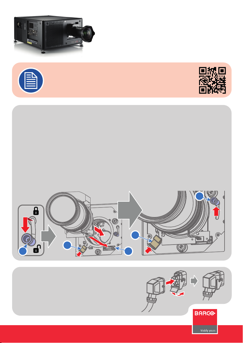
Install Lens !! ONLY USE TLD+ Zoom Lenses !!
1. Place the primary lens lock in “unlock” position. Handle (ref. 1) towards electrical socket (ref. 3).
2. If present remove the plastic protection cover from the lens holder opening.
3. Check if the secondary lens lock stands in the “unlock” position (ref. 2) .
3. Gently insert the lens. Ensure the lens connector matches the electrical socket on the lens holder.
4. Insert the lens until the connector seats into the socket.
- The secondary lens lock (ref. 2) makes an audible clicking sound when latching.
- Do not release the lens yet, keep pushing the lens against the front plate!
5. Secure the lens in the lens holder by sliding the primary lens lock handle into the “locked” position.
6. Check if the lens touches the front plate of the Lens Holder.
7. Check if the lens is really secured by trying to pull the lens out of the lens holder.
1
2
1
Connect power
Ensure that the power is properly connected to the power input.
(120-160V* / 200-240V [+/-10%, * reduced light output] )
R5906116 /02
2
3
Page 2
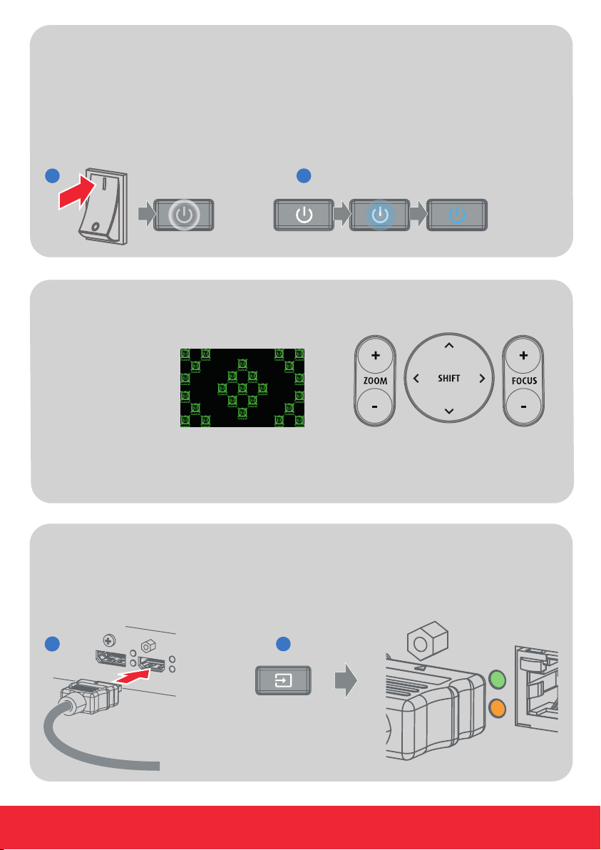
Startup
1. Power on. Turn the mains switch to on ( I ).
- Start up sequence starts. Backlight of the Power on/off button flashes WHITE.
- When start up sequence is finalized the Power on/off button lit WHITE.
2. Press the Power on/off button.
- The backlight of the Power on/off button changes from WHITE to BLUE.
- Local LCD displays a start up screen.
1
2
Adjust
1. Adjust the lens settings by pressing the LENS button or via the direct lens keys on the RCU.
Select the “Greenfocus” test pattern to adjust the lens.
TIP: Press star button (*)
to activate test pattern
2. Orientation of the unit is set as standard in table front projection mode.
Change the projector set up in the ALIGNMENT > ORIENTATION menu.
3. For Advanced adustments like Warping, Light management, etc. see User Guide of the projector.
Connect and Select source
1. Connect available sources to the appropriate input ports.
2. Select connected source: Image of selected input appears.
- The LED of the selected source lit up GREEN.
- The yellow LED indicates if sync/signal is present.
- 2 -
1
1
2
Page 3

Switch off
1. Press the Power on/off button for three seconds.
2. Wait until the after-cooling cycle is finished (approximately 30 sec.)
3. Turn the mains switch to off (’0’).
4. Unplug the power cord from the projector.
3 s
Precautions
Local Keypad
1
Menu Navigation.
2
Menu Selection.
3
Open Menu.
4
Menu Back.
5
Power On/Off.
6
OSD On/Off.
7
Input Selection.
8
Shutter Open/Close.
9
Test Patterns.
10
Lens Menu.
11
Touch Panel.
321
4
30 s
• Remove the lens before transporting the projector.
• First switch the projector to Standby mode and wait until After Cooling is
finished to switch off the main power.
• Ensure the projector is operating with clean filters.
• Do not block the ventilation in and outlets.
• External laser light can cause severe damage to the DMD. This damage is
not covered by warranty.
1 2 3 4 5 6
1011 9 8 7
- 3 -
Page 4

RCU buttons
1
2
3
4
5
6
7
8
9
10
11
12
13
14
15
24
23
22
21
20
19
18
17
16
1
Button pressed indicator.
2
Shutter Open.
3
Shutter Close.
4
Touch Panel On/Off.
5
LCD On/Off.
6
Lens Zoom.
7
Lens Shift.
8
Menu Activation.
9
Menu Selection.
10
Menu Navigation.
11
Input Selection.
12
Address button.
13
Numeric buttons.
14
Backspace
15
XLR connector.
16
Dot “.”
17
Macro button.
18
Menu Back.
19
Default button.
20
Lens Focus.
21
Color On/Off.
22
Test Patterns.
23
Power On.
24
Power Off.
25
Stereo Jack.
26
RCU On/Off.
- 4 -
25
26
Page 5

Communication Panel
321 4 5 6 7 8 9 10 11 12 13
1
WiFi antenna for wireless IP (optional)
2
12V 1A output
3
Firmware update/USB backup custom settings
4
10/100 base-T for external control over IP and Art-Net
5
DMX interface input
6
DMX interface output
7
XLR input for wired projector control
8
RS232 for serial communication
9
Sync Out 3D
10
Sync In 3D
11
Status lights
12
IR receive sensor
13
GSM antenna input (optional)
Venues & Hospitality Input (V&H)
SEL
SYNC
A
SEL
SYNC
B
TUO/NI IDSNI IDS
SEL
SYNC
C
SEL
SYNC
D
1 2 3 4 5 6 7 8
1
Quad 3G SDI channel A Input
2
Quad 3G SDI channel B Input
3
Quad 3G SDI channel C Input/Output
4
Quad 3G SDI channel D Input/Output
SEL
DP
HDMI
SYNC SYNC
5
DisplayPort Input
6
HDMI Input
7
HDBaseT Input 1
8
HDBaseT Input 2
Virtual & Augmented Reality Input (V&AR) (Optional)
SEL
HDBT 1
SEL
SYNC
HDBT 2
SEL
SYNC
DP A
1 2 3 4
1
Quad DisplayPort channel A Input
2
Quad DisplayPort channel B Input
- 5 -
SEL
SYNC
DP B
SEL
SYNC
SEL
DP C
SYNC
3
Quad DisplayPort channel C Input
4
Quad DisplayPort channel D Input
DP D
SEL
SYNC
Page 6

Button Backlight Status
Button
Power button
Shutter button
LED Status
LED
PWR (power LED)
LIGHT (Illumination LED)
ERR (error LED)
Color status
Blinking RED
Blinking BLUE
Solid BLUE
Off
Solid WHITE
Color status
Off
GREEN
ORANGE
GREEN
Off
RED toggles on/off
ORANGE toggles on/off
GREEN
Description
Projector starts up (Booting)Blinking WHITE
Projector is in StandbySolid WHITE
Error condition
Projector goes to ON mode
Projector is ON
Projector not in power ON state
Shutter is open
Shutter is closedSolid RED
- 6 -
Description
Projector powers up
Projector is in StandbyRED
Projector is ReadyORANGE
Projector is on
Light source is offOff
Light source not detectedRED
Light source is on in ECO mode
Light source is on in normal mode
Light source is on in CLO modeGREEN-ORANGE
No error
Error
Warning
IR signal receivedREDIR
IR signal acknowledged
Support
Website www.barco.com/esupport
- 6 -
Tel.:
- USA +1 866 374 7878
- EMEA +32 56 36 8019
- APAC +86 400 88 22726
 Loading...