

Page 1
SF-10V display
Installation manual
R59770542/01
10/02/2012
Page 2

Barco nv LiveDots
President Kennedypark 35, B-8500 Kortrijk
Phone: +32 56.23.32.11
Fax: +32 56.26.22.62
Support: www.barco.com/esupport
Visit us at the web: www.barco.com
Printed in China
Page 3

Changes
Barco provides this manual ’as is’ without warranty of any kind, either expressed or implied, including but not limited to the implied warranties or merchantability and fitness for a particular purpose. Barco may make improvements and/or changes to the product(s) and/or the
program(s) described in this publication at any time without notice.
This publication could contain technical inaccuracies or typographical errors. Changes are periodically made to the information in this
publication; these changes are incorporated in new editions of this publication.
The latest edition of Barco manuals can be downloaded from the Barco web site w
h
ttps://my.barco.com.
ww.barco.com or from the secured Barco web site
Page 4

Page 5

Table of contents
TABLE OF CONTENTS
1. Safety................................................................................................................ 3
1.1 Safety guidelines .................................................................................................................... 4
1.2 Important safety instructions ........................................................................................................ 5
1.3 Important warnings .................................................................................................................. 6
2. SF-10V tiles......................................................................................................... 7
2.1 SF-10Vtile ........................................................................................................................... 8
2.2 Stacking SF-10V packages ......................................................................................................... 9
3. Installation requirements . ................ ................ .................. ................ ................ .....11
3.1 Mechanical requirements for the SF-10V display ..................................................................................12
3.2 Electrical requirements for the SF-10V display. ....................................................................................14
3.3 System requirements for the Control software .. ...................................................................................15
4. System overview ..................................................................................................17
4.1 Introduction ..........................................................................................................................18
4.2 SF-10Vtile ...........................................................................................................................20
4.3 Power boxes.........................................................................................................................25
4.4 VideoProcessor ....................................................................................................................26
4.5 Controlsoftware.....................................................................................................................28
4.6 Fiberlinksystem .....................................................................................................................29
5. Physical installation ..............................................................................................31
5.1 Installation of the support structure .................................................................................................32
5.2 Mounting the SF-10V tile .. . .........................................................................................................33
6. Dimensions ................ ................ ................ .................. ................ ................ .......39
6.1 SF-10Vtile ...........................................................................................................................40
6.2 Assemblyof SF-10Vtiles............................................................................................................41
6.3 SF-10Vpackage.....................................................................................................................42
7. Specification .......................................................................................................43
7.1 Specificationsof theSF-10Vtile.....................................................................................................45
8. Order info ...........................................................................................................47
8.1 Orderinfo ............................................................................................................................48
8.2 Spare partandservice kits..........................................................................................................50
9. Environmental information ......................................................................................51
9.1 Disposalinformation.................................................................................................................52
9.2 Rohs compliance ....................................................................................................................53
R59770542 SF-10V DISPLAY 10/02/2012
1
Page 6

Table of contents
2 R59770542 SF-10V DISPLAY 10/02/2012
Page 7

1. SAFETY
About this chapter
Read this chapter attentively. It contains important information to prevent personal injury while installing the SF-10V display. Furthermore, it includes several cautions to prevent damage to the SF-10V tile. Ensure that you understand and follow all safety guidelines,
safety instructions and warnings mentioned in this chapter before installing the SF-10V display. After this chapter, additional “warnings” and “cautions” are given depending on the installation procedure. Read and follow these “warnings” and “cautions” as well.
Overview
• Safety guidelines
• Important safety instructions
• Important warnings
1. Safety
R59770542 SF-10V DISPLAY 10/02/2012
3
Page 8
1. Safety
1.1 Safety guidelines
Personal protection
WARNING: Ensure you understand an d follow all the safety guidelines, safety in structions, warnings and
cautions mentioned in this manual.
WARNING: Be aware of su spended loads.
WARNING: Wear a hard hat to reduce the risk of personal injury.
WARNING: Be careful while working with heavy loads.
WARNING: Mind your fing ers while working with heavy loads.
Installation personnel
This installation must be performed by authorized and qualified technical personnel only.
Accredited safety officers must ensure the safety of the site, construction, assembly, connection, use, dismantling, transport etc. of
such safety critical systems.
Caution
Installation should be performed only after you are thoroughly familiar with all of the proper safety checks and installation instructions.
To do otherwise increases the risk of hazards and injury to the user.
Assembly parts are designed for intended use only in conjunction with SF-10V LED displays.
Do not modify and/or replicate any component. Barco uses specific materials and manufacturing processes in order to achieve part
strength. Consult Barco for assistance with custom applications.
Always follow Barco installation instructions. Cont
The manufacturer assumes no liability for incorrect, inadequate, irresponsible or unsafe assembly of systems.
act Barco if you should have any question regarding the safety of an application.
Product care
Structural & mounting components should be kept dry, clean, lubricated (only if recommended), coated properly, and otherwise
maintained in a manner consistent with part design. Barco products must be used in a manner consistent with their design and
inspected on a routine basis for security, wear, deformation, corrosion and any other circumstances that may affect the load handling
capability of the part.
Barco recommends inspections at regular intervals for all installations and increasing in frequency for more critical installations. If
a part is found to have damage, which may cause a decrease in load capability, the part must be removed for service or replaced
immediately.
Under no circumstances are Barco parts repairable by anyone other than Barco.
4
R59770542 SF-10V DISPLAY 10/02/2012
Page 9

1.2 Important safety instructions
Instructions:
• Read these instructions.
• Keep these instructions.
• Heed all warnings.
• Follow all instructions.
• Clean only with materials or chemicals that are inert, nonabrasive, noncorrosive and non-marking. Consult the manufacturer
for further advice should any doubts exist regarding any cleaning procedure.
• Do not block ventilation openings. Install in accordance with the manufacturers instructions.
• Do not install near any heat sources such as radiators, heat registers, stoves, or other apparatus (including amplifiers) that
produce heat.
• Do not defeat the safety purpose of the polarized or grounding type plugs/sockets. If the provided sockets/plugs are damaged
then replacement of the defective parts must be undertaken immediately.
• Protect the power/data cords from being walked on or pinched particularly at plugs, convenience receptacles, and the point
where they exit from the apparatus. Replace damaged power/data cords immediately.
• Only use attachments/accessories specified by the manufacturer.
• Disconnect the power to this apparatus during lightning storms or provide suitable additional lightning protection. Unplug this
apparatus when unused for long period of time.
• Refer all servicing to qualified service technicians/personnel. Servicing is required when the apparatus has been damaged in
any way, such as power-supply cord or plug is damaged, the apparatus does not operate normally, or has been dropped.
• Use only with systems or peripherals specified by the manufacturer, or sold with the apparatus. Use caution during lifting/moving
or transporting to avoid damage by possible tipping.
1. Safety
R59770542 SF-10V DISPLAY 10/02/2012
5
Page 10

1. Safety
1.3 Important warnings
Important warnings:
Risk of electric shock:
Do not open. To reduce the risk of electric shock, do not remove cover (or back). Remove all power and data cabling before opening
the device for service purposes. No user-serviceable parts inside. Refer servicing to qualified service personnel.
Maximum and m inimum ambient temperature:
The maximum ambient temperature for the LED wall is 45°C, the minimum temperature is -20°C.
High leakag e current:
The combination of multiple tiles in an installation results in increased levels of leakage current. In order to avoid risk of electric
shock due to high leakage current, proper grounding of the installation is required.
Flammable materials:
Keep flammable materials away from the installation (such as curtains). A lot of energy is transferred into heat. The installation
should be such that the amount of air flow required for safe operation of the equipment is not compromised. Proper ventilation must
be provided.
Risk of electric shock / Risk of fire:
To protect against risk of fire caused by overloading of power cables, MAXIMUM 2 tiles may be connected in parallel. Each power
source cable supplying maximum 2 tiles should be protected by a circuit breaker or fuses rated 16 A / 250 VAC (15 A / 250 VAC in
the USA and Canada). Note that one SF-10V tile requires 220-240 VAC, 50-60 Hz, 1.56 amps at 230 VAC.
Disconnect device:
When the appliance inlets of the individual tiles are not accessible, the socket outlets supplying the rack shall be installed near the
equipment and be easily accessible, or a readily accessible general disconnect device shall be incorporated in the fixed wiring.
This equipm ent MUST be earthed:
In order to protect against risk of electric shock, the installation should be properly grounded. Defeating the purpose of the grounding
type plug will expose you to the risk of electric shock.
Power system:
It is recommended to use a TN-S power distribution system (a power distribution system with a separate neutral and grounding
conductor) in order to avoid large ground current loops due to voltage differences in the neutral conductor. The total electrical
installation should be protected by an appropriately rated disconnect switch, circuit breakers, over voltage protector and Ground Fault
Current Interrupters. The installation shall be done according to the local electrical installation codes. In Europe special attention
should be given to HD 60364, Harmonization Document for electrical installation of buildings. In Germany VDE 0100 should be
adhered to. In America, special attention should be given to the National Electrical Code, ANSI/NFPA 70.
Mains cords:
The power cords delivered with this system have special properties for safety. They are not user serviceable. If the power cords are
damaged, replace them only with new ones. Never try to repair a power cord.
Salty e nvironm ent
If install in coastal cities, the SF-10V display shall be installed 250 meters away from the shoreline horizontally in dry and cold
climates; 500 meters away from the shoreline in case of high humidity and hot climates. The high humidity and hot climate mean
the climate that the humidity is higher than 80% RH and temperature is higher than 0°C for one third of time every
6
R59770542 SF-10V DISPLAY 10/02/2012
Page 11

2. SF-10V TILES
About this chapter
This chapter described the SF-10V, modular outdoor LED tile.
Overview
• SF-10V tile
• Stacking SF-10V packages
2. SF-10V tiles
R59770542 SF-10V DISPLAY 10/02/2012
7
Page 12
2. SF-10V tiles
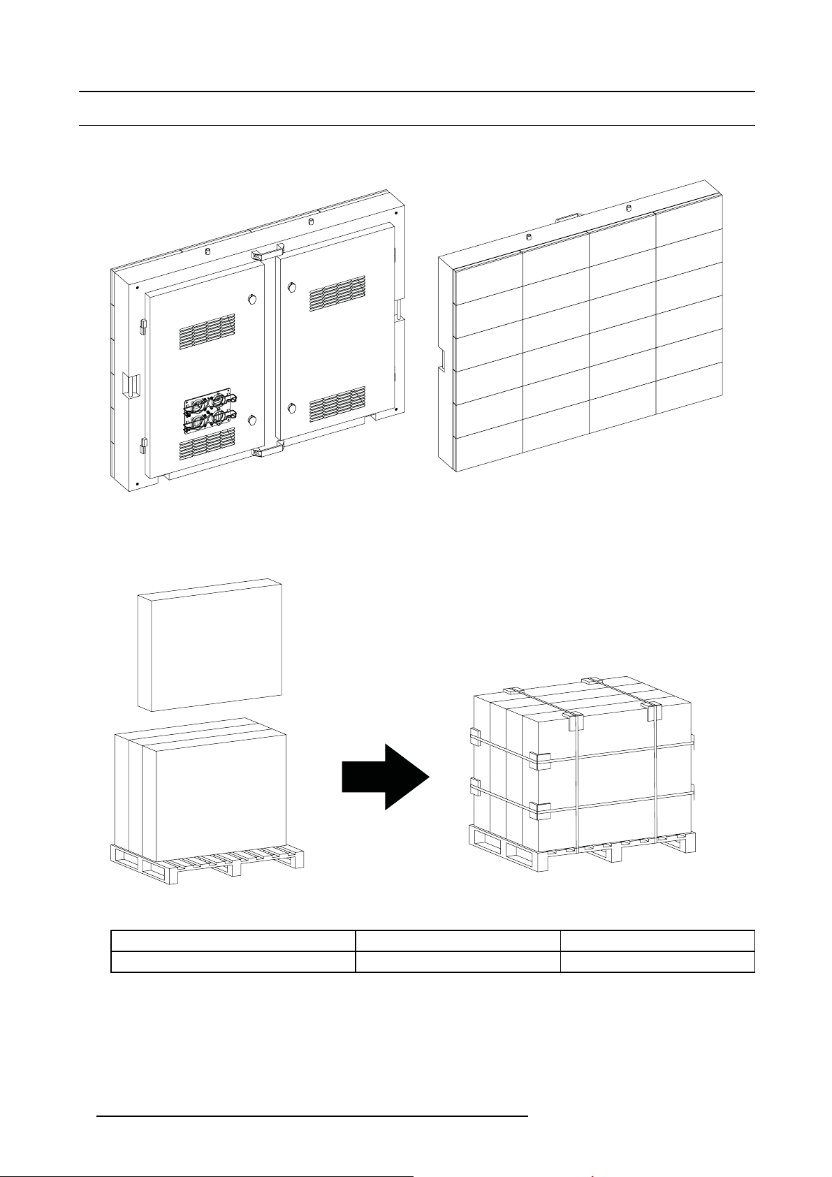
2.1 SF-10V tile
Tile overview
The front and back view of the SF-10V tile.
Image 2-1
Packing
For safe transportation, the SF-10V tiles are stored in a secure way. every tile have its separate package, Maxium 4 SF-10V packages that inner hold the tile can stand in a big wooden pallet.
Image 2-2
The weight
SF-10V 1 tile 79.5 kg R9004843
SF-10V 4 packed tiles (including pallet) 355 kg R9004843B4
8 R59770542 SF-10V DISPLAY 10/02/2012
Page 13
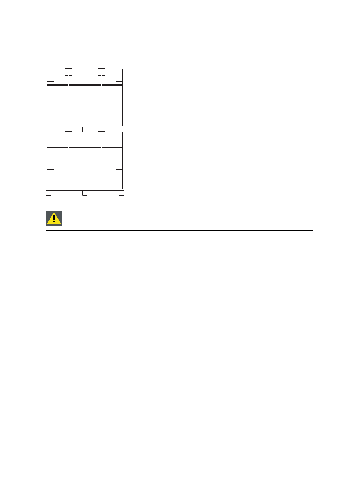
2.2 Stacking SF-10V packages
Stacking possibilities for SF-10V packages
Image 2-3
2. SF-10V tiles
WARNING: Only the configurations illustrated above can be used for stacking. Other configurations will dam-
age the SF-10V tiles.
R59770542 SF-10V DISPLAY 10/02/2012 9
Page 14

2. SF-10V tiles
10 R59770542 SF-10V DISPLAY 10/02/2012
Page 15

3. Installation requirements
3. INSTALLATION REQUIREMENTS
About this chapter
This chapter enumerate the mechanical requirements for the SF-10V display, the electrical requirements to power up the SF-10V
display and the system requirements to run the control software efficient.
Overview
• Mechanical requirements for the SF-10V display
• Electrical requirements for the SF-10V display
• System requirements for the Control software
R59770542 SF-10V DISPLAY 10/02/2012
11
Page 16
3. Installation requirements
3.1 Mechanical requirements for the SF-10V display
Support structure
The support structure can be provided and installed by the customer because they vary from system to system. Although, the
following must be taken into account and must be precisely calculated on individual basis:
1. Weight tolerances : Ensure that the support structure and the floor on which or the wall against which the support structure
has to be installed, is able to handle the complete weight of the SF-10V display.
2. Environmental conditions : Humidity, wind, temperatures, rain, salty etc.
3. Location : Outdoor, altitude, etc.
4. Ground stability
5. Front clearances : For optimal impact ensure that there is sufficient free area in front of the SF-10V display and respect the
maximum viewing distance.
6. Local regulations regarding such installations
WARNING: Never construct a SF-10V display if there is uncertainty regarding the stability of an installation
or the load holding capabilities. If there are doubts on a systems viability, consult Barco for advice on professional rigging organizations.
Individual basis
Support structures must be assessed on an individual basis. Never construct a wall if there is uncertainty regarding the stability of
an installation or the load holding capabilities. If there are doubts on a system’s viability, consult Barco for advise on professional
rigging organizations.
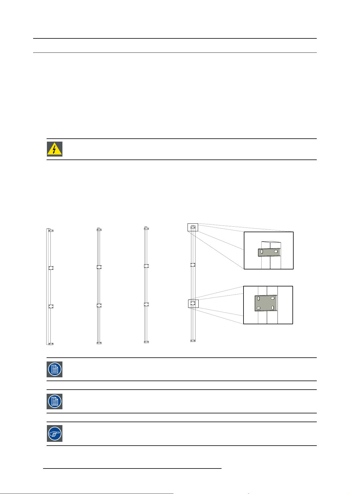
Example of a support structure
The support structure below consists of vertical I beams, when installed the tiles the bottom row tiles will directly stand on the support
structure. The mounting plates located in the back of the support structure when mounting SF-10V tiles.
Image 3-1
The drawing only shows the mounting plates’ location without the tiles, in fact the mounting plates are not
pre-installed on the support structure.
The support structure in the above example is pure illustrative for a SF-10V display consisting of 9 tiles.
It’s recommended to integrate a service platform in every other two row of the support structure . Such a
platform allows a fast and easy interven tion, if req uired.
12 R59770542 SF-10V DISPLAY 10/02/2012
Page 17
3. Installation requirements
WARNING: 90% energy is transferred into heat, which requires a certain amount of airflow at the rear of
the SF-10V display. For that sufficient free space should be available behind the display to ensure a good
ventilation. The higher the display the more free space is required.
R59770542 SF-10V DISPLAY 10/02/2012 13
Page 18
3. Installation requirements
3.2 Electrical requirements for the SF-10V display
Power requirements
One SF-10V tile requires 220-240 VAC, 50-60 Hz, 5.72 amps at 230 VAC. Note that one SF-10V tile correspond with a display surface
of 1,23 m². Power link cables are used to link the power from tile to tile. However, MAXIMUM two (2) tiles, may be connected in
parallel. So, one power source cable has to be provided per two (2) tiles. Every power source cable should be protected by a circuit
breaker or fuses rated 16 A / 250 VAC (15 A / 250 VAC in the USA and Canada).
Barco provides a range of power boxes, which meet the requirements of your SF-10V display. Contact B
for more information about power boxes and power requirements for your SF-10V display.
arco
Power system
It is recommended to use a TN-S power distribution system (a power distribution system with a separate neutral and grounding
conductor) in order to avoid large ground current loops due to voltage differences in the neutral conductor. The total electrical
installation should be protected by an appropriately rated disconnect switch, circuit bre
Current Interrupters. The installation shall be done according to the local electrical installation codes. In Europe special attention
should be given to EN 60364, the standard for electrical installation of buildings. In Germany VDE 0100 should be adhered to. In
America, special attention should be given to the National Electrical Code, ANSI/NF
akers, over voltage protector and Ground Fault
PA 70.
This equipment MUST be earthed
In order to protect against risk of electric shock, the installation should be properly grounded. Defeating the purpose of the grounding
type plug will expose you to the risk of electric shock.
14
R59770542 SF-10V DISPLAY 10/02/2012
Page 19

3. Installation requirements
3.3 System requirements for the C ontrol software
Before you begin
It is assumed you are familiar with the Windows operating system at your site.
The CD-ROM in your package contains a Windows-based installation program. You can install the software from the CD-ROM.
System requirements
Minimum specifications :
• Hardware
- PC Pentium III or equivalent, 2 GHz
- 512 Mb RAM
- Free hard disk space: 300 Mb
- XGA resolution (1024 x 768)
- Serial communication port
- Ethernet connection
• Software
- Windows 7 and Windows Vista.
Recommended specifications :
• Hardware
- PC Pentium IV or equivalent, 2.4 GHz
-1GbRAM
- 300 Mb hard disk free space
- SXGA resolution (1280 x 1024) with 32 Mb video memory
- Serial communication port
- Ethernet connection
• Software
- Windows XP Professional, Windows Vista or Windows 7
The system should be compatibility w ith either D TS or RMS.
The DTS and RMS can not compatibility with Windows Vista.
The DTS and R MS can compatibility with Window s 7 and Windows XP.
R59770542 SF-10V DISPLAY 10/02/2012 15
Page 20

3. Installation requirements
16 R59770542 SF-10V DISPLAY 10/02/2012
Page 21

4. SYSTEM OVERVIEW
About this chapter
This chapter enumerates the fundamental elements of an SF-10V screen display.
Overview
• Introduction
• SF-10V tile
• Power boxes
• Video Processor
• Control software
• Fiberlink system
4. System overview
R59770542 SF-10V DISPLAY 10/02/2012
17
Page 22

4. System overview
4.1 Introduction
The fundamental elements of an SF-10V s creen display system are:
• SF-10V tiles.
• Control PC.
• LED Image Processor.
• Power box.
• Control software.
Block diagram of a SF-10V display
LED-wall
Sources
Image 4-1
If the LED Image Processor is D 320 or Ledpro use the RS232 connection w ith the control PC
Video Processor
RS232
Control
PC
Power
box
Tile 1
Tile 2
Tile 3
18 R59770542 SF-10V DISPLAY 10/02/2012
Page 23

4. System overview
LED-wall
Sources
Image 4-2
If the LED Image Processor is DX–700 and DX-100 use the TCP/IP connection with the control PC.
Video Processor
TCP/IP
Control
PC
Power
box
Tile 1
Tile 2
Tile 3
R59770542 SF-10V DISPLAY 10/02/2012 19
Page 24

4. System overview
4.2 SF-10V tile
Introduction SF-10V tile
The SF-10V series is designed for ultra-large outdoor LED display installations. The SF-10V tile can overlay video and data sources
in their native quality. A unique video processing feature enables the creation of a visual resolution quasi double the physical resolution defined by the cluster of LED’s spread on the surface of the display. The SF-10V tile is an IP65 rating in front of side and an
IP43 rating in back of side.
Parts location of the SF-10V tile
12
5
6
9
11
2
6
5
Image 4-3
1. Hoist point.
2. Handle.
3. Air outl et.
4. Hoist point.
5. Insert nuts for fi xing tile
6. Hinge
7. Lock.
8. Lock
9. Hidden handle
10. Hinge.
11. Air inl et
12. Insert nuts for fix ing tile.
13. Adjust bloc k.
14. Lock.
15. Lock.
16. Handle.
17. Resyncer.
18. Air inl et.
19. Adjust bloc k.
20. Insert nuts for fix ing tile.
21. Hinge.
22. Hidden handle.
23. Air ou tlet.
24. Hinge.
25. Insert nuts for fix ing tile.
3
4
3
2
5
6
7
8
8
9
7
4
11
6
10
5
2
1
10
4
8
8
1
Power cables used between SF-10V tiles
To meet the demands of each SF-10V application Barco offers several lengths of power cables to link power from tile to tile. Note
that the power output port of the last tile in the power chain has to be sealed with a waterproof cap.
20
R59770542 SF-10V DISPLAY 10/02/2012
Page 25

4. System overview
Image 4-4
Power link cable of 1,5 meter (R9850241).
R59770542 SF-10V DISPLAY 10/02/2012 21
Page 26

4. System overview
Image 4-5
Dummy power plug (R9850280).
Data cables used between SF-10V tiles
To meet the demands of each SF-10V application Barco offers several lengths of data cables to link data from tile to tile. Note that
the data output port of the last SF-10V tile in the data chain has to be sealed with a dummy data plug.
22
R59770542 SF-10V DISPLAY 10/02/2012
Page 27

4. System overview
Image 4-6
Data linking ca ble of 1,5 meter (R9850210).
R59770542 SF-10V DISPLAY 10/02/2012 23
Page 28

4. System overview
Image 4-7
Dummydataplug(R9850270).
24 R59770542 SF-10V DISPLAY 10/02/2012
Page 29

4. System overview
4.3 Power boxes
General
To ensure safe and reliable operation of the SF-10V display, a suitable system for AC power distribution must be used. Though 3
party solutions may be used, several sizes and types of power distributions are available from Barco. For smaller system the “Mono
Phase Power Box” can be used, medium sized system may use on of several custom power box solutions.
rd.
Image 4-8
Mono phase power box.
CAUTION: Consult the manual(s) of the used power box for more information about installation and usage
guidelines.
Image 4-9
Custom power box.
R59770542 SF-10V DISPLAY 10/02/2012 25
Page 30

4. System overview
4.4 Video Processor
General
The Video processor processes (image processing, conversion and conditioning) all source signals for digital distribution to every
tile as well as providing a user interface for complete system setup monitoring and control. The video processor can be accessed
directly or via the control software (e.g. DTS). This software is designed as a user interface to be used in conjunction with the Video
processor and display. It should be used on a PC that’s connected to the Video processor through a serial RS232 connection.
SF-10V: Video Processor Overview
Image 4-10
D320 Processor.
Image 4-11
DX-700 Pr ocessor.
Image 4-12
LEDPro Processor.
26 R59770542 SF-10V DISPLAY 10/02/2012
Page 31

4. System overview
CAUTION: Refer to the manual(s) of the u sed vid eo proce ssor for more information about installation and
usage guide li ne s.
D320
The D320L is a video processing device, designed to drive as well Barco LED walls as large screen projectors, monitors, plasma
screens, ... etc. The D320L is capable of handling all standard output formats like SVGA, XGA, SXGA and UXGA on an analog
RGBHV and digital DVI output. The D320L digitizer allows you to control up to 4 sources on one display.
source to source or display sources together, overlay them, customize them. With analog and digital outputs which allow for the
control of displays, as well as built-in-control software, the D320L gives you control over everything from basic set-up to configuration
and advanced feature control. The D320L digitizer is a generic device. This means that a number
Devices can be chained in order to generate more windows on the output (4 windows per device). Devices can also be stacked
in order to be able to split generated output of the devices to multiple screens. For latter purpose, each input is equipped with an
active loop through.
Seamless switch from
of combinations can be made.
Display
Formated Video Data
Input 1
Input 2
Input 4
Input 9
Input 8
Input 12
SOURCE 1
SOURCE 2
SOURCE ..
Image 4-13
Analog Video
Digital Video
Control PC
Master
ViewScape - 1
Slave
ViewScape - 2
DX-700 and DX-100
The DX-700 and DX-100 is a multi-window video processor designed for use as a versatile front-end to all Barco LED products.
Image processing, LED wall configuration and control functions are adjusted from the DX-700 front panel, or from Barco’s Director
Toolset.
LedPro
The LED-PRO is a powerful all-in-one signal processor that accepts a wide range of video input signals, and processes them to
drive Barco LED displays. The LED-PRO allows you to scale visual sources and mix them in multiple ways while still maintaining
superb picture quality. LED-PRO is the ideal solution for converting RGB, HDTV, component, S-video, composite (NTSC, PAL and
SECAM), SDI, DVI, and HDSDI for use with Barco LED walls. LED-PRO has an advanced feature set that includes universal inputs,
aspect ratio conversion, memory presets, test patterns, source lock, picture adjustments, motion adaptive de-interlacing, and 3:2
and 2:2 pull down detection.
R59770542 SF-10V DISPLAY 10/02/2012
27
Page 32

4. System overview
4.5 Control software
General
The control software is designed as a graphic user interface (GUI) and can be used to control and configure the digitizer as well as
the Barco LED wall via a PC (e.g. Director toolset).
Minimum required software version: 2.04
Image 4-14
Control software “Director toolset”.
Remote management software (RMS)
The RMS-1 software is designed to configure, manage, and monitor Barco digital signage LED display systems. It supports
D320L/Lite, DMP-100 and DX-700 video processors as well as SF-10V LED tiles.
The RMS software also has a dedicated user interface which can installed on any windows based PC for remote access the LED
display system.
Image 4-15
CAUTION: R efer to the manual(s) of the used control software for more information about installation and
usage guide li ne s.
28 R59770542 SF-10V DISPLAY 10/02/2012
Page 33

4. System overview
4.6 Fiberlink system
General
If the distance between the digitizer and the LED-wall exceeds 5 meters, a fiber optic connection must be used to ensure signal
integrity and system reliability. Barco offers two complete system solutions including transmitter, fiber and receiver. The choice of
system depends on the length of cable required.
Image 4-16
“Fiberlink 2” transmitter and receiver.
CAUTION: Refer to the manual(s) of the used fi berlink system for more information about installation and
usage guide li ne s.
R59770542 SF-10V DISPLAY 10/02/2012 29
Page 34

4. System overview
30 R59770542 SF-10V DISPLAY 10/02/2012
Page 35

5. Physical installation
5. PHYSICAL INSTALLATION
About this chapter
The setup process below describes roughly the installation stages to follow to install a SF-10V display. Several stages refer to one
or more detailed and illustrated procedures which are also described in this installation manual.
WARNING: Safety fi rst. Fence off the installation area before starting to install your SF-10V display. En-
sure you read, understand and follow all safety instructions mentioned in the chapter "Safety", p
installation manual. Furthermore, make sure that all installation requirements for your SF-10V display are
fulfilled, see chapter "3. Installation requirements", "Installation requirements", page 11.
Overview
• Installation of the support structure
• Mounting the SF-10V tile
age 3 of this
R59770542 SF-10V DISPLAY 10/02/2012 31
Page 36

5. Physical installation
5.1 Installation o f the support structure
What has to be done?
The complete support structure has to be assembled and installed in its final position.
Screen supporting/securing structures vary from system to system. Consult Barco for advise on professional
rigging organizations.
SF-10V mounting plates.
Barco provides mounting plates for the SF-10V tiles which can be used to clamping the tiles to the support structure.
Image 5-1
A Middle mounting plate.
B Top / Bottom mounting plate.
A
B
32 R59770542 SF-10V DISPLAY 10/02/2012
Page 37

5.2 Mounting the SF-10V tile
Necessary tools
• 17 mm open-end wrench.
• 17 mm box-end wrench.
• 14 mm long allen key.
• Scaffold or Z-lift.
Necessary parts
• SF-10V tiles
• Four M10x90 bolts per tile (DIN931 hex cap bolts and partially thread - steel zinc plated). Reference A.
• Four M10 plain washer per tile (DIN433 - steel zinc plated). Reference B.
What has to be done?
The SF-10V tiles have to be mounted onto the support structure.
Take out the SF-10V tiles from the package.
Take out the necessary tiles from their package just before assembling them onto the support structure.
5. Physical installation
Image 5-2
CAUTION: Th e following procedure must be performed by minimum three au thorized and qualified technical
persons, which are thoroughly familiar with the product and all of the prop
To do otherwise increases the risk of hazard and injury to the user.
er safety checks of this p roduct.
SF-10V tile mounting sequence
Build up the SF-10V display row by row from bottom to top. Always start in the middle of the row and complete the row by placing
the SF-10V tiles beside one another from the middle of the row to the sides.
How to mount a SF-10V tile?
1. Bring the SF-10V tile in front of its final position on the LED-wall. Ensure the tile is in the right position, so with the hoist point on
top.
R59770542 SF-10V DISPLAY 10/02/2012 33
Page 38

5. Physical installation
2
3
5
10
4
6
7
4
9
Image 5-3
1. Adjust block
2. Hoist point.
3. Hoist point.
4. Adjust block
5. Insert nuts for fi xing tile
6 Handle
7. Insert nuts for fi xing tile
8. Handle
9. Insert nuts for fi xing tile
10. Insert nuts for fix ing tile
1
8
2. Insert the M10 plain washer (Reference B) into the bolt (Reference A)
3. Insert the bolts into the corresponding holes of the mounting plates and let the mounting plate attache to the support structure.
Caution: Two persons are required at the front of the LED-display to perform this action. Both hands must be free to insert a
tile in a LED-wall. Therefore the use of a ladder to insert a tile is forbidden. Only a solid scaffold or a Z-lift is allowed.
Tip: Use the hoist point hole on the top side to lift the SF-10V tile, using a crane and the hoist system to the desired height.
This hoist point have two functions, not only can lift the tile and also can located the two tiles when install the display.
Image 5-4
34 R59770542 SF-10V DISPLAY 10/02/2012
Page 39

5. Physical installation
B
A
4X
Image 5-5
4. Place a prevailing torque for the bolt (reference A) with the washer (reference B ) on each insert nuts of tiles. Do not fasten yet.
5. Level out the SF-10V tile. Use the adjust block in the bottom of tile for the height alignment;
Tip: For maximum adjustment space in horizontal direction place the hex cap bolts of the every first SF-10V tile that is placed
on the mounting plate in the middle of the corresponding slots.
6. Fasten the SF-10V tile. At least one person at the front keeps the SF-10V tile steady until the tile is completely fasten.
7. Release the adjust block.
R59770542 SF-10V DISPLAY 10/02/2012
35
Page 40

5. Physical installation
Example of SF-10V tile mounting
1
3
2
4
5
Image 5-6
6
How to get the height alignment between tiles
Open the back door, u
key clockwise rotate the adjust block will go up, if rotate counter-clockwise the adjust block will go down.
sing the long allen key rotate the socket head screw that located the bottom of tile as illustrated. If the allen
A
Image 5-7
B
36 R59770542 SF-10V DISPLAY 10/02/2012
B
Page 41

5. Physical installation
DVI-in
DVI-out
AC-in
AC-out
DVI-in
DVI-out
AC-in
AC-out
DVI-in
DVI-out
AC-in
AC-out
DVI-in
DVI-out
AC-in
AC-out
DVI-in
DVI-out
AC-in
AC-out
DVI-in
DVI-out
AC-in
AC-out
DVI-in
DVI-out
AC-in
AC-out
DVI-in
DVI-out
AC-in
AC-out
DVI-in
DVI-out
AC-in
AC-out
S
0v
l
10v
0v
10v
10v
0v
0v
10v
0v
DVI-in
DVI-out
AC-in
AC-out
DVI-in
DVI-out
AC-in
AC-out
DVI-in
DVI-out
AC-in
AC-out
DVI-in
DVI-out
AC-in
AC-out
DVI-in
DVI-out
AC-in
AC-out
DVI-in
DVI-out
AC-in
AC-out
0v
10v
10v
10v
10v
DVI-in
DVI-out
AC-in
AC-out
DVI-in
DVI-out
AC-in
AC-out
DVI-in
DVI-out
AC-in
AC-out
10vF-10v
A Adjust block screw.
B Long allen key(14mm)
About cabling of Data cable between tiles.
Considering the position of the data in/out sockets in SF-10Vtiles and dataI cable length, the cabling ways illustrated as follows are
the only 2 possible ways. That is, the data cable must go into the SF-10Vdisplay from the left side (back view), connect all the tiles
in a column from upper or lower corner, and then connect the next column from the other corner, repeat this from left to right (back
view) until all tiles are connected.
ata signa
Image 5-8
F-
F-1
F-1
F-1
F-
F-1
F-
F-
F-
F-
F-1
F-
Data signal
F-10v
F-1
Image 5-9
R59770542 SF-10V DISPLAY 10/02/2012 37
F-
F-
F-10v
Page 42

5. Physical installation
38 R59770542 SF-10V DISPLAY 10/02/2012
Page 43

6. DIMENSIONS
About this chapter
This chapter contains drawings of the SF-10V tiles and its package, with the most important dimensions.
Overview
• SF-10V tile
• Assembly of SF-10V tiles
• SF-10V package
6. Dimensions
R59770542 SF-10V DISPLAY 10/02/2012
39
Page 44

6. Dimensions
6.1 SF-10V tile
Dimensions of the SF-10V tile
Image 6-1
1280 mm
480 mm
1200 mm
910 mm
960 mm
M10
188mm
223.85mm
40 R59770542 SF-10V DISPLAY 10/02/2012
Page 45

6.2 Assembly of SF-10V tiles
Main dimensions of an a assembly of SF-10V tiles
6. Dimensions
80
480 mm
80
1200 mm
80
910 mm
50
910 mm
50
910 mm
1200 mm
80
1200 mm
80
Image 6-2
R59770542 SF-10V DISPLAY 10/02/2012 41
Page 46

6. Dimensions
6.3 SF-10V package
Dimensions of the SF-10V tile package containing 4 tiles.
Image 6-3
1384mm
1364mm
1424 mm
1041 mm
115 6mm
115 mm
1092 mm
1032 mm
42 R59770542 SF-10V DISPLAY 10/02/2012
Page 47

7. SPECIFICATION
7. Specification
R59770542 SF-10V DISPLAY 10/02/2012 43
Page 48

7. Specification
44 R59770542 SF-10V DISPLAY 10/02/2012
Page 49

7.1 Specifications of theSF-10V tile
Specifications of the SF-10V tile
Pixel Pitch 20mm
LED configur a tion 2R, 1G, 1B
Pixel Density (real mode) 2,500 px/m²
Pixel Density (virtual mode) 10,000 px/m²
LED density
Pixel per module HxV (real mode)
Pixel per module HxV (virtual mode)
Contrast ratio
Minimum Brightness 6,840 NIT
Typical Brightness 7,200–9,800 NIT
Color Processing 14 bit/color
Colors
Dimming 8bit
Refresh Rate (real m ode)
10,000 LEDs/m²
64x48
128x96
2,000:1
4.4 trillion
1,600 Hz
7. Specification
Refresh Rate (v irtual m ode)
Horizontal Viewing Angle (color shift) -75°/+75°
Horizontal Viewing Angle (50%
brightness)
Vertical Viewing Angle (color shirt) -40°/+30°
Vertical Viewing Angle (50%
brightness)
Max Power consumption 1,027 W/m²
Typical Power consumption 151 W/m²
Operation Power Voltage and
frequency
LED Lifetime
Environmental
Working Temperature
Tile total resolution (real/virtual) 3072/12288 px/tile
Total resolution (real/virtua l) 2500/10000 px/sqm
Operational Humidity 10–99%
Storage Temperature 10–99%
Ruggedness (IP rating, Front/Back) IP65/IP43
Sea Worthiness (IEC 60068-2-52) Sev. 2
Dimensions (HxWxD)
Module surface 1.23 m²
Weight
Installation Access back
Service Access(front/back) back
1,000 Hz
-55°/+55°
-23°/+20°
110-240V
50-60Hz
60,000
-20°C/+50°C (-4°F to 122°F)
960x1280x220 mm
37.8x50.4x7.6 inch
13.24 ft²
64.7 kg/m²
43.5 lbs/m²
79.5 kg/tile
R59770542 SF-10V DISPLAY 10/02/2012 45
Page 50

7. Specification
Compatibility
D320L/Lite
LedPro Yes
DX-700 Yes
DMP-100 No
AEC-4000 (in combination w ith DTS)
AEC-4000 (in combination w ith RMS)
Fiberlink II Ye s
CAT5 Link
DTS Software
RMS Software
XVS
Certifications CE/RohS/ETL
Yes
Yes
No
Yes
Yes
No
Yes
46 R59770542 SF-10V DISPLAY 10/02/2012
Page 51

8. ORDER INFO
About this chapter
This chapter contains the order numbers of several important SF-10V peripherals.
Overview
• Order info
• Spare part and service kits
Consult the secured partner zone on WWW.My barco.com for an updated list with order numbers of the available S F-10V products.
8. Order info
R59770542 SF-10V DISPLAY 10/02/2012 47
Page 52

8. Order info
8.1 Order info
List with order numbers for SF-10V products
Order info
Description
R9004843B1
R9852560
R9852350 BME P SLITE RAIL KIT 896
R9850241 Power link cable of 1.5 meter.
R9850250 Power link cable of 4.5 meter.
R9850260 Power link cable of 9 meter.
R9850280 Five dummy power plugs (for power output sockets)
R9850210 Data link cable of 1.5 meter
R9850220 Data link cable of 5 meter
R9850270
R9870092
R9870093
R9870094
R9870095
R9828833
R98522780
R98522781
R98522782
R9004640 BME DX-100
R9851570 BME D320L
R9851560 BME D320 LITE
R9850960 BME D320 INP DVI
R9853130
BME SF-10V 1TL BOX
BME P SLITE HOIST KIT
Two dummy data plugs (for data output sockets)
BME CATLINK DVI-MDR 10M
BME CATLINK MDR-MDR 50M
BME CATLINK MDR-MDR 10M
BME CATLINK DVI-MDR 50M
BME DMP-100 DIG MED PROCESSOR
BME DX-700 BASE UNIT
BME DX-700 INPUT MODULE
BME DX-700 DVI OUTPUT MODULE
BME P (HD) SDI IN D320/XLM
R9853350
R9853360
R9853370
R9853371 BME FIBERLINK II TX INPUT M-M
R9853361
R9851260
R9851261
R9851262 POWER VEAM CABLE 30M
R9851263 POWER VEAM CABLE 50M
R9851250 POWER BOX 3 PHASE 380V 2 OUTPUT
R9851251 POWER BOX 3 PHASE 380V 3 OUTPUT
R9851252 POWER BOX 3 PHASE 380V 4 OUTPUT
48 R59770542 SF-10V DISPLAY 10/02/2012
BME FIBERLINK II BASE UNIT
BME FIBERL II RX S-MODE
BME FIBERL II TX INP S-M
BME FIBERLINK II RX M-MODE
POWER VEAM CABLE 10M
POWER VEAM CABLE 20M
Page 53

8. Order info
R9851253
R9851254
R9850058
R838621
R838622
POWER BOX 3 PHASE 380V 5 OUTPUT
POWER BOX 3 PHASE 380V 6 OUTPUT
BME DLITE PWR BOX220
BME SF Middle Mounting Plate
BME SF Side Mounting Plate
R59770542 SF-10V DISPLAY 10/02/2012 49
Page 54

8. Order info
8.2 Spare part and service kits
General
Barco provides several kits for servicing SF-10V tiles. Below you find an order list of existing spare part and service kits. In the
future new kits can be added to this list. Contact Barco to get an updated list.
Order info
R9870040
R9870043
R9870049
R9870050
R9870052
R9870055
R9870057
R765866K
Description
BME K SF-10V LED Frame Kit
BME K SF-10V Shader Kit
BMEKSFSeriesFanKit
BME K SF Series Power Supplier
BME K SF-10V Data Cable Kit
BME K SF-10V Power Cable Kit
BME K SF Series tooling Kit
BME K SF-10 Ctr Board Kit
R765938K
BME K TF-10 I/O Box Kit
50 R59770542 SF-10V DISPLAY 10/02/2012
Page 55

9. ENVIRONMENTAL INFORMATION
Overview
• Disposal information
• Rohs compliance
9. Environmental information
R59770542 SF-10V DISPLAY 10/02/2012
51
Page 56

9. Environmental information
9.1 Disposal information
Disposal Information
Waste Electrical and Electronic Equipment
This symbol on the product indicates that, under the European Directive 2002/96/EC governing waste from electrical and
electronic equipment, this product must not be disposed of with other municipal waste. Please dispose of your waste equipment by
handing it over to a designated collection point for the recycling of waste electrical and electronic equipment. To prevent possible
harm to the environment or human health from uncontrolled waste disposal, please separate these items from other types of waste
and recycle them responsibly to promote the sustainable reuse of material resources.
For more information about recycling of this product, please contact your local city office or your municipal waste disposal service.
For details, please visit the Barco website at: h
ttp://www.barco.com/en/AboutBarco/we
Disposal of batteries in the product
This product contains batteries covered by the Directive 2006/66/EC which must be collected and disposed of separately
from municipal waste.
If the battery contains more than the specified values of lead (Pb), mercury (Hg) or cadmium (Cd), these chemical symbols will
appear below the crossed-out wheeled bin symbol.
By participating in separate collection of batteries, you will help to ensure proper disposal and to prevent potential negative effects
on the environment and human health.
ee
52
R59770542 SF-10V DISPLAY 10/02/2012
Page 57

9. Environmental information
9.2 Rohs compliance
Turkey RoHS compliance
Türkiye Cumhuriyeti: EEE Yönetmeliğine Uygundur.
[Republic of Turkey: In conformity with the EEE Regulation]
中国大陆 RoHS (Information for China ROHS compliance)
根据中国大陆《电子信息产品 污 染控制管理办法》(也称为中国大陆RoHS ),
以下部分列出了Barco产品中可能包含的有毒和/或有害物质的名称和含量。中国大陆RoHS指令包含在中国信息产业部MCV标 准:
“电 子信息产 品中有毒物质的限量要求”中。
According to the “China Administration on Control of Pollution Caused by Electronic Information Products” (Also called RoHS of
Chinese Mainland), the table below lists the names and contents of toxic and/or hazardous substances that Barco’s product may
contain. The RoHS of Chinese Mainland is included in the MCV standard of the Ministry of Informati
section “Limit Requirements of toxic substances in Electronic Information Products”.
Table of toxic and hazardous substances/elements and their content, as required by China’s management methods for controlling
pollution by electronic information products
on Industry of China, in the
零件项目( 名称)
Component Name
印制电路配件
Printed Circuit Assemblies
风扇
Fan
外接电( 线)缆
External Cables
內部 线 路
Internal wiring
电源供应 器
Power Supply Unit
金属外壳
Metal Enclosure
塑胶外壳
Plastic Enclosure
有毒有害物质或元素
Hazardous Substances or Elements
铅
(Pb)
XOOOOO
OOOOOO
OOOOOO
OOOOOO
OOOOOO
OOOOOO
OOOOOO
汞
(Hg)
镉
(Cd)
六价 铬
(Cr6+)
多溴联苯
(PBB)
多溴 二苯醚
(PBDE)
螺帽,螺钉( 栓),螺旋( 钉),垫圈 , 紧
固件
Nuts, bolts, screws, washers,
fasteners
文件说明 书
Paper Manual
光盘说明 书
CD Manual
O:表示该有毒有害物质 在 该部件所有均质材料中的含量均在 SJ/T 11363-2006 标准 规定的限量要求以下.
R59770542 SF-10V DISPLAY 10/02/2012
OOOOOO
OOOOOO
OOOOOO
53
Page 58

9. Environmental information
O: Indicates that this toxic or hazardous substance contained in all of the homogeneous materials for this part is below the limit
requirement in SJ/T11363-2006.
X:表示该有毒有害物质至少在该部件的某一均质材料中的含量超出 SJ/T 11363-2006 标准 规定的限量要求.
X : Indicates that this toxic or hazardous substance contained in at least one of the homogeneous materials used for this part is
above the limit requirement in SJ/T11363 2006.
在中国大陆销售的相应电子信息产品(EIP)都必须遵照中国大陆《电子信息产品污染控制标识要求》标准贴上 环保使用期限(EFUP)
标签。Barco产品所采用的EFUP标签(请 参阅实例,徽标内部的编号使用于制定产品)基于中国大陆的《电子信息产品 环保使用期限
通则》 标 准。
All Electronic Information Products (EIP) that are sold within Chinese Mainland must comply with the “Electronic Information Products
Pollution Control Labeling Standard” of Chinese Mainland, marked with the Environmental Friendly Use Period (EFUP) logo. The
number inside the EFUP logo that Barco uses (please refer to the photo) is based on the “Standard of Electronic Information Products
Environmental Friendly Use Period” of Chinese Mainland.
10
54 R59770542 SF-10V DISPLAY 10/02/2012
 Loading...