

Page 1
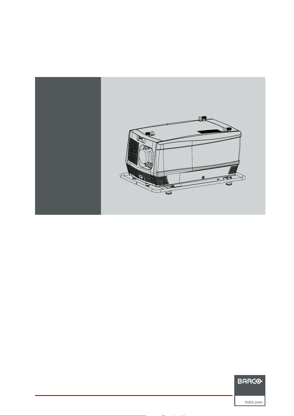
FLM HD18
R5976986/08
15/03/2010
Users manual
R9004450
Page 2

Barco nv Events
Noordlaan 5, B-8520 Kuurne
Phone: +32 56.36.82.11
Fax: +32 56.36.88.24
E-mail: sales.events@barco.com
Visit us at the web: www.barco.com
Printed in Belgium
Page 3

Changes
Barco provides this manual ’as is’ without warranty of any kind, either expressed or implied, including but not limited to the implied warranties or merchantability and fitness for a particular purpose. Barco may make improvements and/or changes to the product(s) and/or the
program(s) described in this publication at any time without notice.
This publication could contain technical inaccuracies or typographical errors. Changes are periodically made to the information in this
publication; these changes are incorporated in new editions of this publication.
Copyright ©
All rights reserved. No part of this document may be copied, reproduced or translated. It shall not other
stored in a retrieval system without the prior written consent of Barco.
wise be recorded, transmitted or
Federal Communications Commission (FCC Statement)
This equipment has been tested and found to comply with the limits for a class A digital device, pursuant to Part 15 of the FCC rules.
These limits are designed to provide reasonable protection against harmful interference when the equipment is operated in a commercial
environment. This equipment generates, uses, and can radiate radio frequency energy and, if not installed and used in accordance with
the instruction manual, may cause harmful interference to radio communications. Operation of this equipment in a residential area may
cause harmful interference, in which case the user will be responsible for correcting any interference at his own expense
EN55022/CISPR22 Class A ITE (Information Technology Equipment)
Class A ITE is a category of all other ITE which satisfies the class A ITE limits but not the class B ITE limits. Such equipment should not
be restricted in its sale but the following warning shall be included in the instructions for use:
Warning : This is a class A product. In a domestic environment this product may cause radio interference in which case the user may be
required to take adequate measures.
Guarantee and Compensation
Barco provides a guarantee relating to perfect manufacturing as pa
must immediately inspect all delivered goods for damage incurred during transport, as well as for material and manufacturing faults Barco
must be informed immediately in writing of any complaints.
The period of guarantee begins on the date of transfer of risks, in the case of special systems and software on the date of commissioning,
at latest 30 days after the transfer of risks. In the event of justified notice of complaint, Barco can repair the fault or provide a replacement
at its own discretion within an appropriate period. If this measure proves to be impossible or unsuccessful, the purchaser can demand a
reduction in the purchase price or cancellation of the contract. All other claims, in particular those relating to compensation for direct or
indirect damage, and also damage attributed to the operation of software as well as to other services provided by Barco, being a component
of the system or independent service, will be deemed invalid provided the damage is not proven to be attributed to the absence of properties
guaranteed in writing or due to the intent or gross negligence or part of Barco.
If the purchaser or a third party carries out modifications or repairs on goods delivered by Barco, or if the goods are handled incorrectly,
in particular if the systems are commissioned operated incorrectly or if, after the transfer of risks, the goods are subject to influences not
agreed upon in the contract, all guarantee claims of the purchaser will be rendered invalid. Not included in the guarantee coverage are
system failures which are attributed to programs or special electronic circuitry provided by the purchaser, e.g. interfaces. Normal wear as
well as normal maintenance are not subject to the guarantee provided by Barco either.
The environmental conditions as well as the servicing and maintenance regulations specified in the this manual must be complied with by
the customer.
rt of the legally stipulated terms of guarantee. On receipt, the purchaser
Trademarks
Brand and product names mentioned in t
All brand and product names mentioned in this manual serve as comments or examples and are not to be understood as advertising for
the products or their manufacturers.
his manual may be trademarks, registered trademarks or copyrights of their respective holders.
Software License Agreement
You should carefully read the following terms and conditions before using this software. Your use of this software indicates your acceptance
of this license agreement and warranty.
Terms and Conditions:
1. No redistribution of the software is allowed.
2. Reverse-Engineering. You may
Disclaimer of Warranty:
not reverse engineer, decompile, disassemble or alter anyhow this software product.
Page 4

This software and the accompanying files are sold “as is” and without warranties as to performance or merchantability or any other warranties whether expressed or implied. In no event shall Barco be liable for damage of any kind, loss of data, loss of profi ts, business
interruption or other pecuniary loss arising directly or indirectly. Any liability of the seller will be exclusively limited to replacement of the
product or refund of purchase price.
GNU-GPL code
If you would like a copy of the GPL source code contained in this product shipped to you on CD, please contact Barco. The cost of preparing
and mailing a CD will be charged.
Disposal Information
This equipment has required the extraction and use of natural resources for its production. It may contain hazardous substances for health
and environment. In order to avoid the dissemination of those substances in the environment and to diminish the pressure on natural
resources, we encourage you to use the appropriate take-back systems. Those systems will reuse or recycle most of the materials of your
end of life equipment in a sound way.
The crossed-out wheeled bin symbol invites you to use those systems. If you need more information on the collection, reuse and recycling
systems, please contact your local or regional waste administrator. You can also contact us for more information on the environmental
performances of our products.
Page 5

Table of contents
TABLE OF CONTENTS
1. Safety................................................................................................................. 5
1.1 General ............................................................................................................................... 5
1.2 Important safety instructions ......................................................................................................... 6
1.3 Important warnings concerning FLM flight cases.................................................................................... 8
2. General............................................................................................................... 9
2.1 Installation requirements .. ........................................................................................................... 9
2.2 Unpacking the projector ............................................................................................................. 10
2.3 Box content.......................................................................................................................... 11
2.4 FLM flight case ...................................................................................................................... 12
2.5 Projector configurations.............................................................................................................12
2.6 Projector air inlets and outlets.......................................................................................................16
2.7 Free downloadof ProjectorToolset................................................................................................. 16
3. Physical installation ..............................................................................................17
3.1 Remote control unit (RCU) . .........................................................................................................17
3.1.1 RCU battery installation.......................................................................................................18
3.1.2 RCU rugged case installation ................................................................................................19
3.1.3 RCU XLR adaptor installation ................................................................................................19
3.1.4 Using the XLR adaptor of the RCU. . . ........................................................................................ 19
3.1.5 RCU usage possibilities ......................................................................................................20
3.2 Lenses ...............................................................................................................................21
3.2.1 Available lenses...............................................................................................................21
3.2.2 Lens selection .................................................................................................................22
3.2.3 Lens formulas .................................................................................................................22
3.2.4 Lens installation ...............................................................................................................23
3.2.5 Lens removal . .................................................................................................................24
3.3 Alignment of a table mount FLM projector. . ........................................................................................25
3.4 Alignment of a ceiling mount FLM projector ........................................................................................ 26
3.5 Suspension of the FLM projector with rigging clamps. . . ...........................................................................26
4. Stacking FLM projectors.........................................................................................31
4.1 Stacking FLM projectors ............................................................................................................31
4.2 Aligning stackedFLM projectors....................................................................................................33
5. Connections........................................................................................................35
5.1 Power connection . .................................................................................................................. 35
5.2 Input source connections. . ..........................................................................................................37
5.3 Communication connections ........................................................................................................38
6. Getting started .....................................................................................................43
6.1 RCU & Local keypad ................................................................................................................43
6.2 Terminology overview ...............................................................................................................43
6.3 Operating the projector..............................................................................................................45
6.3.1 Switching on................................................................................................................... 45
6.3.2 Errors, warnings and messages during start up .. ........................................................................... 46
6.3.3 Switching to standby . .........................................................................................................46
6.3.4 Switching off................................................................................................................... 47
6.4 Using theRCU.......................................................................................................................47
6.5 Quick setup adjustments............................................................................................................49
6.5.1 Text boxes ONor OFF........................................................................................................49
6.5.2 Quick Lens Adjustment .......................................................................................................49
6.5.2.1 Quick Lens Adjustment via LENS key ................................................................................. 49
6.5.2.2 Direct Lens Adjustment (RCU).........................................................................................50
6.5.3 Quick picture inpicture .......................................................................................................50
6.5.4 Quick layout selectionwith Riggingkey......................................................................................51
6.5.5 Quick language selection . . . ..................................................................................................51
6.6 Projector address. . . .................................................................................................................52
6.6.1 Displaying and Programming addresses. . ................................................................................... 52
6.6.2 Controlling the projector ......................................................................................................53
6.7 Source selection.....................................................................................................................53
6.8 Controlling theProjector............................................................................................................. 54
7. Start up of the Adjustment Mode...............................................................................55
7.1 About the adjustment mode .........................................................................................................55
7.2 About theuse of theremote control and the local keypad......................................................................... 55
7.3 Start up the adjustment mode.......................................................................................................55
7.4 Navigation and adjustments......................................................................................................... 56
7.5 On screen menus versus LCD display menus . . ...................................................................................56
7.6 Test patterns in adjustment mode. ..................................................................................................57
7.7 Menu memory .......................................................................................................................57
R5976986 FLM HD18 15/03/2010
1
Page 6

Table of contents
8. Input menu .........................................................................................................59
8.1 Overview flow........................................................................................................................ 59
8.2 Slot module type..................................................................................................................... 59
8.2.1 About Input Setup .............................................................................................................59
8.2.2 Input configuration............................................................................................................60
8.3 Input locking . ........................................................................................................................61
8.4 Minimum delay.......................................................................................................................63
8.5 Native resolution.....................................................................................................................63
8.6 Source switching .................................................................................................................... 65
8.7 No signal .............................................................................................................................65
8.7.1 Backgroundcolor .............................................................................................................66
8.7.2 Shutdownsetting.............................................................................................................. 66
8.7.3 Shutdownretarding time......................................................................................................66
9. Image menu ........................................................................................................69
9.1 Overview flow........................................................................................................................ 69
9.2 How to select the image adjustments? . . . . . ........................................................................................70
9.3 Image Settings.......................................................................................................................70
9.3.1 Contrast .......................................................................................................................71
9.3.2 Brightness.....................................................................................................................71
9.3.3 Saturation ..................................................................................................................... 72
9.3.4 Tint (hue)......................................................................................................................73
9.3.5 Phase..........................................................................................................................73
9.3.6 Sharpness .....................................................................................................................74
9.3.7 Noise reduction ...............................................................................................................75
9.3.8 Color temperature.............................................................................................................76
9.3.8.1 Predefined color temperature..........................................................................................76
9.3.8.2 Set a custom color temperature .......................................................................................77
9.3.9 Input balance..................................................................................................................78
9.3.9.1 Introduction to Input Balance . . ........................................................................................ 78
9.3.9.2 Adjustingthe input balance ............................................................................................79
9.4 Aspect ratio ..........................................................................................................................82
9.5 Timings...............................................................................................................................83
9.5.1 Source timings ................................................................................................................83
9.5.2 Advanced settings ............................................................................................................84
9.5.3 Advanced settings, film mode detection .....................................................................................86
9.6 Image files services .................................................................................................................87
9.6.1 Files and file manipulations. ..................................................................................................87
9.6.2 Manual Load file ..............................................................................................................88
9.6.3 Delete file......................................................................................................................89
9.6.4 Delete all custom files ........................................................................................................89
9.6.5 Rename a file .................................................................................................................90
9.6.6 Copy a file.....................................................................................................................91
9.6.7 File options.................................................................................................................... 91
9.7 Save customsettings................................................................................................................92
10. Layout menu .......................................................................................................95
10.1 Overview flow........................................................................................................................95
10.2 Main window .........................................................................................................................95
10.2.1 Source selection ..............................................................................................................96
10.2.2 Size adjustment............................................................................................................... 96
10.2.3 Position adjustment...........................................................................................................99
10.3 PIP window . ........................................................................................................................100
10.3.1 Introduction to PIP . . .........................................................................................................100
10.3.2 Picture in Pictureactivation..................................................................................................101
10.3.3 Picture in Picturesource selection ..........................................................................................101
10.3.4 Picture in Picture size of the window . .......................................................................................102
10.3.5 Picture in Picture, position window .. ........................................................................................105
10.4 Layout file services.................................................................................................................106
10.4.1 Load layout . .. ................................................................................................................106
10.4.2 Rename a layout .............................................................................................................107
10.4.3 Delete a layout...............................................................................................................107
10.4.4 Copy / Save asa layout .....................................................................................................108
10.5 Zoom - Focus.......................................................................................................................109
11. Lamp menu........................................................................................................111
11.1 Overview flow.......................................................................................................................111
11.2 Lamppower mode..................................................................................................................111
11.3 Lamppower.........................................................................................................................112
11.4 Lamp Identification .................................................................................................................113
11.5 Z-axisadjustment...................................................................................................................113
12. Alignment menu................................................................................................. 115
12.1 Overview flow.......................................................................................................................115
12.2 Orientation..........................................................................................................................116
12.3 Lens adjustment ....................................................................................................................117
12.4 Side keystone.......................................................................................................................118
2
R5976986 FLM HD18 15/03/2010
Page 7

Table of contents
12.5 Warp geometry settings ............................................................................................................119
12.5.1 About Warp geometry settings ..............................................................................................119
12.5.2 WarpStatus ..................................................................................................................120
12.5.3 Horizontalkeystone correction..............................................................................................121
12.5.4 Vertical keystone correction .................................................................................................122
12.5.5 Rotation ......................................................................................................................123
12.5.6 Pincushion - Barrel correction...............................................................................................124
12.5.7 4 cornercorrection...........................................................................................................125
12.5.8 Reset warp settings.......................................................................................................... 126
12.5.9 Load warp file................................................................................................................127
12.6 Contrast enhancement .............................................................................................................128
12.7 Blanking.............................................................................................................................128
12.8 Gamma .............................................................................................................................130
12.9 Internalpattern......................................................................................................................130
12.10 Color space.........................................................................................................................131
12.11 ScenergiX...........................................................................................................................132
12.11.1 Introduction. . .................................................................................................................132
12.11.2 Preparations. . ................................................................................................................133
12.11.3 ScenergiX activation .........................................................................................................133
12.11.4 ScenergiX overlap zone (horizontal ScenergiX) .. ..........................................................................134
12.11.5 ScenergiX overlap zone (vertical ScenergiX) ...............................................................................135
12.11.6 ScenergiX size adjustment (White level) . . ..................................................................................137
12.11.7 Adjusting the black level of the images . .. ..................................................................................139
13. Projector control ................................................................................................ 143
13.1 Overview flow.......................................................................................................................143
13.2 Projector address . . .................................................................................................................144
13.2.1 Individual projector address .................................................................................................144
13.2.2 Common address ............................................................................................................145
13.3 Serial communication...............................................................................................................146
13.3.1 Baud rate setup............................................................................................................. . 146
13.3.2 Interface standard............................................................................................................146
13.3.3 RS422 termination........................................................................................................... 147
13.4 Network .............................................................................................................................147
13.4.1 Introduction to a Network connection .......................................................................................148
13.4.2 DHCP setup . . ................................................................................................................148
13.4.3 IP-address set up ............................................................................................................149
13.4.4 Subnet-mask set up..........................................................................................................149
13.4.5 Default Gatewayset up......................................................................................................150
13.5 IR control switching.................................................................................................................151
13.6 Art-Net DMX ........................................................................................................................151
13.6.1 DMX address. ................................................................................................................152
13.6.2 DMX universe................................................................................................................ 152
13.6.3 DMX monitor .................................................................................................................153
13.6.4 DMX mode . . . ................................................................................................................154
13.6.5 Art-Net activation.............................................................................................................155
13.6.6 Home lens at startup.........................................................................................................155
13.7 Buttons..............................................................................................................................156
13.7.1 Standby button ...............................................................................................................156
13.7.2 APA (auto) button............................................................................................................ 157
13.7.3 Shortcut keys.................................................................................................................157
13.8 Menuposition.......................................................................................................................158
13.8.1 On screen menu .............................................................................................................158
13.8.2 Bar scale .....................................................................................................................159
13.9 LocalLCD...........................................................................................................................159
13.9.1 Local LCD time out...........................................................................................................159
13.9.2 Local LCD contrast.......................................................................................................... . 160
13.10 Language selection. ................................................................................................................160
14. Service menu..................................................................................................... 163
14.1 Overview flow.......................................................................................................................163
14.2 Identification ........................................................................................................................163
14.3 Diagnosis ...........................................................................................................................165
14.3.1 How to start up the diagnosis? ..............................................................................................165
14.3.2 Versions ......................................................................................................................165
14.3.3 Voltages ......................................................................................................................166
14.3.4 I²C diagnosis . ................................................................................................................167
14.3.5 Temperatures ................................................................................................................167
14.3.6 Fan speeds overview ........................................................................................................168
14.3.7 SPI............................................................................................................................169
14.3.8 Error logging overview....................................................................................................... 170
14.4 Convergence .......................................................................................................................170
14.5 Internalservice patterns............................................................................................................171
14.6 Restore factorydefaults............................................................................................................172
14.7 Reset formatter .....................................................................................................................173
14.8 Save custom settings...............................................................................................................174
R5976986 FLM HD18 15/03/2010
3
Page 8

Table of contents
14.9 Refill mode.. . .......................................................................................................................174
14.10 Broadcast mode....................................................................................................................175
14.11 USB memory .......................................................................................................................176
15. Maintenance...................................................................................................... 179
15.1 Replacement of the dust filter onthe frontside ...................................................................................179
15.2 Replacement of the dust filter onthe bottom side.................................................................................180
15.3 Replacement of the dust filter onthe topside.....................................................................................181
15.4 Pressure verification of the liquid cooling circuit...................................................................................181
15.5 Cleaning the lens ... ................................................................................................................182
15.6 Cleaning the exterior of the projector ..............................................................................................182
16. Servicing.......................................................................................................... 183
16.1 Removal of the lamp house ........................................................................................................183
16.2 Removal of the input & communication unit .......................................................................................184
16.3 Removal of an input module .......................................................................................................185
16.4 Installation of the lamp house ......................................................................................................186
16.5 Installation of the input & communication unit . . . ..................................................................................187
16.6 Installation of an input module .....................................................................................................188
16.7 Realignment of the lamp in its reflector............................................................................................189
17. Removal of the projector covers ............................................................................. 191
17.1 Removalof the frontcover .........................................................................................................191
17.2 Removalof the sidecover..........................................................................................................192
17.3 Removalof the lampcover.........................................................................................................193
17.4 Removal of the input cover.........................................................................................................193
17.5 Installation ofthe front cover .......................................................................................................194
17.6 Installation ofthe side cover .......................................................................................................195
17.7 Installation ofthe lamp cover.......................................................................................................196
17.8 Installation ofthe input cover.......................................................................................................197
A. Dimensions ........................................................................................................ 199
A.1 Dimensions of the FLM HD18......................................................................................................199
A.2 Dimensions of the FLM flight case.................................................................................................200
A.3 Dimensions of the rigging clamps. .................................................................................................201
B. Standard Source Files ........................................................................................... 203
B.1 Table overview......................................................................................................................203
C. DMX chart.......................................................................................................... 205
C.1 DMX chart, basic ...................................................................................................................205
C.2 DMX chart, Extended ...............................................................................................................206
C.3 DMX chart, Full.....................................................................................................................207
D. Troubleshooting ... . . .. . . .. . ... ... . .. . . .. . . .. . ... . .. . ... . .. . . .. . ... . .. . ... . .. . . .. . . .. . ... . .. . ... . .. . . .. . ... . .. . ... 211
D.1 Error codes . ........................................................................................................................211
E. Specifications ..................................................................................................... 219
E.1 Specifications FLM HD18 ..........................................................................................................219
E.2 Specifications FLM 5 cable input (multi purpose) .................................................................................221
E.3 Specifications FLM HDSDI – SDI input . .. . . .......................................................................................222
E.4 Specifications FLM DVI input ......................................................................................................223
E.5 Specifications FLM DVI HDCP input...............................................................................................223
F. Order info........................................................................................................... 225
F.1 Sparepart orderinfo ...............................................................................................................225
Glossary ............................................................................................................... 227
Index.................................................................................................................... 229
4 R5976986 FLM HD18 15/03/2010
Page 9

1. SAFETY
About this chapter
Read this chapter attentively. It contains important information to prevent personal injury while installing and using an FLM HD18
projector. Furthermore, it includes several cautions to prevent damage to the FLM HD18. Ensure that you understand and follow
all safety guidelines, safety instructions and warnings mentioned in this chapter before installing your FLM projector. After this
chapter, additional “warnings” and “cautions” are given depending on the installation procedure. Read and follow these “warnings”
and “cautions” as well.
Overview
• General
• Important safety instructions
• Important warnings concerning FLM flight cases
1.1 General
Notice on safety
This equipment is built in accordance with the requirements of the international safety standards IEC60950-1, EN60950-1,
UL60950-1 and CAN/CSA C22.2 No.60950-1, which are the safety standards of information technology equipment including
electrical business equipment. These safety standards impose important requirements on the use of safety critical components,
materials and insulation, in order to protect the user or operator against risk of electric shock and energy hazard, and having
access to live parts. Safety standards also impose limits to the internal and external temperature rises, radiation levels, mechanical
stability and strength, enclosure construction and protection against the risk of fire. Simulated single fault condition testing ensures
the safety of the equipment to the user even when the equipment’s normal operation fails.
1. Safety
Restricted access location
The FLM HD18 may only be installed in a restricted access location, due to the temperature rise of parts of the equipment (air outlet).
Restricted access location
A location for equipment where both of the following paragraphs apply:
1) Access can only be gained by SERVICE PERSONS or by USERS who have been instructed about the reasons for
the restriction applied to the location and about the precautions that shall be taken.
2) Access is through the use of the tool or lock and key, or other means of security, and is controlled by the authority
responsible for the location.
Installation instructions
• Before operating this equipment please read this manual thoroughly, and retain it for future reference.
• Installation and preliminary adjustments should be performed by qualified Barco personnel or by authorized Barco service dealers.
• All warnings on the projector and in the documentation manuals should be adhered to.
• All instructions for operating and use of this equipment must be followed precisely.
Safety indication on the product
Risk of electrical shock. Do not open. To reduce the risk of electrical shock, do not remove the projector’s covers. No user-serviceable parts inside. Refer servicing to qualified service personnel.
• The lightning flash with an arrowhead within a triangle is intended to tell the user that parts inside this product may cause a risk
of electrical shock to persons.
• The exclamation point within a triangle is intended to tell the user that important operating and/or servicing instructions are
included in the technical documentation for this equipment.
Definition of “qualified service technicians” or ”qualified technicians”: Persons having appropriate technical
training and experience necessary to be aware of hazards to which they are exposed in performing a task and
of measures to minimize the danger to themselves or other persons.
Owners record
The part number and serial number are located at the right side of the projector. Record these numbers in the spaces provided
below. Refer to them whenever you call upon your Barco dealer regarding this product.
R5976986 FLM HD18 15/03/2010
5
Page 10

1. Safety
Product article number
Product serial number
Dealer
1.2 Important safety instructions
To prevent the risk of electrical shock
• This product should be operated from a mono phase AC power source. Power input voltage range must be between 200-240
VAC, 50–60 Hz, 20 amps at 230 VAC
• The power cord of the FLM HD18 is equipped with a 3-wire grounding plug, a plug having a third (grounding) pin. This plug will
only fit into a grounding-type EN60-309 power outlet. This is a safety feature. Mains power cord with EN60-309 plug:
L
N
E
Warning: This apparatus must be grounded (earthed) via the supplied 3 conductor AC power cable. If the supplied power
cable is not the correct one, consult your dealer.
If you are unable to insert the plug into the outlet, contact your electrician to replace your obsolete outlet. Do not defeat the
purpose of the grounding-type plug.
The wires of the power cord are colored in accordance with the following code:
EN60-309
International plug 32 ampere:
Green/Yellow: ground.
Blue: neutral.
Brown: line (live)
• Do not allow anything to rest on the power cord. Do not locate this product where persons will walk on the cord. To disconnect
the cord, pull it out by the plug. Never pull the cord itself.
• If an extension cord is used with this product, make sure that the total of the ampere ratings on the products plugged into the
extension cord does not exceed the extension cord ampere rating.
• Use only the power cord supplied with your projector. While appearing to be similar, other power cords have not been safety
tested at the factory and may not be used to power the projector. For a replace
• Never push objects of any kind into this product through cabinet slots as they may touch dangerous voltage points or short out
parts that could result in a risk of fire or electrical shock.
• Never spill liquid of any kind on the product. Should any liquid or solid object fall into the cabinet, unplug the set and have it
checked by qualified service personnel before resuming operations.
• Lightning - For added protection for this video product during a lightning storm, or when it is left unattended and unused for
long periods of time, unplug it from the wall outlet. This will prevent damage to the projector due to lightning and AC power-line
surges.
North American plug 30 ampere:
Green/Yellow or Green: ground.
Blue or White: neutral.
Brown or Black: line (live)
ment power cord, contact your dealer.
To prevent personal injury
• Caution: High pressure lamp may explode if improperly handled. Refer servicing to qualified service personnel. The customer
should never attempt to disassemble the lamp casing or to dispose of the lamp casing other than by returning it to Barco.
• To prevent injury and physical damage, always read this manual and all labels on the system before inserting the lamp casing,
connecting to the wall outlet or adjusting the projector.
• To prevent injury, take note of the weight of the projector. Minimum 4 persons are needed to carry the projector.
• To prevent injury, ensure that the lens and all cover plates are correctly installed. See installation procedures.
• Warning: high intensity light beam. NEVER look into the lens ! High luminance could result in damage to the eye.
• Before attempting to remove any of the projector’s covers, you must turn off the projector and disconnect from the wall outlet.
• When performing setup work to a ceiling mounted projector, to prevent injury caused by falling objects or the system, set out
a keep out area.
• Consult a professional structural engineer prior to suspending the projector from a structure not intended for that use. Always
ensure that the working load limit of the structure can handle the load of the projector.
• Never stack more than two (2) FLM projectors in a hanging configuration (truss) and never stack more than three (3) FLM
projectors in a base stand configuration (table mount).
• The power input at the projector side is considered as the disconnect device. When required to switch off the projector, to
access parts inside, always disconnect the power cord at the projector side. In case the power input at the projector side is not
accessible (e.g. ceiling mount), the socket outlet supplying the projector shall be installed nearby the projector and be easily
accessible, or a readily accessible general disconnect device shall be incorporated in the fixed wiring.
• Do not place this equipment on an unstable cart, stand, or table. The product may fall, causing serious damage to it and
possible injury to the user.
6
R5976986 FLM HD18 15/03/2010
Page 11

1. Safety
• When mounting the projector to the ceiling or to a rigging system, always mount security chains.
• Warning: Protection from ultraviolet radiation: Do not look directly in the light beam. The lamp contained in this product is
an intense source of light and heat. One component of the light emitted from this lamp is ultraviolet light. Potential eye and skin
hazards are present when the lamp is energized due to ultraviolet radiation. Avoid unnecessary exposure. Protect yourself and
your employees by making them aware of the hazards and how to protect themselves. Protecting the skin can be accomplished
by wearing tightly woven garments and gloves. Protecting the eyes from UV can be accomplished by wearing safety glasses
that are designed to provide UV protection. In addition to the UV, the visible light from the lamp is intense and should also be
considered when choosing protective eye wear.
• Exposure to UV radiation: Some medications are known to make individuals extra sensitive to UV radiation. The American
Conference of Governmental Industrial Hygienists (ACGIH) recommends occupational UV exposure for an-8hour day to be
less than 0.1 microwatts per square centimeters of effective UV radiation. An evaluation of the workplace is advised to assure
employees are not exposed to cumulative radiation levels exceeding these government guidelines.
To prevent projector damage
• If the Air Filters are not regularly replaced, the air flow inside the projector could be disrupted, causing overheating. Overheating
may lead to the projector shutting down during operation.
• In order to ensure that correct airflow is maintained, and that the projector complies with electromagnetic compatibility (EMC)
requirements, it should always be operated with all of it’s covers in place.
• Slots and openings in the cabinet are provided for ventilation. To ensure reliable operation of the product and to protect it from
overheating, these openings must not be blocked or covered. The openings should never be blocked by placing the product
on a bed, sofa, rug, or other similar surface. This product should never be placed near or over a radiator or heat register. The
projector should not be placed in a built-in installation or enclosure unless proper ventilation is provided.
• Do not block the projector cooling fans or free air movement under and around the projector. Loose papers or other objects
may not be nearer to the projector than 10 cm (4") on any side.
• The projector must always be mounted in a manner which ensures free flow of air into its air inlets and unimpeded evacuation
of the hot air exhausted from its cooling system. Heat sensitive materials should not be placed in the path of the exhausted air.
Leave at least a free safety area of 1 meter (40”) at the rear of the projector.
• Ensure that nothing can be spilled on, or dropped inside the projector. If this does happen, switch off and unplug the mains
supply immediately. Do not operate the projector again until it has been checked by qualified service technicians.
• Consult a professional structural engineer prior to suspending the ceiling mount from a structure not intended for that use.
Always ensure the working load limit of the structure supporting the projector.
• Do not use this equipment near water.
• Special care should be used when DLP projectors are used in the same room as high power laser equipment. Direct or indirect
hitting of a laser beam on to the lens can severely damage the Digital Mirror Devices
• Save the original shipping carton and packing material; they will come in handy if you ever have to ship your equipment. For
maximum protection, repack your set as it was originally packed at the factory.
• Unplug this product from the wall outlet before cleaning. Do not use liquid cleaners or aerosol cleaners. Use a damp cloth for
cleaning. Never use strong solvents, such as thinner or benzine, or abrasive cleaners, since these will damage the cabinet.
Stubborn stains may be removed with a cloth lightly dampened with mild detergent solution.
• To ensure the highest optical performance and res
coating, therefore, avoid touching the lens. To remove dust on the lens, use a soft dry cloth. Do not use a damp cloth, detergent
solution, or thinner.
olution, the projection lenses are specially treated with an anti-reflective
TM
in which case there is a loss of warranty.
To prevent battery explosion
• Danger of explosion if battery is incorrectly installed.
• Replace only with the same or equivalent type recommended by the manufacturer.
• Dispose of used batteries according to the manu
facturer’s instruction.
To prevent fire hazard
• Warning “Risk of fire”. Do not place flammable or combustible materials near the projector !
This projector radiates heat on its external surfaces and from ventilation ducts during normal operation, which is both normal
and safe. Exposing flammable or combustible materials into close proximity of this projector could result in the spontaneous
ignition of that material, resulting in a fire. For this reason, it is absolutely necessary to leave an “exclusion zone” around all
external surfaces of the projector whereby no flammable or combustible materials are present. The exclusion zone must be not
less than 40 cm (16”) for all Barco DLP projectors. The exclusion zone on the lens side must be at least 2 meter (80”).
• Do not cover the projector or the lens with any material while the projector is in operation.
• To reduce the lamp heat of the project
minutes. Then the projector may be switched off with the power switch.
• Mount the projector in a well ventilated area away from sources of ignition and out of direct sun light.
• Never expose the projector to rain or moisture.
• In the event of fire, use sand, CO
• This product should never be placed near or over a radiator or heat register.
• This projector should not be placed in a built-in installation or enclosure unless proper ventilation is provided.
• Projection rooms must be well ventilated or cooled in order to avoid build up of heat.
R5976986 FLM HD18 15/03/2010
or, switch the projector first to standby and let the projector lamp cool down for at least 5
, or dry powder fire extinguishers; never use water on an electrical fire.
2
7
Page 12

1. Safety
On servicing
• Do not attempt to service this product yourself, as opening or removing covers may expose you to dangerous voltage potentials
and risk of electric shock.
• Refer all servicing to qualified service personnel.
• Fence off a restricted area of at least 3 meters around the projector using an eye-catching fence and “KEEP OUT” sings. This
to prevent unauthorized persons coming near the projector during servicing.
• Unplug this product from the wall outlet and refer servicing to qualified service technicians under the following conditions:
- When the power cord or plug is damaged or frayed.
- If liquid has been spilled into the equipment.
- If the product has been exposed to rain or water.
- If the product does not operate normally when the operating instructions are followed. Adjust only those controls that are
covered by the operating instructions since improper adjustment of the other controls may result in damage and will often
require extensive work by a qualified technician to restore the product to normal operation.
- If the product has been dropped or the cabinet has been damaged.
- If the product exhibits a distinct change in performance, indicating a need for service.
• Replacement parts: When replacement parts are required, be sure the service technician has used original Barco replacement
parts or authorized replacement parts which have the same characteristics as the Barco original part. Unauthorized substitutions may result in degraded performance and reliability, fire, electric shock or other hazards. Unauthorized substitutions may
void warranty.
• Safety check: Upon completion of any service or repairs to this projector, ask the service technician to perform safety checks
to determine that the product is in proper operating condition.
1.3 Important warnings concerning FLM flight cases
Important warnings concerning stacking/transporting FLM rental flight cases
• Stack maximum two (2) FLM rental flight cases high. Never higher.
• Surface on which flight case is standing must be level to ensure that the total load is evenly spread out among the four wheels.
The surface must also be able to support the load safely.
• Before stacking or transporting flight cases, check the wheels and their fixation screws for wear or defects.
• Before stacking or transporting flight cases, check that the four lock handles on each flight case are in good working order and
locked securely.
• When stacked, make sure the wheels of the upper flight case are precisely positioned in the stacking dishes of the flight case
below.
•Stackedflight cases may not be moved. Before stacking, the lower flight case must already be in its final resting position before
placing the second upon it.
• Never stack loaded flight cases in a truck or other transport medium
• In the event of a wheel breaking, flight cases must be rigidly strapped tight to prevent a stack collapsing.
• Use an appropriate forklift to raise flight cases and take the necessary precautions to avoid personnel injury.
, unless each flight case is rigidly strapped tight.
8
R5976986 FLM HD18 15/03/2010
Page 13

2. GENERAL
About this chapter
Read this chapter before installing your FLM HD18. It contains important information concerning installation requirements for the
FLM HD18, such as minimum and maximum allowed ambient temperature, humidity conditions, required safety area around the
installed projector, required power net, compatible signal sources, etc.
Furthermore, careful consideration of things such as image size, ambient light level, projector placement and type of screen to use
are critical to the optimum use of the projection system.
Overview
• Installation requirements
• Unpacking the projector
• Box content
•FLMflight case
• Projector configurations
• Projector air inlets and outlets
• Free download of Projector Toolset
2.1 Installation requirements
2. General
Ambient temperature conditions
The maximum allowed ambient temperature for an operating Barco FLM HD18 may not exceed +40 ºC (+104 ºF).
The minimum allowed ambient temperature for an operating Barco FLM HD18 may not drop below +10 ºC (+50 ºF).
The projector will not operate if the ambient air temperature falls outside this range (+10 ºC → +40 ºC or +50 ºF → +104 ºF). Be
aware that room heat rises to the ceiling. Check if the temperature near the installation site is not excessive.
The minimum storage temperature is -35 ºC (-31 ºF) and the maximum storage temperature is +65 ºC (+149 ºF).
Humidity conditions
Storage: 0 to 98% relative humidity, non-condensing.
Operation: 0 to 95% relative humidity, non-condensing.
Projector weight
Do not underestimate the weight of one Barco FLM HD18, which is about ±100 kg (±225 lb.). Be sure that the table or truss installation on which the projector(s) has to be installed is capable of handling five (5) times the complete load of the complete system.
Power requirements
One Barco FLM HD18 requires 200-240 VAC, 50–60 Hz, 20 amps at 230 VAC.
Clean air environment
A projector must always be mounted in a manner which ensures the free flow of clean air into the projectors ventilation inlets. For
installations in environments where the projector is subject to airborne contaminants such as that produced by smoke machines or
similar (these deposit a thin layer of greasy residue upon the projectors internal optics and imaging electronic surfaces, degrading
performance), then it is highly advisable and desirable to have this contamination removed prior to it reaching the projectors clean
air supply. Devices or structures to extract or shield contaminated air well away from the projector are a prerequisite, if this is not a
feasible solution then measures to relocate the projector to a clean air environment should be considered.
Only ever use the manufacturer’s recommended cleaning kit which has been specifically designed for cleaning optical parts, never
use industrial strength cleaners on the projector’s optics as these will degrade optical coatings and damage sensitive optoelectronics
components. Failure to take suitable precautions to protect the projector from the effects of persistent and prolonged air contaminants will culminate in extensive and irreversible ingrained optical damage. At this stage cleaning of the internal optical units will
be noneffective and impracticable. Damage of this nature is under no circumstances covered under the manufacturer’s warranty
and may deem the warranty null and void. In such a case the client shall be held solely responsible for all costs incurred during any
repair. It is the clients responsibility to ensure at all times that the projector is protected from the harmful effects of hostile airborne
particles in the environment of the projector. The manufacturer reserves the right to refuse repair if a projector has been subject to
knowingly neglect, abandon or improper use.
Which screen type ?
There are two major categories of screens used for projection equipment. Those used for front projected images and those for rear
projection applications.
R5976986 FLM HD18 15/03/2010
9
Page 14
2. General
Screens are rated by how much light they reflect (or transmit in the case of rear projection systems) given a determined amount
of light projected toward them. The ‘GAIN’ of a screen is the term used. Front and rear screens are both rated in terms of gain.
The gain of screens range from a white matte screen with a gain of 1 (x 1) to a brushed aluminized screen with a gain of 10 (x 10)
or more. The choice between higher and lower gain screens is largely a matter of personal preference and another consideration
called the viewing angle. In considering the type of screen to choose, determine where the viewers will be located and go for the
highest gain screen possible. A high gain screen will provide a brighter picture but reduce the viewing angle. For more information
about screens, contact your local screen supplier.
What image size? How big should the image be?
The projector is designed for projecting an image size : minimum 1 meter (3.3 ft.) to maximum 18 meter (59 ft.) (depending on the
ambient light conditions), with an aspect ratio of 16 to 9 (recommended between 1 m (3.3ft) - 12 m (39.4ft)).
2.2 Unpacking the projector
What has to be done ?
At delivery the projector is packed in a carton box upon a wooden pallet and secured with banding and fastening clips. Furthermore,
to provide protection during transportation, the projector is surrounded with foam. Once the projector is arrived at the installation
site, it has to be removed from the carton box and wooden pallet in a safe manner without damaging the projector.
Necessary tools
• Side cutter.
• 8 mm Allen key.
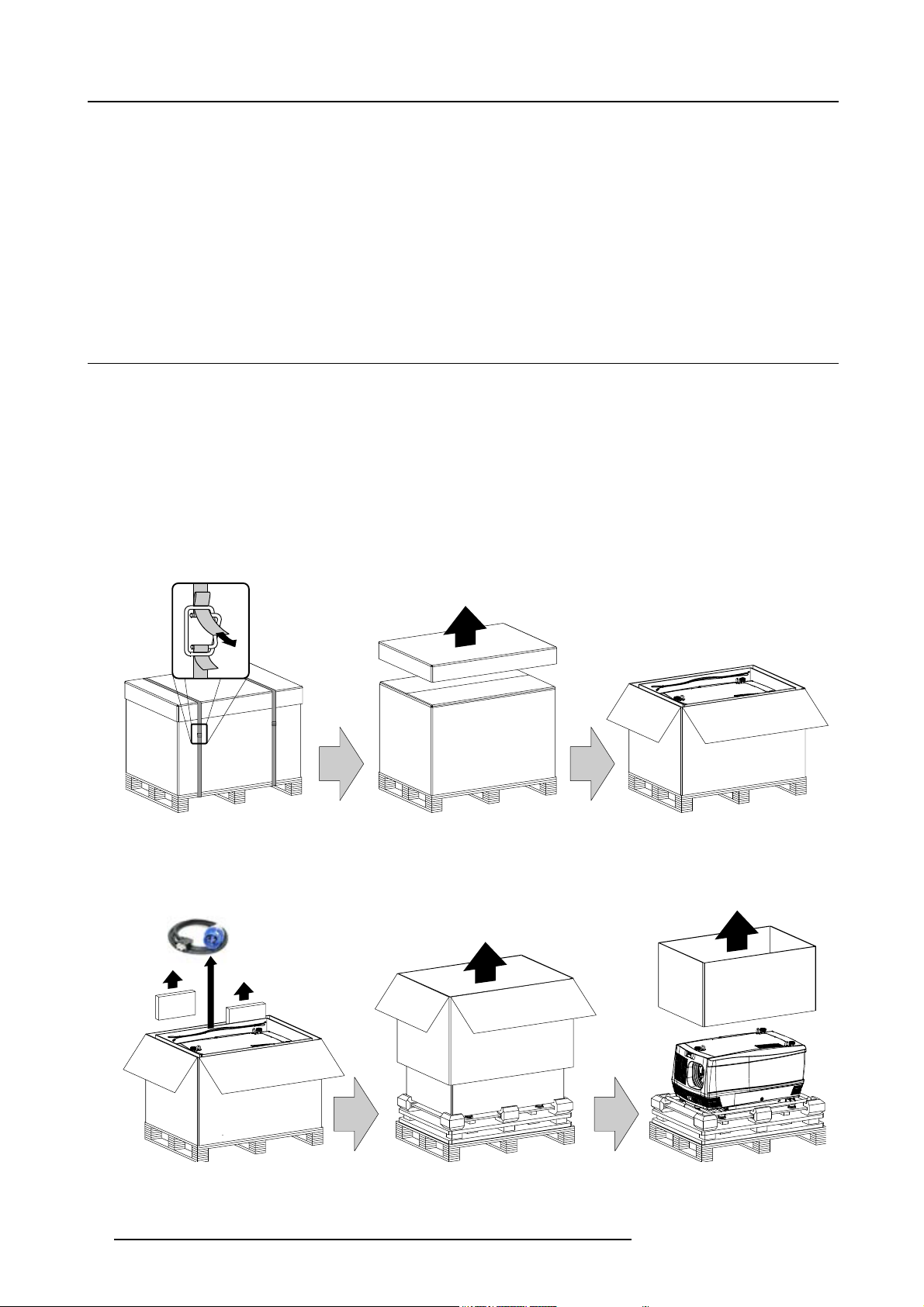
How to unpack the projector ?
1. Remove the banding around the carton box, by releasing the fastening clips as illustrated, and remove the top cover.
Image 2-1
2. Remove the power cord, which is attached to the packaging with a cable ties, and the two smaller carton boxes, located between
the inner carton sleeve and outer carton box.
Note: The two smaller carton boxes contain the manuals, the remote control unit (RCU), two standard batteries size AA and
four rigging clamps for projector suspension.
Image 2-2
10 R5976986 FLM HD18 15/03/2010
Page 15
2. General
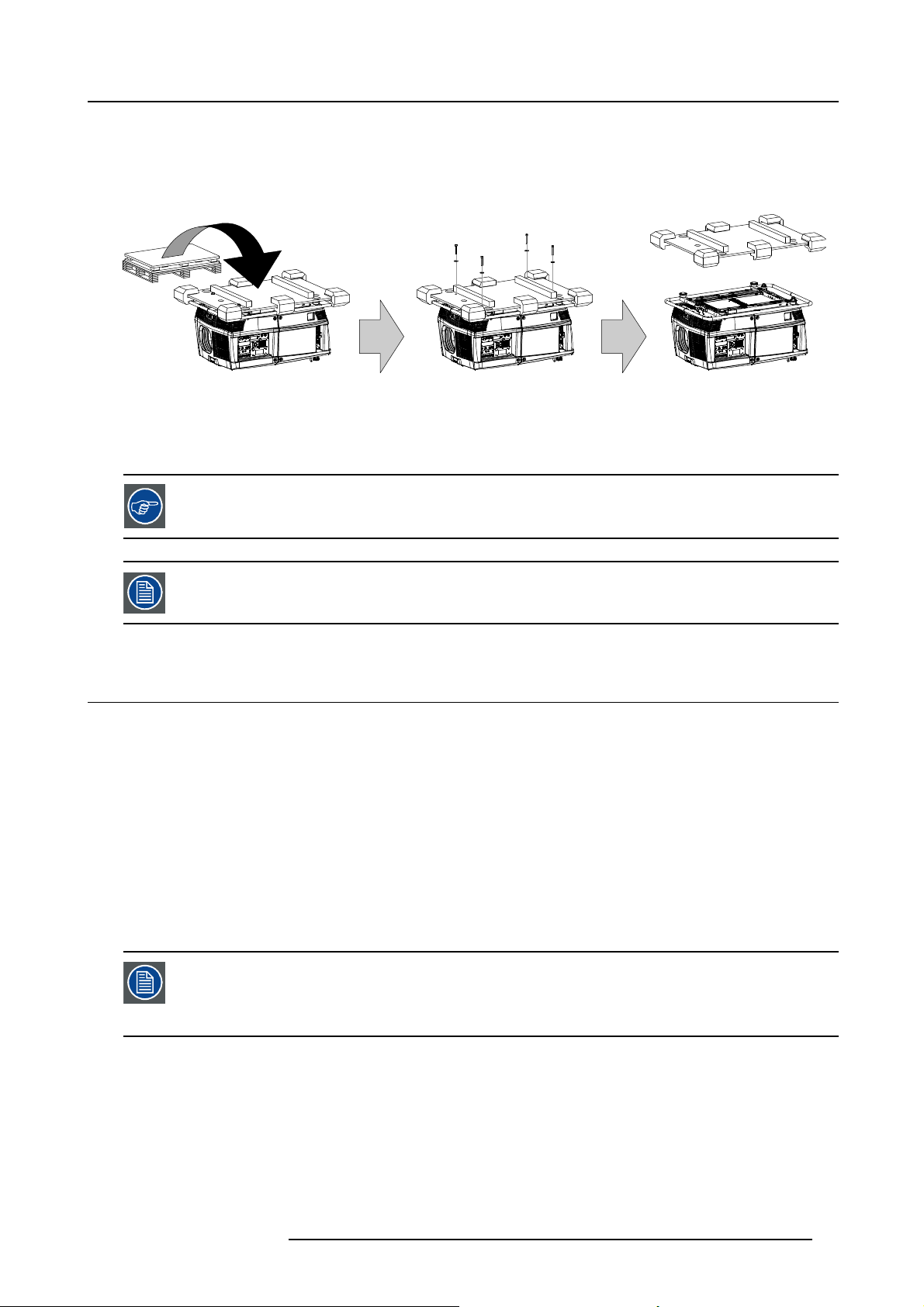
3. Remove the carton box, the inner carton sleeve and the foam around the projector. See image 2-2.
Note: The projector is still attached to a wooden plate, which is detached from the below pallet.
4. Gently turn the projector upside down to gain access to the four bolts, which secure the projector. Note that this wooden plate is
detached from the pallet.
Tip: Lay a blanket (or the earlier removed foam) on the floor to protect the projector housing form scratches while turning.
Image 2-3
5. Remove the wooden plate from the projector bottom, by releasing the four bolts. Use an 8 mm Allen key. See image 2-3.
6. Gently turn the projector back on its feet.
7. Remove the foam rubber around the carrying handle.
Save the original shipping carton and packing material, they will be necessary if you ever have to ship your
projector. For maximum protection, repack your projector as it was originally packed at the factory.
A rubber foam inside a plastic bag is placed into the lens opening of the projector. It’s recommended to reuse
this foam and plastic back each time you transport the projector. This to prevent intrusion of dust and foreign
particles.
2.3 Box content
Content
• One Barco FLM HD18, weight ±100 kg (±225 lb.).
• One Remote Control Unit (RCU).
• Two AA size batteries for the RCU.
• One power cord of 2,5 meter with EN60-309 plug.
• Four rigging clamps for projector suspension.
• One user manual.
Initial inspection
Before shipment, the projector was inspected and found to be free of mechanical and electrical defects. As soon as the projector is
unpacked, inspect for any damage that may have occurred in transit. Save all packing material until the inspection is completed. If
damaged is found, file claim with carrier immediately. The Barco sales and service office should be notified as soon as possible.
The packaging of the FLM HD18 is provided with a shock-watch label. If this shock-watch label was triggered
(red colored at arrival) during transport, indicates that the package was possibly roughly handled by the transport company. In this case, the instructions mentioned on the label, should be followed, which are: adding
a note on the “bill of lading” and informing the transport company and the Barco sales and service offi ce as
soon as possible.
Mechanical check
This check should confirm that there are no broken knobs or connectors, that the cabinet and panel surfaces are free of dents and
scratches, and that the meter face and operating panel are not scratched of cracked. The Barco sales and service office should be
notified as soon as possible.
R5976986 FLM HD18 15/03/2010
11
Page 16
2. General
2.4 FLM flight case
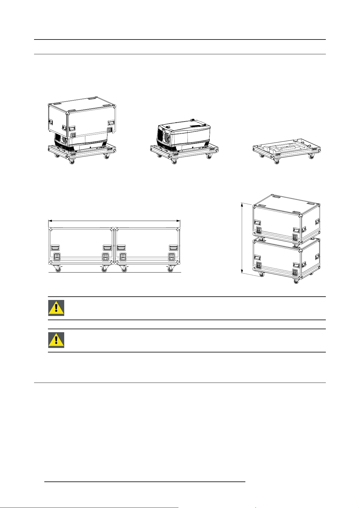
Introduction of the FLM flight case
The FLM flight case is designed to transport the FLM HD18 in a safe and secure manner. The four caster wheels, provided with
breaks, and the eight handles make the FLM flight case easy to handle. The fl oor of the flight case wagon is equipped with two
small covered compartments to store the remote control and the rigging clamps. Furthermore, three Velcro strips are attached to
the bottom for fastening the power cord of the projector.
Image 2-4
FLM flight case (R9854510).
The dimensions of the FLM flight case are optimal for maximum utilization of the floor area of a truck. The cover of the FLM flight
case has four stacking dishes, which allows to stack the flight cases.
2400 mm
m
m
0
0
6
1
Image 2-5
WARNING: Maximum stack two (2) FLM flight cases high. Never higher.
CAUTION: Prior to inserting project
or in fl ight case turn in the adjustable feet and interlocking adapters fully.
2.5 Projector configurations
The different configurations
Depending on the installation the projector can be mounted in different ways, the 4 different configurations are:
1. Front / Table (F/T)
2. Front / Ceiling (F/C)
3. Rear / Table (R/T)
4. Rear / Ceiling (R/C)
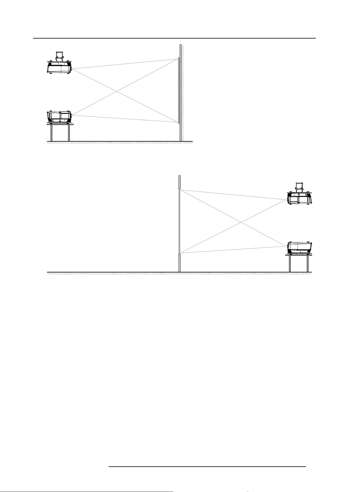
Front projection
The projector is installed, either in a table mount or ceiling mount configuration, at the same side of the screen as the audience.
12
R5976986 FLM HD18 15/03/2010
Page 17
F/C
2. General
AUDIENCE
F/T
FLOOR
Image 2-6
SCREEN
Rear projection
The projector is installed, either in a table mount or ceiling mount configuration, at th
AUDIENCE BACKSTAGE
N
E
E
R
C
S
FLOOR
Image 2-7
e other side of the screen opposite the audience.
R/C
R/T
R5976986 FLM HD18 15/03/2010 13
Page 18
2. General
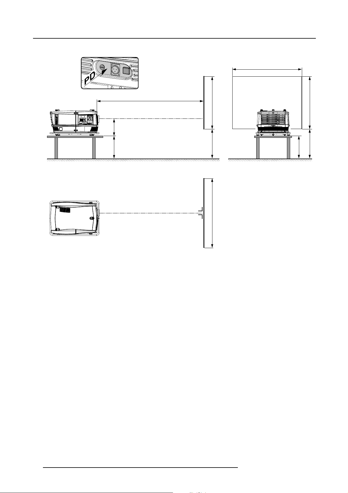
Positioning the projector
SW
PD
ACD
SCREENSCREEN
SHB
SCREEN
SHB
CD
FLOOR
SW
Image 2-8
The projector should be installed at right angles (horizontally and vertically) to the screen at a distance PD. Note the distance (A)
between lens centre and table surface is slight
and the vertical lens shift is set to zero (0).
ly variable. This distance (A) is nominal 35 cm in case all feet are turned in completely
On-Axis / Off-Axis projection
The position of the projector with reference to the screen may also be different depending on the installation. Basically the projector
can be positioned in On-Axis or Off-Axis configuration. On-Axis configuration means that the projector is positioned so as to have
the centre of the lens coinciding with the centre of the screen. Off-Axis projection is obtained by shifting the lens up, down, left or
right. Several parameters can be calculated determining the position in any installation.
Formula to calculate the distance CD for On-Axis projection: CD=SH/2+B-A
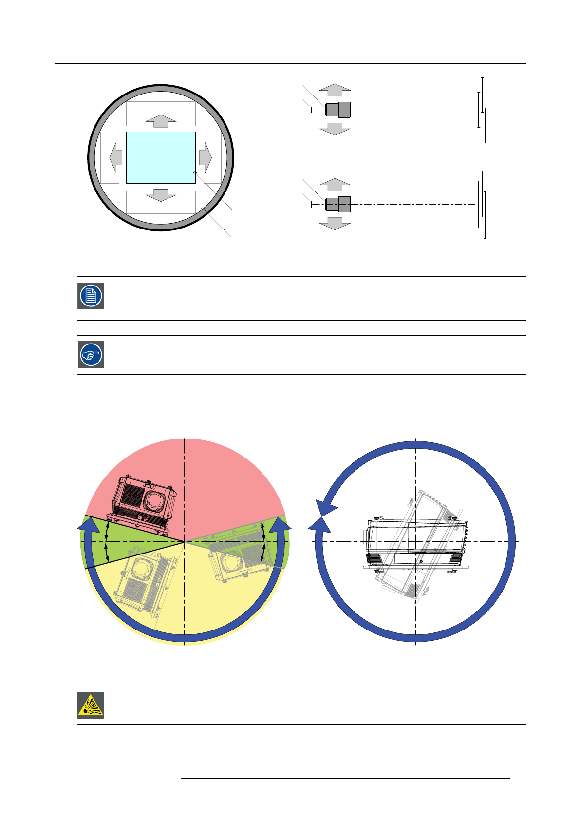
Shift range
The lens can be shifted with respect to the DMD (P) which result in a shifted image on the screen (Off-Axis). A 100% shift means that
the centre point of the projected image is shifted by half the screen size. In other words, the centre point of the projected image falls
together with the outline of the image in an On-Axis projection. Due to mechanical and optical limitations it’s recommended to keep
the shift values within the field of view (F) as illustrated below. Within these shift ranges the projector and lens perform excellently.
Configuring the projector outside these shift ranges will result in a slight decline of image quality.
14
R5976986 FLM HD18 15/03/2010
Page 19
2. General
U
-52% +52%
L R
D
Image 2-9
PDMD.
F Field of view.
It’s mechanical possible to shift outside the recommended field of view (±120% UP/DOWN and ±70%
LEFT/RIGHT), but this will result in a slightly decline of image quality depending on the used lens and the
zoom position of the used lens. Furthermore, shifting too much in both directions will result in a blurred
image corner.
Best image quality is projected in the On-Axis configuration.
+110%
-110%
F
P
F
P
P
F
U
D
L
R
SIDE VIEW
TOP VIEW
+110%
-110%
-52%
+52%
Horizontal and vertical projector tilt ranges
The projector can be rotated and mounted at any vertical angle. In other words, you can tilt the lens side of the projector as much
as desired for your application. Side to side tile, however, must not exceed ±15°. This limit ensures that the lamp in the projector
operates properly and safely. More tilting within area C is allowed but lamp flicker can happen.
B
MAX
15°
15°
A
A
15°
15°
MAX
360°
C
Image 2-10
A Tilting allowed without prob lems
B No tilting allowed in this area
C Tilting allowed but lamp flicker possible
CAUTION: Always respect the allowed tilt range of the projector. Neglecting this will result in lamp flicker,
which reduces the light output and the life span of the lamp substantially. Furthermore, in the long term, the
possibility exist that the lamp explodes.
R5976986 FLM HD18 15/03/2010 15
Page 20
2. General
2.6 Projector air inlets and outlets
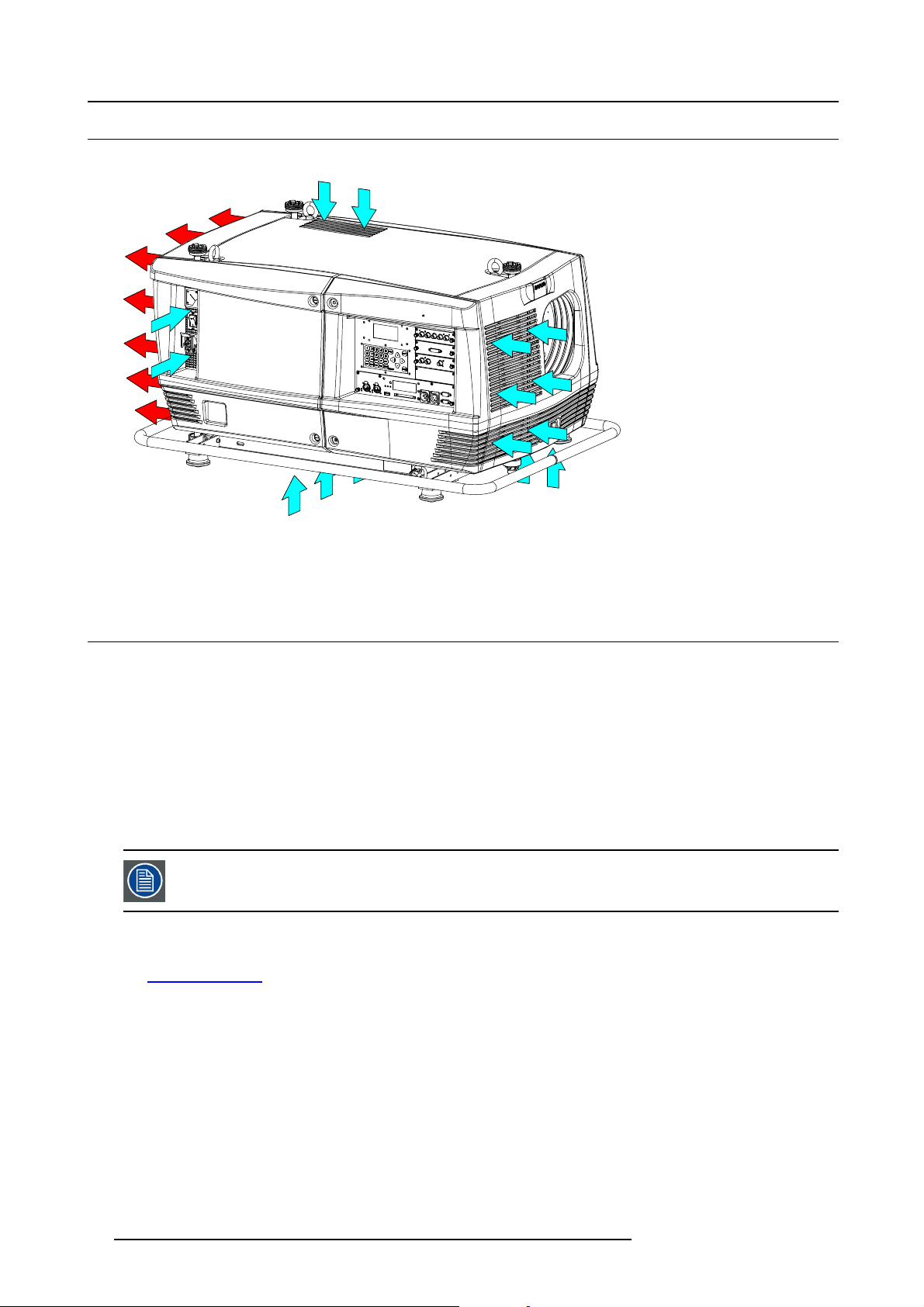
Air inlets and outlets
Image 2-11
The FLM HD18 has 5 air inlet channels and one air outlet. The air outlet is located at the rear of the projector. The air inlets are
located at the front, bottom, top and right side of the pr
ojector.
2.7 Free download of Projector Toolset
About Projector Toolset
Projector Toolset is a software tool to set up, configure, manage and control Barco projectors.
The concept of this Projector Toolset software is mod
modules, now and in the future available.
The Projector Toolset software works with configurations that can be loaded. Within a confi guration, different snapshots can be
taken. A snapshot represents a current state of a configuration and can be reloaded to return to this typical state. These terms will
be used through the complete software.
Projector Toolset is a stand-alone application that runs on a Java Virtual Machine and that does not require extra services to run.
Several configurations can be controlled simultaneously. Even when the configurations are connected via different ways.
Projector Toolset is only available in a download version, no CD can be ordered.
Where to find the download file(s)
The program and all necessary plug-ins, as well as the Reference manual can be downloaded for free from Barco’s Partnerzone,
URLh
ttps:\\my.barco.com. Registration is necessary.
If you are not yet registered, click on Partnerzone registration and follow the instructions. With the created login and password, it is
possible to enter the partnerzone where you can download the Projector Toolset software and the device plug-in updates as well as
the corresponding reference manual.
When downloading the complete Projector Toolset, this software contains already the latest device plug-ins. When you already have
the latest core version of Projector Toolset, it is possible to download only device plug-in updates from the same web site location.
As Projector Toolset is a stand alone application, it is not necessary to install any other software. A Java virtual machine is included
with this download.
ular. The basic package can be extended with several optional device plug-in
Installation
Download first the reference manual (Part number: R59770052) and follow the installation instructions as written in this manual.
16
R5976986 FLM HD18 15/03/2010
Page 21
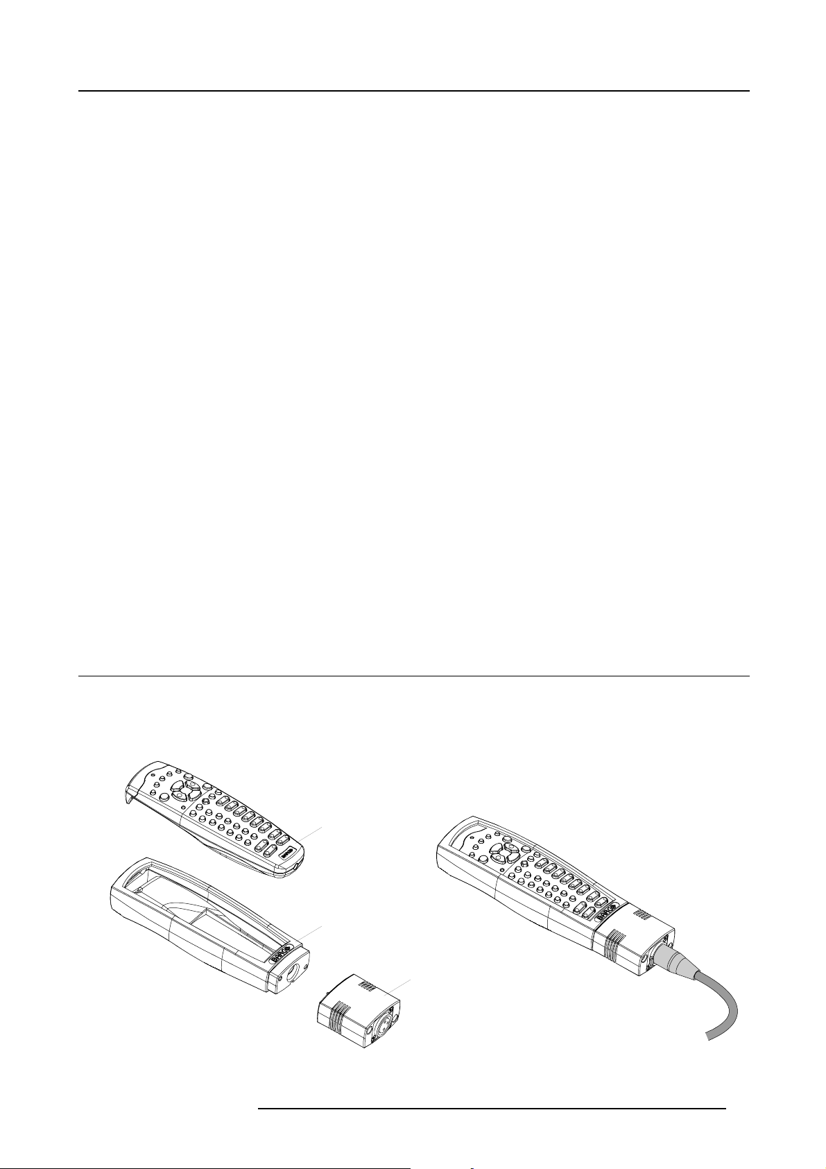
3. Physical installation
3. PHYSICAL INSTALLATION
About this chapter
This chapter explains how to install and set up your FLM projector. If you are familiar with the projector and want to quickly set it
up for temporary use, follow the “Quick setup” instructions below. For a more complete setup, follow the instructions and guides
covered in the remaining subsections.
Quick setup
The following steps describe briefly how to setup your FLM projector in a table mount front projection. Note that each step refers to
a corresponding procedure, which is more detailed and illustrated.
1. Install the batteries of the remote control, see "RCU battery installation", page 18.
2. Place the projector on a solid table in front of the screen at the expected throw distance. Ensure that the projector is installed
at right angles (horizontally and vertically) with the screen.
3. Select and install an appropriate lens, which covers the throw ratio ( = screen size / projector screen distance). For more details
see "Lens selection", page 22, and "Lens installation", page 23.
4. Connect the projector with the local power net, see "Power connection", page 35.
5. Connect your source to the appropriate input module, see "Input source connections", page 37.
6. Switch ON the projector, see procedure"Switching on", page 45.
7. Select the input slot at which your source is connected with. Do this by pressing the numeric key “1”, “2”, “3” or “4” on the
remote control unit or on the local keypad, see chapter "Source selection", page 53.
8. Zoom and shift the lens until the image is properly projected on the screen, Do this by using the “ZOOM” and “FOCUS” key on
the remote control unit or on the local keypad, see"Quick Lens Adjustment via LENS key", page 49 or "Direct Lens Adjustment
(RCU)", page 50. If necessary, level the projector from side to side by turning the adjustable feet in or out, see "Alignment of a
table mount FLM projector", page 25.
Overview
• Remote control unit (RCU)
• Lenses
• Alignment of a table mount FLM projector
• Alignment of a ceiling mount FLM projector
• Suspension of the FLM projector with rigging clamps
3.1 Remote control unit (RCU)
Introduction
The remote control unit (A) of the FLM projector is equipped w
unit can be used wired via mini-jack or via rugged XLR. Note that the backlight, of the remote control unit, illuminate continuously
when wire connected.
A
ith a rugged case (B) and an XLR adaptor (C). The remote control
B
C
Image 3-1
A Remote control unit (RCU).
B Rugged case.
R5976986 FLM HD18 15/03/2010 17
Page 22
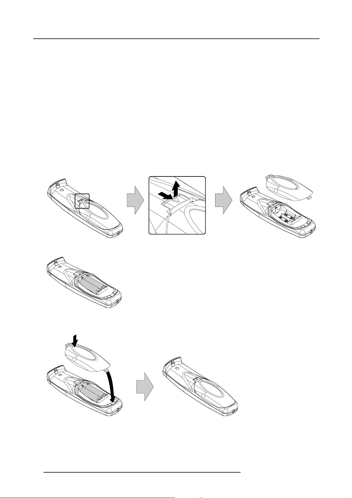
3. Physical installation
C XLR adaptor.
Overview
• RCU battery installation
• RCU rugged case installation
• RCU XLR adaptor installation
• Using the XLR adaptor of the RCU
• RCU usage possibilities
3.1.1 RCU battery installation
Where to find the batteries for the remote control ?
The batteries are not placed in the remote control unit to avoid control operation in its package, resulting in a shorter battery life
time. At delivery the batteries can be found in a separated bag attached to the remote control unit. Before using your remote control,
install the batteries first.
How to install the batteries in the remote control ?
1. Push the battery cover tab with the fingernail a little backwards (1) and pull, at the same time, the cover upwards (2).
1
Image 3-2
2. Insert the two AA size batteries, making sure the polarities match the + and - marks inside the battery compartment.
+
-
Image 3-3
3. Insert (1) the lower tab of the battery cover in the g
in place.
+
-
ap at the bottom of the remote control, and press (2) the cover until it clicks
2
2
1
-
Image 3-4
+
+
To prevent battery explosion
• Danger of explosion if battery is incorrectly installed.
• Replace only with the same or equivalent type recommended by the manufacturer.
• Disposal of used batteries must be done according to the manufacturer’s instruction.
18
R5976986 FLM HD18 15/03/2010
Page 23
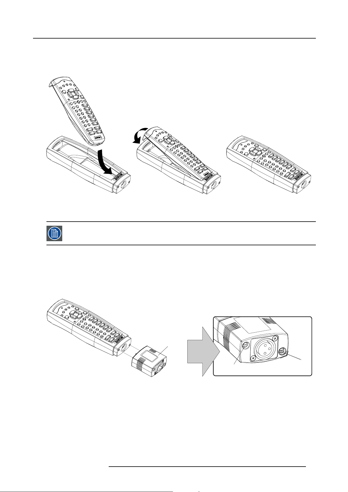
3. Physical installation
3.1.2 RCU rugged case installation
How to install the rugged case of the remote control ?
1. Slide the bottom of the RCU into the rugged case and then pull the top of the rugged case over the top of the RCU as illustrated.
Image 3-5
3.1.3 RCU XLR adaptor installation
Install the rugged case before installing the XLR adaptor. Vice-versa, remove the XLR adaptor before removing
the rugged case from the RCU.
Necessary tools
5mmflat screw driver.
How to install the XLR adaptor of the remote control unit ?
1. Push the XLR adaptor (C) upon the rugged case of the remote control unit as illustrated.
Note: Ensure that the text of the XLR adaptor is on top.
C
S
Image 3-6
2. Fasten the two screws (S) of the XLR adaptor. Turn each screw repeatedly one or two turns until both screws are tight.
S
3.1.4 Using the XLR adaptor of the RCU
How to use the XLR adaptor of the remote control unit ?
1. Connect a cable with XLR plug into the XLR adaptor.
2. Connect the other end of the cable with your FLM HD18.
3. Push the XLR adaptor completely against the rugged case of the remote control unit, as illustrated in the left image below, for
wired communication. Pull out the XLR adaptor (about 8 mm) to switch over to wireless communication.
R5976986 FLM HD18 15/03/2010
19
Page 24
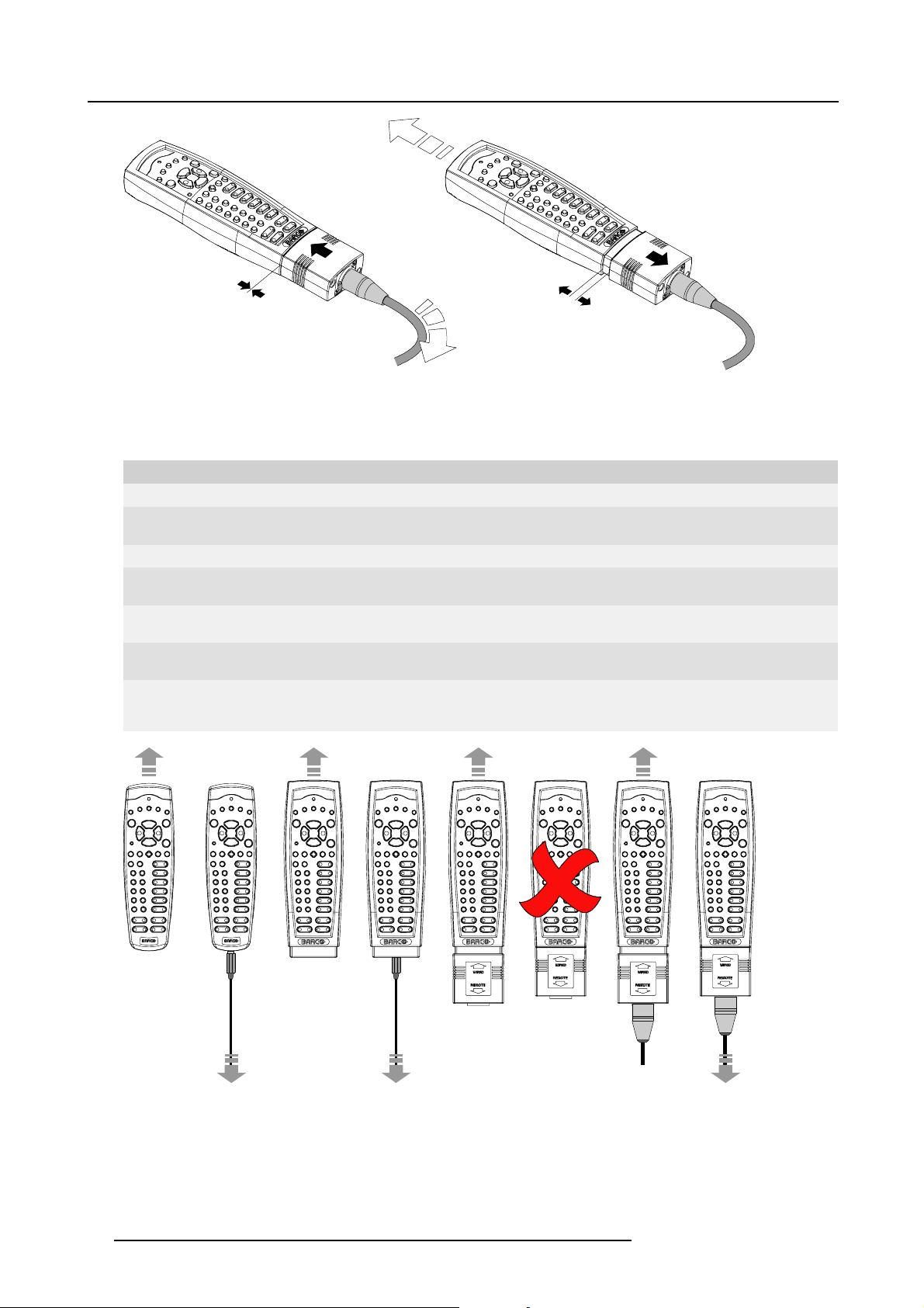
3. Physical installation
Image 3-7
3.1.5 RCU usage possibilities
Summarized possibilities
Ref. Possibility description Comment
a.
RCU not wired
b. RCU wired (mini-jack) Backlight illuminates continuously when wire is connected. Infra red
c.
RCU with rugged case not wired
d.
RCU with rugged case wired (mini-jack) Backlight illuminates continuously when wire is connected. Infra red
e.
RCU with rugged case and XLR adaptor
pulled out “REMOTE” and not wired
f. RCU with rugged case and XLR adaptor
pulled out “REMOTE” and wired
g.
RCU with rugged case and XLR adaptor
pushed in “WIRED” and wired
disabled.
disabled.
The XLR adaptor must be in the pulled out position “REMOTE”, otherwise
the RCU will not function.
The RCU will send the commands via infra red to the projector.
The RCU will send the commands via the cable connected with the XLR
adaptor to the projector. Backlight illuminates continuously when wire
is connected. Infra red disabled.
abcd fge
Image 3-8
20 R5976986 FLM HD18 15/03/2010
Page 25
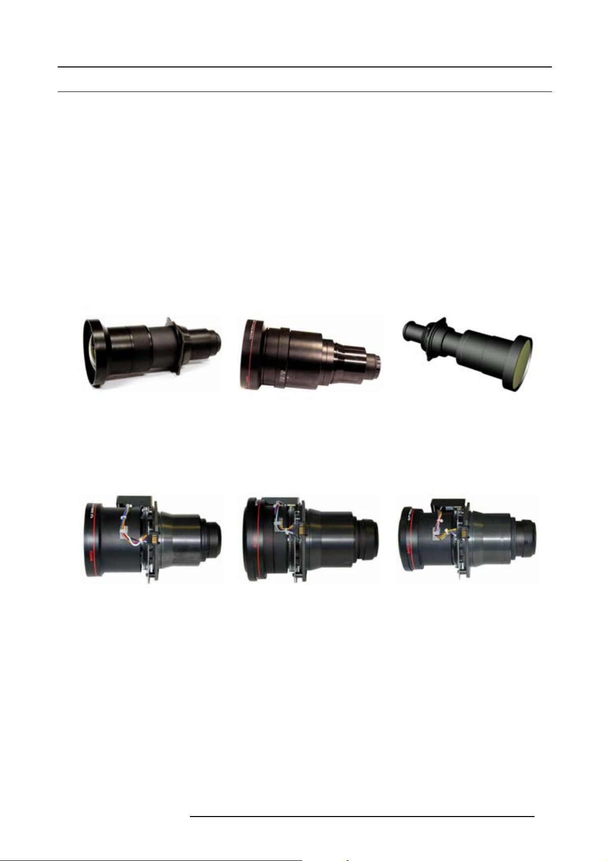
3. Physical installation
3.2 Lenses
Overview
• Available lenses
• Lens selection
• Lens formulas
• Lens installation
• Lens removal
3.2.1 Available lenses
Available lenses for the FLM HD18 projector
The TLD and the TLD HB (High Brightness) lens series can be used on the FLM HD18 projector. Note that there is no physical
difference on the outside between the TLD and the TLD HB lenses with corresponding focal length. The TLD HB lenses are recommended on the FLM HD18 projector. Note that the classical TLD lenses have approximately 20% less light output compared to the
TLD HB lenses, but 25% more contrast.
Image 3-9
R9840900:TLDfixedlens(0.8: 1);
R9842040:TLDHBfixedlens(0.8:1)
Image 3-12
R9840670: TLD zoom lens (1. 6 - 2.0 : 1) ; R9842060:
TLD HB zoom lens (1.6 - 2.0 : 1)
Image 3-10
R9840770:TLDfixedlens(1.2: 1)
Image 3-13
R9840680: TLD zoom lens (2.0 - 2.8 : 1 ) ; R9842080:
TLD HB zoom lens (2.0 - 2.8 : 1)
Image 3-11
R9840775: TLD+ (1.2 : 1) fixed lens
Image 3-14
R9840690: TLD zoom lens (2.8 - 5.0 : 1 ) ; R9842100:
TLD HB zoom lens (2.8 - 5.0 : 1)
R5976986 FLM HD18 15/03/2010 21
Page 26
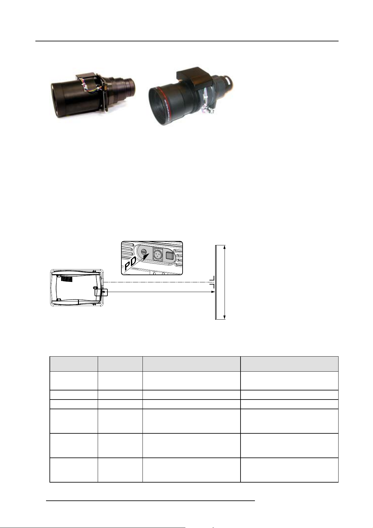
3. Physical installation
Image 3-15
R9840910: TLD zoom lens (5. 0 - 8.0 : 1) ; R9842120:
TLD HB zoom lens (5.0 - 8.0 : 1)
Image 3-16
R9829997: TLD+ zoom lens (7.5 - 11.2 : 1)
3.2.2 Lens selection
How to select the right lens for your application ?
1. Determine the required screen width (SW).
2. Determine the position of the projector in the projection room with regard to the screen and measure the projector-screen distance
(PD).
3. Use the lens formulas to find the best corresponding PD with regard to the measured projector-screen distance for the required
screen width SW.
Tip: Divide PD by SW to determine the approximate throw ratio. Choose a Lens, which captures the calculated throw ratio.
Use the lens formula of the chosen Lens to recalculate exactly.
SCREEN
PD
Image 3-17
SW
3.2.3 Lens formulas
Formulas
Lens
TLD (0.8 : 1)
TLD HB (0.8 : 1)
TLD (1.2 : 1)
TLD+(1.2:1)
TLD (1.6 – 2.0 : 1)
TLDHB(1.6–2.0
:1)
TLD (2.0 – 2.8 : 1)
TLDHB(2.0–2.8
:1)
TLD (2.8 – 5.0 : 1)
TLDHB(2.8–5.0
:1)
22 R5976986 FLM HD18 15/03/2010
Throw ratio for
FLM HD
0.7
1.1
1.2
1.35 – 1.70
1.70 – 2.42
2.42 – 4.35
Metric formulas (meter) Inch formulas (inch)
PD = (0.71 x SW ) + 0.05 PD = (0.71 x SW ) + 1.97
PD = (1.03 x SW ) - 0.01 PD = (1.03 x SW ) - 0.39
PD= (1.14 x SW) + 0.11 PD = (1.14 x SW) + 4.33
PD
= (1.36 x SW ) - 0.09
min
= (1.71 x SW ) - 0.13
PD
max
PD
= (1.71 x SW ) - 0.17
min
= (2.42 x SW ) - 0.24
PD
max
PD
= (2.38 x SW ) - 0.16
min
= (4.35 x SW ) - 0.38
PD
max
PD
= (1.36 x SW ) - 3.54
min
= (1.71 x SW ) - 5.12
PD
max
PD
= (1.71 x SW ) - 6.69
min
= (2.42 x SW ) - 9.45
PD
max
PD
= (2.38 x SW ) - 6.30
min
= (4.35 x SW ) - 14.96
PD
max
Page 27
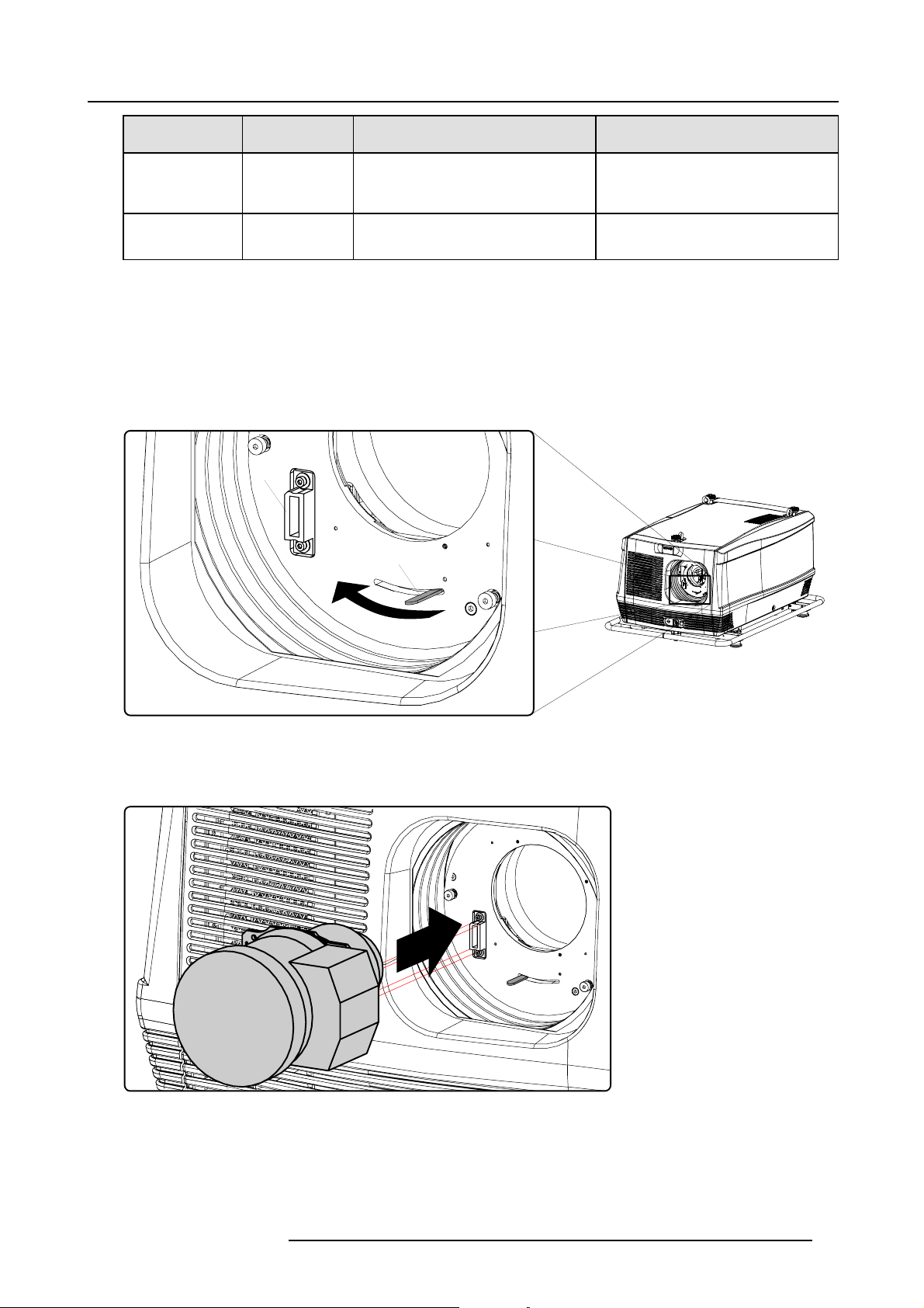
3. Physical installation
Lens
Throw ratio for
Metric formulas (meter) Inch formulas (inch)
FLM HD
TLD (5.0 – 8.0 : 1)
TLDHB(5.0–8.0
4.35 – 6.95
PD
PD
:1)
TLD+(7.5 – 11.2 :1)6.93 - 10.34 PD
PD
= (4.17 x SW ) - 0.01
min
= (6.95 x SW ) - 0.29
max
= (6.93 x SW ) - 0.2
min
= (10.34 x SW ) - 0.32
max
PD
= (4.17 x SW ) - 0.39
min
= (6.95 x SW ) - 11.42
PD
max
PD
= (6.93 x SW ) - 7.88
min
= (10.34 x SW ) - 12.60
PD
max
3.2.4 Lens installation
How to install a lens into the projector lens holder ?
1. Remove the foam rubber in the opening of the lens holder if not removed yet.
2. Take the lens assembly out of its packing material and remove the lens caps on both sides.
3. Place the lens holder in the “unlocked” position by moving the lens lock handle (A) towards the lens power supply socket (B) as
illustrated.
B
A
Image 3-18
4. Ensure that the lens holder stands in the On-Axis position (horizontal and vertical mid position).
Note: The lens holder is placed default in the On-Axis position a
tfactory.
5. Gently insert the lens in such a way that the lens connector matches the socket (B).
Image 3-19
6. Insert the lens until the connector seats into the socket.
Warning: Do not release the Lens yet, as the Lens may fall out of the Lens Holder.
7. Secure the lens in the lens holder by sliding the lens lock handle into the “locked” position, which is away from the lens power
supply socket. Ensure the lens touches the front plate of the lens holder.
R5976986 FLM HD18 15/03/2010
23
Page 28
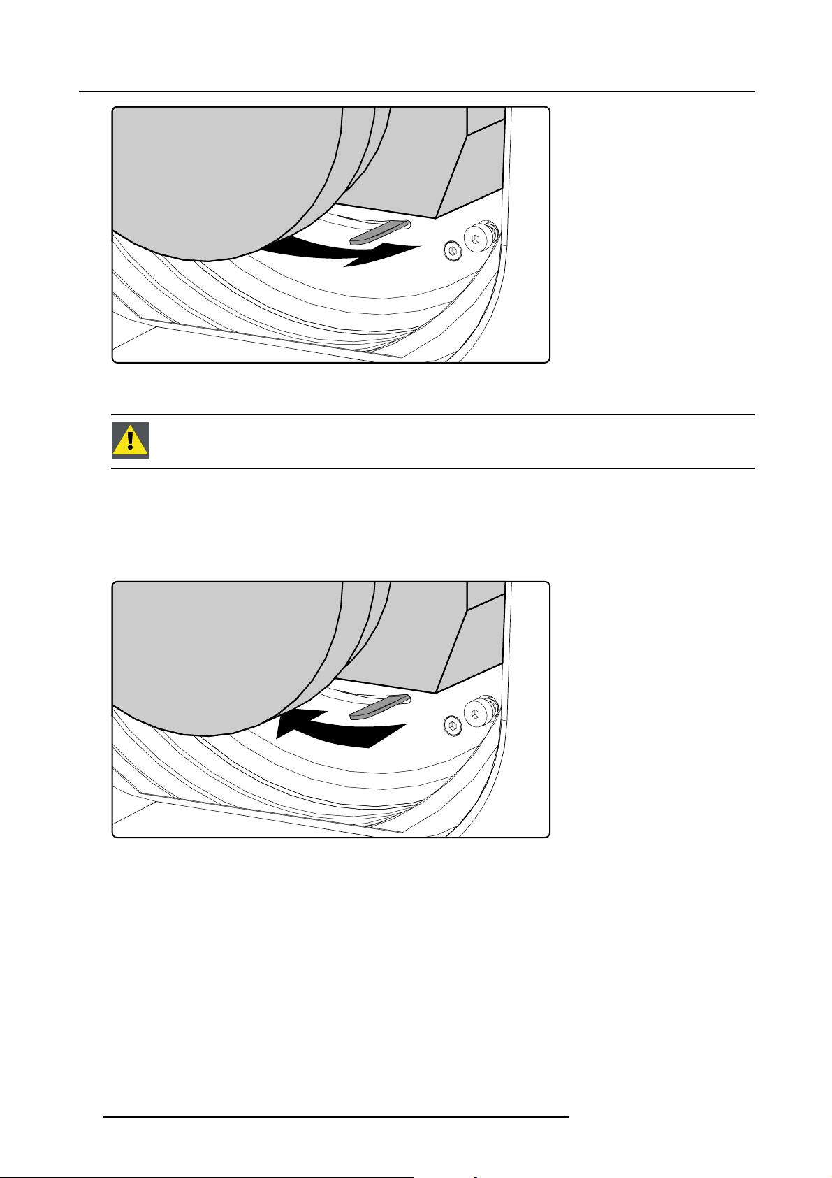
3. Physical installation
Image 3-20
8. Check if the lens is really secured by trying to pull the lens out of the lens holder.
CAUTION: Never transport the projector with a Lens mounted in the Lens Holder. Always remove the Lens
before transporting the projector. Neglecting this can damage the Lens Holder and Prism.
3.2.5 Lens removal
How to remove a lens from the projector lens holder ?
1. Support the lens with one hand while you unlock the lens holder by sliding the lock handle towards the “unlocked” position as
illustrated.
Image 3-21
2. Gently pull the lens out of the lens holder.
24
R5976986 FLM HD18 15/03/2010
Page 29
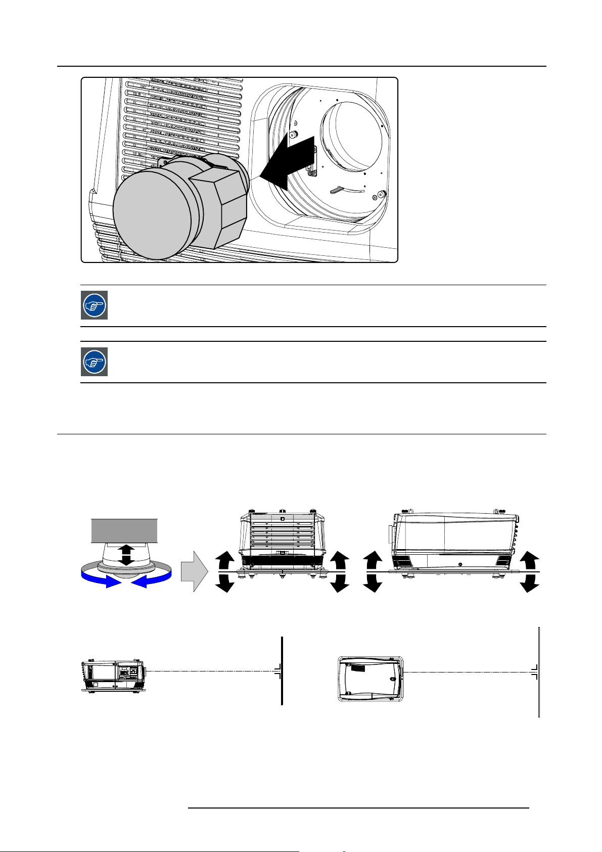
Image 3-22
3. Physical installation
It’s recommended to place the Lens caps of the original Lens packaging, back on both sides of the removed
Lens to protect the optics of the Lens.
It’s recommended to place the foam rubber of the original projector packaging, back in the Lens opening to
prevent intrusion of dust. Note that this foam rubber is packed in a plastic bag to prevent the dust, emitted by
the foam, from entering the projector.
3.3 Alignment of a table mount FLM projector
How to align a table mount FLM projector ?
1. Place the projector in the desired location. Take into account the zoom range of the used lens and the size of the screen.
2. Project one of the internal hatch patterns on the screen.
3. Turn the adjustable feet in or out until the projected hatch pattern is perfectly rectangle shaped and leveled.
Image 3-23
When this is achieved, the projector is set horizontal and vertical at right angles to the screen.
SCREEN
Image 3-24
SCREEN
R5976986 FLM HD18 15/03/2010 25
Page 30
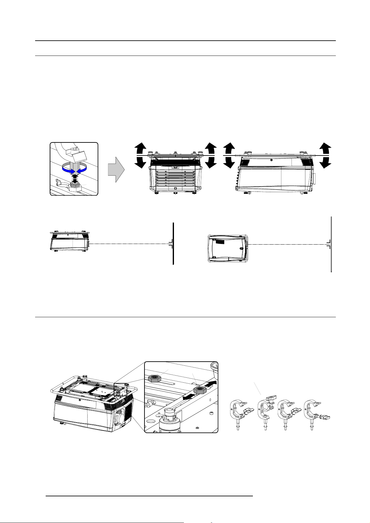
3. Physical installation
3.4 Alignment of a ceiling mount FLM projector
Necessary tools
17 mm open ended spanner.
How to align a ceiling mount FLM projector ?
1. Install the projector in the desired location. See installation procedure "Suspension of the FLM projector with rigging clamps",
page 26. Take into account the zoom range of the used lens and the size of the screen.
2. Project one of the internal hatch patterns on the screen.
3. Release the lock nut (ref B image 3-25) of the rigging clamps.
4. Adjust the height of the rigging clamps with respect to the projector, until the projected hatch pattern is perfectly rectangle shaped
and leveled.
B
Image 3-25
When this is achieved, the projector is set horizontal and vertical at right angles to the screen.
SCREEN
Image 3-26
5. Fasten the lock nut (B) of the rigging clamps.
3.5 Suspension of the FLM projector with rigging clamps
Rigging points and rigging clamps
The carrying handle, at the bottom side of the projector, is provided with eight slots. Four slots are longitudinally (A) oriented and
four slots are transversely (B) oriented. Each slot contains a rigging point of which the position in the slot can be adjusted depending
on the size of the truss installation. The rigging clamps (C) can be attached to those rigging points, which allows an easy and fast
physical setup of the projector in a hanging configuration.
A
B
C
SCREEN
Image 3-27
Necessary tools
• 24 mm open ended spanner.
• 17 mm open ended spanner.
26
R5976986 FLM HD18 15/03/2010
Page 31

3. Physical installation
Necessary parts
• Four rigging clamps (R820411).
• Safety chains.
How to install and to use the rigging clamps ?
1. Measure the distance, center tube as reference, between the two used support bars of the truss.
X mm
Image 3-28
2. Turn the projector upside down and slide the rigging points on there place in the slots, according the measured distance and
secure this position. To release the nuts of the rigging points use a 24 mm open ended spanner. Ensure that the rigging points
are symmetrically lined up, so that the projector will hang in balance.
Warning: Be careful while working with heavy loads.
Warning: Always secure the rigging points after adjustment.
X mm
N
Image 3-29
3. Turn in the rigging clamps (A) into the rigging points using a 17 mm open ended spanner and secure the rigging clamps by turning
the safety nut (B) on the rigging clamp against the rigging point using a 17 mm open ended spanner.
Warning: Always use four (4) rigging points, equally spread, to suspend the projector.
A
B
B
Image 3-30
4. Place all four rigging clamps in open position as illustrated.
R5976986 FLM HD18 15/03/2010
27
Page 32

3. Physical installation
Image 3-31
5. Place the projector (upside down) under the truss installation and lower the truss until the support bars of the truss are nearby
the rigging clamps mounted on the projector.
Image 3-32
6. Lift up the projector and hook the four rigging clamps over the support bars of the truss.
7. Lock all four rigging clamps.
8. Install a safety chain (S) around both sides of the carrying handle and around the truss.
S
Image 3-33
9. Lift up the truss with attached projector to the desired height.
S
28
R5976986 FLM HD18 15/03/2010
Page 33

3. Physical installation
Proceed with the alignment procedure, see "Alignment of a ceiling mount FLM projector", page 26.
R5976986 FLM HD18 15/03/2010 29
Page 34

3. Physical installation
30 R5976986 FLM HD18 15/03/2010
Page 35

4. Stacking FLM projectors
4. STACKING FLM PROJECTORS
General
Three interlocking adapters at the top and at the bottom of the FLM projector allows an easy and fast stacking without using extra
tools or accessories.
WARNING: Maximum stack three (3) FLM projectors in a table mount configuration.
Maximum stack two (2) FLM projectors in a ceiling mount configuration.
Overview
• Stacking FLM projectors
• Aligning stacked FLM projectors
4.1 Stacking FLM projectors
How to stack FLM projectors ?
1. Turn in the four feet of the projector you want to stack.
2. Place the projectors on top of each other. Ensure that all three interlocking pins (A) match with their corresponding interlocking
sockets (B).
Tip: In case of stacking projectors for a ceiling mount configuration, first turn the projectors upside down before placing the
projectors on top of each other.
A
B
Image 4-1
3. Attach the two projectors together by closing all three interlocking adapters as illustrated.
A B
C D
Image 4-2
R5976986 FLM HD18 15/03/2010 31
Page 36

4. Stacking FLM projectors
4. Are these projectors stacked for a ceiling mount configuration?
If yes, secure the projectors with safety chains as follows:
a) Release the safety hook (H) at both sides of the lowest projector and guide the safety cable around its carrying handle (C) as
illustrated.
Image 4-3
b) Guide the safety cable around the carrying handle of the projector above and clasp the safety hook around the safety cable
as illustrated.
C
H
Image 4-4
WARNING: Always use both safety cables of the lowest projector to secure a stacked projector in a ceiling
mount confi guration.
How to open an interlocking adapter ?
1. Open an interlocking adaptor as illustrated.
BA
D
C
Image 4-5
32 R5976986 FLM HD18 15/03/2010
Page 37

4. Stacking FLM projectors
WARNING: Never open an interlocking adapter of a stacked projector which is still suspended. First place
the stacked projectors on the floor.
4.2 Aligning stacked FLM projectors
Necessary tools
8mmAllenkey.
How to align two stacked FLM projectors ?
1. Make sure that the internal hatch pattern projected by the reference projector is sharp and has a perfect rectangle outline. If this
is not the case, readjust the reference projector before aligning the other stacked projector(s) with the reference hatch pattern.
Note: The reference projector in a stacked configuration is the lowest projector in case of table mount and the uppermost
projector in case of ceiling mount.
2. Project with the stacked projector the same internal hatch pattern as the reference projector.
Tip: Use a white colored hatch pattern for the reference projector and e.g. green colored for the stacked projector. This
makes it easier to see the difference between both hatch patterns projected.
3. If necessary, adjust the rotation of the stacked projector with respect to the reference projector by turning in or out the height
adjustment ring of the interlocking adaptors at the rear of the stacked projector. Adjust until the outline of the hatch pattern is
most symmetric with the reference hatch pattern.
Tip: You can increase leverage by using a screw driver in the holes of the adjustment ring
R
o
t
a
t
i
o
n
Image 4-6
4. If necessary, adjust the inclination of the stac
ring of the interlocking adaptor at the front of the stacked projector in or out. Adjust until the outline of the hatch pattern is most
symmetric with the reference hatch pattern.
ked projector with respect to the reference projector by turning the height adjustment
Inclination
Image 4-7
5. If necessary, adjust the skew of the stacked projector with respect to the reference projector by turning the screw Q in or out
using a 8 mm Allen key. The screw Q is located behind the cover of the lamp, just above the volt meter. Adjust until the outline
of the hatch pattern is most symmetric with the reference hatch pattern.
Note: See procedure "Removal of the lamp cover", page 193, to access the skew adjustment screw Q.
R5976986 FLM HD18 15/03/2010
33
Page 38

4. Stacking FLM projectors
Skew
Image 4-8
6. Shift the hatch pattern horizontally and vertically until the outline of the hatch pattern is
to the reference hatch pattern.
Note: Note that the “Shift” function is motorized, which means that you have to access the projector software, via the local
keypad or remote control unit, to operate the “Shift” function.
Shift
Q
most symmetrically placed with respect
Image 4-9
7. Zoom the hatch pattern in or out until the outline of the hatch pattern matches exactly the outline of the reference hatch pattern.
Note: Note that the “Zoom” function is motorized, which means that you have to access the projector software, via the local
keypad or remote control unit, to operate the “Zoom” function.
Zoom
Image 4-10
8. If necessary, repeat from step 2 until the hatch pattern of the stacked projector is perfectly aligned with the hatch pattern of the
reference projector.
In case of a triple stacked table mount projector configuration adjust and align first the bottommost projector
(reference), than the projector in the middle and finally the uppermost projector.
34 R5976986 FLM HD18 15/03/2010
Page 39

5. Connections
5. CONNECTIONS
About this chapter
This chapter describes more in detail the power (P), the input source (S) and the communication (C) connections of the FLM HD18.
P C S
Image 5-1
Overview
• Power connection
• Input source connections
• Communication connections
5.1 Power connection
CAUTION: Use only the power cord provided with the projector.
How to connect your projector with the local power net ?
1. Ensure that the power switch (S) stands in the “0” (OFF) position.
2. Connect the power cord (P) with the power input socket of the projector as illustrated below.
3. Secure the power plug by locking the plug holder clamp (H).
4. Connect the other end of the power cord with the local power net.
Caution: Ensure that the power net meets the power requirements of the projector, which are: 200-240 VAC, 50–60 Hz, 20
amps at 230 VAC.
R5976986 FLM HD18 15/03/2010
35
Page 40

5. Connections
The voltmeter (M) will immediately indicate the value of the mains voltage as soon as the projector is connected with the power
net.
M
P
S
1
H
2
Image 5-2
WARNING: Do not attempt operation if the AC supply and cord are not within the specified voltage and power
range.
CAUTION: Once the projector is switched to standby, the lamp cooling fans will continue to run for approx-
imately five minutes to ensure that the projector and lamp have sufficiently cooled, at which point the fans
will automatically decrease to standby. To avoid therma
unplug the power cord while the lamp cooling fans are running. Never unplug the power cord to power down
the projector, first switch off the power switch and then unplug the power cord.
Fuses
The projector is protected with an automatic circuit breaker of 35 A which is built in into the power switch.
Volt meter
After starting up the projector (lamp ignition) check if the value indicated by the volt meter is still within the specified power range of
the projector. Note that in case the power net drops significantly during start up, the lamp will fail the ignite. If this is the case, take
the necessary measures to reinforce the power net to the projector before starting up the projector again.
l stress that can lead to premature lamp failure, never
Spare power plug
The projector is delivered with a spare power plug. This spare power plug is attached behind the nameplate of the projector. Remove
the cover of the lamp fi rst to access this spare power plug, see "Removal of the lamp cover", page 193. Note that only qualified
technical personnel may install a new power plug.
N
PE
Image 5-3
Pin configuration power plug HAN Q4/2 + PE.
36 R5976986 FLM HD18 15/03/2010
21
43
L
HAN Q4/2 +
Page 41

5. Connections
5.2 Input source connections
General
The input and communication unit is equipped with four input slots, which accept any type of input module designed for the FLM
projector. The modularity of the input modules makes the FLM projector very flexible regarding input source connectivity. Note that
the slot numbering is done from top to bottom. So, the uppermost slot is slot number “1”, the second is slot number “2”... etc. All
input modules have two status LED’s. The green LED lights up if the input module is selected as the active input module. The yellow
LED lights up if the input module has detected valid input syncs.
1
2
3
4
Image 5-4
CAUTION: Always install a cover plate on an unused input slot. This to prevent dust intrusion into the pro-
jector.
Available input modules
G
Y
Image 5-5
5 Cable input (Multi purpose) (R9854430).
Image 5-8
DVI input (R9854460).
Image 5-6
5 Cable input (Multi purpose) (R9854435).
Image 5-9
HDCP DVI input (R9854465).
Image 5-7
HDSDI - SDI input (R9854450).
Image 5-10
Cover plate for unused input slot (R848607).
R5976986 FLM HD18 15/03/2010 37
Page 42

5. Connections
The FLM HD18 is standard equipped with one 5 cable input module, one HDSDI - SDI input module and one
DVI input module. Input slot number 4 (lowermost) is covered with a input cover plate.
For more information about the FLM input modules see chapter “Specifications”.
5.3 Communication connections
Communication interface
EDCBA
DIAGNOSTIC CODE IR RECEIVER
OK REC
PC CARD
REMOTE
CTRL IN
1 2
3
REMOTE
CTRL OUT
PUSH
2
3
1
RS232 / 422 OUT
RS232 / 422 IN
PORT 1
10/100 BASE-T
PORT 2
STBY / ON
WARNING IR
USB
F G H I J K L M N O
Image 5-11
A Warning LED.
B Projector status LED.
C Two digit LED display for diagnostic code.
D IR-receiver (side).
E RS232/422 loop through output port.
F Ethernet port 1.
G Ethernet port 2.
H USB port.
I IR signal received LED.
J IR signal acknowledged LED.
K PCMCIA card-bus (slot).
L Mini-jack input port for remote control.
M XLR input port for remote control.
N XLR output por t for remote control.
O RS232/422 input port.
Projector status
The projector “status” LED (B) lights up green while in operation. The same LED lights up red when the projector is switched to
standby.
Besides the projector status LED (B) the communication interface has also a “warning” LED (A) which blinks in case the projector
encounters an internal problem concerning fan speed, temperature, supply voltages, ... etc. These type of problems still allows
the projector to operate (the show can go on) but an action will be required within a short time period. More information about the
involved problem is given on the local LCD display of the projector.
A two character 7-segment display (C) shows, during normal operation, the selected input slot number. If an error has occurred then
an error code appears on this two digit LED display.
IR communication (RC5)
An IR receiver (
rear of the projector. When using the remote control unit (wired or wireless), the “IR REC” (I) and the “IR OK” (J) LED’s will light up
indicating an IR signal was received and recognized.
D) is mounted on the communication interface. Note that there is also an IR receiver mounted at the front and at the
Wired remote control
If desired the remote control unit can be wired and plugged in into the 3,5 mm mini jack socket (L) or, when using a rugged wire
with XLR plugs, plugged in into the male XLR port (M) on the communication interface. Besides the XLR input port a female XLR
connector (N) for wired RC5 output is provided. This connector creates a buffered RC5 signal, available for the next projector in
the daisy chain. Whenever the projector has no power, a passive loop through is created from the remote control input port to the
38
R5976986 FLM HD18 15/03/2010
Page 43

5. Connections
female XLR output port (N). So, the following projector in the daisy chain will still receive his RC5 code. Note that the RC5 in/out
signals are without carrier.
Mini jack plug
XLR – Remote CTRL in XLR – Remote CTRL out
Pin Description Pin Description Pin Description
SGND
T
RC5 in
R
n.c. or GND
A B C
Image 5-12
A Mini stereo jack plug.
• S : SLeeve (shield)
•R:Ring
•T:Tip
B Male XLR socket.
C Female XLR socket.
1
2
3 XLR present sense 3 XLR present sense
S R T
GND
RC5 in
1
GND
2
RC5 out
PUSH
1
2
3
2 1
3
RS232/422 serial communication
The communication interface of the FLM HD18 supports RS232 and RS422 serial communication. You can use the RS232/RS422
input port (O) to connect a local PC to your FLM projector. This way you can configure and control your FLM projector from your
local PC.
Do not forget to set the projector’s baud rate (default = 115200) to match that of the computer.
The communication interface has also an active RS232/RS422 loop through output port (E). Whenever the projector has no power, a
passive loop through is created from the RS232/RS422 input port (O) to the RS232/RS422 output port (E). So, the following projector
in the daisy chain will still receive his RS232/RS422 commands.
Advantages of using RS232/RS422 serial communication:
• easy adjustment of the projector via PC (or MAC).
• allow storage of multiple projector configurations and set ups.
• wide range of control possibilities.
• address range from 0 to 255.
• sending data to the projector (update).
• copying data from the projector (backup).
RS232/422 input port RS232/422 output port
Pin Description Pin Description
1 DCD : Data Carrier Detect 1 — (not connected) —
2 RXD- : Receive Data 2 RXD- : Receive Data
3 TXD- : Transmitted Data 3 TXD- : Transmitted Data
4 DTR : Data Terminal Ready [RS232]
TXD+ : Transmitted Data [RS422]
5
GND : Ground
6 DSR : Data Set Ready [RS232]
RXD+ : Received Data [RS422]
7
— (not connected) —
4 DTR : Data Terminal Ready [RS232]
TXD+ : Transmitted Data [RS422]
5
GND : Ground
6 DSR : Data Set Ready [RS232]
RXD+ : Received Data [RS422]
7
— (not connected) —
R5976986 FLM HD18 15/03/2010 39
Page 44

5. Connections
RS232/422 input port RS232/422 output port
Pin Description Pin Description
8
CTS : Clear To Send
9 RI:RingIndicator 9
A B
8
— (not connected) —
— (not connected) —
54321
9876
Image 5-13
A Pin numbering male DB–9 connector.
B Pin numbering female DB-9 connector.
12345
6789
RS232
An Electronic Industries Association (EIA) serial digital interface standard specifying the characteristics of the communication path between two devices using either D-SUB 9 pins or D-SUB 25 pins connectors. This standard is used for
relatively short-range communications and does not specify balanced control lines. RS-232 i
s a serial control standard
with a set number of conductors, data rate, word length and type of connector to be used. The standard specifies component connection standards with regard to computer interface. It is also called RS-232-C, which is the third version
of the RS-232 standard, and is functionally identical to the CCITT
V.24 standard. Logical ’0’ is > + 3V, Logical ’1’ is < -
3V. The range between -3V and +3V is the transition zone.
RS422
An EIA serial digital interface standard that specifies the electrical characteristics of balanced (differential) voltage,
digital interface circuits. This standard is usable over longer distances than RS-232. This signal governs the asynchronous transmission of computer data at speeds of up to 920,000 bits per second. It is also used as the serial port
standard for Macintosh computers. When the difference between the 2 lines is < - 0.2V that equals with a logical ’0’.
When the difference is > +0.2V that equals to a logical ’1’..
Ethernet network communication
The FLM projector can be connected to a LAN (local area network) using port 1 (F) or port 2 (G) on the communication interface.
Once connected to the LAN, users are capable of accessing the projector from any location, inside or outside (if allowed) their
company network using the FLM control software: Projector Toolset. This toolset locates the projector on the network in case there
is a DHCP server or the user can insert the correct IP-address of the projector to access the projector. Once accessed, it is possible
to check and manipulate all the projector settings. Remote diagnostics, control and monitoring of the projector can then become a
daily and very simple operation. The network connectivity permits to detect potential errors and consequently improve the time to
servicing.
As there is a need to daisy chain projectors when they are in Ethernet network, an Ethernet switch is build in. the incoming network
is hereby available for the internal PC and for the next device in the chain. In this way a ’star’ network interconnection can be avoid.
The switch used is a stand alone 10/100Mbit Ethernet switch. This assures no infl uence on the network speed. Whenever a slow
(10Mbit) device is connected the speed between the 100Mbit devices remains 100Mbit.
Both Ethernet ports (F & G) are equipped with a yellow and green a LED. The yellow LED lights up in case the port is connected
with a 100Mbit network. The green LED
blinks in case there is network activity.
Pin Description
1TXD+
2TXD-
3RXD+
4
5
6RXD-
40
The connectors used for both Ethernet ports (F & G) are of rugged Neutrik EtherCon RJ45 type, which is
compatible with standard RJ45 cable connector. Straight (most common) as well as cross linked network
cables can be used. The 2 ports are functionally identical. Both ports are connected via the projector hub
(Auto sensing enabled).
10/100 Base-T — RJ45 port
—
—
R5976986 FLM HD18 15/03/2010
Page 45

5. Connections
10/100 Base-T — RJ45 port
Pin Description
—
7
—
8
USB port
The communication interface is equipped with a master USB port, type “A” connector (H). This USB port will simplify the service
procedures for taking backup files from the projector without network connection. An USB-stick is plugged into the USB port and
files can be transferred from or to the projector using the local or remote control unit. Note that the USB-stick has to be FAT16
compatible.
Card bus connector (PCMCIA)
No cards supported yet.
R5976986 FLM HD18 15/03/2010
41
Page 46

5. Connections
42 R5976986 FLM HD18 15/03/2010
Page 47

6. Getting started
6. GETTING STARTED
About this chapter
This chapter describes the functions on the remote control and local keypad and gives an overview how to start up the projector. If
gives also a brief overview of the direct adjustment possible with these controls.
Overview
• RCU & Local keypad
• Terminology overview
• Operating the projector
• Using the RCU
• Quick setup adjustments
• Projector address
• Source selection
• Controlling the Projector
6.1 RCU & Local keypad
How controlling the projector ?
The projector can be controlled by the local keypad or by the remote control unit.
Location of the local keypad ?
The local keypad is located on the input side of the projector.
Remote control functions.
This remote control includes a battery powered infrared (IR) transmitter that allows the user to control the projector remotely. This
remote control is used for source selection, control, adaptation and set up.
Other functions of the remote control are :
• switching between stand by and operational mode.
• switching to "pause" (blanked picture, full power for immediate restarting)
• direct access to all connected sources.
6.2 Terminology overview
Overview
The following table gives an overview of the different functionality of the keys.
R5976986 FLM HD18 15/03/2010
43
Page 48

6. Getting started
1
2
3
MENU
L
EXIT
4
310 10
4
3
2
1
6
RGB
STBY
7
2
89
7
PATTERN
WINDOW
TEXT
PAUSE
1
5
MENU
0
PIP
LENS
RIGGING
AUTO
21
920166
5
8
19
EXIT
ENTER
17
5
TEXT
SHARPN
BRIGHTN
CONTR
LENS
SHIFT
LENS
SHIFT
ENTER
PHASE
TINT
COLOR
6
PAUSE
7
LENS
8
0
9
10
11
9
8
7
6
5
3
4
2
1
LENS
ZOOM
LENS
FOCUS
22
21
20
19
18
17
16
15
14
13
12
Image 6-1
Local keypad & remote control
Ind. Key name Description
1 Pattern key Direct access key to the internal pattern selection menu.
or when an on-screen menu was displayed, the pattern is displayed immediately.
2
RGB
Toggle key to enable and disable colors in the adjustment mode. Toggle between red,
green, blue and full RGB.
3 MENU Access key to the menu structure and key to quickly quit the adjustment menus.
4 Address key
(recessed key), to enter the address of the projector (between 0 and 9) in the remote
control. Press the recessed address key with a pencil, followed by pressing one digit
button between 0 and 9.
5
LENS
Direct access key to the lens adjustment menus. Toggling this key will change the
projected pattern.
6
PAUSE To stop projection for a short time, press ’PAUSE’. The image disappears but full power
is retained for immediate restarting. Shutter is closed.
7
STBY Standby function switch off the lamp and lamp electronics. The lamp cooling fans remain
active for about 5 minutes. The speed of the other fans is reduced.
8 Rigging Direct access key to layout selection. Rigging key + sequence number opens directly
the desired layout.
9 Auto image Direct access key to automatically project the correct image.
10 Digit buttons Direct input selection or menu short cuts or numeric entries
11 Lens zoom/focus Zoom and focus controls of the lens
12 Lens shift Shift control of the lens, to shift the lens up/down or left/right
13 Picture controls Use these buttons to obtain the desired picture level.
44 R5976986 FLM HD18 15/03/2010
Page 49

6. Getting started
Ind. Key name Description
14
PHASE Used to remove the horizontal instability of the image (usually for RGB source). It adjusts
15 FREEZE
16 TEXT Toggle key to activate or deactivate on screen text boxes while adjusting a setting.
17 ENTER
18
Cursor keys
19 EXIT Key to go one menu stage higher than the actual position when in the adjustment mode.
20
WINDOW Selection of the active window, also in PIP mode.
21 PIP
22
RC Operating indication Lights up when a button on the remote control is pressed. (This is a visual indicator to
Ta bl e 6- 1
the phase of the pixel sampling clock relative to the incoming signal.
To freeze the actual projected image. Freeze sign is displayed in the upper left corner (a
short press on the key).
When pressing for 5 sec, the projector goes into stand-by. The lamp cooling fans remain
active for about 5 minutes. The speed of the other fans is reduced.
When adjusting one of the image controls, e.g.during a meeting, the normally displayed
bar scale can be deactivated by pressing ’TEXT’ key first. To re-display the bar scale
on the screen, press ’TEXT’ key again. When TEXT is ’off’, no adjustment menu’s
will be displayed on the screen when entering the adjustment mode. All menus and
adjustments remain active on the local LCD panel.
Key to confirm an adjustment or selection in the adjustment mode.
To make menu selections when in the adjustment mode
Direct access key for picture in picture selection.
check the operation of the remote control)
6.3 Operating the projector
Overview
• Switching on
• Errors, warnings and messages during start up
• Switching to standby
• Switching off
6.3.1 Switching on
Howtoswitchon.
1. Press the power switch to switch on the projector.
Image 6-2
Switching on
- When ’0’ is visible, the projector is switched off.
- When ’1’ is visible, the projector is switched on.
The projector starts up in standby. The menus are accessible via the local LCD panel.
To display an image, the standby key must be pressed once.
R5976986 FLM HD18 15/03/2010
45
Page 50

6. Getting started
The actual input voltage is indicated on the voltmeter just above the power switch.
Starting image projection via the standby key.
1. Press Stand by key once on the local keypad or on the remote control.
L
4
RGB
STBY
1
6
2
7
PATTERN
PAUSE TEXT
3
89
WINDOW
PIP LENS
RIGGING
AUTO
5
MENU
0
A
Image 6-3
Stand by indication
A Stand by indication on local keypad
B Stand by indication on remote control
EXIT
ENTER
MENU
B
PAUSE
LENS
0
9
8
7
6
5
3
4
2
1
LENS
ZOOM
LENS
FOCUS
TEXT
PHASE
SHARPN
TINT
COLOR
BRIGHTN
CONTR
LENS
SHIFT
LENS
SHIFT
EXIT
ENTER
The projector status LED lights up.
The projector starts up on the last saved source.
Some lamp and runtime warnings can be displayed when an image is displayed after a start up.
6.3.2 Errors, warnings and messages during start up
Temperature error DMD
When the temperature of one of the DMD’s is too low or too high the projector is switched automatically to standby. An error code
will be displayed on the local LCD panel. For a list of possible error codes, see "Error codes", page 211.
6.3.3 Switching to standby
How to switch to standby?
1. Press Standby to switch the projector to standby.
A cool-down counter (after cooling) starts counting down for 5 minutes (only visible on the local LCD panel). During this period
the fans are still running.
A restart is possible during this period.
46
R5976986 FLM HD18 15/03/2010
Page 51

6. Getting started
Switching to Standby. When the projector is running and you want to go to standby, press the standby key
for 2 seconds. Do not press any longer on the standby key otherwise the projector will restart.
All custom settings are written to the internal backup device. A message ’Save data ...’ indicates this process.
Never switch off the projector while this message is displayed.
When pressing for at least 5 seconds on the Freeze button, the projector goes to standby without the risk
restart..
6.3.4 Switching off
How to switch off the projector?
1. Press first Standby.
2. Let cool down the projector until the fans decrease, at least 5 min.
3. Switch off the projector with the power switch.
CAUTION: Never switch off the projector while the message ’Save data ... ’ is displayed !
6.4 Using the RCU
Pointing to the reflective screen
1. Point the front of the RCU to the reflective screen surface.
of
IR Sensor ( C)
Screen (B)
Image 6-4
IR control via the reflective screen
A Remote control
B Screen
C Front IR-sensor
Hardwired Remote Input
1. Plug one end of the remote cable in the connector on the bottom of the RCU.
R5976986 FLM HD18 15/03/2010
5
F
R
I
T
TE
EX
EN
E
4
P
S
F
N
R
T
N
T
A
R
IN
T
A
X
R
E
LO
H
P
T
T
TE
H
S
C
N
H
N
CO
L
RIG
B
CO
LA
O
V
3
BA
F
2
F
E
S
U
6
8
2
P
A
LE
SS
EB
J
BA
1
0
F
D
TR
A
4
7
9
5
1
3
Remote Control (A)
47
Page 52

6. Getting started
5-cable input
Sel
Sync OK
H/S V/Cs
R/Pr G/Y/Video B/Pb
DVI input
Sel
Sync OK
RIGGING
WarningIR
Std/ON
USB
MENU
EXIT
ENTER
Diagnostic code IR receiver
PC Card
Input 1
Input 2 Lo op o utput
Remote
CTRL in
PUSH
2 1
3
HDSDI - SDI input
Sel
Sync OK
Remote
CTRL out
RS232/422 ou t
PUSH
2 1
RS232/422 i n
3
123
67890
RGB
PATTERNWINDOW
STBYPA USETEXT
10/100 Based-T
Port 1 Po rt 2
45
PIP LENS
AUTO
Image 6-5
2. Plug the other end in the small connector in the input panel of the projector labeled Remote CTRL in.
The Remote connection uses a standard two wire cable terminated on each end with a 3.5 mm male
(mono/stereo) phone jack.
This cable is not delivered but is available in most electronic or audio shops.
Hardwired to the XLR input
1. Plug one end of the remote cable in the connector on the bottom of the RCU
2. Plug the other end in the big connector in the input panel of the proje
ctor labelled Remote CTRL in.
Directly to one of the IR sensors
When using the wireless remote control, make sure you are within the effective operating distance (30m, 100ft in a straight line). The
remote control unit will not function properly if strong light strikes the sensor window or if there are obstacles between the remote
control unit and the projector IR sensor.
5-cable input
Sel
Sync OK
R/PrG/Y/VideoB/Pb H/S V/Cs
DVI input
Sel
Sync OK
HDSDI - SDI input
2345
1
MENU EXIT
Sel
Sync OK
Input 1Input 2 Loop output
ENTER
RIGGINGAUTO
Diagnostic c odeIR rec eive r
Remote
Remote
Std/ON
RS232/422 ou t
CTRL in
CTRL out
WarningIR
PUSH
PUSH
2 1
2 1
RS232/422 i n
PC Card
USB
3
3
45°
45°
F
3
F
2
F
4
1
F
F
5
A
D
J
E
I
X
T
E
T
N
R
E
P
A
U
E
S
T
X
E
T
P
HAS
E
9
0
S
HAR
P
N
7
8
N
T
T
I
6
5
C
L
O
R
O
3
4
H
N
B
T
I
R
G
1
2
N
R
C
T
O
T
E
L
E
B
R
B
A
L
N
A
E
C
B
S
A
S
V
O
L
45°
45°
F
3
2
F
F
4
F
1
F
5
A
D
J
I
T
E
X
E
T
N
R
E
U
P
S
A
E
T
E
X
T
P
HAS
E
S
H
9
0
AR
P
N
7
8
T
N
T
I
5
6
C
L
O
R
O
3
4
N
B
I
R
GH
T
1
2
C
N
O
R
T
T
E
L
R
E
B
B
L
A
N
A
E
C
B
S
A
S
V
L
O
Image 6-6
RCU to one of the IR sensors
67890
RGB
PATTERNWINDOWPIPL ENS
STBYPAUSETEXT
10/100 Based-T
Port 2
Port 1
45°
45°
F
3
F
2
F
4
F
1
F
5
A
D
J
E
X
I
T
E
T
N
R
E
P
A
U
E
S
X
T
T
E
P
HAS
E
S
H
9
0
AR
P
N
7
8
T
N
T
I
5
6
C
L
O
R
O
3
4
N
B
I
R
GH
T
1
2
C
N
O
R
T
T
E
R
B
L
E
B
L
A
N
A
E
C
B
S
A
S
V
L
O
48 R5976986 FLM HD18 15/03/2010
Page 53

6. Getting started
6.5 Quick setup adjustments
Overview
• Text boxes ON or OFF
• Quick Lens Adjustment
• Quick picture in picture
• Quick layout selection with Rigging key
• Quick language selection
6.5.1 Text boxes ON or OFF
Text toggle function
The on-screen text boxes can be switched OFF so that an adjustment during the operation of the projector are not visible on the
screen. The adjustment indication remains visible on the local LCD screen.
To toggle Text ON or OFF, press the TEXT key on the remote control or local keypad.
6.5.2 Quick Lens Adjustment
6.5.2.1 Quick Lens Adjustment via LENS key
Quick zoom/focus adjustment
1. Press the LENS key on the remote control or local keypad.
The zoom/focus menu will be displayed.
Image 6-7
2. Push the cursor key ▲ or ▼ to zoom and ◄ or ► to focus the image.
3. When finished, press EXIT key to return or ENTER to continue to the shift adjustment.
Press the LENS key to switch to another pattern. Different patterns are available.
Quick shift adjustment
1. Press the LENS key on the remote control or local keypad.
The zoom/focus menu will be displayed.
Image 6-8
2. Press ENTER.
R5976986 FLM HD18 15/03/2010
49
Page 54

6. Getting started
The shift menu will be displayed.
Image 6-9
3. Push the cursor key ▲ or ▼ to shift the image up or down and ◄ or ► to shift the image left or right.
4. When finished, press EXIT key to return or ENTER to continue to zoom/focus.
Press the LENS key to switch to another pattern. Different patterns are available.
6.5.2.2 Direct Lens Adjustment (RCU)
Lens adjustment buttons on the Remote Control
On the Remote Control four buttons with double action are provided, allowing direct alignment for lens ZOOM, FOCUS, HORIZONTALSHIFTandVERTICALSHIFT.
1. Press LENS ZOOM button [-] or [+] (A) for correct image size on the screen.
2
Image 6-10
Direct lens adjustment keys
AZoom
B Vertical shift
CFocus
D Horizontal shift
A
C
1
LENS
ZOOM
LENS
FOCUS
CONTR
LENS
SHIFT
LENS
SHIFT
B
D
2. Press LENS FOCUS button [-] or [+] (C) for an overall focus of the image.
3. Press ▲ LENS SHIFT ▼ button for correct vertical position of the image on the screen.
4. Press ◄ LENS SHIFT ► button for correct horizontal position of the image on the screen.
6.5.3 Quick picture in picture
Quick On - Off
Press on the PIP key on the remote control or the local keypad to activate the Load layout window.
Use the ▲▼key to scroll to the desired layout and press ENTER to activate.
Select Main full screen to switch off PIP.
50 R5976986 FLM HD18 15/03/2010
Page 55

6. Getting started
Image 6-11
6.5.4 Quick layout selection with Rigging key
What can be done ?
When the projector is playing, changing from one layout to another is possible without displaying any on screen selection menu.
The current image is not disturbed as long no selection is made. Press the Rigging key followed by one or two digits to jump to a
new layout.
When Rigging is pressed, an overview of the possible layouts with a sequence number is given on the local LCD panel. That
sequence number is the number that should be pressed after Rigging is pressed to change the layout to the new selection.
How to make a selection
1. Press Rigging followed by one or two digits and wait.
Note: If you press only one digit, the projector wait a few time to check if a second digit will follow. If not, it switches to the
selected layout.
The selected layout is loaded.
Or,
press Rigging.
The layout selection menu is displayed on the local LCD panel.
Image 6-12
2. Enter the digit or the two digits of your choice.
The selected layout is loaded.
Or,
scroll with the arrow keys to the desired layout and press ENTER.
The selected layout is loaded.
When no digit is pressed after Rigging is pressed, the layout selection menu disappears after a few seconds
without a layout change.
6.5.5 Quick language selection
Language selection
1. Press Menu to activate the menus and select with the ▲ or ▼ key Projector Control and press ENTER.
2. Select with the ▲ or ▼ key Language and pre
The language menu opens.
3. Select with the ▲ or ▼ key the desired language and press ENTER to activate.
R5976986 FLM HD18 15/03/2010
ss ENTER.
51
Page 56

6. Getting started
The current active language is indicated with an asterisk (*).
Image 6-15
Image 6-13
Image 6-14
6.6 Projector address
6.6.1 Displaying and Programming addresses
Displaying the Projector Address on the Screen.
1. Press Address key (recessed key on the RCU) with a pencil.
The projector’s address is displayed as first item in the Identification screen.
Image 6-16
To continue using the RCU with that specific address, it is necessary to enter the same address with the
digit buttons (address between 0 and 9) within 5 seconds after pushing the address key. For example : if the
Address key displays projector address 003, then press "3" digit button on the RCU to set the RCU’s address
to match the projector’s address. Do not press 003 digits. This will address the remote control to ’0’ and
control all projectors in the room. If the address is not entered within 5 seconds, the RCU returns to its default
address (zero address) and control all projectors in the room.
How to Program an Address into the RCU?
1. Press the Address key (recessed key on the RCU) with a pencil.
2. Enter the address with the digit buttons within 5 seconds after pushing the address key.
Note: That address can be any digit between 0 and 9.
The LED on the remote control must lit up while pressing a digit key. Otherwise the address is not entered in
the remote control.
52 R5976986 FLM HD18 15/03/2010
Page 57

6. Getting started
6.6.2 Controlling the projector
Projector address
Address installed in the projector to be individually controlled.
Common address
Projector will always execute the command coming from a RCU programmed with that common address.
Why a projector address ?
As more than one projector can be installed in a room, each projector should be separately addressable with an RCU or computer.
Therefore each projector has its own address.
Set up an individual Projector Address.
The set up of a projector address can be done via the software. See chapter ’Projector Control’, ’Projector address’.
Projector controlling.
Every projector requires an individual address between 0 and 255 which can be set in the Service mode.
When the address is set, the projector can be controlled now:
• RCU for addresses between 0 and 9.
• computer, e.g. IBM PC (or compatible), Apple MAC, etc. for addresses between 0 and 255.
Common Address
Every projector has a common address ’0’ or ’1’. The choice between ’0’ and ’1’ can be select
address → Common address.
ed in Projector Control → Projector
6.7 Source selection
Source selection when no picture in picture is active
Use the digit keys on the remote control or local keypad to active the desired source.
Source selection when picture in picture is active
Use the Window button on the remote control or the local keypad to select the main window or the picture in picture (PiP) window.
4
AUTO
5
MENU
0
PIP
LENS
RIGGING
EXIT
ENTER
MENU
PAUSE
L
EXIT
ENTER
TEXT
LENS
1
6
RGB
STBY
3
2
89
7
PATTERN W INDOW
PAUSE TEXT
PHASE
Image 6-17
Window selection button
The outline of the selected window gets a colored rectangle to indicate the selection. For the main window, the color is blue. For the
picture in picture window, the color is orange.
Once the desired window is activated (main window or picture in picture window) all keys on the remote control or local keypad can
now control that selected window.
To select the source for the picture in picture window, press Window button until PiP window is activated and then select the desired
source with the digit keys.
To select the source for the main window, press Window button until the main window is activated and then select the desired source
with the digit keys.
R5976986 FLM HD18 15/03/2010
53
Page 58

6. Getting started
6.8 Controlling the Projector
Picture Controls
When an image control is pressed, a text box with a bar scale, icon and function name of the control, e.g. ’brightness...’ appears on
the screen (only if text is ON). See example screen. The length of the bar scale and the value of the numeric indication indicate the
current memorized setting for this source. The bar scale changes as the control buttons on the RCU are pressed.
Brightness
Contrast A correct ’contrast’ setting is important for good image reproduction. Adjust the contrast to the level
Color Color saturation is only active for all type of video sources, such as Video, S-Video, SDI, HDSDI.
Tint
Sharpness The sharpness function is used to adjust the image sharpness of video signals.
Phase
A correct ’brightness’ setting is important for good image reproduction.
Use the + button for a higher brightness.
Use the - button for a lower brightness.
you prefer, according to room lighting conditions.
Use the + button for a higher contrast.
Use the - button for lower contrast.
Adjust the color intensity of the picture.
Use the + button for richer colors.
Use the - button for lighter colors.
Tint is only active for Video and S-Video when using the NTSC 4.43 or NTSC 3.58 system.
Use the + button for more tint
Use the - button for less tint.
Use the + button for more sharpness
Use the - button for less sharpness
Use the + or - side of the phase control button to adjust the phase.
The Pause Key
When the Pause key is pressed, the image projection is stopped, a black screen will be displayed and the projector remains with full
power for immediate restart. The 7-segment display on the projector will show a "P". The shutter is closed.
To restart the image, press one of the following keys:
•PressPause key.
• Select a source number.
The Stand-by Key
When the Stand-by key is pressed, the image projection is stopped and the projector goes to stand-by. This situation is used when
a projection stop is planned for a longer period. All custom settings are saved to an internal backup device. A message ’Save data
...’ is displayed during this backup operation.
The Freeze key
When pressing for 5 seconds on the Freeze button, the projector goes to stand-by. This function is very useful when multiple projectors have to be switched to stand-by. Set the RCU address to the common address and press Freeze for 5 seconds. All projectors
go to stand-by without the risk of restart.
When pressing shortly on Freeze, the current image is frozen.
54
R5976986 FLM HD18 15/03/2010
Page 59

7. Start up of the Adjustment Mode
7. START UP OF THE ADJUSTMENT MODE
Overview
• About the adjustment mode
• About the use of the remote control and the local keypad
• Start up the adjustment mode
• Navigation and adjustments
• On screen menus versus LCD display menus
• Test patterns in adjustment mode
• Menu memory
7.1 About the adjustment mode
Overview
As the adjustment mode is the central place to control and align the projector, the following functions can be done:
• Input setup: the different inputs can be configured for a specific format or input source.
• Image adjustment: these adjustments are organized per image source and contain the aspect ratio, timings and image settings.
• Layout adjustment: set up of the main window and the picture in picture window.
• Lamp: manage the lamp mode, the lamp use, lamp type and history
• Alignment: groups all controls necessary during the setup of the projector onto a screen.
• Projector control: contains the accessibility settings of the projector, such as address and communication setup.
• Service: contains information about how the projector is performing. This information will be useful when calling for a service
intervention.
7.2 About the use of the remote control and the local keypad
Overview
All navigations and adjustments can be done either with the remote control or with the local keypad.
Almost all the keys on the remote control have an equivalent on the local keypad.
Exceptions:
• ▲ on the remote control corresponds with the up + key on the local keypad.
• ▼ on the remote control corresponds with the down - key on the local keypad.
• ◄ on the remote control corresponds with the left - key on the local keypad
• ► on the remote control corresponds with the right + key on the local keypad
7.3 Start up the adjustment mode
Start up tools
To start up the adjustment mode, use the remote control or the
How to start up?
1. Press Menu on the remote control (RCU) or on the local keypad to start up the Adjustment mode.
local keypad.
R5976986 FLM HD18 15/03/2010
55
Page 60

7. Start up of the Adjustment Mode
The main menu of the adjustment mode opens.
Image 7-1
7.4 Navigation and adjustments
How to navigate in the menu structure?
Once in the menu structure, use the ▲ or ▼ keys on the remote control (or the ▲ or ▼ (+ or -) key on the local keypad) to scroll
through the items in the displayed menu. The selected item will get a background color. To activate a selected submenu or function,
press ENTER.
When on a submenu, to return one step to the parent menu, press EXIT.
To escape the menu structure when on a menu, press MENU.
How to make an adjustment?
With the remote control, press the ▲ or ▼ keys until the desired value (setup) is reached. Press EXIT to finalize the adjustment.
With the local keypad, press the ▲ or ▼ (+ or -) keys until the desired value (setup) is reached. Press EXIT to finalize the adjustment.
All adjustments will be indicated with an on-screen box with the name of the adjustment in the title bar, the length of the progress
bar indicates the actual value. The value at the start and at the end of the progress bar indicates the adjustment ranges.
Image 7-2
While a bar scale is displayed, it is also possible to enter the desired value directly with the digit keys. Therefore, press ENTER.
The menu changes to a Enter new value menu with the current value filled out. The first digit is selected.
Image 7-3
Use the ◄ or ► key to jump to the next digit or enter a new value for the selected digit with the digit keys and then the selection will
jump also to the next digit. Repeat this action for all other digits and press ENTER to finalize the input.
If applicable in direct input, toggle between + and - with the left arrow key (◄ ).
7.5 On screen menus versus LCD display menus
Overview
As the projector is equipped with an 8 lines LCD panel, the on-screen menus are also displayed on that LCD panel in the same
structure as the on screen menus. These menus can be used in the same way as the on-screen menus.
The menus on the LCD panel are st
56
ill reachable even when the projector lamp is not activated and when Text is in the off mode.
R5976986 FLM HD18 15/03/2010
Page 61

7. Start up of the Adjustment Mode
When quitting the menu structure, the backlighting of the LCD panel is switched off after a few seconds.
7.6 Test patterns in adjustment mode
Overview
When the adjustment mode is started, a test pattern can be called at any moment just by pressing the Pattern key on the RCU or the
local key path. Press as many times on the Pattern key as necessary to display the desired test pattern.
on the screen as long as the adjustment mode is selected, even when selecting other menus. When leaving the adjustment mode,
the selected test pattern is cleared and the normal image is displayed again.
The test pattern remains
7.7 Menu memory
Overview
Each menu with sub menus, remembers its last selected sub item even when leaving the menu structure and that as long as the
projector is running. When restarting the projector from stand-by, the menu memory is reset.
After re-opening the main menu and selecting an item, the previous selected sub item of that s
be opened just by pressing ENTER.
elected item is highlighted and can
R5976986 FLM HD18 15/03/2010
57
Page 62

7. Start up of the Adjustment Mode
58 R5976986 FLM HD18 15/03/2010
Page 63

8. INPUT MENU
Overview
•Overviewflow
• Slot module type
• Input locking
• Minimum delay
• Native resolution
• Source switching
• No signal
8.1 Overview flow
Overview
Level 1 Level 2 Level 3
Input
Slot module type
Input locking Free running
Minimum delay [On/Off]
Native resolution [On/Off]
Source switching Effect
No signal Color [black/blue]
8. Input menu
5-cable
HD-SDI - SDI
DVI
DVI HDCP
Automatic
Input 1 to 4
Effect time
Shutdown [Off/On]
Shutdown time
8.2 Slot module type
Overview
• About Input Setup
• Input configuration
8.2.1 About Input Setup
Overview
Each input module must be configured before these module can be used. This configuration is necessary so that the projector knows
which type of signal is connected to its input.
The projector has 4 input slots and these slots can be filled up in a random order with the available modules. Identical modules are
allowed.
For more information about the available input modules and how to install, see "Input source connections", page 37.
R5976986 FLM HD18 15/03/2010
59
Page 64

8. Input menu
CAUTION: Always install a cover plate on an unused input slot. This to prevent dust intrusion into the pro-
jector.
8.2.2 Input configuration
How to change?
1. Press MENU to activate the menus.
2. Use the ▲ or ▼ key to select Input and press ENTER.
The Input menu is displayed.
3. Use the ▲ or ▼ key to select Slot module type and press ENTER.
The slot overview window is displayed with the actual situation filled out.
4. Use the ▲ or ▼ key to select a slot.
Press ENTER to open the selection menu which will be different from input type to input type (except for DVI, see DVI equaliza-
tion).
Image 8-2
Image 8-1
Image 8-3
For a 5 cable module
When ENTER is pressed on a 5 cable module, the following menu appears:
Image 8-4
Use the ▲ or ▼ key to select the desired configuration and press ENTER to select.
When e.g. RGB AUTO is selected, the projector discovers itself which type of RGB signal is connected to it and loads the correct
settings.
For RGB selections, advanced settings are possible. To adjust these advanced settings, use the ▲ or ▼ key to select Advanced
settings and press ENTER. The advanced settings menu opens:
60
R5976986 FLM HD18 15/03/2010
Page 65

8. Input menu
Image 8-5
Press ENTER to toggle between [Analog] and [TTL].
For a HDSDI - SDI module
When ENTER is pressed on a HDSDI or SDI module, the following menu appears:
Image 8-6
Use the ▲ or ▼ key to select the desired configuration and press ENTER to select.
When an input with priority is selected, then if a signal is connected to both inputs the input indicated has the priority. If there is no
signal on the priority input, the signal of the other input is display
ed.
DVI equalization
When a DVI module (DVI or DVI HDCP) is selected, press ENTER to go in edit mode. Use ◄ or ► to key to change the equalization
value.
Default value = 13.
For non DVI-compliant transmitter, stronger equalization may be necessary even for shorter cables.
For longer cables adjust between 0 and 13 (more equalization).
For shorter cables adjust between 13 and 15 (least equalization).
8.3 Input locking
What is possible?
The output signal can be locked on an internal sync sig
that some windows in the output signal are slowly moving or trembling.
When automatic is selected, the lock will be set on the input signal of the main window.
How to set up?
1. Press MENU to activate the menus.
2. Use the ▲ or ▼ key to select Input and press ENTER.
The Input menu is displayed.
3. Use the ▲ or ▼ key to select Input locking and press ENTER.
The input locking window is displayed. The actual selected locking method is indicated by an arrow.
4. Use the ▲ or ▼ key to select the desired locking and press ENTER.
nal or on the sync signal of one of the input sources. Input locking can avoid
R5976986 FLM HD18 15/03/2010
61
Page 66

8. Input menu
Image 8-7
When:
Free run Output is locked on an internal sync (60 Hz)
Automatic Output is locked on the selected input for the main window
Input 1 Output is locked on source 1
Input 2 Output is locked on source 2
Input 3 Output is locked on source 3
Input 4 Output is locked on source 4
Image 8-8
Image 8-9
The options menu changes depending on the selection.
When Input locking is set to Automatic or on a specific input and there is no sync signal available, the locking
will be switched to Free run without changing the user settings. Once the sync is available, it applies again
the user settings.
Options for Free run
When Free run is selected (arrow in front of it) and then the Options are selected, the following menu appears:
Image 8-10
Use the ▲ or ▼ key to select Manual lock and press ENTER to toggle between On and Off.
Manual lock on : locking is done on the indicated vertical frequency which can be changed by the user.
Manual lock off : locking is done on an internal sync (60 Hz).
To change the locking frequency for manual lock on, use the ▲ or ▼ key to select Vert fr eq and press ENTER to activate. The first
digit is selected.
Use the ▲ or ▼ key to select the desired digit and press ◄ or ► key to select the next digit in the address or enter the value with
the digit keys on the remote control or local keypad. The next digit in the value will be automatically selected.
Options for Automatic or specific input
When Automatic or specific input is selected (arrow in front of it) and then the Options are selected, the following menu appears:
Image 8-11
Use the ▲ or ▼ key to select Genlock and press ENTER to toggle between On and Off.
62
R5976986 FLM HD18 15/03/2010
Page 67

8. Input menu
Genlock off (default position) locking done on input source of main window, when automatic was selected or on the
Genlock on locking done on indicated vertical frequency and clock frequency. This vertical frequency and clock frequency
For Genlock on,
to change the locking frequency, use the ▲ or ▼ key to select Vert freq and press ENTER to activate. The first digit is selected.
Use the ▲ or ▼ key to select the desired digit and press ◄ or ► key to select the next digit in the address or enter the value with
the digit keys on the remote control or local keypad. The next digit in the value will be automatically selected.
to change the clock frequency, use the ▲ or ▼ key to select Clock freq and press ENTER to activate. The first digit is selected.
Use the ▲ or ▼ key to select the desired digit and press ◄ or ► key to select the next digit in the address or enter the value with
the digit keys on the remote control or local keypad. The next digit in the value will be automatically selected.
selected input source when a specific input was selected. Projector detects automatically the vertical
frequency and clock frequency of the input signal. A slightly difference with the source is possible.
must be exactly the same as those of the source.
Only use genlock ON for very stable sources and preferable for broadcast sources.
For older custom files, created with software packages older than package 1.5.6, the Genlock function will
be grayed out. If you want to use this genlock function, a new custom file must be created starting from the
standard file. Copying the custom file in a new file do not solve this issue.
8.4 Minimum delay
Purpose
In normal mode, the processing (scaling and de-interlacing) in DLP projectors introduces a few frames delay (from input to screen).
Setting the option Minimum Delay to "ON" disables all scaling and de-interlacing in the processing and reduces frame delay of the
projector (from input to screen) to ONE frame, caused by the formatter board (DLP technology restriction). The intended use of this
option is to apply native and progressive data to the projector and displaying it with minimum delay, using the full resolution of the
projector. Other formats will be displayed either unscaled and/or interlaced.
This feature can be used if additional delay in the projector is not acceptable. For instance if a projector is showing the DVI loop out
of another DLP or if an external scaler/de-interlacer does the processing.
How to toggle the delay?
1. Press MENU to activate the menus.
2. Use the ▲ or ▼ key to select Input and press ENTER.
The Input menu is displayed.
3. Use the ▲ or ▼ key to select Minimum delay and press ENTER to toggle between [On] and [Off].
Image 8-13
Image 8-12
8.5 Native resolution
What can be done
The aim here is to always show the resolution of the source independently of the resolution of the DMD panels.
R5976986 FLM HD18 15/03/2010
63
Page 68

8. Input menu
Image 8-14
When the show native resolution function is in the ON position, the projector handles the source as follows:
Source Projected image
Name Ratio Resolution Ratio Resolution
XGA 4:3 1024x768 4:3 1024x768 image projected with black
SXGA 5:4 1280x1024 5:4 1280x1024 image projected with black
SXGA+ 4:3 1400x1050 4:3 1400x1050 image projected with black
UXGA 4:3 1600x1200 4:3 1600x1200 part of the image displayed,
16:9 1920x1080 16:9 1920x1080 normal image projected
borders
borders
borders
image scroll possible
Black borders left and right.
How to toggle to native resolution?
1. Press MENU to activate the menus.
2. Use the ▲ or ▼ key to select Input and press ENTER.
The Input menu is displayed.
3. Use the ▲ or ▼ key to select Native resolution and press ENTER to toggle between [On] and [Off].
[On] : images displayed in native resolution
[Off] : images scaled to fi ll the complete screen
Image 8-16
Image 8-15
64 R5976986 FLM HD18 15/03/2010
Page 69

When native resolution is on, some other menus such as Asp ect ratio, timings are greyed out.
8.6 Source switching
Switching from one source to another
To minimize undesired effects when switching from one source to another one can use the switching mode
Image 8-17
Example of fade effect
Switching mode set up
1. Press MENU to activate the menus.
2. Use the ▲ or ▼ key to select Input and press ENTER.
The Input menu is displayed.
3. Use the ▲ or ▼ key to select Source switching and press ENTER.
The Source switching menu is displayed.
4. Use the ▲ or ▼ key to select Effect and press ENTER to toggle between No transition and Fade.
8. Input menu
, using the fade effect.
No transition No source switching effect is activated.
Fade Fade in, fade out effect is activated. Transition time can be set up.
5. Use the ▲ or ▼ key to select Effect time and press ENTER.
6. Enter the desired time with the digit keys
Or,
use the ▲ or ▼ key to scroll until the desired time is reached. Press ENTER to activate.
Image 8-19
Image 8-18
8.7 No signal
Image 8-20
Overview
• Background color
• Shutdown setting
• Shutdown retarding time
R5976986 FLM HD18 15/03/2010
65
Page 70

8. Input menu
Whatcanhappenwhennosignal
When no signal available, a blue or black background color can be displayed or the projector can be shutdown with a certain retarding
time.
8.7.1 Background color
How to change the color
1. Press MENU to activate the menus.
2. Use the ▲ or ▼ key to select Input and press ENTER.
The Input menu is displayed.
3. Use the ▲ or ▼ key to select No signal and press ENTER to toggle between [Black] and [Blue].
Image 8-23
Image 8-22
Image 8-21
8.7.2 Shutdown setting
How to change the shutdown setting
1. Press MENU to activate the menus.
2. Use the ▲ or ▼ key to select Input and press ENTER.
The Input menu is displayed.
3. Use the ▲ or ▼ key to select Shutdown and press ENTER to toggle between [On] and [Off].
Image 8-26
Image 8-25
Image 8-24
8.7.3 Shutdown retarding time
Only accessible when Shutdown is set to [On].
How to set the retarding time?
1. Press MENU to activate the menus.
2. Use the ▲ or ▼ key to select Input and press ENTER.
66
R5976986 FLM HD18 15/03/2010
Page 71

The Input menu is displayed.
3. Use the ▲ or ▼ key to select Shutdown time and press ENTER.
4. Use the ▲ or ▼ key to change the value.
Or,
enter the desired value with the keyboard.
When trying to exceed the maximum allowed value, the system will set it back to the maximum value.
Image 8-29
Image 8-28
Image 8-27
8. Input menu
R5976986 FLM HD18 15/03/2010 67
Page 72

8. Input menu
68 R5976986 FLM HD18 15/03/2010
Page 73

9. IMAGE MENU
Overview
•Overviewflow
• How to select the image adjustments?
• Image Settings
• Aspect ratio
•Timings
• Image files services
• Save custom settings
9.1 Overview flow
Overview
Level 1 Level 2 Level 3 Level 4
Image
Image settings
Contrast
Brightness
Saturation
Tint
Phase
Sharpness
Noise reduction
Color temperature
Input balance
Aspect ratio
4/3
16/9
5/4
2.35
1.88
1.78
Custom
Timings
To ta l p i xe l s
Active pixels
Horizontal start
Period
Total lines
Active lines
9. Image menu
Projector white
Computer 9300K
Video 6500K
Film 5400K
Broadcast 3200K
Custom balance
R5976986 FLM HD18 15/03/2010
69
Page 74

9. Image menu
Level 1 Level 2 Level 3 Level 4
Vertical start
Advanced settings
Image file services
Manual load
Delete
Delete all
Rename
Copy
Options
Save custom settings
9.2 How to select the image adjustments?
Clamp delay
Clamp width
Field polarity
Film mode detection
Load file
Start up
1. Use the ▲ or ▼ key to select Image.
2. Press ENTER to select.
The Image menu opens.
Image 9-1
9.3 Image Settings
Overview
Image 9-2
• Contrast
• Brightness
• Saturation
• Tint (hue)
•Phase
• Sharpness
• Noise reduction
• Color temperature
• Input balance
70
R5976986 FLM HD18 15/03/2010
Page 75

9.3.1 Contrast
About Contrast
The contrast function is used to adjust the contrast between the light and dark areas of the displayed image.
How to change the contrast?
1. Press MENU to activate the menus.
2. Use the ▲ or ▼ key to select Image and press ENTER.
3. Use the ▲ or ▼ key to select Image settings and press ENTER.
4. Use the ▲ or ▼ key to select Contrast and press ENTER.
The Contrast progress bar appears.
5. Use ◄ or ► to change the contrast.
The higher the value, the higher the contrast.
9. Image menu
Image 9-4
Image 9-3
Image 9-6
9.3.2 Brightness
About Brightness
The Brightness function is used to adjust the overall light output.
How to change the brightness?
1. Press MENU to activate the menus.
2. Use the ▲ or ▼ key to select Image and press ENTER.
3. Use the ▲ or ▼ key to select Image settings and press ENTER.
4. Use the ▲ or ▼ key to select Brightness and press ENTER.
The Brightness progress bar appears.
5. Use ◄ or ► to change the brightness.
Image 9-5
R5976986 FLM HD18 15/03/2010
71
Page 76

9. Image menu
The higher the value, the higher the brightness.
Image 9-8
Image 9-7
Image 9-10
9.3.3 Saturation
About (color) saturation
The color function is used to adjust the color saturation levels.
How to change the saturation?
1. Press MENU to activate the menus.
2. Use the ▲ or ▼ key to select Image and press ENTER.
3. Use the ▲ or ▼ key to select Image settings and press ENTER.
4. Use the ▲ or ▼ key to select Saturation and press ENTER.
The Saturation progress bar appears.
5. Use ◄ or ► to change the color saturation.
The higher the value, the higher the color saturation.
Image 9-9
Image 9-12
Image 9-11
Image 9-14
Image 9-13
72 R5976986 FLM HD18 15/03/2010
Page 77

9. Image menu
9.3.4 Tint (hue)
About Tint
The Tint function is used to adjust color hue to obtain true color reproduction and is only active for Video and S-Video when the
NTSC color system is used. For PAL and SECAM sources, Tint is not accessible.
How to change the saturation?
1. Press MENU to activate the menus.
2. Use the ▲ or ▼ key to select Image and press ENTER.
3. Use the ▲ or ▼ key to select Image settings and press ENTER.
4. Use the ▲ or ▼ key to select Tint and press ENTER.
The Tint progress bar appears.
5. Use ◄ or ► to change the tint.
The higher the value, the higher the tint.
Image 9-16
Image 9-15
Image 9-18
Image 9-17
9.3.5 Phase
About Phase adjustment
When displaying computer patterns or graphics (RGB or YUV signals) which are very detailed (tilting, vertical stripes, etc. ), jitter
in picture (mis-sampling) may occur, causing horizontal stripes in portions of the screen. When this jitter occurs, adjust ’Phase’ for
optimum image.
Image 9-19
Jittering on image
R5976986 FLM HD18 15/03/2010 73
Page 78

9. Image menu
How to change the phase?
1. Press MENU to activate the menus.
2. Use the ▲ or ▼ key to select Image and press ENTER.
3. Use the ▲ or ▼ key to select Image settings and press ENTER.
4. Use the ▲ or ▼ key to select Phase and press ENTER.
The Phase progress bar appears.
5. Use ◄ or ► to change the phase and refine the jitter.
Note: Don’t mix up with wrong number of total pixels. If the jitter doesn’t disappear with the phase adjustment, check the total
number of pixels. (Best image = pixel on pixel off pattern. For example: shut down screen of a PC)
Image 9-21
Image 9-20
Image 9-23
9.3.6 Sharpness
About Sharpness
The sharpness function is used to adjust the image sharpness of video signals.
How to change the sharpness?
1. Press MENU to activate the menus.
2. Use the ▲ or ▼ key to select Image and press ENTER.
3. Use the ▲ or ▼ key to select Image settings and press ENTER.
4. Use the ▲ or ▼ key to select Sharpness and press ENTER.
The Sharpness progress bar appears.
5. Use ◄ or ► to change the sharpness.
The higher the value, the higher the sharpness.
Image 9-22
74
R5976986 FLM HD18 15/03/2010
Page 79

Image 9-25
9. Image menu
Image 9-24
Image 9-27
9.3.7 Noise reduction
About Noise reduction
Reduces noise and pixel jitter in all video sources.
How to change?
1. Press MENU to activate the menus.
2. Use the ▲ or ▼ key to select Image and press ENTER.
3. Use the ▲ or ▼ key to select Image settings and press ENTER.
4. Use the ▲ or ▼ key to select Noise reduction and press ENTER.
The Noise reduction progress bar appears.
5. Use ◄ or ► to change the noise reduction.
The higher the value, the higher the noise reduction.
Image 9-26
Image 9-29
Image 9-28
Image 9-31
Image 9-30
R5976986 FLM HD18 15/03/2010 75
Page 80

9. Image menu
9.3.8 Color temperature
What can be done ?
The color temperature can be selected according to the type of source:
There are 5 different preset color temperatures:
•Projectorwhite
• computer : 9300 K
• Video : 6500 K
• Film : 5400 K
• Broadcast : 3200 K
These calibrated presets can be selected and will provide optimum color tracking, the projector allows however the setting of a
personal color temperature, this is done in custom balance
Color temperature selection is only possible when Color space is OFF
Color temperature
The coloration (reddish, white, bluish, greenish, etc.) of white in an image, measured using the Kelvin (degrees K)
temperature scale. Higher temperatures output more light.
9.3.8.1 Predefined color temperature
Projector white will provide maximum projector light output. The calibrated ’Broadcast’, ’Film’, ’Video’ and
’Computer’ presets will provide optimum color tracking.
How to select?
1. Press MENU to activate the menus.
2. Use the ▲ or ▼ key to select Image and press ENTER.
3. Use the ▲ or ▼ key to select Image settings and press ENTER.
4. Use the ▲ or ▼ key to select Color temperature and press ENTER.
5. Use the ▲ or ▼ key to select a predefined color temperature value, e.g. Video, and press ENTER.
The colors of the image is switched to the selected value.
Image 9-33
Image 9-32
76 R5976986 FLM HD18 15/03/2010
Image 9-34
Page 81

Image 9-35
9.3.8.2 Set a custom color temperature
How to enter a custom value?
1. Press MENU to activate the menus.
2. Use the ▲ or ▼ key to select Image and press ENTER.
3. Use the ▲ or ▼ key to select Image settings and press ENTER.
4. Use the ▲ or ▼ key to select Color temperature and press ENTER.
5. Use the ▲ or ▼ key to select Custom balance and press ►.
The Gain adjustment bar scales are displayed.
6. Adjust gain red with ◄ or ► key and gain blue with ▲ or ▼ key. Adjust gain blue in the same way as gain red.
7. When gain adjustment is finished press ENTER.
9. Image menu
Image 9-37
Image 9-36
Image 9-39 Image 9-40
Image 9-38
R5976986 FLM HD18 15/03/2010 77
Page 82

9. Image menu
9.3.9 Input balance
Overview
• Introduction to Input Balance
• Adjusting the input balance
9.3.9.1 Introduction to Input Balance
Introduction: Unbalanced color signals
When transporting signals, there is always a risk of deterioration of the information contained in the signals.
In case of information contained in the amplitude of the signals which is the case of data color signals (R, G, B),image 9-41 , we are
quite sure that the amplitude of these color signals is subject to alterations.
An example of alteration may be a DC component added to the signal, in the form of a DC offset repositioning the black level, since
this black level (“brightness”) will become crucial later on (clamping circuit) it will result in “black not being black”.
Another value that is subject to alteration is the amplitude of the signal, resulting in an altered “Gain” of the signal (“white level” or
contrast).
The alterations of the three color signals will happen independently i.e. the colors will end to be unbalanced, image 9-42
B
0.7V
Image 9-41
R
Image 9-42
G
R
Δ
One can conclude here that a good color tracking can only b
color signals
Δ
B
G
e met by using three previously (input) balanced
ΔΒ
Black level
Analog Digital Conversion
Black level
The analog color signals must pass through an Analog/D
A typical ADC transforms the analog value into an 8 bit coded digital signal.
The graphic shows that when converting a signal containing a DC offset component the range of the converter is not optimally used.
ADC
igital conversion circuit prior to any digital processing in the PMP.
R
255
i2 : video information
Δ
Image 9-43
78 R5976986 FLM HD18 15/03/2010
0
i1 : superfluous information
Black level
Page 83

9. Image menu
One can conclude here that a good data conversion can only be met by using three previously (input) balanced
color signals
The objective of input balancing
The objective in input balancing is to “set” the same black level and the same white level for the three colors of a particular input
source.
Black level setting : brightness
White level setting : contrast
The same absolute black and white level for the three colors allows the same reference for Brightness and Contrast control of the
picture !
These two references also set the range in which the ADC will work for that particular source (this explains also why each input
balance setting is linked to a particular source and thus saved in the image file).
9.3.9.2 Adjusting the input balance
How can it be done ?
To balance the three color signals of a particular source there are cond
the source i.e. :
1. The source in question must be able to generate a white signal, ideally a 100% white (background) full screen pattern
2. The source in question must be able to generate a black signal, ideally a 100% black (background) full screen pattern
itions; in fact we must know the black and the white level of
A
Image 9-44
White balance : In the projector, we will set the contrast for each color until we get a 100% light output picture when projecting a
100% white image (image A)
Black balance : In the projector, we will set the brightness for each color until we get a 0% light output picture when projecting a
100% black image (image B).
The changeover from min to max is indicated by the apparition of bright spots also called “digital noise”
B
R5976986 FLM HD18 15/03/2010 79
Page 84

9. Image menu
An alternative to a full screen White/black pattern is the standard gray scale pattern, the white bar will be used
for white balance and the black bar for black balance.
Image 9-45
Black balance
1. Press MENU to activate the menus.
2. Use the ▲ or ▼ key to select Image and press ENTER.
3. Use the ▲ or ▼ key to select Image settings and press ENTER.
4. Use the ▲ or ▼ key to select Input balance and press ENTER.
5. Do you want to use an internally generated test pattern ?
If yes, Use the ▲ or ▼ key to select Tes t pa tt ern and press ENTER to toggle between [on] and [off]
If no, Adjust on the selected source.
6. Use the ▲ or ▼ key to select Black balance and press ENTER.
Depending whether a test pattern is selected or not, the adjustment image is displayed.
7. Toggle with ▲ or ▼ key to select Black balance red.
Image 9-47
Image 9-46
Image 9-50
Image 9-49
Image 9-48
8. Adjust the red black level on a minimal value
9. Toggle with ▲ or ▼ key to Black balance blue and adjust the blue black level on a minimal value.
Note: This minimal value is not necessary , provided that the 2 other colors are not influencing too much the color to be adjusted,
in fact the aim is to minimize the effect of the two other colors since there is a risk of reaching too soon the 50% transition
due to the contribution of these two other colors signals.
10.Toggle with ▲ or ▼ key to Black balance gree
n and adjust the Green black level until bright spots appear on the screen.
11.Toggle with ▲ or ▼ key to Black balance blue adjust the Blue black level until bright spots appear on the screen.
12.Toggle with ▲ or ▼ key to Black balance red adjust the Red black level until bright spots appear on the screen.
80
R5976986 FLM HD18 15/03/2010
Page 85

The projected image should now be noisy full black
If one uses a gray scale pattern, the bright spots should appear in the black bar.
Performing White input balance
1. Connect the source you want to project.
2. Press MENU to activate the menus.
3. Use the ▲ or ▼ key to select Image and press ENTER.
4. Use the ▲ or ▼ key to select Image settings and press ENTER.
5. Use the ▲ or ▼ key to select Input balance and press ENTER.
6. Do you want to use an internally generated test pattern?
If yes, Use the ▲ or ▼ key to select Tes t pa tt ern and press ENTER to toggle between [on] and [off]
If no, select a white pattern (or gray scale as alternative).
7. Use the ▲ or ▼ key to select White balance and press ENTER.
The white balance bar scale for a typical color is displayed.
8. Toggle with the ▲ or ▼ key to select White balance red.
9. Image menu
Image 9-52
Image 9-51
Image 9-55
Image 9-54
Image 9-53
9. Adjust the red white level (gain) on a minimal value
10.Toggle with ▲ or ▼ key to Whitebalanceblueand adjust the blue w
hite level (gain) on a minimal value.
Note: This minimal value is not necessary , provided that the 2 other colors are not influencing too much the color to be adjusted,
in fact the aim is to minimize the effect of the two other colors since there is a risk of reaching too soon the transition
(bright spots) due to the contribution of these tw
o other colors signals.
11.Toggle with ▲ or ▼ key to White balance green and adjust the Green white level (gain) until bright spots appear on the screen.
12.Toggle with ▲ or ▼ key to White balance blue adjust the Blue white level (gain) until bright spots appear on the screen.
13.Toggle with ▲ or ▼ key to White balance red adjust the Red white level (gain) until bright spots appear on the screen.
The projected image should now be noisy neutral gray.
R5976986 FLM HD18 15/03/2010
81
Page 86

9. Image menu
9.4 Aspect ratio
Aspect ratio
Relation between the horizontal & vertical dimension in which the window will be displayed, e.g. 4 by 3 or 16 by 9.
Can also be expressed as a decimal number, such as 1.77. The larger the ratio or decimal, the wider are less square
the image.
What can be done?
The aspect ratio setting forces the projector to project an image using a defined aspect ratio.
Aspect ratio Description
4:3
16:9
5:4
2.35
1.88
1.78
Custom Any custom format can be set up
Some example images:
Standard television format
Wide screen television format / anamorphic format
Workstation format
Film format
Wide screen television format / anamorphic format
4/3 signal
Image 9-56
Example images aspect ratio
16/9 RGB signal
How to select an Aspect ratio?
1. Press MENU to activate the menus.
2. Use the ▲ or ▼ key to select Image and press ENTER.
3. Use the ▲ or ▼ key to select Aspect ratio and press ENTER.
The aspect ratio menu will be displayed.
4. Use the ▲ or ▼ key to select the desired aspect ratio an
dpressENTER.
Image 9-58
Image 9-57
How to set up a custom aspect ratio?
1. Select first Custom and press ENTER to activate.
The Custom aspect ratio dialog box opens.
2. Use the ▲ or ▼ key to adjust the vertical size of the image.
82
Image 9-59
R5976986 FLM HD18 15/03/2010
Page 87

Use the or key to adjust the horizontal size of the image.
When the desired aspect ratio is obtained, press EXIT.
Image 9-60
9.5 Timings
9.5.1 Source timings
Adjustable items
9. Image menu
Image 9-61
• Horizontal start in pixels : number of pixels between the beginning of the input signal and the start of the video information in
the signal.
• Width = Active horizontal pixels : determine the width of the window on the screen. This value is normally given in the source
specifications. If not, adjust until full image is displayed (no missing pixels).
• Vertical start in lines : number of lines between the start of the input signal and start of the image on the screen.
• Height = Active vertical lines : number of horizontal lines determining the height of the projected image. this value is normally
given in the specification of the source. If not, adjust until full image height is displayed (no missing lines).
• Total pixels: Total horizontal pixels in the source. If the value is wrong, sampling mistakes (small vertical bars in the projected
image) will be seen in the image.
• Total lines: Total vertical lines in the source.
How to start up?
1. Press MENU to activate the menus.
2. Use the ▲ or ▼ key to select Image and press ENTER.
3. Use the ▲ or ▼ key to select Timings and press ENTER.
The timings menu will be displayed.
Image 9-63
Image 9-62
4. To change a setting, use the ▲ or ▼ key to select and press ENTER.
R5976986 FLM HD18 15/03/2010
Image 9-64
83
Page 88

9. Image menu
The corresponding adjustment box is displayed. E.g. Horizontal total pixels.
Image 9-65
5. Use the ▲ or ▼ key (or ◄ or ► key) to change the value.
6. Press ENTER to activate the new value.
7. If necessary to change other settings, repeat from step 4.
9.5.2 Advanced settings
About the advanced settings
Clamp delay The time between the leading edge of the clamp pulse and the locked edge of the sync pulse. Can be
Clamp width The width of the clamp pulse can be any value between 0 and 255.
any value between 0 and 255.
Leading edge
Trailingi ng edge
Sync
pulse
Clamp
pulse
Clamp
Clamp
delay
width
Image 9-66
Field polarity
The field polarity function is used for interlaced images. Both rasters of the image could be shifted in a
wrong way (double lines are visible in the image). This can be corrected by forcing the fi eld polarity
to [neg] or [pos].
How to change the clamp delay - clamp width?
1. Press MENU to activate the menus.
2. Use the ▲ or ▼ key to select Image and press ENTER.
3. Use the ▲ or ▼ key to select Timings and press ENTER.
4. Use the ▲ or ▼ key to select Advanced settings and press ENTER.
The Advanced settings menu is displayed.
5. Use the ▲ or ▼ key to select Clamp delay or Clamp width and press ENTER.
A progress bar appears.
6. Use the ▲ or ▼ key to change the setting.
84
R5976986 FLM HD18 15/03/2010
Page 89

Image 9-67
9. Image menu
Image 9-68
Image 9-69
Image 9-70
How to change the field polarity?
1. Press MENU to activate the menus.
2. Use the ▲ or ▼ key to select Image and press ENTER.
3. Use the ▲ or ▼ key to select Advanced settings and press ENTER.
The Advanced settings menu is displayed.
4. Use the ▲ or ▼ key to select Field polarity and press ENTER to toggle between [neg] or [pos].
Image 9-72
Image 9-71
Image 9-73
R5976986 FLM HD18 15/03/2010 85
Page 90

9. Image menu
Image 9-74
9.5.3 Advanced settings, film mode detection
About film mode detection
This mode detects whether fi lm or video is displayed.
When enabled, the hardware looks for tell-tale signs of 3:2 or 2:2 pull-down sequences. These are the result of converting cinema
material recorded at 24 frames-per-second to the television frequencies of 60 or 50 interlaced fields per second respectively. When
FILM conversion is detected, the original 24 frames-per-second are restored. This avoids deinterlacing artefacts, and results in a
perfect artefact-free display. Note that in some cases (video clips, scrolling newstickers,...) FILM and VIDEO material are mixed
on one screen. This may confuse the detector and cause it to go into FILM restoration mode. This will cause "jaggies" or motion
artefacts. In such cases, disabling FILM mode processing is the best cure.
Film mode detection is only for interlaced sources.
3:2 pull-down
Method used to map the 24 fps of film onto the 30 fps (60 fields) or 25 fps (50 fields), so that one film frame occupies
three video fields, the next two, etc. It means the two fields of every other video frame come from different film frames
making operations such as rotoscoping impossible, and requiring care in editing. Some sophisticated equipment can
unravel the 3:2 sequence to allow frame-by-frame treatment and subsequently re-compose 3:2. The 3:2 sequence
repeats every five video frames and four film frames, the latter identified as A-D. Only film frame A is fully on a video
frame and so exists at one time code only, making it the editable point of the video sequence.
2:2 pull-down
The process of transferring 24-frames/sec film format into video by repeating each frame (used for PAL DVD’s) as two
video fields. ( AD )
Artefacts
Undesirable elements or defects in a video picture. These may occur naturally in the video process and must be
eliminated in order to achieve a high-quality picture. Most common in analog are cross color and cross luminance.
Most common in digital are macroblocks, which resemble pixelation of the video image.
How to set up
1. Press MENU to activate the menus.
2. Use the ▲ or ▼ key to select Image and press ENTER.
3. Use the ▲ or ▼ key to select Advanced settings and press ENTER.
The Advanced settings menu is displayed.
4. Use the ▲ or ▼ key to select Film mode and press ENTER to toggle between [auto] or [off].
86
R5976986 FLM HD18 15/03/2010
Page 91

9. Image menu
Auto
Off no detection for fi lm mode.
When film with a banner is projected at the same time, and film mode is auto, the banner will shown possible artefacts as the
software will detect a fi lm.
Image 9-75
Detects for film and it starts to avoid deinterlacing artefacts, and it results in a perfect artefact-free display.
Image 9-76
Image 9-77
Image 9-78
9.6 Image files services
Overview
• Files and file manipulations
• Manual Load file
• Delete file
• Delete all custom files
• Rename a fi le
• Copy a file
• File options
9.6.1 Files and file manipulations
Connecting a new source.
Before using a new source, a correct file has to be installed. The projector’s memory contains a list of files corresponding to the most
used sources. When the new source corresponds with one of these files, the file can be loaded and saved for future use. When
there is a little difference, the file can also be loaded and then edited until the source specs are reached.
VESA standards and video standards are pre-programmed.
R5976986 FLM HD18 15/03/2010
87
Page 92

9. Image menu
Possible file Manipulations
The following file manipulations are possible :
• Load : installation of a file for a new source.
• Rename : renaming a file.
• Delete : deleting a fi le (only custom files)
• Delete all : delete all custom files
• Options : way of loading a file when a source is selected.
A loaded file can be edited via the Timings menu. Once a file is edited, it will be saved with the same name as the original file,
followed by a sequence number between rounded brackets.
9.6.2 Manual Load file
How to load?
1. Press MENU to activate the menus.
2. Use the ▲ or ▼ key to select Image and press ENTER.
3. Use the ▲ or ▼ key to select File services and press ENTER.
The File service menu is displayed.
4. Use the ▲ or ▼ key to select Manual load and press ENTER.
The manual load window opens.
Image 9-80
Image 9-81
Image 9-79
Image 9-82
Depending on the filter setup, the following is displayed:
-Fit:onlyfitting files for the selected source will be in the list
- All: all files in the system will be in the list.
5. Do you want to see only the fitting file in the manual load menu?
If yes, Select Filter and use ► till [FIT] is on the menu.
If no, Select Filter and use ► till [ALL] is on the menu.
6. Use the ▲ or ▼ key to select the appropriate file. While scrolling over the files, a preview is shown on the screen.
7. Press ENTER to select.
The selected file is loaded.
The image is not perfect?
If the displayed image is not correct after selecting the best fitting file,gototheTimings menu and change the file settings.
88
R5976986 FLM HD18 15/03/2010
Page 93

9.6.3 Delete file
How to delete?
1. Press MENU to activate the menus.
2. Use the ▲ or ▼ key to select Image and press ENTER.
3. Use the ▲ or ▼ key to select File services and press ENTER.
The File service menu is displayed.
4. Use the ▲ or ▼ key to select Delete and press ENTER.
The delete window opens.
5. Use the ▲ or ▼ key to select the fi le which must be deleted.
Note: Only custom files can be deleted.
6. Press ENTER to delete the selected file.
9. Image menu
Image 9-84
Image 9-85
Image 9-83
Image 9-86
No recovery possible !
9.6.4 Delete all custom files
How to delete?
1. Press MENU to activate the menus.
2. Use the ▲ or ▼ key to select Image and press ENTER.
3. Use the ▲ or ▼ key to select File services and press ENTER.
The File service menu is displayed.
4. Use the ▲ or ▼ key to select Delete all and press ENTER.
A delete all confirmation window opens.
5. Use the ▲ or ▼ key to select Yes if you are sure to delete all custom fi les and press ENTER to activate the selection.
R5976986 FLM HD18 15/03/2010
89
Page 94

9. Image menu
Image 9-87
Image 9-88
Image 9-89
Image 9-90
Or,
if you are not sure to delete all custom files, select No and press ENTER to activate the selection.
9.6.5 Rename a file
How to rename?
1. Press MENU to activate the menus.
2. Use the ▲ or ▼ key to select Image and press ENTER.
3. Use the ▲ or ▼ key to select File services and press ENTER.
The File service menu is displayed.
4. Use the ▲ or ▼ key to select Rename and press ENTER.
The rename window opens.
5. Use the ▲ or ▼ key to select the file which must be renamed.
Note: Only custom files can be renamed.
6. Press ENTER to select.
The rename window opens. The first character is selected.
7. Use the ▲ or ▼ key to change the selected character.
Use the ◄ or ► key to selected another character.
Note: Digits can be entered with the digit keys on the remote control or on the local keypad. When a digit is entered in that
way, the next character will be selected automatically.
8. Press ENTER to finalize the rename action.
Image 9-92
Image 9-93
Image 9-91
90 R5976986 FLM HD18 15/03/2010
Page 95

Image 9-95
Image 9-94
9.6.6 Copy a file
How to copy?
1. Press MENU to activate the menus.
2. Use the ▲ or ▼ key to select Image and press ENTER.
3. Use the ▲ or ▼ key to select File services and press ENTER.
The File service menu is displayed.
4. Use the ▲ or ▼ key to select Copy and press ENTER.
The copy window opens.
5. Use the ▲ or ▼ key to select the file which must be copied.
6. Press ENTER to select.
The copy window opens. The first character is selected.
7. Use the ▲ or ▼ key to change the selected character.
Use the ◄ or ► key to selected another character.
Note: Digits can be entered with the digit keys on the remote control or on the local keypad. When a digit is entered in that
way, the next character will be selected automatically.
8. Press ENTER to fi nalize the copy action.
9. Image menu
Image 9-96
Image 9-99
9.6.7 File options
How to set the options?
1. Press MENU to activate the menus.
R5976986 FLM HD18 15/03/2010
Image 9-97
Image 9-98
Image 9-100
91
Page 96

9. Image menu
2. Use the ▲ or ▼ key to select Image and press ENTER.
3. Use the ▲ or ▼ key to select Image services and press ENTER.
The Image service menu is displayed.
4. Use the ▲ or ▼ key to select Options and press ENTER.
Image 9-102
Image 9-103
Image 9-101
The options window opens.
5. Use the ▲ or ▼ key to select Load fi le and press ENTER to toggle between [Automatic], [Manual] and [Custom only].
- [Automatic]: correct file will be loaded automatically.
- [Manual]: correct file has to be loaded manually.
- [Custom only]: correct file will be loaded automatically out of the available custom files.
Image 9-104
6. Use the ▲ or ▼ key to select Auto picture alignment and press ENTER to toggle between [Off], [Always] and [File load].
Image 9-105
- [Off]: no auto picture alignment activated.
- [Always]: always auto picture alignment activated. When sync disappears and comes back, an auto picture alignment is
executed.
- [Load fi le]: auto picture alignment executed each time a new file is loaded.
9.7 Save custom settings
What is done?
The current custom settings can be saved to the internal backup device in the same way as it would be done when the projector
was switched to standby.
How to save
1. Press MENU to activate the menus.
2. Use the ▲ or ▼ key to select Image and press ENTER.
3. Use the ▲ or ▼ key to select Save custom settings and press ENTER.
92
R5976986 FLM HD18 15/03/2010
Page 97

9. Image menu
The custom settings are written to the internal backup device. A message menu “Save data ...” is displayed during the save
operation.
Image 9-108
Image 9-106 Image 9-107
R5976986 FLM HD18 15/03/2010 93
Page 98

9. Image menu
94 R5976986 FLM HD18 15/03/2010
Page 99

10. LAYOUT MENU
Overview
•Overviewflow
• Main window
• PIP window
• Layout file services
• Zoom - Focus
10.1 Overview flow
Overview
Level 1 Level 2 Level 3 Level 4
Layout
Main window
Source
Size
Position
PIP window
PIP window [ON/OFF]
Source
Size
Position
Layout file services
Load
Rename
Delete
Copy / Save as
Zoom/Focus Same for each layout
10. Layout menu
Main full screen
PIP top right
Split top bottom
yes
no
10.2 Main window
Overview
• Source selection
• Size adjustment
• Position adjustment
When active layout is read only
When the active layout is a read only layout, the projector will ask to create a new layout.
Use the ▲ or ▼ key to select Yes or No and press ENTER.
If Yes is selected an Enter layout name window opens.
R5976986 FLM HD18 15/03/2010
95
Page 100

10. Layout menu
Image 10-2
Image 10-1
The first character is highlighted. Use the ▲ or ▼ key to select the desired character and press or key to select the next
character in the name.
Press EXIT to return. The new fi le is generated.
10.2.1 Source selection
What can be done ?
The source of the main window can be selected via the Main window menu.
How to select a source
1. Press MENU to activate the menus.
2. Use the ▲ or ▼ key to select Layout and press ENTER.
3. Use the ▲ or ▼ key to select Main Window and press ENTER.
The main window opens.
4. Use the ▲ or ▼ key to select Source and press ENTER.
The source selection window opens.
5. Use the ▲ or ▼ key to select the desired source and press ENTER to activate.
Image 10-5
Image 10-4
Image 10-3
Image 10-6
10.2.2 Size adjustment
What can be done?
The size of the main window can be adjusted until the desired window dimensions are reached.
96
R5976986 FLM HD18 15/03/2010
 Loading...