

Page 1
BarcoReality SIM 5plus/SIM 5R
Owner’s Manual
R9040380
R9040381
R5976870/03
04/04/2007
Page 2

Product revision
Software version: V1.31
Barco nv Simulation Products
600 Bellbrook Ave, Xenia OH 45385
Phone: +1 (937) 372 7579
Fax: +1 (937) 372 8645
E-mail: eis@barco.com
Visit us at the web: www.eis.barco.com
Barco nv Simulation Products
laan 5, B-8520 Kuurne
Noord
Phone: +32 56.36.82.11
Fax: +32 56.36.84.86
info@barco.com
E-mail:
Visit us at the web: www.barco.com
PrintedinBelgium
Page 3

Copyright ©
All rights reserved. No part of this document may be copied, reproduced or translated. It shall not otherwise be recorded, transmitted or
stored in a retrieval system without the prior written consent of Barco.
Changes
Barco provides this manual ’as is’ without warranty of any kind, either expressed or implied, including but not limited to the implied warranties or merchantability and fitness for a particular purpose. Barco may make improvements and/or changes to the product(s) and/or the
program(s) described in this publication at any time without notice.
This publication could contain technical inaccuracies or typographical errors. Changes are periodically made to the information in this
publication; these changes are incorporated in new editions of this publication.
Trademarks
Brand and product names mentioned in this manual may be trademarks, registered trademarks or copyrights of their respecti
All brand and product names mentioned in this manual serve as comments or examples and are not to be understood as advertising for
the products or their manufactures.
ve holders.
Federal Communications Commission (FCC Statement)
This equipment has been tested and found to comply with the limits for a class A digital device, pursuant to Part 15 of the FCC rules.
These limits are designed to provide reasonable protection against harmful interference when the equipment is operated in a commercial
environment. This equipment generates, uses, and can radiate radio frequency energy and, if not installed and used in accordance with
the instruction manual, may cause harmful interference to radio communications. Operation of this equipment in a residential area may
cause harmful interference, in which case the user will be responsible for correcting any interference.
EN55022/CISPR22 Class A ITE (Information Technology Equipment)
Class A ITE is a category of all other ITE which satisfies the class A ITE limits but not the class B ITE limits. Such equipment should not
be restricted in its sale but the following warning shall be included in the instructions for use:
Warning : This is a class A product. In a domestic environment this product may cause radio interference in which case the user may be
required to take adequate measures.
Page 4

Page 5

Table of contents
TABLE OF CONTENTS
1. Safety Instructions ................................................................................................. 5
1.1 Warnings.............................................................................................................................. 5
1.2 Note................................................................................................................................... 5
2. Packaging andDimensions ...................................................................................... 7
2.1 BoxContent........................................................................................................................... 7
2.2 Projector Packaging .................................................................................................................. 7
2.3 Weight................................................................................................................................. 8
2.4 Dimensions........................................................................................................................... 8
3. Installation Guidelines............................................................................................11
3.1 Safety Warnings..................................................................................................................... 11
3.2 General Installation Guidelines . .................................................................................................... 11
3.3 Projector Position....................................................................................................................12
3.4 Airflow................................................................................................................................14
3.5 Projector Configuration..............................................................................................................16
3.6 Available Lens Types. ...............................................................................................................17
3.7 Lens Formulas . .. . ...................................................................................................................18
3.8 Lens Installation . . ...................................................................................................................18
3.9 Lens Shift Capability. . ...............................................................................................................21
3.10 Scheimpflug Lens Adjustment . .....................................................................................................22
3.11 Cleaning the lens ....................................................................................................................22
3.12 BatteryInstallation...................................................................................................................23
4. Connections........................................................................................................25
4.1 Connections Overview ..............................................................................................................25
4.2 Power Cord Connection.............................................................................................................26
4.3 Source Input Connections...........................................................................................................26
4.3.1 5–Cable Input .................................................................................................................27
4.3.2 DVI Input ......................................................................................................................27
4.3.3 Computer Input ...............................................................................................................28
4.4 Communication Connections. . . .....................................................................................................29
4.4.1 RS232/RS422 Connections . . ................................................................................................29
4.4.2 Ethernet Connections . . . .. ....................................................................................................30
5. GettingStarted.....................................................................................................33
5.1 Operating theProjector..............................................................................................................33
5.2 RCUTerminology Overview.........................................................................................................33
5.3 Local Keypad Terminology Overview ...............................................................................................34
5.4 Diagnose Leds. . . ....................................................................................................................35
5.5 Switching On.........................................................................................................................36
5.6 Switching to Standby ................................................................................................................37
5.7 Switching Off.........................................................................................................................37
5.8 Pointing the RCU....................................................................................................................38
5.9 Controlling the Projector.............................................................................................................38
5.9.1 Common Address.............................................................................................................38
5.9.2 ProjectorAddress............................................................................................................. 39
5.9.3 RCU Address .................................................................................................................39
6. Source Selection ..................................................................................................41
6.1 Introduction ..........................................................................................................................41
6.2 Source SelectionOverview .........................................................................................................41
6.3 Source SelectionShortcut Keys ....................................................................................................41
6.4 Source Selection ....................................................................................................................41
7. ImageMenu ........................................................................................................43
7.1 Image Menu Overview .............................................................................................................. 43
7.2 Input Balance........................................................................................................................43
7.3 Dynacolor™..........................................................................................................................48
7.4 Infitec.................................................................................................................................57
7.5 Windowing ...........................................................................................................................57
7.5.1 Introduction....................................................................................................................58
7.5.2 StartingUp Windowing .......................................................................................................58
7.5.3 Blanking....................................................................................................................... 58
7.5.4 Shift............................................................................................................................59
7.5.5 Size............................................................................................................................61
7.5.6 Blanking – Softedge . . .. . . ....................................................................................................62
7.6 Settings ..............................................................................................................................62
7.6.1 Introduction....................................................................................................................62
7.6.2 Contrast .......................................................................................................................62
7.6.3 Brightness.....................................................................................................................63
7.6.4 Gamma........................................................................................................................64
7.6.5 Phase.......................................................................................................................... 64
R5976870 BARCOREALITY SIM 5PLUS/SIM 5R 04/04/2007
1
Page 6

Table of contents
7.6.6 Sharpness.....................................................................................................................65
7.7 Video.................................................................................................................................65
7.7.1 Tint (Hue)......................................................................................................................65
7.7.2 Color...........................................................................................................................66
7.7.3 AGC on video.................................................................................................................66
7.7.4 Manual Gain Control .. .. . . ....................................................................................................67
8. Geometry Menu....................................................................................................69
8.1 Introduction ..........................................................................................................................69
8.2 GeometryMenu Overview ..........................................................................................................69
8.3 GeometryFiles ......................................................................................................................70
8.4 Load Geometry File . . ...............................................................................................................72
8.5 Edit Geometry File...................................................................................................................73
8.5.1 Introduction....................................................................................................................74
8.5.2 3x3 Adjustment(Level1-3)...................................................................................................76
8.5.2.1 Starting up the3x3adjustment(Level 1-3)............................................................................76
8.5.2.2 Selecting the 3x3 Corners (Level1) ...................................................................................77
8.5.2.3 Adjusting the 3x3 Corners (Level1) ...................................................................................78
8.5.2.4 Selecting the 3x3 Side Bows (Level2)................................................................................82
8.5.2.5 Setting upa bow shapedpre-distortion................................................................................83
8.5.2.6 Linearity adjustment using 3x3 Side Bows ............................................................................85
8.5.2.7 Selecting the Center(Level 3).........................................................................................86
8.5.2.8 Adjusting the 3x3 Center(Level 3) ....................................................................................87
8.5.3 5x5 Adjustment(Level4-6)...................................................................................................89
8.5.3.1 Starting Up the5x5Adjustment(Level 4-6) ...........................................................................89
8.5.3.2 Selecting the 5x5 H-side(Level 4).....................................................................................90
8.5.3.3 Adjusting the 5x5 H-side(Level 4).....................................................................................91
8.5.3.4 Selecting the 5x5 V-side(Level 4).....................................................................................93
8.5.3.5 Adjusting the 5x5 V-side(Level 4).....................................................................................94
8.5.3.6 Selecting the 5x5 Center(Level 5) ....................................................................................96
8.5.3.7 Adjusting the 5x5 Center(Level 5) ....................................................................................97
8.5.3.8 Selecting the 5x5 Quadrant (Level 6). .................................................................................99
8.5.3.9 Adjusting the 5x5 Quadrant (Level 6). ................................................................................100
8.5.4 9x9 Adjustment(Level7-10).................................................................................................102
8.5.4.1 Starting up the9x9Adjustment(Level 7-10) .........................................................................102
8.5.4.2 Selecting the 9x9 H-side(Level 7)....................................................................................103
8.5.4.3 Adjusting the 9x9 H-side(Level 7)....................................................................................104
8.5.4.4 Selecting the 9x9 V-side(Level 7)....................................................................................106
8.5.4.5 Adjusting the 9x9 V-side(Level 7)....................................................................................107
8.5.4.6 Selecting the 9x9 Center(Level 8) ...................................................................................109
8.5.4.7 Adjusting the 9x9 Center(Level 8) ...................................................................................110
8.5.4.8 Selecting the 9x9 Quadrant (Level 9). ................................................................................112
8.5.4.9 Adjusting the 9x9 Quadrant (Level 9). ................................................................................113
8.5.4.10 Selectingthe9x9Fine points(Level10) .............................................................................115
8.5.4.11 Adjustingthe9x9Fine points(Level10) .............................................................................116
8.5.5 17x17 Adjustment (Level11-15).............................................................................................118
8.5.5.1 Starting up the17x17 Adjustment(Level 11-15) .....................................................................118
8.5.5.2 Selecting the 17x17 H-side(Level11)................................................................................119
8.5.5.3 Adjusting the 17x17 H-side(Level11)................................................................................120
8.5.5.4 Selecting the 17x17 V-side(Level11)................................................................................122
8.5.5.5 Adjusting the 17x17 V-side(Level11)................................................................................123
8.5.5.6 Selecting the 17x17 Center(Level12) ...............................................................................125
8.5.5.7 Adjusting the 17x17 Center(Level12) ...............................................................................126
8.5.5.8 Selecting the 17x17 Quadrant (Level 13) ............................................................................128
8.5.5.9 Adjusting the 17x17 Quadrant (Level 13) ............................................................................129
8.5.5.10 Selectingthe17x17 Fine points(Level14)...........................................................................131
8.5.5.11 Adjustingthe17x17 Fine points(Level14)...........................................................................132
8.5.5.12 Selectingthe17x17 Local points (Level15)..........................................................................134
8.5.5.13 Adjustingthe17x17 Local points (Level15)..........................................................................135
8.5.6 Shift Adjustment..............................................................................................................137
8.5.7 Transport Delay ..............................................................................................................138
8.5.8 Blanking......................................................................................................................139
8.5.9 Softedge . . ...................................................................................................................141
8.5.9.1 Introduction .. ..........................................................................................................141
8.5.9.2 Starting Up the Softedge Adjustment. ................................................................................142
8.5.9.3 Softedge Shape . . .. ...................................................................................................143
8.5.9.4 Basic Softedge Shape Setup . . . . .....................................................................................145
8.5.9.5 Softedge Width .. . . ....................................................................................................147
8.5.9.6 Basic Softedge Width Setup .. . .. . ....................................................................................147
8.5.10 GeometryReset..............................................................................................................149
8.5.10.1 Starting Up.............................................................................................................149
8.5.10.2 ResetAll Levels .......................................................................................................150
8.5.10.3 Restore 3x3............................................................................................................150
8.5.10.4 Restore 5x5............................................................................................................151
8.5.10.5 Restore 9x9............................................................................................................152
8.5.10.6 Reset Softedge Width . ................................................................................................153
2
R5976870 BARCOREALITY SIM 5PLUS/SIM 5R 04/04/2007
Page 7

Table of contents
8.5.10.7 Reset Softedge All . ...................................................................................................154
8.5.10.8 Full Reset..............................................................................................................155
8.6 Rename Geometry File.............................................................................................................156
8.7 Copy Geometry File ................................................................................................................157
8.8 Delete Geometry File...............................................................................................................158
9. Tools Menu ....................................................................................................... 161
9.1 ToolsMenu Overview...............................................................................................................161
9.2 Diagnostics .........................................................................................................................161
9.2.1 I²C ............................................................................................................................161
9.2.2 Lamps and Power Supply ...................................................................................................162
9.2.3 Formatter.....................................................................................................................163
9.3 Ethernet Connection. ...............................................................................................................163
9.4 Picturein Picture ...................................................................................................................164
10. LampsMenu......................................................................................................169
10.1 Lamps Menu Overview.............................................................................................................169
10.2 Lamp Runtimes.....................................................................................................................169
10.3 Mode................................................................................................................................170
10.4 Lamp History........................................................................................................................172
10.5 Lamp Reset Runtime...............................................................................................................173
10.6 Clear Lamp Error ...................................................................................................................174
10.7 Lamp RuntimeWarning ............................................................................................................174
10.8 Light Output.........................................................................................................................175
10.8.1 Light Sensor..................................................................................................................175
10.8.2 ConstantLightOutput (CLO) ................................................................................................176
10.8.3 Dimmer.......................................................................................................................177
10.8.4 Dimmer ReferencePositions ................................................................................................178
11. Image Files Menu................................................................................................ 183
11.1 Image Files Menu Overview .......................................................................................................183
11.2 SourceFiles ........................................................................................................................183
11.3 Load.................................................................................................................................184
11.4 File Load .. . .........................................................................................................................185
11.5 Edit..................................................................................................................................185
11.6 Rename.............................................................................................................................188
11.7 Copy ................................................................................................................................189
11.8 Delete...............................................................................................................................189
12. Display Setup Menu.............................................................................................191
12.1 Menu Bar Position..................................................................................................................191
12.2 Status Bar position .................................................................................................................191
12.3 Sliderbox Position ..................................................................................................................192
12.4 Text Box.............................................................................................................................193
13. Installation Menu................................................................................................ 195
13.1 Lens Adjustment. . ..................................................................................................................195
13.2 Identification ........................................................................................................................196
13.3 Projector Address...................................................................................................................197
13.4 Orientation ..........................................................................................................................199
13.5 Color Wheel Index ..................................................................................................................199
13.6 RS232...............................................................................................................................200
13.7 Internal Patterns ....................................................................................................................201
13.8 Scaled Patterns.....................................................................................................................205
13.9 Automatic Startup ..................................................................................................................209
13.10 Background .........................................................................................................................210
13.11 Factory Preset CWI.................................................................................................................211
14. Service Menu..................................................................................................... 213
14.1 Options..............................................................................................................................213
14.2 Version Table .......................................................................................................................213
15. Adjustment Menu................................................................................................215
15.1 Preset Input Balance . ..............................................................................................................215
15.2 Force Lamp Mode ..................................................................................................................215
A. Standard ImageFiles............................................................................................. 217
A.1 Tableoverview......................................................................................................................217
B. Scheimpflug Lens Adjustment ................................................................................. 223
B.1 Introduction .........................................................................................................................223
B.2 Top–Bottom Scheimpflug Adjustment. . ............................................................................................223
B.3 Left-Right Scheimpflug Adjustment................................................................................................225
C. CalibrateMeasuredValues...................................................................................... 229
C.1 CalibrateMeasured Values ........................................................................................................229
R5976870 BARCOREALITY SIM 5PLUS/SIM 5R 04/04/2007
3
Page 8

Table of contents
D. Software Update .................................................................................................. 233
D.1 Software Update . ...................................................................................................................233
E. Troubleshoot....................................................................................................... 237
E.1 Troubleshoot. . . . . ...................................................................................................................237
Index....................................................................................................................239
4 R5976870 BARCOREALITY SIM 5PLUS/SIM 5R 04/04/2007
Page 9

1. Safety Instructions
1. SAFETY INSTRUCTIONS
1.1 Warnings
To prevent personnel injury
Insure that the projector is installed in an easy to evacuate room in case of a lamp explosion.
The customer should never attempt to disassemble the lamp casing or to dispose of the lamp casing other than by returning it to
BARCO.
To prevent injuries and physical damage, always read this manual and all labels on the system before connecting to the wall outlet,
or adjusting the projector.
NEVER look into the lens ! Due to the high luminance damage to the eye can happen.
Before attempting to remove the projector’s cover, you must turn off the projector and disconnect from the wall outlet.
When performing set up work at a ceiling mounted projector, to prevent injury caused by falling obje
out area.
Consult a professional structural engineer prior to suspending the ceiling mount from a structure not intended for that use. Always
ensure the working load limit of the structure supporting the projector.
The power input at the projector side is considered as the disconnect device. When me
some parts inside, always disconnect the power cord at the projector side.
ntioned to switch of the projector, to access
cts or the system, set out a keep
To prevent projector damage
If the Air Filters are not regularly replaced, the air flow inside the projector could be disrupted, causing overheating. Overheating
may lead to the projector shutting down during operation.
In order to ensure that correct airflow is maintained, and that the proj
it should always be operated with all of it’s covers in place.
Ensure that nothing can be spilled on, or dropped inside the projector. If this does happen, switch off and unplug the mains supply
immediately. Do not operate the projector again until it has been checked by qualified service personnel.
The projector must always be mounted in a manner which ensures free flo
hot air exhausted from its cooling system. Heat sensitive materials should not be placed in the path of the exhausted air.
Special care should be used when DLP projectors are used in the same room as performant laser equipment. Direct or indirect
hitting of a laser beam on to the lens can severely damage the Digital Mirror Devices (TM) in which case there is a loss of warranty
ector complies with Electromagnetic Compatibility requirements,
w of air into its air inlets and unimpeded evacuation of the
To prevent battery explosion
Danger of explosion if battery is incorrectly replaced.
Replace only with the same or equivalent type recommended by the manufacturer.
Dispose of used batteries according to the manufacturer’s instructions.
1.2 Note
Definitions
Definition Qualified service technicians or Qualified technicians : Persons having appropriate technical training and experience necessary to be aware of hazards to which they are exposed in performing a task and of measures to minimize the danger to themselves
or other persons.
Extra Safety manual
Read also safety instructions in separate manu
R5976870 BARCOREALITY SIM 5PLUS/SIM 5R 04/04/2007
al (R5976125).
5
Page 10

1. Safety Instructions
6 R5976870 BARCOREALITY SIM 5PLUS/SIM 5R 04/04/2007
Page 11
2. PACKAGING AND DIMENSIONS
Overview
• Box Content
• Projector Packaging
• Weight
• Dimensions
2.1 Box Content
CEE7
European power plug to connect the power cord to the wall outlet.
ANSI 73.11
American power plug to connect the power cord to the wall outlet.
Box Content
2. Packaging and Dimensions
• 1 BarcoReality SIM 5plus Projector
• 1 Remote Control Unit (RCU) + 2 Batteries 1,5V
• 1 European and 1 American Power Cable
• 1 Owners manual
• 1 Safety manual
2.2 Projector Packaging
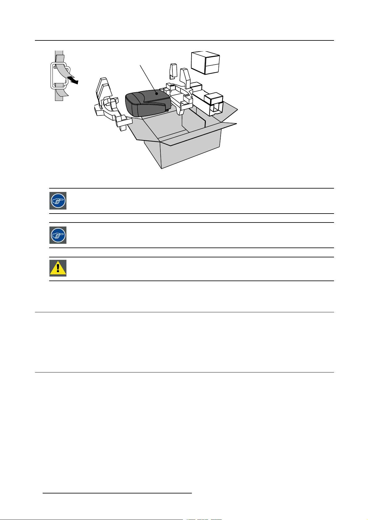
Way of Packaging
The projector is packed in a carton box. To provide protection during transpor
package is secured with banding and fastening clips.
How to Unpack?
1. Release the fastening clips.
2. Remove the banding. Handle as shown in the drawing. (image 2-1)
3. Take the projector out of its shipping carton and place it on a table. (image 2-2)
tation, the projector is surrounded with foam. The
R5976870 BARCOREALITY SIM 5PLUS/SIM 5R 04/04/2007
7
Page 12
2. Packaging and Dimensions
SIM 5 Plus
PULL
TO OPE
Image 2-1
Remove the banding
Image 2-2
Take the projector out of its shipping carton
Save the original shipping carton and packing material, they will be necessary if you ever have to ship your
projector. For maximum protection, repack your projector as it was originally packed at the factory.
Save the original shipping carton and packing material, they will be necessary if you ever have to ship your
projecto
r. For maximum protection , repack your projector as it was originally packed at the factory.
CAUTION: Never transport the projector with the lens mounted on it !
Always remove the lens before transporting the projector.
2.3 Weight
ht
Weig
• Projector body: 12.9 kg (28.4 lb)
• Shipping weight: 17.5 kg (38.6 lb)
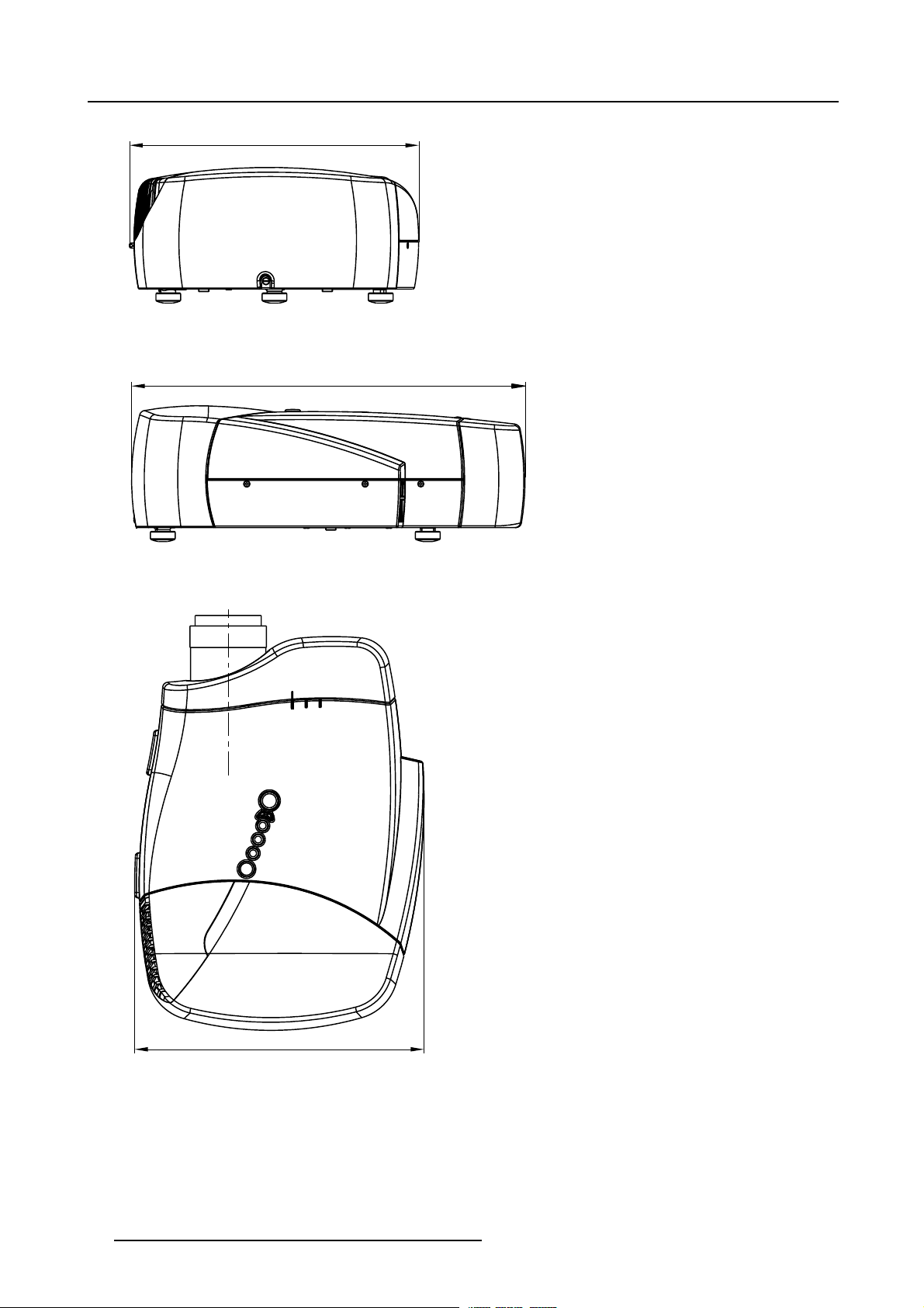
2.4 Dimensions
Dimensions
The dimensions are given in mm and inch (25,4mm = 1 inch).
8
R5976870 BARCOREALITY SIM 5PLUS/SIM 5R 04/04/2007
Page 13
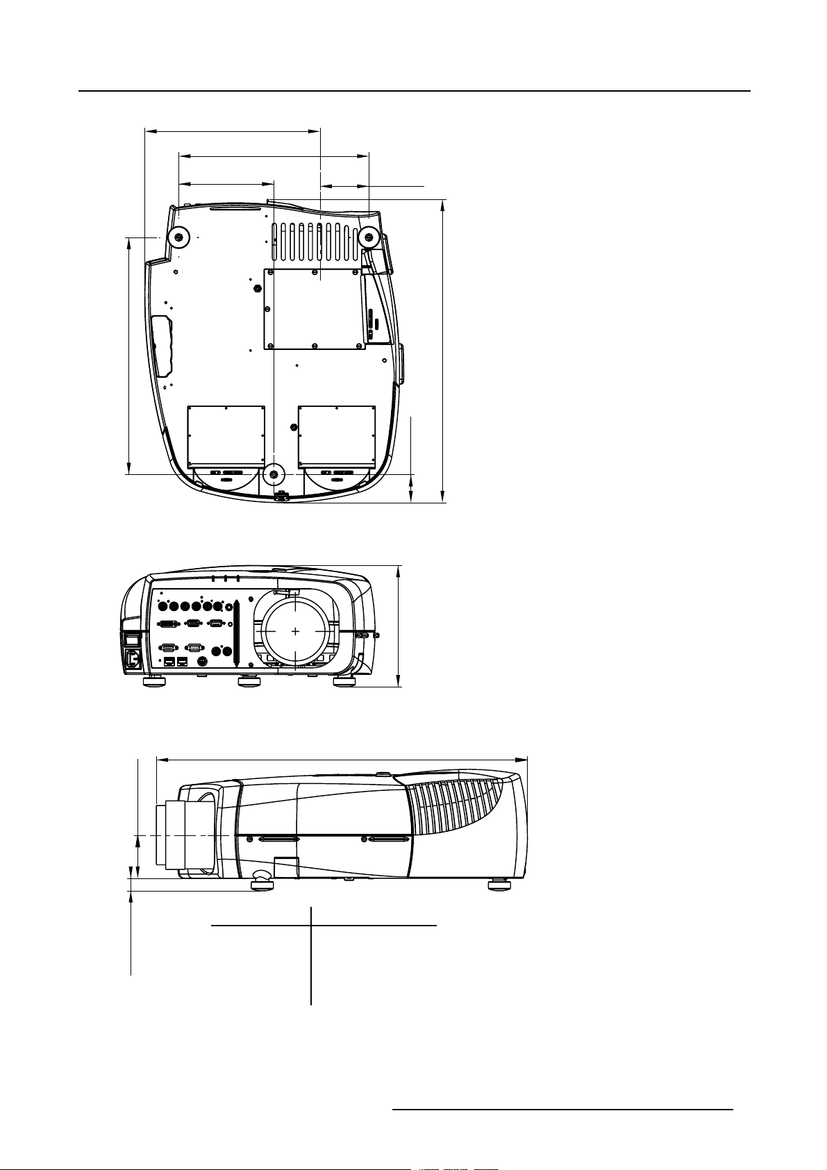
281 mm
(11.06 inch)
152,6 mm
(6.01 inch)
2. Packaging and Dimensions
305,2 mm
(12.02 inch)
78,6 mm
(3.09 inch)
380,6 mm
(14.98 inch)
Image 2-3
Bottom view dimensions
Image 2-4
Front view dimensions
45 mm
0
0
+12
+0.47
195 mm
(7.68 inch)
Length with different lenses: See table
(19.17 inch)
487 mm (Length without Cable Basket)
(1.77 inch)
-0.16
+0.47
-4
+12
69 mm
(2.72 inch)
Lens Length of Projector
QCLD (0.85:1) 610 mm (24.02 inch)
QCLD (1.1-1.3:1) 580 mm (22.84 inch)
CLD (1.2-1.6:1) 530 mm (20.87 inch)
CLD (1.6-2.4:1) 525 mm (20.67 inch)
+12
0
20 mm
0
+0.47
(0.79 inch)
CLD (2.4-4.3:1) 550 mm (21.65 inch)
Image 2-5
Left view dimensions
R5976870 BARCOREALITY SIM 5PLUS/SIM 5R 04/04/2007 9
Page 14
2. Packaging and Dimensions
415 mm
(16.34 inch)
Image 2-6
Rear view dimensions
Image 2-7
Right view dimensions
565 mm (Length with Cable Basket)
(22.24 inch)
415 mm
(16.34 inch)
Image 2-8
Top view dimensions
10 R5976870 BARCOREALITY SIM 5PLUS/SIM 5R 04/04/2007
Page 15
3. INSTALLATION GUIDELINES
Overview
• Safety Warnings
• General Installation Guidelines
• Projector Position
•Airflow
• Projector Configuration
• Available Lens Types
• Lens Formulas
• Lens Installation
• Lens Shift Capability
• Scheimpflug Lens Adjustment
• Cleaning the lens
• Battery Installation
WARNING: Before installing the projector, read first the safety instructions supplied with the BarcoReality
SIM 5plus.
3. Installation Guidelines
3.1 Safety Warnings
Mercury Vapor Warnings
Keep the following warnings in mind when using the projector. The lamp used in the projecto
rupture, explosion there will be a mercury vapor emission. In order to minimize the potential risk of inhaling mercury vapors:
• Ensure the projector is installed only in ventilated rooms.
• Replace the lamp module before the end of its operational life.
• Promptly ventilate the room after a lamp rupture, explosion has occurred, evacuate the room (particularly in case of a pregnant
woman).
• Seek medical attention if unusual health conditions occur after a lamp rupture, ex
of breath, chest-tightening coughing or nausea.
r contains mercury. In case of a lamp
plosion, such as headache, fatigue, shortness
3.2 General Installation Guidelines
Ambient Temperature Conditions
Careful consideration of things such as image size, ambient light level, projector placement and type of screen to use are critical to
the optimum use of the projection system.
Min. ambient temperature : 10°C or 50°F.
Max. ambient temperature : 40°C or 104°F.
The projector will not operate if ambient air temperature falls outside t
Storage temperature: -35°C to +65°C (-31°F to 149°F).
Humidity Conditions
Storage: 0 to 98 % RH Non-condensing.
Operation: 0 to 95 % RH Non-condensing.
his range 10°C to 40°C (50°F to 104°F).
CAUTION: Harmful Environmenta l Contamination Precaution
R5976870 BARCOREALITY SIM 5PLUS/SIM 5R 04/04/2007 11
Page 16

3. Installation Guidelines
Environment
Do not install the projection system in a site near heat sources such as radiators or air ducts, or in a place subject to direct sunlight,
excessive dust or humidity. Be aware that room heat rises to the ceiling; check that temperature near the installation site is not
excessive.
Environment Condition Check
A projector must always be mounted in a manner which ensures the free flow of clean air into the projectors ventilation inlets. For
installations in environments where the projector is subject to airborne contaminants such as that produced by smoke machines or
similar (these deposit a thin layer of greasy residue upon the projectors internal optics and imaging electronic surfac
performance), then it is highly advisable and desirable to have this contamination removed prior to it reaching the projectors clean
air supply. Devices or structures to extract or shield contaminated air well away from the projector are a prerequisite, if this is not a
feasible solution then measures to relocate the projector to a clean air environment should be considered.
Only ever use the manufactures recommended cleaning kit which has been specifically designed for cleaning optical parts, never
use industrial strength cleaners on a projectors optics as these will degrade optical coatings and damage sensitive optoelectronics
components. Failure to take suitable precautions to protect the projector from the effects of persistent and prolonged air contaminants will culminate in extensive and irreversible ingrained optical damage. At this stage cleaning of the internal optical units will be
non-effective and impracticable. Damage of this nature is under no circumstances covered under the manufactures warranty and
may deem the warranty null and void. In such a case the client shall be held solely responsible for all costs incurred during any
repair. It is the clients responsibility to ensure at all times that the projector is protected from the harmful effects of hostile airborne
particles in the environment of the projector. The manufacture reserves the right to refuse repair if a projector has been subject to
wantful neglect, abandon or improper use.
What about Ambient Light?
The ambient light level of any room is made up of direct or indirect sun
light will determine how bright the image will appear. So, avoid direct light on the screen. Windows that face the screen should be
covered by opaque drapery while the set is being viewed. It is desirable to install the projection system in a room whose walls and
floor are of non-reflecting material. The use of recessed ceil
is also important. Too much ambient light will ‘wash out’ of the projected image. This appears as less contrast between the darkest
and lightest parts of the image. With bigger screens, the ‘wash out’ becomes more important. As a general rule, darken the room to
the point where there is just sufficient light to read or wr
interference with the screen is minimal.
ing lights and a method of dimming those lights to an acceptable level
ite comfortably. Spot lighting is desirable for illuminating small areas so that
light and the light fixtures in the room. The amount of ambient
es, degrading
Special Care for Laser Beams
Special care should be used when DLP projectors are used in the same room as performant laser equipment. Direct or indirect
hitting of a laser beam on to the lens can severely damage the Digital Mirror Devices (TM) in which case there is a loss of warranty.
Which Screen Type?
There are two major categories of screens used f
projection applications.
Screens are rated by how much light they reflect (or transmit in the case of rear projection systems) given a determined amount
of light projected toward them. The ‘GAIN’ of a screen is the term used. Front and rear screens are both rated in terms of gain.
The gain of screens range from a white matte screen with a gain of 1 (x1) to a brushed aluminized screen with a gain of 10 (x10)
or more. The choice between higher and lower gain screens is largely a matter of personal preference and another consideration
called the Viewing angle. In considering the type of screen to choose, determine where the viewers will be located and go for the
highest gain screen possible. A high gain screen will provide a brighter picture but reduce the viewing angle. For more information
about screens, contact your local screen supplier.
or projection equipment. Those used for front projected images and those for rear
What Image Size?
The projector is designed for projecting an image size from 1.00m (3.3ft) to 6.00m (19.7ft) with an aspect ratio of 4 to 3.
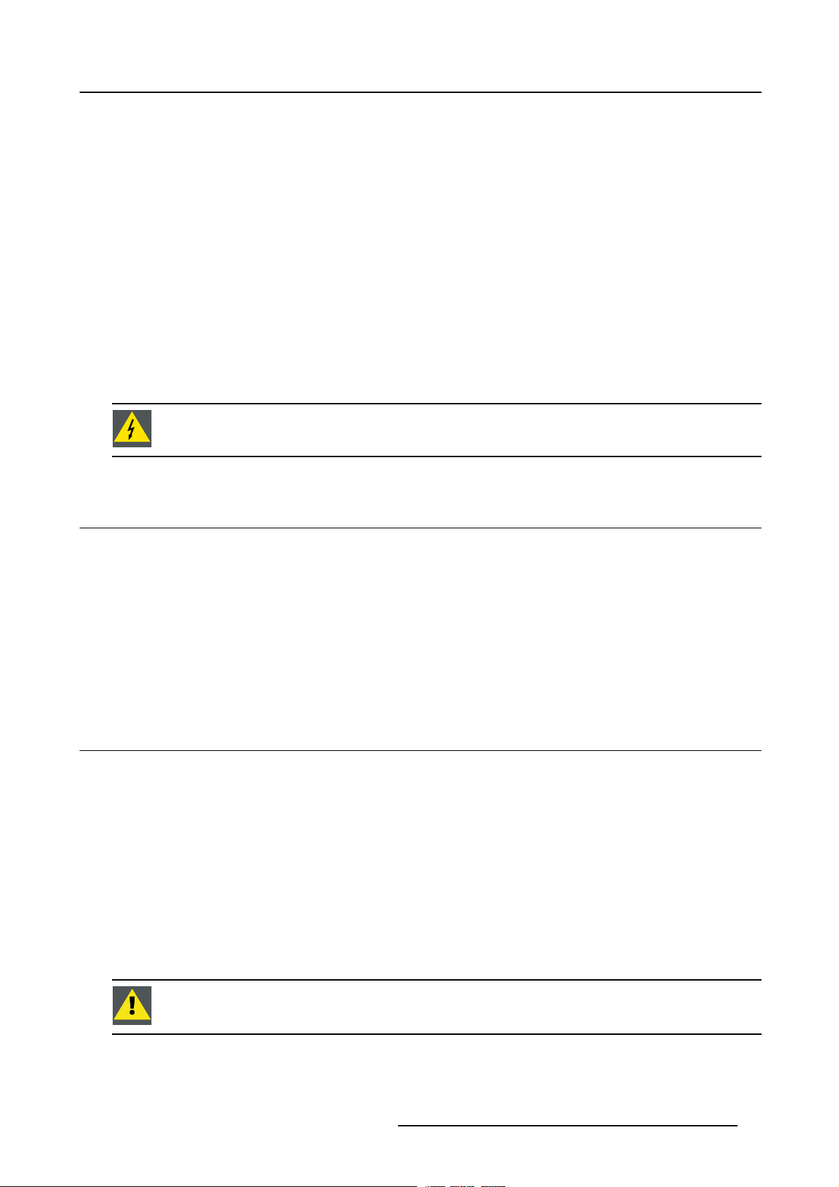
3.3 Projector Position
CAUTION: Improper positioning of the projector may reduce the lamplife and result in severe accident orfire
hazard.
Projector Position
Keep following projector position guidelines in mind when installing the projector:
12
R5976870 BARCOREALITY SIM 5PLUS/SIM 5R 04/04/2007
Page 17
• +/- 20° roll around projector lens
3. Installation Guidelines
+20° Roll around projector lens
Image 3-1
+/- 20° roll around projector lens
-20° Roll around projector lens
R5976870 BARCOREALITY SIM 5PLUS/SIM 5R 04/04/2007 13
Page 18
3. Installation Guidelines
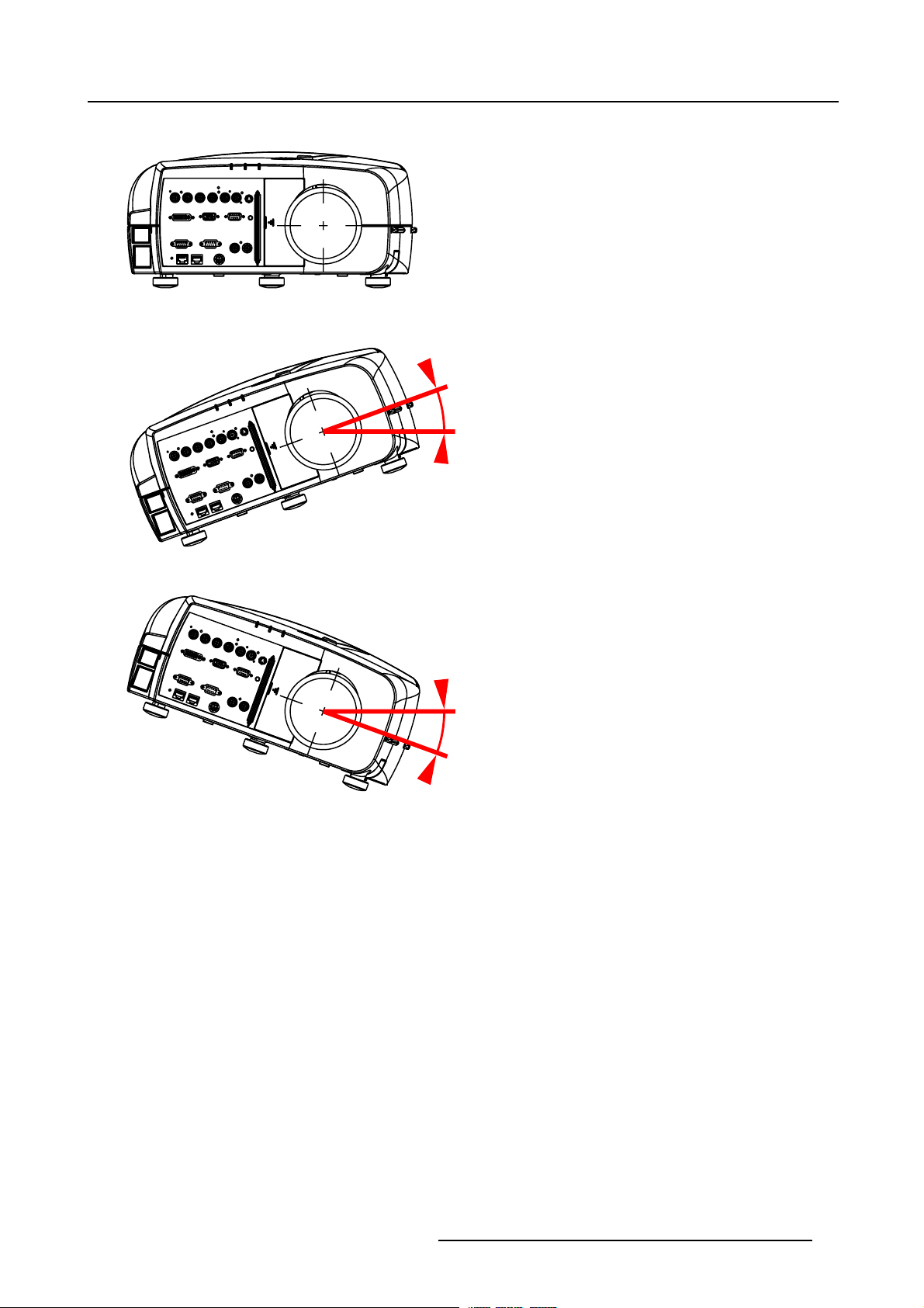
• full pitching allowed (360°)
Full pitching
allowed (360°)
Image 3-2
Full pitching allowed (360°)
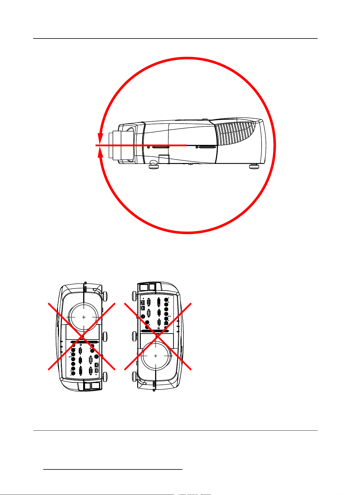
• Do not put the projector on either side to project an image
Do not put the projector
on either side
to project an image!
Image 3-3
Do not put the projector on either side to project an image
3.4 Airflow
Airflow
The Air Intake Vent is located on the bottom side of the projector while the Exhaust Vent can be found on the left rear side of the
projector. Make sure the projector is installed in a location so that the air inlets and outlets for the cooling system are not obstructed.
14
R5976870 BARCOREALITY SIM 5PLUS/SIM 5R 04/04/2007
Page 19
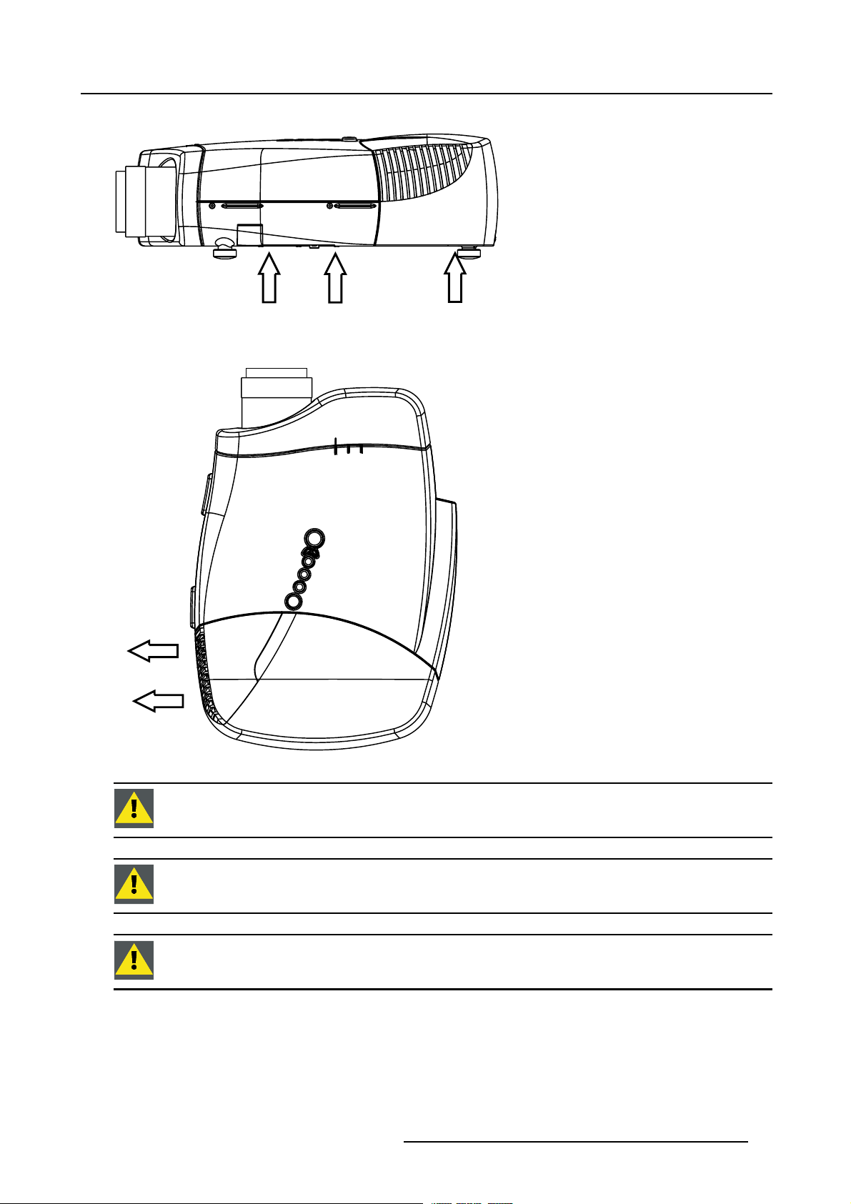
• Air intake vent
3. Installation Guidelines
Image 3-4
Air intake vent
• Exhaust vent
Hot Air Out
Cold Air In Cold Air In
Image 3-5
CAUTION: Toprotect the BarcoReality SIM 5plus from overheating do not cover or block theair intake and/or
exhaust vent.
CAUTION: Do not place flammable objects near the Exhaust Vent.
CAUTION: Do not touch the Exhaust Vent Grill when the projector is switched on, this part will become hot
during operation.
R5976870 BARCOREALITY SIM 5PLUS/SIM 5R 04/04/2007 15
Page 20
3. Installation Guidelines
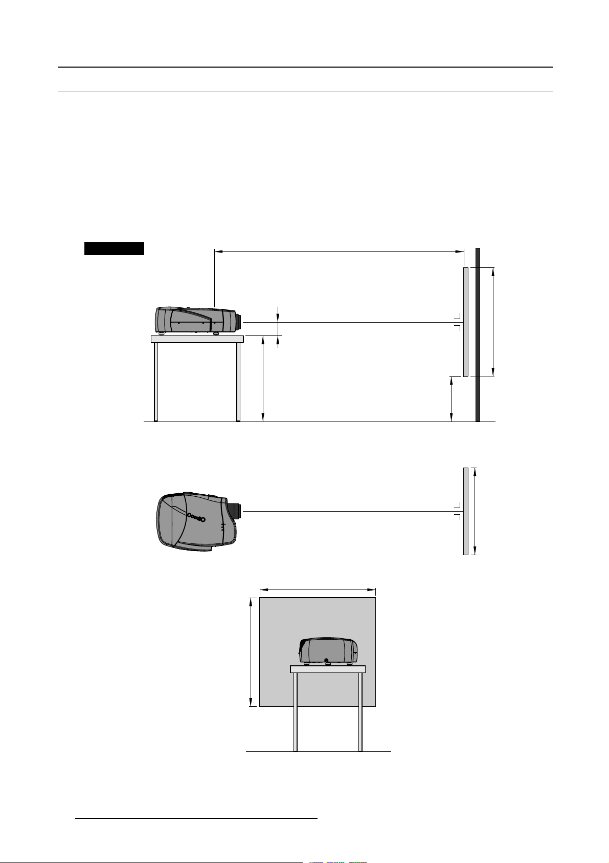
3.5 Projector Configuration
Available Configurations
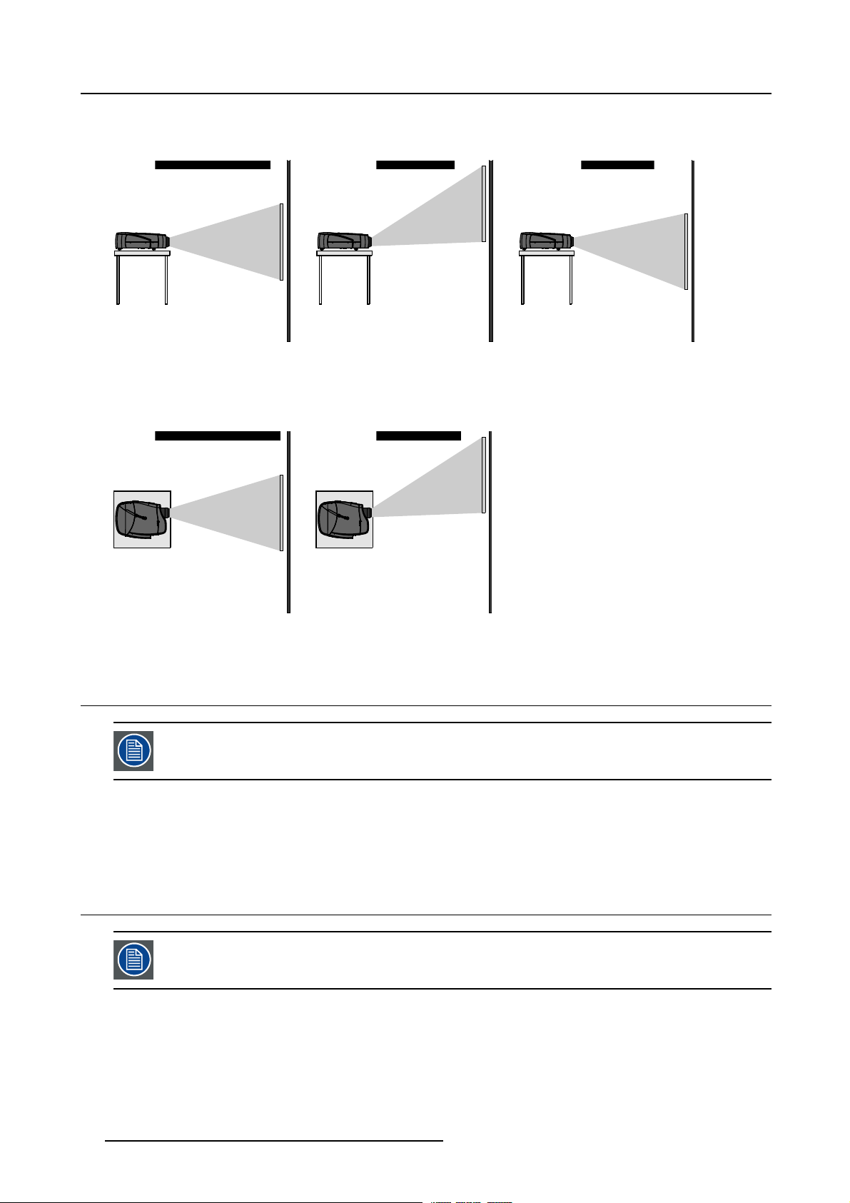
The projector can be installed to project images in four different configurations:
• Front Table
• Front Ceiling
• Rear Table
• Rear Ceiling
Positioning the Projector
The projector should be installed perpendicular with the screen on a distance PD (Projector Position) and water leveled in both
directions. The mounting positions in following images are shown for a nominal lens position.
Front Table
Side view
Top view
Projector
A
CD=SH/2+B-A
PD
Optical axis projection lens
Floor
SH
Screen
B
SW
Screen
SW
Back view
Image 3-6
Front Table Configuration
16 R5976870 BARCOREALITY SIM 5PLUS/SIM 5R 04/04/2007
SH
Floor
Page 21
3. Installation Guidelines
W
W
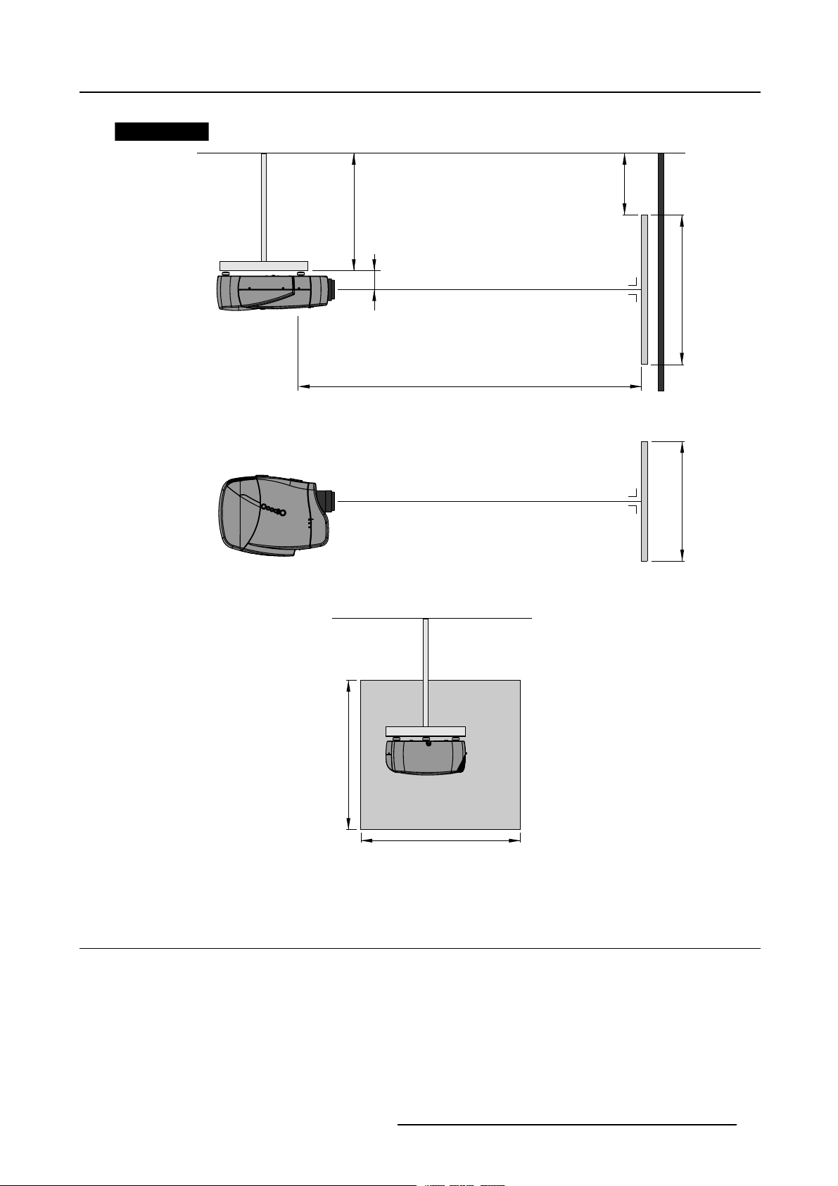
Front Ceiling
Side view
Bottom view
Projector
Ceiling
CD=SH/2+B-A
A
B
Optical axis projection lens
SH
Screen
PD
S
Back view
Image 3-7
Front Ceiling Configuration
3.6 Available Lens Types
Screen
Ceiling
SH
S
Standard Non-Motorized Lens
Non-motorized lens: manual zoom and focus adjustment.
R5976870 BARCOREALITY SIM 5PLUS/SIM 5R 04/04/2007
17
Page 22
3. Installation Guidelines
• QCLD 1.1 – 1.3 :1 (Full off-axis)
Optional Motorized Lenses
Motorized lens: motorized zoom and focus adjustment.
• CLD 1.2 – 1.6 :1 (Full off-axis)
• CLD 1.6 – 2.4 :1 (Full off-axis)
• CLD 2.4 – 4.3 :1 (Full off-axis)
Optional Fixed Lens
Fixed lens: manual focus adjustment.
• QCLD0.85:1(On-axis)
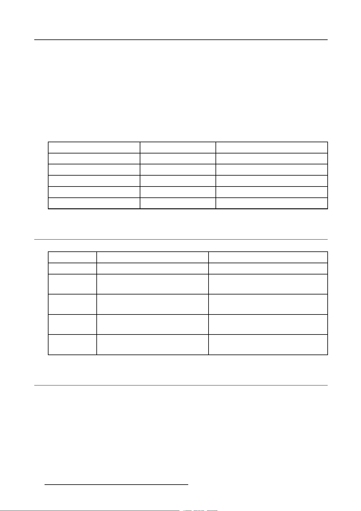
Product Numbers
Lens
QCLD (0.85:1)
QCLD (1.1-1.3:1)
CLD (1.2-1.6:1)
CLD (1.6-2.4:1)
CLD (2.4-4.3:1)
Product Number
Product Number (Scheimpflug Version)
R9849860 R9849862
R9849850 R9849852
R9849870 R9849872
R9849880 R9849882
R9849890 R9849892
3.7 Lens Formulas
Formulas
Lenses
QCLD (0.85:1) PD=0.86XSW+0.06 PD = 0.86 X SW + 2.36
QCLD (1.1-1.3:1) PD
CLD (1.2-1.6:1) PD
CLD (1.6-2.4:1) PD
Metric Formulas (meter) Inch formulas (inch)
= 1.1 X SW + 0.05
min
=1.3XSW+0.06
PD
max
=1.19XSW+0.02
min
=1.63XSW+0.02
PD
max
=1.58XSW+0.00
min
= 2.39 X SW - 0.02
PD
max
PD
min
PD
max
PD
=1.19XSW+0.79
min
=1.63XSW+0.79
PD
max
PD
=1.58XSW+0.00
min
PD
max
=1.1XSW+1.97
= 1.3 X SW + 2.36
= 2.39 X SW - 0.79
CLD (2.4-4.3:1) PD
= 2.38 X SW - 0.03
min
PD
= 4.32 X SW - 0.01
max
PD
= 2.38 X SW - 1.18
min
PD
= 4.32 X SW - 0.39
max
3.8 Lens Installation
Necessary tools
No tools.
How to install the Lens?
1. Take the lens out of its packing material.
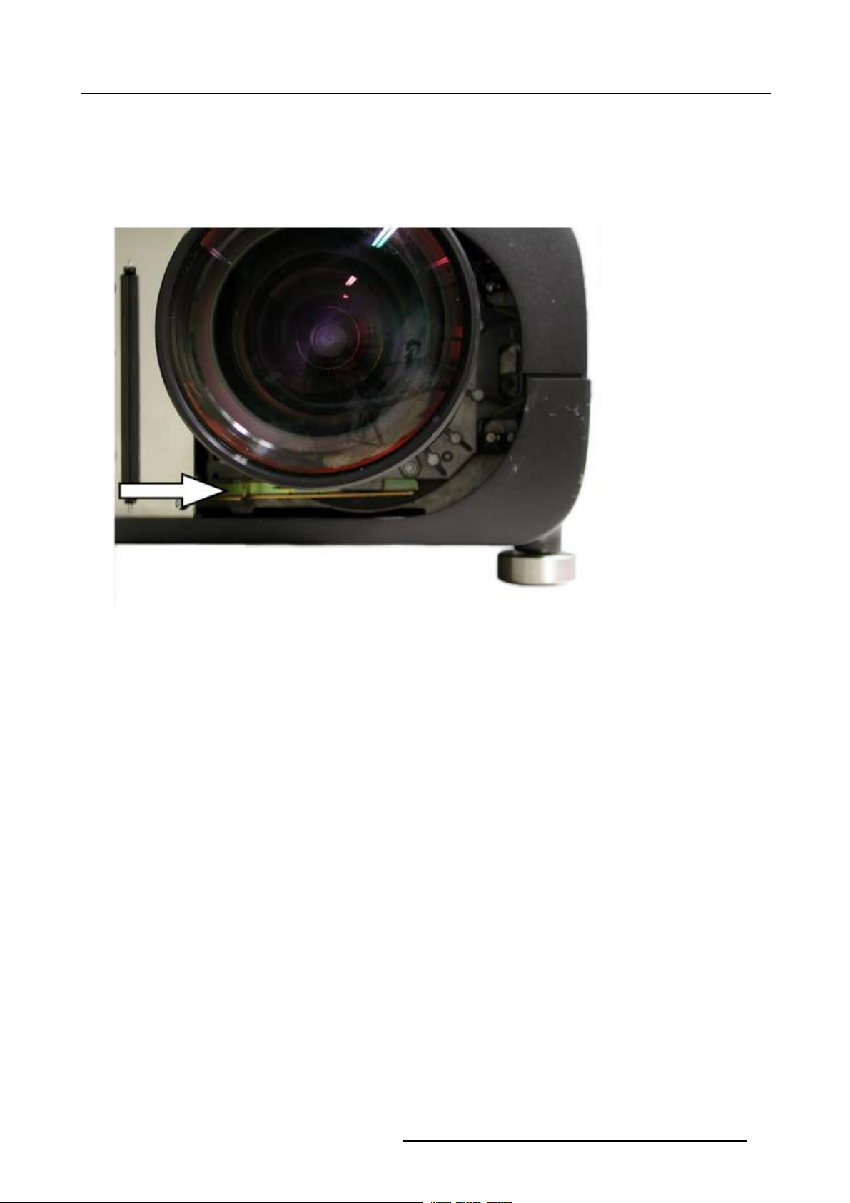
2. Make sure the lens lock holder is in the left position. (image 3-8)
3. Lock the lens by placing it in the housing, push carefully to lock (“click” sound) the lens in the housing. (image 3-9)
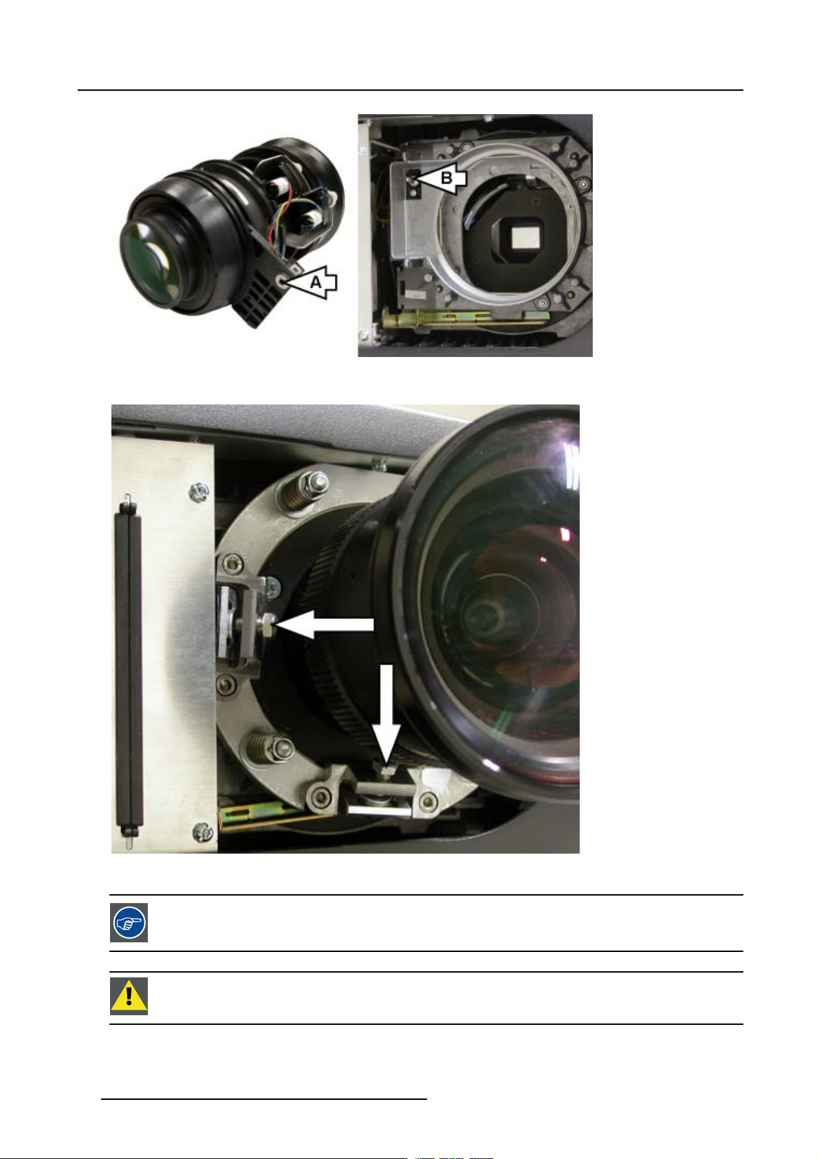
Caution: In case ofa motorizedlensthe female jack onthe lens(A) mustbein front of them ale jack(B) locatedin theu pper-le ft
Note: In case ofa Scheimpflug lens,insert the lenswith the adjustmentbolts locatedin the leftand bottom position. (image3-11)
18
part of the housing in the projector. (image 3-10)
R5976870 BARCOREALITY SIM 5PLUS/SIM 5R 04/04/2007
Page 23
3. Installation Guidelines
Image 3-8
Make sure the lens lock holder is in the left position.
Image 3-9
R5976870 BARCOREALITY SIM 5PLUS/SIM 5R 04/04/2007 19
Page 24
3. Installation Guidelines
Image 3-10
The female jack on the lens (A) must be in front of the male jack (B) located in the upper-left p
art of the housing in the projector.
Image 3-11
In case of a Scheimpflug lens, insert the lens with the adjustment bolts located in the left and bottom position.
A Scheimpflug lenswill limit shift possibilities. Mount the lens depending on the application(adjustment bolts
located in theleft andbottom position to allowmaximum shift upand in the left/topposition to allowmaximum
shift down)
CAUTION: The projecto r is delivered by default with a 100% upward shifted position. To mount the
Scheimpflug lens, first shift down.
20 R5976870 BARCOREALITY SIM 5PLUS/SIM 5R 04/04/2007
Page 25
3. Installation Guidelines
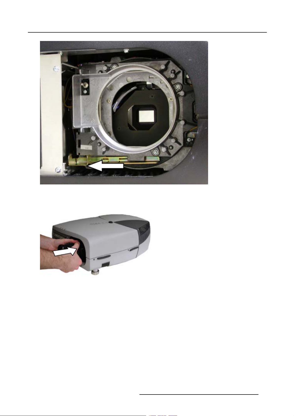
How to remove the Lens?
1. Support the lens with one hand.
2. The lens lock handle is located on the front side of the projector, slide this handle to the right. (image 3-12)
3. Remove the lens out of its housing.
4. Slide the lens lock handle back to the left.
Image 3-12
The lens lock handle is located on the front side of the projector, slide this handle to the right.
3.9 Lens Shift Capability
Introduction
The integrated Lens Shift Capabilities make the BarcoReality SIM 5plus easy to install in a variety of positions without the use of
special mechanical interfaces.
R5976870 BARCOREALITY SIM 5PLUS/SIM 5R 04/04/2007
21
Page 26
3. Installation Guidelines
Vertical Lens Shift Range
• Off-axis adjustable Vertical Lens Shift Range: +100% to –30%:
Vertical Shift in Nominal Position
Vertical Shift : +100% Vertical Shift : -25%
Projector Projector
Screen
Image 3-13
Vertical Lens Shift Range: +100% to –30%
Screen
Projector
Horizontal Lens Shift Range
• Off-axis adjustable Horizontal Lens Shift Range: +100% in one direction (away from the inputs):
Horizontal Shift in Nominal Position Horizontal Shift : +100%
Projector
Screen
Image 3-14
Horizontal Lens Shift Range: +100% in one direction (a
Projector
Screen
way from the inputs)
Screen
3.10 Scheimpflug Lens Adjustment
The Scheimpflug Lens Version is available as an option.
Scheimpflug Lens Adjustment
For more info on how to perform the Scheim
223.
pflug Lens Adjustment on a Scheimpflug lens see "Scheimpflug Lens Adjustment", page
3.11 Cleaning the lens
To minimize the possibility of da
recommendations for cleaning. FIRST, we recommend you try toremove anymaterial from the lensby blowing
it off with clean, dry deionized air. DO NOT use any liquid to clean the lenses.
Necessary tools
To ra ys e eTMcloth (delivered together with the lens kit). Order number : R379058.
Howtocleanthelens?
Proceed as follow :
1. Always wipe lenses with a CLEAN Toraysee
mage to optical coatings, or scratches to lens surfaces, we have developed
TM
cloth.
22
R5976870 BARCOREALITY SIM 5PLUS/SIM 5R 04/04/2007
Page 27
3. Installation Guidelines
RCU T
2. Always wipe lenses in a single direction.
Warning: Do not wipe back and forwards across the lens surface as this tends to grind dirt into the coating.
3. Do not leave cleaning cloth in either an open room or lab coat pocket, as doing so can contaminate the cloth.
4. If smears occur when cleaning lenses, replace the cloth. Smears are the first indication of a dirty cloth.
CAUTION: Do not use fabric softener when washing the cleaning cloth or softener sheets when drying the
cloth.
Do not use liquid cleaners on the cloth as doing so will contaminate the cloth.
Other lenses can also be cleaned safely with this TorayseeTMcloth.
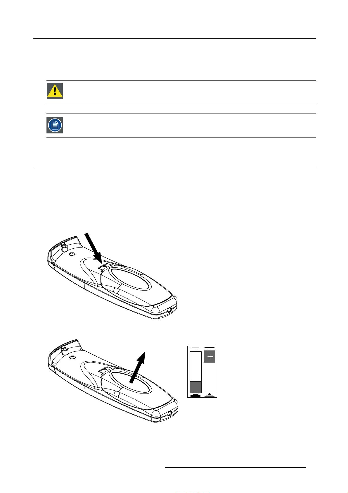
3.12 Battery Installation
How to install?
The batteries, not yet installed to save the battery life time, are delivered inside the plastic bag with the power cord.
1. Remove the battery cover on the backside of the remote control by pushing the indicated handle a little towards the bottom of
the RCU. (image 3-15)
2. Lift up the top side of the cover at the same time. (image 3-16)
3. Insert the 2 new 1,5 V batteries as indicated in the RCU. (image 3-17)
4. Put the battery cover back in place.
Image 3-15
Push the indicated handle
op
+
Image 3-17
Insert the 2 batteries
Image 3-16
Lift up the cover
R5976870 BARCOREALITY SIM 5PLUS/SIM 5R 04/04/2007 23
Page 28

3. Installation Guidelines
24 R5976870 BARCOREALITY SIM 5PLUS/SIM 5R 04/04/2007
Page 29
4. CONNECTIONS
Overview
• Connections Overview
• Power Cord Connection
• Source Input Connections
• Communication Connections
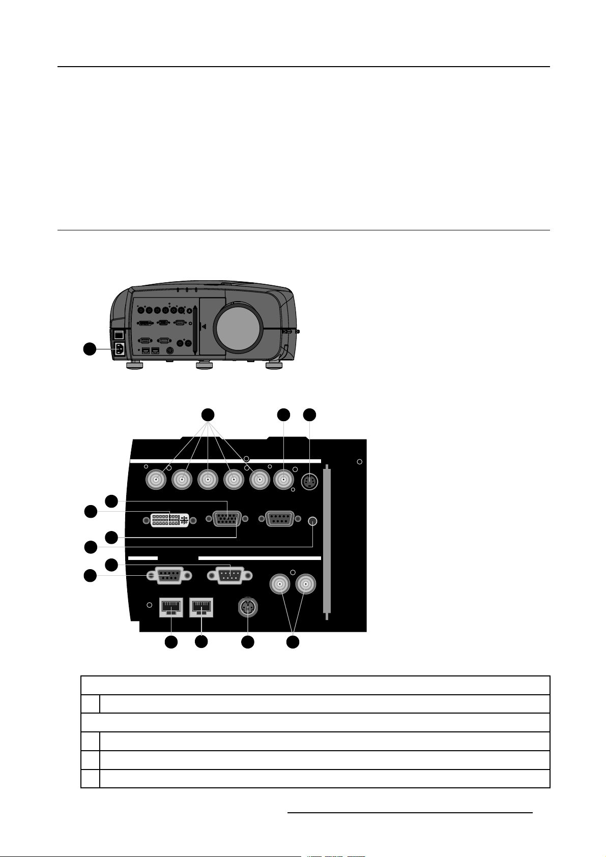
4.1 Connections Overview
Connections Overview
The following table gives an overview of the available connections found on the BarcoReality SIM 5plus:
I
0
1
4. Connections
Image 4-1
Power Cord Connection
6
5
9
14
11
10
Image 4-2
Connections Overview
2
R / PR G / Y B / PB Hs / Cs Vs Optional
DVI
Communication
12
COMPUTER RS 232 C
RS232/422 OUTRS232/422 IN
IN L/R Signal10/100Base-T
13
7 8
3 4
OUT Phased L/R Signal
Optional
R.C.
Power Cord Connection
1
Power Cord Connection
Source Input Connections
2
5–BNC Cable Input
3
For future expansion
4
For future expansion
R5976870 BARCOREALITY SIM 5PLUS/SIM 5R 04/04/2007 25
Page 30
4. Connections
5
DVI Input (Single link up to 165 MHz)
6
VGA D15 connector
Stereo Connections
7
Not used
8 Not used
Communication Connections
9
RS232 Input (DB9 connector)
10
RS232/422 In (DB9 connector)
11
RS232/422 Out (DB9 connector)
12
10/100 Base-T In
13
10/100 Base-T Out / Link
14 Not used
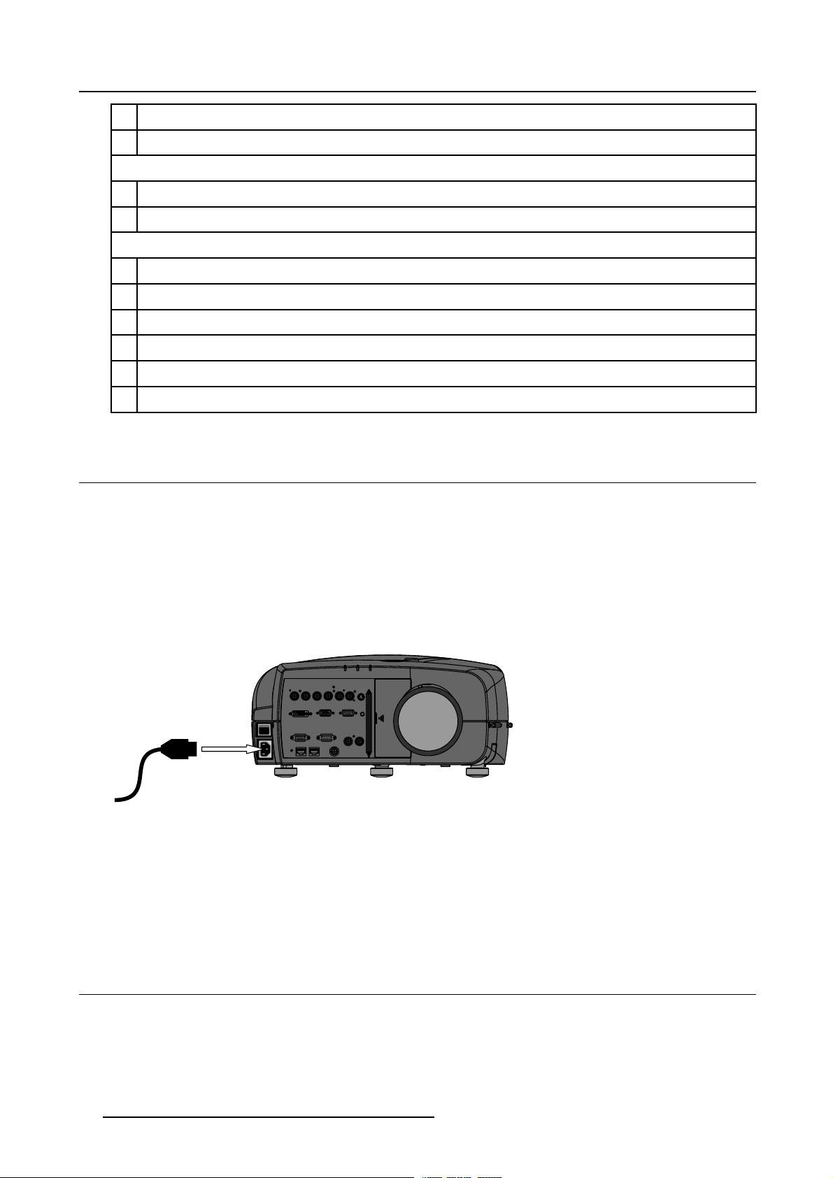
4.2 Power Cord Connection
Power Input Range
The power input is auto-ranging from 90–254 VAC @ 50/60 Hz.
Power Consumption
Power Consumption of 1 BarcoReality SIM 5plus is 750 W.
Power Cord Connection
1. Use the supplied power cord to connect your projector to the wall outlet. Plug the female power connector into the male connector
at the front of the projector. (image 4-3)
I
0
to wall outlet
Image 4-3
Power Cord Connection
Fuses
For continued protection against fire hazard:
• Refer replacement to qualified service personnel.
• Ask to replace with the same type of fuse.
4.3 Source Input Connectio
Overview
• 5–Cable Input
• DVI Input
• Computer Input
26
ns
R5976870 BARCOREALITY SIM 5PLUS/SIM 5R 04/04/2007
Page 31

4.3.1 5–Cable Input
Which signals can be connected to the 5–Cable Input?
4. Connections
Input Signal / BNC
R
G
B H V
Connector
RGBHV
RGBS
RGsB
R
R
R
G
G
Gs
B H V
B
B
S
– –
Option
To display Component, the software option (ROPT202
3) has to be activated.
How to connect to the 5–Cable Input?
1. Connect the BNC’s from the source signal output cable to the 5–Cable Input on the projector. (image 4-4)
Sim 5 plus Inputs
–
Image Generator
Image 4-4
5–Cable Input
4.3.2 DVI Input
DVI
Digital Visual Interface is a display interface developed in response to the proliferation of digital flat panel displays.
The digital video connectivity standard that was developed by DDWG (Digital Display Work Group). This connection
standard offers two different connectors: one with 24 pins that handles digital video signals only, and one with 29 pins
that handles both digital and analog video. This standard uses TMDS (Transition Minimized Differential Signal) from
Silicon Image and DDC (Display Data Channel) from VESA (Video Electronics Standards Association).
DVI
R / PR G / Y B / PB Hs / Cs Vs Optional
DVI
Communication
canbesingleorduallink.
COMPUTER RS 232 C
RS232/422 OUTRS232/422 IN
OUT Phased L/R Signal
IN L/R Signal10/100Base-T
Optional
R.C.
How to connect the DVI Input?
nect the DVI connector from the source signal output cable to the DVI Input on the projector. (image 4-5)
1. Con
R5976870 BARCOREALITY SIM 5PLUS/SIM 5R 04/04/2007
27
Page 32

4. Connections
Sim 5 plus Inputs
Image Generator
Image 4-5
DVI Input
R / PR G / Y B / PB Hs / Cs Vs Optional
DVI
Communication
COMPUTER RS 232 C
RS232/422 OUTRS232/422 IN
OUT Phased L/R Signal
IN L/R Signal10/100Base-T
Optional
R.C.
4.3.3 Computer Input
How to connect the Computer Input?
1. Connect the VGA D15 connector from the source signal output cable to the DVI Input on the projector. (image 4-6)
28
R5976870 BARCOREALITY SIM 5PLUS/SIM 5R 04/04/2007
Page 33

Computer
4. Connections
Magik Interface II
(R9828122)
Input Output
Sim 5 plus Inputs
Image 4-6
Computer Input
Always use an interface (e.g. Barco’s Magik II Interface R9828122) when a computer and local monitor have
to be connected to the projector as the sig
interferences.
4.4 Communication Connections
Overview
• RS232/RS422 Connections
• Ethernet Connections
R / PR G / Y B / PB Hs / Cs Vs Optional
DVI
Communication
COMPUTER RS 232 C
RS232/422 OUTRS232/422 IN
OUT Phased L/R Signal
IN L/R Signal10/100Base-T
Optional
R.C.
nal cable coming from the projector is limited to 60 cm due to
4.4.1 RS232/RS422 Connections
What is possible with the RS232/RS422 Connections?
1. Remote control :
- easy adjustment of projector when connected to an IBM PC (or compatible) or Apple computer.
- allow storage of multiple project
or configurations and set ups.
- wide range of control possibilities.
- address range from 0 to 255.
2. Data communications: sending data to the projector or copying the data from the projector to a memory device (hard disc,
floppy, etc.).
How to conne ct the RS232/RS422 ports?
1. Connect the D9 connector from the R
2. When applicable connect the RS232/RS422 Output to the next projector in the daisy chain setup.
R5976870 BARCOREALITY SIM 5PLUS/SIM 5R 04/04/2007
S232/RS422 cable to the RS Input on the projector. (image 4-7)
29
Page 34

4. Connections
PC Serial Port
To RS IN Port
on next projector
R / PR G / Y B / PB Hs / Cs Vs Optional
DVI
Communication
Image 4-7
RS232/RS422 Connections
COMPUTER RS 232 C
RS232/422 OUTRS232/422 IN
OUT Phased L/R Signal
IN L/R Signal10/100Base-T
Optional
R.C.
4.4.2 Ethernet Connections
What is possible with the Ethernet Connections?
The Ethernet Connections can be used to:
• Upload or download projector software.
• Set up RS232 communication (TCP-packets) with the projector.
How to connect the Ethernet ports?
1. Plug one end of the TCP/IP cable into the PC or the network socket. (image 4-8)
2. Connect the other end of the TCP/IP cable in
The orange led will light up when network activity is detected.
to the ’Ethernet In’ port on the projector.
30
R5976870 BARCOREALITY SIM 5PLUS/SIM 5R 04/04/2007
Page 35

10/100 Base-T
4. Connections
R / PR G / Y B / PB Hs / Cs Vs Optional
DVI
Communication
Image 4-8
Ethernet Connections
COMPUTER RS 232 C
RS232/422 OUTRS232/422 IN
IN L/R Signal10/100Base-T
Optional
R.C.
OUT Phased L/R Signal
R5976870 BARCOREALITY SIM 5PLUS/SIM 5R 04/04/2007 31
Page 36

4. Connections
32 R5976870 BARCOREALITY SIM 5PLUS/SIM 5R 04/04/2007
Page 37

5. GETTING STARTED
5.1 Operating the Projector
How to Operate the Projector?
The projector can be controlled by using:
• the Remote Control Unit (RCU).
• the Local Keypad on top of the Projector.
• the RS232 commands.
5.2 RCU Terminology Overview
What keys can be found on the RCU?
5. Getting Started
1
2
3
4
5
6
7
8
9
10
Image 5-1
RCU Overview
F2
F1
F3
MENU BACK
PAUSE
AUTO IMAGE
9
SDI
7
5
VIDEO
34
1
LENS
ZOOM
LENS
FOCUS
PIP
LOGO
DIGI
ZOOM
0
PHASE
IQ-PC
8
TINT
Fire WireDVI
6
COLOR
S-VIDEO
BRIGHTN
PCRGB
2
CONTR
LENS
SHIFT
VOL
ENTER
19
18
17
16
15
14
13
12
11
The following table gives an overview of the different functionalities of the keys that can be found on the RCU:
1 Function keys Not used
2 MENU Menu key, to enter or exit the Toolbar menu
3 Address key
(Recessed key), to enter the address of the projector (between 0 and 9). Press the recessed
address key with a pencil, followed by pressing one digit button between 0 and 9
4
LOGO Switch between displaying the internal or external pattern in the Geometry Distortion and the
Shape (Blanking) dialogbox.
5
PAU SE To stop projection for a short time, press ’PAUSE’. The image disappears but full power is
retained for immediate restarting.
6
STANDBY Standby button, to start projector when the power switch is switched on and to switch off the
projector without switching off the power switch
Attention: Switching to Standby. W
hen the projector is running and you want to go to
standby, press the standby key for 2 seconds.
R5976870 BARCOREALITY SIM 5PLUS/SIM 5R 04/04/2007 33
Page 38

5. Getting Started
7
MUTE Not used
8 Auto image Not used
9 Digit buttons Direct input selection
10 Lens control
11
VOL
12
Picture Controls
13
DIGI ZOOM
14 FREEZ Not used
15 PIP Not used
16 ENTER
17
Cursor keys To make menu selections, to perform bare scale adjustments or to zoom/focus when the direct
18
BACK To leave the selected menu or item (go upwards to previous menu)
19
RCU operation
indication led
Use these button to obtain the desired ZOOM, SHIFT, FOCUS
Not used
Use these buttons to obtain the desired picture analog level
Not used
To confirm an adjustment or selection in the menu
access is active
Lights up when a button on the remote control is pressed. (This is a visual indicator to check
the operation of the remote control)
5.3 Local Keypad Terminology Overview
What keys can be found on the Local Keypad?
Local Keypad
LENS
SOURCE
19
20
21
22
23
24
25
e5-2
Imag
l Keypad Overview
Loca
34 R5976870 BARCOREALITY SIM 5PLUS/SIM 5R 04/04/2007
Page 39

5. Getting Started
The following table gives an overview of the different functionalities of the keys that can be found on the Local Keypad:
19
Cursor keys To make menu selections, to perform bare scale adjustments or to zoom/focus when the direct
access is active
20 ENTER
21
BACK To leave the selected menu or item (go upwards to previous menu)
22
SOURCE
23 Lens control
24
STANDBY Standby button, to start projector when the power switch is switched on and to switch off the
25 IR Receiver IR Receiver
5.4 Diagnose Leds
Diagnose Leds
To start up the adjustment mode or to confirm an adjustment or selection in the adjustment mode
Not used
Use these buttons to obtain the desired ZOOM, SHIFT and FOCUS
projector without switching off the power switch
Attention:SwitchingtoStandby.Whentheprojectorisrunningandyouwanttogoto
standby, press the standby key for 2 second s.
Diagnose Leds
2
ed
D
E
L
3
D
E
L
Image 5-3
Diagnose Leds
Following diagnose leds can be found on top of the projector:
Led # / L ed Color Green
Led 1
R5976870 BARCOREALITY SIM 5PLUS/SIM 5R 04/04/2007 35
Cool down sequence: flickers 60
econds after switching to standby
s
R
Rescue program (Software error)
1
D
E
L
Page 40

5. Getting Started
Led # / L ed Color Green
Led 2 Not used Hardware error
Led 3 IR acknowledgement
5.5 Switching On
HowtoSwitchOntheProjector?
1. Press the Power Switch on the Left Front of the Projector to switch on the projector. (image 5-4)
The projector starts up in standby mode and Led 3 will light up red.
I
0
Image 5-4
Power Switch
When automatic startup is set to ’On’, the projector will immediately start with image projection (see "Automatic Startup", page 209).
Red
Standby Status
How to Start Image Projection?
1. Press the STANDBY key (or the Source Selection Shortcut Digit) on the RCU or on the Local Keypad. (image 5-5)
Note: When automaticstartup i
’On’ (see "Automatic Startup", page 209).
The projector will start up, following message will be displayed, according to the used Dynacolor™ settings, the message display
time can vary between 5 to 30 seconds. (image 5-6)
The’PleaseWait’mes
sage will disappear and the identification box will be displayed together with the selected source. After 2
seconds the identification box will disappear. (image 5-7)
F2F3F4
F1
F5
EXIT
ADJ
ENTER
PAUSE
TEXT
PHASE
9
0
SHARPN
8
7
TINT
56
COLOR
34
BRIGHTN
2
1
CONTR
TREBLE BALANCE
BASS
VOL
Image 5-5
Standby key on the RCU or Local Keypad
sset to ’On’, theprojector will immediately startwith image projectionwhen swithing theprojector
Image 5-6
SOURCE
LENS
36 R5976870 BARCOREALITY SIM 5PLUS/SIM 5R 04/04/2007
Page 41

5. Getting Started
Image 5-7
Lamp Runtime Warning
The total lamp runtime for a safe operation is max. 1500 hours, do not use it longer.
The Lamp Runtime
Warning", page 174).
The Lamp runtime warning will be displayed when this setting is reached, e.g. 30 hours before the end of the lamp runtime, and
from this moment on, at every start-up of the projector.
Warning is default set to 30 hours before the end of the lamp lifetime, to change this setting (see "Lamp Runtime
Press the BACK key on the RCU to remove this warning.
WARNING: Op
erating the lamp longer than 1500 hours may damage the projector.
WARNING: Always replace with thesame type oflamp, call a BARCO authorizedservice technician toreplace
the lamp
5.6 Switc
How t
1. Press the STANDBY key for 2 seconds to switch the projector to Standby.
5.7 Swit
hing to Standby
o Switch the Projector to Standby?
The cool down sequence is started, Led 1 will flicker for 60 seconds after switching to standby.
ching Off
and reset the lamp runtime.
w t o Switch Off the Projector?
Ho
1. First switch the projector to Standby by pressing the STANDBY key for 2 seconds.
The cool down sequence is started, Led 1 will flicker for 60 seconds after switching to standby.
2. When the cool down sequence is finished switch ’Off’ the projector with the power switch.
R5976870 BARCOREALITY SIM 5PLUS/SIM 5R 04/04/2007
37
Page 42

5. Getting Started
IR S
r
5.8 Pointing the RCU
Pointing directly to the IR Sensor on the Projector
When using the wireless remote control, make sure you are within the effective operating distance, in a straight line: 30m (100ft).
The remote control unit will not function properly if strong light strikes the sensor window or if there are obstacles between the remote
control unit and the projector IR sensor.
ensor on top of the projecto
F2F3F4
F1
F5
EXIT
ADJ
ENTER
PAUSE
TEXT
PHASE
90
SHARPN
8
7
TINT
6
5
COLOR
4
3
BRIGHTN
12
CONTR
TREBLE BALANCE
BASS VOL
Image 5-8
Pointing to the IR Sensor on the Projector
RCU
Pointing to the Reflective Screen
1. Point the front of the RCU to the reflective screen surface. (image 5-9)
Screen
RCU
Image 5-9
Point the front of the RCU to t
he reflective screen surface
5.9 Controlling the Projector
IR Sensor on top of the projector
5.9.1 Common Address
What is Common Address 0?
Every projector has a Common Address default set to ’0’, when the RCU is set to address ’0’, every projector, without exception will
listen to the commands
38
given by this RCU.
R5976870 BARCOREALITY SIM 5PLUS/SIM 5R 04/04/2007
Page 43

5. Getting Started
When to use Common Address 0?
• Since the RCU is default set to address ’0’, this is used by default to control the projector in a single projector setup.
• The Common Address is used to control multiple projectors using only a single RCU.
When to use Common Address 1?
Most RCU’s used by other electronic equipment are set to address ’0’, to disable the interference of other RCU’s the Common
Address of the projector(s) can be set to ’1’. When the projector’s RCU is set to address ’1’, every projector, without exception will
listen to the commands given by this RCU.
How to s et the Common Address?
See ’Change Common Address’ in the chapter ’Service Mode’.
5.9.2 Projector Address
When to use the Projector Address?
To control a separate projector in a multiple projector setup.
What is the Projector Address?
Each projector can be set to an individual Projector Address, this can be set between ’0’ and ’255’.
Projector Address
0–9
0–255
Regardless of the Projector Addres
the Common Address.
s, the projector will still respond to a RCU set to address ’0’ or ’1’ through
Controlled by
RCU
Computer (IBM PC or compatible, Apple, ...)
How to set the Projector Address?
See ’Change Projector Address’ in chapter ’Service Mode’.
5.9.3 RCU Address
The RCU Address can be any digit between ’0’ and ’9’.
How to set the RCU Address?
1. Press the recessed Address key with a pencil. (image 5-10)
The Projector Address for every projector in the room will be displayed as a 3 digit code in a text box on the screen.
2. Enter the RCU Address by pressing a single digit key, within 5 seconds after pushing the address key.
Note: If the Projector Address displays ’003’ press the digit key 3 on the RCU. Do not enter the 3 digit code ’003’, this will set
the RCU to address ’0’.
Note: If no digit is entered within 5 seconds the RCU will return to the default ’0’ address.
R5976870 BARCOREALITY SIM 5PLUS/SIM 5R 04/04/2007
39
Page 44

5. Getting Started
F2F3F4
F1
ADJ
PAUSE
9
0
8
7
5
6
34
2
1
TREBLE BALANCE
BASS
Image 5-10
Address K ey
F5
EXIT
ENTER
TEXT
PHASE
SHARPN
TINT
COLOR
BRIGHTN
CONTR
VOL
40 R5976870 BARCOREALITY SIM 5PLUS/SIM 5R 04/04/2007
Page 45

6. SOURCE SELECTION
Overview
• Introduction
• Source Selection Overview
• Source Selection Shortcut Keys
• Source Selection
6.1 Introduction
Introduction
Within the source selection menu it is possible to select the desired Input Slot.
This is also possible by using the numeric keys on the RCU.
6. Source Selection
6.2 Source Selection Overview
Source Selection Overview
Source Selection:
•DataonBNC’s
•DVI
•PC
6.3 Source Selection Shortcut Keys
Source Selection Shortcut Keys
Following digit keys on the RCU act as a shortcut key to select the desi
Shortcut Key on the RCU Source Selection
1
2
3
4
5
red source:
Data on BNC’s
PC
Optional
Optional
DVI
6.4 Source Selection
How to Select the desired Source?
1. Press the MENU key to activate the Menu bar.
2. Use ← or → to highlight Source Selection.
3. Press ↓ to pull down the Source Selection menu. (image 6-1)
Note: The digit indicates the shortcut key for the source input on the RCU.
The Barco logo on the menu indicates the presence of a signal.
4. Use ↑ or ↓ to select the desired source.
R5976870 BARCOREALITY SIM 5PLUS/SIM 5R 04/04/2007
41
Page 46

6. Source Selection
5. Press ENTER to confirm your choice.
The selected source will be displayed on the screen.
Image 6-1
42 R5976870 BARCOREALITY SIM 5PLUS/SIM 5R 04/04/2007
Page 47

7. IMAGE MENU
Overview
• Image Menu Overview
• Input Balance
• Dynacolor™
• Infitec
• Windowing
• Settings
• Video
7.1 Image Menu Overview
Introduction
Within the Image menu it is possible to adjust various image parameters.
Image Menu Overview
Image:
• Input Balance
-Black
-White
-Preset
• DynaColor™
• Infitec
• Windowing
-Banking
-Shift
-Size
- Blanking / Soft Edge
• Settings
- Contrast
- Brightness
- Gamma
-Phase
- Sharpness
• Video
7. Image Menu
7.2 Input Balance
What can be done with the Input Balance Adjustment?
The main Input Balance is set by the Preset Input Balance, this is adjusted in the factory. This factory preset is active on all source
files.
Due to signal distribution or signal transmission outputs a color imbalance can be the result. For critical applications the Input
Balance needs to be adjusted source by source.
The Input Balance in this menu is the source by source additional adjustment, the Input Balance setting is saved for each custom
source file.
This procedure is not so easy and is best done or first demonstrated by an authorized Barco service technician.
R5976870 BARCOREALITY SIM 5PLUS/SIM 5R 04/04/2007 43
Page 48

7. Image Menu
The objective of input balancing
The objective in input balancing is to “set” the same black level and the same white level for the three colors of a particular input
source.
Black level setting : brightness
White level setting : contrast
The same absolute black and white level for the three colors allows the same reference for Brightness and contrast control of the
picture.
These two references also set the range in which the ADC will work for that particular source (this explains also why each input
balance setting is linked to a particular source and thus saved in the image file).
How can it be done ?
To balance the three color signals of a particular source there are conditions; in fact we must know the black and the white level of
the source i.e. :
1. The source in question must be able to generate a white signal, ideally a 100% white (background) full screen pattern.
2. The source in question must be able to generate a black signal, ideally a 100 % black (background) full screen pattern.
A
Image 7-1
White balance : In the projector, we will set the contrast for each color until we get a 100% light output picture when projecting a
100% white image (image A)
Black balance : In the projector, we will set the brightness for each color until we get a 0% light output picture when projecting a
100% black image (image B).
The changeover from min to max is indicated by the apparition of bright spots also called “di gital noise”.
An alternative to a fullscreen White/black pattern is thestandard gray scale pattern, thewhite bar will be used
for white balance and the black bar for black balance.
B
Image 7-2
How to Start Up Input Balance?
1. Push the cursor key ← or → to highlight Image in the menubar.
2. Push the ↓ key to pull down the Image m
3. Push the cursor key ↑ or ↓ to highlight Input Balance.
4. Push the → key to pull down the Input Balance menu. (image 7-3)
44
enu.
R5976870 BARCOREALITY SIM 5PLUS/SIM 5R 04/04/2007
Page 49

7. Image Menu
Image 7-3
How to adjust the Black Input Balance?
1. Generate a black signal, ideally a 100 % black (background) full screen pattern on the source (or gray scale as alternative).
(image 7-4)
2. Push the cursor key ↑ or ↓ to highlight Black Balance and press ENTER to select. (image 7-5)
The Input Balance slider box will be displayed together with this info bar. (image 7-6)
3. Adjust the Red Black Level on a minimal value. (image 7-7)
4. Adjust the Blue Black Level on a minimal value
Note: This minimalvalue is notnecessary ,providedthat the 2 othercolors are notinfluencing toomuch thecolor to beadjusted,
in fact the aim isto minimize the effect ofthe two othercolors since there is arisk of reaching too soonthe 50% transition
due to the contribution of these two other colors signals.
5. Adjust the Green black level until bright spots appear on the black part of the image
.
6. Adjust the Blue Black Level until bright spots appear on the black part of the image.
7. Adjust the Red Black Level until bright spots appear on the black part of the image.
The projected image should know be noisy full black. (image 7-8)
Image 7-4
Full black image on the source
Image 7-5
Image 7-6
R5976870 BARCOREALITY SIM 5PLUS/SIM 5R 04/04/2007 45
Page 50

7. Image Menu
Image 7-7
Image 7-8
Perfect Black Balance setting
If one uses
a gray scale pattern, the bright spots should appear in the black bar.
How to adjust the White Input Balance?
1. Generate a white signal, ideally a 100 % white (background) full screen pattern on the source (or gray scale as alternative).
(image 7-9)
2. Push the cursor key ↑ or ↓ to highlight White Balance. (image 7-10)
3. Adjust
4. Adjust the Blue White Level (gain) on a minimal value.
5. Adjust the Green White Level (gain) until bright spots appear on the white part of the image
6. Adjust the Blue White Level (gain) until bright spots appear on the white part of the image
7. Adjust the Red White Level (gain) until bright spots appear on the white part of the image
the Red White Level (gain) on a minimal value. (image 7-11)
Note: This minimalvalue is notnecessary ,providedthat the 2 othercolors are notinfluencing toomuch thecolor to beadjusted,
in fact the aim is to minimize the effect of the two other colors since there is a risk of reaching too soon the transition
(bright spots) due to the contribution of these two other colors signals.
The projected image should now be noisy neutral grey. (image 7-12)
46
R5976870 BARCOREALITY SIM 5PLUS/SIM 5R 04/04/2007
Page 51

Image 7-9
Full white image on the source
7. Image Menu
Image 7-10
Image 7-11
Image 7-12
Perfect White Balance setting
If one uses a gray scale pattern, the bright spots should appear in the white bar.
R5976870 BARCOREALITY SIM 5PLUS/SIM 5R 04/04/2007 47
Page 52

7. Image Menu
How to return to the Factory P reset?
1. Push the cursor key ↑ or ↓ to highlight Preset and press ENTER to select. (image 7-13)
The Input Balance is set to the default factory preset input balance setting.
Image 7-13
7.3 Dynacolor™
What can be done?
DynaColor™ will eliminate channel-to-channel color variations.
How to define color?
The CIE chromaticity diagram is one way to plot the colors the human eye can see.
Image 7-14
The CIE chromaticity diagram
A projector can only reproduce a certain color gamut within this diagram. This color gamut is defined by the triangle formed by the x,
y coordinates of Red Green and Blue. These parameters are used by the DynaColor™ adjustment in the BarcoReality SIM 5plus.
Image 7-15
The projector color gamut is defined by the triangle formed by the x, y coordinates of Red Green and Blue
48 R5976870 BARCOREALITY SIM 5PLUS/SIM 5R 04/04/2007
Page 53
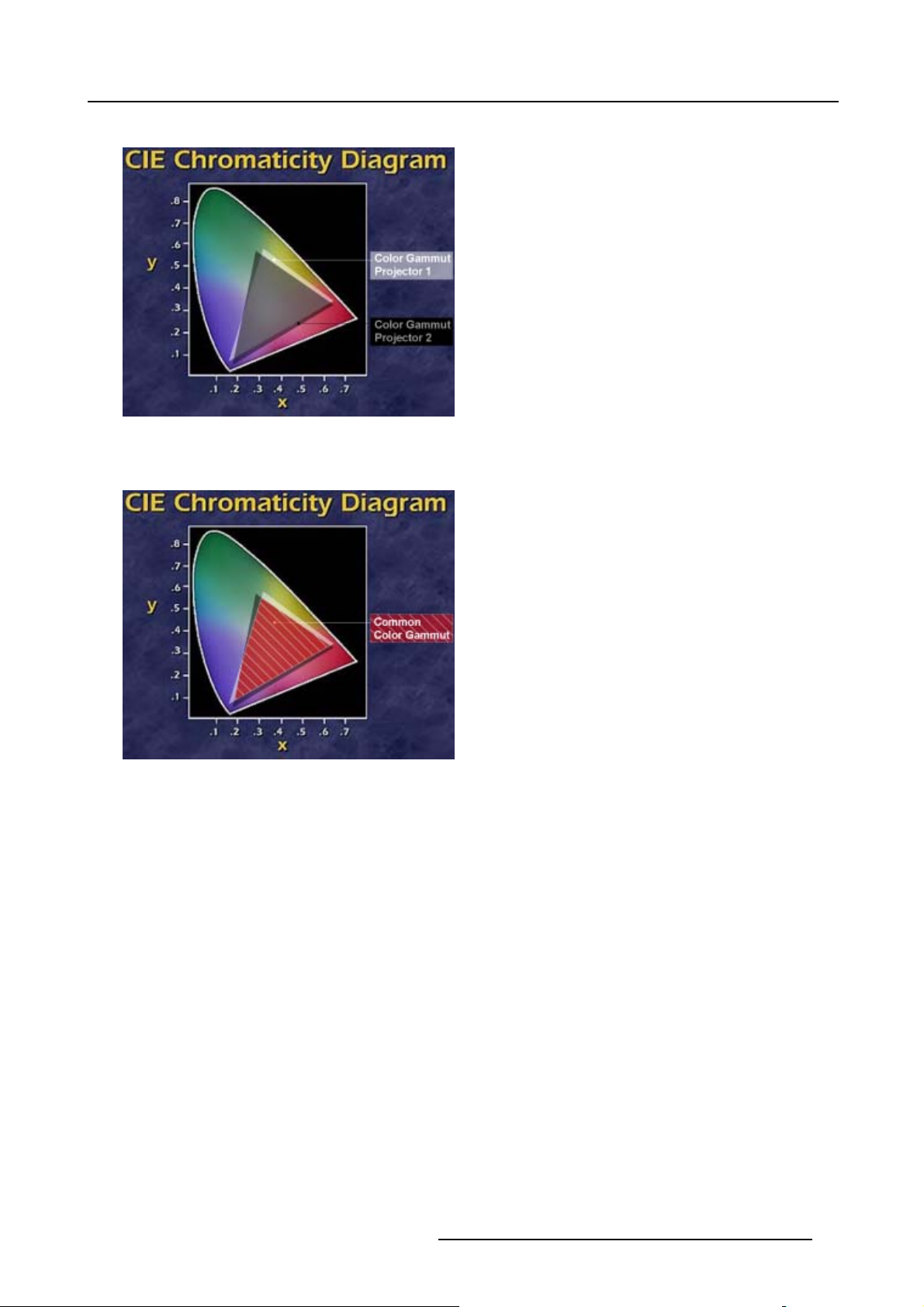
7. Image Menu
Due to the tolerance on optical components the x, y values of this color gamut of each projector will differ.
Image 7-16
The color gamut of each projector will differ
When working with a multichannel setup, these color differences between different projectors can be smooth out by matching the
color gamuts of the different projectors to a Common Color Gamut.
Image 7-17
Common Color Gamut
The Common Color Gamut
In a basic setup with 2 projectors, the perimeter of the Common Color Gamut is described by the 6 points of intersection of the 2
separate color gamuts.
R5976870 BARCOREALITY SIM 5PLUS/SIM 5R 04/04/2007 49
Page 54

7. Image Menu
.8
.7
.6
.5
G2
G1
Gc
y
.4
W1
.3
W2
Wc
Cc
.2
.1
Bc
Mc
B1
B2
0
.1 .2 .3 .4 .5 .6 .7
Yc
R2
Rc
x
Image 7-18
The Comm on Color Gamut
R1 Red projector 1
R2 Red projector 2
G1 Green Projector 1
G2 Green Projector 2
B1 Blue Projector 1
B2 Blue Projector 2
W1 White Projector 1
W2 White Projector 2
Rc Red Common Color Gamut
Gc Green Common Color Gamut
Bc Blue Common Color Gamut
Cc Cyan Common Color Gamut
Mc Magenta Common Color Gamut
Yc Yellow Common Color Gamut
Wc White Common Color Gamut
The following parameters can be adjusted within DynaColor™:
• the x, y coordinates and L(ight Output) of the 6 Common Color Gamut perimeter points.
• the x, y coordinat
es and L(ight Output) of the White point of the Common Color Gamut.
R1
How to Start up Dy
1. Press the MENU key to activate the Menu bar.
2. Push the cursor key ← or → to highlight Image in the menubar.
3. Push the ↓ key to pull down the Image menu.
4. Push the cursor key ↑ or ↓ to highlight Dynacolor and press ENTER to select. (image 7-19)
The Dynacolor dialog box will be displayed. (image 7-20)
50
nacolor™?
R5976870 BARCOREALITY SIM 5PLUS/SIM 5R 04/04/2007
Page 55

5. Push the cursor key ↑ or ↓ to highlight Status.
6. Press ENTER to toggle between enable or disable.
Image 7-19
7. Image Menu
Image 7-20
R5976870 BARCOREALITY SIM 5PLUS/SIM 5R 04/04/2007 51
Page 56

7. Image Menu
Dyancolor™ L (Light Output) Value
The value L in the Dyancolor™ interface represents a relative light output.
L=1 is the maximum available light output, the current CLO setting is taken into account.
Assume we have a projector, CLO is set to the desired value and assume the light output is x Lumens. L=1 in
the Dyancolor™ interface will correspond with a ’maximum full white light’ output of x Lumens.
Lmax will show the max available light output for each color.
Dynacolor™ Adjustment Preparations
Set the CLO setting to the same value for each projector involved in the Dynacolor™ Adjustment.
This to ensure that the L(ight Output) value is representing an equal Light Output level for each projector.
Two Dyancolor™ Sets
Two Dyancolor™ sets are available for each source file.
Each Dyancolor™ set will contain its own measured and desired parameters.
The first set can be used for a regular application, the second set can be used for a different optical setup e.g. an application with
Infitec filters, and this for the same source file.
The Dyancolor™ Interface
Following parameters are available in the Dyancolor™ Interface:
Measured Values These are the colors the projector displays when no color changes are made
Red x, y
Green x, y Coördinates for the Green point
Blue x, y
White x, y
White+ x, y
Red L Red Light output
Green L Green Light output
Blue L Blue Light output
White L
White+ L
Desired Values These are the colors you want the projector to display when the status is enabled
Red x, y
Green x, y Coördinates for the Green point
Blue x, y
Coördinates for the Red point
Coördinates for the Blue point
Coördinates for the White point
Coördinates for the Maximum White point
White Light Output = Red + Blue + Green Light output
Maximum Light Output = 1
Coördinates for the Red point
Coördinates for the Blue point
Cyan x, y Coördinates for the Cyan point
Ye llo w x, y
Magenta x, y
White x, y
Red L
Red Lmax
52 R5976870 BARCOREALITY SIM 5PLUS/SIM 5R 04/04/2007
Coördinates for the Yellow point
Coördinates for the Magenta point
Coördinates for the White point
Red Light Output
Maximum available Red Light Output
Page 57

Green L Green Light Output
Green Lmax Maximum available Green Light Output
7. Image Menu
Blue L
Blue Lmax
Cyan L Cyan Light Output
Cyan Lmax Maximum available Cyan Light Output
Ye llo w L
Yellow Lmax
Magenta L
Magenta Lmax
White L
White Lmax
Status
Toggle used Dynacolor™
Set
Factory Preset
Calibrate Measured
Values
Initialize Desired Values This will reset the desired parameters to no color change values.
Blue Light Output
Maximum available Blue Light Output
Yellow Light Output
Maximum available Yellow Light Output
Magenta Light Output
Maximum available Magenta Light Output
White Light Output
Maximum available White Light Output
Enables or disables Dynacolor™
2 Dynacolor™ sets are available for each custom source file, the selected set is saved in the
current file when leaving the menu. When creating a new file default set is 1.
Sets the measured parameters back to the factory preset for the current set
This start the calibration procedure for the measured points of the current set (Changing these
settings may seriously affect the performance of the projector).
White Boosting
This parameter (not adjustable) indicates the amount of white boosting for the current desired
Dynacolor™ values
Calibrate Measured Values
This will start the calibration procedure for the measured points of the current set (see "Calibrate Measured Values", page 229).
CAUTION: Changing the ’Calibrate Measured Values’ may seriously affect the performance of the projector.
Press the Factory Preset button to reset the ’Calibrate Measured Values’ to the factory preset.
Dynacolor™ ’Calculation in progress’ message
The message ’Calculation in progress! Please wait!’ is displayed in the top right corner of the dialog box when enabling/disabling
the Dynacolor™ status and when changing the desired values in the enabled status.
Dynacolor™ Adjustment in a Multi-Channel Setup (Linked Dynacolor™)
It is advised to use Barco’s xRACU control
unit to manage the ’linked’ Dynacolor™ of multiple projectors in a multi-channel setup.
Basic Dynacolor™ Adjustment
We assume we have a basic setup with 2 projectors, the Dynacolor™ adjustment is done by using only the Dynacolor™ menu:
1. Enable Dynacolor™ on both projectors.
2. Assume the first projector has the following measured values. (image 7-21)
3. Assume the second projector has the following measured values. (image 7-22)
4. We start by setting both projectors to the common red coordinate.
Tip: Draw a quick sketch of both gamuts as a graphical help. (image 7-23)
5. Display the internal color bar patter
6. In the desired values, adjust the red coordinate to a common value for both projectors.
Tip: The color barof the adjustedcoordinate will nolonger be displayedin case th e coordinate is not presentwithin the gamut
of the adjusted projector e.g. with the desired values for red set to x=660 and y= 318. (image 7-24)
nonbothprojectors.
R5976870 BARCOREALITY SIM 5PLUS/SIM 5R 04/04/2007
53
Page 58

7. Image Menu
Select a coordinate that is present in the common gamut e.g. with the desired values for red set to x=633 and y= 328. (image 7-25)
7. Repeat step 5 to 6 for all coordinates on both projectors.
Both projectors will now operate within the same color gamut.
Image 7-21
54 R5976870 BARCOREALITY SIM 5PLUS/SIM 5R 04/04/2007
Page 59

7. Image Menu
Image 7-22
R5976870 BARCOREALITY SIM 5PLUS/SIM 5R 04/04/2007 55
Page 60

7. Image Menu
330
320
310
R2
R1
650640
Image 7-23
Red coordinates for both projectors
330
320
310
650640
Image 7-24
Coordinate is not present within the gamut of the adjusted projector
660
R2
Rc
R1
660
56 R5976870 BARCOREALITY SIM 5PLUS/SIM 5R 04/04/2007
Page 61

330
320
310
7. Image Menu
R2
Rc
R1
650640
Image 7-25
Select a coordinate that is present in the common gamut
660
7.4 Infitec
How to activate Infitec?
1. Push the cursor key ↑ or ↓ to highlight Infitec.(image7-26)
2. Push the → key to pull down the Infitec menu.
A bullet will show the current Infitec status e.g. Off.
3. Push the cursor key ↑ or ↓ to highlight the desired Infitec status and press ENTER to select.
When In
Image 7-26
fitec is set to On the Infitec filter will be inserted into the light path of the projector.
7.5 Windowing
Overview
• Introduction
• Starting Up Windowing
•Blanking
•Shift
•Size
• Blanking – Softedge
R5976870 BARCOREALITY SIM 5PLUS/SIM 5R 04/04/2007
57
Page 62

7. Image Menu
7.5.1 Introduction
What can be done?
Within the Windowing menu it is possible to perform some basic image adjustments while keeping the pre-distorted WARP 6™
geometry settings of the image.
7.5.2 Starting Up Windowing
How to Start Up Windowing?
1. Push the cursor key ↑ or ↓ to highlight Windowing.
2. Push the → key to pull down the Windowing menu. (image 7-27)
Image 7-27
7.5.3 Blanking
What can be done with the Blanking Adjustment?
With the Blanking function it is possible to black out the side(s) of the image while keeping the pre-distorted WARP 6™ geometry
settings of the image.
How to use the Blanking Adjustment?
1. By default Blanking is already selected, press ENTER to select. (image 7-28)
The Blanking dialog box will be displayed. (image 7-29)
2. Use the cursor key ↑ or ↓ to select the desired side e.g. Top.
3. Use the cursor key ← or → , the numeric keys on the RCU, or the local keypad, to black out the side(s) of the image. (image 7-30)
Image 7-28
58 R5976870 BARCOREALITY SIM 5PLUS/SIM 5R 04/04/2007
Page 63

Image 7-29
7. Image Menu
Image 7-30
Blanking (Windowing) adjustment
7.5.4 Shift
What can be done with the Shift Adjustment?
With the Shift function it is possible to shift the image while keeping the pre-distorted WARP 6™ geometry settings of the image.
How to use the Shift Adjustment?
1. Push the cursor key ↑ or ↓ to highlight Shift and press ENTER to select. (image 7-31)
The Shift dialog box will be displayed. (image 7-32)
2. Use the cursor key ↑ or ↓ to select the Horizontal or Vertical shift direction.
R5976870 BARCOREALITY SIM 5PLUS/SIM 5R 04/04/2007
59
Page 64

7. Image Menu
3. Use the cursor key ← or → , the numeric keys on the RCU, or the local keypad, to shift the image to the desired position.
(image 7-33, image 7-34)
Image 7-31
Image 7-32
Image 7-33
Horizontal Shift Adjustment
Image 7-34
Vertical Shift Adjustment
60 R5976870 BARCOREALITY SIM 5PLUS/SIM 5R 04/04/2007
Page 65

7. Image Menu
7.5.5 Size
What can be done with Size?
With the Size function it is possible to adjust the size of the image while keeping the pre-distorted WARP 6™ geometry settings of
the image.
How to use the Size Adjustment?
1. Push the cursor key ↑ or ↓ to highlight Size and press ENTER to select. (image 7-35)
The Size dialog box will be displayed. (image 7-36)
2. Use the cursor key ↑ or ↓ to select the Horizontal or Vertical size.
3. Use the cursor key ← or → , the numeric keys on the RCU, or the local keypad, to change the size of the displayed image.
(image 7-37, image 7-38)
Image 7-35
Image 7-36
Image 7-37
Horizontal Size Adjustment
Image 7-38
Vertical Size Adjustment
R5976870 BARCOREALITY SIM 5PLUS/SIM 5R 04/04/2007 61
Page 66

7. Image Menu
7.5.6 Blanking – Softedge
What can be done with Blanking – Softedge?
When setting up a soft edge (see Electronic Softedge), these settings are by default applied on all sources (source files). With the
Blanking – Softedge toggle it is possible to disable the Blanking – Softedge settings for the current source file.
Blanking – Soft Edge is default set to On.
How to change the Blanking – Softedge Setting?
1. Push the cursor key ↑ or ↓ to highlight Blanking – Softedge and press ENTER to select.
The Blanking – Softedge Setting will be displayed. (image 7-39)
2. Use the cursor key ↑ or ↓ to select On or Off.
3. Press ENTER to confirm.
Image 7-39
7.6 Settings
Overview
• Introduction
• Contrast
• Brightness
• Gamma
• Phase
• Sharpness
7.6.1 Introduction
Introduction
Within the Settings menu it is possible to adjust the general image settings.
7.6.2 Contrast
It is advised not to use the Contrast Adjustment in a multi channel application.
How to use the Contrast Adjustment?
1. Push the cursor key ↑ or ↓ to highlight Contrast... and press ENTER to select. (image 7-40)
Note: The Contrast value is by default set to 100.
The Contrast Sliderbox will be displayed. (image 7-41)
62
R5976870 BARCOREALITY SIM 5PLUS/SIM 5R 04/04/2007
Page 67

2. Use the cursor keys ← or → or the numeric keys on the RCU to change the contrast of the displayed image.
Image 7-40
7. Image Menu
Image 7-41
7.6.3 Brightness
It is ad vised not to use the Brightness Adjustment in a multi channel application.
How to use the Brightness Adjustment?
1. Push the cursor key ↑ or ↓ to highlight Brightness and press ENTER to select. (image 7-42)
Note: The Brightness value is by default set to 0.
The Brightness Sliderbox will be displayed. (image 7-43)
2. Use the cursor keys ← or → or the numeric keys on the RCU to change the contrast of the displayed image.
Image 7-42
Image 7-43
R5976870 BARCOREALITY SIM 5PLUS/SIM 5R 04/04/2007 63
Page 68

7. Image Menu
7.6.4 Gamma
In a multi channel application it is advised to set the gamma values of all projectors to the same setting.
How to use the Gamma Adjustment?
1. Push the cursor key ↑ or ↓ to highlight Gamma and press ENTER to select. (image 7-44)
The Gamma Sliderbox will be displayed. (image 7-45)
2. Use the cursor keys ← or → or the numeric keys on the RCU to change the Gamma of the displayed image.
Image 7-44
Image 7-45
7.6.5 Phase
How to use the Phase Adjustment?
1. Push the
The Phase Sliderbox will be displayed. (image 7-47)
2. Use the cursor keys ← or → or the numeric keys on the RCU to change the Gamma of the displayed image.
cursor key ↑ or ↓ to highlight Phase and press ENTER to select. (image 7-46)
Image 7-46
64 R5976870 BARCOREALITY SIM 5PLUS/SIM 5R 04/04/2007
Page 69

Image 7-47
7.6.6 Sharpness
How to use the Sharpness Adjustment?
1. Push the cursor key ↑ or ↓ to highlight Sharpness and press ENTER to select. (image 7-48)
The Sharpness Sliderbox will be displayed. (image 7-49)
2. Use the cursor keys ← or → or the numeric keys on the RCU to change the Sharpness of the displayed image.
7. Image Menu
Image 7-48
49
Image 7-
7.7 Video
7.7.1 Tint (Hue)
How to use the Tint Adjustment?
1. Push the cursor key ↑ or ↓ to highlight Tint and press ENTER to select. (image 7-50)
The Tint Sliderbox will be displayed. (image 7-51)
2. Use the cursor keys ← or → or the numeric keys on the RCU to change the Tint of the displayed image.
R5976870 BARCOREALITY SIM 5PLUS/SIM 5R 04/04/2007
65
Page 70

7. Image Menu
Image 7-50
Image 7-51
7.7.2 Color
How to use the
1. Push the cursor key ↑ or ↓ to highlight Color and press ENTER to select. (image 7-52)
The Color Sliderbox will be displayed. (image 7-53)
2. Use the cursor keys ← or → or the numeric keys on the RCU to change the Color of the displayed image.
Image 7-52
Color Adjustment?
Image 7-53
7.7.3 AGC on video
AGC
Automatic Gain Control: Allows an automatic amplitude (gain) control of the incoming video signal.
66 R5976870 BARCOREALITY SIM 5PLUS/SIM 5R 04/04/2007
Page 71

AGC is only for video signals.
How use AGC on video?
1. Push the cursor key ↑ or ↓ to highlight AGC on video and press ENTER to continue. (image 7-54)
2. Push the → key to pull down the AGC on video menu.
A bullet will show the current AGC on video status e.g. On.
3. Push the cursor key ↑ or ↓ to enable or disable AGC.
7. Image Menu
Image 7-54
AGC can be disturbing in case of Macrovision encoded signals, therefore AGC can be disabled (Off) at any
time.
7.7.4 Manual Gain Control
Manual Gain Control is only available when Autom atic Gain C ontrol (AGC) is disabled.
What can be done?
Beside AGC there is the possibility to manually set the gain of the incoming video signal. When the AGC is enabled (On), the manual
setting does not affect the gain, AGC must therefore be disabled.
The manual gain control must be done on an external p
attern with white areas (Grey scale bar pattern).
How to set the Manual Gain Control?
1. Push the cursor key ↑ or ↓ to highlight Manual Gain Control and press ENTER to continue. (image 7-55)
The Manual Gain Control sliderbox will be displayed. (image 7-56)
2. Use the cursor keys ← or → or the numeric keys on the RCU to change the Manual Gain Control of the displayed image.
R5976870 BARCOREALITY SIM 5PLUS/SIM 5R 04/04/2007
67
Page 72

7. Image Menu
Image 7-55
Image 7-56
68 R5976870 BARCOREALITY SIM 5PLUS/SIM 5R 04/04/2007
Page 73

8. Geometry Menu
8. GEOMETRY MENU
Overview
• Introduction
• Geometry Menu Overview
• Geometry Files
• Load Geometry File
• Edit Geometry File
• Rename Geometry File
• Copy Geometry File
• Delete Geometry File
8.1 Introduction
What can be done with the WARP 6™ Geometry adjustments?
With the new WARP 6™ fitted in the BarcoReality SIM 5plus, fixed-matrix projectors can be used in a wide variety of c
applications, ranging from straightforward cylindrical displays to the wildest shapes that can be imagined: by pre-distorting the image
inside the projector, a correct geometry can be achieved on curved screens, without requiring additional computational power on
the IG’s side. Since WARP 6™ is integrated in the BarcoReality SIM 5plus Pixel Map Processor,
solution for even the most demanding applications.
Using the intuitive user interface, bows can be set up and modified in a flash, giving the user real-time access to the distortion
characteristics. For fine-tuning the image, the user has to access to individual grid points that can be shifted to their desired location.
it is an elegant and user-friendly
urved-screen
8.2 Geometry Menu Overview
Geometry Menu Overview
Geometry:
• Load
•Edit
-3x3
-5x5
-9x9
-17x17
-Shift
- Transport Delay
- Blanking / Softedge
o
Shape (Blanking)
o
Width
- Reset
o
Reset all levels
o
Restore 3x3
o
Restore 5x5
o
Restore 9x9
o
Restore Softedge Width
o
Reset Softedge All
o
Full Reset
• Rename
• Copy
• Delete
R5976870 BARCOREALITY SIM 5PLUS/SIM 5R 04/04/2007
69
Page 74

8. Geometry Menu
8.3 Geometry Files
What can be done?
Geometry settings are stored into geometry files, some geometry preset files are already available in the projector. These preset
files can be edited to the desired shape, these settings are automatically saved into an geometry custom file when leaving the Edit
menu.
Geometry File Notation
ThefilenotationintheGeometry files menu is built up in different parts. Let us have a look to these parts.
Take the following notation: xxxxxxxx.eee
xxxxxxxx
eee
Available Geometry Preset Fil
Following Geometry Preset Files Are available:
• t_nodist.t01 (No distortion)
es
base name, 8 characters
file extension:
first character t : geometry preset file.
first character g : geometry custom file.
The second and third character is used for a following number
(= file index). The file index range for custom files goes from
00 to 63.
Image 8-1
Geometry Preset: nodist
• t_zenith.t02
Image 8-2
Geometry Preset: zenith
70 R5976870 BARCOREALITY SIM 5PLUS/SIM 5R 04/04/2007
Page 75

• t_globe.t03
Image 8-3
Geometry Preset: globe
• t_sphear.t04
8. Geometry Menu
Image 8-4
Geometry Preset: sphear
R5976870 BARCOREALITY SIM 5PLUS/SIM 5R 04/04/2007 71
Page 76

8. Geometry Menu
• t_keystn.t05
Image 8-5
Geometry Preset: keystn
• t_fishey.t06
Image 8-6
Geometry Preset: fishey
Available Geometry File Manipulations
The following geometry file manipulations are possible:
• Load : load a geometry file or starting up a new geometry set up.
• Edit : editing a geometry file.
• Rename : renaming a geometry custom file.
• Copy : copying a geometry file.
• Delete : deleting a geometry custom file
8.4 Load Geometry File
What can be done?
This menu item is used to load any desired preset or custom geometry file.
How to Load a Geometry File?
1. Press the MENU key to activate the Menu bar.
2. Push the cursor key ← or → to highlight Geomet
3. Push the ↓ key to pull down the Ge ometry menu.
4. Push the cursor key ↑ or ↓ to highlight Load and press ENTER to select. (image 8-7)
The Load file dialogbox will be displayed. (image 8-8)
5. Use the cursor key ↑ and ↓ to select the desired geometry file and press ENTER to select.
Tip: When starting a new geometry setup it is advi
The file is loaded and the geometry settings are adapted.
ry in the menubar.
sed to select the “t_nodist.t01” file.
72
R5976870 BARCOREALITY SIM 5PLUS/SIM 5R 04/04/2007
Page 77

Image 8-7
8. Geometry Menu
Image 8-8
8.5 Edit Geometry File
Overview
• Introduction
• 3x3 Adjustment (Level 1-3)
• 5x5 Adjustment (Level 4-6)
•9x9Adj
• 17x17 Adjustment (Level 11-15)
•ShiftAdjustment
• Transport Delay
•Blanking
• Softedge
• Geometry Rese
ustment (Level 7-10)
t
R5976870 BARCOREALITY SIM 5PLUS/SIM 5R 04/04/2007
73
Page 78

8. Geometry Menu
8.5.1 Introduction
How does it work?
• The geometry adjustment is devided in 4 groups, representing 15 levels, each level represents a group of grid points, these
can be shifted to the desired location. Each level will interact with other levels in a hierarchic way, adjusting a grid point on a
certain hierarchic level will affect grid points in the levels underneath.
cornerLevel 1
3x3
5x5
9x9
17x17
Level 2
Level 3
Level 4
Level 5
Level 6
Level 7
Level 7
Level 8
Level 9
Level 10
Level 11
Level 11
Level 12
Level 13
side bow
center
H sideLevel 4
V side
center
quadrant
H side
V side
center
quadrant
fine
H side
V side
center
quadrant
Level 14
Level 15
Image 8-9
Overview hierarchic levels
fine
local
74 R5976870 BARCOREALITY SIM 5PLUS/SIM 5R 04/04/2007
Page 79

8. Geometry Menu
• This interaction is also visible in the adjustment menu, when selecting a grid point of a certain level, a selection box is placed
round the selected grid point, a second box with a dotted line will indicate the interaction zone on the levels underneath.
Selection Box
Interaction Box
Image 8-10
Selection Box + Interaction Box
• On top of this hierarchy is a matrix with 3 x 3 points, adjusting grid points on level 1 (corners) will affect level 2 till 15.
Level 1
Image 8-11
Level 1: 3x3 corner point
R5976870 BARCOREALITY SIM 5PLUS/SIM 5R 04/04/2007 75
Page 80

8. Geometry Menu
• At the bottom of the structure we find the matrix with 17 x 17 points, adjusting grid points on level 15 will not affect any other
grid points, these are called local points.
Level 15
Image 8-12
Level 15: 17x17 local point
• The best result is obtained by applying the geometry settings in the same hierarchic top to bottom order as listed in the menu
interface.
8.5.2 3x3 Adjustment (Level 1-3)
8.5.2.1 Starting up the 3x3 adjustment (Level 1-3)
How to Start up the 3x3 adjustment (Level 1-3)?
1. Press the MENU key to activate the Menu bar.
2. Push the cursor key ← or → to highlight Geometry i
3. Push the ↓ key to pull down the Ge ometry menu.
4. Push the cursor key ↑ or ↓ to to highlight Edit in the menubar.
5. Push the → key to pull down the Edit menu.
6. By default 3x3 and is selected, press ENTER to select. (image 8-13)
The Geometry Distortion dialogbox will be displayed. (image 8-14)
n the menubar.
Image 8-13
76 R5976870 BARCOREALITY SIM 5PLUS/SIM 5R 04/04/2007
Page 81

Image 8-14
8. Geometry Menu
Press the LOGO key on the RCU to switch b e tw een displaying the internal or external pattern.
8.5.2.2 Selecting the 3x3 Corners (Level 1)
What can be done?
With the 3x3 Corner selection it is possible to adjust the basic geometry and size of the projected image.
How t o selec t the 3x3 Corners (Level 1)?
1. By defa
2. Push the cursor key ← or → to select the desired Corner. (image 8-16)
ult corners is already selected, if not, press ENTER until corners is displayed. (image 8-15)
1
The COL & ROW (Column and Rows) indicator
will show the corresponding position of the selected Corner and an indication
box will be displayed on the screen.
Image 8-15
1. This
COL&ROW
indicates the position of the selected grid point within the 17 x 17 matrix.
R5976870 BARCOREALITY SIM 5PLUS/SIM 5R 04/04/2007 77
Page 82
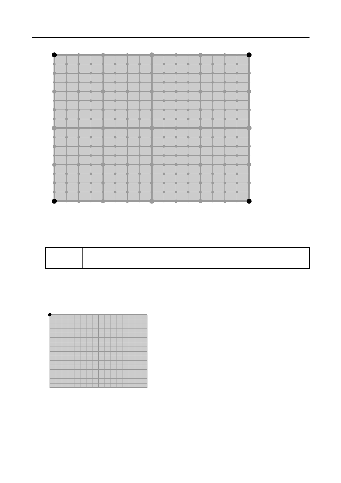
8. Geometry Menu
14
10
14
14
10
14
14
10
14
14
10
14
11
7
15
14
15
13
15
14
15
12
15
14
15
13
9
15
14
15
11
7
11
1
15
11
14
7 9
15
11
13
4
15
11
14
7
15
11
12
2
15
11
14
7
15
11
13
4
15
11
14
7
15
11
11
1
Image 8-16
3x3 Corner (Level 1) selections
12
12
12
12
12
12
12
12
11
2
15
14
8
15
13
5
15
14
8
15
12
3
15
14
8
15
13
5
15
14
8
15
11
2
11
4
15
13
14
15
13
13
6
15
13
14
9 9
15
13
12
5
15
13
14
9
15
13
13
6
15
13
14
9
15
13
11
4
11
7
15
14
14
10
15
14
13
99 9
15
14
14
10
15
14
12
88
15
14
14
10
15
14
13
15
14
14
10
15
14
11
7
14
10
14
14
10
14
14
10
14
14
10
14
11
7
15
14
15
13
9
15
14
15
12
15
14
15
13
99
15
14
15
11
7
13
13
13
13
13
13
13
13
14
10
14
14
10
14
14
10
14
14
10
14
11
7
88
9
7
15
14
15
13
15
14
15
12
15
14
15
13
15
14
15
11
1
11
7
11
4
11
7
11
2
11
7
11
4
11
7
11
1
11
4
15
14
9
15
13
6
15
14
15
12
5
15
14
9
15
13
6
15
14
9
15
11
4
8.5.2.3 Adjusting the 3x3 Corners (Level 1)
What is Pixel and Subpixel adjustment?
Pixel
Subpixel Fine tuning adjustment, this will shift the Corner in steps of 1/32 of a pixel
se adjustment, this will shift the Corner in steps of 1 pixel
Coar
What is AxisLink ?
When AxisLink is set to On, the adjustment coordinate system will coincide with the edges of the distorted image.
Following example will show a basic 3x3 corner adjustment with AxisLink On and Off.
1. Start with a non distorted image, assume the left top corner is selected.
0,0
Image 8-17
Non distorted image.
78 R5976870 BARCOREALITY SIM 5PLUS/SIM 5R 04/04/2007
Page 83

2. Shift the left top corner +300 pixels to the left.
300,0
X: +300
Image 8-18
Shift the left top corner 300 pixels to the left.
8. Geometry Menu
R5976870 BARCOREALITY SIM 5PLUS/SIM 5R 04/04/2007 79
Page 84

8. Geometry Menu
3. Shift the left corner +300 pixels downwards.
AxisLink [ON] The coordinate system used for the adjustment will coincide with the edges of the distorted image, this
AxisLink
[OFF]
will result in an quick adjustment when dealing with complex setups.
The coordinate system used for the adjustment is absolute.
AxisLink [OFF]AxisLink [ON]
X
Y
0
0
3
+
:
Y
225,300 300,300
Y
0
0
3
+
:
Y
X
X
X
Y
Image 8-19
Shift the left corner +300 pixels downwards
Y
How to adjust the 3x3 Corners (Level 1)?
1. Push the cursor key ↑ or ↓ to highlight the Pixels X edit box and press ENTER to select. (image 8-20)
2. Use the cursor key ← or → , the numeric keys on the RCU, or the local keypad, to edit and change the values, e.g. to coarse
shift the selected C
80
orner in a horizontal way. Press ENTER to confirm. (image 8-21)
R5976870 BARCOREALITY SIM 5PLUS/SIM 5R 04/04/2007
Page 85

8. Geometry Menu
3. Push the cursor key ↑ or ↓ to highlight the Pixels Y edit box and press ENTER to select.
4. Use the cursor key ← or → , the numeric keys on the RCU, or the local keypad, to edit and change the values, e.g. to coarse
shift the selected Corner in a vertical way (Follow this procedure in a similar way to adjust any desired corner position). Press
ENTER to confirm. (image 8-22)
Note: Apply this procedure to perform akeystone correction: this is used to align the imageif t he projector is mounted at anon
standard projector angle. (image 8-23)
5. Use the subpixel adjustments to fine shift the selected corners.
6. Press BACK to return to the Geometry Edit menu.
Image 8-20
Image 8-21
3x3 corner (Level 1) Pixel X adjustment
R5976870 BARCOREALITY SIM 5PLUS/SIM 5R 04/04/2007 81
Page 86

8. Geometry Menu
Image 8-22
3x3 corner (Level 1) PixelY adjustment
Image 8-23
Keystone correction
8.5.2.4 Selecting the 3x3 Side Bows (Level 2)
What can be done?
With the 3x3 Side Bow selection it is possible to:
• apply a bow shaped pre-distortion on the projected image.
• perform a coarse linearity adjustment off the projected image.
How to select the 3x3 Side Bows (Level 2)?
1. Push the cursor key ↑ or ↓ to highlight the 3x3 selection box.
82
R5976870 BARCOREALITY SIM 5PLUS/SIM 5R 04/04/2007
Page 87

8. Geometry Menu
2. Press ENTER to scroll through the available 3x3 selections until side bows is displayed. (image 8-24)
3. Push the cursor key ← or → to select the desired Side Bow. (image 8-25)
The COL & ROW (Column and Rows) indicator will show the corresponding position of the selected Side Bow and an indication
box will be displayed on the screen.
Image 8-24
14
10
14
14
10
14
14
10
14
14
10
14
11
7
15
14
15
13
15
14
15
12
15
14
15
13
9
15
14
15
11
7
11
1
15
11
14
7 9
15
11
13
4
15
11
14
7
15
11
12
2
15
11
14
7
15
11
13
4
15
11
14
7
15
11
11
1
Image 8-25
3x3 Side Bow (Level 2) selections
12
12
12
12
12
12
12
12
11
2
15
14
8
15
13
5
15
14
8
15
12
3
15
14
8
15
13
5
15
14
8
15
11
2
11
4
15
13
14
15
13
13
6
15
13
14
9 9
15
13
12
5
15
13
14
9
15
13
13
6
15
13
14
9
15
13
11
4
11
7
15
14
14
10
15
14
13
99 9
15
14
14
10
15
14
12
88
15
14
14
10
15
14
13
15
14
14
10
15
14
11
7
14
10
14
14
10
14
14
10
14
14
10
14
11
7
15
14
15
13
9
15
14
15
12
15
14
15
13
99
15
14
15
11
7
13
13
13
13
13
13
13
13
14
10
14
14
10
14
14
10
14
14
10
14
11
7
88
9
7
15
14
15
13
15
14
15
12
15
14
15
13
15
14
15
11
1
11
7
11
4
11
7
11
2
11
7
11
4
11
7
11
1
11
4
15
14
9
15
13
6
15
14
15
12
5
15
14
9
15
13
6
15
14
9
15
11
4
8.5.2.5 Setting up a bow shaped pre-distortion
How to set up a bow shaped pre-distortion?
We assume the side bow on top is selected.
1. Push the cursor key ↑ or ↓ to highlight the Pixels Y edit box and press ENTER to select. (image 8-26)
2. Use the cursor key ← or → , the numeric keys on the RCU, or the local keypad, to edit and change the values, e.g. to coarse
shift the selected Side Bow in a vertical way. Press ENTER to confirm.
R5976870 BARCOREALITY SIM 5PLUS/SIM 5R 04/04/2007
83
Page 88

8. Geometry Menu
This will result in a bow shaped pre-distorted image (Follow this procedure in a similar way to apply the desired bow shaped
distortion). (image 8-27)
3. Use the subpixel adjustments to fine shift the selected Side Bows.
4. Press BACK to return to the Geometry Edit menu.
Image 8-26
Image 8-27
Bow shaped pre-distortions
84 R5976870 BARCOREALITY SIM 5PLUS/SIM 5R 04/04/2007
Page 89

8. Geometry Menu
8.5.2.6 Linearity adjustment using 3x3 Side Bows
The Linearity adju stment is best done when a reference test pattern is projected on the screen.
How to perform a linearity adjustment by using the 3x3 Side Bows?
We assume the side bow on top is selected.
1. Push the cursor key ↑ or ↓ to highlight the Pixels X edit box and press ENTER to select. (image 8-28)
2. Use the cursor key ← or → , the numeric keys on the RCU, or the local keypad, to edit and change the values, e.g. to coarse
shift the selected Side Bow in a horizontal way. Press ENTER to continue.
3. Repeat step 1 to 2 for the 3x3 side bow selection on the bottom.
This will shift the vertical center line, resulting in a coarse horizontal linearity adjustment (Follow this procedure in a similar way
to shift the horizontal center line). (image 8-29)
4. Use the subpixel adjustments to fine shift the selected Side Bows.
5. Press BACK to return to the Geometry Edit menu.
Image 8-28
R5976870 BARCOREALITY SIM 5PLUS/SIM 5R 04/04/2007 85
Page 90

8. Geometry Menu
Image 8-29
Using side bows to perform a coarse linearity adjustment
8.5.2.7 Selecting the Center (Level 3)
What can be done?
With the 3x3 Center selection it is possible to perform a coarse bow correction on the projected image.
How to select the 3x3 Center?
1. Push the cursor key ↑ or ↓ to highlight the 3x3 selection box.
2. Press ENTER to scroll through the available 3x3 selections until center is displayed. (image 8-30, image 8-31)
The COL & ROW (Column and Rows) indicator will show the corresponding position of the selected Center and an indication box
will be displayed on the screen.
86
R5976870 BARCOREALITY SIM 5PLUS/SIM 5R 04/04/2007
Page 91

Image 8-30
8. Geometry Menu
14
10
14
14
10
14
14
10
14
14
10
14
11
7
15
14
15
13
15
14
15
12
15
14
15
13
9
15
14
15
11
7
11
1
15
11
14
7 9
15
11
13
4
15
11
14
7
15
11
12
2
15
11
14
7
15
11
13
4
15
11
14
7
15
11
11
1
Image 8-31
3x3 Center (Level 3) selections
12
12
12
12
12
12
12
12
11
2
15
14
8
15
13
5
15
14
8
15
12
3
15
14
8
15
13
5
15
14
8
15
11
2
11
4
15
13
14
15
13
13
6
15
13
14
9 9
15
13
12
5
15
13
14
9
15
13
13
6
15
13
14
9
15
13
11
4
11
7
15
14
14
10
15
14
13
99 9
15
14
14
10
15
14
12
88
15
14
14
10
15
14
13
15
14
14
10
15
14
11
7
14
10
14
14
10
14
14
10
14
14
10
14
11
7
15
14
15
13
9
15
14
15
12
15
14
15
13
99
15
14
15
11
7
13
13
13
13
13
13
13
13
14
10
14
14
10
14
14
10
14
14
10
14
11
7
88
9
7
15
14
15
13
15
14
15
12
15
14
15
13
15
14
15
11
1
11
7
11
4
11
7
11
2
11
7
11
4
11
7
11
1
11
4
15
14
9
15
13
6
15
14
15
12
5
15
14
9
15
13
6
15
14
9
15
11
4
8.5.2.8 Adjusting the 3x3 Center (Level 3)
How to adjust the 3x3 Center (Level 3)?
1. Push the cursor key ↑ or ↓ to highlight the Pixels X edit box and press ENTER to select. (image 8-32)
2. Use the cursor key ← or → , the numeric keys on the RCU, or the local keypad, to edit and change the values, e.g. to coarse
shift the Center in a horizontal way. Press ENTER to continue. (image 8-33)
3. Push the cursor key ↑ or ↓ to highlight the Pixels Y edit box and press ENTER to select.
4. Use the cursor key ← or → , the numeric keys on the RCU, or the local keypad, to edit and change the values, e.g. to coarse
shift the Center in a vertical way. Press ENTER to continue. (image 8-34)
5. Use the subpixel adjustments to fine shift the Center.
R5976870 BARCOREALITY SIM 5PLUS/SIM 5R 04/04/2007
87
Page 92

8. Geometry Menu
6. Press BACK to return to the Geometry Edit menu.
Image 8-32
Image 8-33
3x3 corner (Level 3) Pixel X adjustment
88 R5976870 BARCOREALITY SIM 5PLUS/SIM 5R 04/04/2007
Page 93

8. Geometry Menu
Image 8-34
3x3 corner (Level 3) Pixel Y adjustment
8.5.3 5x5 Adjustment (Level 4-6)
Overview
• Starting Up the 5x5 Adjustment (Level 4-6)
• Selecting the 5x5 H-side (Level 4)
•Adjust
• Selecting the 5x5 V-side (Level 4)
• Adjusting the 5x5 V-side (Level 4)
• Selecting the 5x5 Center (Level 5)
• Adjusting the 5x5 Center (Level 5)
• Selecting the 5x5 Quadrant (Level 6)
• Adjusting the 5
ingthe5x5H-side(Level4)
x5 Quadrant (Level 6)
8.5.3.1 Starting Up the 5x5 Adjustment (Level 4-6)
What can be done?
While the previous 3x3 adjustments are used to shape the basic geometry , the 5x5 adjustments will allow geometry adjustments at
a medium level.
How to Start up the 5x5 adjustment (Level 4-6)?
1. Press the MENU key to activate the Menu bar.
2. Push the cursor key ← or → to highlight Geometry in the menubar.
3. Push the ↓ key to pull down the Ge ometry menu.
4. Push the cursor key ↑ or ↓ to to highlight Edit in the menubar.
5. Push the → key
6. Push the cursor key ↑ or ↓ to highlight 5x5 and press ENTER to select. (image 8-35)
The Geometry Distortion dialogbox will be displayed. (image 8-36)
to pull down the Edit menu.
R5976870 BARCOREALITY SIM 5PLUS/SIM 5R 04/04/2007
89
Page 94

8. Geometry Menu
Image 8-35
Image 8-36
8.5.3.2 Selecting the 5x5 H-side (Level 4)
What can be done?
This adjustment can be used to correct e.g. the vertical nonlinearity in the left or right half of the screen.
The Linearity adjustment is best done when a hatch pattern is projected on the screen.
How to select the 5x5 H-side (Level 4)?
1. By default H-side is already selected, if not, press ENTER until H-side is displayed. (image 8-37)
2. Push the cursor key ← or → to select the desired H-side. (image 8-38)
The COL& ROW (Column and Rows) indicator will show the corresponding position of the selected H-side and an indication box
will be displayed on the screen.
90
R5976870 BARCOREALITY SIM 5PLUS/SIM 5R 04/04/2007
Page 95

Image 8-37
8. Geometry Menu
14
10
14
14
10
14
14
10
14
14
10
14
11
7
15
14
15
13
15
14
15
12
15
14
15
13
9
15
14
15
11
7
11
1
15
11
14
7 9
15
11
13
4
15
11
14
7
15
11
12
2
15
11
14
7
15
11
13
4
15
11
14
7
15
11
11
1
Image 8-38
5x5 H-side (Level 4) selections
12
12
12
12
12
12
12
12
11
2
15
14
8
15
13
5
15
14
8
15
12
3
15
14
8
15
13
5
15
14
8
15
11
2
11
4
15
13
14
15
13
13
6
15
13
14
9 9
15
13
12
5
15
13
14
9
15
13
13
6
15
13
14
9
15
13
11
4
11
7
15
14
14
10
15
14
13
99 9
15
14
14
10
15
14
12
88
15
14
14
10
15
14
13
15
14
14
10
15
14
11
7
14
10
14
14
10
14
14
10
14
14
10
14
11
7
15
14
15
13
9
15
14
15
12
15
14
15
13
99
15
14
15
11
7
13
13
13
13
13
13
13
13
14
10
14
14
10
14
14
10
14
14
10
14
11
7
88
9
7
15
14
15
13
15
14
15
12
15
14
15
13
15
14
15
11
1
11
7
11
4
11
7
11
2
11
7
11
4
11
7
11
1
11
4
15
14
9
15
13
6
15
14
15
12
5
15
14
9
15
13
6
15
14
9
15
11
4
8.5.3.3 Adjusting the 5x5 H-side (Level 4)
How to adjust the 5x5 H-side (Level 4)?
1. Push the cursor key ↑ or ↓ to highlight the Pixels X edit box and press ENTER to select. (image 8-39)
2. Use the cursor key ← or → , the numeric keys on the RCU, or the local keypad, to edit and change the values, e.g. to coarse
shift the selected H-side in a horizontal way. Press ENTER to confirm. (image 8-40)
3. Push the cursor key ↑ or ↓ to highlight the Pixels Y edit box and press ENTER to select.
4. Use the cursor key ← or → , the numeric keys on the RCU, or the local keypad, to edit and change the values, e.g. to coarse
shift the selected H-side in a vertical way (Follow this procedure in a similar way to adjust any desired H-side position). Press
ENTER to confirm. (image 8-41)
5. Use the subpixel adjustments to fine shift the selected H-side.
R5976870 BARCOREALITY SIM 5PLUS/SIM 5R 04/04/2007
91
Page 96

8. Geometry Menu
6. Press BACK to return to the Geometry Edit menu.
Image 8-39
Image 8-40
5x5 H side (Level 4) Pixel X adju
stment
92 R5976870 BARCOREALITY SIM 5PLUS/SIM 5R 04/04/2007
Page 97

8. Geometry Menu
Image 8-41
5x5 H side (Level 4) Pixel Y adjustment
8.5.3.4 Selecting the 5x5 V-side (Level 4)
What can be done?
s adjustment can be used to correct e.g. the horizontal nonlinearity in the upper or lower half of the screen.
Thi
to select the 5x5 V-side (Level 4)?
How
1. Push the cursor key ↑ or ↓ to highlight the 5x5 selection box.
2. Press ENTER to scroll through the available 5x5 selections until V-side is displayed. (image 8-42)
3. Push the cursor key ← or → to select the desired V-side. (image 8-43)
The COL & ROW (Column and Rows) indicator will show the corresponding position of the selected V-side and an indication box
be displayed on the screen.
will
Image 8-42
R5976870 BARCOREALITY SIM 5PLUS/SIM 5R 04/04/2007 93
Page 98

8. Geometry Menu
14
10
14
14
10
14
14
10
14
14
10
14
11
7
15
14
15
13
15
14
15
12
15
14
15
13
9
15
14
15
11
7
11
1
15
11
14
7 9
15
11
13
4
15
11
14
7
15
11
12
2
15
11
14
7
15
11
13
4
15
11
14
7
15
11
11
1
Image 8-43
5x5 V-side (Level 4) selections
12
12
12
12
12
12
12
12
11
2
15
14
8
15
13
5
15
14
8
15
12
3
15
14
8
15
13
5
15
14
8
15
11
2
11
4
15
13
14
15
13
13
6
15
13
14
9 9
15
13
12
5
15
13
14
9
15
13
13
6
15
13
14
9
15
13
11
4
11
7
15
14
14
10
15
14
13
99 9
15
14
14
10
15
14
12
88
15
14
14
10
15
14
13
15
14
14
10
15
14
11
7
14
10
14
14
10
14
14
10
14
14
10
14
11
7
15
14
15
13
9
15
14
15
12
15
14
15
13
99
15
14
15
11
7
13
13
13
13
13
13
13
13
14
10
14
14
10
14
14
10
14
14
10
14
11
7
88
9
7
15
14
15
13
15
14
15
12
15
14
15
13
15
14
15
11
1
11
7
11
4
11
7
11
2
11
7
11
4
11
7
11
1
11
4
15
14
9
15
13
6
15
14
15
12
5
15
14
9
15
13
6
15
14
9
15
11
4
8.5.3.5 Adjusting the 5x5 V-side (Level 4)
How to adjust the 5x5 V-side (Level 4)?
1. Push the cursor key ↑ or ↓ to highlight the Pixels X edit box and press ENTER to select. (image 8-44)
2. Use the cursor key ← or → , the numeric keys on the RCU, or the local keypad, to edit and change the values, e.g. to coarse
shift the selected V-side in a horizontal way. Press ENTER to continue. (image 8-45)
3. Push the cursor key ↑ or ↓ to highlight the Pixels Y edit box and press ENTER to select.
4. Use the cursor key ← or → , the numeric keys on the RCU, or the local keypad, to edit and change the values, e.g. to coarse
shift the selected V-side in a vertical way (Follow this procedure in a similar way to adjust any desired V-side position). Press
ENTER to continue. (image 8-46)
5. Use the subpixel adjustments to fine shift the selected V-side.
6. Press BACK to return to the Geometry Edit menu.
94
R5976870 BARCOREALITY SIM 5PLUS/SIM 5R 04/04/2007
Page 99

Image 8-44
8. Geometry Menu
Image 8-45
5x5 V side (Level 4) Pixel X adjustment
R5976870 BARCOREALITY SIM 5PLUS/SIM 5R 04/04/2007 95
Page 100

8. Geometry Menu
Image 8-46
5x5 V side (Level 4) Pixel X adjustment
8.5.3.6 Selecting the 5x5 Center (Level 5)
How to select the 5x5 Center (Level 5)?
1. Push
2. Press ENTER to scroll through the available 5x5 selections until Center is displayed. (image 8-47)
3. Push the cursor key ← or → to select the desired Center. (image 8-48)
the cursor key ↑ or ↓ to highlight the 5x5 selection box.
The COL & ROW (Column and Rows) indicator will show the corresponding position of the selected V-side and an indication box
will be displayed on the screen.
Image 8-47
96 R5976870 BARCOREALITY SIM 5PLUS/SIM 5R 04/04/2007
 Loading...