

Page 1

E2
User’s guide
R5905948/00
12/12/2014
Page 2

Barco Inc, Image Processing
3078 Prospect Park Drive, Rancho Cordova, CA , 95670, USA
Phone: +1 916 859-2500
Fax: +1 916 859-2515
Support: www.barco.com/esupport
Visit us at the web: www.barco.com
Printed in USA
Page 3

Changes
Barco provides this manual ’as is’ w ithout warranty of any kind, either expressed or implied, including but not limited to the implied warranties or merchantability and fitness for a particular purpose. Barco may make improvements and/or changes to the product(s) and/or the
program(s) described in this publication at any time without notice.
This publication could contain technical inaccuracies or typographical errors. Changes are periodically made to the information in this
publication; these changes are incorporated in new editions of this publication.
The latest edition of Barco manuals can be downloaded from the Barco web site w
h
ttps://www.barco.com/en/signin.
ww.barco.com or from the secured Barco web site
Copyright ©
All rights reserved. No part of this document may be copied, reproduced or translated. It shall not otherwise be recorded, transmitted or
stored in a retrieval system without the prior written consent of Barco.
Guarantee and Compensation
Barco provides a guarantee relating to perfect manufacturing as part of the legally stipulated terms of guarantee. O n re ceipt, the pu rchaser
must immediately inspect all delivered goods for damage incurred during transport, as well as for material and manufacturing faults Barco
must be informed immediately in writing of any complaints.
The period of guarantee begins on the date of transfer of risks, in the case of spec ial systems and software on the date of commissioning,
at latest 30 days after the transfer of risks. In the event of justified notice of complaint, Barco can repair the fault or provide a replacement
at its own discretion within an appropriate period. If this measure proves to be impossible or unsuccessful, the purchaser ca n demand a
reduction in the purchase price or cancellation of the contract. All other claims, in particular those relating to compensation for direct or
indirect damage, and also da mage attributed to the operation of s oftware as well as to other services provided by Barco, being a component
of the s ystem or independent service, will be deemed invalid provided the damage is not proven to be attributed to the absence of properties
guaranteed in writing or due to the intent or gross negligence or part of Barco.
If the purchaser or a third party carries out modifications or rep
in particular if the systems are operated incorrectly or if, after the t ransfer of risks, the goods are subject to influences not agreed upon in
the contract, all guarantee claims of the purchaser will be rendered invalid. Not included in the guarantee coverage are system failures
which are attributed to programs or special electronic cir
maintenance a re not subject to the guarantee provided by Barco either.
The environmental conditions as well as the servicing and maintenance regulations specified in this manual must be complied with by the
customer.
airs o n goods delivered by Barco, or if the goods are handled inc orrectly,
cuitry provided by the purchaser, e.g. interfaces. Normal wear as well a s normal
Trademarks
Brand and product names mentioned in this m anual may be trademarks, registered trademarks or copyrights of their respective holders.
All brand and product n ames mentioned in this manual serve as comments or ex amples and are not to be understood as advertising for
the products or their manufacturers.
Software License Agreement
You should carefully read the following terms and conditions before using this software. Your use of this software indicates your acceptance
of this license agreement and warranty.
Terms and Conditions:
1. No redistribution of the software is allowed.
2. Reverse-Engineering. You may not reverse engineer, decompile, disassemble or alter this software product.
Disclaimer of Warranty:
This software and the a ccom panying files are sold “as is” and without warranties as to performance or merchantability or any other warranties whether expressed or implied. In no ev ent shall Barco be liable for damage of any kind, loss of data, loss of profits, business
interruption or other pecuniary loss aris
product or refund of purchase price.
ing directly or indirectly. Any liability of the seller will be exclusively limited to replacement of the
Federal Communications Commission (FCC Statement)
This equipment has been tested and found to comply with t he limits for a class A digital device, pursuant to Part 15 of the FCC rules.
These limits are designed to provide reasonable protection aga inst harmful interference when the equipment is operated in a commercial
environment. This equipment generates, uses, and can radiate radio frequency energy and, if not installed and used in a ccordance with
the instruction manual, may cause harmful interference to radio communications. Operation of this equipm ent in a residential area may
cause harmful interference, in which case the user will be responsible for correcting any interference at his own ex pense
Page 4

Changes or modifications not expressly approved by the party responsible for compliance could void the user’s authority to operate the
equipment
EN55032/CISPR32 Class A Multimedia Equipment
Warning : This equipm ent is compliant with Class A of CISPR 32. In a residential environment this equipment may cause radio interfer-
ence.
Page 5

Table of contents
TABLE OF CON TENTS
1. Introduction ............... ................ ................ ................ ................ ................ .......... 5
1.1 About this guide ...................................................................................................................... 6
1.2 Symbols, pictures and fonts .......................................................................................................... 7
1.3 The 4K screen management system E2 . . . . ......................................................................................... 8
2. Safety................................................................................................................. 9
2.1 General considerations .............................................................................................................. 10
2.2 Important safety instructions ........................................................................................................ 11
3. General....... ................ ................ ................ ................ ................ ................ .......13
3.1 E2 overview.......................................................................................................................... 14
3.2 Features ............................................................................................................................. 15
3.3 Terms and definitions................................................................................................................ 18
3.4 Control overview.....................................................................................................................21
3.5 Presentation System overview ......................................................................................................22
3.6 Installation requirements . . . .........................................................................................................23
3.7 Initial inspection...................................................................................................................... 24
3.8 E2 Rack-Mount Procedure . .........................................................................................................25
4. Hardware orientation .............................................................................................29
4.1 Front panel. . . ........................................................................................................................ 30
4.2 Rear panel . . . ........................................................................................................................32
4.3 6G SDI Input Card . . .................................................................................................................35
4.4 Dual Link DVI Input Card . . ..........................................................................................................37
4.5 HDMI/DisplayPort Input Card .......................................................................................................39
4.6 HDMI Output Card...................................................................................................................41
4.7 6G SDI Output Card.................................................................................................................42
4.8 Expansion link card. .................................................................................................................44
5. Front Panel Menu orientation .. ................ ................ ................ ................ ................ .45
5.1 Power-up initialization............................................................................................................... 46
5.2 E2 Front Panel menu tree. . ......................................................................................................... 47
5.3 Using menu system ................................................................................................................. 48
5.4 About Status menu.................................................................................................................. 50
5.5 About Setup menu...................................................................................................................51
5.6 About the System menu .............................................................................................................52
5.7 System menu > Black Invalid .......................................................................................................53
5.8 System menu > USB device (Backup/Restore) . ...................................................................................54
5.9 System menu > Ethernet .. . ......................................................................................................... 56
5.10 System menu > VFD brightness (display brightness) . . . ........................................................................... 58
5.11 System menu > Diagnostics ........................................................................................................ 59
5.12 System menu > Lock front panel. ...................................................................................................62
5.13 Using the Tech Support menu.......................................................................................................63
5.14 Restoring Factory Default Settings .................................................................................................64
5.15 Firmware Upgrade...................................................................................................................65
5.16 Save All.............................................................................................................................. 66
6. GUI orientation.......... ................ ................ ................ ................ ................ ...........67
6.1 General requirements ...............................................................................................................69
6.2 Download of EventMaster Control Software ....................................................................................... 70
6.3 Software installation ................................................................................................................. 71
6.4 Starting up ...........................................................................................................................72
6.5 Screen layout presentation..........................................................................................................73
6.6 Controls ..............................................................................................................................75
6.7 Configuration Menu..................................................................................................................76
6.8 Configuration Menu > Device area..................................................................................................77
6.9 Configuration Menu > System diagram area ....................................................................................... 79
6.10 Configuration M enu > System modifier area ....................................................................................... 81
6.11 Configuration Menu > Adjustment area.............................................................................................82
6.12 Configuration M enu > Adjustment > Unit Configuration............................................................................ 83
6.13 Configuration M enu > Adjustment > Input Configuration...........................................................................84
6.14 Configuration M enu > Adjustment > Background Configuration...................................................................91
6.15 Configuration M enu > Adjustment > Output Configuration......................................................................... 92
6.16 Configuration M enu > Adjustment > Destination Configuration....................................................................99
6.17 Programming Menu ................................................................................................................105
6.18 Programming Menu > Sources area ...............................................................................................106
6.19 Programming Menu > Diagram area...............................................................................................112
6.20 Programming Menu > Layer Modifier area ........................................................................................115
6.21 Programming Menu > Adjustment area. . . . . .......................................................................................119
6.22 Programming Menu > Adjustment area > Layer configuration....................................................................120
6.23 Programming Menu > Adjustment area > Background configuration.............................................................126
6.24 Programming Menu > Adjustment area > User keys configuration...............................................................128
6.25 Programming Menu > Adjustment area > Presets configuration .................................................................130
R5905948 E2 12/12/2014
1
Page 6

Table of contents
6.26 Programming Menu > Adjustment area > Source adjustment . ...................................................................131
6.27 Programming Menu > Adjustment area > Global Transition Rate/Trans/Cut. ....................................................133
6.28 Multiviewer(MVR) Menu ...........................................................................................................134
6.29 MultiviewerMenu > Resource area................................................................................................135
6.30 MultiviewerMenu > Multiviewer Layout area......................................................................................136
6.31 Multiviewer Menu > Modifier area..................................................................................................138
6.32 MultiviewerMenu > Adjustmentarea ..............................................................................................139
6.33 MultiviewerMenu > Adjustmentarea > Output Color .............................................................................140
6.34 Multiviewer Menu > Adjustment area > Window adjustment. .. ...................................................................141
6.35 Settings Menu ......................................................................................................................142
6.36 Settings Menu > WebKitarea ...................................................................................................... 144
6.37 Settings Menu > WebKitarea > Dashboard .......................................................................................145
6.38 Settings Menu > WebKitarea > Tools .............................................................................................149
6.39 Settings Menu > WebKit ar ea > Tools > Manage Software .......................................................................150
6.40 Settings Menu > WebKitarea > Tools > Backup & Restore ......................................................................152
6.41 Settings Menu > WebKitarea > Help..............................................................................................154
6.42 Settings Menu > WebKitarea > Contactus .......................................................................................155
6.43 Settings Menu > WebKitarea > Follow us.........................................................................................156
7. System Setup ... ................ ................ ................ ................ ................ ................ . 157
7.1 Setup Prerequisites . ................................................................................................................158
7.2 System setup sequence ............................................................................................................159
7.3 Power up and Status check........................................................................................................160
7.4 Return to factory default............................................................................................................161
7.5 Communication setup ..............................................................................................................162
7.6 Restoring the system...............................................................................................................163
7.7 User preference setup..............................................................................................................164
7.8 Savingthe setup....................................................................................................................165
7.9 Backing up the system .............................................................................................................166
7.10 Configuration Menu > InitialSetup ................................................................................................167
7.11 Configuration Menu > Add Background(s).........................................................................................168
7.12 Configuration Menu > Add Inputs..................................................................................................169
7.13 Configuration Menu > Add Outputs................................................................................................170
7.14 Configuration Menu > Add Screen Destinations & Layers........................................................................171
7.15 Configuration Menu > Add Aux Destinations ......................................................................................172
7.16 Configuration Menu > Add MVR Outputs..........................................................................................173
7.17 Programming Menu > Select Thumbnails for Backgrounds . . . ...................................................................174
7.18 Programming Menu > Select Thumbnails for Inputs ..............................................................................175
7.19 Programming Menu > Create Sources from Inputs ...............................................................................176
7.20 Programming Menu > Drop backgrounds into Screen Destinations . . . ...........................................................177
7.21 Programming Menu > Drop Layers into Screen Destinations & Sources into layers ............................................178
7.22 Programming Menu > Drop Inputs to Aux Destinations. ..........................................................................180
7.23 Multiviewer Menu > Drop Inputs, Backgrounds and Destinations ................................................................181
8. Updating firmware............ ................ ................ ................ .................. ................ . 183
8.1 Upgrading firmware using the USB port ...........................................................................................184
8.2 Upgrading firmware using the web Upgrade ......................................................................................186
9. General operation example.................................................................................... 189
9.1 Event requirements . ................................................................................................................190
9.2 Preliminary..........................................................................................................................191
9.3 Control Software Operation ........................................................................................................193
9.4 Configuration Menu.................................................................................................................194
9.5 Programming Menu ................................................................................................................199
9.6 Multiviewer (MRV) Menu .. . ........................................................................................................210
10. Maintenance...................................................................................................... 213
10.1 E2 unit Overview ...................................................................................................................215
10.2 Process Overview ..................................................................................................................216
10.3 Spare Parts Serviceable by all users ..............................................................................................217
10.4 Rear I/O and Link Cards ...........................................................................................................218
10.5 Rear I/O, VPU andLink card Heatsink Fan .......................................................................................220
10.6 Front Cover Assembly..............................................................................................................221
10.7 Front Brackets ......................................................................................................................224
10.8 EMI Filter............................................................................................................................225
10.9 3RU Fan Tray.......................................................................................................................226
10.10 1RU Fan Tray.......................................................................................................................227
10.11 VPU Card(s)........................................................................................................................229
10.12 Front Panel Knob...................................................................................................................230
10.13 Front Panel Mount .................................................................................................................232
10.14 Front Panel Board .................................................................................................................233
10.15 VFD Display Assembly.............................................................................................................235
10.16 VFD Display Filter ..................................................................................................................236
10.17 Bottom Panel .......................................................................................................................237
10.18 Solid-StateMemory ................................................................................................................238
10.19 System Battery .....................................................................................................................240
10.20 CPU Module .......................................................................................................................242
2
R5905948 E2 12/12/2014
Page 7

Table of contents
10.21 Power Supply .......................................................................................................................244
10.22 System-Power Board ..............................................................................................................246
10.23 Genlock Assembly .................................................................................................................250
10.24 USB Cable .........................................................................................................................253
10.25 USB Extension Cable ..............................................................................................................256
10.26 VFD Cable..........................................................................................................................258
10.27 Keyboard Cable ....................................................................................................................260
10.28 Genlock Cable .....................................................................................................................262
10.29 Ethernet Cable .....................................................................................................................264
10.30 3RU Fan Cable ....................................................................................................................265
10.31 1RU Fan Cable .....................................................................................................................268
10.32 Rear Rack Ears ....................................................................................................................272
10.33 Front Rack-Ears ...................................................................................................................273
10.34 Top Cover ...........................................................................................................................274
10.35 Top Card Guide.....................................................................................................................275
10.36 Motherboard Fan . . ................................................................................................................276
11. Environmental information .................................................................................... 279
11.1 Disposal information................................................................................................................280
11.2 RoHS compliance ..................................................................................................................281
11.3 Production address .................................................................................................................283
A. Specifications ........ ................ ................ ................ ................ ................ ............. 285
A.1 Specifications of E2 ................................................................................................................286
A.2 Standard connector pinouts ........................................................................................................288
B. Remote Control Protocol............. ................ ................ ................ .................. ......... 291
B.1 E2 Remote control Introduction .. . .................................................................................................292
B.2 E2 Remote Com mands ............................................................................................................293
C. Troubleshooting ... . . .... . .... . . .... . . .... . . ... . . .. .... . . ... . . .... . . .... . . .... . .. .... . . .... . .... . . .... . . .... . .. ... 295
C.1 Troubleshooting List ................................................................................................................297
D. Warranty............................................................................................................ 299
D.1 About Warranty and RMA ..........................................................................................................300
Index............. ................ ................ ................ ................ ................ ................ ....... 301
R5905948 E2 12/12/2014 3
Page 8

Table of contents
4 R5905948 E2 12/12/2014
Page 9

1. INTRODUCTION
Overview
• About this guide
• Symbols, pictures and fonts
• The 4K screen managem ent system E2
1. Introduction
R5905948 E2 12/12/2014
5
Page 10
1. Introduction
1.1 About this guide
This manual
This User ’s guide d escribes how to install and operate the E2 Screen Management system. The User’s Guide is designed to be a
reference tool in the everyday work o f the user with the product. It contains a complete description of the hardware components and
the c ontrol software. The manual also includes all the necessary instructions on how to upgrade firmware, install spare parts and
perform any hardware upgrades.
Barco provides a 3-year parts an d labor w arranty for all hardware co mp one nts. Please refer to the Ap
B ("Warranty", page 299) for specific details regarding the warranty terms.
pendix
Available System documentation
This guide is part of the documentation set describing the E2 p roduct.
Guide Article number
User Guide R5905948
Quick Start Guide 26–1205004–00
Safety Guide R5905947
Service Guide R5905949 (Only available to Customer Service partners)
A printed copy of the Safety Guide and Quick Start Guide is included in the E2 box at purchase. Please check online for the other
documents.
Always check for the latest version of all documents on www.barco.com
6 R5905948 E2 12/12/2014
Page 11
1. Introduction
1.2 Symbols, pictures and fonts
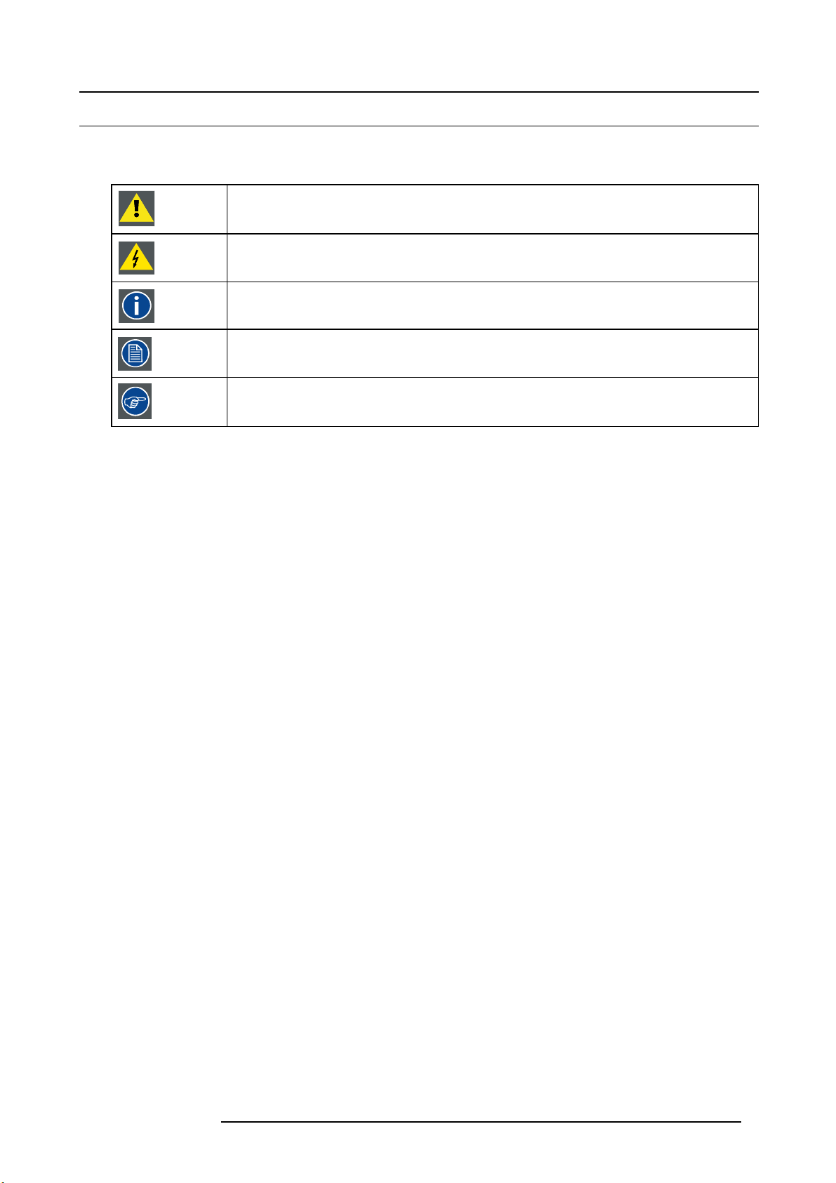
Symbol overview
The following icons are used in th e manual :
Caution
Warning
Info, term definition. General info about the term
Note: gives extra information about the described subject
Tip: gives extra advice about the described subject
Picture overview
Images and pictures given in the manual are used as illustration. The content of the images can be slightly different with the reality,
e.g. version numbers, device types, installed modules, form and position of software windows on screen ...
R5905948 E2 12/12/2014
7
Page 12

1. Introduction
1.3 The 4K screen management system E2
The E2 presentation system
Raising the bar for live screen management, the E2 presentation system provides superior image quality, exceptional input and
output density, great expandability and durability. Supporting native 4K input and output, it is the first and only screen management
system on the market that can manage a 4K p rojector blend with refresh rates up to 60Hz. A truly versatile system, it offers eight
mixable PG M outputs and four scaled Aux output for full show control with a single box.
Native 4K input and output
With native 4K input and output, the E2 provides impressive pixel processing power. Whether native or scaled inputs, two connectors
or four, this HDCP-compliant system manages it all. With 28 inputs and 14 outputs ( eight PGM, two Multi-viewer and four scaled
Aux outputs), the E2 system offers full show control, including eight independent PIP mixers and a dedicated Multiviewer. Thanks to
its linkable chassis, it can easily expand beyond these eight outputs without the need for additional external processing and routing
to distribute the signals. And as its inputs and layers can also be extended, the E2 is even c apable of managing a blend of up to 32
4K projectors.
Simple servicing and control
The E2 comes with a straightforward cross-platform user interface that provides touch
on the chas sis it enables easy control via third-party systems. Multiple users can control the system simultaneously, and the API
allows third-party developers to create custom control programs and interfaces. Thanks to its modular design, users can simply add
a new input or output card to support future signal interfaces. This modularity a
swap a specific input or output card in the case of damage, without needing to ship or replace the entire box.
Designed for life on the road
Designed for the live event industry, the rugged E2 features a steel chassis that’s able to withstand the challenging conditions of life
on the road. What’s m ore, it offers screen control in a compact form factor of only four rack units, which makes it easy to ship and
install. And thanks to its m odular cards and dual redundant power supplies, the E2 is extremely reliable and easy to service in the
field.
screen ergonomics. As the presets are stored
lso ensures great serviceability, as users can easily
8
R5905948 E2 12/12/2014
Page 13

2. SAFETY
About this chapter
Please read this chapter car efully. It contains important information to prevent pers onal injury while installing and operating E2.
Furthermore, it includes several cautions to prevent damage to the E2. Ensure that you understand and follow all safety guidelines,
safety instructions and warnings mentioned in this chapter before you begin installation. After this chapter, additional “warnings” and
“cautions” are given depending on the installation procedure. Read and follow these “warnings” and “cautions” as well.
Overview
• General considerations
• Important safety instructions
2. Safety
R5905948 E2 12/12/2014
9
Page 14

2. Safety
2.1 General considerations
General safety instructions
• Before operating this equipment please read this manual thoroughly and retain it for future reference.
• All warnings in the documentation manual should be adhered to.
• All instructions for oper ating and use of this equipment must be followed precisely.
• All loc al installation codes s hould be adhered to.
Notice on safety
This equipment is built in accordance with the requirements of the international safety standards IEC60950-1, EN60950-1,
UL60950-1 and CAN/CSA C22.2 No.60950-1, which are the safety standards of information technology equipment including
electrical business equipment. T hes e safety standards impos e im portant requirements on the use of safety critical components,
materials and insulation, in order to protect the user or operator against risk of electric shock and energy hazard and ha ving access
to live parts. Safety standards also impose limits to the internal and external temperature rises, radiation levels, mechanical stability
and strength, enclosure construction an d protection against the risk of fire. Simulated single fault condition testing ensures the
safety of the equipment to the user even when the equipment’s normal operation fails.
10
R5905948 E2 12/12/2014
Page 15

2.2 Important safety instructions
To prevent risk, personal injury and E2 damage
Please read this chapter carefully. It includes several cautions to prevent damage to the E2. Ensure that you understand and follow
all safety guidelines, safety instructions and warnings mentioned in this chapter before installing the E2. After this chapter, a dditional
“warnings” and “cautions” are given depending on the installation procedure. Read and follow these “warnings” and “cautions” as
well.
• Read and follow all installation and operation instructions.
• Only trained technicians may install the E2.
• Installation of the E2 must b e done in a dus t free area.
• Only use attachments/accessories specified by the manufacturer.
• CAUTION: Troubleshooting must be performed by a trained technician. To reduce the risk of electrical shoc
to s ervice this equipment unless you are qualified to do so.
• Refer all servicing to qualified service personnel. Servicing is required when the system has been damaged in any way, such
as liquid has been spilled or objects have fallen into the system, or the system has been exposed to rain or moisture, does not
operate normally, or has been dropped.
• FRAGILE: The E 2 is fragile. Handle the E2 with care at all times.
• To prevent injury, minimum 2 persons are required to carry the E2.
• Do not remove any c overs or pa nels during normal operation. Removal any of these items will expose sensitive electronic
circuits and the unit may be damaged.
• During maintenance operations, always switch off the E2 and unplug power cords before removing one of the covers.
• Always wear a wrist band which is connected to the ground while handling the E SD sensitive parts.
• Wear insulating gloves during the execution of the installation and maintenance actions to avoid short-circuit.
• Be careful never to drop anything into the E2 assembly during the service procedures.
• Be careful to always follow the procedures during maintenance opera tions (spare parts replacement).
• This product is intended to operate from a power source that will not apply more than 230 volts rm s between the sup ply conductors or between both supply conductor and ground. A protective ground connection by way of gro unding conductor in the
power cord is essential for safe operation.
• This product is grounded through the gro unding conductor of the power c ord. To avoid electrical shock, plug the power cord
into a properly wired receptacle before connecting to the product input or output terminals. A protective-ground connection by
way of the grounding conductor in the power cord is essential for safe operation. For 110V installations the power supply cord
should be rated at 13amps. For 220V installations the power supply cord should be rated 10amps.
• Use only the power cord and connector specified for your product. Use only a power cord
and connector changes to qualified service person nel.
• Replace spare parts only with the same parts supplied by Barco.
• Save the original shipping carton and packing material. They will c ome in handy if you ever have to ship your equipment. For
maximum protection, repack your se t as it was originally packed at the factory.
• Rated m aximum ambient operating temperature, t
• Do not operate this product in an area containing explosive materials
= 40°C (104°F).
a
.
that is in good condition. Refer cord
k, do not attempt
2. Safety
R5905948 E2 12/12/2014
11
Page 16

2. Safety
12 R5905948 E2 12/12/2014
Page 17

3. GENERAL
About this chapter
This chapter is designed to introduce you to the E2 product.
Overview
•E2overview
• Features
• Terms and definitions
• Control overview
• Presentation System overview
• Installation requirements
• Initial inspection
• E2 Rack-Mount Procedure
3. General
R5905948 E2 12/12/2014
13
Page 18

3. General
3.1 E2 overview
About E2
E2 is a is modular scalable Digital Video Processor dedicated to the live sc reen management. The E2 presentation system provides
superior image quality and an exceptional input and output density, within a single 4RU rack mount chassis. Supporting native 4K
I/O cards, it is the first and only screen management system on the market that can manage a 4K projector blend with refresh rates
up to 60Hz. A truly versatile system, it offers 28 inputs and 14 outputs (up-to eight PGM, four M ultiviewer and four scaled Aux
outputs) for full show control. Multiple E2 units can be linked in order to achieve a combination of Layer, Canvas, Input and Output
expansion*. The control interface is performed through a GUI application running Windows, Linux* or Mac platforms. E 2 covers
multiple markets including Rental & Staging, Corporate AV, Simulation, Control Rooms and Broadcast.
(*) This feature will be implem ented in a future release!
Modularity and maintainability
Thanks to its modular design, users can also simply a dd a new input or output card to support future signal interfaces. This modularity
also ensures field serviceability, as users can easily swap a specific input or output card in the cas e of damage or failures, without
needing to ship or replace the entire box.
14
R5905948 E2 12/12/2014
Page 19
3.2 Features
Inputs
8x Input card slots supporting up to 4K resolution per slot.
Each card slot will accommodate either 4x HD inputs, 2x 2,560 x 1,600 inputs, or 1x 4K input.
Card type Connector Type
HDMI/DisplayPort input card 2x HDMI 1.4 connectors
2x DisplayPort 1.1 connectors
Dual Link DVI input card 2x Dual Link DVI-D connectors
6G SDI input card 4x BN C connector supporting 6G SDI
Genlock input 2x BNC connector (Input and loop output)
Supports Black burst and trilevel analog signals
E2 ships w ith the following input cards:
•2x6GSDIcards
•2xDVIcards
• 4x HDMI/DP cards
Outputs
3x Output Card slots for PGM and Aux outputs supporting up to 4K resolution per slot.
1x Multi-viewer card slot.
Card type Connector Type
HDMI output card 4x HDMI 1.4
6G SDI output card 4x BN C connector supporting 6G SDI
HDMI Multi-viewer card 4x HDMI 1.4 connectors
3. General
E2 ships w ith the following input cards:
• 14 Outputs via 4 Output cards:
- Up to 3 x 4K Outputs - each Output card supports up to 4K@60 out
- 4 x SD/HD/3G SDI (6G ready)
- 8 x HDMI 1.4 (297 Mpix /sec max)
- 2 x HDMI 1.4 for Multiviewer (297 Mpix/sec max)
• Eight (8) Program Outputs configurable as single screens or tiled/blended widescreens
-Configurable from 8 x 2,048 x 1x200@60 max to 2 x 4,096 x 2,400@60 m ax
User interface
User interface
Event Master Software GUI based configuration and control application
Event Mas ter Console (available 2015) Dedicated hardware panel specifi cally designed to support the
API for custom User interface programming
Details
Cross platform (Mac/Windows)
E2
Allows user to create custom control programs
Processing and latency
• 12 bits/color
•36bits/pixel
• 1 frame processing latency for progressive sources
PIP layers (per chassis)
Freely assignable PiP layers seamlessly transition bet
• 2K mode: 8x seamless PiP or key overlay
• DL mode: 4x seamless PiP or key overlay
• 4K mode: 2x seamless PiP or key overlay
ween sources
R5905948 E2 12/12/2014
15
Page 20
3. General
Background mixer
Each PGM screen destination has an unscaled seamless background mixer supporting the full resolution of the de stination
• Any live input type can be a background source
• Matte color generator
• Still store as background
Destinations (single chassis)
Eight (8) Program Outputs configurable as single screens or tiled/blended widescreens.
Program screens
Layer Mode
4K Output
Dual Link output
HD (2K) Output
Auxiliary Outputs
User definable from 4 x 2,048x1,200@60 to 1 x 4K@60
Layer Mode Max. Number of Outputs
4K output
Dual Link output
HD (2K) output
Multi-viewer
Layer Mode
4K output
Dual Link output
HD (2K) output
Max. Number of Outputs
• 2x single screen s
• 1x blended (2 outputs)
• 4x single screen s
• 2x blended
• 8x single screen s
• 4x 2 output blended (2 ou tput per blend) up to 1x 8 output
blended
• 1x Scaled Aux output
• 2x Scaled Aux output
• 4x Scaled Aux output
Max. Number of Outputs
• 1x Multi-viewer output
• 2x Multi-viewer output
• 2x Multi-viewer output
Still stores
User-assigned still stores
• Live capture
• Loaded via PNG file
Presets
1,000 user de finable presets
Expandability (available 2015)
16x E2 chassis per system
Layer Mode Max. Number of Projectors
4K output
Dual Link output
HD (2K) output
16 R5905948 E2 12/12/2014
• 32 projector blend
• 64 projector blend
• 128 projector blend
Page 21

Chassis
•4RU
• Dual Redundant PSU
• Modular field swappable processing and I/O cards
• Variable flow cooling
• Rugged steel chassis
3. General
R5905948 E2 12/12/2014
17
Page 22

3. General
3.3 Terms and definitions
3G
A 3 Gbit/s serial digital 10-bit or 12-bit video interface (SMPTE 424 M and 425M).
Background (BCK)
Typically an unscaled source originating from a computer’s multi-head graphics card, or a frame grab from a scaled source. E2
provides two background s ources (BG A and BG B), each of which appears at the sy stem’s lowest priority — visually in back or
underneath all other sources.
Chroma Key
A type of key where the hole-cutting information is derived from a color rather than from a video level. A
television, is when the weatherman appears to be standing in front of a map. The map itself is a video signal, and the weatherm an
is in fact standing in front of a green (or blue) screen. On the switcher, the Chroma Key process electronically subtracts the color
from the foreground image, and replaces it with video from the background image to form a composi
Clip, Gain, Opacity
In switcher terminology, the p rocess of fine-tuning a key of any type (luminance, linear, or chroma). Clipping sets the threshold for
the hole cutting circuitry, while "gain" defines the range and sensitivity of adjustment. The "opacity" is the transparency or density of
the key, as revealed over a background.
Computer Video
A generic term indicating video that originates from a computer platform. A progressive scan signal that follows VESA (Video Electronics Standards Association) standards, with typical r esolutions of 800 x 600, 1024 x 768, 1280 x 1024, etc.
n common example on
te image.
Crosspoint
The video switch (or button) that selects the input required on a particular s witcher bus.
Cut
Cut is an instantaneous sw itch from one v ideo source to another.
DA (Distribution Amplifier)
A video device that inputs one video signal, and outputs multiple “identical” signals.
Destination (DST)
Destination is a location to which you can route t he output of an E2. A destination can be configured as:
• A single screen (one projector)
• Multiple screens (such as a wide screen application)
• An external processor (such as a Im agePRO -II)
DSK (Downstream Keyer)
A DSK is a key that is electronically located after all other switcher functions — v isually on top of all other layers and buses.
Fader
See T-Bar.
GUI (Graphical User Interface)
A term that describes a status display based on graphics a
HD-SDI (High Definition Serial Digital Interfa
HD-SDI signal is a high defi nition SDI signal (SMPTE 292M). E xam ple formats are 720p, 1080i, and 1080p.
nd icons, rather than strictly on numbers and letters.
ce)
Key
An electronic (and visual) process whereby one image is electronically superimposed over another source or background. Keys are
typically used for titles, logos, and banners .
Keyframe
In a PIP “move,” a keyframe is a point where an action or change occurs. For example, when a PIP moves from the upper right
corner to full screen, keyframe 1 is the upper right position, and keyframe 2 is the full screen position of the PIP.
18
R5905948 E2 12/12/2014
Page 23

3. General
Key Fill
The video which fills the hole cut by the keying circuitry. Typically, switchers pr ovide a variety of choices for the fill source — internal
mattes, external video, or "self" fill are several examples.
Key Mask
A key modification system that protects a portion of the foreground video from being keyed, using the switcher’s internal pattern
system.
Key Signal
Also known as Key Source. The signal that electronically cu ts the hole in the background video signal. Ke
from external inputs such as character generators or cameras.
y signals t ypically originate
Layer
An image display element (such as a PIP, Key or B ackground) that has an associated visual priority — either in front (or in back) of
another layer.
Linear Ke y
Linear key is a keying mo de in which the edges of anti-aliased key sources (such as character generators) are reproduced clearly.
Typically, two s eparate signals are required from a linear key s ource: a cut and a fill.
Menu
A term used to describe buttons and functions on the high-resolution color LCD touch screen.
Mix
Also known as a Dissolve. A transition between two video sources in which one source fades out as the other fades in.
Mixer
Circuitry that enables you to transition (and scale) P IPs and Keys over a background.
Multiviewer (MVR)
MVR is a monitoring system that enables multiple sources (input and outputs) to be displayed on one or more monitors, eliminating
the need for individual source monitors. By utilizing different arrays of PIPs, users can select the preferred multiviewer “look,” and
streamline their w o rkflow.
NTSC
National Television Standards Committee. The oldest standard for color picture broadcasting. NTSC is a standard definition format
that operates at a frequency of 60Hz, with 525 lines, 60 fi elds and 30 frames per second.
PAL
Phase Alternating Line. PAL is the NTS C equivalent TV standard in Europe. PAL is a standard definition format that operates at a
frequency of 50Hz, with 625 lines, 50 fields, and 25 frames per second.
PGM (Program)
The switcher’s main output signal.
PIP
Picture-in-Picture, an on-screen con figur ation in which one picture (typically of reduced size) is positioned over another background
image — or another PIP. PIPs can be reduced, enlarged, bordered, shadowed, and mixed on and off Program. PIPs can overlap
each other, depending on their visual priority. In E2, the multiviewer PIPs are not allowed to overlap.
Preset
Storage register in which you can store ( and recall) the entire c onfiguration or “look” of your destination(s).
PRVW (Preview)
The video that will appear ne xt on program
(main) outputs.
RGB
The red, green and blue color signal components.
RGBHV
Defines a connection scheme with five lines: one for red, one for green, one for blue, one for the hor izontal sync and one for the
vertical sync. This is the standard used in VGA and other analog PC computer monitors.
R5905948 E2 12/12/2014
19
Page 24

3. General
RGBS
Defines a connection with four signals, to transmit video and sync information. Vertical and horizontal sync are combined on a single
channel.
RGsB
Defines a connection with three signals , to transmit video and sync information. Here, the sync information is transmitted on the
green channel.
Scaler
An electronic circuit that reduces or enlarges source images, thus creating PIPs and Keys that can be pos
itioned (and transitioned).
SD-SDI (Standard Definition Serial Digital Interface)
SD-SDI is a standard d efi nition SDI signal with a data rate of 270 Mbit/s only (SMPTE 259M). Example formats are 480i and 525i.
SDI (Serial Digital Video)
A digital representation of the video signal that is distributed via a single coaxial cable with BNC connectors.
System
Refers to E2.
T-Bar
Also known as a Fader, the T-Bar is the lever on a switcher that manually controls the progress of an effect. The position of the fader
controls the amount of the BG (Background) Bus signal and the PVW (Preview) Bu
s signal that contributes to the mix, w ipe or key.
Wipe
A Wipe is a transition between two video sources that uses a selected pattern to determine the edge between the two sources.
Y/C
Y/C is a video signal in which color and brightness inform ation is transmitted separately (luminance Y, chrominance C).
20
R5905948 E2 12/12/2014
Page 25
3.4 Control overview
General
There are four ways to control the E2:
• Front Panel
• Event Master Control Software (EM GUI) running on Windows 7 PC or Mac with OS X
• Web interface running from E2
• E2 Controller *
(*) Available in 2015
Front Panel
The E2 front panel includes a power switch, a USB port and a dimmable display that works in conjugation with the ADJUST knob
and SEL and ESC buttons. Through the front panel menus you can perform basic system functions such as factory reset,
network parameters and basic diagnostics. A front-panel USB port is provided for downloading and restoring logo images and
system configurations. Refer to the chapter "Front panel", page 30 for more information about the E 2 ’s Front panel menus.
Event Master Control Software (EM GUI)
Event Master Control Software is an easy to use GUI running on a PC or MAC. The software consists of several menus and tabs
that enable you to configure your system, setup the input sources and output destinations, m anage the dedicated multiviewer and
create your presentation’s overall “look”. In addition, since the configuration parameters and presets are stored on the E2 chassis,
multiple instances of the GUI can be run simultaneously on different computers expanding the control possibilities. Refer to the
chapter "GUI orientation", page 67 for more information about the GUI. S ubseq uently in this User’s Guide, the E vent Master Control
Software will be referred as the EM GUI.
3. General
set
An API w ill be available post release 1 for developers who need to create custom control programs an d interfaces.
Web interface
Via the local network and a computer the user can access a web page server running on the E2. Basic system functions similar to
the ones available from the front panel menus are accessible through the web page server. Refer to the chapter "Settings Menu",
page 142 for more information about the E2 Web interface.
E2 Controller
The E2 controller is a dedicated hardware panel specifically designed to support the E2 . It includes preset buttons and touch screen
displays allowing for easy and direct control of the E2
The E2 controller will be available in 2015.
system.
R5905948 E2 12/12/2014 21
Page 26
3. General
3.5 Presentation System overview
Advanced video processing
The E2 Presentation System is the most advanced video processing and presentation control system on the market today. The system provides source selection, windowing, s eamles s switching, video effects and integrated control for professional presentations.
E2’s modular, scalable architecture allows the sy stem to support a wide variety of show configurations.
A word about Layers
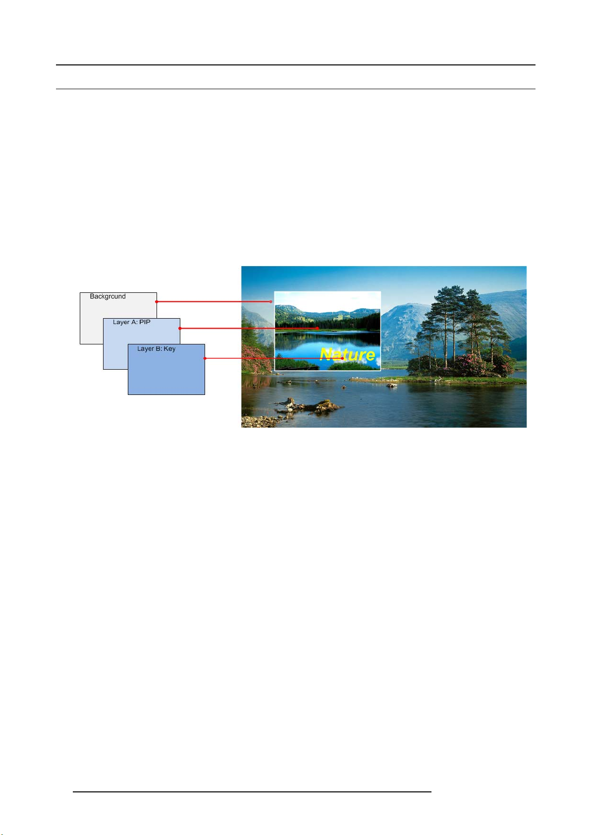
A layer is an image display element stacked on top of another or a background. Within the E2 system, each mixer has two layers,
A and B, and one Background layer. For complete flexibility, each layer can be assigned to either PIP or Key functionality.
The Background layer has the lowest priority. A ny input or inputs can be used as a background. This layer visually appears behind
all other PIPs and keys. The system can transition between two background sources.
PIP layer appears over backgrounds and under other layers of higher priority. PIP effects include mixes, smooth moves, resizing,
adjustable aspec t ratio, borders and drop shadows.
Key lay er also appears over backgrounds and under other layers of higher priority. Key effects include luminance keys, split keys
(key a lpha or fill), invert keys and chroma keys (future release).
Image 3-1
A word about Destinations
Destination is a location where the user assigns th e outputs.
We can consider three destination types:
• Single/Multiple Screen Destination (e.g. one or more projectors)
• AUX Destination (e.g. a monitor dedicated f
• An external processor Destination (e.g. ImagePRO-II).
There several rules that apply when defining an Destination configuration. For details on destination setup procedures, please refer
to the chapter "Confi guration Menu > Adjustment > Destination Confi guration", page 99.
or cam era adjustments)
22
R5905948 E2 12/12/2014
Page 27
3.6 Installation requirements
Environment conditions
Table below summarizes the physical environment in which the E2 may be safely operated or stored.
Environment Operating Non-Operating
Ambient Temperature 0°C (32°F) to 40°C (104°F) -10°C (14°F) to 60°C (140°F)
Air c leanliness Clean office environment (equivalent with cleanroom
Humidity
Altitude
standard ISO 14644-1 ISO Class 9)
5% to 85% RH Non-condensed 0% to 95% RH Non-Condensed
-60 (-197Ft) to 3000m (9843Ft) -60 (-197Ft) to 10000m (32810Ft)
CAUTION: Let the E2 acclimate t o the ambient temperature after unpacking. Ensure that the hum idity is within
the specification. Neglecting this may result in startup failure of the device.
E2 software package
This version of the E2 User ’s Guide is based on software version 01.00.00.
Verify that the E2 is loaded with the latest software version available on the Barco w eb site
(URL:h
ttps://www.barco.com/). Refer to the chapter "Updating firmware", page 183 for m or e information
about the E2 u pgrading software.
n.a.
3. General
Event Master Control Software (EMI GUI)
The EM GUI software must be at least:
• Version 01.00.00
R5905948 E2 12/12/2014
23
Page 28
3. General
3.7 Initial inspection
General
Before shipment, the E2 was inspected and found to b e free of mechanical and electrical defects. As soon as the E2 is unpacked,
inspect for any damage that may have occurred in transit. Save all packing material until the inspection is completed. If damage is
found, file claim with carrier immediately. The Barco Sales and the Service office should be notified as soon as possible.
Unpacking
At delivery the E2 is packed in a shipping c ase. Place the shipping case on a stable (solid), flat and insulated support during all
the unpacking. O pen the case from the top. Remove the E2 that is packaged in an antistatic bag. Check the box content after
unpacking.
After unpacking let the E2 acclimate to the room temperature which must be higher than 0°C (32°F) and lower
than 40°C (104°F). Neglecting this may result in startup failure of the device.
Save the original shipping case and packing material, these will be necessary if you ever have to ship your
E2. For maximum protection, repack your E 2 as it was originally packed at the factory.
Box content
After unpacking the E2 it is recommended to check if all of the following items were included:
Product Contains Accessories included
R9004698
• 4RU rack mount chassis
• 2x 14-9750004-90
• 2x B 1959864
• 2x B 1959865
• 2x B 1959860
• 2x 09-0106032-91
• 8x 13-0081012-90
• 2x 09-0106031-90
• B561132
• R5905947
• 26–1205004–00
• E2 assembly
• European Power Cord CE E7 (not included with units shipped to China)
• US Power Cord NEM A 5/15 (not included with units shipped to China)
• China Power Cord GB 2099 (only included with units shipped to China)
• CXP Expansion Link Cables
• Rear Rack Mount Support Plates
• 8-32 x .38 Pan Head Screws for Rear Rack M ount Support Plates
• Rear Rack Mount Brackets
• USB Thumb Drive (Contains Users Guide, System Software and Control GU I)
• Safety manual
• Quick Start Guide
Mechanical check
This check should confirm that there are no broken parts and the unit is free of dents or sc ratches. Your Barco Sales r epresentative
should be notified as soon as possible if this is not the case.
24
R5905948 E2 12/12/2014
Page 29

3.8 E2 Rack-Mount Procedure
General
The E2 c hassis is designed to be rack mounted and is supplied with front rackmount hardware. P lease note the following important
points:
• The E2 is 4RU in height.
• The maximum am bient operating temperature is 40 degrees C.
• Leave sufficient front and rear space to ensure that airflow through the E2 is not restricted.
• When installing equipm ent into a rack, distribute the units evenly to prevent hazardous conditions that may be created by uneven
weight distribution.
• Connect the E2 only to a properly rated supply circuit.
• Reliable grounding (earthing) of rack-mounted equipment should be maintained.
• Rack mount the E2 from the front rack ears using four rack screws (not supplied). Threads may be metric or otherwise, depending upon the r ack type.
CAUTION: At a minimum, an E2 chassis weighs 31 kg (68 lbs). To avoid injury, it is recommended that two
people rack mount the chassis.
How to install E2 in a rack
Use the following steps to rack mount the E2:
1. T he E2 is shipped with side rails included in the shipping case and not installed onto the chassis. These side rails, when they
are properly installed and adjusted, assist with the distribution of chassis (and cable) w eight within yo ur rack. Use the following
steps to properly adjust the side rails:
3. General
R5905948 E2 12/12/2014
25
Page 30
3. General
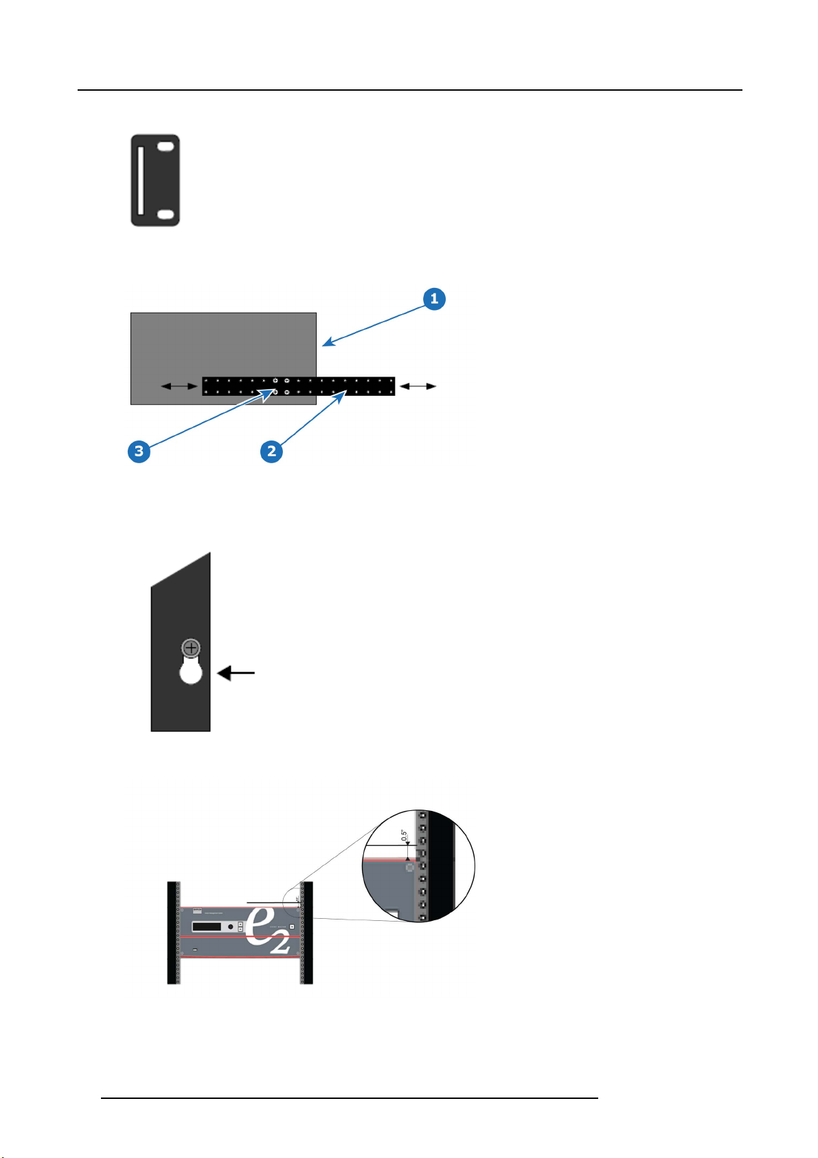
a) Measure and install the two supplied mounting brackets on your rear rack rails.
Image 3-2
b) Measure the distance between the f ront and rear rack rails. Remove the four m ounting screws that secu
Image 3-3
1 Cha ssis rear
2Siderail
3 Mounting screws
c) Re-install the mounting screws. When properly adjusted, the end of each side rail will protrude through the slot in the rear
the E2, and then adjust the spacing of each side rail as necessary.
re each side rail to
mounting bracket, once the chassis is rack mounted.
Image 3-4
To take advantage of this feature, ensure that there is at least 1/2” of clearance above the chassis.
Image 3-5
2. F or the E2’s two keyhole slots, measure and install two rac k screws in your equipment rack’s front rails. Allow each screw to
protrude approximately 3/4” from the sur face of the rails.
3. L ift the chassis, and while supporting it, slide the side rails through the slots in the rear mounting brackets.
26
R5905948 E2 12/12/2014
Page 31

3. General
4. W hile continuing to support the chassis, slide the screws (in the front rails) through the two keyholes, and let the chassis settle
up into the keyhole slots.
5. Tighten the two lower s crews, then install and tighten the two uppers screws in the rack rail.
R5905948 E2 12/12/2014
27
Page 32

3. General
28 R5905948 E2 12/12/2014
Page 33

4. HARDWARE ORIENTATION
About this chapter
This chapter explains the E2 hardware in detail.
Overview
• Front panel
• Rear panel
• 6G SDI Input Card
• Dual Link DVI Input Card
• HDMI/DisplayPort Input Card
• HDMI Output Card
• 6G SDI Output Ca rd
• Expansion link card
4. Hardware orientation
R5905948 E2 12/12/2014
29
Page 34

4. Hardware orientation
4.1 Front panel
About front panel
The figure below illustrates the E2 front panel.
Image 4-1
1
2 Barco logo
3 Display screen
4 Menu navigation buttons
5
6
Chassis Handles
Power ON/OFF button
USB port
Chassis Handles
Two Chassis Handles are provided for ease of installation and transportation.
When transporting the chassis by its handles, do not set it down with the rear connectors towards the ground.
If you do, you may damage the rear connectors.
Display screen
The 4-line x 24-character screen shows all E2 menus, sub-menus, and messages. T he display is dimmable.
At system startup, or when no menu buttons are selected, the screen displays the Status Menu. The following illustration shows
a sample Status Menu. For information about the contents of this menu, refer to the chapter titled "Front Panel Menu orientation",
page 45.
Image 4-2
Menu navigation controls
The navigation in the menus is assumed by three controls:
30
R5905948 E2 12/12/2014
Page 35

4. Hardware orientation
• Turn the ADJUST k nob to scroll through the menu items on the screen.
- Turn the knob counter-clockwise to scroll down.
- Turn the knob clockwise to scroll up.
A navigation cursor (>) to the left of a menu item indicates the position of the scroll bar, as shown in the
following illustration.
Image 4-3
• Press the SE L button to:
- Enter the Setup Menu tree from the Status Menu
- Select the menu item indicated by the navigation cursor
- Change or accept a param eter
-AnswerYes to menu queries
•PresstheESC button to exit a menu without making changes, to cancel an operation, to answer No to
menu queries, or to return to the Status M enu. Each press takes you back up the menu tree one level.
Power ON/OFF button
This button switches the unit on and off.
USB port
The USB port is provided to support uploading and downloading system configurations and upgrading E2 firmware.
R5905948 E2 12/12/2014
31
Page 36

4. Hardware orientation
4.2 Rear panel
About rear panel
The figure below illustrates the E2 rear panel.
Image 4-4
1
2
3 Two Genlock Input BNC with passive Loop-through
4 Two Expansion link cards
5
6
7
Two AC connectors
RJ-45 connector for 10/100 BaseT Ethernet communications
Eight Input cards (HDMI/DP, SDI, DVI)
Three Outputs cards (DVI, SDI)
One Multiviewer card (HDMI)
AC connectors
E2 is equipped with two redundant power supplies. During normal operation the load is shared equally by both supplies. If one
supply fails, the second carries the whole load. Two A C Connector are provided to connect the E2 to your facility’s A C power source
through the supplied power cords
Input P ower Specification: 100-240 VAC, 47-63 Hz
On each power supply there are 3 LED lights that provide status information as follows:
• DC O utput Power LED: when Green, t
• Status LED: when amber indicates that an error has occurred.
• AC Input Power LED: when green it indicates that the supply is connected to a valid AC power.
Therefore, during normal operating conditions, the input AC and Output DC LEDs will turn green.
.
he supply is outputting valid DC power.
Note that the power supplies are installed upside down, so the silkscreen markings will also appear upside
down.
Ethernet port
One RJ-45 connector is provided for 10/100BaseT E thernet c omm unications with the E2. The por t is used for runn ing the Web
Interface and for connection to an external device.
32
R5905948 E2 12/12/2014
Page 37

4. Hardware orientation
The Ethernet connec tor is compatible with:
• Standard RJ-45 E thernet cables
• Neutrik EtherCon® series cables
For pinout details, refer to the sec tion dedicated to the pinout in Appendix A, "Standard connector pinouts", page 288.
Genlock Input BNC (with passive Loop-through)
The Genlock input suppo rts NTSC and PAL Blackburst, as well as HD tri-level sync signals, per SMPTE 274M and SMPTE 296M.
The passive loop-through connector passes the Genlock signal to another device downstream of the E2. The Loop-through o utput
will continue to function even when the E2 is turned off. When the E2 is genlocked and the lock source is lost, the output of the unit
will automatically switch to “free-run” state without any discernible “glitching” on the output display device.
For G enlock connections details, refer to the Specifi cations Appendix.
Expansion link cards
A single E2 unit supports 28 inputs, 8 outputs, an integrated Multiviewer and a 16 2K layers. This feature list is generous enough
to satisfy most events. W hen, however, the event requirements exceed the specific ations of single unit, multiple E2s can be linked
together through the Expansion cards. The cards are connected with four Barco-supplied high bandwidth bi-directional expan sion
link cables. These cables are also commercially available.
The two leftmost slots are reserved for expansion c ards:
Slot Card type Connectors
1 Expansion Link Card 2x High-Speed bi-directional connectors
2 Expansion Link Card 2x High-Speed bi-directional connectors
For more details on capabilities of expansion, refer to the section "Expansion link card", page 44.
Input cards
Slots 3 through 10 are reserved for Inputs Cards. Each card supports resolu
28 inputs, eliminates, in most cases, the need to have upstream routers or scalers.
Each card slot could accommodate either:
• 4x up-to HD/2K inputs
• 2x 2560x1600 inputs
• 1x 4K input
From left to right, the distribution of cards is as follows in the 8 slots dedicated to input cards:
Slot Card type Connectors
3
4
5
6
7
8 HDMI/DisplayPort Input Card 2x HDMI connectors per 1.4a specifications
9
10 HDMI/DisplayPort Input Card 2x HDMI connectors per 1.4a specifications
6G SDI Input Card 4x BN C connectors supporting up-to 6G SDI
6G SDI Input Card 4x BN C connectors supporting up-to 6G SDI
Dual Link DVI Input Card
Dual Link DVI Input Card
HDMI/DisplayPort Input Card 2x HDMI connectors per 1.4a specifications
HDMI/DisplayPort Input Card 2x HDMI connectors per 1.4a specifications
tions up-to 4K resolutions. E2s’ ability to support up-to
2x Dual Link DVI-D connectors
2x Dual Link DVI-D connectors
2x DisplayPort connectors per 1.1a specifications
2x DisplayPort connectors per 1.1a specifications
2x DisplayPort connectors per 1.1a specifications
2x DisplayPort connectors per 1.1a specifications
The following sections describe each type of card in detail:
• "6G SDI Input Card", page 35
• "Dual Link DVI Input Card", page 37
• "HDMI/DisplayPort Input Card", page 39
Outputs cards
The next three slots are dedicated for output cards supporting up to 4K resolution per slot.
R5905948 E2 12/12/2014
33
Page 38

4. Hardware orientation
Slot Card type Connectors
11
12 HDMI Output Card 4x HDM I connectors per 1.4a specifications
13 6G SDI Output Card 4x BN C connectors supporting up-to 6G SDI
The following sections describe each type of card in detail:
• "HDMI Output Card", page 41
• "6G SDI Output Card", page 42
HDMI Output Card 4x HDM I connectors per 1.4a specifications
Multiviewer (MVR) card
Physically, the Multiviewer card is identical to the HDMI output c ard but when it’s plugged in the last slot
supporting 4 monitors. The Multiviewer card is a dedicated fully integrated monitoring solution allowing m ultiple displays to be shown
together on a single display. Up to 64 MVR windows (Sources, backgrounds, clock or destinations) c an be displayed across all 4
outputs.
The user can select from the GUI Multiviewer p age from predefined layouts, or create customize layouts, texts, backgrounds, borders
or colors of the monitors. The MVR includes several alarms such as Frozen and Loss-of-Signal indicators. For more details on
Multiviewer features, refer to the section "Multiviewer (MVR) Me nu", page 134
Slot Card type Connectors
14
HDMI Multi-viewer Card 4x HDM I connectors per 1.4a specification
it operates as a Multiviewer
34
R5905948 E2 12/12/2014
Page 39

4. Hardware orientation
4.3 6G SDI Input Card
General
This card provides 4 BNC connectors supporting S ingle Link, Dual Link and Quad Link signals, in SD, HD, 3G-SDI and 6G-SDI Ultra
HD (UHD) formats.
Currently the supported formats are up-to 3G SDI. 6G SDI format will be provided with a future software release!
The figure below illustrates the 6G SDI Input card’s rear panel connectors:
Image 4-5
6G SDI Input Card Rear Panel
1 BNC connector — SDI 1 with an LED that turns on green when a valid sync has been detected
2 BNC connector — SDI 2 with an LED that turns on green when a valid sync has been detected
3
4
BNC c onnector — S DI 3 with an LED that turns
BNC c onnector — S DI 4 with an LED that turn
on green when a valid sync has been detected
s on green when a valid sync has been detected
Features
• Default slot(s): 3, 4
• Process up to 4 signals independently
• Automatic SD, HD, 3G and 6G* Switching
• Quad Link HD-SDI Input
• Dual Link 3G-SDI Input
• Single Link 6G-SDI Input*
• Each input channel includes an LED that turns green when a valid sync is detected.
(*) Via future firmware upgrade. This feature will be implemented in a future release!
R5905948 E2 12/12/2014
35
Page 40

4. Hardware orientation
Specifications
• Supported format:
Signal type Min. BNC
connector
number
Max
channels
per card
Standard
Examples
SD
HD 1 4
3G 1 4 SMPTE 424M
4K / UHD
6G-SDI
Serial Digital Interface (SDI) is a serial link standardized by ITU-R BT.656 and the Society of Motion Picture and Television Engineers (SMPTE). SDI transmits uncomp ressed digital video over 75-ohm coaxial cable within studios, and
is seen on most professional video infrastructure equipment. The first revision of the standard, S MP TE 259M, was
defined to carry digital representation of analog video such as NTSC and PAL over a serial interface and is more popularly known as standard-definition (SD) SDI. The data rate required to transmit SD SDI is 270 Mbps. With the advent
of high-definition (HD) video standards such as 1080i and 720p, the interface was scaled to handle higher data rates
of 1.485 Gbps . The 1.485-Gbps serial interface is commonly called the HD SDI interface and is defined by SMPTE
292M, using the same 75-ohm coaxial cable. Studios and other video production facilities have invested heavily on
the hardware infrastructure for coaxial cable and have a vested interest in extending the life of their infrastructure. Fortunately, SMPTE recently ratified a new standard called SMP T E 424M that doubles the SDI data rates to 2.97 Gbps
using the same 75-ohm coaxial cable. This new standard, also called 3-Gbps (3G)-SDI, enables higher resolution of
picture quality required for 1080p and digital cinem a. 6G-SDI, a new evolution of this standard with four times the
bandwidth of standard HD-SDI will be soon available.
14
41TBD
SMPTE 259M-C 480i, 576i ( NTSC/PAL )
SMPTE 292M 1920x1080 @ 59.94i/50i
Barcolink
720x480 @ 60p/50p
1920x1080 @ 60p/50p
1920x1200 @ 60p/50p
3840x2160/23.98/24/25/29.97/30 input via 4x HD-SDI
(quadrants)
3840x2160/50/59.94/60 input via 4x 3G-SDI (quadrants)
4096x2160/23.98/24/25/29.97/30 input via 4x HD-SDI
(quadrants)
4096x2160/50/59.94/60 input via 4x 3G-SDI (quadrants)
36 R5905948 E2 12/12/2014
Page 41

4. Hardware orientation
4.4 Dual Link DVI Input Card
General
The Dual Link DVI input card includes two DV I-I dual-link connectors which can support a single or dual-link DVI video signal.
Although the D VI-I connectors includes pins that support analog signals, the DVI card doesn’t support analog
signals. If you need to connect an analog signal to the E2, you need to employ an external A/D converter.
The figure below illustrates the Dual Link DVI input card’s rear panel connectors:
Image 4-6
Dual Link DVI Input Card Rear Panel
1 DVI-I dual-link connector — DVI 1 with an LED
2 DVI-I dual-link connector — DVI 2 with an L
that turns on green when a valid sync has been detected
ED that turns on green when a valid sync has been detected
Features
• Default slot(s): 5, 6
• Process up to 2 signals independently
• 2x DVI-I dual-link connector
• Support for single or dual-link DVI v ideo signal
• Each input channel includes an LED that turns green when a valid sync is detected.
R5905948 E2 12/12/2014
37
Page 42

4. Hardware orientation
Specifications
• DVI 1.0 Specification
• Maximum H Active: 4,096, Maximum V Active: 3,072
• Supported format:
- All single link DVI formats up to 165 MHz
- All dual link DVI formats up to 330 MHz
- 4K/UHD Supported:
o
3,840x2,160/ 23.98/24/25/29.97/30 input via 1x DVIDL, 2x DVISL (L and R half) or 4x DVISL (quadrants)
o
3,840x2,160/ 50/59.94/60 input via 2x DVIDL (L and R half) or 4x DVISL (quadrants)
o
4,096x2,160/ 23.98/24/25/29.97/30 input via 2x DVISL (L and R half) or 4x DVISL (quadrants)
o
4,096x2,160/ 50/59.94/60 input via 2x DVIDL (L and R half) or 4x DVISL (quadrants)
o
4,096x2,400/ 23.98/24/25/29.97/30 input via 2x DVISL (L and R half) or 4x DVISL (quadrants)
o
4,096x2,400/ 50/59.94/60 input via 2x D VIDL (L & R half) or 4x DVISL (quadrants)
- EDID version 1.3 compatible
- HDCP version 1.4 compatible
DVI
Digital Visual Interface is a display interface developed in response to the proliferation of digital flat panel displays.
The digital video connectivity standard that was developed by DDWG (Digital Display Work Group). This connection
standard offers two different connectors: one with 24 pins that handles digital video signals only, and one with 29 pins
that handles both digital and analog video. This standard uses TMDS (Transition Minimized Different
Silicon Image and DD C (Display Data Channel) from VESA (Video Electronics Standards Association).
DVI can be single or dual link.
ial Signal) from
38 R5905948 E2 12/12/2014
Page 43

4. Hardware orientation
4.5 HDMI/DisplayPort Input Card
General
The HDMI/DisplayPort Input Card has two 19–pin HDMI connectors which can support a HDMI video signal, and two 20–pin Displayport conne ctors supporting DisplayPort video signal.
The figure below illustrates the HDMI/DisplayPort input card’s rear pane l connectors:
Image 4-7
HDMI/DisplayPort Input Card Rear Panel
1 Displayport connector — Displayport 1 with an LED that turns on green when a valid sync has been detected
2 Displayport connector — Displayport 2 with an LED that turns on green when a valid sync has been detected
3 HDMI connec tor — HDMI 1 with an LED that turns on green when a valid sync has been detected
4 HDMI connec tor — HDMI 2 with an LED that turns on green when a valid sync has been detected
Features
• Default slot(s): 7, 8, 9, 10
• Process up to 4 signals independently
• 2x 19–pin HDM I connector (Type A )
• 2x 20–pin Displayport connec tor
• Each input channel includes an LED that tur
ns green when a valid sync is detected.
HDMI specifications
• HDMI per 1.4a specifications
• Supported format:
- formats up to 2,560x1,600@60 and 3,840x1,200@60 (30 bits)
- 4K/UHD Supported:
o
3,840x2,160/ 23.98/24/25/29.97/30 input via 1x HDMI, 2x HDMI ( L and R half) or 4x HDMI (quadrants)
o
3,840x2,160/ 50/59.94/60 input via 2x HDMI (L and R half) or 4x HDMI (quadrants)
o
4,096x2,160/ 23.98/24/25/29.97/30 input via 1x HDMI, 2x HDMI ( L and R half) or 4x HDMI (quadrants)
o
4,096x2,160/ 50/59.94/60 input via 2x HDMI (L and R half) or 4x HDMI (quadrants)
- EDID version 1.3 compatible
- HDCP version 1.4 compatible
R5905948 E2 12/12/2014
39
Page 44

4. Hardware orientation
DisplayPort specifications
• DisplayPort per 1.1a specifications
• Supported format:
- formats up to 2,560x1,600@60 and 3,840x1,200@60 (30 bits)
- 4K/UHD Supported:
o
3,840x2,160/ 23.98/24/25/29.97/30 via 1x DP, 2x DP (L and R half) or 4x DP (quadrants)
o
3,840x2,160/ 50/59.94/60 via 2 x DP (L and R half) or 4x DP (quad rants)
o
4,096x2,160/ 23.98/24/25/29.97/30 via 1x DP, 2x DP (L and R half) or 4x DP (quadrants)
o
4,096x2,160/ 50/59.94/60 via 2 x DP (L and R half) or 4x DP (quad rants)
o
4,096x2,400/ 23.98/24/25/29.97/30/50/59.94/60 via 2x DP (L and R half) or 4x DP (quadrants)
- EDID version 1.3 compatible
- HDCP version 1.4 compatible
HDMI
HDMI (High-Definition Multimedia Interface) is a compac t audio/video interface for transferring uncompressed video
data and compressed/uncompressed digital audio data from a HDMI-compliant device ("the source device") to a compatible com puter monitor, video projector, digital television, or digital audio device. HDMI is a digital replacement for
existing analog video standards.
DisplayPort
Digital display interface developed by the Video E lectronics S ta ndards Association (VESA). This royalty-free interface
is primarily used to c onnect a video source to a display device such as a computer monitor, though it can also be used
to transmit audio, USB, and other forms of data. VESA designed it to replace VGA, DVI, and FPD-Link. Backward
compatibility to VGA and DVI by using active adapter dong les enables users to use DisplayPort fitted video sources
without r eplacing existing display devices.
40 R5905948 E2 12/12/2014
Page 45

4.6 HDMI Output Card
General
The HDMI Output Card has four 19–pin HDMI connectors which c an provide a HDMI video signal.
The figure below illustrates the HDMI output card’s rear panel connectors:
4. Hardware orientation
Image 4-8
HDMI Output Card Rear Panel
1 HDMI connector — HDM I 1
2 HDMI connector — HDM I 2
3 HDMI connector — HDM I 3
4 HDMI connector — HDM I 4
Features
• Default slot(s): 11, 12, 14
• Provide up to 4 independent signals
• 4x 19–pin HDM I connector (Type A )
• The two connectors support single link signals up-to 300MHz .
Specifications
• HDMI per 1.4a Spec ifica tio n
• Supported format:
- formats up to 2,560x1,600@60 and 3,840x1,200@60 (30 bits)
- 4K/UHD Supported:
o
3,840x2,160/ 23.98/24/25/29.97/30 input via 1x HDMI, 2x HDMI ( L and R half) or 4x HDMI (quadrants)
o
3,840x2,160/ 50/59.94/60 input via 2x HDMI (L and R half) or 4x HDMI (quadrants)
o
4,096x2,160/ 23.98/24/25/29.97/30 input via 1x HDMI, 2x HDMI ( L and R half) or 4x HDMI (quadrants)
o
4,096x2,160/ 50/59.94/60 input via 2x HD
- EDID version 1.3 compatible
- HDCP version 1.4 compatible
MI (L and R half) or 4x HDMI (quadrants)
R5905948 E2 12/12/2014
41
Page 46

4. Hardware orientation
4.7 6G SDI Output Card
General
The 6G SDI Output Card has 4 BNC connectors which can support Single Link, Dual Link and Quad Link signals, in SD, HD, 3G-SDI
and 6G-SDI Ultra HD (UHD) formats.
The figure below illustrates the 6G SDI Output Card’s rear panel connectors:
Image 4-9
6G SDI output Card Rear Panel
1
2
3
4
BNC connector — SDI 1
BNC connector — SDI 2
BNC connector — SDI 3
BNC connector — SDI 4
Features
• Default slot(s): 13
• Provides up to 4 signals independently
• Automatic SD, HD, 3G and 6G* Switching
• Quad Link HD-SDI Input
• Dual Link 3G-SDI Input
• Single Link 6G-SDI Input*
(*) Via future firmware upgrade. This feature will be implemented in a future release!
42
R5905948 E2 12/12/2014
Page 47

Specifications
• Supported format:
Signal type Min. BNC
connector
number
Max
channels
per card
Standard
4. Hardware orientation
Examples
SD
HD 1 4
3G 1 4 SMPTE 424M
4K / UHD
14
41TBD
SMPTE 259M-C 480i, 576i ( NTSC/PAL )
SMPTE 292M 1920x1080 @ 59.94i/50i
Barcolink
720x480 @ 60p/50p
1920x1080 @ 60p/50p
1920x1200 @ 60p/50p
3840x2160/23.98/24/25/29.97/30 input via 4x HD-SDI
(quadrants)
3840x2160/50/59.94/60 input via 4x 3G-SDI (quadrants)
4096x2160/23.98/24/25/29.97/30 input via 4x HD-SDI
(quadrants)
4096x2160/50/59.94/60 input via 4x 3G-SDI (quadrants)
R5905948 E2 12/12/2014 43
Page 48

4. Hardware orientation
4.8 Expansion link card
About Expansion link
When is necessary to expand beyond the capabilities of a single E2 unit m ultiple E2s can be connected together vial the link card.
CXP
CXP is a copper c onnector system specified by the InfiniBand Trade Association. It provides twelve 10 Gbit/s links
suitable for single 100 Gigabit Ethernet, three 40 G igabit Ethernet channels, or twelve 10 Gigabit E thernet channels
or a single Infi niband 12× QDR link. The connector has 4 rows, each of 21 pin, total 84 pins.
[Note 1]: The C is the Roman numeral for 100.
General
The Link card has 2 CXP connectors w hich can support up to 12 10-Gbit channels.
The figure below illustrates the Link card’s rear panel connectors:
Image 4-10
1 CXP connector — CX P 1
2 CXP connector — CX P 2
Features
• Default slot(s): 1, 2
• Provide up to 12 10-Gbit channels
Specifications
• CXP Specification
44
R5905948 E2 12/12/2014
Page 49

5. Front Panel Menu orientation
5. FRONT PANEL MENU ORIENTATION
About this chapter
This chapter describes E2 front panel menus, including how they are accessed and the functions or parameters that are available.
The menu trees are presented in block diagram format throughout the chapter.
Overview
• Power-up initialization
• E2 Front Panel m enu tree
• Using menu system
• About Status menu
• About Setup menu
• About the System menu
• System menu > Black Invalid
• System menu > USB device (Backup/Restore)
• System menu > Ethernet
• System menu > VFD brightness (display brightness)
• System menu > Diagnostics
• System menu > Lock front panel
• Using the Tech Su pport menu
• Restoring Factory Default Settings
• Firmware Upgrade
•SaveAll
R5905948 E2 12/12/2014
45
Page 50

5. Front Panel Menu orientation
5.1 Power-up initialization
Initialization
Ensure that yo ur system is prop erly installed and cabled. M ake sure the two AC Connector are properly connected to your facility’s
AC power source through the two supplied power cords. Locate the power button on the front panel and turn power On. While the
system is initializing, the front-panel buttons light up one at a time, and the following messa ge is displayed.
Image 5-1
System Initializ a tion Message
After s ystem initialization is complete, t he Status menu appears.
46 R5905948 E2 12/12/2014
Page 51

5. Front Panel Menu orientation
5.2 E2 Front Panel menu tree
About this section
The diagram below illustrates the E2 Front Panel menu tree. Please use this diagram for reference as you learn how to operate the
system.
Menu tree
Image 5-2
R5905948 E2 12/12/2014 47
Page 52

5. Front Panel Menu orientation
5.3 Using menu system
General
This section describes the conventions for using the E2’s menu system. For reference, the following illustration shows the Syste m
Menu.
Image 5-3
System menu
The E2’s display screen is four lines high. Throughout this chapter, entire menus are shown for ease of reference, unless otherwise n oted.
Please note the following important menu rules and conventions:
• The top line names the current menu, in upper-case letters.
• Subsequent lines typically display two fields:
-Forafunction, the left-hand field names the function. The right-hand field shows the function’s current parameter (or value).
In the preceding illustration, Black Invalid is a function and On is its current value.
-Forasubmenu, the left-hand field names the submenu that you can access. The right-hand fi eld displays a double arrow
(>>), indicating that a submenu is available. In the prec eding illustration, USB Backup/Restore and Ethernet are two of
the available submenus. To use a submenu, scroll to it and press SEL. Then scroll through the list that appears.
-Thenavigation cursor (>) in the left-hand column indicates the current line on which you can take action. This arrow moves
as you rotate the ADJUST knob on the front panel. When you reach an editable field and press SEL, the navigation cursor
changes to an edit cursor (#).
Making a menu selection
To select a menu item, use the ADJUST knob to scroll to the item, then press the SEL button on the front panel:
• To scroll through a menu:
- Turn the ADJUST knob counter-clockwise to scroll down.
- Turn the ADJUS T knob clockwise to scroll up.
• To open a submenu, s croll to the subme nu line and press SE L .
• To change a parameter, scroll to the desired line and press SEL. The navigation cur sor changes to the edit cursor. Use t he
ADJUST knob to m odify the value:
- Turn the ADJUST knob clockwise to increase a value.
- Turn the ADJUST knob counter-clockwise to decrease a value.
• Then press SEL to accept a parameter or value. The edit cursor changes bac k to the navigation cursor.
You must press SEL to accept the value.
Throughout this user’s guide, the term “select” is used as an abbreviation for “scroll to a menu line and press
SEL.”
Example: Select the Ethernet men u to begin configur
ing network settings.
Exiting a menu
• In the edit mode (i.e., the edit cursor is visible), press ESC to exit a menu without changing the original par ameter.
• To navigate back up the menu structure, press ESC again. Each press takes you back up the menu tree by one level.
48
R5905948 E2 12/12/2014
Page 53

5. Front Panel Menu orientation
Answering a menu query
The SEL button is used to answer Yes to certain menu queries. The ESC button is used to answer No to menu queries. Sometimes
the two buttons are appropriate for answer to a menu queries. The following illustration shows an example of a menu query.
Image 5-4
Validation error message
Edit name
Sometimes, it is necessary to edit name, like the name of a configuration file, for example. To modify name use the following
procedure:
1. Navigate to submenu (For example, the following illustration shows the USB Backup Config submenu).
Image 5-5
USB Backup Config submenu
The navigator cursor (>) is at the field targeted.
2. Press SEL
The navigation cursor changes to the edit cursor. A blank field for the first character becomes available and this field is marked
by an underscore.
3. Use the ADJUST knob to scroll to the fi rst character you want to use for the format name.
Turning the ADJUST knob clockwise once moves to the next letter of the alphabet. I f you s tart with an upper-case letter,
as shown in the preceding illustration, then th e next letter is also a capital letter. If you start with a lower-case letter, the
next letter is a lower-case letter:
-F–>G
-f–>g
If y ou start with a number, the next character is a number.
Continuing to turn the ADJUST knob clockwise at the end of the upper-case alphabet displays a series of punctuation marks
you can use in the format name.
Continuing to turn the knob clockwise at the end of the punctuation marks displays the lower-case alphabet in order.
When you reach the end o f the lower-case alphabet, turn the
ADJUST knob counter-clockwise to scroll back through
the options in order.
4. Press SE L . The cursor moves to the next character field, which is now blank with an underscore.
5. Repeat the previous steps as many times as needed, pressing SEL for each character selection.
6. When you have selected all the characters, press SEL again to save the name.
A file name can consist of up to 19 alpha-nu meric characters.
R5905948 E2 12/12/2014 49
Page 54

5. Front Panel Menu orientation
5.4 About Status menu
General
The Status Menu is the E2 ’s top-level menu, which appears by default at system startup. This menu provides system name, Unit ID,
Genlock status and E2 IP address. The following figure illustrates a sample Status Menu. Press the ESC button w h en the Setup
menu is displayed allows to return in the Status menu.
Image 5-6
Status menu
System name
Human readable nam e of the current E2 system. Particularly useful in the user interface when multiple E2 system are connected in
the same network.
System1 is the default value. This name can be changed in the configuration page of the GUI. For more details please refer to the
section dedicated to the E2 configuration in the chapter "Configuration Menu", page 76.
Unit ID
ID required to identify different units are acting as a single system in order to expand for Inputs, Outputs or Layers.
This ID can be changed in the configuration page of the GUI. For more de
configuration in the chapter "Configuration Menu", page 76.
tails please refer to the section dedicated to the E2
Genlock
This line gives information about the Genlock connection situated at the back of the E2 system. For more detail on this connection
please refer to the section dedicated to the Genlock Input BNC in the chapter"Rear panel", page 32.
The user could turn Genlock OFF or ON in the configuration page of the GUI. E2 will determine what kind of Genlock is connected
and will update the Status field. The status field can say “Locked”, “Lost Lock” or “Free Run”. For more details please refer to the
section dedicated to the E2 configuration in the chapter "System Setup", page 157.
IP address
IP address of the E2 system in the local network.
If there is no internet connection, or if a DHCP ser
needed for running the Web Interface and for connection to an external device. For m ore details please refer to the section dedicated
to the setting of Ethernet options in the chapter "About the Sys tem menu", page 52
ver has not been found, the IP address is 000.000.000.000. The IP address is
50
R5905948 E2 12/12/2014
Page 55

5. Front Panel Menu orientation
5.5 About Setup menu
General
The Setup menu, shown in the following illustration, is the menu from which you access all operational menus. To display the Setup
menu, press the SEL button on the front panel when the Status menu is displayed, or press the ESC button to go back from a
submenu (one level for each time you press the button).
Image 5-7
Setup menu
From the Setup menu, you can configure certain system settings for the E 2, display Technical Support contact information, restore
factory default settings, and check for available fi rmware updates. And finally, you can save all the recent changes to the system.
The following sections des cribe each Setup Menu option in detail, except for the Code Upgrade feature. For details about that
option, r efer to the chapter "Updating firmware", page 183:
• "About the S ystem menu", page 52
• "Using the Tech Support menu", page 63
• "Restoring F actory Default Settings", page 64
• "Updating firmware", page 183
• "Save All", page 66
R5905948 E2 12/12/2014
51
Page 56

5. Front Panel Menu orientation
5.6 About the System menu
General
The System M enu, shown in the following illustration, allows you to view and change settings such as HDCP status and Ethernet
options. In this menu you can also backup or restore E2 configuration, obtain diagnos tic information, adjust the intensity or lock the
display screen.
Image 5-8
System menu
The following sections describe each Setup Menu option in detail:
• "System menu > B lack Invalid", page 53
• "System menu > USB device (Backup/Restore)", page 54
• "System menu > Ethernet", page 56
• "System menu > VFD brightness (display brightness)", page 58
• "System menu > Diagnostics", page 59
• "System menu > Lock front panel", page 62
52
R5905948 E2 12/12/2014
Page 57

5. Front Panel Menu orientation
5.7 System men u > Black Invalid
General
The Black Invalid s ystem setting determines whether the output is black when connected to a signal it cannot process. Black
Invalid is either On or Off. The default setting is On. This is a global setting, applicable to all outputs.
R5905948 E2 12/12/2014
53
Page 58

5. Front Panel Menu orientation
5.8 System menu > USB device (Backup/Restore)
General
The front panel of the E2 contains a USB port that you can use to connect a flash drive to the E2.
The flash drive must be formatted to use the FAT32 file system. For formatting instructions, refer to section
Formatting the flash drive in the chapter "Upgrading firmware using the USB port", page 184.
The following illustration shows the U SB Backup/Restore submenu, which you access from the System menu.
Image 5-9
USB submenu
Using this m enu, you can:
• Detect the presence of a USB device.
• Backup and restore E2 configuration files. When you connect a flash drive to the E2, the E2 creates a directory titled E2Backup
on the drive. All configuration filesaresavedtothisdirectory.
Howtobackupaconfiguration file to a flash drive?
1. Insert a formatted flash drive in the E2’s front-panel USB port.
2. F rom the System menu, scroll to the USB Backup/Restore submenu. Select Backup Config.
The USB Backup Config submenu appears, as shown in the following illustration. The navigation c ursor appears at the default
name for the first backup file.
Image 5-10
USB Backup Config submenu
3. If you wish to change the default name of the backup con
described in section "Using menu s ystem", page 48. Press SEL again when you complete the name change.
4. S croll to Backup Config and press SEL.
Aconfirmation message appears when the backup is complete.
If the backup operation fails, the message shown in the following illustration appe ars. Check that the flash drive is properly
formatted and installed, and try again.
figuration, press SEL.UsetheADJUST knob to change the name, as
Image 5-11
How to restore a system configuration fil
1. Insert a formatted flash drive in the E2’s front-panel USB port.
2. F rom the System menu, scroll to the USB Backup/Restore submenu. Select Restore Config.
54
ethatisstoredonaflash drive?
R5905948 E2 12/12/2014
Page 59

5. Front Panel Menu orientation
The USB Restore Config submenu appears, as shown in the following illustration.
Image 5-12
3. P ress SEL and scroll through the list of configuration files. When you locate the file you want, press SEL again.
4. S croll to Restore Config and press SEL.
A message confirm s the restore operation and instructs you to reboot the E2.
You m ust reboot the E2 to use the restored configura tion file.
R5905948 E2 12/12/2014 55
Page 60

5. Front Panel Menu orientation
5.9 System menu > Ethernet
General
The Ethernet su bmenu allows the user to view and change certain Ethernet settings.
Image 5-13
Using this m enu, you can:
• Query the DHCP server for a valid IP address, or turn off this feature.
• Set a static IP address for the E2, along with a subnet mask and gateway. This feature is available only if DHCP is turned Off.
• View the E 2’s IP address.
If there is no internet connection, or if a DHCP server has not been found, the IP address is 000.000.000.000. In this case, the
E2 ignores the Ethernet port.
• View the Media Access C ontrol (MAC) address of the E2’s Ethernet port.
Query t he DHCP server
In the Ethernet submenu, the d efault setting for DHCP is On. When DHCP is turned on, the E2 automatically queries the DHCP
server for a valid IP address. If the E2 receives an IP address, that address is displayed in the Ethernet submenu.
It can take several seconds to obtain an address from the server. During this time, the SEL b utton remains lit.
When DHCP is off, you can manually enter a static IP address, along with a subnet mask and gateway, in the Set Static IP submenu.
Consult your network administrator for a valid IP address, subnet mask and gateway.
Setting a static IP Address
When a DHCP s erver is not available, you can set the E 2’s IP address, using the Set IP submenu shown in the f ollowing illustration.
Image 5-14
Set IP Submenu (sample)
How to set a static IP address?
1. E nsure that the DHCP setting is Off.
2. F rom your network administrator, obtain a v alid IP address, including subnet and gateway.
3. O n the Ethernet submenu, select Set Static IP.
4. O n the Set IP submenu, select SUB(net). The last character in the fi rst field becomes available, as indicated by the empty field
and an underscore.
Note: You must change the SUB parameter before editing either of the other parameters.
5. Turn the ADJUST knob to change the first value. As you continue turning the knob, you can change all three values in this field.
Values range from 000 to 255 in all four fields.
6. P ress SEL to accept your change in the fi rst field. The last character in the next field becom es available.
7. Continue until you have created the subnet value you want. Press SEL.
8. M a ke similar changes in the GW and IP fields.
9. P ress SEL to accept your final change.
56
R5905948 E2 12/12/2014
Page 61

5. Front Panel Menu orientation
If you press ESC at any time before accep ting your final change, all your edits will be removed, and the original
values restored.
R5905948 E2 12/12/2014 57
Page 62

5. Front Panel Menu orientation
5.10 System menu > VFD brightness (display brightness)
General
The VFD Brightness submenu adjust the intensity of the front panel vacuum fluorescent display (VFD) screen. The adjustment
range is +0 to +6,with+6 being the brightest. The default setting is +3.
58
R5905948 E2 12/12/2014
Page 63

5. Front Panel Menu orientation
5.11 System menu > Diagnostics
General
The following illustration shows the Diagnostics submenu, which you access from the S ystem menu.
Image 5-15
The Diagnostics options allow a user to check if the E2 is functioning normally. Front panel and card operations can be checked.
Various system temperatures can be monitored and backup log files can be saved for customer service troubleshooting.
Front Panel
When Front Panel is selected to be tested, the VFD display will initially be blanked. Then the 24 x 4 c haracter g rid will start to show
from the dimmest setting to the brightest s etting. At this point a user can determine if any of the pixels or if a character segment is
bad in the display.
After several seconds of showing all pixels on at the brightest setting, the E 2 will automatically advance to the ENCODER/BUTTON
TEST menu (the next menu).
Directly select “Encoder/Button” from the Diagnostic menu will allow the user to test the keys and knob without the need to see the VFD being tested.
Encoder/Button
Image 5-16
The ENCODER/BUTTON TEST menu allow the user to test the k eys and knob.
When the knob on the front panel is rotated, a num ber will be displayed on the encoder line. The larger the number, the faster the
knob was rotated. The number will show as p
Pressing any key on the front panel will show the B utton Code for the key.
Button
ESC
PWR 7
SEL 14
Code
0
ositive or negative depending on the direction the knob was turned.
Hold ESC to exit and return to the DIAGNOSTIC menu.
R5905948 E2 12/12/2014
59
Page 64

5. Front Panel Menu orientation
Cards
Image 5-17
The Card Slot test will perform a variety of diagnostics for an individual card or for all cards. This is a quick way to determine if a given
card is having a problem. After selecting a Slot number or choosing All cards to be tested, the f
Image 5-18
Pressing SE L to continue will start the diagnostic testing. The following message will be displayed.
ollowing message will be displayed.
Image 5-19
If only one slot was selected for testing, a simply PAS S/FAIL result will be shown for that slot.
Image 5-20
If all slots were selected for testing, the PASS/FAIL result will be shown for all slots.
Image 5-21
If a slot is not populated with a card, the result will show EMPT Y.
60 R5905948 E2 12/12/2014
Page 65

5. Front Panel Menu orientation
To see more detailed results of diagnostic testing, run diagnostics from the Event Master Control Software.
For details on this fonction, please refer to chapter "Settings Menu > WebKit area > Dashboard", page 145
Temperature
Image 5-22
The DIAGNOSTIC TEMPERATURE menu will show real time measurem ents for the System, Motherboard and all card slots. All
temperatures are shown in degrees Celsius.
Backup Log Files
Backup log files can be saved for customer service troubleshooting.
In the event the E2 log files need to be backed u p, first install a USB stick in the front panel of E2.
When Backup Log Files is selected, the E2 will immediately write its log files to the USB stick. T he following menus will be sh own
during this process and the E2 will automatically return to the DIAGNOST IC menu once this process is complete.
Image 5-23
Image 5-24
The file name will be “E2LogFiles.tar.gz”, and it can be found on the USB stick under the “E2\backup” directory.
R5905948 E2 12/12/2014 61
Page 66

5. Front Panel Menu orientation
5.12 System menu > Lock front panel
General
When the E2’s front panel is locked, button presses have no effect. In the locked mode:
• All button presses (including Power ON/OFF button) and all turns of the ADJUST knob are ignored.
• All Ethernet communications commands function normally.
How to enable and disable the front-panel lock?
1. O n the System menu, scroll to Lock Front Panel and press SEL. The front panel is locked, and the following message appears:
Image 5-25
Front Panel Locked Message
2. To disable the front panel lock, press and hold the SEL and ESC buttons sim ultaneously for 3 seconds. When the panel is
unlocked, the dis play screen displays the St atu s menu.
62
R5905948 E2 12/12/2014
Page 67

5. Front Panel Menu orientation
5.13 Using the Tech Support menu
General
The Tech Support Menu, shown in the following illustration, provides quick access to Customer Support contact information, and
also shows you the software version for your E2.
Image 5-26
Tech Support Menu
This menu displays:
• The software version of your E2. For more details on software upgrade instructions please refer to section "Updating firmware",
page 183.
• The US Customer Support telephone number. This number is accessible from 6 a.m. to 10 p.m. (PST), 7 days per week. The
European customer support number is: 0800-90-0410. In China call: 40088-22726. All other regions, call your local Barco
support.
• The Customer Sup port web site address for all regions.
R5905948 E2 12/12/2014
63
Page 68

5. Front Panel Menu orientation
5.14 Restoring Factory Default Settings
General
As shown in the following illustration, two options in the Setup Menu allow you to restore the E2 to its factory default condition.
Image 5-27
The following attributes constitute a factory default condition:
•TheStatus Menu is shown in the display screen.
• All custom configurations are deleted.
The Factory Reset Menu provides two options for restoring factory default settings:
• Factory Reset — If you use this option, all of your system configuration are deleted. Settings will be restored to the original
factory defaults.
• Factory Reset , Save IP — This option performs a factory reset, but retains the IP address of the E2.
It is advisable to clear all saved configurations when you use the E2 for the first time, or when returning an
E2 from an event.
Restoring all factory settings
To restore all default settings to the E2, use the following procedure:
1. S elect Factory Reset from the Setup Menu.
The Factory R eset Menu appears.
2. S elect Factory Reset.
A prompt appears, asking if you want to clear all configurations.
3. P ress SE L.
The system turns off, then reboots.
If you press ESC to c ancel the operation instead, your custom setti
Reset Menu.
ngs remain in place and you are returned to the Factory
Retaining the IP address when restoring factory settings
To restore default settings to the E 2 but retain the unit’s IP a ddress, use t he following procedure:
1. S elect Factory Reset from the Setup Menu.
The Factory R eset Menu appears.
2. S elect Factory Reset, Save IP.
A prompt appears, asking if you want to clear all configurations.
3. P ress SEL to reset the system but save the I P add ress.
The system turns off, then reboots.
If you press ESC to c ancel the operation instead, your custom settings remain in place and you are returned to the Factory
Reset Menu.
64
R5905948 E2 12/12/2014
Page 69

5. Front Panel Menu orientation
5.15 Firmware Upgrade
General
The E2 provides two options for upgrading firmware :
• Using the U SB port on the front panel.
• Using the Web Interface.
Please refer to the chapter "Settings Menu", page 142 for the instructions on how to p erform firmware upgrades through the USB
memory or the web interface.
R5905948 E2 12/12/2014
65
Page 70

5. Front Panel Menu orientation
5.16 Save All
General
Save All on the Setup menu saves your custom confi guration parameters in non-volatile memory.
If you save the system state, these parameters are restored the next time you power up the E2. If you do not us e this function, your
custom settings are not restored during the next system power up sequence.
Saving all modified settings
1. S elect Save All from the Setup menu.
The following message appears:
Image 5-28
“Saving all” message
2. Wait few seconds ...
Parameters are saved in non-v olatile memory and you are returned to the Setu p menu.
66
R5905948 E2 12/12/2014
Page 71

6. GUI orientation
6. GUI ORIENTATION
About this chapter
This c hapter provides a detailed description of each section of EM GUI.
About EM GUI
The Event Master (EM ) GUI is a U I program that enables users to interface with the E2 from a P C or M ac via an Ethernet connection. The program provides a step-by-step approach to configure, program, setup the dedicated Multiviewer and manage system
functions.
Some screenshots and descriptions provided in this chapter may not accurately reflect the released software.
Barco will update the documentation in a timely mann er to m irror the released software
R5905948 E2 12/12/2014 67
Page 72

6. GUI orientation
Overview
• General requirements
• Download of Ev ent Master Control Software
• Software installation
•Startingup
• Screen layout presentation
• Controls
•Configuration Menu
•Configuration Menu > Device area
•Configuration Menu > System d iagram area
•Configuration Menu > System m odifier area
•Configuration Menu > Adjustment ar ea
•Configuration Menu > Adjustment > Unit Configuration
•Configuration Menu > Adjustment > Input Configuration
•Configuration Menu > Adjustment > Background Configuration
•Configuration Menu > Adjustment > Output Configuration
•Configuration Menu > Adjustment > Destination C onfi guration
• Programming Menu
• Programming Menu > Sources a rea
• Programming Menu > Diagram area
• Programming Menu > L ayer Modifier area
• Programming Menu > Adjustment area
• Programming Menu > Adjustment area > Layer configuration
• Programming Menu > Adjustment area > Background configuration
• Programming Menu > Adjustment area > User keys configuration
• Programming Menu > Adjustment area > Presets configuration
• Programming Menu > Adjustment area > Source adjustment
• Programming Menu > Adjustment area > Global Transition Rate/Trans/Cut
• Multiviewer ( MV R) Menu
• Multiviewer M enu > Resource area
• Multiviewer Menu > Multiviewer Layout area
• Multiviewer M enu > Modifier area
• Multiviewer Menu > A djustment area
• Multiviewer Menu > Adjustment area > O utput Color
• Multiviewer M enu > Adjustment area > Window adjustment
• Settings Menu
• Settings Menu > WebKit area
• Settings M enu > WebKit area > Dashbo ard
• Settings Menu > WebKit area > Tools
• Settings Menu > WebKit area > Tools > Manage Software
• Settings Menu > WebKit area > Tools > Backup & Restore
• Settings Menu > WebKit area > Help
• Settings M enu > WebKit area > Contact us
• Settings M enu > WebKit area > Follow us
68
R5905948 E2 12/12/2014
Page 73

6.1 General requirements
System requirements for Microsoft Windows
Minimum hardware specifications :
• PC Pentium IV or equivalent, 1 GHz or faster
•8GBRAM
• Free hard disk spac e: 600 MB
• SXGA resolution (1280 x 1024)
• Ethernet connection
Software
• Windows XP Professional, Windows 7, Windows 8
System requirements for Linux
Linux version is not available now ! This feature will be implemented in a future release!
6. GUI orientation
R5905948 E2 12/12/2014 69
Page 74

6. GUI orientation
6.2 Download of Event Master Control Software
Overview
The Event Master Control Software can be downloaded for free from Barco’s website, (URL: http://www.barco.com). The so ftware
is also available on myBarco and login to get access to secured information. Registration is necessary.
If you are not yet registered, click on New to myBarco and follow the instructions.
It is not necessary to install any other software.
70
R5905948 E2 12/12/2014
Page 75

6. GUI orientation
6.3 Software installation
Currently the EM GUI is available for P Cs with Microsoft Win 7 and Apple MACs with OS X. The software will
run on other Microsoft and M ac operating systems, but currently Barco only supports software installations
with Win7 and OS X co mp uters. Linux version o f the software will be available in a future release.
To install on Microsoft Windows
The process of installing your software involves the follow ing steps
1. B rowse to the directory where the install program is downloaded.
2. Run the install program and follow the instructions.
Software updates
For a new version of the software, download the zip file and follow the instructions as in the first installation. The new version will
be installed on the sam e location and the previous version w ill be overwritten.
R5905948 E2 12/12/2014 71
Page 76

6. GUI orientation
6.4 Starting up
How to start up
1. Double click on the Event Master Control Software icon on your desktop
Or,
click Start → All programs → Barco → E2 →Event Master Control Software
The software starts up with the same look and feel as when it was closed before.
The con nection is autom atically restored with the E 2 system if it is still available.
72 R5905948 E2 12/12/2014
Page 77

6. GUI orientation
6.5 Screen layout presentation
General
The user interface is organized around a Menu Navigation bar at the left of the screen and a Working area in the rest of the screen.
The layout of the screens is similar throughout the GUI.
In order to explain the layout, we will examine the start-up screen of the Configuration Menu and describe it’s the different components. The screens for the other menus follow the same structure and flow.
Image 6-1
1 Menu navigation bar
2 Title bar
3
4 Diagram area
5
6
Selection area
Modifier area
Configuration area
Menu navigation bar
On the far left hand side of the screen is the Menu Navigation bar that allows users to navigate between the different screens and
save or restore system configurations. This area of the screen is always visible and remains unchanged. The available buttons on
the Menu Navigation bar are:
• System Configuration: allows access to System Configuration Menu.
• Programming: allows access to Programming Menu.
• Multiviewer:allowaccesstoMultiviewer Menu.
• E2 built-in web page.
• System Save and Restore.
Title bar
On the top of the w orking area a title bar indicates the name of the selected page (e.g. System configuration).
Selection area
The selection area allows the users to select the System, Device or inputs that will be used.
Diagram area
In the middle, is the Diagram area where the system, Screens and Multiviewer are represented graphically.
R5905948 E2 12/12/2014
73
Page 78

6. GUI orientation
Configuration area
On the right ha nd side, is the configuration area where users perform all needed adjustments.
74
R5905948 E2 12/12/2014
Page 79

6.6 Controls
General
Edit box
Edit box is used to edit the v alues or names.
Image 6-2
Properties:
• By double clicking, the background changes to a dark blue color indicating that modifications can be made.
• The cursor is placed on the last c haracter.
• The er aser button allows deletion of all the characters in the edit box.
Slider box
The slider allows modification of the value with slider.
Image 6-3
Properties:
• Slide the c ursor to modify the value.
• The value can also modified by clicking the + or – symbols.
6. GUI orientation
Drop-down menu
Drop-down m enu allows the user to choose one value from a list.
Inactive drop-down:
Image 6-4
Active drop-down:
Image 6-5
Properties:
• When clicking on the + symbol, a drop down menu appears with the available choices.
• By typing in the space next to the magnifying glass all of the available numbers that match the typed text appear, simplifying
the search effort.
R5905948 E2 12/12/2014
75
Page 80

6. GUI orientation
6.7 Configuration Menu
General
The Configuration m enu is the module used to edit the Presentation Systems (creation, modification, deletion). This page is the
first page that appears when y ou launch the EM GUI software.
The user will use this page to add or rem ove devices to the selected s ystem. The user also could m odify the parameters of these
devices like inputs, backgrounds, outputs a nd destinations.
Description
The System configuration Menu is divided in 4 parts:
Image 6-6
System Configuration Menu
1 Device area Available devices are listed in this area. There are 3 tabs
2 System diagram area The selected system is graphically represented in
3 System modifier area System information is displayed in this area. To view a
4 Adjustment area
The following sections describe each part of the System Configuration Menu in detail:
•"Configuration Menu > D evice area", page 77
•"Configuration Menu > System diagram area", page 79
•"Configuration Menu > System modifier area", page 81
•"Configuration Menu > Adjustment area", page 82
in this section:
• Devices in use in the selected sy stem.
• Discovered devices on the local network.
• Simulated devices.
this area. To view a different system you select the
corresponding tab from the top.
different system you select the corresponding tab from
the top
There are several panels in this area: Input/Background,
Output and Destinations. Each panel displays the list
of items currently defined in the system. The user can
also add or delete and define more items. The adjust tab,
allows the user to adjust variables in each panel.
76
R5905948 E2 12/12/2014
Page 81

6.8 Configuration Menu > Device area
General
This part of the System configuration page allows to list devices available on the local network and identify the devices.
Description
There are 3 tabs in this section:
• Devices in use: Lists the dev ices in the selected System. If multiple S ystems are present, the list
will display the devices in the selected system
• Discovered: Lists the discovered devices on the local network regardless of the selected System.
• Simulated: List of simulated devices we support will be shown, regardless of the selected System.
This is post release 1 feature. Note: When this tab is selected, the Event Master Control Software
will continuously s end a UDP broadcast over the network to locate devices (every 5 seconds)
Next to the device name an LED indicates the status of the unit:
• Yellow : Found in network but not assigned
• Green: Assigned and currently has an open or active communication port
• Red: As signed but currently has errors trying to communicate (heart beat communication failure,
TCP connection dropped, etc. )
• Orange: There is a configuration error with the unit:
- Input / Output cards not right justified. Refer to the corresponding section below of the card
placement rules and error color code.
- Input / Output configuration mismatch with the actual unit. Refer to the co rresponding
configuration section of the card placem ent rules and error color code.
6. GUI orientation
How to add a device into the selected system?
1. L e ft click on the device to be assigned to the selected system.
2. Drag it to the System diagram area.
Image 6-7
How to manually add a device into the selected system?
To manually add a device, use the “Manual Add” section.
1. S elect the type of device from the drop down (showing list of supported devices).
2. E nter the IP address.
3. P ress the “Add” button.
R5905948 E2 12/12/2014
77
Page 82

6. GUI orientation
Image 6-8
78 R5905948 E2 12/12/2014
Page 83

6. GUI orientation
6.9 Configuration Menu > System diagram area
General
The system is represented graphically in this part of the System configuration page. It is here that the user can select a system (or
create a new one), or select a system element (inputs, outputs, destinations …)
Description
Devices and destinations that composed the system are graphically represented:
Image 6-9
Diagram area
In this area, the rear panel of the selected system is represented graphically with the cards and the connectors are color coded to
indicate their status.
On the right hand side of the devices is a list of the created destinations (S creen and Auxiliary).
The tabs on the top allow access to the different systems connected to the GUI. The last tab allows the users to create a new system.
A set of zoom buttons allows to reduce or enlarge the view size. T his functionality is very useful when the system is composed of
more than one device.
How to create new system
1. Click on the Add New System tab on the top.
A new empty tab is created.
2. Drop a device on this system. Refer to the procedure to add a device in the section "Confi guration Menu > Device area", page 77
3. Change the system name to avoid confusion when you control more than one system on the same Event Master Control Software.
Double click on the tab, the tab background changes to a dark blue color indicating that modifications can be made.
How to remove system
1. Click on the “X” button on the system tab.
Image 6-10
Aconfirmation window appears.
2. Click on OK.
The tab is remove.
How to select device in the system
1. Click on the area below the E2 graphic.
R5905948 E2 12/12/2014
79
Page 84

6. GUI orientation
Image 6-11
The device is selected. The device is highlighted in blue.
How to select destination (Screen, Aux)
1. Click on a destination (e.g. Aux.).
Image 6-12
The destination is selected. The destination is highlighted in blue.
Select a device or a destination in the Diagram area allows it to display the parameters corresponding to this
selection in the Adjustment area. See
82
Adjust Tab in the section "Configuration Menu > Adjustment area", page
80 R5905948 E2 12/12/2014
Page 85

6. GUI orientation
6.10 Configuration Menu > System modifier area
General
General parameters concerning the selected system are accessible on this area. The user can select the system’s native rate and
mode (2K/Dual Link/4) and genlock mode.
Description
Image 6-13
Modifier area
• Mode: System wide mode for what kind of Inputs / Layers / AUX Des tinations can be made : 2K / DL / 4K
- Based on the selected mode, this is the default Layer size that will be added to the Screen Destinations
- If the selected system mode confl icts with the existing destination mode, a message will appear warning that existing layer
assignments w ill be deleted and requesting for verification to c ontinue
- Aux Destinations are not affected by this mode
• Native rate: System native rate in Hz (Cycles in second). Available selections:
23.98 30 59.94
24 47.95 60
25 48
29.97 50
• Genlock mode: Selects the system genlock mode to Freerun or Lock to External
• Genlock Status: Reports the system’s genlock mode status: Locked or not Locked
• H Offset and V Offset: Adjusts the pixels and lines that the internally generated genlock signal is offset from the ex ternal signal.
This adjustm ent is only enabled when Genlock m ode is set “Lock to External”
• Master VP: Reports the units IP address
R5905948 E2 12/12/2014
81
Page 86

6. GUI orientation
6.11 Configuration Menu > Adjustment area
General
Situated on the right hand side of the screen is the Adjustment area. In this area the user can define and adjust u nit specific parameters, inputs, backgrounds, outputs and destination affected to the selected system.
Description
There are 4 tabs in this area:
• Input: this tab provides a list of all the created inputs. Here the user can create
new entries by associating them with input connectors. It is also in this tab that
the us er can delete unused or obsolete inputs.
• Background: provides a list of backgrounds of the selected system. Similarly to
inputs, the user can add and remove Backgrounds from the system.
• Output: the user can add or remove outputs in this list.
• Destination: a destination is a location where the user can route the output of E2
(screens, multiple screens, monitors etc.). The user could assign the outputs that
are created in the previous tab to Destinations, and deleted unused or obsolete
Destinations.
Always on top:
• Adjustment: in this tab the user performs adjustments available f or the selected
item (device, input, background, output, destination). The content of this tab
varies depending on the selected item. Access to this area is achieved from the
System diagram area (click on device or on a destination) or in one of the tabs of
the Adjustment area (input, background, output, destination) .
The following sections describe how to perform the configuration of each part of the system in detail:
•"Configuration Menu > Adjustment > Unit Confi guration", page 83
•"Configuration Menu > Adjustment > Input Configura tion", page 84
•"Configuration Menu > Adjustment > B ackground Configuration", page 91
•"Configuration Menu > Adjustment > Output Confi guration", page 92
•"Configuration Menu > Adjustment > D estination Configuration", page 99
82
R5905948 E2 12/12/2014
Page 87

6. GUI orientation
6.12 Configuration Menu > Adjustment > Unit Configuration
General
In the unit configuration adjustments panel, the us er can define and adjust unit (device) specific parameters.
How to access to the unit configuration adjustments panel
1. S elect the device (unit) you want to configure. R efer to the section “How to select device” in the system in the chapter "Con figuration Menu > System diagram area", page 79.
The device is selected. The device is highlighted in blue in the System diagram area and the name of device is indicated in the
Adjustment tabintheAdjustment area.
2. Click on the Adjustment tabintheAdjustme nt area.
The adjustment panel dedicated to the unit is displayed.
Description
System tab:
• Name: T he name of the unit can be edited here
• Contact info : User information for contact person responsible for the unit
• Unit Mode : Always 20M Pixels
• SW version area: Unit’s SW version and the latest available SW. If the versions
are different the ‘Upgrade SW’ button will be lit to allow u sers to upgrade /
downgrade the SW on the VP.
• Resets (If the user selects one of the reset options, a c onfirm ation pop up will
appear) :
- Soft Reset : Resets the unit without erasing any stored settings
- Factory (Full) : Full factory reset erases all stored settings
- Factory (Save IP) : Full factory reset w ith the exception of keeping the
Ethernet setup
- Factory (Save IP & EDID) : Factory reset, but keep IP and In put EDID
settings
• Ethernet co mm unication setup area
Setup tab:
• Unit ID: Unique unit identification number
• Front P anel: locks or unlocks the front panel.
• Front Panel VFD Brightness : Updates the brightness of the front panel VFD
• Genlock
- Freerun
- Lock to Ext BNC
• Genlock Status:
- N/A : When Genlock is set to Freerun
- Not Locked : When Genloc k is set to Lock to Ext BNC but lock is not achieved
- Locked : When Genlock is s et to Lock to Ext BNC but lock is achieved
• Black on Invalid video : If checked, when the input
match what was previously acquired on the input connector the video will be
set to black
timing on the video does not
R5905948 E2 12/12/2014
83
Page 88

6. GUI orientation
6.13 Configuration Menu > Adjustment > Input Con figuration
General
In the Input c onfigur ation menu users can assign input connectors to inputs and adjust parameters to match the incoming signal
format and timing parameters.
Input Card arrangement
Input cards occupy slots 3 through 10 and are right justified to slot 10. If there is an empty input slot between slots 3 and 10, all input
cards to the left of the empty slot are marked with red. R ed indicates that although the cards will operate properly, inputs from these
cards will not be available at the multiviewer.
Image 6-14
Also, if the arrangement of the cards in the E2 unit doesn’t match the GUI arrangement, the corresponding card in the configuration
list and in the diagram area will be grayed out.
Finally, if the card in the slot is of different type, then again the slot in the diagram will be greyed out.
Input Connector Grouping
The connectors can also be grouped together to define a 3D or a 4K inputs. For example, 2 DVI connectors can be con figured for
a 3D Left and Right eye signals and 4 SDI connectors can be configured as a 4K input.
There several rules that app ly when defining an input configuration:
1. Every Input connector can only be assigned to one input (future software release will support assignment of one input connector
to multiple inputs).
2. Input types in the same configuration must be of the same type and in the same slot or in adjacent slots. For example, cannot
have a HDMI connector and an SDI connector in the same input configuration. Exception to this is the HDMI and DVI connectors.
3. An input can be defined from one, two or four connectors.
4. Once an input connector is assigned to an input that already contains another one.
5. Maximum of 4 connectors can be assigned to a layer.
6. Maximum of 8 connectors can be assigned to a background.
7. Maximum of 128 input configurations can be assigned.
Examples of 4K Va lid Inputs:
Image 6-15
Examples of valid 3D Inputs:
84
R5905948 E2 12/12/2014
Page 89

Image 6-16
Input connector colors
6. GUI orientation
Not as signed and no input signal is de tected
Not assigned to any Source or an input, but a signal has be en detected
Assigned to a source or an input and an input signal is detected
Assigned to a source or an input, but an input signal is not detected
Input configuration menu description
Input confi guration menu is accessed by clicking on the Input tab.
This menu pro vides:
• A list of all the inputs already created on the system (e.g. Input1)
• A button to a utom atically allocate all unassigned input connectors
to an input.
• A button to manually allocate conn ectors to an input.
• A button to delete unused or obsolete inputs.
How to Auto create Inputs
The “Auto Crea te Inputs” button automatically allocates all unassigned input c onnectors to an input. Input connectors that are already
assigned to an input will not be affected. If the button is pressed in the beginning, before any configurations are created, 28 input
configurations will be automatically assigned. Input1 contains the input conn ector on the 1st input card in slot 1, etc. The software
R5905948 E2 12/12/2014
85
Page 90

6. GUI orientation
by default names inputs as “Input 1, 2, 3….” . Input configuration names can be renamed by double-clicking on the name and turning
the box blue.
Image 6-17
The auto create feature only creates 2K input. 3D and 4K Inputs need to be assigned manually. See How to add Input section
below.
How to add Input
Inputs configurations can be added manually to un-assigned connectors.
1. Click on the Add Input button.
The Add Input button is replaced by the Done Adding button (highlighted in blue).
2. In the System diagram area, click on the connector(s) that need to be assigned.
Note: If the input signal is 4K provided by the 4 SDI connectors, 4 SDI connectors need to be selected.
Connector(s) is immediately highlighted in blue.
3. T he selection is completed by clicking the Done Adding button that is highlighted in blue.
A new Input is added in the input list.
To stop the add procedure without add new input, just click on the Done Adding button without selecting an
input.
How to delete Input
1. Click on the Delete Input(s) button
The Del e te Input(s ) button is replaced by the Delete Selected button (highlighted in red).
2. Click on the corresponding connector in the graphical area.
Or,
click in the “x” on the right hand side in the input configuration list.
Connector(s) is immediately highlighted in blue.
3. T he deletion is c ompleted by clicking the Delete Selected button.
Multiple connector configurations can be selected to be deleted together.
How to access to the Input configuration adjustments
Adjustments to inputs are performed in the “Adjust” panel:
1. S elect the input from the confi guration list
Or,
clicking on the connector graphic.
An input is selected.
2. Click on the Adjust tab that is on the top of the Adjustment area.
86
R5905948 E2 12/12/2014
Page 91

Image 6-18
The input adjus tment panel is displayed.
Input adjustment panel description
The input adjustment panel is divided in four sections.
6. GUI orientation
• Main page
• Format & Timing
• Color Adjustment
• Contact Information
Input adjustment panel > Main page
This m enu is available in two versions according to the input ty
• DVI, HDMI and D isplayPort input types
pe:
- Name: Edits the name of the input c onfi guration
- Sync Status: Post rele a se 1 feature
- Format: Selects the video format of the input configuration
from the drop down menu
- Deinterlacer Mode: Selects between motion adaptive
mode or Field to frame. Only applicable if the input form at
is interlaced or PSF. If the input format is progressive, this
field is disabled. When On, the d efault is motion adaptive
- Auto Acquire: Enables the auto acquire m ode. During
acquisition, the system detects and acquires the input
type and resolution. Refer below for details regarding this
feature. Default is On
- EDID: Reads information s uch as the manufacturer’s
name, a serial number, product type, timings of devices
connected t o the input
- HDCP: Enables the HDCP setting for the selected input.
For HDMI inputs the default is On, for DVI and Dis
Port the default is Off. For SDI inputs this feature is no t
applicable (N/A)
play
R5905948 E2 12/12/2014
87
Page 92

6. GUI orientation
• SDI Input type
The SDI input configuration menu is similar to the DVI/HMDI/DP menu but without the EDID and HDCP sections. In addition
the SDI menu includes an addition selection regarding the SDI type. The choices are : HD, Level A or Level B
Image 6-19
Auto Acquire Feature discussion:
When the Auto Acquire is On, the system performs a full sync acquisition on the input signal whenever:
• You select an input
• The input type c hanges
• The sync rate of the input signal changes
During acquisition, the system dete cts and acquires the input type and resolution When In Auto Acquire is off, the system uses the
last known configuration, when possible. If the input signal is incompatible with the saved configuration, a good input lock may not
be possible. In this case, the format name field in the Status Menu displays the Invalid Signal message.
Please note the following impor tant points regarding In Auto
• It is recommended that you turn Off Auto A cquire in applications where you have already c onfi gured an d saved the system’s
input setup.
• If Auto Acquire is On and a valid input is selected that does not have a saved input associated with it, the system attempts to
detect and acquire the so urce. This process may take a few moments.
• If Auto Acquire is Off, the system uses the last-k
timing to the configurations in the system’s library. These configurations can be custom files or system default configurations.
• Most users can leave In Auto Acq uire on. Advanced users who know the input video timing parameters may choose to turn In
Auto Acquire off and select the parameters manually.
nown configuration for each input, to the extent possible, comparing the input’s
Acquire:
Input adjustment panel > Format & Timing
This is a status and informational menus. No adjustments can be done here.
88
R5905948 E2 12/12/2014
Page 93

6. GUI orientation
• Format: Video format of the input
• H Total: Total pixel count per line
• H Front Porch: The offset between the end of the active
area and the beginning of H sync
• H Active: The horizontal size in pixels of the active area
• H Sync: H sync width in pixels
• H P olarity: Polarity (active High or Low) of the horizontal
sync pulse (N/A in SDI)
• V Total: Total line count per frame
• V Fron t Porch: The offset in lines between the end of the
output active area and the beginning of V sync
• V Active: The vertical size of the output active area
• V Sync: V sync width in lines
• V Polarity: Polarity (active High or Low) o f the vertical sync
pulse (N/A in SDI)
Input adjustment panel > Color Adjustment
This menu allows for color adjustments for each input.
• The RG B Contrast and Brightness settings are adjustable
within a range of 0% to 200%. The default setting for all
of these properties is 100%.
• Hue is adjustable within a range of -180 to +180 degrees.
The default setting is 0 degrees.
• Saturation is adjustable within a range of 0% to 200%. The
default s etting is 0%.
• Reset changes all values to their default settings.
• Gamma is adjustable within a range of 0.3 to 3.28. The
default s etting is 1.0.
Input adjustment pa
This men u allows for the user to enter contact information for easy identification.
R5905948 E2 12/12/2014
nel > Contact Information
89
Page 94

6. GUI orientation
Image 6-20
90 R5905948 E2 12/12/2014
Page 95

6. GUI orientation
6.14 Configuration Menu > Adjustment > Background Configuration
General
Assigning input c onnectors to backgrounds is very similar to creating Inputs as it was discussed in the previous section. Therefore,
the menus are also very similar and for the sake of simplicity the same menus are not going to be presented in this section.
One of the differences betw een Inputs and backgrounds is in the number of connectors that can be assigned to each one. As it
was presented in the previous section, an input can be defi ned from 1, 2 or 4 connectors. A background channel, however, can be
defined by a ny number of connectors between 1 and 8. The same rules apply as in the Input definition: The connectors need be on
the same or adjacent card and be of the same type with the exception of DVI and HDMI that can be defined in the same background.
Background Adjustment panel description
If the selected background is composed by more than one input connector, the adjustment menu will include a diagram of the configuration. T he diagram defaults to a horizontal configuration. If a vertical configuration is de
to the “V” and then the Apply button
sired, the user clicks in the circle next
Image 6-21
Please note that connector assignments for the backgrounds cannot change from what is shown in the diagram. The system wiring needs to refl ect the same order
R5905948 E2 12/12/2014 91
Page 96

6. GUI orientation
6.15 Configuration Menu > Adjustment > Output Configuration
General
In the Output menu users can assign output connectors to configurations and adjust signal parameters to match the display devices
connected to the unit
Output Card arrangement
Output cards occupy slots 11 through 12 and right justified to slot 13. If we have an empty output slot, all output cards to the left of
that empty slot will be red. Red indicates that a lthough the cards will operate properly, outputs from these cards w ill not be available
at the multiviewer
Image 6-22
If the card with the connectors that are part of an output configuration is missing, the card in the E2 graphic and the output configuration in the configuration list will be grayed out.
Also, if there is an existing output configuration but the card in the slot is of different type, then again the configuration will be greyed
out.
Output Connector Grouping
The connectors can also be grouped together to defi nea3Dof4Kconfiguration. For example, a projector that requires 2 DVI
connectors to pass 3D Left and Right eye signals. Also 4 SDI connectors can be configured as a 4K output in order to connect to a
4K projector
There are several rules that apply when defi ning an output configuration:
1. One O utput connector can only be assigned to one output c onfigura tion.
2. Outputs in an output configuration must be of the same type AND in the same slot or in adjacent slots. For example, cannot
have a HDMI connector and an SDI connector in the same output confi guration.
3. Max connectors for an output configuration = 4.
4. Once output connectors are assigned to the same output configuration, all settings for the output connectors will be synchronized.
5. If an output connector is not assigned to an output configuration,
- Output settings cannot be adjusted on that connector.
- The connector cannot be assigned to a destination
Examples of 4K Va lid Inputs:
Image 6-23
Examples of valid 3D Inputs:
92
R5905948 E2 12/12/2014
Page 97

Image 6-24
Output connector colors
Not assigned to any output configuration
Assigned to an output configuration
Output configuration menu description
Output configuration men u is accessed by clicking on the Output tab.
6. GUI orientation
This menu provides:
• A list of all the outputs already created on the sy stem (e.g. Output1)
• A button to automatically allocate all unassigned output connectors to an
output.
• A button to manually allocate output connector(s) to an output.
• A button to delete unused or obsolete output(s).
How to Auto create Outputs
The “Auto Create Outputs” button allows all 2K outputs that are not assigned to an output configuration to automatically assign to an
output configurations. Output connectors that are already assigned to output configurations will not be affected. The picture below
shows what occurs when the button is pressed. Since there are 12 output connectors not ass igned, a ll 12 Output configurations are
automatically assigned. Out1 contains the output connector on the 1st output card in slot 1, etc
R5905948 E2 12/12/2014
93
Page 98

6. GUI orientation
Image 6-25
Since the software as signs automatically only 2K outputs, Dual link or 4K outputs need to be configured manually. See How to add
output section below.
Next to the configuration name is the name of the Destination where the output is assigned. If the Output is not assigned to any
Destination, then the name will be “N/A”
The software by default n ames outputs as “Output 1, 2, 3...” Th e user can rename each output by doubleclicking on the name an d type in the new name in the blue box.
How to add Output
Outputs config urations can be added manually to un-assigned connectors.
1. Click on the Add Output button.
The Add Output button is replaced by the Done Adding button (highlighted in blue).
2. In the System diagram area, click on the connector(s) that need to be assigned.
Note: If the output is 4K provided by the 4 SDI connec tors, the 4 SDI c onne
Connector(s) is immediately highlighted in blue.
3. T he selection is completed by clicking the Done Adding button that is highlighted in blue.
A new Input is added in the input list.
ctors need to be selected.
How to delete Output
1. Click on the Delete Output(s) button
The Del ete O utput(s) button is replaced by the Delete Selected button (highlighted in red).
2. Click on the corresponding connector in the graphical area.
Or,
click in the “x” on the right hand side in the output configuration list.
Connector(s) is immediately highlighted in blue.
3. T he deletion is c ompleted by clicking the Delete Selected
button.
Multiple connector configurations can be selected to be deleted together.
You can only delete Output Configurations that are not assigned in Destinations.
How to access to the output configuration a djustments
Adjustments to outputs are performed in the “Adjust” panel:
1. S elect the output from the configuration list
94
R5905948 E2 12/12/2014
Page 99

Or,
clicking on the connector graphic.
An output is selected.
2. Click on the Adjust tab that is on the top of the Adjustment area.
Image 6-26
The output adjustment panel is displayed.
6. GUI orientation
Output adjustment panel description
The output adjustment panel is divided in three sections
• Main page
• Format & Timing
• Connector
R5905948 E2 12/12/2014
95
Page 100

6. GUI orientation
Output adjustment panel > Main page
• Auto Configure Output format: Selects the output format
will be set to match the format contained in the ED ID of the
display device connected to the corresponding output(s).
• Name: The name of the output configuration can be edited
in this field.
• Format: Selects the video format of the output configuration
from the drop down menu. The available formats are in
compliance with the outp ut configuration type. For example,
if the configuration is 4K, only 4K formats will be presented
in the drop-down menu.
• Test pattern: Turns the Test Patterns ON and select the
desired type. The default setting is OFF. Test pattern types :
- Horizontal Ramp
- Vertical Ramp
- 100% Color Bars
- 16x16 Grid
- 32x32 Grid
• Raster box: Turns ON or OFF on a raster around the default
active area. This raster box is a white, single-pixel-wide
broken line.
• Diagonal M otion: Turns the Diagonal M otion ON or OFF
for s elect patterns
- The motion is a bottom-right to top-left diagonal for
16x16, 32x32 grid
- The motion is right to left for 100% Color Bars.
- There is no motion in H orizontal and vertical Ramps
• Area of Interest (AOI): Turns ON or OFF a raster box that
can be positioned and sized within the output active area.
This raster box is a green, single-pixel-wide broken line that
helps you adjust the AOI within the output’s active area.
The handles for the AO I menu are:
- H Size an d V size : Adjusts the horizontal and vertical
positions res pectively
- H Pos and V pos: Adjusts the horizontal and vertical
positions res pectively
- Note a lock button to allow user to lock the aspect ratio
of the size.
• Reset button: resets the AOI to default which is the full
output area
96
R5905948 E2 12/12/2014
 Loading...