

Barco OverView D, OverView cDG67-DL, OverView mDG50-DL, OverView cDR67-DL, OverView cDG80-DL User Manual
...Page 1

User's manual
OverView D series
Page 2

Title: OVERVIEW D SERIES
Date: April 2005
ProdID: doc-3353-2
Revision: 04
This manual is divided into 10 chapters:
main
issue
chapter 1
chapter 2
chapter 3
chapter 4
chapter 5
chapter 6
chapter 7
chapter 8
chapter 9
chapter 10
new: The corresponding chapters are new or completely revised.
corr.: Passages of the corresponding chapter were corrected; see modification bars.
add.: Passages of the corresponding chapter were added; see modification bars.
update
Document History
Modifications which result in a new version are indicated by a vertical bar.
Page 3

Trademarks
Brand and product names mentioned in this manual may be trademarks, registered trademarks or copyrights of
their respective holders. All brand and product names mentioned in this manual serve as comments or examples
and are not to be understood as advertising for the products or their manufacturers.
Copyright © 2002-2005 by Barco Control Rooms
Die Weitergabe sowie die Vervielfältigung aller Unterlagen, die von uns überlassen werden, deren Verwertung
und Mitteilung ihres Inhaltes an Dritte ist nicht gestattet, soweit dies nicht ausdrücklich zugestanden ist.
Urheberrechte, insbesondere auch solche an Software, werden nur insoweit übertragen, als es für die Erreichung
des speziellen Vertragszwecks erforderlich ist. Zuwiderhandlungen können zu Schadensersatz verpflichten. Alle
Rechte aus der Erteilung eines Patents oder der Eintragung eines Gebrauchsmusters verbleiben bei uns.
Copyright © 2002-2005 by Barco Control Rooms
All rights reserved. No part of this document may be copied, reproduced or translated. It shall not otherwise be
recorded, transmitted or stored in a retrieval system without the prior written consent of the Barco Control
Rooms.
Page 4

Revision sheet
To:
• Barco Control Room GmbH
Barco Control Room GmbH
Barco Control Room GmbHBarco Control Room GmbH
An der Rossweid 5, D-76229 Karlsruhe
Phone: +49-721-6201-0, Fax: +49-721-6201-298
E-mail: [email protected], Web: www.barcocontrolrooms.de
From:
Date:
Please correct the following points in this documentation:
page wrong correct
Page 5

Contents
1 Preliminary Remarks..........................................................................................................................1-1
1.1 The OVERVIEW SERIES ...................................................................................................................................... 1-2
1.1.1 Resolution........................................................................................................................................... 1-2
1.2 How this manual is organized.................................................................................................................... 1-2
1.3 Styles and symbols ..................................................................................................................................... 1-3
1.4 Safety information...................................................................................................................................... 1-4
1.4.1 Precautions......................................................................................................................................... 1-6
1.4.2 Unpacking of devices......................................................................................................................... 1-6
1.4.3 Modification of devices...................................................................................................................... 1-6
2 Abbreviated summary .......................................................................................................................2-1
2.1 Design.......................................................................................................................................................... 2-2
2.2 Components of an OverView D display wall ............................................................................................. 2-4
2.2.1 Projection module.............................................................................................................................. 2-4
2.2.2
GRAPHICAL CONTROL UNIT.......................................................................................................................... 2-5
3 Design and functions .........................................................................................................................3-1
3.1 Projection module....................................................................................................................................... 3-2
3.2 Screen.......................................................................................................................................................... 3-4
3.3 Principle of DMD projection technology .................................................................................................... 3-4
3.4 Principle of dual lamp system.................................................................................................................... 3-5
3.5 Filter for changing the color temperature (backdrop applications) .........................................................3-7
3.6 Options for the OverView D series: lamps and color temperature filter.................................................. 3-8
3.7 Operation elements.................................................................................................................................... 3-9
3.8 Controller................................................................................................................................................... 3-10
3.8.1 Controller as X.11 Terminal..............................................................................................................3-10
3.8.2 Controller as Windows NT/ Windows 2000 / Windows XP workstation ...................................... 3-10
4 Operation............................................................................................................................................4-1
4.1 Cabling......................................................................................................................................................... 4-2
4.1.1 Power .................................................................................................................................................4-2
4.1.2 Data ....................................................................................................................................................4-2
4.1.3 Switching-on and –off power ............................................................................................................ 4-3
4.2 Switching on and off the lamps................................................................................................................. 4-3
4.2.1 Switching on the lamps..................................................................................................................... 4-3
4.2.2 Switching off the lamps..................................................................................................................... 4-3
Page 6

5 Controlling ..........................................................................................................................................5-1
5.1 Remote control ........................................................................................................................................... 5-2
5.2 Terminology of the RCU controls................................................................................................................ 5-3
5.3 Projector address ........................................................................................................................................ 5-4
5.3.1 Using the RCU..................................................................................................................................... 5-4
5.3.2 Displaying a projector address .......................................................................................................... 5-4
5.3.3 How to program an address into the RCU?....................................................................................... 5-4
5.3.4 Picture controls with direct access.................................................................................................... 5-5
6 Menu structure ...................................................................................................................................6-1
6.1 General........................................................................................................................................................ 6-2
6.2 Menu layout................................................................................................................................................ 6-2
6.2.1 Navigating.......................................................................................................................................... 6-2
6.3 Activating the menu bar............................................................................................................................. 6-2
6.4 Operation menu.......................................................................................................................................... 6-3
6.4.1 Background......................................................................................................................................... 6-3
6.4.2 Message box ...................................................................................................................................... 6-4
6.4.3 Error box ............................................................................................................................................. 6-4
6.4.4 Startup Screen.................................................................................................................................... 6-5
6.4.5 Language............................................................................................................................................ 6-5
6.4.6 Source selection ................................................................................................................................. 6-6
6.5 Lamps menu................................................................................................................................................ 6-9
6.5.1 Active lamp ........................................................................................................................................ 6-9
6.5.2 Mode................................................................................................................................................. 6-10
6.5.3 History ..............................................................................................................................................6-11
6.5.4 Lamp optimization ...........................................................................................................................6-12
6.5.5 Runtimes ..........................................................................................................................................6-13
6.5.6 Reset runtime................................................................................................................................... 6-13
6.6 Status Menu ..............................................................................................................................................6-15
6.6.1 Identification .................................................................................................................................... 6-15
6.6.2 Error .................................................................................................................................................. 6-16
6.6.3 Over temp protection....................................................................................................................... 6-19
6.6.4 Automatic startup ............................................................................................................................ 6-20
6.6.5 Standby timer................................................................................................................................... 6-20
6.7 Brightness menu....................................................................................................................................... 6-22
6.7.1 Set brightness...................................................................................................................................6-22
6.7.2 Brightness correction (%)................................................................................................................ 6-23
7 Maintenance and servicing................................................................................................................7-1
7.1 Manual user interface................................................................................................................................. 7-2
7.1.1 Power switch...................................................................................................................................... 7-2
7.1.2 Standby switch................................................................................................................................... 7-2
7.1.3 Active lamp selection switch............................................................................................................. 7-3
7.1.4 Indication of power LED..................................................................................................................... 7-4
7.1.5 Indication of lamp door LED............................................................................................................... 7-4
Page 7

7.1.6 Indication of the status LEDs.............................................................................................................. 7-5
7.2 Cleaning the screens................................................................................................................................... 7-6
7.3 Replacement of lamp modules.................................................................................................................. 7-7
7.3.1 Behavior on lamp failure................................................................................................................... 7-8
7.3.2 Unpacking a lamp module................................................................................................................. 7-9
7.3.3 Illumination unit with 2x120W lamps or 2x100W lamps...............................................................7-10
7.3.4 Illumination unit with 2x200W lamps............................................................................................. 7-13
7.3.5 Disposing lamp modules ................................................................................................................. 7-16
7.3.6 Replacing the filter pad ................................................................................................................... 7-17
8 Technical data ....................................................................................................................................8-1
8.1 OverView mDG50-DL .................................................................................................................................. 8-2
8.2 Overview mDR50-DL................................................................................................................................... 8-3
8.3 OverView mDR+50-DL ................................................................................................................................ 8-4
8.4 OverView cDG67-DL.................................................................................................................................... 8-5
8.5 OverView cDR67-DL .................................................................................................................................... 8-1
8.6 OverView cDR+67-DL.................................................................................................................................. 8-2
8.7 OverView cDG80-DL.................................................................................................................................... 8-1
8.8 OverView cDR+80-DL.................................................................................................................................. 8-2
8.9 Electrical data illumination unit 120 W...................................................................................................... 8-3
8.10 Optical data illumination unit 120 W, projection unit XGA resolution ................................................... 8-3
8.11 Optical data illumination unit 120 W, projection unit SXGA resolution..................................................8-3
8.12 Optical data illumination unit 120 W, projection unit SXGA+ resolution ............................................... 8-3
8.13 Electrical data illumination unit 100 W.................................................................................................... 8-4
8.14 Optical data illumination unit 100 W, projection unit XGA resolution ................................................... 8-4
8.15 Optical data illumination unit 100 W, projection unit SXGA resolution..................................................8-4
8.16 Optical data illumination unit 100 W, projection unit SXGA+ resolution ............................................... 8-4
8.17 Optical data illumination unit 200 W, projection unit XGA resolution ................................................... 8-5
8.18 Use of 3200K filter cartridge .................................................................................................................... 8-5
8.19 Operating conditions ................................................................................................................................8-5
8.20 Interfaces ..................................................................................................................................................8-6
8.20.1 Data .................................................................................................................................................. 8-6
8.20.2 Remote Control ................................................................................................................................ 8-6
8.21 Scope of delivery ...................................................................................................................................... 8-7
8.22 Consumables............................................................................................................................................. 8-8
8.23 Spare parts................................................................................................................................................ 8-8
8.24 Controller................................................................................................................................................... 8-8
8.25 Addresses.................................................................................................................................................. 8-9
Page 8

9 Trouble shooting ................................................................................................................................9-1
9.1 LED indication.............................................................................................................................................. 9-2
9.2 Hot line........................................................................................................................................................ 9-3
10 Configuring notes...........................................................................................................................10-1
10.1 Floor space and maintenance area........................................................................................................ 10-2
10.2 Overall height ......................................................................................................................................... 10-4
10.3 Viewing distance and angle................................................................................................................... 10-5
10.4 Room ventilation .................................................................................................................................... 10-6
Page 9

1. Preliminary Remarks
1 Preliminary Remarks
The wide variety of different projector technologies has lead to the creation of a more concise nomenclature. The
brand O
OverView D display walls are based on DLP projection technology and have a dual lamp illumination system.
Depending on the overall requirements on luminance and/or power consumption, the illumination system can
be selected equipped with 100W lamps or 120W lamps.
The version of the illumination unit has to be defined when ordering a OverView D display wall.
VERVIEW remains as a generic term for display walls from Barco Control Rooms.
OVERVIEW CDG67-DL
OVERVIEW CDR67-DL OVERVIEW DISPLAY WALL projection module with DLP technology, SXGA Resolu-
OVERVIEW CDR+67-DL OVERVIEW DISPLAY WALL projection module with DLP technology, SXGA+ Resolu-
OVERVIEW MDG50-DL
OVERVIEW MDR50-DL OVERVIEW DISPLAY WALL projection module with DLP technology, SXGA Resolu-
OVERVIEW MDR+50-DL OVERVIEW DISPLAY WALL projection module with DLP technology, SXGA+ Resolu-
OVERVIEW CDG80-DL
OVERVIEW DISPLAY WALL projection module with DLP technology, XGA Resolution,
67 inch screen diagonal, dual lamp system
Dual lamp system available as 100W or 120W or 200W version
tion, 67 inch screen diagonal, dual lamp system
Dual lamp system available as 100W or 120W version
tion, 67 inch screen diagonal, dual lamp system
Dual lamp system available as 100W or 120W version
OVERVIEW DISPLAY WALL projection module with DLP technology, XGA Resolution,
50 inch screen diagonal, dual lamp system
Dual lamp system available as 100W or 120W or 200W version
tion, 50 inch screen diagonal, dual lamp system
Dual lamp system available as 100W or 120W version
tion, 50 inch screen diagonal, dual lamp system
Dual lamp system available as 100W or 120W version
OVERVIEW DISPLAY WALL projection module with DLP technology, XGA Resolution,
80 inch screen diagonal, dual lamp system
Dual lamp system available as 100W or 120W version
OVERVIEW CDR+80-DL OVERVIEW DISPLAY WALL projection module with DLP technology, SXGA+ Resolu-
tion, 80 inch screen diagonal, dual lamp system
Dual lamp system available as 100W or 120W version
This manual describes design, function, operation and maintenance of the large screen rear projection system
VERVIEW D of Barco Control Rooms.
O
Barco - OverView D series - Doc-3353-2 - user's manual - Revision 04 - April 2005
________________________________________________________________________
1-1
Page 10

1. Preliminary Remarks
1.1 The OVERVIEW SERIES
This User’s Manual refers to the projection modules of the OverView D series
1.1.1 Resolution
OVERVIEW D is available with XGA, SXGA and SXGA+ resolution:
1.2 How this manual is organized
This manual is divided into 10 chapters:
• Preliminary remarks
explains the structure of the manual itself and the used typographic styles and symbols. Safety information is
provided concerning the operation of systems from Barco Control Rooms.
• Summary
provides a summary of the system components and characteristics.
• Design and functions
provides a technical description of the equipment listing the fundamental characteristics and functional principles. Knowledge of this section is not absolutely essential for operation.
• Operation
explains how the equipment is operated.
• Controlling
explains how the projectors are controlled
• Menu structure
explains the commands of the menus
• Maintenance and servicing
explains how the equipment can be serviced.
• Technical data
provides tabular overviews about the technical details of O
• Trouble shooting
gives hints in case O
• Configuring notes
provides the mounting dimensions and shows anthropotechnical requirements.
Chapters, pages, figures and tables are numbered separately. Chapters are indicated by a »point syntax«, e. g.
4.2.3, pages by a »dash syntax«, e. g. 2-1.
VERVIEW D does not work
VERVIEW D.
Barco - OverView D series - Doc-3353-2 - user's manual - Revision 04 - April 2005
________________________________________________________________________
1-2
Page 11
1. Preliminary Remarks
1.3 Styles and symbols
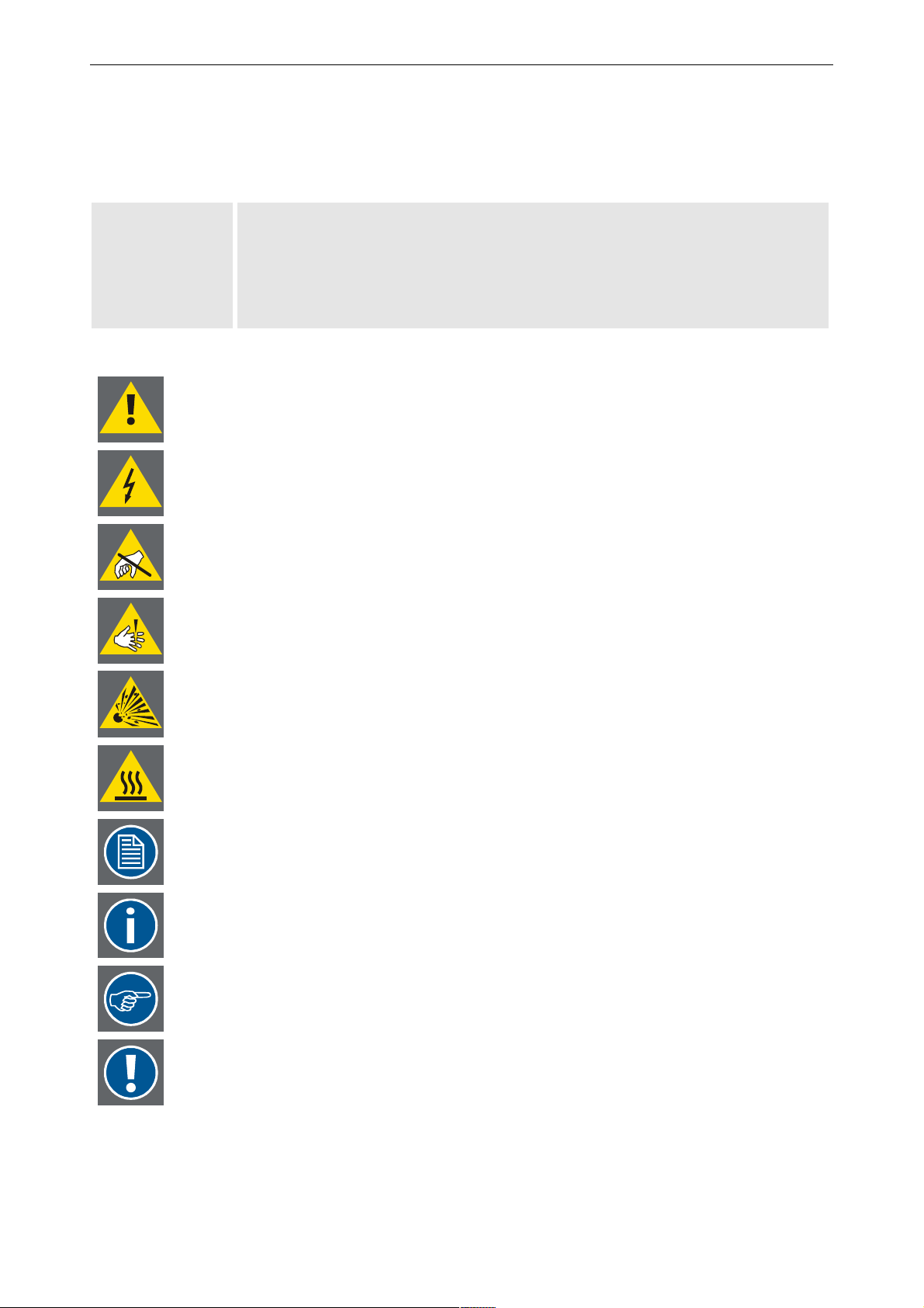
The typographic styles and the symbols used in this document have the following meaning:
Bold Labels, menus and buttons are printed in Bold font.
Condensed Links to both other chapters of this manual and to sites in the Internet are printed
condensed. In the on-line version of this manual all hyperlinks appear teal.
Courier Names of files and parts from programs are printed in the Courier font.
Courier bold Inputs you are supposed to do from the keyboard are printed in Courier bold font.
If you do not heed instructions indicated by this symbol there is a risk of damage to the
equipment!
If you do not heed instructions indicated by this symbol there is a risk of electrical shock
and danger to personal health!
If you do not heed instructions indicated by this symbol there is a risk of damage to parts,
which are sensitive towared electrostatic charge!
If you do not heed instructions indicated by this symbol there is a risk to get harmed by
sharp objects!
If you do not heed instructions indicated by this symbol there is a risk that parts may
explode!
If you do not heed instructions indicated by this symbol there is a risk that hot parts impact
persons or objects!
The sheet icon indicates additional notes.
Next to this icon you find further information.
This arrow marks tips.
Next to this icon you find important notes.
Barco - OverView D series - Doc-3353-2 - user's manual - Revision 04 - April 2005
________________________________________________________________________
1-3
Page 12
1. Preliminary Remarks
1.4 Safety information
This section describes safety precautions which must be observed when installing a product from Barco.
Safety
The safety standards of information technology equipment impose important requirements on the use of safety
critical components, materials and isolation, in order to protect the user or operator against the risk of electric
shock and energy hazard, and having access to live parts.
Safety standards also impose limits to the internal and external temperature rises, radiation levels, mechanical
stability and strength, enclosure construction and protection against risk of fire.
Simulated single fault condition testing ensures the safety of the equipment to the use even when the equipment’s normal operation fails.
General safety instructions
• All the safety and operating instructions should be read before using this unit.
• The operating instructions manual should be retained for future reference.
• All warnings on the device and in the documentation manuals should be adhered to.
• All instructions for operating and use of this equipment must be followed precisely.
Installation and Service
Installation and preliminary adjustments should be performed by qualified Barco personnel or authorized Barco
service dealers.
On Safety
Check the power rating on your outlet before connecting the devices to the wall outlet or
to a power strip. Contact your facilities manager or a qualified electrician if you are not
sure what type of power is supplied to your building.
The devices are designed to operate with single-phase power systems having a
grounded neutral conductor. To reduce the risk of electrical shock, do not plug into any
other type of power system.
A. Mains lead (AC Power cord) with CEE 7 plug:
The colors of the mains lead are colored in accordance with the following code:
Green-and-yellow: Earth (safety earth)
Blue: Neutral
Brown: Line (live)
Barco - OverView D series - Doc-3353-2 - user's manual - Revision 04 - April 2005
________________________________________________________________________
1-4
Page 13
1. Preliminary Remarks
B. Power cord with ANSI 73.11 plug:
The wires of the power cord are colored in accordance with the following code:
Green/yellow: Ground
White: Neutral
Black: Line (live)
• Do not allow anything to rest on the power cord. Do not locate this product where persons will walk on the
cord.
• To disconnect the cord, pull it out by the plug. Never pull the cord itself.
• If an extension cord is used with this product, make sure that the total of the ampere ratings on the products
plugged into the extension cord does not exceed the extension cord ampere rating. Also make sure that the
total of all products plugged into the wall outlet does not exceed 15 amperes.
• Never push objects of any kind into this product through cabinet slots as they may touch dangerous voltage
points or short out parts that could result in a risk of fire or electrical shock.
• Never spill liquid of any kind on the product. Should any liquid or solid object fall into the cabinet, unplug the
set and have it checked by qualified service personnel before resuming operations.
Warning: Do Not Place Flammable or Combustible Materials Near Projector!
Barco products are designed and manufactured to meet the most stringent safety regulations. Exposing flammable or combustible materials into close proximity of this device could result in the spontaneous ignition of that
material, resulting in a fire. For this reason, it is absolutely necessary to leave an "exclusion zone" around all
external surfaces of the projector whereby no flammable or combustible materials are present. The exclusion
zone must be not less than 10 cm (4"). Do not cover the projector with any material while the projector is in
operation.
Keep flammable and combustible materials away from the projector at all times. Mount the projector in a well
ventilated area away from sources of ignition and out of direct sun light. Never expose this product to rain or
excessive moisture. In the event of fire, use sand, CO
electrical fire.
, or dry powder fire extinguishers; never use water on an
2
Always have service performed on this product by authorized Barco service personnel. Always insist on genuine
Barco replacement parts. Never use non-Barco replacement parts as they may degrade the safety of this device.
Use only the power cord supplied with your device. While appearing to be similar, other power cords have not
been safety tested at the factory and may not be used to power the projector. For a replacement power cord,
contact your dealer.
Slots and openings in the cabinet and the sides are provided for ventilation; to ensure reliable operation of the
device and to protect it from overheating, these openings must not be blocked or covered. This product should
never be placed near or over a radiator or heat register. This product should not be placed in a built-in installation or enclosure unless proper ventilation is provided.
Barco - OverView D series - Doc-3353-2 - user's manual - Revision 04 - April 2005
________________________________________________________________________
1-5
Page 14
1. Preliminary Remarks
On Servicing
Do not attempt to service this device yourself, as opening or removing covers may expose you to dangerous
voltage potential and risk of electric shock! Refer all projector service to a qualified Barco service center.
Adjust only those controls that are covered by the operating instructions since improper adjustment of the other
controls may result in damage and will often require extensive work by a qualified technician to restore the
product to normal operation.
Call for service in the following conditions :
• When the power cord or plug is damaged or frayed.
• If liquid has been spilled into the device.
• If the product has been exposed to rain or water.
• If the product does not operate normally when the operating instructions are followed.
• If the product has been dropped or the cabinet has been damaged;
• If the product exhibits a distinct change in performance, indicating a need for service.
When replacement parts are required, be sure the service technician has used original Barco replacement parts
or authorized replacement parts which have the same characteristics as the Barco original part. Unauthorized
substitutions may result in degraded performance and reliability, fire, electric shock or other hazards. Unauthorized substitutions may void warranty.
Upon completion of any service or repairs to this unit, ask the service technician to perform safety checks to
determine that the unit is in proper operating condition.
1.4.1 Precautions
For your own protection, observe the following safety precautions when installing your device!
• Observe all warnings and instructions printed on the devices!
• Check that the voltage and frequency of your power supply match those printed on the device label with the
rated electrical values!
• Servicing not explicitly mentioned in this manual should never be carried out by unauthorized personnel!
1.4.2 Unpacking of devices
Note advises on the packaging for unpacking!
1.4.3 Modification of devices
Mechanical or electrical modifications others than described in this manual must not be made to the devices.
Barco is not liable for damages resulting from modified devices.
Only authorized personnel should carry out other maintenance work not explicitly mentioned in this user's manual!
Never open the case of the power supply or of the projection unit without first disconnecting the power supply cord! Measurements and tests with an opened device may be
carried out only in the factory or by specially trained personnel, due to the dangers of
electrical shock.
Barco - OverView D series - Doc-3353-2 - user's manual - Revision 04 - April 2005
________________________________________________________________________
1-6
Page 15

2 Abbreviated summary
This chapter provides a summary of the system components and characteristics.
2. Abbreviated summary
Barco - OverView D series - Doc-3353-2 - user's manual - Revision 04 - April 2005
________________________________________________________________________
2-1
Page 16

2. Abbreviated summary
2.1 Design
OVERVIEW D is a modular rear projection system for the construction of large Display Walls. The technologies used
guarantee the best optical properties for high-quality presentation of information with very simple integration
into higher-level systems.
Although different in screen size and resolution, the various members of the OverView D family all have the
same functionalities, with one exception: projection modules with SXGA+ resolution have two digital inputs, thus
providing redundancy options, cf. Source selection
Technology
VERVIEW D combines the latest modern projection technology with sophisticated electronics and solid mechanics.
O
This design results in high image quality and reliability.
• High, constant reading accuracy over the complete display panel
Optimally adjusted high-performance lens systems guarantee a distortion-free and sharp image.
• Bright displays
A UHP™ lamp provides a high luminous flux, which is passed on at great efficiency by the illumination system. (UHP is a trademark of Philips Electronics N.V.). Depending on the requirements, the illumination unit
can be equipped with 100 W lamps or 120 W lamps.
• Dual lamp system
The projection engines has a dual lamp system and can be operated in three operation modes: hot standby,
cold standby, auto switch mode.
In hot standby both lamps are on. In case of a lamp failure, the light output of the other lamp is immediately switched to illuminate the optics, and there is no noticeable effect on the displayed information: no
loss of information, no impact on quality. Switching time is about half a second.
In cold standby mode the second lamp is only switched on in case a failure occurs with the active lamp.
Since the second lamp needs some minutes to reach a stable operating temperature, at the beginning the
display will have reduced brightness. The contents of information, however, is available nearly without any
interrupt.
Auto switch mode is a special version of the cold standby mode: the lamps are active in turns: after a defined period, the light path is illuminated by the other lamp. Since the lamp is switched on some minutes in
advance, the takeover of the second lamp is nearly not noticeable. The cycle time can be set between
12 hours and 500 hours.
• High contrast
The screen has a surface which absorbs ambient light falling on it and increases the contrast.
• Electromagnetic immunity
Because of the digital projection technologies and their direct digital control O
VERVIEW D guarantees highest
possible immunity against electromagnetic interference.
User friendly
The rear panel of an O
VERVIEW projection cube gives free access to all control elements. The only maintenance
work, i. e. replacing the filter pad and the lamps, can be done within few seconds and makes no re-adjustment
necessary.
Because of the digital projection technologies and their direct digital control, the display is largely flicker-free and
therefore ergonomic.
Environmentally friendly
The burning life of the used lamps is very high. This long lamp lifetime and the low power consumption do not
only reduce the cost of ownership but also contribute to saving energy and natural resources.
Barco - OverView D series - Doc-3353-2 - user's manual - Revision 04 - April 2005
________________________________________________________________________
2-2
Page 17
2. Abbreviated summary
Flexible configuration
O
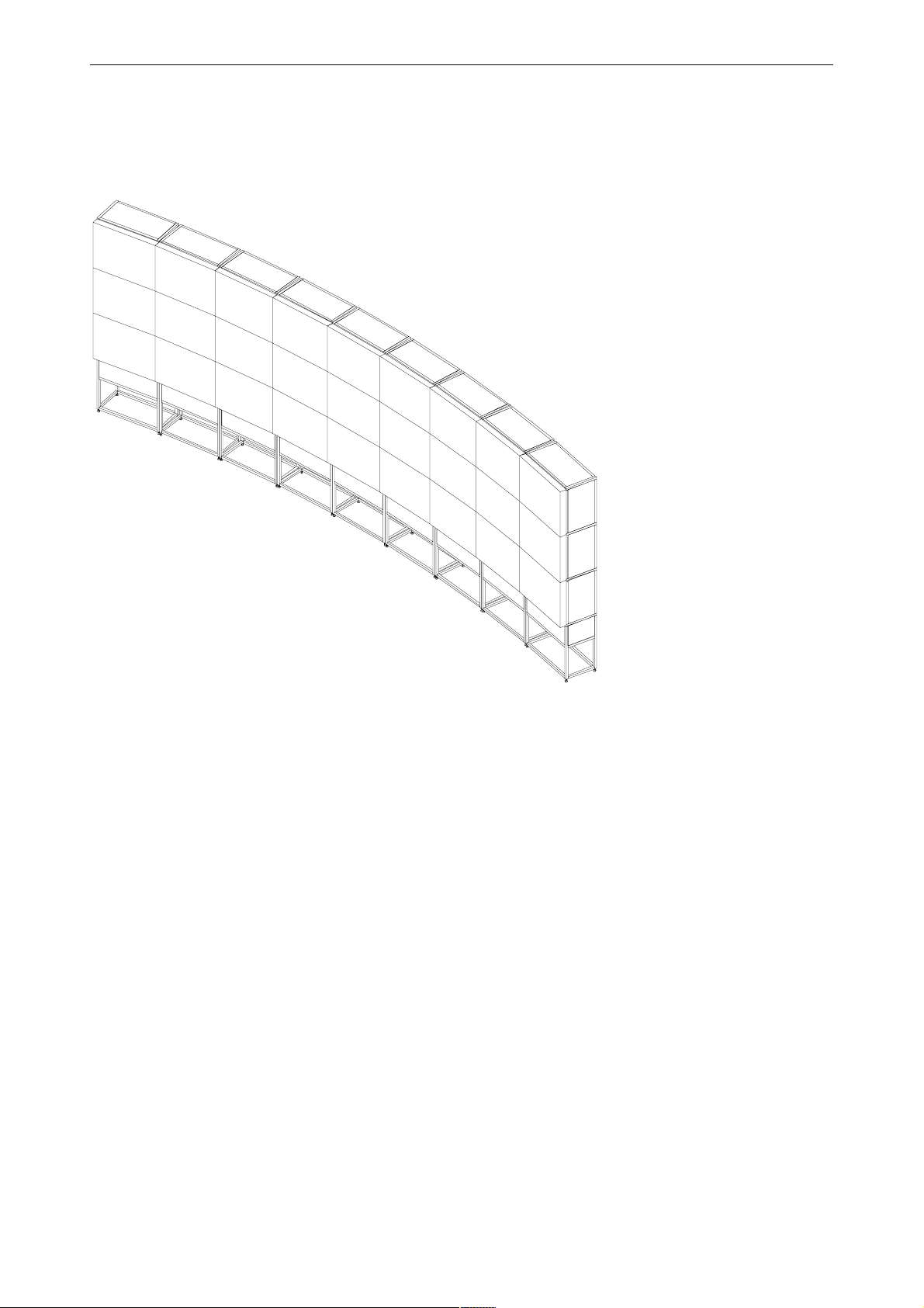
VERVIEW D projection modules can be combined in rows and columns to realize Display Walls of virtually unlim-
ited size. The setup of the projection modules can be linear or curved.
Curved Display Wall consisting of 9x3 OverView cDG67-DL projection modules
Figure 2-1
Barco - OverView D series - Doc-3353-2 - user's manual - Revision 04 - April 2005
________________________________________________________________________
2-3
Page 18
2. Abbreviated summary
2.2 Components of an OverView D display wall
An OVERVIEW D display wall consists of two main components: the projection modules housing the dual lamp projector and the graphical controller.
2.2.1 Projection module
The projection module is the component for generating the displays of OVERVIEW D The light of a UHP™ lamp is
directed via an optical system to a Digital Mirror Device whose image is projected via a high-performance lens
system onto the rear side of a screen.
Due to the dual lamp system, the availability of the Display Wall is about 100%: in case the lamp fails, the light
output of the second lamp is automatically switched into the light path.
Since the screen is illuminated right up to its edges, it is possible to construct Display Walls of any size by the
adjacent arrangement of several units.
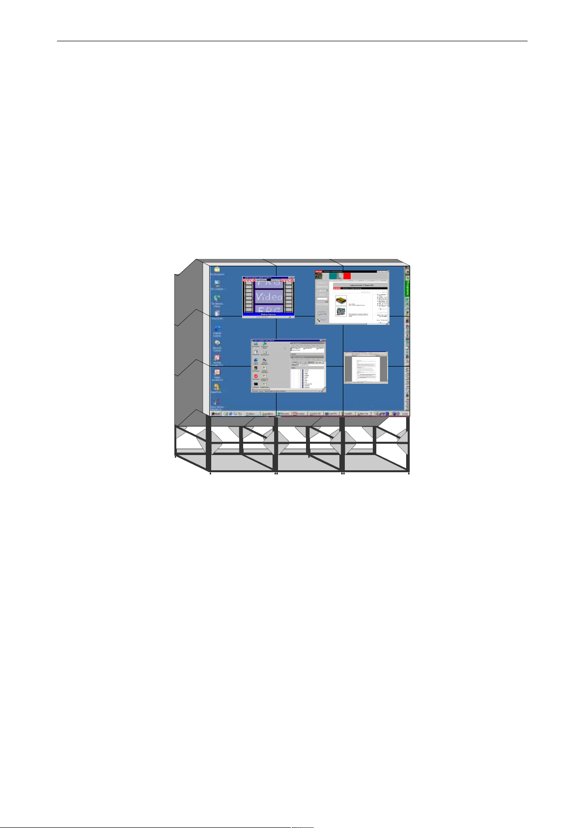
Display Wall consisting of 9 OverView mDG50-DL projection modules
Barco - OverView D series - Doc-3353-2 - user's manual - Revision 04 - April 2005
Figure 2-2
________________________________________________________________________
2-4
Page 19
2. Abbreviated summary
2.2.2 GRAPHICAL CONTROL UNIT
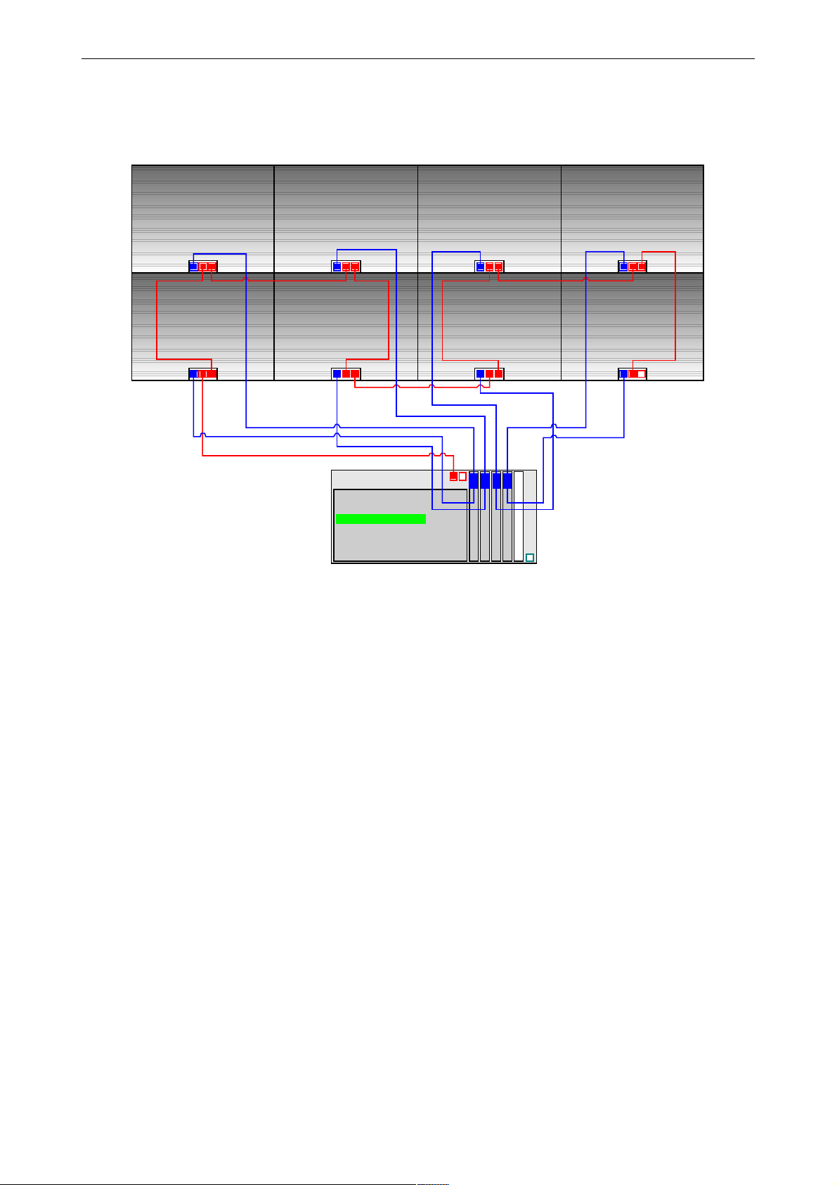
The projection unit of OVERVIEW D is provided with display information from the graphical control unit.
Module1x1
Ov erView D
Module2x1
Ov erv iew D
Module1x2
Ov erv iew D
Module2x2
Ov erv iew D
Desktop-Server
SNMP-Manager
APOLLO-Base
DeviceCMD
SNMP-Agent BarcoR C
EOS
Module1x3
Ov erv iew D
Module2x3
Ov erv iew D
OVT di gital
OVT di gital
OVT di gital
OVT di gital
EOS
the controller
Module1x4
Ov erv iew D
Module2x4
Ov erv iew D
Figure 2-3
provides the Display Wall with data
Barco - OverView D series - Doc-3353-2 - user's manual - Revision 04 - April 2005
________________________________________________________________________
2-5
Page 20

3. Design and functions
3 Design and functions
This section provides a technical description of the equipment listing the fundamental characteristics and functional principles.
Barco - OverView D series - Doc-3353-2 - user's manual - Revision 04 - April 2005
________________________________________________________________________
3-1
Page 21
3. Design and functions
3.1 Projection module
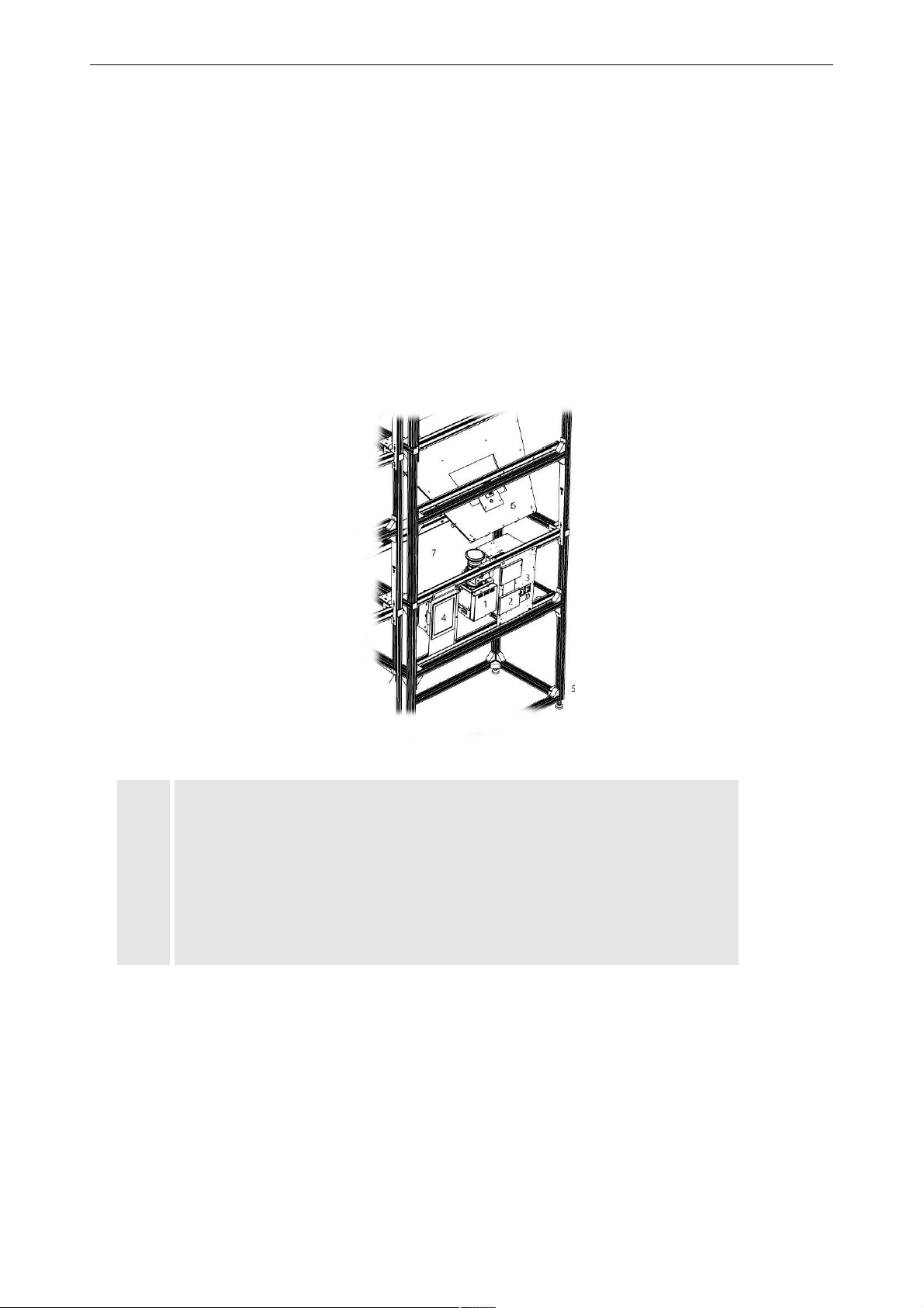
Depending on the screen size, OverView D is designed as a dark box mounted on a support, or as a flexible
structure with shieldings. The differences in design are only mechanical, optics and electronics do not differ.
Especially care is taken that no ambient light is falling onto the rear of the screen thus reducing the contrast.
Inside the projection module, the following components are installed: the projection unit with the a single-DMD™
chip, color filter system, illumination and projection optics, the illumination unit (dual lamp system), and a cooling system.
Via a mirror, the image is projected onto the rear of the screen.
1 Projection Unit
2 Illumination system (dual lamp system)
3
Power block
4 Filter
5 Structure
6 Mirror
7 Screen
• Dual lamp system
The illumination unit can be selected as a 100W model or a 120W model, depending on the overall need of
brightness or power consumption.
The light of a UHP™ lamp illuminates via a transmissive color wheel the DMD.
The projection engines has a dual lamp system and can be operated in three operation modes: Hot Standby,
Cold Standby, Auto Switch mode.
Barco - OverView D series - Doc-3353-2 - user's manual - Revision 04 - April 2005
________________________________________________________________________
Figure 3-1
3-2
Page 22

3. Design and functions
• In Hot Standby both lamps are on. In case of a lamp failure, the light output of the other lamp is immedi-
ately switched to illuminate the optics, and there is no noticeable effect on the displayed information: no
loss of information, no impact on quality. Switching time is about half a second.
In Cold Standby mode the second lamp is only switched on in case a failure occurs with the active lamp.
Since the second lamp needs about one minute to reach a stable operating temperature, at the beginning
the display will have reduced brightness. The contents of information, however, is available nearly without
any interrupt.
Auto Switch mode is a special version of the cold standby mode: the lamps are active in turns during a selectable cycle time. Alternatingly the light path is illuminated by Lamp top or lamp bottom. Since the lamp is
switched on some minutes in advance, the takeover of the other lamp is nearly not noticeable. The cycle
time can be set between 12 hours and 500 hours.
• Color wheel
The color wheel consists of four segments, one for red, green, blue and white. For XGA and SXGA resolution,
it spins at triple speed (178 Hz), for SXGA+ resolution it spins at double speed.
• DMD
A Digital Micromirror Device (DMD™) is an array of tiny, tiltable mirrors, each of which corresponds to an individual pixel. The mirrors are orientated by applying an electrical signal and can take up alternatively two
positions: tilted +12° (+10°) and -12° (.10°). If they are in the +10° position light is reflected to the screen,
otherwise it is reflected away. The tilting angle as well as the dimenesion of the DMD chips and the number
of active mirrors depends on resolution.
DMD is a trademark of Texas Instruments Incorporated.
• Electronics
The electronics comprises graphics and video signal processing electronics as well as the functionality to
control the projection engine.
The electronics converts the image signals of the graphic card into control signals for the DMD’s. The image is
electronically mirrored in the process and the reversal of the image following the deflection mirror is thus
compensated.
• Data cable
The digital display information is transmitted via a cable directly from the controller
to the DMD control elec-
tronics.
• Lens system
The projection lens system has been especially developed for O
VERVIEW D. It projects the image resulting of
the DMDs via the deflection mirrors onto the rear of the screen module.
• Fan
A fan in the housing ensures that the unit is sufficiently cooled. A second fan positioned beneath the lamp
lift optimizes the air circulation.
• Deflection mirror
Due to folding up the optical path by a mirror the installation depth of the O
VERVIEW D projection unit is ex-
ceptionally small.
Barco - OverView D series - Doc-3353-2 - user's manual - Revision 04 - April 2005
________________________________________________________________________
3-3
Page 23
3. Design and functions
3.2 Screen
The image is generated in the screen.
Fresnel lens
The screen consists of a Fresnel lens and a Front Element Screen. The Fresnel lens deflects the light coming from
the projection lens system such that it falls perpendicularly onto the front element screen.
Front element
The front element screen guarantees that the light is distributed horizontally and vertically, while maintaining a
high contrast.
Texture of surface
The surface of the screen has a special non-glare texture. This texture minimizes the direct reflection of the light
of the surrounding and contributes also to the high contrast of the screen.
3.3 Principle of DMD projection technology
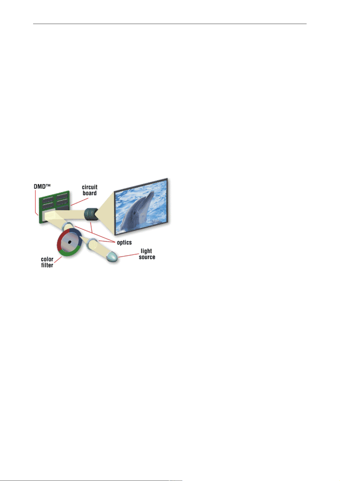
For a one-chip projection system, the DMD is sequentially illuminated with the three primary colors, red, green,
and blue (RGB)
principle of a single-chip DLP projection system
Figure 3-2
A condenser lens collects the light, which is imaged onto the surface of a transmissive color wheel. A second lens
collects the light that passes through the color wheel and evenly illuminates the surface of the DMD. Depending
on the rotational state of the mirror (+12 or -12 degrees), the light is directed either into the pupil of the projection lens (on) or away from the pupil of the projection lens (off). The projection lens has two functions: (1) to
collect the light from each on-state mirror, and (2) to project an enlarged image of the mirror surface to a projection screen.
The example shows a color wheel with three segments red, green, and blue. It is also possible that the segments
for the primaries exist twice (RGBRGB), or that a white segment is added (RGBW).
Barco - OverView D series - Doc-3353-2 - user's manual - Revision 04 - April 2005
________________________________________________________________________
3-4
Page 24
3. Design and functions
3.4 Principle of dual lamp system
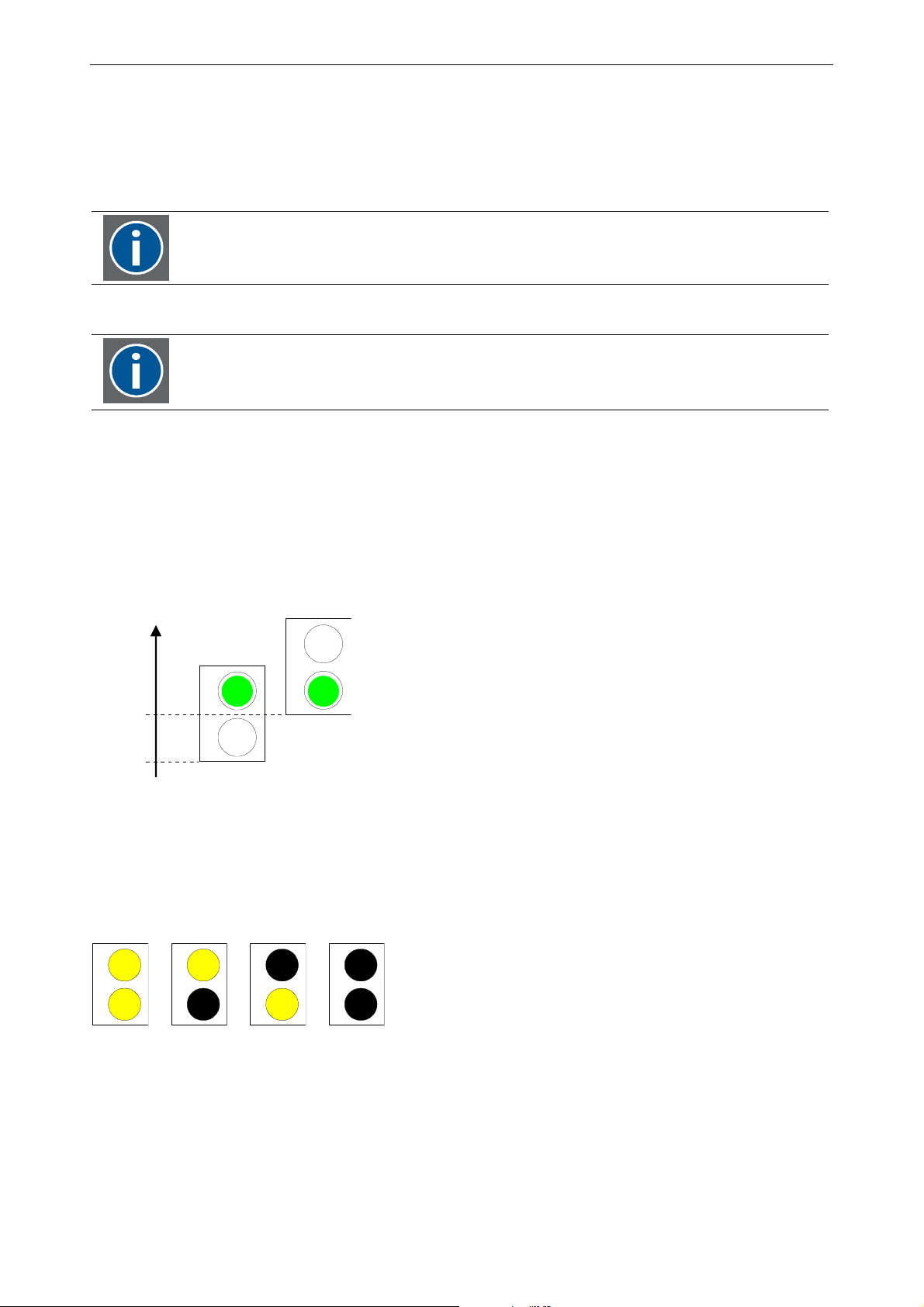
The dual lamp system implemented in OverView D is based on a lamp lift which moves the respective lamp in
front of the stationary optics.
The lamps are moveable
The optics is stationary
The following identies apply:
Lamp Top == L1
Lamp Bottom == L2
The lift is the carrier of the lamps and can have two positions: lift up and lift down.
If the lift is in the down position,
the top lamp (Lamp1, L1, Lamp Top) is coupling light into the optical system (P)
If the lift is in the up position,
the bottom lamp (Lamp2, L2, Lamp Bottom) is coupling light into the optical system (P)
Liftposition
L1
L1
P
up
L2
down
L2
P
Since there are two lamps, the dual lamp system can have four states:
L1 on, L2 on,
L1 on, L2 off,
L1 off, L2 on,
L1 off, L2 off
L1
L1
L1
L1
Figure 3-3
Lift positions
L2
L2
L2
L2
Barco - OverView D series - Doc-3353-2 - user's manual - Revision 04 - April 2005
Figure 3-4
Lamp states
________________________________________________________________________
3-5
Page 25
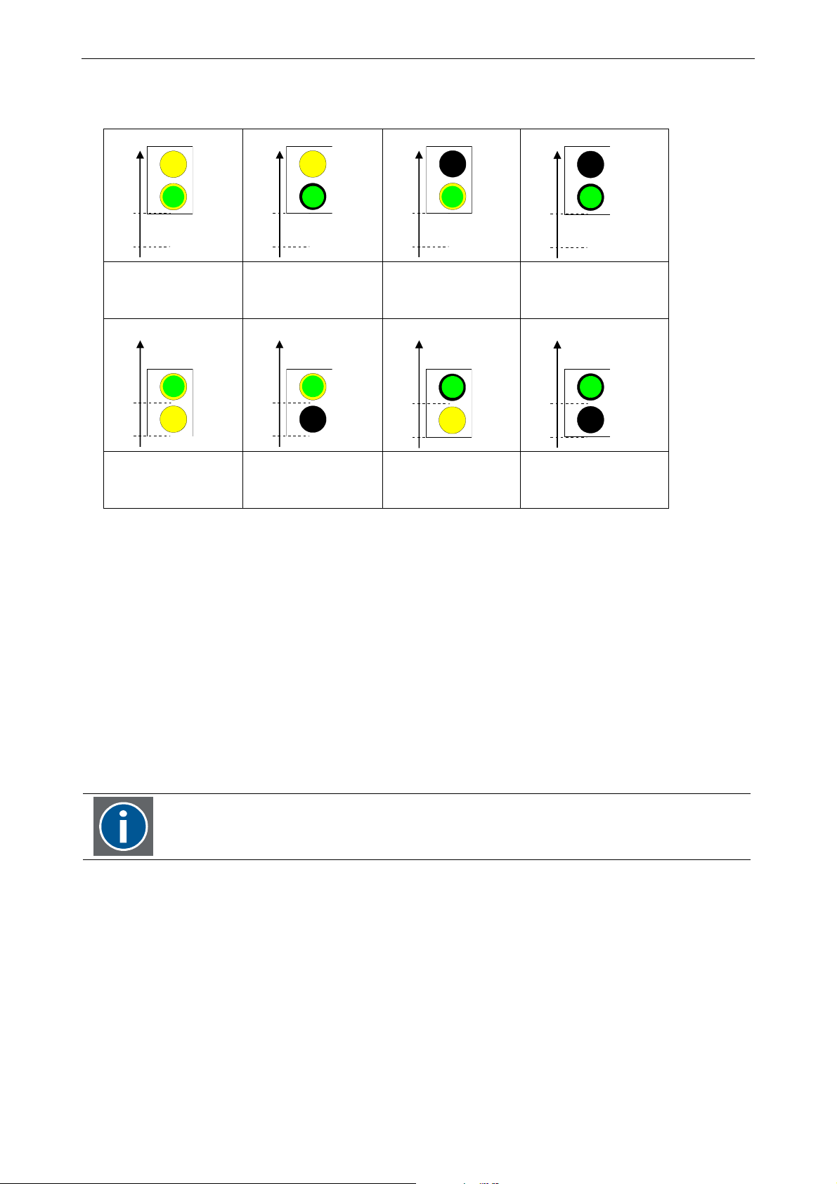
Each of this states can be combined with one of the lift positions:
3. Design and functions
Liftposition
up
down
L1
P
L2
Liftposition
up
down
L1
P
L2
Hot standby Hot standby,
moment of lamp
failure
Liftposition
up
down
P
L1
L2
Liftposition
up
down
P
L1
L2
Hot standby Cold standby /
Auto switch
Liftposition
L1
P
L2
up
down
Cold standby /
Auto switch
Liftposition
P
L1
up
L2
down
Hot standby,
moment of lamp
failure
Liftposition
L1
P
L2
up
down
Both lamps are
switched off,
projector in standby
Liftposition
P
L1
up
L2
down
Both lamps are
switched off
projector in standby
Lamp states and lift position
Figure 3-5
The lamp which output illuminates the optics is called active lamp.
In Hot Standby mode, both lamps are switched on.
In Cold Standby mode (or Auto Switch mode), the active lamp is switched on, the second lamp is switched off.
In projector standby mode, both lamps are switched off.
The status of the projector and of the lamps can be checked by means of the status LEDs on the rear panel of the
projection module, cf. Manual user interface.
The operation mode (Hot Standby, Cold Standby, Auto Switch) can be selected via the IR Remote Control Unit, cf.
Mode.
Hot Standby is only available if especially requested!
The active lamp can be selected via the IR Remote Control Unit (RCU) cf. Active lamp. (When servicing and while
standing behind the projection module, the active lamp can also be selected via the manual user interface, cf.
Manual user interface).
Barco - OverView D series - Doc-3353-2 - user's manual - Revision 04 - April 2005
________________________________________________________________________
3-6
Page 26
3. Design and functions
3.5 Filter for changing the color temperature (backdrop applications)
OverView D projection systems usually are operated at a color temperature of 6500K (daylight). In broadcast
application it might be required to have the color temperature reduced to 3200 K (reddish). Studios are often
lighted by electrically-generated tungsten light. This light has typically a color temperature of 3200K (reddish).
The cameras are adjusted to this color temperature and show "normal daylight" (6500K) images on TV. In consequence incoming daylight at 6500K or projection systems generation 6500 K will appear blue. Therefore the
display wall has to be set to the same color temperator the cameras are adjusted to in order to be viewed "under normal daylight conditions" on TV.
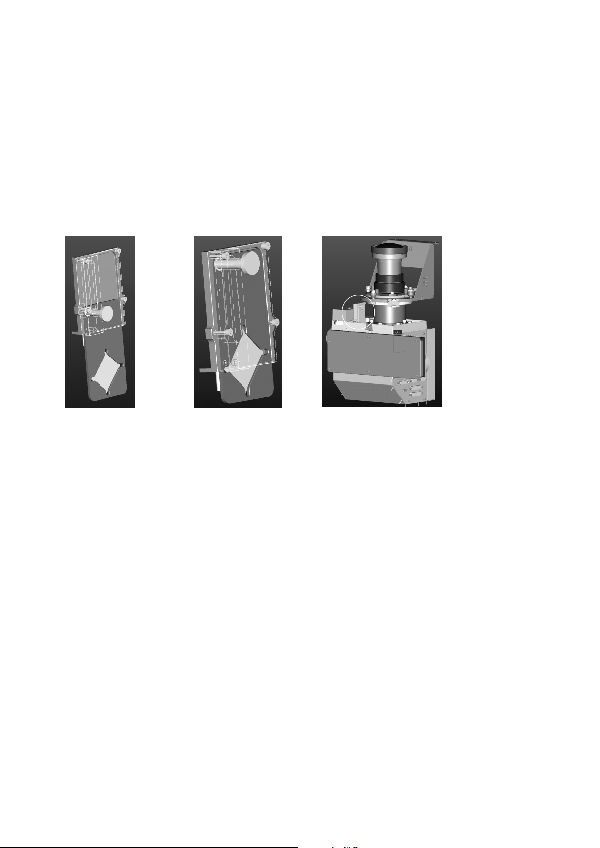
The XGA projection unit of the OverView D series can be completed by a filter changing the color temperature
from 6500K to 3200K. This filter can be put in placed when required and ensures that cameras adjusted to 3200K
record "normal daylight" when recording the display wall.
Filter active (3200K) Filter inactive (6500K) Projection unit with 3200K filter cartridge
However, the light output of the projection systems with a 3200K filter is about only 58% of the light output of
6500K systems: the lamp employed in the OverView D series have a very small share in the red part of the
spectral range.
Due to the field of application, this filter is only available for XGA resolution: cameras work even at lower resolution.
To compensate the reduction in light output, the projection system can be equipped with a dual lamp illumination unit which houses 2x200W VIP200 lamps.
Barco - OverView D series - Doc-3353-2 - user's manual - Revision 04 - April 2005
________________________________________________________________________
3-7
Page 27
3. Design and functions
3.6 Options for the OverView D series: lamps and color temperature filter
For the OverView D series, there are three different illumination unit which employ 2x100W lamp, 2x120W lamp,
2x200W lamp, respectively. All three of them produce "daylight" at a color temperature of 6500K.
A color filter is available to adjust the color temperature to 3200K.
Whereas all systems can be employed with an illumination unit with 100W or 120W respectively, it's only the
systems with XGA resolution which are available with an illumination unit 200W and a 3200K/6500K color filter
cartridge.
Please keep in mind that the 3200K color filter reduces the amount of light of about
50%. So it is not recommended to use it with 100W lamps, although it technically could
be done.
The ideal illumination unit to employ the 3200K color filter is the 200W illumination
unit.
This combination is usually intended for backdrop applications (broadcast).
Options for OverView DG (XGA)
Option 50" 67" 80"
Illumination unit 120W ; ; ;
Illumination unit 100W ; ; ;
Illumination unit 200W ; ;
Filter cartridge 6500K/3200K
(only in conjunction with 200W or 120W illumination unit)
Options for OverView DR (SXGA) and OverView DR+ (SXGA+)
Option 50" 67" 80"
Illumination unit 120W ; ; ;
Illumination unit 100W ; ; ;
; ;
Barco - OverView D series - Doc-3353-2 - user's manual - Revision 04 - April 2005
________________________________________________________________________
3-8
Page 28
3. Design and functions
3.7 Operation elements
Control Elements
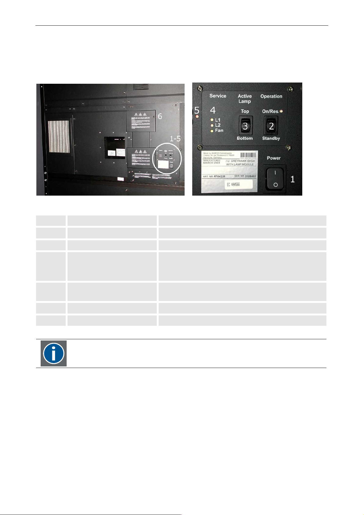
The control elements of OverView D are located on the rear of the system. They include 3 switches and in total 6
LEDs.
rear side: control elements
Item Refers to Function
1 Power switch Rocker switch, Power ON (up) or OFF (down)
2 Standby switch and Power LED also used for the acknowledge of errors (reset)
3 Active lamp selection switch Rocker switch,
top: select lamp top, (lamp 1)
bottom: select lamp bottom (lamp 2)
4 Status LEDs
(L1, L2, Fan)
Informs about the operation status of the two lamps and the
fan
5 Lamp door bottom LED indicates if the lamp door may be opened or not
6 Lamp door top LED indicates if the lamp door may be opened or not
The operation via the control elements on the rear side (manual user interface) is intended for
servicing purposes only!
The switches and LEDs are described in chapter Manual user interface
Figure 3-6
Remote-Control
Each OverView D projection module can be controlled by a serial interface or by an IR control unit (IR RCU)
Barco - OverView D series - Doc-3353-2 - user's manual - Revision 04 - April 2005
________________________________________________________________________
3-9
Page 29

3. Design and functions
3.8 Controller
The projection units of an OVERVIEW D Display Wall are provided with display information by the controller. The
controller is available as a standard X-Terminal with exceptional additional properties or as a Windows
NT/2000/XP Workstation.
3.8.1 Controller as X.11 Terminal
The X Window System (also abbreviated to X.11) was originally developed by MIT as a graphic system for UNIX
workstations. In the meantime, it is available on a large number of computer platforms. These also include operating systems such as VAX/VMS or OS/2 in addition to various UNIX versions.
The X Window System is divided into two parts: The X client and X server are connected to one another by a
communication system (usually TCP/IP). This division permits execution of the X server and X client either on the
same system or also on different systems connected by a network.
The X server is executed on the controller. It implements the graphic display and handles the inputs from the
keyboard and mouse. The X clients can be executed also on the controller or on other systems in the network.
The controller satisfies the X.11 protocol (Rel. 6.), and can thus be used by any X clients, toolkits and window
managers. All X clients (including window managers) use the multi-screen facility without actually 'knowing' this.
Video and RGB Input
The controller has inputs to which video cameras or recorders as well as monitor signals can be connected.
Simple Integration
The controller possesses the generally established interfaces (Ethernet, TCP/IP, X.11 protocol), thus guaranteeing
simple integration into existing computer networks.
Blinking
The controller provides blinking colors (frequencies to DIN).
3.8.2 Controller as Windows NT/ Windows 2000 / Windows XP workstation
If applications based on Microsoft Windows NT or Windows 2000 / Windows XP should be operated via OVER-
VIEW D, the controller as Windows NT/2000/XP Workstation is used. The operating system in this case is Windows
NT 4.0, Windows2000, or Windows XP, so O
connected to a large monitor. No software modifications are necessary to run applications on O
The Windows applications are operated by keyboard and mouse of the controller.
Video and RGB Input
The controller has inputs to which video cameras or recorders as well as monitor signals can be connected.
VERVIEW D is like a PC with Windows NT/Windows2000/Windows XP
VERVIEW D.
Barco - OverView D series - Doc-3353-2 - user's manual - Revision 04 - April 2005
_______________________________________________________________________
3-10
Page 30

4 Operation
This section describes the operation of OVERVIEW D.
4. Operation
Barco - OverView D series - Doc-3353-2 - user's manual - Revision 04 - April 2005
________________________________________________________________________
4-1
Page 31
4. Operation
4.1 Cabling
All necessary cables are connected to the OVERVIEW D projection module.
4.1.1 Power
Check the power rating on your outlet before connecting the projection modules to the
wall outlet or to a power strip. Contact your facilities manager or a qualified electrician if
you are not sure what type of power is supplied to your building.
The devices are designed to operate with single-phase power systems having a
grounded neutral conductor. To reduce the risk of electrical shock, do not plug into any
other type of power system.
4.1.2 Data
The projection units of an OVERVIEW D Display Wall are connected to the graphic cards of a Barco Controller. The
projector as a DVI interface.
Projection modules with SXGA+ resolution feature two DVI inputs, thus allowing to
connect two sources simultaneously. The source to be displayed then is selected vie the
OSD, as well as the behavior in case a source fails, cf. Source selection
Barco - OverView D series - Doc-3353-2 - user's manual - Revision 04 - April 2005
________________________________________________________________________
4-2
Page 32
4.1.3 Switching-on and –off power
The projector is switched manually using the power switch [1] located at the rear of the system.
Before switching off (disconnecting from the mains) make sure that the projector is in
standby mode! Never switch off the power switch when the projector is running!
Otherwise settings of the projector which have been changed shortly before mains switch
off might be lost.
4.2 Switching on and off the lamps
4.2.1 Switching on the lamps
Proceed as follows to ignite the lamps:
• Make sure that the projector is switched on.
• Switch on the lamp by pressing the standby key on the IR REMOTE-CONTROL for less than one second.
After ignition of the lamp it becomes gradually bright until it burns stable.
4. Operation
The equipment has a switch-off delay function which prevents the lamp from being switched off
within a period of 30 seconds.
4.2.2 Switching off the lamps
• Switch off the lamp by pressing the standby key on the IR REMOTE-CONTROL for more than one second.
Following switching-off, a switch-on delay function prevents a re-ignition for 30 seconds.
Switching the projector to and from standby as well as selecting the active lamp is done via the OSD.
When servicing, these actions can also be performed using the manual user interface on the rear of the system,
cf. Manual user interface.
Barco - OverView D series - Doc-3353-2 - user's manual - Revision 04 - April 2005
________________________________________________________________________
4-3
Page 33

5 Controlling
5. Controlling
Barco - OverView D series - Doc-3353-2 - user's manual - Revision 04 - April 2005
________________________________________________________________________
5-1
Page 34
5. Controlling
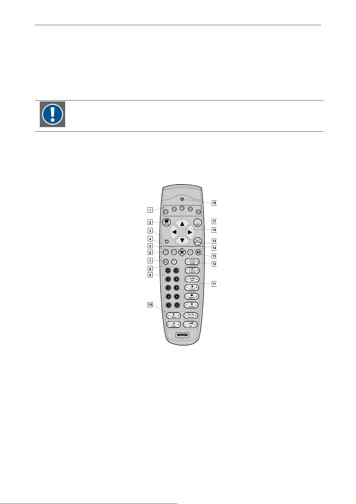
5.1 Remote control
The projector can be RS232 remote-controlled or by the IR remote control unit (RCU)
How to use the RCU?
Point the front of the RCU directly at the screen.
When using the wireless remote control, make sure you are within the effective operating distance (30m, 100ft in a straight line). The remote control unit will not function properly if strong
light strikes the sensor window or if there are obstacles between the remote control unit and
the IR sensor.
Remote Control Unit
The remote control unit (RCU) includes a battery powered infrared (IR) transmitter that allows the user to control
the projector remotely.
IR Remote Control Unit (RCU)
Figure 5-1
The remote control is used for control, adaptation and set up. It includes automatic storing of the picture controls
(brightness, contrast ...) and the settings. Use the RCU to switch between standby and operational mode.
Barco - OverView D series - Doc-3353-2 - user's manual - Revision 04 - April 2005
________________________________________________________________________
5-2
Page 35
5.2 Terminology of the RCU controls
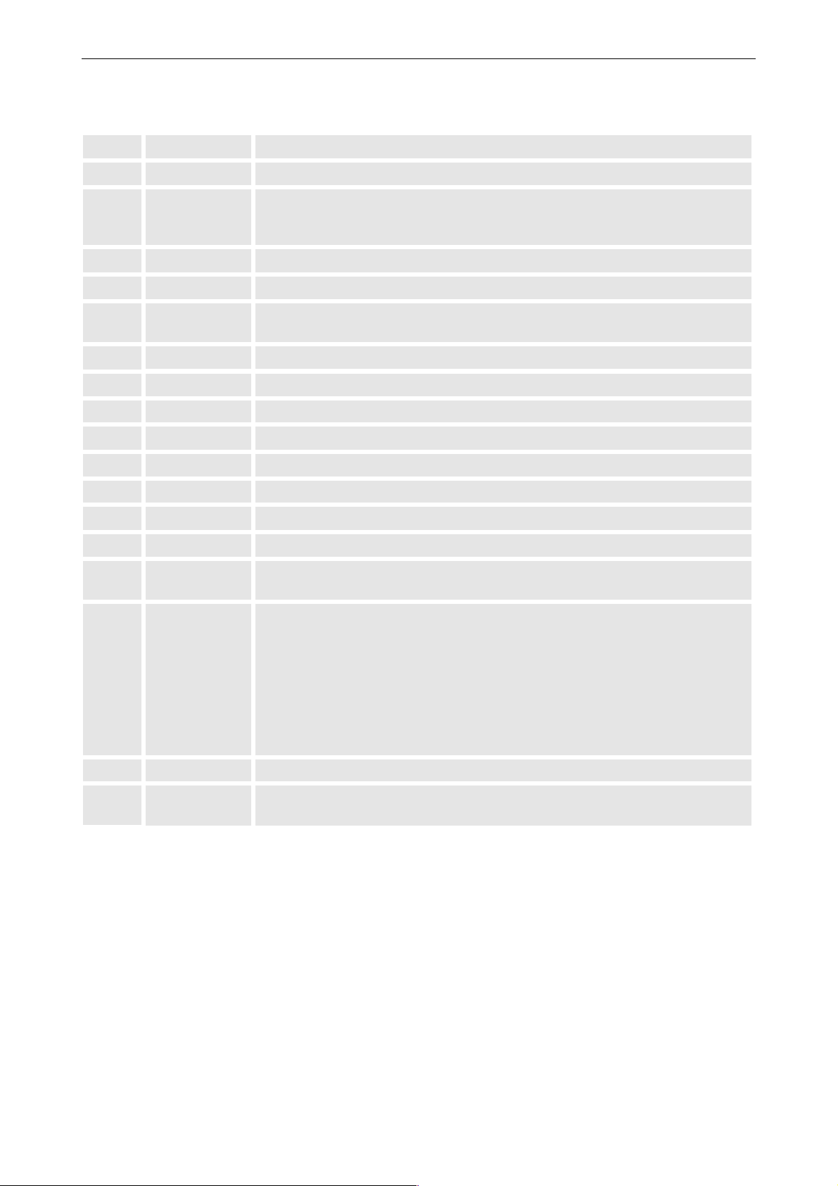
1 Function keys have no function for this projector
2 ADJ ADJUST key, to enter or exit the adjustment mode.
5. Controlling
3 Address key
(recessed key), to enter the address of the projector (between 0 and 9). Press the
recessed address key with a pencil, followed by pressing one digit button between 0 and 9.
4 Selection key has no function for this projector
5 PAUSE has no function for this projector
6 Standby
stand by button, to start projector when the power switch is switched on and to
switch off the projector without switching off the power switch.
7
Mute has no function for this projector
8 Help has no function for this projector
9 Digit buttons To enter the remote control address
10 Audio controls have no function for this projector
11 Picture controls Except for brightness and contrast, these keys have no function for this projector
12 PHASE has no function for this projector
13 Freeze has no function for this projector
14 TEXT has no function for this projector
15 ENTER
to start up the adjustment mode or to confirm an adjustment or selection in the
adjustment mode.
16 Cursor Keys to make menu selections when in the adjustment mode.
RCU
cursor key up
cursor key down
cursor key right
cursor key left
Use the cursor keys up or right for increasing a value.
Use the cursor keys down or left for decreasing a value.
17 EXIT to leave the adjustment mode or to scroll upwards when in the adjustment mode.
18 RC operating
indication
lights up when a button on the remote control is pressed. (This is a visual indicator
to check the operation of the remote control)
Barco - OverView D series - Doc-3353-2 - user's manual - Revision 04 - April 2005
________________________________________________________________________
5-3
Page 36
5. Controlling
5.3 Projector address
The projector's address may be set to any value between 0 and 255 (see 'projector address' in chapter 'Service
mode). When the address is set, the projector can be controlled now by the RCU for addresses between 0 and 9.
The projector can also be controlled by computer, e.g. IBM PC (or compatible), Apple MAC, etc. for addresses
between 0 and 255.
A projector will respond to a RCU set to an address of '0' regardless of what address is set in
the projector itself.
5.3.1 Using the RCU
The RCU is default programmed with address 0, 'zero address'. With that 'zero address' programmed into the
RCU, every projector, without exception will listen to the commands given by this RCU. If it is necessary to control a specific projector, than enter the projector address into the RCU (only when that address is between 0 and
9). The projector with the corresponding address will listen to that specific RCU.
5.3.2 Displaying a projector address
Press the ADDRESS key (recessed key on the RCU) with a pencil.
To continue using the RCU with that specific address, it is necessary to enter the same address with the digit
buttons (address between 0 and 9) within 5 seconds after pushing the address key. For example if the Address
key displays projector address 003, then press "3" digit button on the RCU to set the RCU's address to match the
projector's address. Do not press 003 digits. This will address the remote control to '0' and control all projectors in
the room.
But if you want to enter an address with two digits, e.g. 53, then you have to press “053”, otherwise the projector will accept the first digit (5) as his address.
If the address is not entered within 5 seconds, the RCU returns to its default address (zero address) and control
all projectors in the room.
5.3.3 How to program an address into the RCU?
Press the ADDRESS key (recessed key on the RCU) with a pencil and enter the address with the digit buttons
within 5 seconds after pushing the address key. That address can be any digit between 0 and 9.
Barco - OverView D series - Doc-3353-2 - user's manual - Revision 04 - April 2005
________________________________________________________________________
5-4
Page 37
5. Controlling
5.3.4 Picture controls with direct access.
If the optical dimmer has been disabled (e.g. it is broken), brightness and contrast can be controlled directly via
IR RCU. When Brightness or Contrast is pressed, a text box with a bar scale, icon and function name of the control, e.g. ’brightness...’ appears on the screen (only if Textbox in the Installation menu is ON). The length of the
bar scale and the value of the numeric indication indicate the current memorized setting for this source. The bar
scale changes as the arrows on the RCU are pressed.
The picture settings are saved in the image file.
Brightness control
A correct 'brightness' setting is important for good image reproduction.
Use the + button for a higher brightness.
Use the - button for a lower brightness.
Contrast control
A correct 'contrast' setting is important for good image reproduction.
Adjust the contrast to the level you prefer, according to room lighting conditions.
Use the + button for a higher contrast.
Use the - button for lower contrast.
As soon as the optical dimmer is enabled again, these settings get invalid.
Barco - OverView D series - Doc-3353-2 - user's manual - Revision 04 - April 2005
________________________________________________________________________
5-5
Page 38

6 Menu structure
6. Menu structure
Barco - OverView D series - Doc-3353-2 - user's manual - Revision 04 - April 2005
________________________________________________________________________
6-1
Page 39
6. Menu structure
6.1 General
OVERVIEW DL has a build in "PC like" toolbar menu which allows easy access to different parameters for setting up
the projector.
The toolbar menu is activated by pressing ADJ.
Menu items which are not applicable are grayed out.
Commands which require expert knowledge are only accessible for advanced users and can be only accessed via
a password.
6.2 Menu layout
The existence of a submenu is indicated by a white arrow
Three suspension points indicate that the menu item hides a dialog box or a text box.
A dot indicates which option is selected.
Grayed out menus or items are not available in this software version.
6.2.1 Navigating
Use the cursor keys on the RCU to navigate within a menu or a submenu.
Press Enter to select a menu item
Press Enter to open the submenu.
Press Exit to exit a submenu or menu
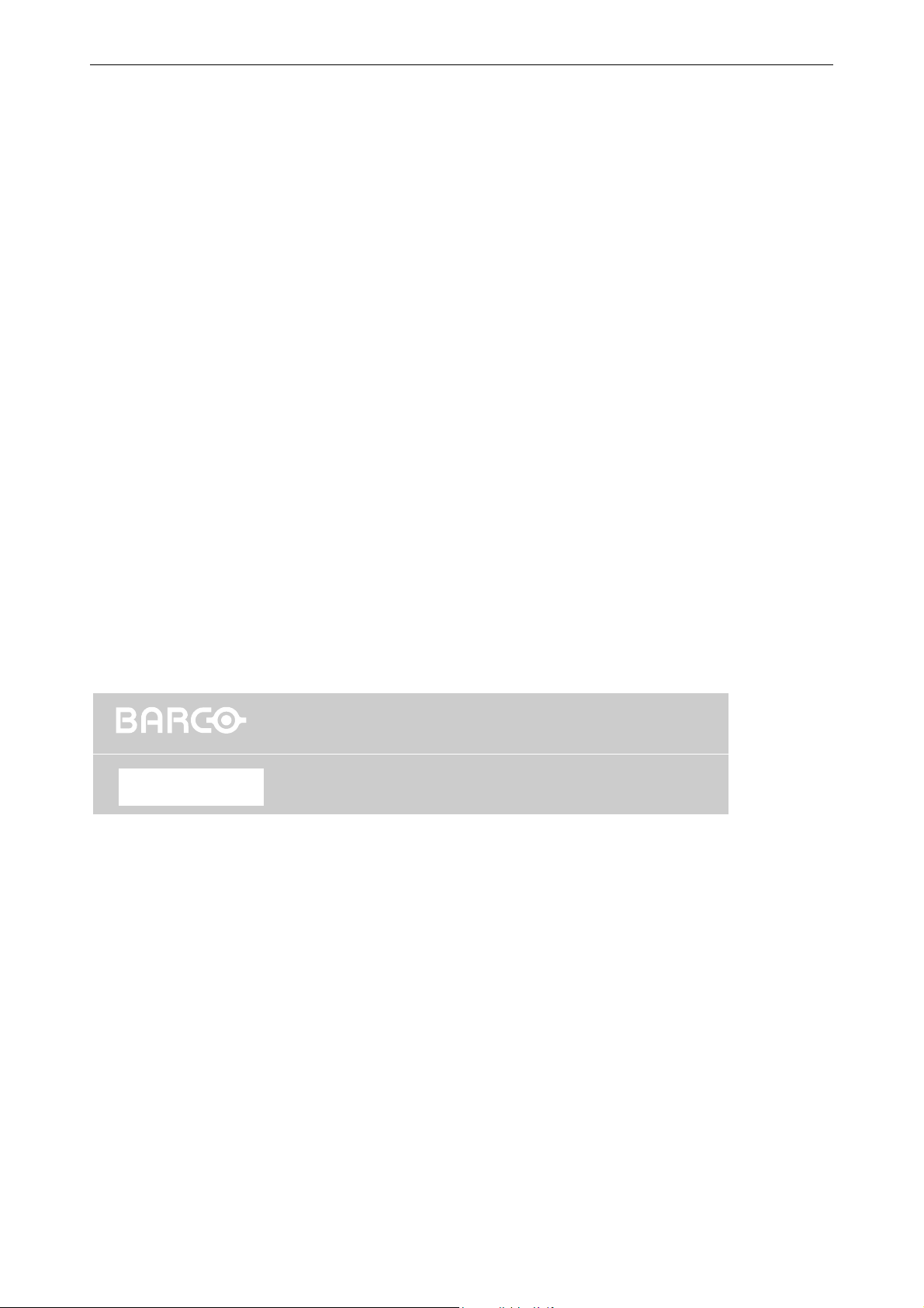
6.3 Activating the menu bar
Press the ADJ key on the RCU to display the menu bar.
OverView DG
Operation
Use the cursor key on the RCU to select a menu. Press Enter to activate it.
BrightnessStatusLamps
Figure 6-1
menu bar
Barco - OverView D series - Doc-3353-2 - user's manual - Revision 04 - April 2005
________________________________________________________________________
6-2
Page 40
6. Menu structure
6.4 Operation menu
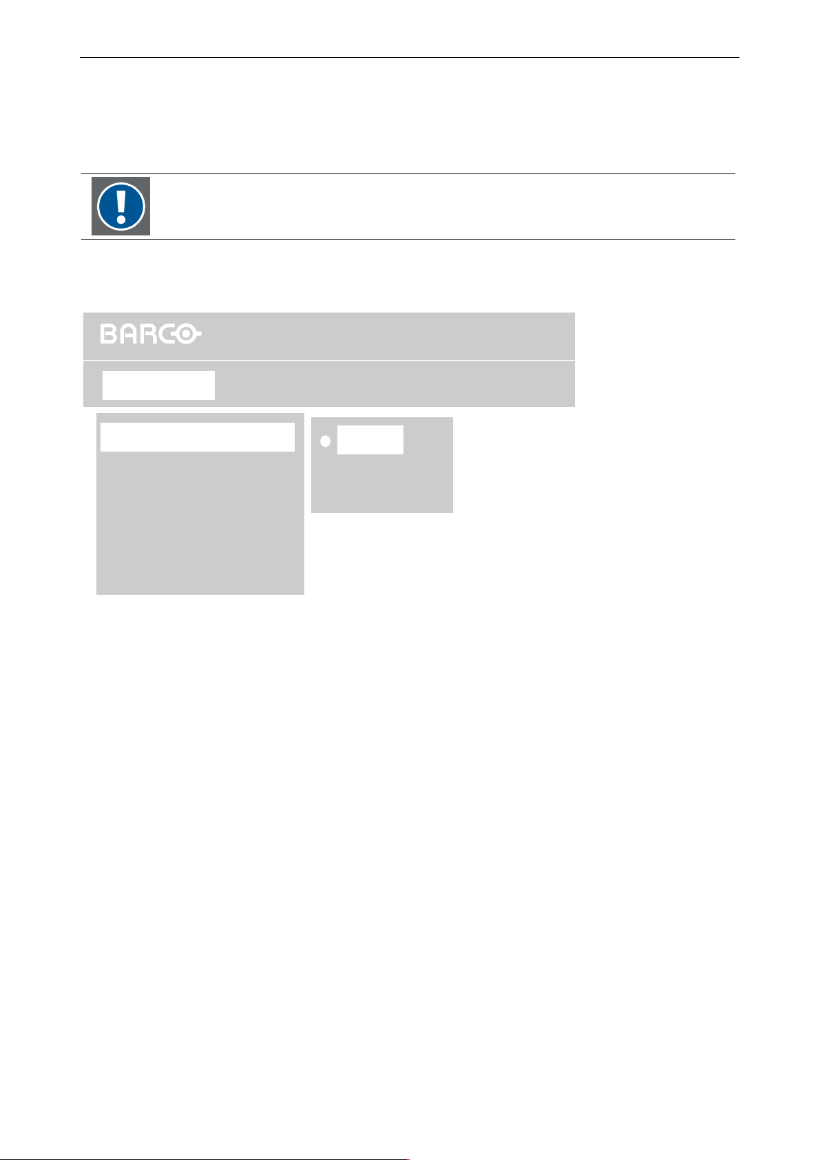
The Operation menu comprises the items Background, Message Box, Error Box, Startup screen, Language,
and – only in case of SXGA+ resolution – Source Selection.
Only projection modules with SXGA+ resolution feature Source Selection!
6.4.1 Background
OverView D
Operation
Background
Message Box
Error Box
Startup screen
Language
Source Selection
If there is no signal connected to the projector, the background will be a black or a blue screen or color bars,
depending on the background settings.
To select the background, proceed as follows:
• Use the cursor keys to highlight Background
• Press ENTER to select.
• The currently selected background is indicated with a white dot.
• Use the cursor keys to highlight the desired background
Blue
Black
Color Bars
BrightnessStatusLamps
Figure 6-2
Operation menu, Background
• Press Enter to select.
Barco - OverView D series - Doc-3353-2 - user's manual - Revision 04 - April 2005
________________________________________________________________________
6-3
Page 41
6.4.2 Message box
6. Menu structure
OverView D
Operation
Background
Message Box
Error Box
Startup screen
Disabled
Enabled
BrightnessStatusLamps
Language
Source Selection
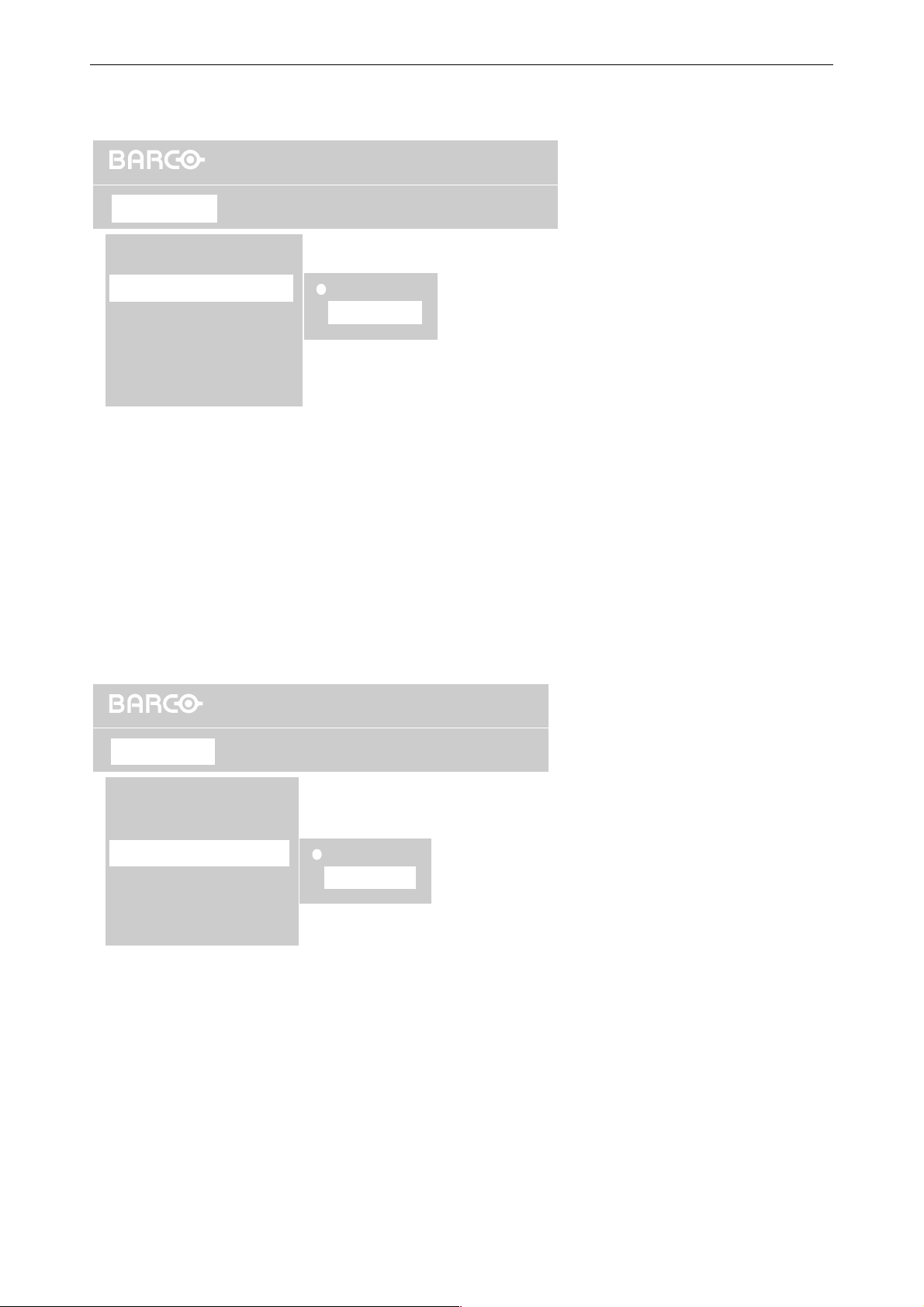
Message Boxes can be displayed (overlaying the application) or hidden.
• Use the cursor keys to highlight Message Box
• Press ENTER to select.
• The currently selected status is indicated with a white dot.
• Push the cursor key up or down to highlight Disabled, or Enabled
• Press ENTER to select.
Operation menu, Message Box
Figure 6-3
6.4.3 Error box
OverView D
Operation
Background
Message Box
Error Box
Startup screen
Language
Source Selection
Error Boxes can be displayed (overlaying the application) or hidden.
• Use the cursor keys to highlight Error Box
• Press ENTER to select.
• The currently selected status is indicated with a white dot.
• Push the cursor key up or down to highlight Disabled, or Enabled
Disabled
Enabled
BrightnessStatusLamps
Operation menu, Error box
Figure 6-4
• Press ENTER to select.
Barco - OverView D series - Doc-3353-2 - user's manual - Revision 04 - April 2005
________________________________________________________________________
6-4
Page 42
6.4.4 Startup Screen
6. Menu structure
OverView D
Operation
Background
Message Box
Error Box
Startup screen
Language
Source Selection
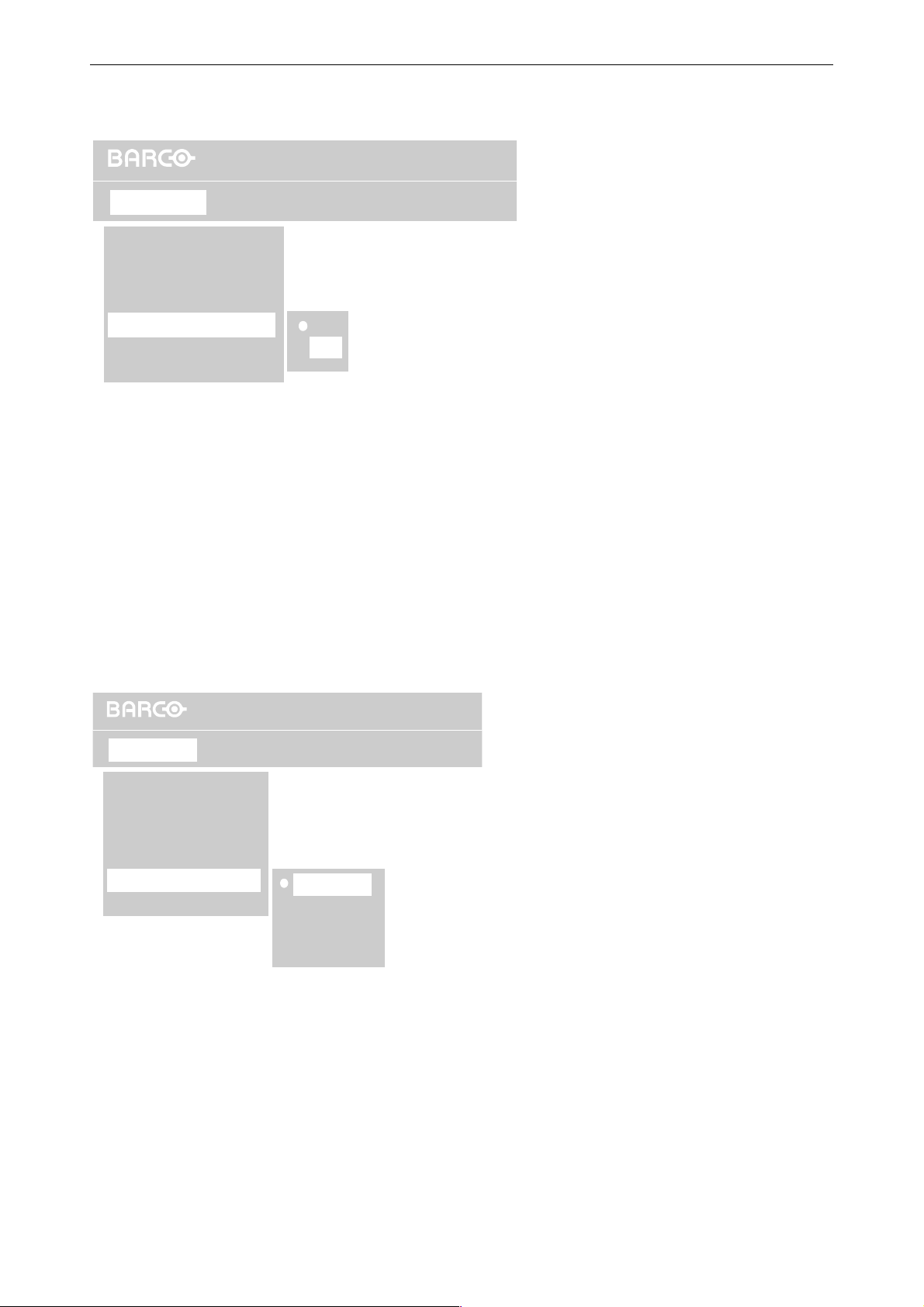
This command switches on or off the Startup screen. If switched on, the projector shows the identification information when starting up.
• Use the cursor keys to highlight Startup screen
• Press ENTER to select.
• The currently selected status is indicated with a white dot.
• Use the cursor keys to highlight the desired behavior
• Press Enter to select.
On
Off
BrightnessStatusLamps
Figure 6-5
Operation menu, Startup screen
6.4.5 Language
OverView D
Operation
Background
Message Box
Error Box
Startup screen
Language
Source Selection
The list of selectable languages for the menus is depending on the software of the projector. For OVERVIEW D,
currently English is the only language.
The active language is indicated with a white dot.
Languages which are not available are grayed out.
English
Francais
Deutsch
Espanol
BrightnessStatusLamps
Figure 6-6
Operation menu, Language
Barco - OverView D series - Doc-3353-2 - user's manual - Revision 04 - April 2005
________________________________________________________________________
6-5
Page 43
6. Menu structure
6.4.6 Source selection
This menu is only available with SXGA+ resolution!
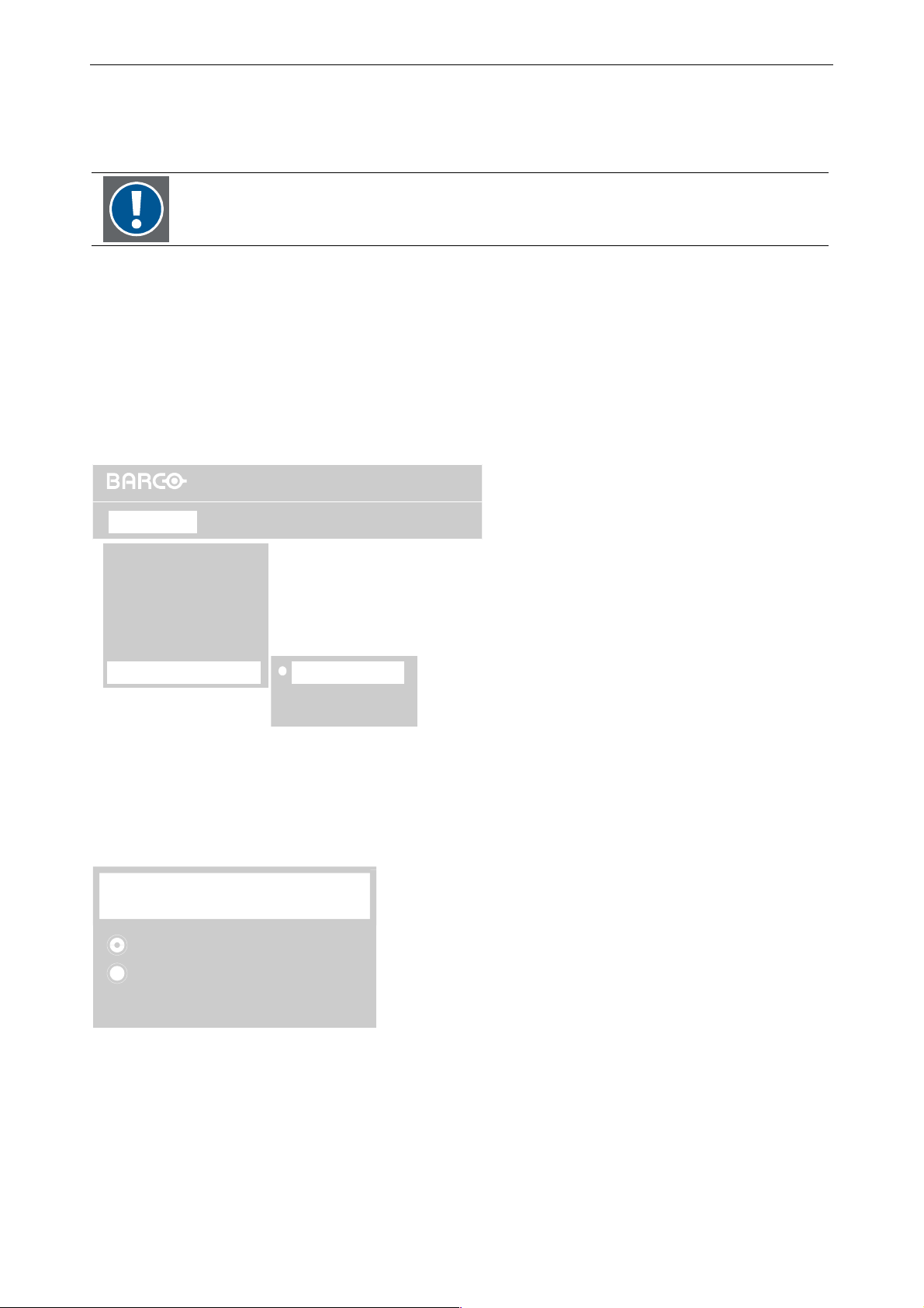
Projection units with SXGA+ resolution feature two DVI-D inputs, thus two sources can simultaneously be connected. The selection of the source to be displayed is done in the Source Selection menu. The following operating modes are available Manual, Auto, Auto Switch.
• Use the cursor keys to highlight Source Selection
• Press ENTER to select.
• The currently selected status is indicated with a white dot.
• Use the cursor keys to highlight the desired operating mode
• Press Enter to select.
OverView D
Operation
Background
Message Box
Error Box
Startup screen
Language
Source Selection
Manual...
BrightnessStatusLamps
Auto...
Auto Switch...
Operation menu,Source Selection
Manual
Selecting this command displays a dialog where the source to be displayed can be selected:
Manual Source Selection
Source 1
Figure 6-7
Source 2
Operation menu,Source Selection, Manual
Select the desired Source (Source 1 or Source 2). This source will be displayed. In case this source fails, the
background as selected in Operation | Background (color bar, blue, black) will be displayed, no matter if there is
a signal applied to Source 2 or not. The status of Source 2 has no impact on the behavior.
In this operating mode, the behavior is the same as with one DVI-D input only, except that there is the possibility
to connect two sources and select alternatively one them without the need of re-cabling.
Barco - OverView D series - Doc-3353-2 - user's manual - Revision 04 - April 2005
________________________________________________________________________
Figure 6-8
6-6
Page 44
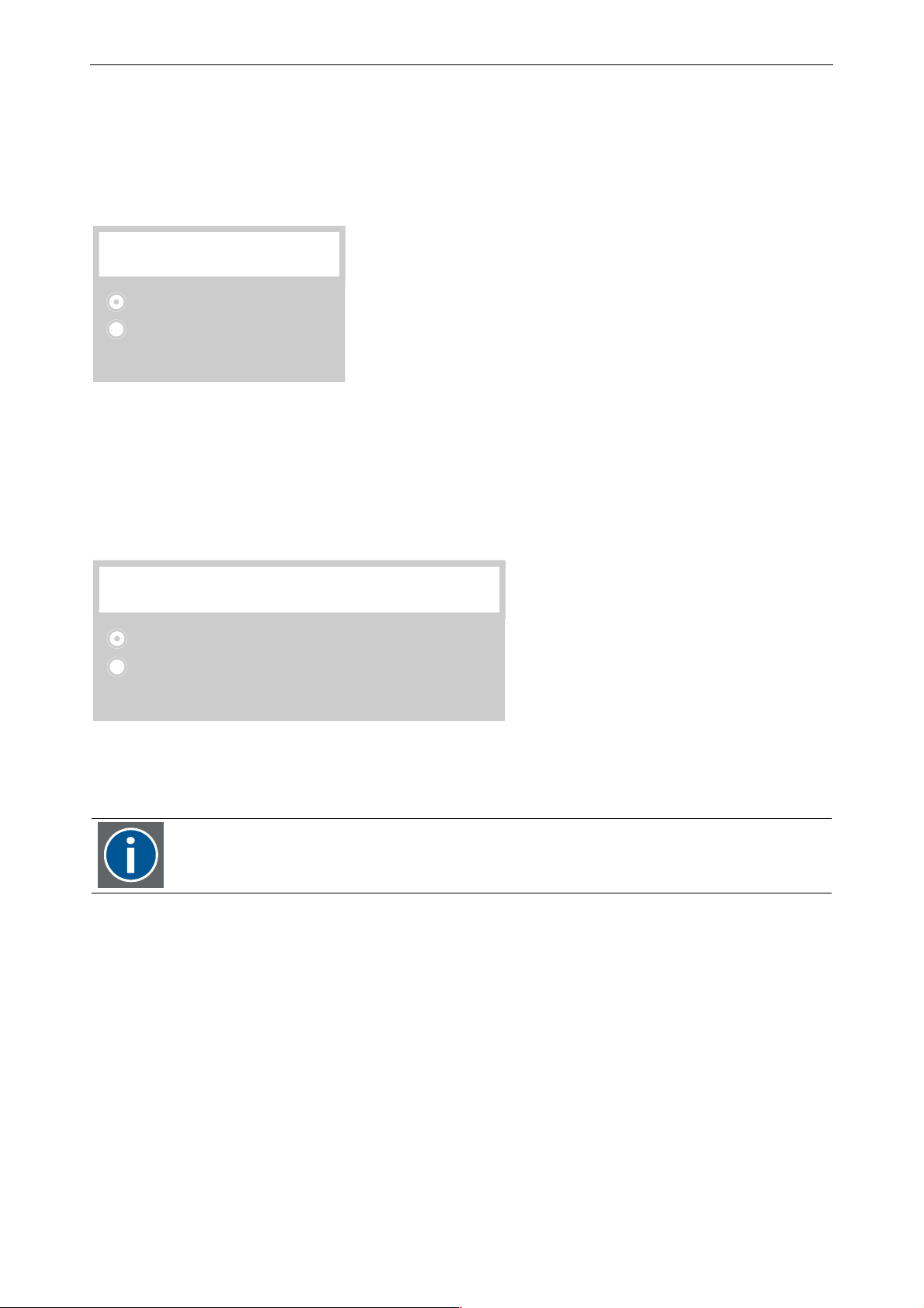
6. Menu structure
Auto
Selecting this command displays a dialog where the source to be displayed can be selected. This source will always have highest priority and be displayed whenever possible. In case the signal fails, the system automatically
switches to the other source. As soon as the originally selected source is live again, the system switches back to
it! Only in case neither source 1 nor source 2 are present, the background as selected in Operation | Background
(color bar, blue, black) will be displayed.
Auto Source Selection
Source 1
Source 2
:
Operation menu,Source Selection, Auto
Auto Switch
Selecting this command displays a dialog where the source to be displayed can be selected. As long as this
source is present, it also has priority. As soon the selected source is no longer available, the system switches to
the other source and also assigns priority to this source: Even if the originally displayed source will be present
again, it will not be switched to unless the other source fails.
Figure 6-9
Auto Switch Toggle - Source Selection
Source 1
Source 2
Operation menu,Source Selection, Auto Switch
Source Selection: summary
In Manual mode and in Auto mode source selection will remain unless explicitely changed.
In Auto Switch mode source selection will remain as long as the selected source is present,
then automatically toggle to the other source.
The following tables lists all possible cases for connecting source 1 and source 2 as well as the behavior in each
of the operation modes: Manual, Auto, Auto Switch.
Figure 6-10
Barco - OverView D series - Doc-3353-2 - user's manual - Revision 04 - April 2005
________________________________________________________________________
6-7
Page 45
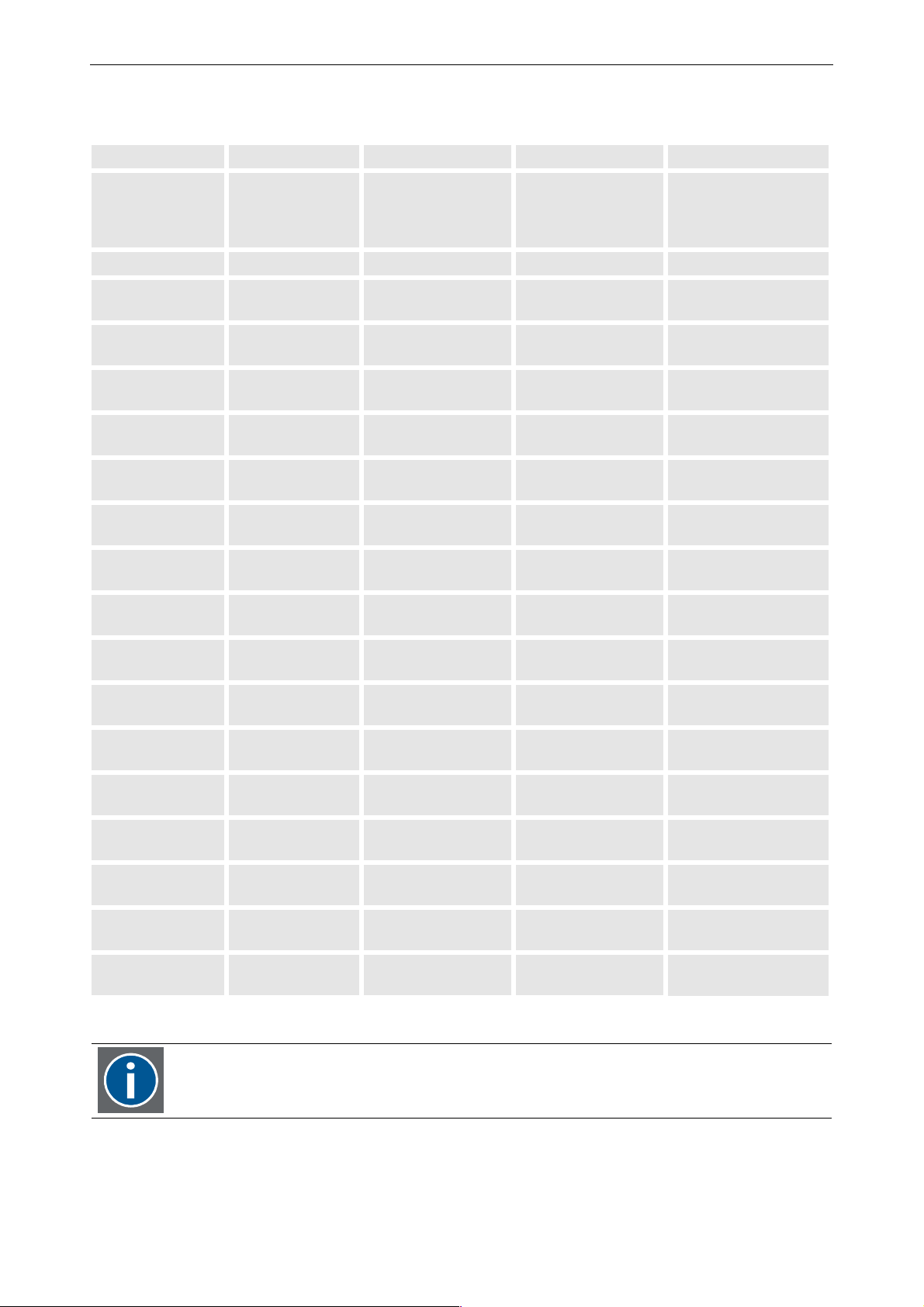
6. Menu structure
Starting point: in all three operation modes source 1 is selected.
Source 1 / DVI 1 Source 2 / DVI 2 Manual mode Auto mode Auto Switch mode
Selected source:
will remain source 1
during all combinations!
Selected source:
will remain source 1
during all combinations!
Selected source (priority):
will toggle between
source 1 and source 2
source 1 source 1 source 1 <--> source 2
not connected not connected background background background,
priority = source 1
not connected gets connected background switch to source 2
switch to source 2,
priority = source 2
not connected present background display source 2 display source 2,
priority = source 2
not connected gets disconnected background switch to background switch to background,
priority = source 2
gets connected not connected switch to source1 switch to source 1
switch to source 1,
priority = source 1
gets connected gets connected switch to source1 switch to source1 switch to source 1,
priority = source 1
gets connected present switch to source1 switch to source1 display source 2,
priority = source 2
gets connected gets disconnected switch to source1 switch to source1
switch to source 1,
priority = source 1
present not connected display source 1 display source 1 display source 1,
priority = source 1
present gets connected display source 1 display source 1 display source 1,
priority = source 1
present present display source 1 display source 1
display source 1,
priority = source 1
present gets disconnected display source 1 display source 1 display source 1,
priority = source 1
gets disconnected not connected switch to background switch to background switch to background,
priority = source 1
gets disconnected gets connected switch to background switch to source 2
switch to source 2,
priority = source 2
gets disconnected present switch to background display source 2 display source 2,
priority = source 2
gets disconnected gets disconnected switch to background switch to background switch to background,
priority = source1
In Auto Switch mode, as soon as the source is switched, priority is also switched!
Barco - OverView D series - Doc-3353-2 - user's manual - Revision 04 - April 2005
________________________________________________________________________
6-8
Page 46
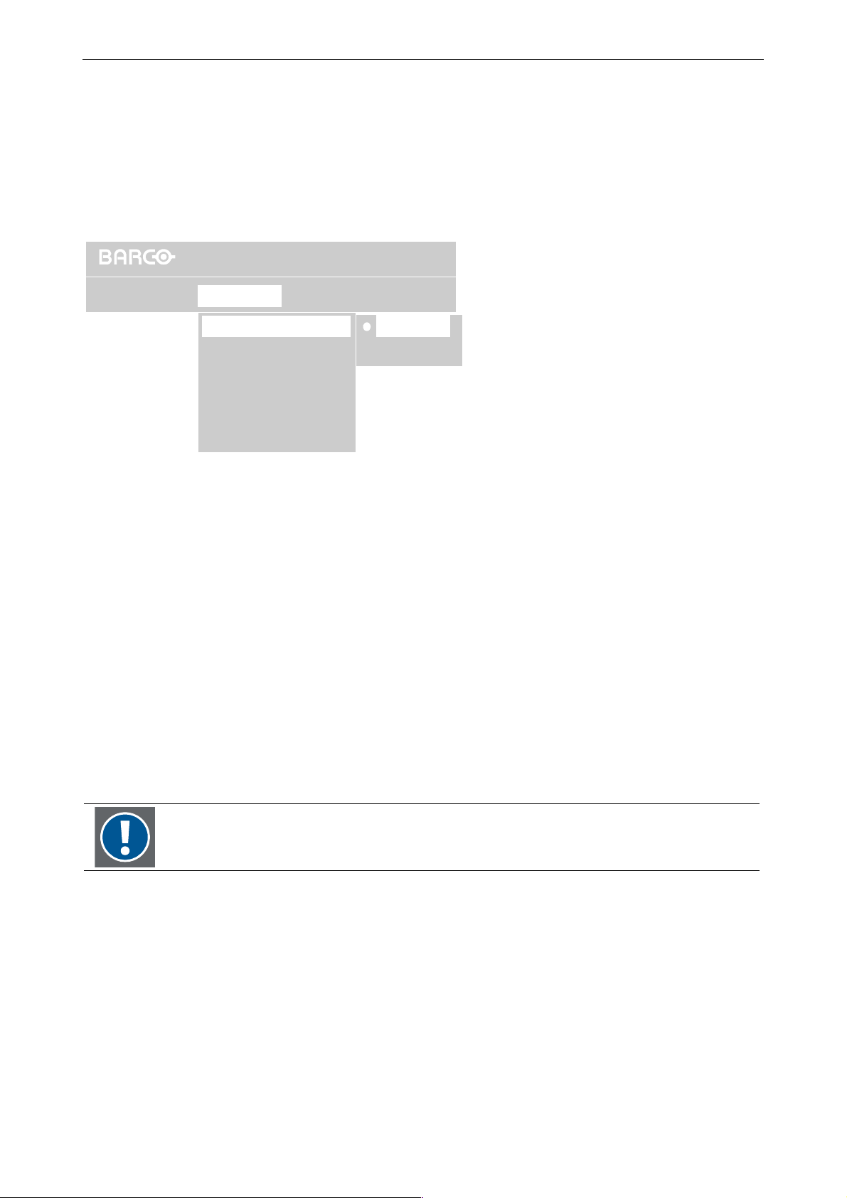
6. Menu structure
6.5 Lamps menu
Use the Lamps menu to select the active lamp, an operation mode, to optimize the lamp adjustment, and to see
and modify runtimes.
6.5.1 Active lamp
OVERVIEW D has a dual lamp system for 100% availability of the projector. The mode of operation can be selected
via the command Mode of the Lamps menu:
OverView DG
BrightnessStatus
Top
Bottom
Operation
Lamps
Active Lamp
Mode
History...
Lamp Optmizaton...
Runtimes...
Reset runtime
The active lamp is the one illuminating the DMD. The currently selected active lamp is indicated with a white dot.
Proceed as follows to change the active lamp
• Use the cursor key to highlight Active Lamp.
• Press Enter to select.
• Use the cursor key to highlight the desired active lamp
• Press Enter to select.
Depending on the operation mode of the projector, changing the active lamp initiate different actions:
Cold Standby or Auto Switch mode
Figure 6-11
Lamps menu, Mode
In this operation mode, the active lamp is on, the second lamp is switched off. Therefore when changing the
active lamp, the second lamp first has to be switched on (and the other lamp is switched off). Since a lamp requires some time to burn stable, the displayed image will first have reduced brightness. After some instants the
image will show the former brightness.
In these operation modes, a subsequent change of the active lamp is only possible after the
cool down cycle of the first lamp (about 30sec).
Hot Standby mode
In this operation mode, both lamps are switched on. Therefore when changing the active lamp, there is no noticeable impact on the displayed image (both lamp are adjusted to have the same brightness).
Since both lamps are one, a second subsequent change of the active lamp is immediately possible.
Barco - OverView D series - Doc-3353-2 - user's manual - Revision 04 - April 2005
________________________________________________________________________
6-9
Page 47
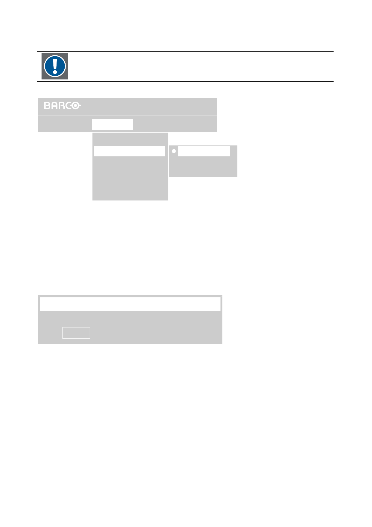
6.5.2 Mode
6. Menu structure
Hot Standby can only be selected if it has been enabled by a Barco technician (special
request).
If Hot Standby is disabled, this mode is grayed out.
OverView DG
BrightnessStatus
Hot Standby
Cold Standby
Auto Switch ...
Operation
Lamps
Active Lamp
Mode
History...
Lamp Optimization...
Runtimes...
Reset runtime
Proceed as follows to select the operation mode
• Use the cursor key to highlight Mode.
• Press Enter to select.
• The currently selected operation mode is indicated by white dot.
• Use the cursor key to highlight the desired operation mode
• Press Enter to select.
A message box is displayed to confirm the selection:
Lamp mode
Figure 6-12
Lamps menu, Mode
Are you sure to switch to ‘Cold Standby’ mode?
Yes No
Lamps menu, message box to confirm the selection
In Hot Standby both lamps are on. In case of a lamp failure, the light output of the other lamp is immediately
switched to illuminate the optics, and there is almost no noticeable effect on the displayed information: no loss
of information, no impact on quality. Switching time is about one second.
In Cold Standby mode the second lamp is only switched on in case a failure occurs with the active lamp. Since
the second lamp needs about one minute to reach a stable operating temperature, at the beginning the display
will have reduced brightness. The contents of information, however, is available nearly without interrupt.
Auto Switch mode is a special version of the ´Cold Standby mode: the lamps are active in turns. Since the lamp
is switched on some minutes in advance, the takeover of the other lamp is equally percepted as in Hot Standby
mode: no noticeable effect on the displayed information, no loss of information, no impact on quality.
The lamp activation time can be selected between 12 hours and 500 hours. Therefore when selecting Auto
Switch, a dialog pops up to enter the auto switch cycle time:
Barco - OverView D series - Doc-3353-2 - user's manual - Revision 04 - April 2005
_______________________________________________________________________
Figure 6-13
6-10
Page 48
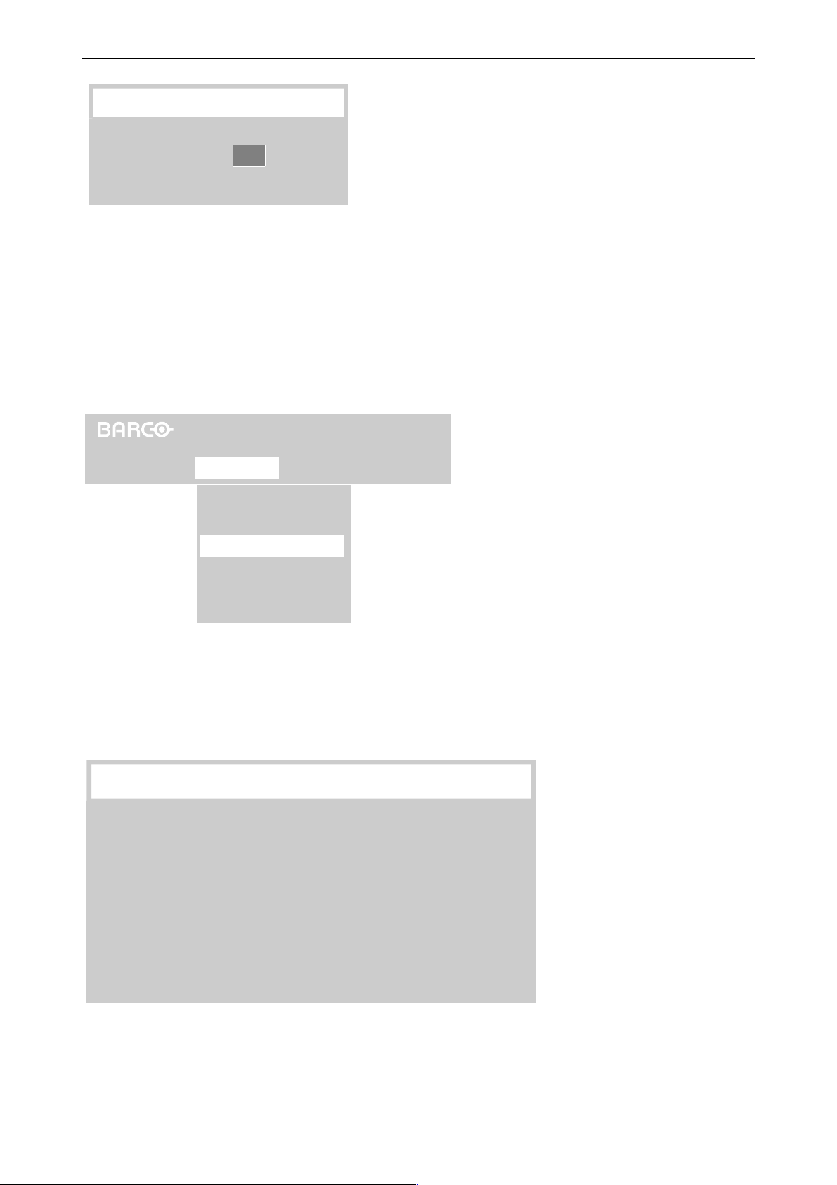
Auto Lamp Switch hours
6. Menu structure
Hours (12 to 500)
.
Proceed as follows to set the switching time:
• Use the cursor key to highlight the input field
• Use the numeric keys on the IR Remote-Control to enter the desired hours
• Press Enter to select.
24
Lamps menu, defining auto switch cycle time
6.5.3 History
Use this command to see the list of serial numbers and the current runtime of the lamps
OverView DG
Operation
Lamps
Active Lamp
Mode
History...
Lamp Optimization...
Runtimes...
Reset runtime
BrightnessStatus
Figure 6-14
Figure 6-15
Lamps menu, History
Proceed as follows to view the lamp history:
• Use the cursor key to highlight History
• Press Enter to select.
A dialog is displayed which shows the serial numbers and runtimes of the employed lamps.
Lamp history
Lamp Serial no. Runtime
Current lamps
Lamp Top 348
Lamp Bottom 279
dialog showing the history of the lamps of the projector
Figure 6-16
Barco - OverView D series - Doc-3353-2 - user's manual - Revision 04 - April 2005
_______________________________________________________________________
6-11
Page 49

6. Menu structure
6.5.4 Lamp optimization
Since the light is coupled into the light rod by means of a mirror, the position of the mirror together with the
actual lamp properties determine the light yield.
During the Lamp Optimization procedure, the light output of the active lamp in dependance of the tilting angle
of the mirror is measured, and the optimized mirror position for the lamp is determined.
The procedure should be performed subsequently for both lamps. The optimised positions are stored independently for both lamps, so that after setting the lamp lift in motion and thus changing the active lamp, the mirror
position is adjusted accordingly.
OverView DG
Operation
Lamps
Active Lamp
Mode
Status
Brightness
History...
Lamp Optimization...
Runtimes...
Reset runtime
This procedure optimizes the coupling of the active lamp into the optical system of the
projector and is immediately triggered by selecting the command Lamp Optimization.
During this procedure, the display gets dark for about 30seconds.
• Use the cursor keys to highlight Lamp Optimization
• Press ENTER to select.
The following message box is displayed:
Lamp Optimization
Lamp Optimization for top lamp in progress.
Please Wait.
Lamps menu, Lamp optimization
Figure 6-17
Lamp optimization in progress
The results of the optimization adjustments are saved individually for both lamps. Therefore after changing the
active lamp, no optimization procedure is required, the lamp will automatically be brought into the former determined best position.
However, when replacing the lamp, it is recommended to select Lamp Optimization, since the
new lamp has different parameters and therefore has to be adjusted anew.
Barco - OverView D series - Doc-3353-2 - user's manual - Revision 04 - April 2005
_______________________________________________________________________
Figure 6-18
6-12
Page 50
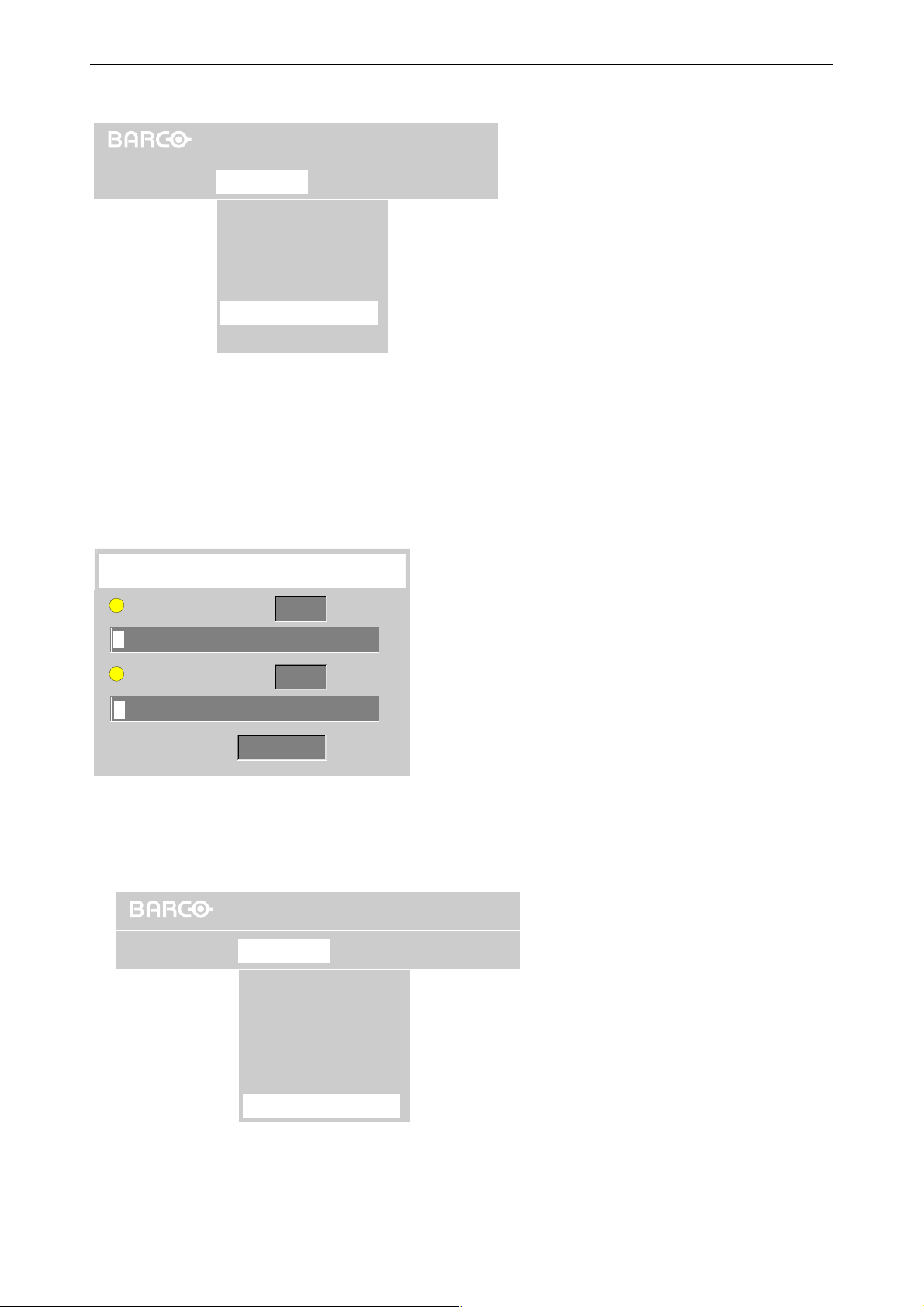
6.5.5 Runtimes
6. Menu structure
OverView DG
Operation
Lamps Brightness
Active Lamp
Mode
Status
History...
Lamp Optimization...
Runtimes...
Reset runtime
The Runtimes command displays a dialog where the runtimes of the lamps and the projector can be viewed.
To check the runtimes, proceed as follows:
• Use the cursor key to highlight Runtimes.
• Press Enter to select.
The Runtime dialog is displayed where the runtimes for both lamps and the projector itself are listed:
Figure 6-19
Lamps menu, Runtimes
Runtime
Lamp Top
125
hrs
Lamp Bottom
Projector
6.5.6 Reset runtime
Operation
159
380
hrs
hrs
OverView DG
Lamps
Active Lamp
Mode
History...
Lamp Optimization...
Runtimes...
Reset runtime
Status
Figure 6-20
dialog box Runtime
Brightness
Barco - OverView D series - Doc-3353-2 - user's manual - Revision 04 - April 2005
Figure 6-21
Reset runtime
_______________________________________________________________________
6-13
Page 51
After replacement of the lamp, the serial number of the new lamp has to be entered.
The command Reset runtime displays the dialog to enter the serial number.
To enter the serial number of the new lamp, proceed as follows:
• Use the cursor key to highlight Reset runtime.
• Press Enter to select.
The following dialog is displayed:
Reset lamp runtime
Enter serial number of new lamp
6. Menu structure
Lamp 1
Accept
000000
Cancel
dialog to enter the serial number of a new lamp
• Use the cursor keys to highlight the input field.
• Use the numeric keys on the RCU to enter the serial number of the new lamp.
• Click Accept to activate the serial number.
Figure 6-22
Barco - OverView D series - Doc-3353-2 - user's manual - Revision 04 - April 2005
_______________________________________________________________________
6-14
Page 52
6. Menu structure
6.6 Status Menu
This menu allows checking and controlling the projector identification parameters as well as setting some operation features.
6.6.1 Identification
OverView DG
Operation
Lamps Brightness
Status
Identification
Over Temp Protection
Automatic startup
Standby timer..
Installation
Status menu, Identification
To view the projector identification, proceed as follows:
• Use the cursor key to highlight Identification.
• Press Enter to select.
A submenu with the entries Short and Long is opened
Use the cursor key to highlight the desired status information.
Press Enter to select.
If Short is selected, the following dialog is displayed which shows type, address, software version, baudrate,
orientation, and the serial numbers of the projector:
Figure 6-23
Identification
Type OverView DG
Address 1
Software 00.31
RS232 baudrate 9600
Orientation Front / Ceiling
Serial Number IU 5107951
Serial Number PU 5107998
projector identification short: dialog box showing the projector properties
This dialog is also shown during starting up the projector if operation|startup screen is
enabled.
Barco - OverView D series - Doc-3353-2 - user's manual - Revision 04 - April 2005
Figure 6-24
_______________________________________________________________________
6-15
Page 53
6. Menu structure
If Long is selected, a list of parameter is shown. This list shows important information for the Barco service technician.
Parameter
17511
22512
3 5998 13
4014
5015
616
717
818
919
10 20
projector identification long: dialog box showing service information
Figure 6-25
6.6.2 Error
OverView DG
Operation
Selecting the Error menu entry displays a sub menu which shows the status of the projector properties. The sub
menu includes the following entries:
Error
Lamps BrightnessStatus
Identification
Error...
Over Temp Protection...
Automatic startup
Standby timer..
Figure 6-26
Status menu: Error
Lamp Top
Lamp Bottom
Fan
Over Temperature
Under Voltage
Illumination Unit read
Brightness
Lift
Reference search
Lamp door
Figure 6-27
Error sub menu
The properties are checked regularly. In case of a critical status (e.g. lamp door is open, which means that the
cooling cycle cannot operate properly), the checkbox is ticked. If the critical status is solved when checking status
next time, the checkbox is cleared.
Barco - OverView D series - Doc-3353-2 - user's manual - Revision 04 - April 2005
_______________________________________________________________________
6-16
Page 54
6. Menu structure
Lamp top / Lamp bottom
A lamp error occurs if the active lamp fails during operation and if the ignition of the inactive lamp fails, respectively.
The lamp error bit is set, and the lamp lift can no longer be moved!
This error has to be reset manually.
Press the On/Res. switch for about 6 sec. on the rear of the system to reset the error.
Reset the error
• once without doing anything else to make sure that the lamp is really broken
• after a lamp exchange
Depending on the operation mode, the behavior of the system differs.
In Hot Standby mode, after resetting the error, the lamp is ignited. If ignition is successful and the lamp has
been switched on, the lift can be moved again. If ignition is a failure, the lamp error is set again and the lift remains locked.
In Cold Standby mode, since the replaced lamp is the inactive lamp, after resetting the error, there is no lamp
check, and the lamp remains switched off. The lift can be moved again. If then the system changes the active
lamp by means of the lift, the new lamp is tried to be lighted. If it is a flop, the error bit is set again, and within
about 5 seconds, the projector switches back to the lamp which has been the active one. Then the lift is locked
again.
In Cold Standby, after switching the active lamp, the lamp which has been active at that
time is only switched off if the second lamp succeeds in being switched on.
Fan
OverView D series employs two fans: one which is located behind the filter pad frame and connected to the illumination unit and the projection unit, and one which is located beneath the bottom lamp.
Both fans are mandatory for operating OverView D, and in case one of them is out of order, it need to be replaced immediately!
The status of both fans together can be derived from the fan LED. (The fan LED is the bottom LED of the three
status LEDs).
Fan LED green: both fans work
Fan LED is red (static): fans are off!
Fan LED is blinking red: a fan error has occurred. At least one fan is not running
The fan error is an auto-updated error. It’s of no use to reset the error manually since the fan is
monitored continuously. In case the error is solved, error bit is reset automatically. In case the
error persists, the error bit is set (again).
In case the error is not reset automatically, call Barco support.
Barco - OverView D series - Doc-3353-2 - user's manual - Revision 04 - April 2005
_______________________________________________________________________
6-17
Page 55
6. Menu structure
Over temperature
A sensor which is located behind the tilt mirror in the illumination unit checks the temperature. In case a critical
temperature (40°C) is reached, the over temperature bit is set, the shut down cycle counter starts its countdown,
and the projector is shut down within five minutes to prevent the system from severe damage.
If desired, the countdown counter can be disabled and thus over temperature protection..
It is highly recommended NOT to switch of over temperature protection.
In case the temperature drops within the countdown period below the critical limit, the countdown counter
stops, and the over temperature bit is reset automatically.
Under Voltage Error
This error occurs if the voltage of the power factor correction board is below a critical limit.
If DMD parking is enabled, the DMD will be parked after 10ms.
If the error is resolved during this time (practical not possible), the DMD parking will not be done.
Illumination unit read
This error occurs if there is no I²C communication between the illumination unit and the projection unit.
This error usually occurs when starting up the projector.
If this error bit is set, the dimmer motor and the motor of the mirrors in the illumination unit are not running.
• Switch off the projector, check the power cable and switch it on again.
It is not recommended to manually reset of the error, since this only affects the error bit,
but not the error itself.
Brightness
Brightness is checked regularly with respect to the target. If the achieved brightness is too high or too low, the
brightness checkbox is ticked.
Manual reset of this error makes no sense.
Lift error
This error occurs if the lift did not reach the switches at its upper and lower end position, respectively.
Manual reset of this error makes no sense.
To solve the problem, call Barco Support!
Barco - OverView D series - Doc-3353-2 - user's manual - Revision 04 - April 2005
_______________________________________________________________________
6-18
Page 56
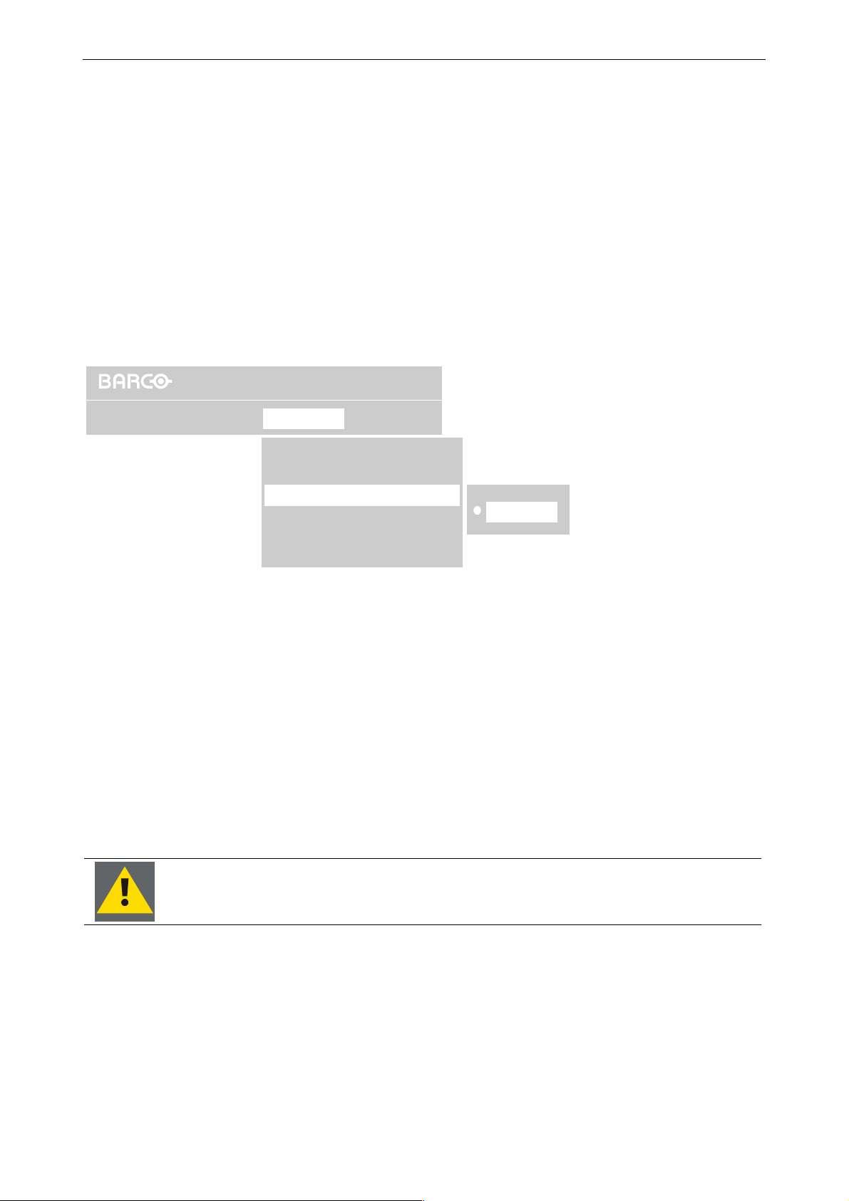
6. Menu structure
A
Reference Search
This error occurs if the mechanical dimmer cannot find its home position.
Firmware release 2.0 provides a new algorithm which ensures that there is at least some light on the screen.
With Firmware release 1.x the screen remains dark.
Switch off the projector and switch it on again. If the error still remains, call Barco Support!
Lamp door
This error occurs if a lamp door is opened. When the error bit is set, a counter starts, and if the door is not closed
within the counter cycle of 15minutes, the projector will shut down. If the door is closed within this counter period, the error bit and the counter will be reset, and the projector performs a lamp lift readjustment after closing
the door. This is required since the lamp lift could be at a shifted position.
6.6.3 Over temp protection
OverView DG
Operation Lamps BrightnessStatus
Identification
Error...
Over Temp Protection...
utomatic startup
Disabled
Enabled
Standby timer..
Status menu: Over Temp Protection
To view or to switch on/off the Over Temp protection, proceed as follows:
• Use the cursor key to highlight Over temp Protection.
• Press Enter to select.
The currently selected status is indicated by white dot.
Use the cursor key to highlight the desired status.
Press Enter to select.
This command refers to the internal temperature sensor. Per default, Over Temp Protection is enabled. In case a
critical temperature is reached, the projector is shut down within five minutes to prevent the system from severe
damage. An Error Message is displayed.
If desired, the customer can disable this behavior. However he should be aware that the device can be damaged!
Figure 6-28
It is highly recommended NOT to switch of Over Temp Protection.
Barco - OverView D series - Doc-3353-2 - user's manual - Revision 04 - April 2005
_______________________________________________________________________
6-19
Page 57
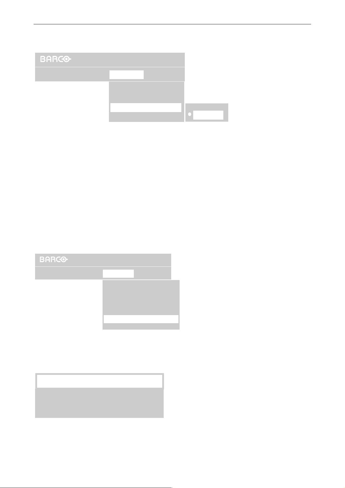
6.6.4 Automatic startup
6. Menu structure
OverView DG
Operation
To view or switch on/off the Automatic startup, proceed as follows:
• Use the cursor key to highlight Automatic startup.
• Press Enter to select.
The currently selected status is indicated by white dot.
Use the cursor key to highlight the desired status.
Press Enter to select.
If Automatic startup is ON, the projector will immediately be started after being connected to the mains (power
switch switched on).
If Automatic startup is OFF, the projector will go in Standby mode after being connected to the mains (power
switch switched on).
Lamps BrightnessStatus
Identification
Over Temp Protection
Automatic startup
Standby timer..
On
Off
Figure 6-29
Status menu, Automatic startup
6.6.5 Standby timer
Installation
OverView DG
Operation
If there is no signal, and the standby timer is enabled, a dialog box is displayed and the projector will shut down
after a determined time (power save).
Message
No signal available.
The projector will go to Standby in 300 sec.
Lamps Brightness
Status
Identification
Identification
Error...
Error...
Over Temp Protection...
Over Temp Protection...
Automatic startup
Automatic startup
Standby timer..
Standby timer..
Status menu, Standby timer
Figure 6-30
Barco - OverView D series - Doc-3353-2 - user's manual - Revision 04 - April 2005
dialog box warning about the projector switching to standby
_______________________________________________________________________
Figure 6-31
6-20
Page 58
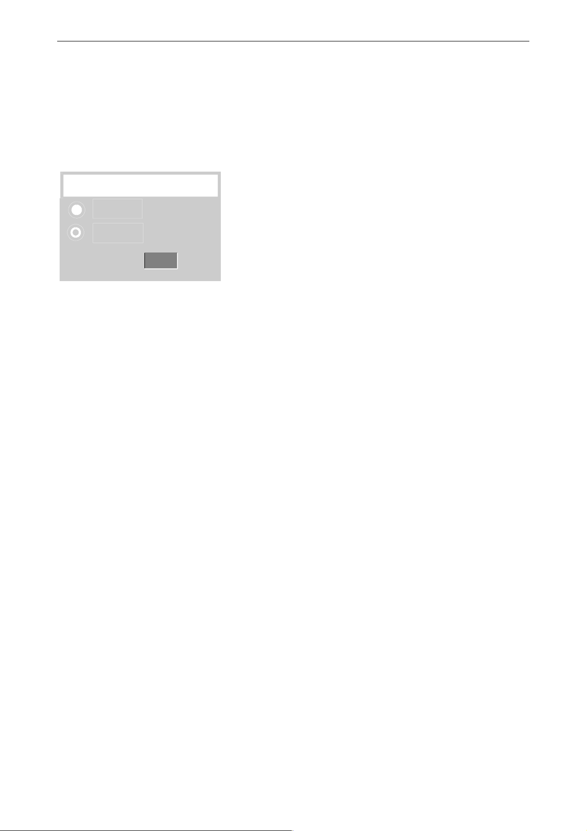
6. Menu structure
The countdown time can be set in a dialog box in a range from 180 to 3600 seconds (default value = 300). The
Timer can also be disabled.
To enable the timer and to set the countdown time proceed as follows:
• User the cursor key to highlight Standby timer.
• Press Enter to select
A dialog box is displayed:
Standby timer
Enabled
Disabled
Countdown to
sec
0
The current status is indicated by a selected radio button.
To select the other status, proceed as follows:
• Use the cursor key to highlight the desired status.
• Press Enter to select.
To change the countdown time, proceed as follows:
• Use the cursor keys to browse to the input field
• Enter the desired value by means of the numeric keys on the RCU.
• Press Enter to activate
dialog box to control the Standby timer
Figure 6-32
Barco - OverView D series - Doc-3353-2 - user's manual - Revision 04 - April 2005
_______________________________________________________________________
6-21
Page 59
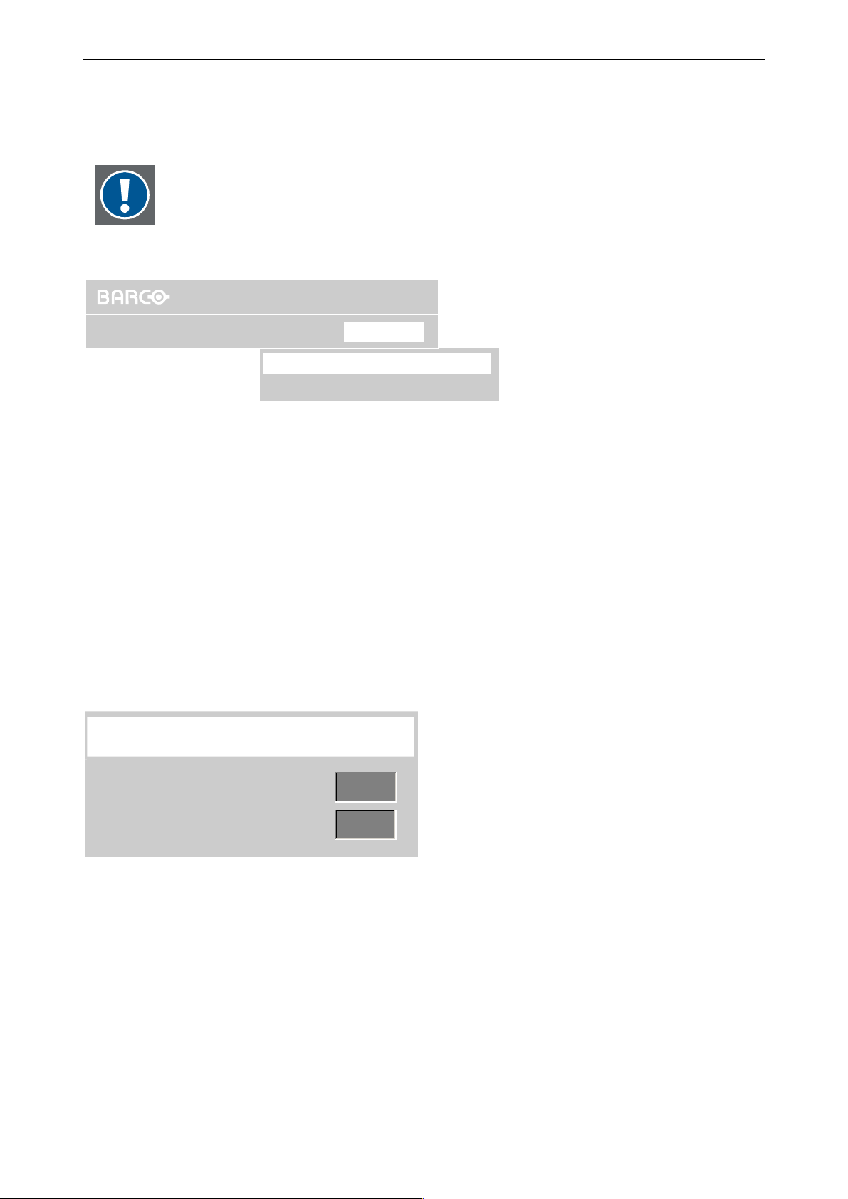
6.7 Brightness menu
This menu refers to the optical dimmer and can be enabled or disabled.
If grayed out, it has to be enabled by a Barco service technician.
6.7.1 Set brightness
OverView DG
6. Menu structure
Operation
Display Walls consisting of OVERVIEW D projection modules are adjusted to homogeneous brightness. Therefore all
projectors are individually adjusted to feature this common brightness.
This individual projector adjustment is done after set up of the Display Wall by the Barco Support Technicians. On
the screen, the brightness is measured by means of a lux meter, and the sensor of the optical dimmer (DIS) is
calibrated based on this measurement.
The user can adjust the brightness between 100% and 50% by means of the optical dimmer. This adjustment can
be performed via the command Brightness|Set Brightness.
To adjust the brightness, proceed as follows:
• Use the cursor key to highlight Set Brightness
• Press Enter to select.
The following dialog is displayed to modify the target value:
Lamps Status
Set Brightness..
Brightness Correction (%) Top
Brightness
Figure 6-33
Brightness menu, Set Brightness
Set Brightness
Valu e
Valu e
DIS Value
DIS Value
To edit the target value, proceed as follows:
• Use the cursor key to activate the input field.
• Use the numeric keys on the RCU to enter a new target value.
The related DIS value is indicated.
Barco - OverView D series - Doc-3353-2 - user's manual - Revision 04 - April 2005
280
280
277
277
dialog to modify the brightness target value
Figure 6-34
_______________________________________________________________________
6-22
Page 60
6. Menu structure
As mentioned before, the optical dimmer can modify the brightness between 100% and 50%. It is obvious that
the target value cannot exceed the max. possible value (100%) or be lower than the min. possible value (50%).
In case the user enters a value beyond the max. target value, or a value below the 50% limit, the following
message pops up:
Message
Desired Brightness not achieved
Warning: the user target value is beyond the range of the dimmer
Figure 6-35
Please note: this message does not indicate a dimmer failure!
This message indicates that the dimmer cannot achieve the desired value but operates at
his limits (100%, or 50% respectively).
6.7.2 Brightness correction (%)
OverView DG
Operation
Lamps Status
Set Brightness..
Brightness Correction (%) Top
Display walls consisting of OVERVIEW D projection modules are adjusted to homogeneous brightness. All projectors
are individually adjusted to feature this common brightness.
This individual projector adjustment is done after set up of the Display Wall by the Barco Support Technicians. On
the screen, the brightness is measured by means of a lux meter, and the sensor of the optical dimmer (DIS) is
calibrated based on this measurement.
This calibration is done for both lamps.
Brightness
Figure 6-36
Brightness menu, Brightness correction
If in spite of this adjustment the user considers the projection module too dark or too bright, he can modify this
brightness by correcting the DIS calibration value by
± 30%.
This correction can be done via the command Brightness|Brightness Correction (%). This menu entry refers to
the currently active lamp which is automatically indicated in the menu entry.
To modify the brightness of a projection module, proceed as follows:
• Use the cursor key to highlight Brightness Correction (%) Top/Bottom
• Press Enter to select.
The following dialog is displayed to modify the correction value. The actual correction values and the DIS value
are indicated.
Brightness Correction (%)-Top
+0,0
DIS Value
Barco - OverView D series - Doc-3353-2 - user's manual - Revision 04 - April 2005
277
dialog to modify the correction value
Figure 6-37
_______________________________________________________________________
6-23
Page 61
To increase the percentage, proceed as follows:
• User the cursor key to activate the right white arrow
•
Click on the right white arrow until the desired percentage is reached.
To decrease the percentage, proceed as follows:
• User the cursor key to activate the left white arrow
•
Click on the left white arrow until the desired percentage is reached.
The indicated DIS value does not change but remains constant.
Modification of the correction value has impact on the calibration of the DIS sensor, not
on the absolute value which has to be the same for all projection modules of the Display
Wall.
Due to the change in calibration, the brightness is adjusted while the common (all
projection modules of the Display Wall) DIS value persists.
6. Menu structure
Barco - OverView D series - Doc-3353-2 - user's manual - Revision 04 - April 2005
_______________________________________________________________________
6-24
Page 62
7. Maintenance and servicing
7 Maintenance and servicing
OVERVIEW D requires very little maintenance and servicing. Maintenance operations are nevertheless necessary at
regular intervals to guarantee good operational performance.
This chapter describes maintenance and servicing of O
Only authorized personnel should carry out other maintenance work not explicitly
mentioned in this installation manual!
Never open the case of OverView D without first disconnecting the power supply cord!
Measurements and tests with the opened device may be carried out only in the factory
or by specially trained personnel, due to the dangers of electrical shock.
VERVIEW D.
Barco - OverView D series - Doc-3353-2 - user's manual - Revision 04 - April 2005
________________________________________________________________________
7-1
Page 63
7. Maintenance and servicing
7.1 Manual user interface
The manual user interface located at the rear of OVERVIEW D includes the switches of the illumination unit [1], [2],
[3], the LED’s of the illumination unit, and the LED’s of the lamp doors.
The manual user interface is intended to operate the projection module when servicing. The trained Barco support technicians can analyze errors by evaluating the status of the LEDs.
7.1.1 Power switch
The power switch [1] connects/disconnects the projector from the mains. Once switched on, the projector should
be disconnected from the mains only for servicing.
Do not press the power switch while the projector is running. The projector has to be
switched to Standby first!
7.1.2 Standby switch
The Standby Switch [2] has 3 positions: neutral (not pushed), up (pushed to the top), down (pushed to the bottom).
The switch is slope sensitive and reacts when changing from one position to the other. To prevent operation
errors, a minimum time is required for pushing. After sending a command (after pushing the switch), the next
command can only be sent after the release of the switch for at lease 0.5s.
In case the power switch [1] is off, there is no reaction.
Projector status Power LED Action Push
time
Up switching on the projectorStandby
Down only in combination with active lamp selection switch
Up 3sec reset of error after servicingStandby
Down no function
Up only in combination with active lamp selection switch
Down 3sec switching off the projector (standby)
Up 6sec reset of non critical errorOn
down 3sec
(no error)
(error)
On
(no error)
(error)
red, static
red,
blinking fast
green, static
green,
blinking slowly
Function
[3], for servicing only
[3]
switching off the projector (standby),
reset of non critical error
Projector is starting up or shutting
down
Barco - OverView D series - Doc-3353-2 - user's manual - Revision 04 - April 2005
blinking yellow
Up no function
Down no function
________________________________________________________________________
7-2
Page 64
7. Maintenance and servicing
7.1.3 Active lamp selection switch
The Active Lamp Selection Switch [3] has 3 positions: neutral (not pushed), up (pushed to the top), down
(pushed to the bottom).
The switch is slope sensitive and reacts when changing from one position to the other. To prevent operation
errors, a minimum time is required for pushing. After sending a command (after pushing the switch), the next
command can only be sent after the release of the switch for at lease 0.5s.
In case the power switch [1] is off, there is no reaction.
Projector status Power LED Action Function
Standby
(no error)
Standby
(no error)
Standby switch
pushed down
(error)
On
(no error)
On
(no error)
Standby switch
pushed up
red, static
red, static
red,
blinking fast
green, static
green, static
Up Lamp Top becomes active,
lift is going down
Down Lamp bottom becomes active,
lift is going up
Up Toggling between the status level modes
(for servicing only)
Down Toggling between the status level modes
(for servicing only)
Up no functionStandby
Down no function
Up Lamp Top becomes active,
lift is going down
Down Lamp bottom becomes active,
lift is going up
Up Toggling between the status level modes
(for servicing only)
Down Toggling between the status level modes
(for servicing only)
green,
(error)
Projector is start-
blinking slowly
blinking yellow
ing up or shutting
down
Barco - OverView D series - Doc-3353-2 - user's manual - Revision 04 - April 2005
Up no functionOn
down no function
Up no function
Down no function
________________________________________________________________________
7-3
Page 65
7.1.4 Indication of power LED
Color Blink Mode Meaning
7. Maintenance and servicing
Red
Static
Projector is in Standby-Mode (=Off)
Green Static Projector is in Operation-Mode (=On)
Yellow Blinking/Fast Projector is starting up
Yellow Blinking/Slowly Projector is switching off
Green Blinking/Slowly
Projector is in Operation-Mode (=On);
a Non Critical Error occurred;
Check status for more information;
then press Standby Switch/On for acknowledge
Red Blinking/Fast Projector off (Standby) because of a Critical Error;
Service required;
after service press Standby Switch/On for acknowledge
Green Blinking/Fast
Projector is in Operation-Mode (=On);
a Critical Error occurred;
Check status for more information.
7.1.5 Indication of lamp door LED
Color Blink Mode Meaning
Red Static lamp is switched off,
lamp door can be opened for servicing
Green Static lamp is switched on,
DON’T open the lamp door!
(in case the door is opened, the lamp is switched off automatically)
Yellow Static
lamp is switched on for Hot Standby mode or Auto Switch mode (17
minutes changeover time),
DON’T open the lamp door!
(in case the door is opened, an error occurs)
Only open the lamp door in case the lamp door LED shines red.
Barco - OverView D series - Doc-3353-2 - user's manual - Revision 04 - April 2005
________________________________________________________________________
7-4
Page 66
7.1.6 Indication of the status LEDs
Color Blink Mode Meaning
7. Maintenance and servicing
Top LED (status
LED of Lamp Top)
Mid LED (status
LED of Lamp
Bottom)
Bottom LED
(status LED of
Fan)
Red Static lamp is switched off,
cooled down
Green Static lamp is switched on,
Yellow blinking fast lamp is starting (15 minutes)
Yellow blinking slowly lamp is cooling down
Red blinking slowly lamp is switched off, cooled down
an error occurred, service required!
Red Static lamp is switched off,
cooled down
Green Static lamp is switched on,
Yellow blinking fast lamp is starting (15 minutes)
Yellow blinking slowly lamp is cooling down
Red blinking slowly lamp is switched off, cooled down
an error occurred, service required!
Red Static Fans are off
Green Static Fans are on
Red blinking slowly Fan error, at least one fan failed
service required!
Barco - OverView D series - Doc-3353-2 - user's manual - Revision 04 - April 2005
________________________________________________________________________
7-5
Page 67
7. Maintenance and servicing
7.2 Cleaning the screens
Screens consist of single or double screen elements. Each screen element has a delicate optical screen surface
structure dedicated to its functionality. The optical surface can easily be damaged if the screen is handled incorrectly. Only handle screens while wearing gloves with a soft texture (e. g. cotton gloves).
Avoid touching the rear beaded surface unnecessarily. It is easily damaged.
The screen is a high-precision optical component. It is made of plastic and is not scratchproof. Only use a soft, damp cloth when cleaning.
If the screen is only slightly dusty or is showing particles, a vacuum cleaner with a soft bristle or a feather duster
is recommended. Clean compresses air can be used, but it makes the screen statically charged, attracting airborne particles. The brushing direction should always be along the optical structures in the screen if existing.
If the dirt on the screen is heavier, possibly from fingerprints, soft lint-free cloth or paper towel can be used. If
required the screen may be cleaned with lukewarm distilled water containing mild soap. Never apply cleaning
solution directly onto the screen surface. Instead, add cleaning agent to the cloth or towel, then wipe the surface. It is important that the screen should be completely dry after treatment.
Never use cleaning agents with solvents as these may destroy the screen. Also, never rub hard
or persistently on the screen in order to remove stains, as this will cause deformations in the
surface which will appear as stains.
Don’t store screens at temperatures exceeding 40ºC (104ºF)
Barco - OverView D series - Doc-3353-2 - user's manual - Revision 04 - April 2005
________________________________________________________________________
7-6
Page 68
7. Maintenance and servicing
7.3 Replacement of lamp modules
In case of a lamp failure, the respective status LED (lamp top: top LED, lamp bottom: mid
LED) blinks slowly red.
The power LED blinks slowly green to indicate a non critical error. For acknowledge, push
up the standby switch for 6 seconds.
Lamp failures can only be detected if the lamp is running.
OVERVIEW D is designed as a dual lamp system. In case a lamp is broken, replace it immediately to ensure to have
a good lamp in case the other lamp fails, too.
If there is no lamp for replacement on stock, DO NOT remove the broken lamp. The
cooling concept requires that two lamps are installed!
After the replacement of a lamp module, the new serial number has to be entered, and the lamp optimization
procedure has to be carried out, cf. Reset runtime, Lamp optimization.
Bevor replacing a lamp module, this lamp has to be inactivated!
Only open the lamp door when the lamp door LED shines red!
Barco - OverView D series - Doc-3353-2 - user's manual - Revision 04 - April 2005
________________________________________________________________________
7-7
Page 69
7. Maintenance and servicing
7.3.1 Behavior on lamp failure
Lamp failures can only be detected if the lamp is running!
Lamp failures set the Lamp Error Flag.
It is recommended to first reset the flag without replacing the lamp and to retry ignition
after a few minutes. Since the lamps are UHP lamps, e.g. a fluctuation in power voltage
will shut down them and set the error flag although the lamps are still ok. Therefore
always try re-ignition before replacing.
In case Error Box is enabled (cf. Error box), after the detection of a lamp failure the following warning pops up:
Warning
Error on Lamp Bottom occured.
Has the error been solved?
Press <enter> for yes,
<back> for no.
Warning on Lamp failure
Figure 7-1
In case this message is acknowledged YES, the system requires confirmation:
Warning
Are you sure the lamp is
- intact?
- well connected?
Press <enter> for yes,
<back> for no.
Confirmation on lamp replacement
Figure 7-2
In case of a positive acknowledge, the Lamp Error Flag is reset.
In case the warning on lamp failure has not been positively answered, the lamp error stays saved.
The lamp operation mode is still valid, but the lamp lift can no longer be moved.
Press the On/Res. switch for about 6 sec. on the rear of the system to reset the error.
In Hot Standby mode, after resetting the error, the lamp is ignited. If ignition is successful and the lamp has
been switched on, the lift can be moved again. If ignition is a failure, the lamp error is set again and the lift remains locked.
In Cold Standby mode, since the replaced lamp is the inactive lamp, after resetting the error, there is no lamp
check, and the lamp remains switched off. The lift can be moved again. If then the system changes the active
lamp by means of the lift, the new lamp is tried to be lighted. If it is a flop, the error flag is set again, and within
about 5 seconds, the projector switches back to the lamp which has been the active one. Then the lift is locked
again.
In Cold Standby, after switching the active lamp, the lamp which has been active at that
time is only switched off if the second lamp succeeds in being switched on.
Barco - OverView D series - Doc-3353-2 - user's manual - Revision 04 - April 2005
________________________________________________________________________
7-8
Page 70
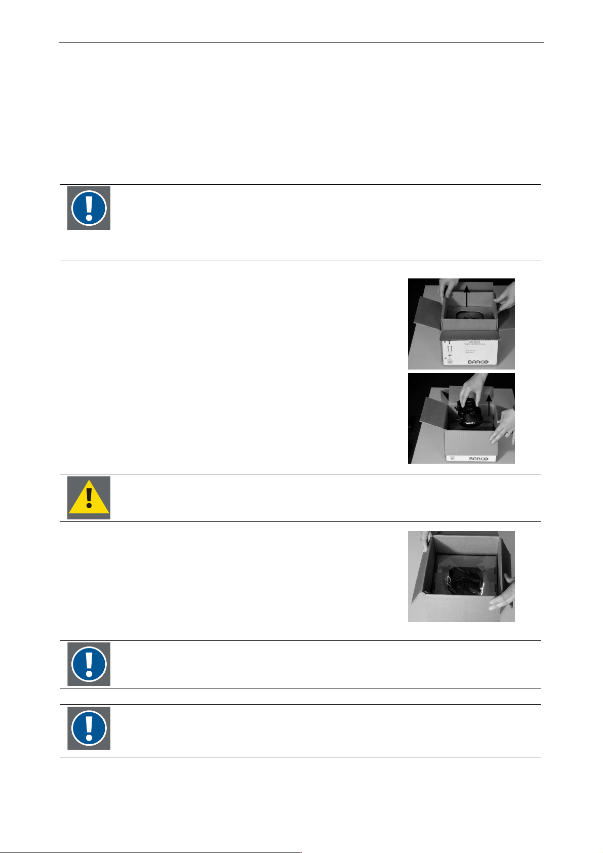
7. Maintenance and servicing
7.3.2 Unpacking a lamp module
The packaging product uses a strong, highly-resilient low-slip film to surround the lamp module, protecting it
from shock and vibration.
The lamp module is packed between two layers of highly resilient low-slip film. The resilient suspension film is
tough and retains its effectiveness for return shipments and multiple uses.
To ensure that the lamp module is held securely in place the upper layer is pressed against the lamp module and
will pop up when the adhesive tape of the package is removed. Do not jump!
To ensure that the lamp module is held securely in place the upper layer is pressed against
the lamp module and will pop up when the adhesive tape of the package is removed. Do not
jump!
Caution: Don't touch the glass top of the reflector!
Place the cardboard box upright according to the instruction printed on the
box.
Remove the adhesive tape. Be aware that the upper layer will pop up!
Open the box and remove the upper layer.
Take hold of the lamp and lift it out.
Take care that you don't touch the glass top of the reflector!
Now you can insert the lamp as described in the following chapter
If you accidentally made any fingerprints on the glass top of the reflector, clean the glass top
with alcohol before inserting the lamp module!
After the lamp is removed, put the upper layer back in the box. Save the entire
package in case the lamp has to be shipped again.
To ship the lamp module, use the original package and re-pack the lamp module between the
two layers of highly resilient low-slip film.
To pack the lamp module, proceed in the reversed order, please! Don't touch the glass top of
the reflector! Take hold on the fitting and place the lamp module upside down onto the lower
layer. Press the upper layer firmly against it, "opening" on top side, and close the box with
adhesive tape!
Barco - OverView D series - Doc-3353-2 - user's manual - Revision 04 - April 2005
________________________________________________________________________
7-9
Page 71
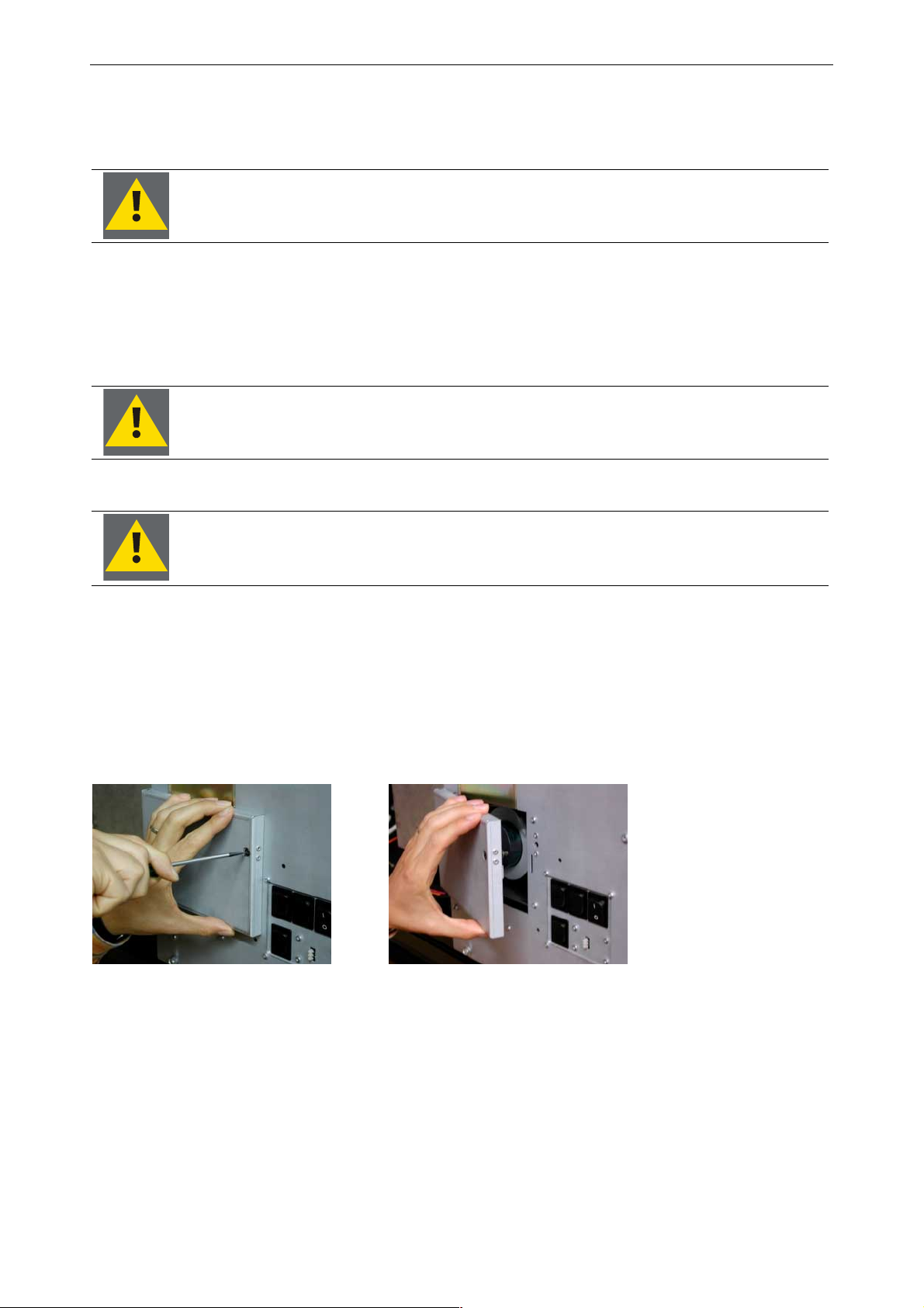
7. Maintenance and servicing
7.3.3 Illumination unit with 2x120W lamps or 2x100W lamps
The lamp module must be replaced if a fault occurs and if the lamp does not succeed in re-ignition again.
The cooling concept of OverView D requires that the lamp lift is always armed with two
lamps! Do not remove the broken lamp if there is no replacement for it!
With OverView D, lamps are hot swappable and can be replaced while the equipment is on. When opening the
lamp cover, the lamp driver will be disconnected, and there is no risk of electrical shock. However it is NOT recommended to open the lamp door if the lamp door LED does not show red.
Only open the lamp door when the lamp door LED shines red!
The hot lamp is at high pressure. Do not open the lamp housing before the lamp has
cooled down! Wait at least about 5 minutes after switching off the lamp.
Always hold the lamp by its socket, and never on the glass bulb or reflector! Use fabric
gloves when replacing!
7.3.3.1 Removing the lamp module
• Use a hexagon key size 3 (the key is provided with the system)
• To open the lamp door, a quarter turn counterclockwise will do
• Open the lamp door.
opening the lamp door
Figure 7-3
Barco - OverView D series - Doc-3353-2 - user's manual - Revision 04 - April 2005
_______________________________________________________________________
7-10
Page 72
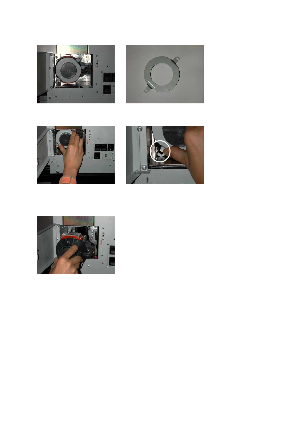
Now you can see the lamp, fixed into its position by means of a securing ring [1].
1
7. Maintenance and servicing
inside the lamp housing
• Press the securing ring, and turn it counterclockwise until the hooks are released from the guide rods.
the securing ring
• Remove the securing ring
• Withdraw the lamp module. While withdrawing, the plug is disconnected.
Figure 7-4
Figure 7-5
withdrawing the lamp module
Figure 7-6
7.3.3.2 Inserting a lamp module
The following description applies if the lamp has already been removed as described above and the lamp cover
is still opened.
• Fetch the lamp module on its housing. The power socket is on the right side.
• Insert the lamp carefully. Take care that the "tubes" slide on the guide rods [2].
Barco - OverView D series - Doc-3353-2 - user's manual - Revision 04 - April 2005
_______________________________________________________________________
7-11
Page 73
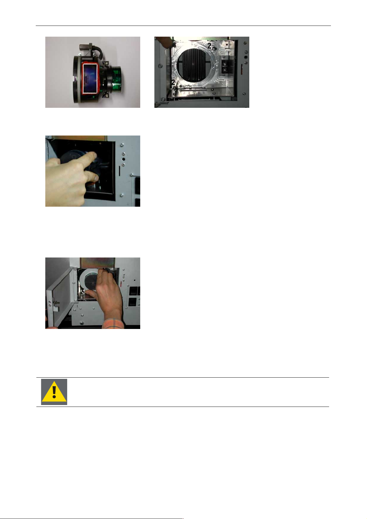
7. Maintenance and servicing
• Mind the position of the fingers: the force is to apply on the outer part of the module
applying the force on the lamp module
• Press the lamp module tightly into its socket
• Apply the securing ring on the lamp and press it while turning
• Turn the securing ring until its hooks click round the guide rods.
lamp and lamp housing
Figure 7-7
Figure 7-8
inserting the securing ring
• Close the lamp door
• Use the hexagon key and lock the lamp door by turning the screw a quarter turn clockwise.
The lamp door must not be open for more than 15 minutes. If not closed within this
period, the projector will show a warning, and then go to standby after another 5
minutes.
If the operation mode of the projector has been Hot Standby, the new lamp is immediately switched on.
Barco - OverView D series - Doc-3353-2 - user's manual - Revision 04 - April 2005
_______________________________________________________________________
Figure 7-9
7-12
Page 74
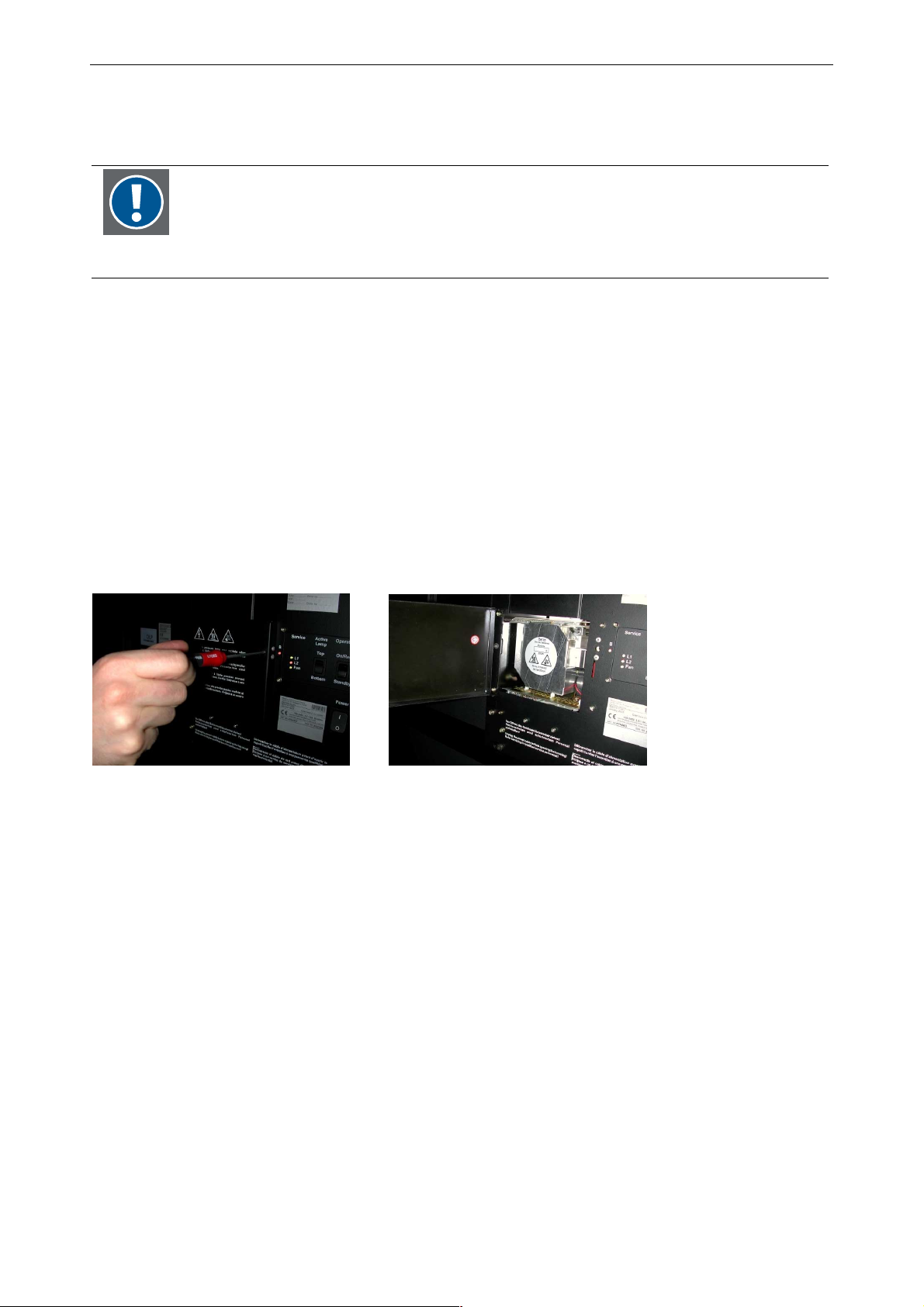
7. Maintenance and servicing
In case the operation mode has been Cold Standby or Auto switch, the lamp will be switched on automatically
in case it becomes the active lamp (i.e. in case of a lamp failure of the other lamp or after the switch cycle.
After the replacement of a lamp module, the new serial number has to be entered, and it is
highly recommended to select the lamp optimization procedure, cf. Reset runtime, Lamp
optimization.
In emergency cases the lamp optimization procedure can be skipped for the moment and carried out later.
7.3.4 Illumination unit with 2x200W lamps
Due to the higher light output of the 200W lamps compared to 100W lamps or 120W lamps, the illumination to
house the 2x200W lamp has a dedicated cooling concept. In addition the lamp modules are different.
The lamp module must be replaced if a fault occurs and if the lamp does not succeed in re-ignition again.
7.3.4.1 Removing the lamp module
• Use a hexagon key size 3 (the key is provided with the system)
• To open the lamp door, a quarter turn counterclockwise will do
• Open the lamp door.
opening the lamp door
Figure 7-10
Barco - OverView D series - Doc-3353-2 - user's manual - Revision 04 - April 2005
_______________________________________________________________________
7-13
Page 75
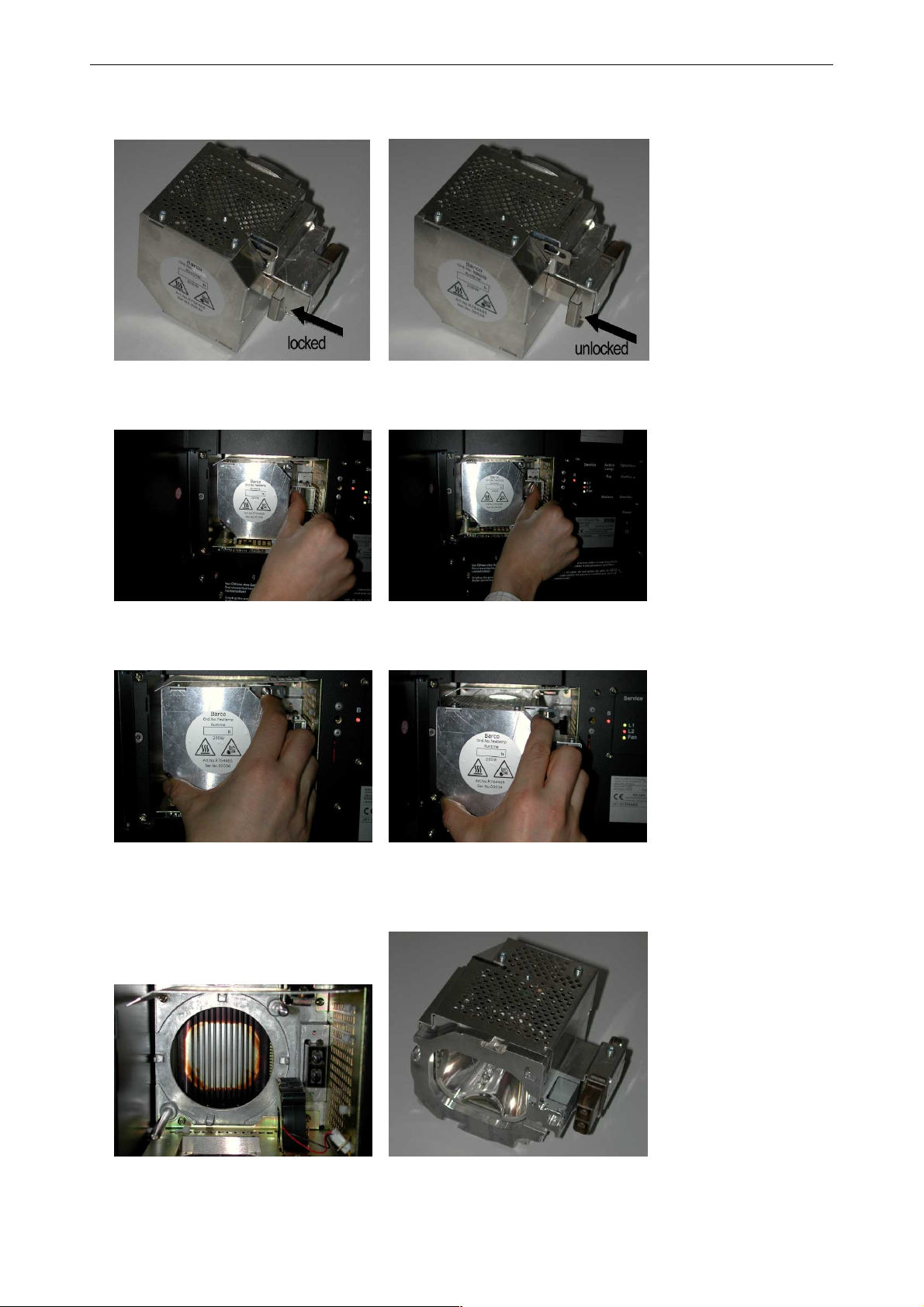
Now you can see the lamp, fixed into its position by means of a "locking slider".
• Push the locking slider to the right.
7. Maintenance and servicing
Figure 7-11
Position of slider
Figure 7-12
Locking slider
• Withdraw the lamp module. While withdrawing, the plug is disconnected.
withdrawing the lamp module
Figure 7-13
• When the lamp is removed, you see the two guiding rods on the upper right/lower left and the additional
fan for cooling.
Barco - OverView D series - Doc-3353-2 - user's manual - Revision 04 - April 2005
guiding rods and additional fan, lamp module with plug
Figure 7-14
_______________________________________________________________________
7-14
Page 76
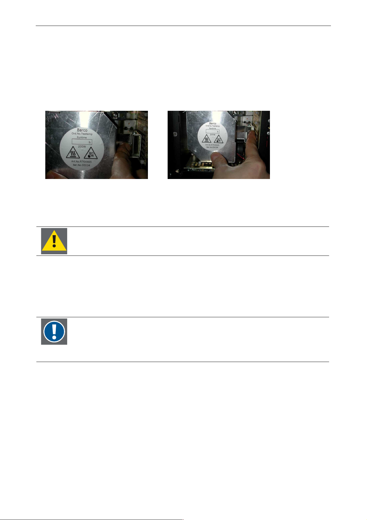
7. Maintenance and servicing
7.3.4.2 Inserting a lamp module
The following description applies if the lamp has already been removed as described above and the lamp cover
is still opened.
• Fetch the lamp module on its housing. The power socket is on the right side.
• Insert the lamp carefully. Take care that the "tubes" slide on the guide rods.
• Press the lamp module tightly into its socket.
• Lock the lamp into its position by pressing the locking slider to the left.
inserting the lamp and locking it
Figure 7-15
• Close the lamp door
• Use the hexagon key and lock the lamp door by turning the screw a quarter turn clockwise.
The lamp door must not be open for more than 15 minutes. If not closed within this
period, the projector will show a warning, and then go to standby after another 5
minutes.
If the operation mode of the projector has been Hot Standby, the new lamp is immediately switched on.
In case the operation mode has been Cold Standby or Auto switch, the lamp will be switched on automatically
in case it becomes the active lamp (i.e. in case of a lamp failure of the other lamp or after the switch cycle.
After the replacement of a lamp module, the new serial number has to be entered, and it is
highly recommended to select the lamp optimization procedure, cf. Reset runtime, Lamp
optimization.
In emergency cases the lamp optimization procedure can be skipped for the moment and carried out later.
Barco - OverView D series - Doc-3353-2 - user's manual - Revision 04 - April 2005
_______________________________________________________________________
7-15
Page 77
7.3.5 Disposing lamp modules
Note that there may be laws concerning disposal and recycling of burnt-out lamps in
your country! Please contact your local authorities to get further information!
7. Maintenance and servicing
Barco - OverView D series - Doc-3353-2 - user's manual - Revision 04 - April 2005
_______________________________________________________________________
7-16
Page 78
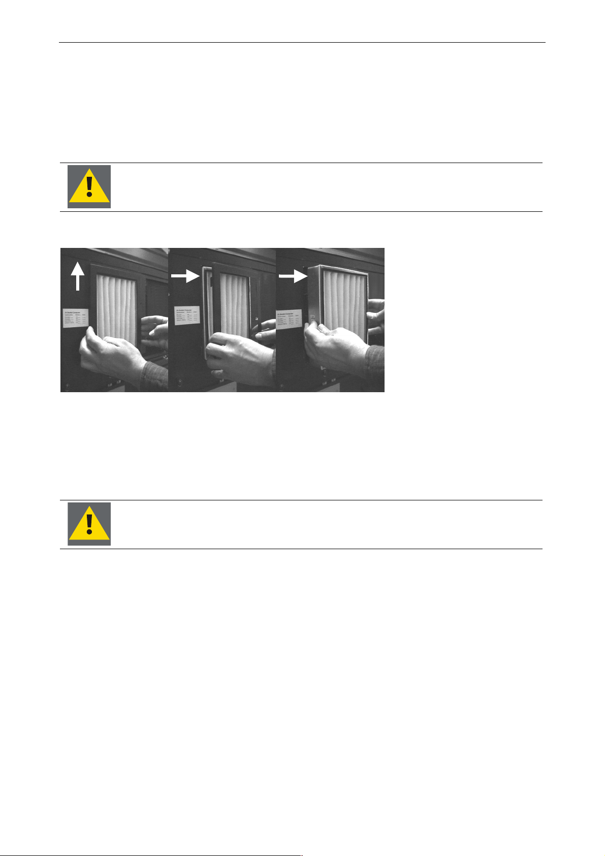
7. Maintenance and servicing
7.3.6 Replacing the filter pad
The filter pad must be replaced regularly. The operating period of a filter pad depends on the quality of the supplied air.
• Switch the projector in Standby mode.
• Switch off power by pressing OFF.
Switch off the equipment before replacing the filter pad in order to avoid severe
contamination of OverView D
• Lift the cover of the filter pad slightly and remove it.
• Remove the filter pad.
• Insert the new filter pad as indicated on its frame.
• Insert the cover of the filter pad and press it slightly down.
• Switch on power by pressing ON
Never push against a used air filter pad! The trapped dust particles will be released!
Removing the cover and the filter pad
Figure 7-16
Barco - OverView D series - Doc-3353-2 - user's manual - Revision 04 - April 2005
_______________________________________________________________________
7-17
Page 79

8. Technical data
8 Technical data
This chapter provides tabular overviews about the technical details of OVERVIEW D projection modules
Barco - OverView D series - Doc-3353-2 - user's manual - Revision 04 - April 2005
________________________________________________________________________
8-1
Page 80
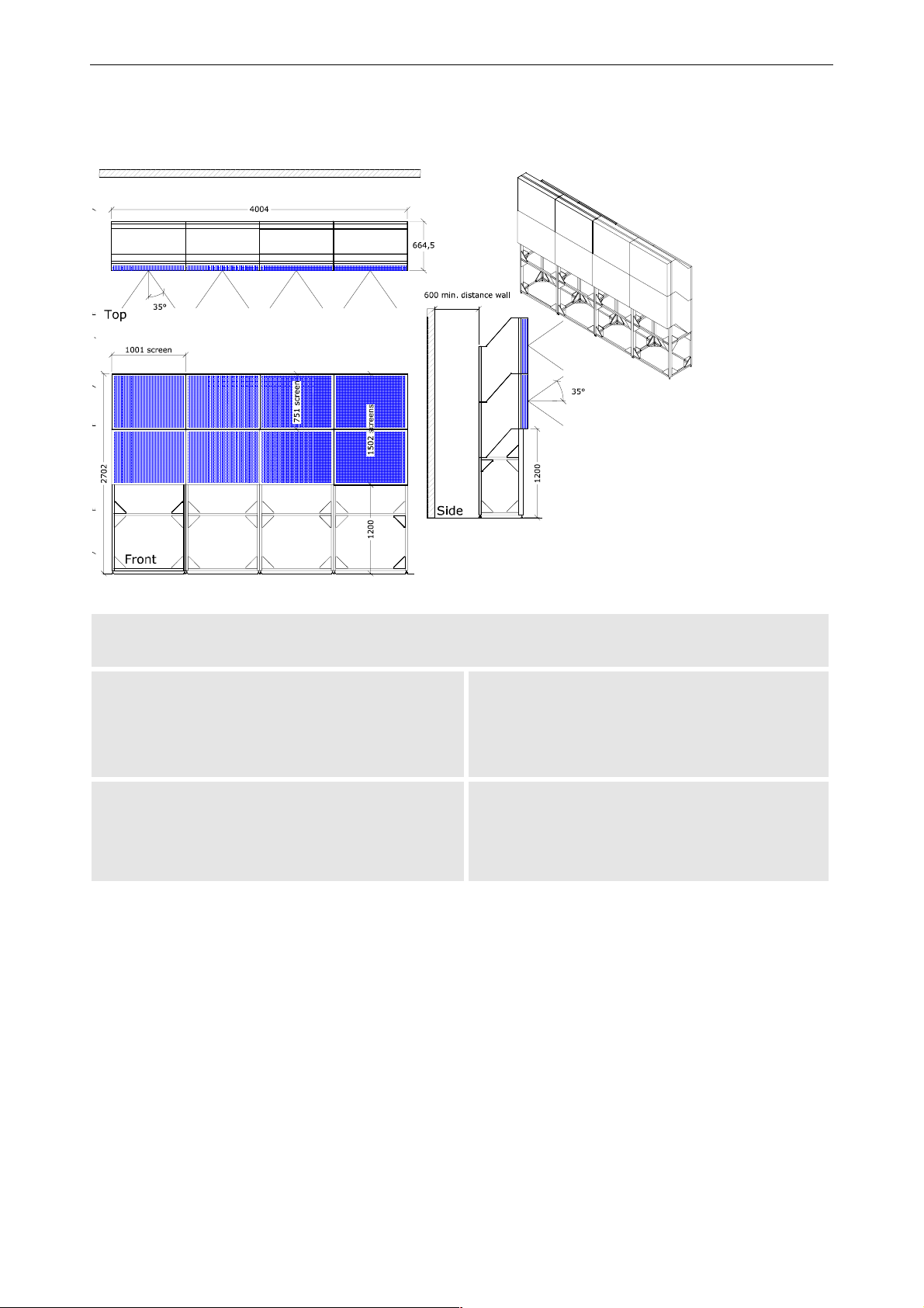
8.1 OverView mDG50-DL
8. Technical data
characteristic specification
OVERVIEW MDG50-DL
Dimensions
screen width
screen height
total depth
1000 mm | 39.4 in.
750 mm | 29.5 in.
665 mm | 26.2 in.
Weight
OverView mDG50-DL projection module
62.5 kg | 138 lbs
incl. illumination unit, projection unit, screen
Support (1000mm)
30 kg | 66.1 lbs
Barco - OverView D series - Doc-3353-2 - user's manual - Revision 04 - April 2005
________________________________________________________________________
8-2
Page 81
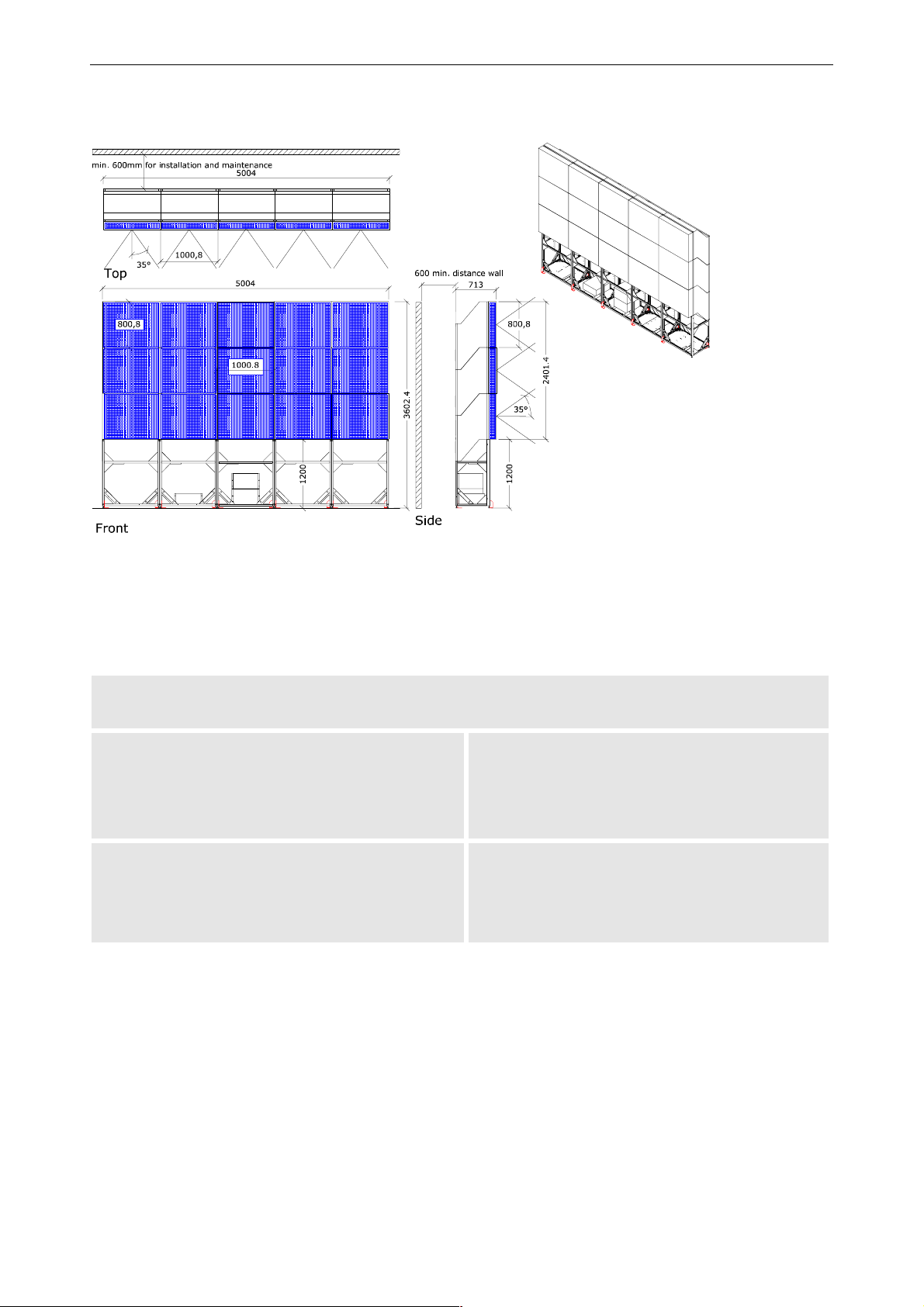
8.2 Overview mDR50-DL
8. Technical data
characteristic specification
OVERVIEW MDR50-DL
Dimensions
screen width
screen height
total depth
1001 mm | 39.4 in.
801 mm | 31.5 in.
713 mm | 28.1 in.
Weight
OverView mDR50-DL projection module
65 kg | 143.3 lbs
incl. illumination unit, projection unit, screen
Support (1200mm)
38 kg | 83.77 lbs
Barco - OverView D series - Doc-3353-2 - user's manual - Revision 04 - April 2005
________________________________________________________________________
8-3
Page 82
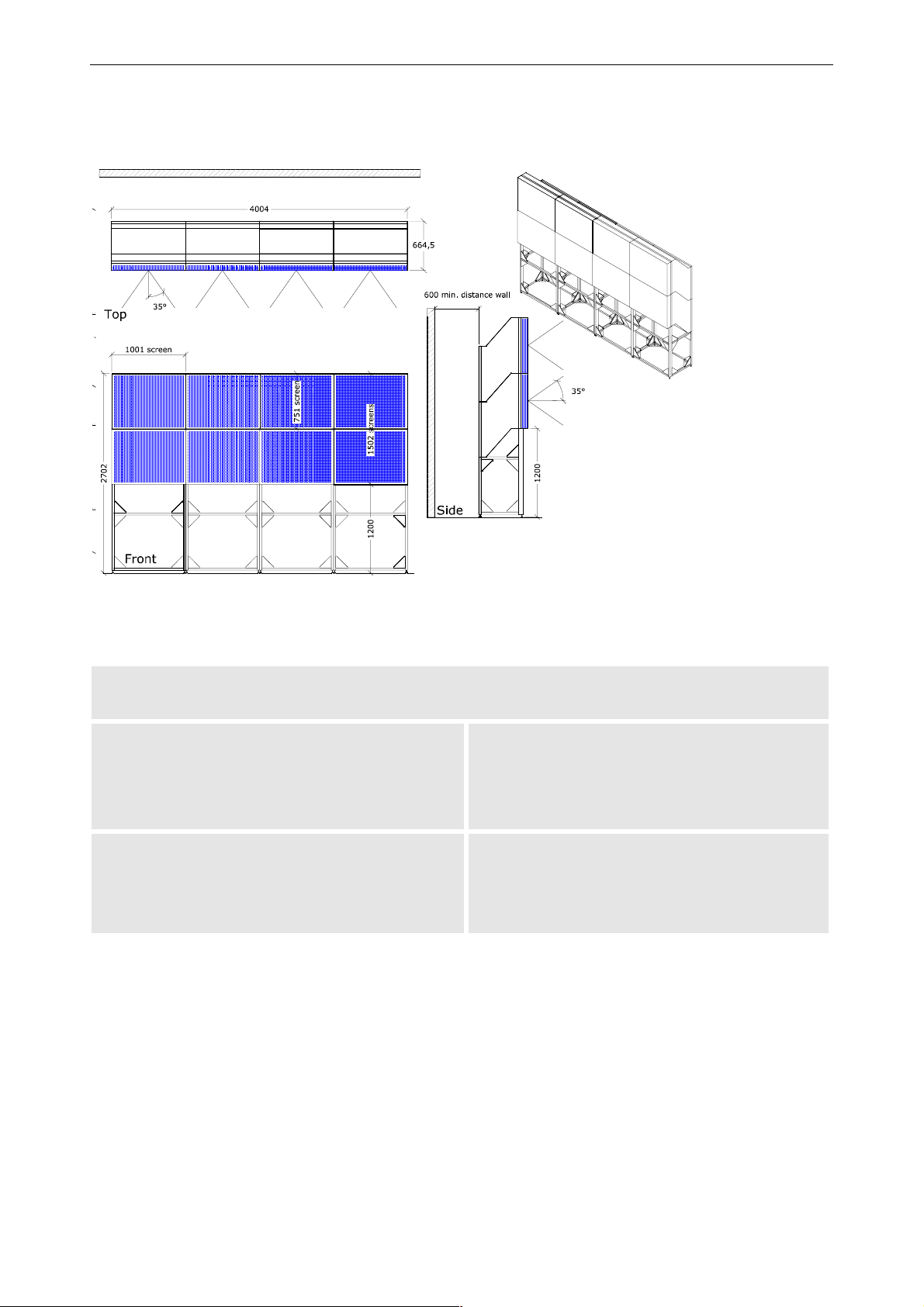
8.3 OverView mDR+50-DL
8. Technical data
characteristic specification
OVERVIEW MDR+50-DL
Dimensions
screen width
screen height
total depth
1000 mm | 39.4 in.
750 mm | 29.5 in.
665 mm | 26.2 in.
Weight
OverView mDR+50-DL projection module
62.5 kg | 138 lbs
incl. illumination unit, projection unit, screen
Support (1000mm)
30 kg | 66.1 lbs
Barco - OverView D series - Doc-3353-2 - user's manual - Revision 04 - April 2005
________________________________________________________________________
8-4
Page 83
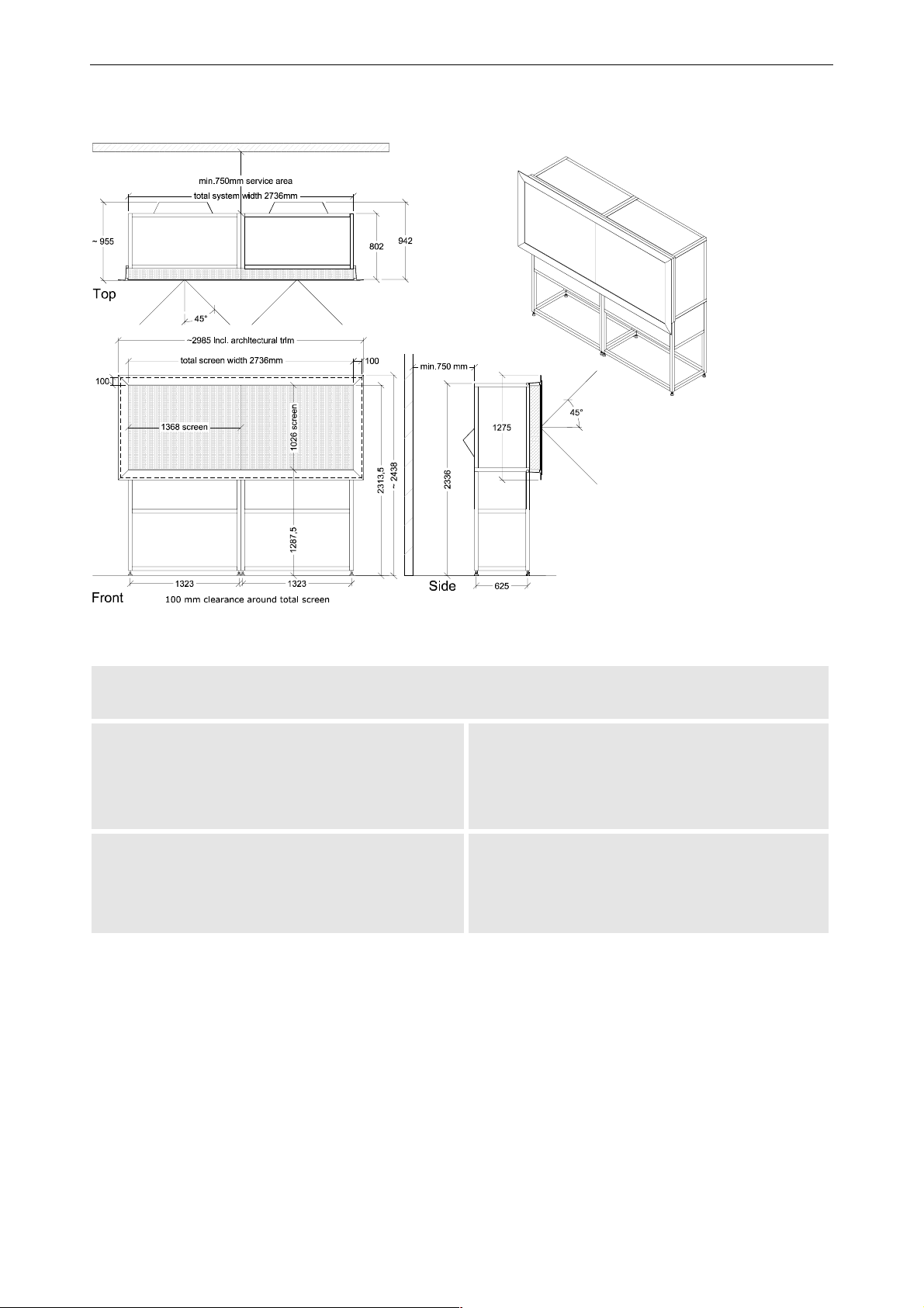
8.4 OverView cDG67-DL
8. Technical data
characteristic specification
OVERVIEW CDG67-DL
Dimensions
screen width
screen height
total depth
1368 mm | 53.86 in.
1026 mm | 40.4 in.
954 mm | 37.56 in.
Weight
OverView cDG67-DL projection module
incl. illumination unit, projection unit, screen
Support, standard height (1288mm)
140 kg | 308.64 lbs
60 kg | 132.28 lbs
Barco - OverView D series - Doc-3353-2 - user's manual - Revision 04 - April 2005
________________________________________________________________________
8-5
Page 84
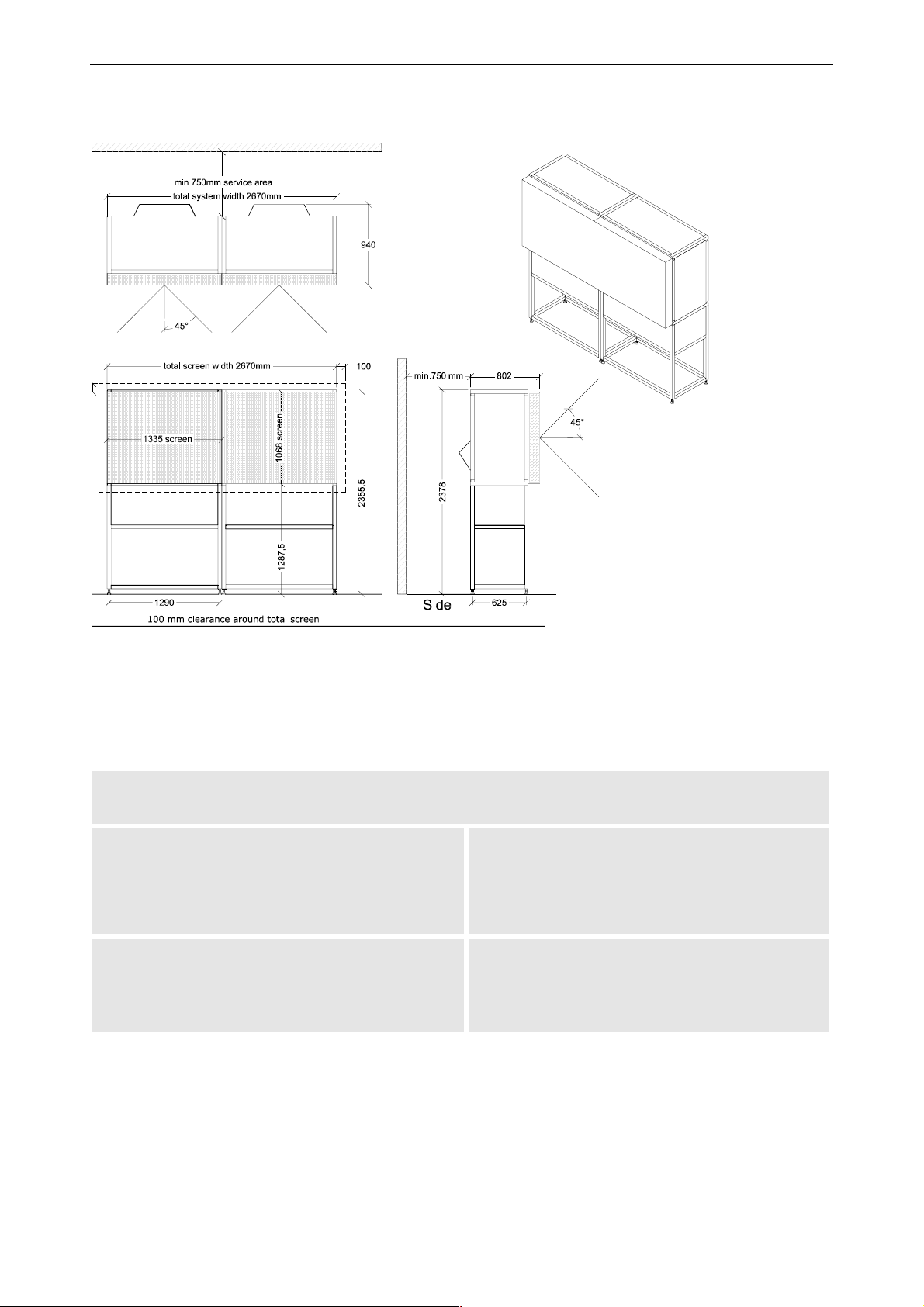
8.5 OverView cDR67-DL
8. Technical data
characteristic specification
OVERVIEW CDR67-DL
Dimensions
screen width
screen height
total depth
1335 mm | 52.56 in.
1068 mm | 42.04 in.
954 mm | 37.56 in.
Weight
OverView cDR67-DL projection module
140 kg | 308.64 lbs
incl. illumination unit, projection unit, screen
support, standard height (1288mm)
Barco - OverView D series - Doc-3353-2 - user's manual - Revision 04 - April 2005
60 kg | 132.28 lbs
________________________________________________________________________
8-1
Page 85
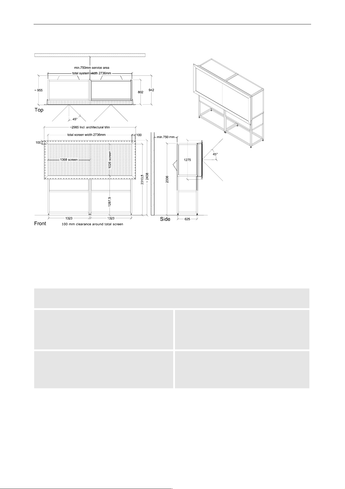
8.6 OverView cDR+67-DL
8. Technical data
characteristic specification
OVERVIEW CDR+67-DL
Dimensions
screen width
screen height
total depth
1368 mm | 53.86 in.
1026 mm | 40.4 in.
954 mm | 37.56 in.
Weight
OverView cDR+67-DL projection module
incl. illumination unit, projection unit, screen
Support, standard height (1288mm)
Barco - OverView D series - Doc-3353-2 - user's manual - Revision 04 - April 2005
140 kg | 308.64 lbs
60 kg | 132.28 lbs
________________________________________________________________________
8-2
Page 86
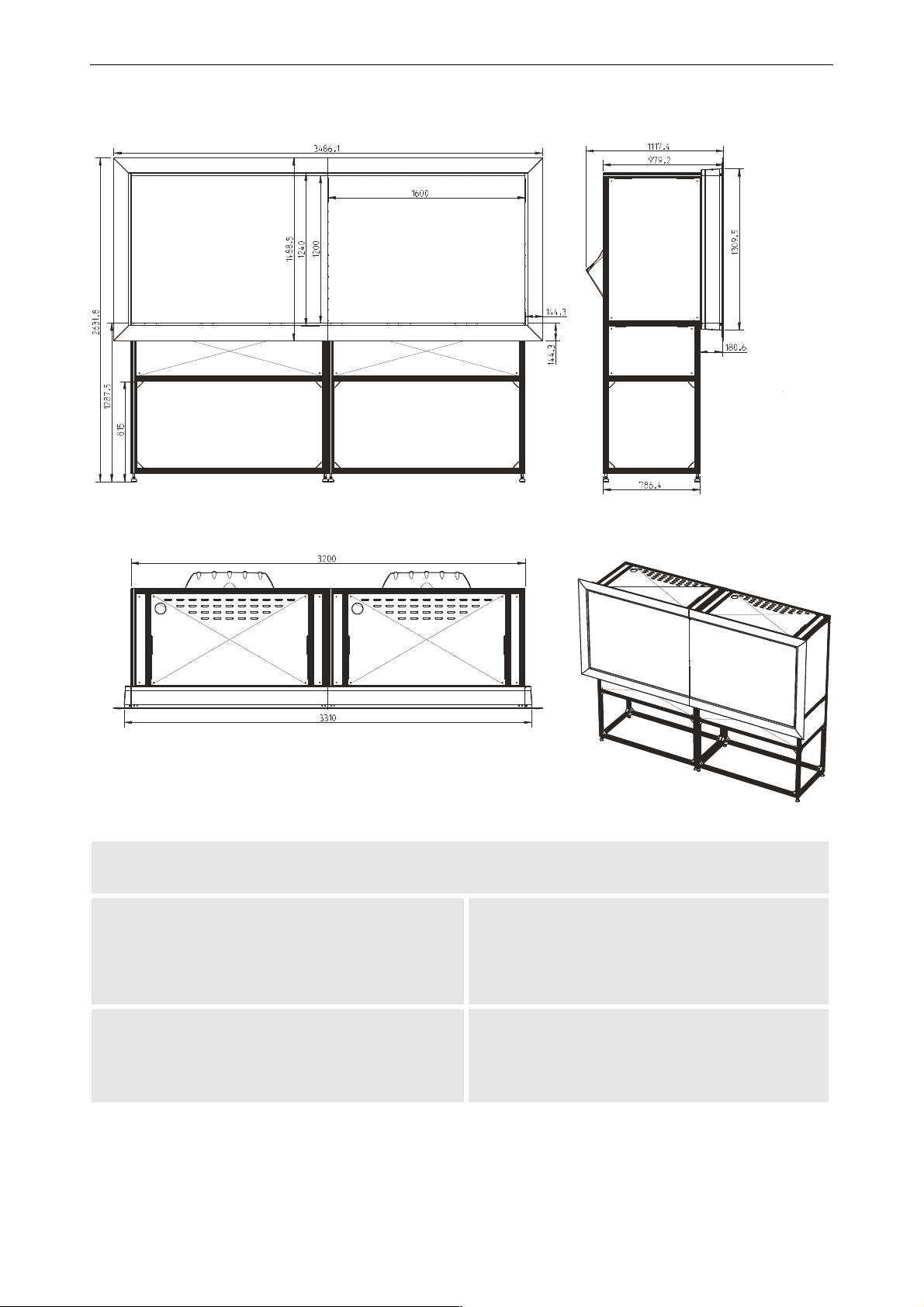
8.7 OverView cDG80-DL
8. Technical data
characteristic specification
OVERVIEW CDG80-DL
Dimensions
screen width
screen height
total depth
1600mm | 63in.
1200mm | 47.25in.
1117.4mm | 44in.
Weight
OverView cDG80-DL projection module
128kg | 282.19lbs
incl. illumination unit, projection unit, screen
support, standard height (1288mm)
Barco - OverView D series - Doc-3353-2 - user's manual - Revision 04 - April 2005
60kg | 132.28lbs
________________________________________________________________________
8-1
Page 87
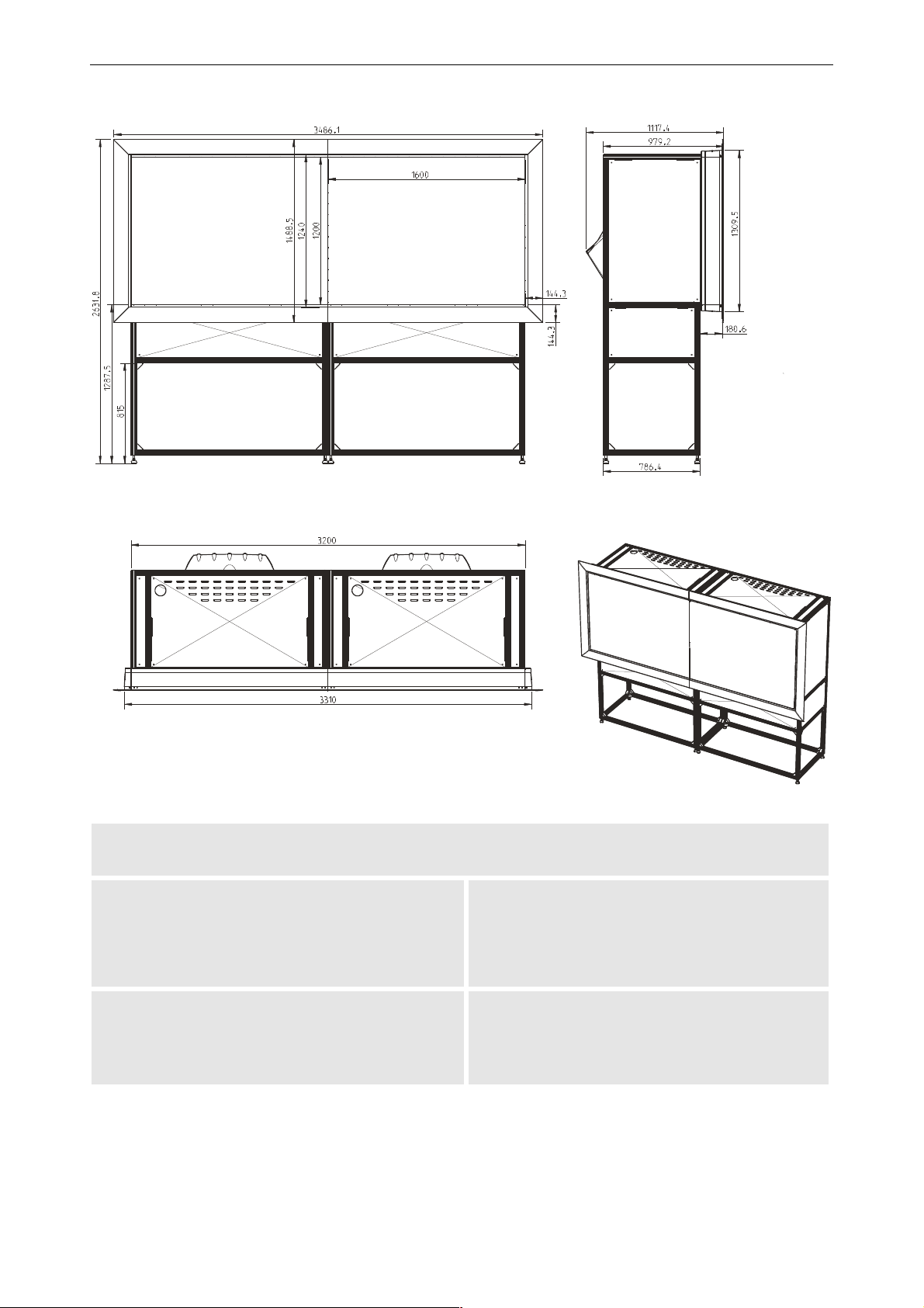
8.8 OverView cDR+80-DL
8. Technical data
characteristic specification
OVERVIEW CDR+80-DL
Dimensions
screen width
screen height
total depth
1600mm | 63in.
1200mm | 47.25in.
1117.4mm | 44in.
Weight
OverView cDR+80-DL projection module
128kg | 282.19lbs
incl. illumination unit, projection unit, screen
support, standard height (1288mm)
Barco - OverView D series - Doc-3353-2 - user's manual - Revision 04 - April 2005
60kg | 132.28lbs
________________________________________________________________________
8-2
Page 88

8. Technical data
8.9 Electrical data illumination unit 120 W
characteristic specification
Lamp 2x120 Watt UHP™ lamp, nominal lifetime 2x6000 hours
AC power supply 100-240 V
Mains frequency 60/50 Hz
Current hot standby 3.5 A – 1.5 A
Current cold standby 2.1 A – 0.95 A
Power consumption hot standby 350 W
Power consumption cold standby 210 W
8.10 Optical data illumination unit 120 W, projection unit XGA resolution
characteristic specification
Resolution XGA resolution (1024×768 pixels)
Colors 16.7 millions
Brightness uniformity > 95%
Brightness 675 lumens (typ.)
Contrast 1300:1
8.11 Optical data illumination unit 120 W, projection unit SXGA resolution
characteristic specification
Resolution SXGA resolution (1280×1024 pixels)
Colors 16.7 millions
Brightness uniformity > 95%
Brightness 650 lumens (typ.)
Contrast 750:1
8.12 Optical data illumination unit 120 W, projection unit SXGA+ resolution
characteristic specification
Resolution SXGA+ resolution (1400×1050 pixels)
Colors 16.7 millions
Brightness uniformity > 95%
Brightness 800 lumens (typ.)
Contrast 1600:1
Barco - OverView D series - Doc-3353-2 - user's manual - Revision 04 - April 2005
________________________________________________________________________
8-3
Page 89

8. Technical data
8.13 Electrical data illumination unit 100 W
characteristic specification
Lamp 2x100 Watt UHP™ lamp, nominal lifetime 2x10000 hours
AC power supply 100-240 V
Mains frequency 60/50 Hz
Current hot standby 3.5 A – 1.5 A
Current cold standby 2.1 A – 0.95 A
Power consumption hot standby 285 W
Power consumption cold standby 190 W
8.14 Optical data illumination unit 100 W, projection unit XGA resolution
characteristic specification
Resolution XGA resolution (1024×768 pixels)
Colors 16.7 millions
Brightness uniformity > 95%
Brightness 550 lumens (typ.)
Contrast 1300:1
8.15 Optical data illumination unit 100 W, projection unit SXGA resolution
characteristic specification
Resolution SXGA resolution (1280×1024 pixels)
Colors 16.7 millions
Brightness uniformity > 95%
Brightness 530 lumens (typ.)
Contrast 750:1
8.16 Optical data illumination unit 100 W, projection unit SXGA+ resolution
characteristic specification
Resolution SXGA+ resolution (1400×1050 pixels)
Colors 16.7 millions
Brightness uniformity > 95%
Brightness 650 lumens (typ.)
Contrast 1600:1
Barco - OverView D series - Doc-3353-2 - user's manual - Revision 04 - April 2005
________________________________________________________________________
8-4
Page 90

8.17 Optical data illumination unit 200 W, projection unit XGA resolution
characteristic specification
Lamp
AC power supply 240 V
Mains frequency 50 Hz
Current cold standby / hot standby 1.2A / 2.1A
Power consumption
cold standby / hot standby 290W/520W
Resolution XGA resolution (1024×768 pixels)
Colors 16.7 millions
Brightness uniformity > 90%
Brightness 1125 lumen (typ.)
2x200 Watt P-VIP200/1,3cP22 lamp, nominal lifetime 2x2000
hours
8. Technical data
Contrast 1300:1
8.18 Use of 3200K filter cartridge
characteristic specification
Brightness Reduced to about 58% compared to the brightness without
filter
8.19 Operating conditions
characteristic specification
Humidity Up to 80%, non-condensing*)
Temperature 0-40°C | 32°F – 105°F*)
*)
for OverView cD67 and OverView cD80 temperature range and
humidity depending on the overall configuration
Barco - OverView D series - Doc-3353-2 - user's manual - Revision 04 - April 2005
________________________________________________________________________
8-5
Page 91
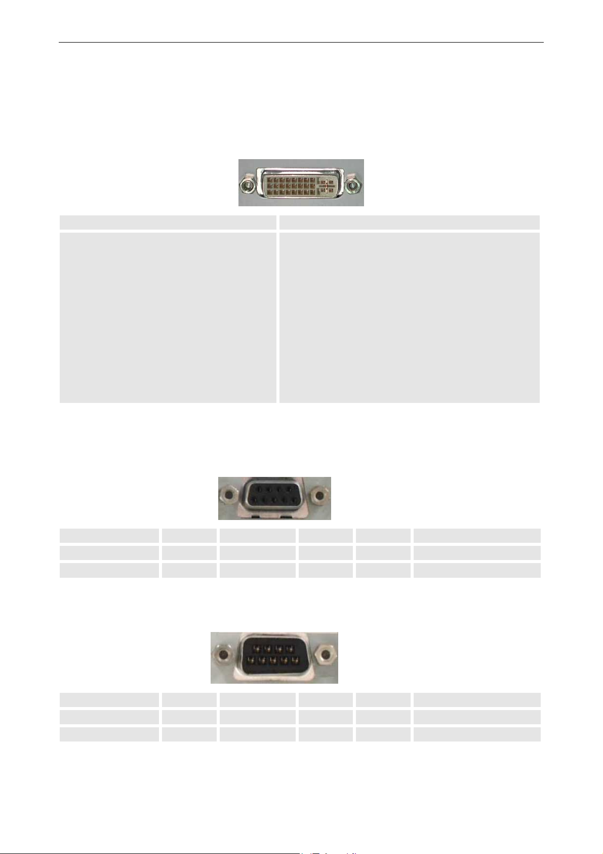
8.20 Interfaces
8.20.1 Data
DVI
Pin Signal Assignment Pin Signal Assignment
1 TMDS Data 2- 13 2 TMDS Data 2+ 14 3 TMDS Data 2 Shield 15 Ground (+5, Analog /V Sync)
4 - 16 5 - 17 TMDS Data 06 DDC Clock 18 TMDS Data 0+
7 DDC Data 19 TMDS Data 0 Shield
8 - 20 9 TMDS Data 1- 21 10 TMDS Data 1+ 22 TMDS Clock Shield
11 TMDS Data 1 Shield 23 TMDS Clock +
12 - 24 TMDS Clock -
8. Technical data
8.20.2 Remote Control
RS232 In
1 - 4 - 7 -
2 TXD 5 GND 8 -
3 RXD 6 - 9 -
RS232 Out
1 - 4 - 7 -
2 RXD 5 GND 8 -
96
1
6
1
5
9
5
3 TXD 6 - 9 -
Barco - OverView D series - Doc-3353-2 - user's manual - Revision 04 - April 2005
________________________________________________________________________
8-6
Page 92
8.21 Scope of delivery
designation order No.
OVERVIEW MDG50-DL R9842480
OVERVIEW MDR50-DL R9842490
OVERVIEW MDR+50-DL R9842491
8. Technical data
Option: curved setup, 5degrees
R9860709
50" system
Option: curved setup, 8degrees
R9860708
50" system
Support Standard 875mm,
RSPSI28491
50" system
Support Standard 1000mm,
RSPSI28494
50" system
Support Standard 1200mm,
RSPSI28493
50" system
OVERVIEW CDG67-DL R9860701
OVERVIEW CDR67-DL R9860702
OVERVIEW CDR+67-DL R9842580
OVERVIEW CDG80-DL R9842510
OVERVIEW CDR+80-DL R9852830
Option: curved setup, 3degrees
R9860703
OverView cD
Option: curved setup, 5degrees
R9860704
OverView cD
Option: curved setup, 8degrees
R9860705
OverView cD
Support Standard, up to 1500mm
R9860706
OverView cD
Option: Illumination Unit 100W R9842500
Option: Illumination Unit 200W
R9842740
(XGA, 240V)
Barco - OverView D series - Doc-3353-2 - user's manual - Revision 04 - April 2005
________________________________________________________________________
8-7
Page 93
8.22 Consumables
The following parts can be ordered as consumables:
designation order No.
lamp module 120W R9842020
lamp module 100W R9842440
lamp module 200W R9842760
Filter R9842800
8.23 Spare parts
The following parts can be ordered as spare parts:
designation order No.
Fan Box Repair Kit RSDLP32790
Illumination Unit 120W R9842650
Illumination Unit 100W R9842460
8. Technical data
Illumination Unit 200W R9842470
Projection Unit XGA R9841921
Projection Unit SXGA R9841920
Projection Unit SXGA+ R9842670
8.24 Controller
For information about the controllers, contact Barco Control Rooms GmbH, please!
Barco - OverView D series - Doc-3353-2 - user's manual - Revision 04 - April 2005
________________________________________________________________________
8-8
Page 94

8.25 Addresses
• Barco Control Rooms GmbH
An der Rossweid 5 • D-76229 Karlsruhe • Germany
Phone (49) (721) 6201-0 • Fax (49) (721) 6201-298
E-mail [email protected], Web www.barcocontrolrooms.de
• Barco N.V. Projection Systems
Noordlaan 5 • B-8520 Kuurne • Belgium
Phone (32) (56) 36-8211 • Fax (32) (56) 36-8251
E-mail [email protected] • Web www.barcocontrolrooms.com
8. Technical data
Barco - OverView D series - Doc-3353-2 - user's manual - Revision 04 - April 2005
________________________________________________________________________
8-9
Page 95

9 Trouble shooting
9. Trouble shooting
Barco - OverView D series - Doc-3353-2 - user's manual - Revision 04 - April 2005
________________________________________________________________________
9-1
Page 96

9. Trouble shooting
9.1 LED indication
In case of a mal function of OVERVIEW D, please check the LED indication first, cf. Manual user interface.
Barco - OverView D series - Doc-3353-2 - user's manual - Revision 04 - April 2005
________________________________________________________________________
9-2
Page 97

9.2 Hot line
Feel free to contact us if you have any further questions!
• Barco N.V. Projection Systems - Europe
Noordlaan 5, B-8520 Kuurne
Phone: +32-56-368-211, Fax: +32-56-368-251
E-mail: [email protected], Web: www.barcocontrolrooms.com
9. Trouble shooting
Barco - OverView D series - Doc-3353-2 - user's manual - Revision 04 - April 2005
________________________________________________________________________
9-3
Page 98

10. Configuring notes
10 Configuring notes
A number of design and ergonomic conditions must be considered when planning the installation of OVERVIEW D.
In addition to mounting dimensions, the following sections also include anthropotechnical requirements which
must be observed in a specific application.
Barco - OverView D series - Doc-3353-2 - user's manual - Revision 04 - April 2005
_______________________________________________________________________
10-1
Page 99

10. Configuring notes
10.1 Floor space and maintenance area
Sufficient floor space and maintenance area must be available when installing OVERVIEW DL
Floor Space
The floor space must have a sufficient load carrying capacity and be sufficiently flat (according to DIN 18202). It
must not sag by more than 1 millimeter under the load of the
VERVIEW D Display Wall. A cement, wood or false floor is permissible.
O
The load of the O
No installations (venting ducts, sockets etc.) must be present in the floor in the area of the feet or of the lower
anchoring devices. An area of at least 15 centimeters must be kept free around each foot. The loading capacity in
the area of the feet must be sufficient. Height differences up to ±5 millimeters can be compensated using the
adjustable feet.
VERVIEW D is transmitted to the floor via adjustable feet.
Barco - OverView D series - Doc-3353-2 - user's manual - Revision 04 - April 2005
_______________________________________________________________________
10-2
Page 100
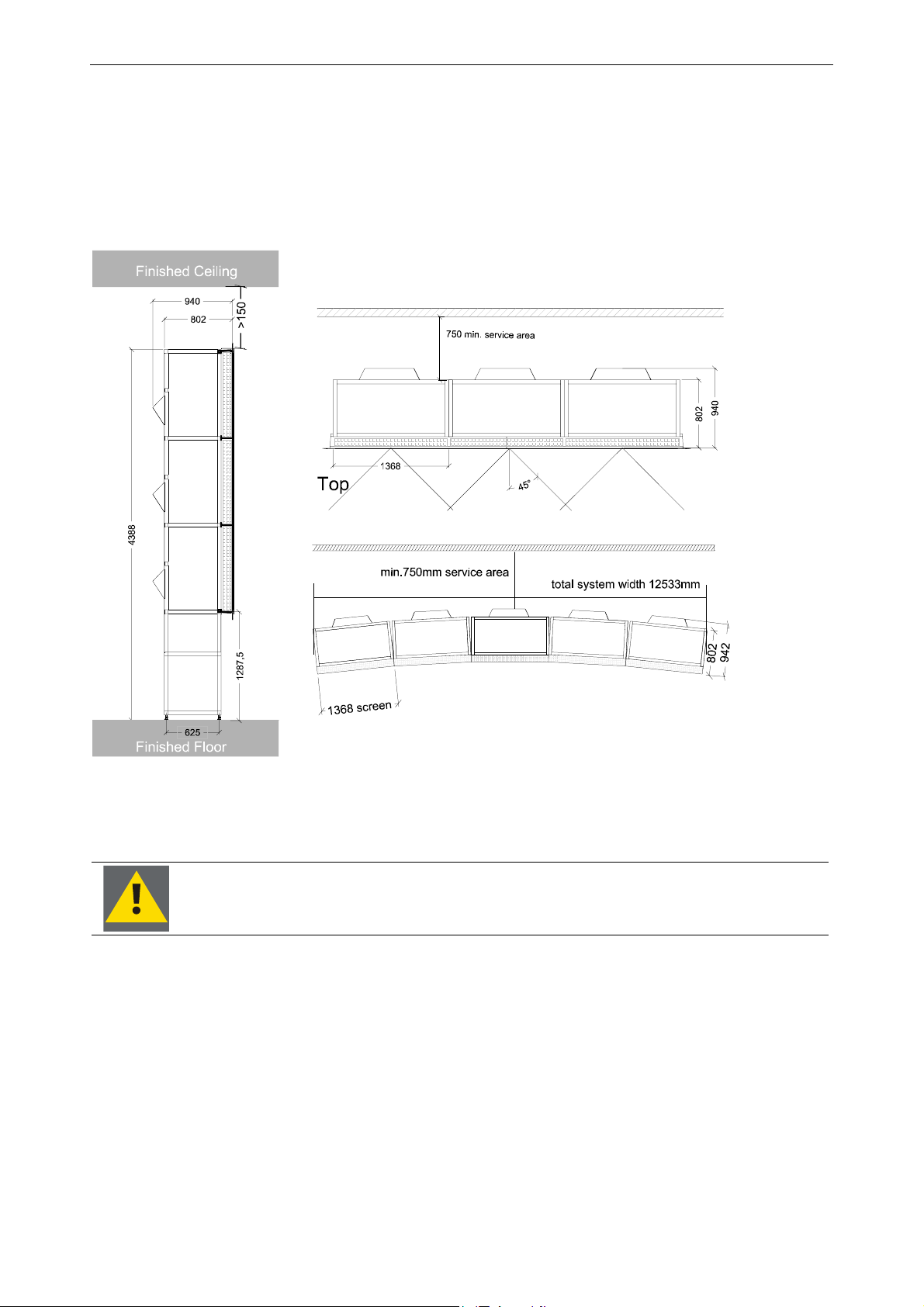
10. Configuring notes
Maintenance area
The floor space for OverView D is calculated from the basic area of the structure. A maintenance area must be
provided behind each OverView D over the complete width. This area must be permanently accessible. The exact
regulations for such a maintenance area can be obtained from the specifications for working premises. The following picture refers to OverView cDG67-DL.
Linear and polygonal set-up of OverView cDG67-DL
(All dimensions measured in millimeters!)
Figure 10-1
With regards to maintenance area, please note that there may be laws concerning safety standards in your country!
The OVERVIEW D Display Wall can have a linear or curved arrangement. Standard curved configurations are available with with angles of 3, 5, and 8 degrees for OverView cD, or 5 and 8 degrees for 50" systems..
Other angles on request!
Barco - OverView D series - Doc-3353-2 - user's manual - Revision 04 - April 2005
_______________________________________________________________________
10-3
 Loading...