

Page 1
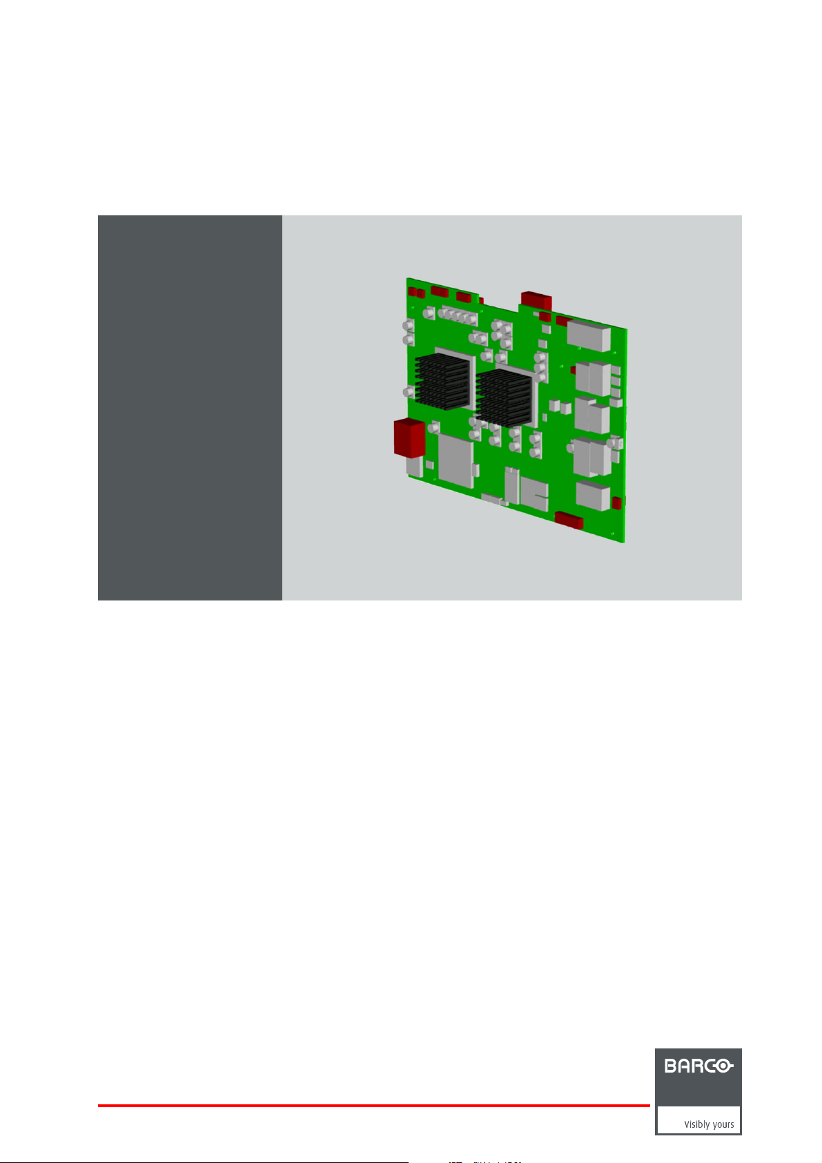
PMP kit
Installation manual
Galaxy NH-12, NW-12, Galaxy NW-12
R7649672K
R7649676K
R59770498/01
28/02/2011
Page 2

Barco nv Simulation Division
Noordlaan 5, B-8520 Kuurne
Phone: +32 56.36.82.11
Fax: +32 56.36.84.86
E-mail: info@barco.com
Visit us at the web: www.barco.com
Printed in Belgium
Page 3

Changes
Barco provides this manual ’as is’ without warranty of any kind, either expressed or implied, including but not limited to the implied warranties or merchantability and fitness for a particular purpose. Barco may make improvements and/or changes to the product(s) and/or the
program(s) described in this publication at any time without notice.
This publication could contain technical inaccuracies or typographical errors. Changes are periodically made to the information in this
publication; these changes are incorporated in new editions of this publication.
Copyright ©
All rights reserved. No p a rt of this document may be copied, reproduced or translated. It shall not other
stored in a retrieval s ystem without the prior written consent of Barco.
wise be recorded, transmitted or
Disposal Information
This equipment has required the extraction and use of natural resources for its production. It may contain hazardous substances for health
and env ironme nt. In order to avoid the dissemination of those subs tances in the environment and to diminish the pressure on natural
resources, we encourage you to use the appropriate take-back systems. Those systems will reuse or recycle most of the materials of your
end of life equipment in a sound way.
The crossed-out wheeled bin symbol invites you to use those s ystems. If you need more information on the collection, reuse and recycling
systems, please contact your local or regional waste administrator. You can also contact u s for more information on the environmental
performances of our products.
Guarantee and Compensation
Barco provides a guarantee relating to perfect man ufacturing as
must im mediately inspect all delivered goods for damage incurred during transport, as well as for material and manufacturing faults Barco
must be informed immediately in writing of any complaints.
The period of guarantee begins on the date of transfer of risks, in the case of special systems and software on the date of commissioning,
at latest 30 days after th e transfer of risks. In the event of justified notice of complaint, Barco can repair the fault or provide a replacement
at its own discretion within an appropriate period. If this measure proves to be impos sible or unsuccessful, the purchaser ca n demand a
reduction in the purchase price or cancellation of the contract. All other claims, in particular those relating to compensa tion for direct or
indirect damage, and also da mage attributed to the operation of software as well as to other services provided by Barco, being a component
of the system or independent service, will be deemed invalid provided the damage is not proven to be attributed to the absence of properties
guaranteed in writing or due to the intent or gross negligence or part of Barco.
If the purchaser or a third party carries out modifications or repairs on goods delivered by B arco, or if the goods are ha ndled incorrectly,
in particular if the systems are commissioned operated incorrectly or if, after the transfer of risks, the goods are subject to influences not
agreed upon in the contract, all guarantee claims of the purchaser will be r endered invalid. Not inc luded in the guarantee coverage are
system failures which are attributed to programs or special electronic circuitry provided by the purchaser, e.g. interfaces. Normal wear as
well as normal maintenance are not subject to the guarantee provided by Barco either.
The enviro nmental conditions as well as the servicing and maintenance regulations specified in the this manual must be complied with by
the customer.
part of the legally stipulated terms of guarantee. On receipt, the pu rchaser
Trademarks
Brand and product name s mentioned in
All brand and product names mentioned in this manual serve as comments or examples and are not to be understood as advertising for
the products or their m anufacturers.
this manual may be trademarks, registered trademarks or c opyrights of their respective holders.
Page 4

Page 5

Table of contents
TABLE OF CONTENTS
1. Safety instructions ................................................................................................. 3
1.1 Safety during kit installation .......................................................................................................... 3
2. PMP kit ............................................................................................................... 5
2.1 Introduction ........................................................................................................................... 5
2.2 Kit description......................................................................................................................... 5
2.3 Kit installation (overview)............................................................................................................. 5
3. Kit installation (detailed) ................ ................ ................ ................ ................ .......... 7
3.1 Making a backupof the PMP to be replaced ........................................................................................ 7
3.2 Replacing the faulty PMP ............................................................................................................ 7
3.2.1 Removing the input module ................................................................................................... 7
3.2.2 Removing the PMP ............................................................................................................ 8
3.2.3 Installing the PM P .............................................................................................................10
3.2.4 Installing the input module . ................................................................................................... 12
3.3 Restoring the backup................................................................................................................ 13
3.4 Upgrade the projector to the desired software version............................................................................. 13
A. Backup and restore data ..........................................................................................15
A.1 Connecting to the projector through Projector Suppo rt . ........................................................................... 15
A.2 Making a backupof the projector’s key data ....................................................................................... 18
A.3 Restoring a set of key data.......................................................................................................... 21
Index..................... ................ .................. ................ ................ ................ ............... 31
R59770498 PMP KIT 28/02/2011 1
Page 6

Table of contents
2 R59770498 PMP KIT 28/02/2011
Page 7
1. SAFETY INSTRUCTIONS
1.1 Safety during kit installation
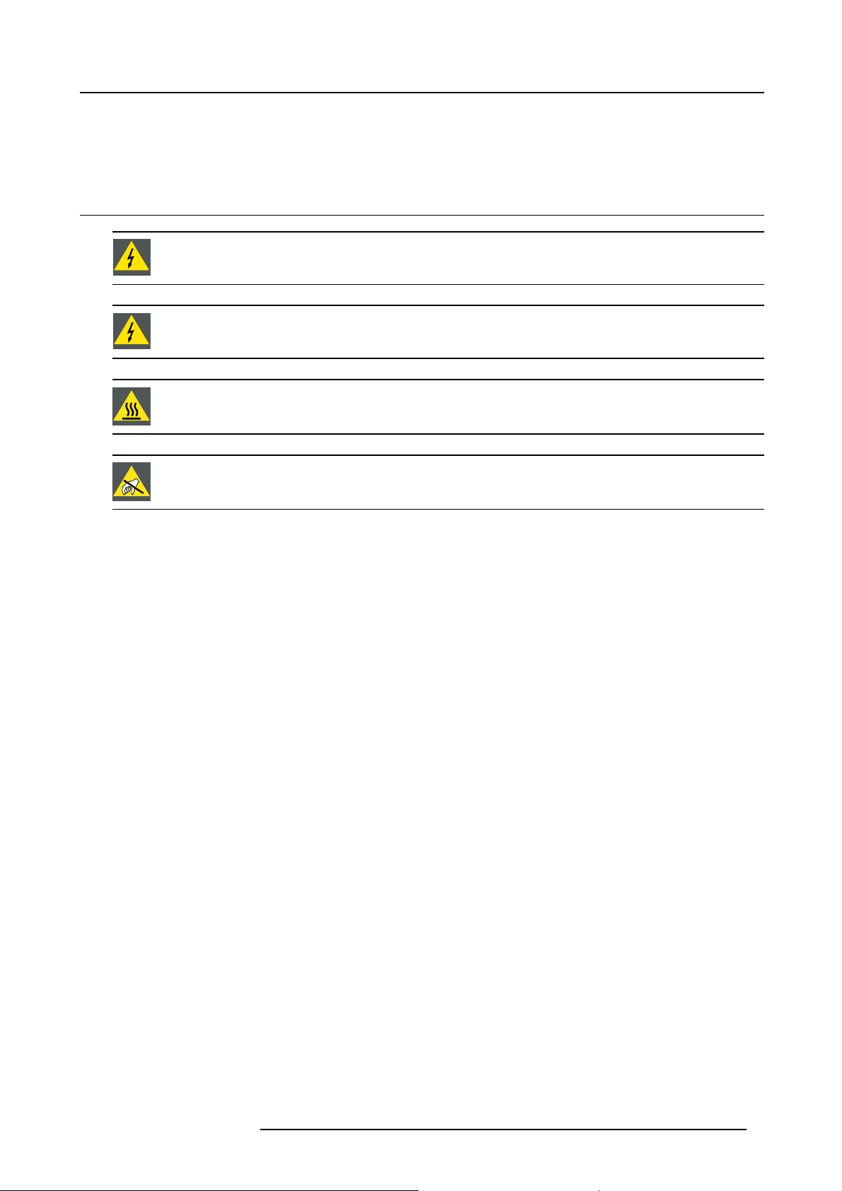
WARNING: The procedures below may only be performed by Barco trained and qualified technicians.
WARNING: Power down the projector and remove the power cord form the wall outlet before removing any
of the projector covers.
WARNING: The projector m ust be cooled down before removing any of the projector covers: wait for the co ol
down cycle to finish after switching the projector to standby (the sound of the fans comes to a very low level)
and wait for 15 mo re minutes before starting any of the procedures below.
CAUTION: Wear a wrist band which is connected to the ground while handling the electrostatic discharge
sensitive parts.
1. Safety instructions
R59770498 PMP KIT 28/02/2011 3
Page 8

1. Safety instructions
4 R59770498 PMP KIT 28/02/2011
Page 9
2. PMP KIT
2.1 Introduction
Introduction
In case of failure of a PMP, it must be replaced by a (blank) new one. However, since most of the projector related data is stored
on this board, this data will be lost while replacing the board. This includes not only key data such as Projector Device Type and
Projector Serial Number, but also the full set of factory settings of the projector which are indispensable to get a good quality image:
uniformity, colors, g ray levels, etc. Not having this factory settings will definitely result in a POOR QUALITY IMAGE.
To avoid loss of data, it isamustto make a bac kup of all the settings using the software tool Projector Support. This tool makes
it possible to make a full ba ckup, including Projector Device Type, Projector Serial Number and Runtimes and full factory settings.
When restoring the (original!) bac kup on a ( blank!) PM P, it will be fully c on figur ed in the way it was by the time of the backup.
In the situation where no backup is available and the P MP is not working properly, try to conne
and us e the Projector Support tool to make a backup. Most probably, this will be successful. If not, you will have to contact Barco.
The Projector Support tool can be found on TDE on BarcoZone ( http://kuunet.barco.com/bgs/global/TDE2/ ):
search for Software, using string “Projector Support”)
ct to the projector via Ethernet anyway
2. PMP kit
2.2 Kit description
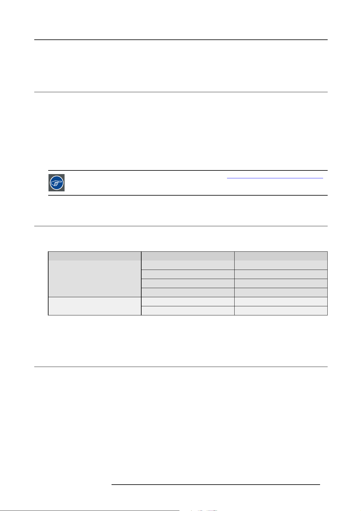
Scope
Two different kits are available. The table below points out wh
Kit number Projector type Projector article number
R7649672K
R7649676K
Galaxy NH-12
NH-12 R9010610
iD LH-12 R9010620
iCon NH-12
Galaxy NW-12
NW-12 R9010700
ich one to use.
R9040400
R9010600
R9040410
Kit content
The kit contains a blank P MP.
2.3 Kit installation (overview)
Overview of the kit installation
1. Use Pr ojector Support tool and mak
2. Replace the faulty P MP by the new one of the kit
3. Restore the backup
4. Upgrade the projector to the desired s oftware version
e a backup of the settings of the PMP to be replaced
R59770498 PMP KIT 28/02/2011
5
Page 10

2. PMP kit
6 R59770498 PMP KIT 28/02/2011
Page 11
3. Kit installation (detailed)
3. KIT INSTALLATION (DETAILED)
CAUTION: This procedure may only be performed by Barco trained and qualified technicians.
3.1 Making a backup of the PMP to be replaced
Introduction
If a PMP fails, communication via Ethernet is most probably s till possible. This implies that a ba
Projector Support tool. If there is no more communication with the faulty PMP, Barco’s helpdesk must be contacted.
How to make a backup of the PMP to be replaced?
See "Backup and restore data", page 15.
3.2 Replacing the faulty PMP
ckup can still be made using the
3.2.1 Removing the input module
Input layers 3, 4 and 5 can be installed or removed without taking out the complete input module!
The input module w ith all of the input layers can be removed as a unit!
Necessary tools
Torx screwdriver T10
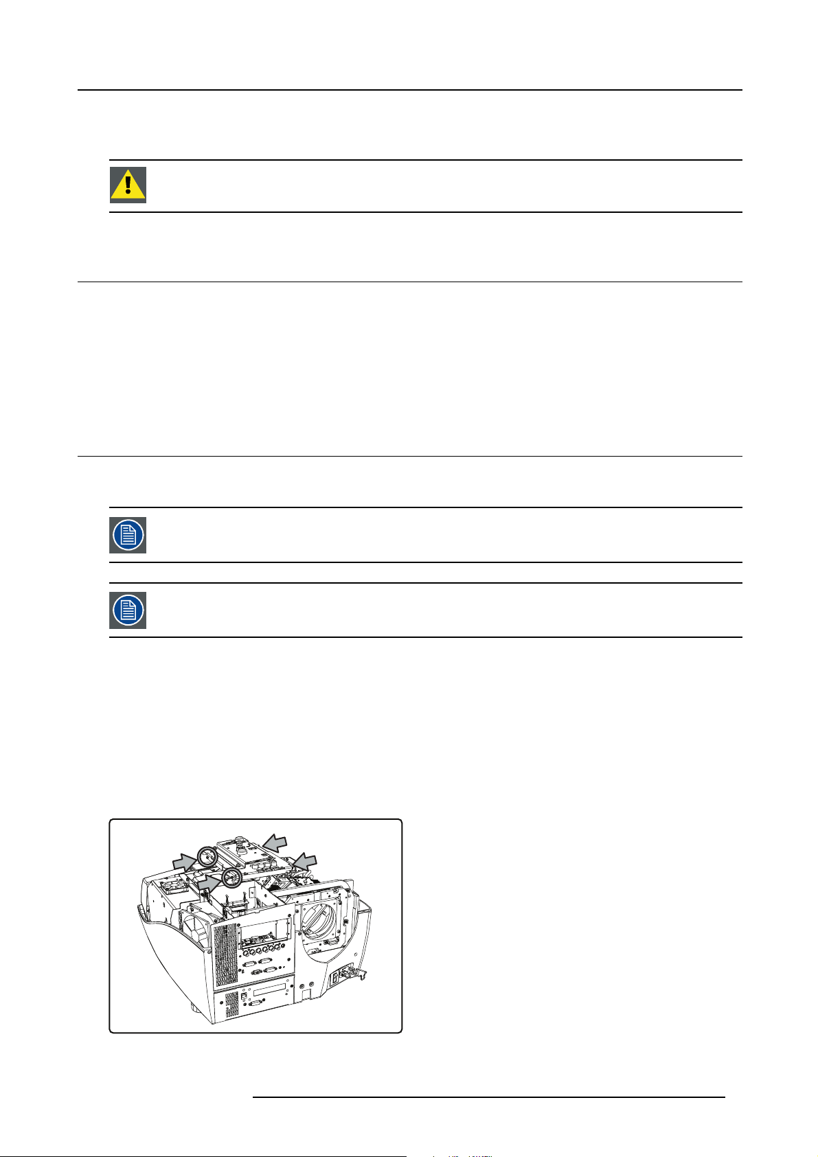
How to remove the input module?
1. Remove the covers (see concerning chapters):
- rear cover
-topcover
- engine fan cover 1
2. Remove the four screws fixing the preformatter unit to the input module
Image 3-1
Preformatter unit: fixing screws
R59770498 PMP KIT 28/02/2011 7
Page 12

3. Kit installation (detailed)
3. Lift the preformatter unit a bit and unplug the following connectors:
- J100, J101, J102 on the preformatter: data from the PMP
- J11 on the preformatter: power supply from the power box
- J410 on the PMP: commands from the local keypad
- J13 on the PMP: commands from the IR receiver
4. Remove the screw fixing the three grounding wires
5. Flip over the preformatter unit
Or,
Unplug the other connec tors on the preformatter unit and remove the unit
6. Remove both fixing s crews on the front panel of the input module
Image 3-2
Input module: fixing front screws
7. Remove the three screws fixing the input module to the chassis
Image 3-3
Input module: fixi ng screws chasis
8. Lift the input module a bit and unplug the connectors on the PMP:
- J15: power supply from the po wer box
- J19: IC2 to the desktop input
- J23; I2C from the power box
- J14: sync from the engine controller
- J22: I2C to the engine controller
- J11: ethernet wire from the front pane l
- J2 and J3 on the LVDS interface (which is mounted on the PMP): data from the d esktop input
9. Remove the input module
3.2.2 Removing the PMP
Necessary tools
Torx screwdriver T10
8
R59770498 PMP KIT 28/02/2011
Page 13

How to r emove the PMP?
1. Remove the input module (see concerning chapter)
2. Remove both screws fi xing the PMP to the front plate
Image 3-4
PMP: front fixing screws
3. Remove the side screws fixing the input boards to the PMP
3. Kit installation (detailed)
Image 3-5
4. Disconnect the PMP from the inputs by unplugging the board-to-board connectors
Image 3-6
PMP: unplug from input boards
5. Remove the LVDS conn ector from the PMP (see chapter LVDS i nterf ace )
R59770498 PMP KIT 28/02/2011
9
Page 14

3. Kit installation (detailed)
Image 3-7
PMP: fixing screws of the LVDS interface
6. Remove the screws fixing the PMP fan assembly to the PMP
Image 3-8
PMP fan assembly: fixing screws (1)
3.2.3 Installing the PMP
How to install the PMP?
1. Put t he PMP fan assembly on the PMP and fixitusing6screws
Image 3-10
PMP fan assembly: fixing screws (1)
2. Fix the LVDS interface to the PMP (see chapter LVDS interface)
Image 3-9
PMP fan assembly: fixing screws (2)
Image 3-11
PMP fan assembly: fixing screws (2)
10
R59770498 PMP KIT 28/02/2011
Page 15

Image 3-12
PMP: fixing screws of the LVDS interface
3. Connect t he PMP to the inputs by plugging in the board-to-board connectors
3. Kit installation (detailed)
Image 3-13
PMP: plug into the input board connectors
4. Fix the PMP to the input boards using the side screws
Image 3-14
PMP: side screws fixing the input boards
5. Fix the PMP to the front plate using two screws
R59770498 PMP KIT 28/02/2011
11
Page 16

3. Kit installation (detailed)
Image 3-15
PMP: front fixing screws
6. install the input module into the projector (see concerning chapter)
3.2.4 Installing the input module
Necessary tools
Torx screwdriver T10
How to install the input module?
1. Put t he connector next to its correct position and plug in the connectors:
- J15: power supply from con nector 6 on the power box
- J19: IC2 to connector J320 on the desktop input
- J23; I2C from connector 13 on the power box
- J14: sync from connector J4 on the engine controller
- J22: I2C to connector J5 on the engine co ntroller
- J11: ethernet wire from the front pane l
- J2 and J3 on the LVDS interface (which is mounted on the PMP): data from connector
2. Lower the input module until it is in its final position an d fixitusingthreefixing screws
s J200 and J300 on the desk top input
Image 3-16
Input module: fixing screw chasis
3. Fix the front plate o f the input module using
12
two screws
R59770498 PMP KIT 28/02/2011
Page 17

Image 3-17
input module: fixing front screws
4. Put the preformatter unit next to its correct position and plug in the connectors:
- J100, J101, J102 on the preformatter: data from connectors J823, J824 and J825 on the PMP
- J11on the preformatter: power supply from connector 6 on the power box
- J410 on the PMP: commands from connector J410 on the local keypad
- J13 on the PMP: commands from the IR receiver
5. Use one screw to fix the three grounding wires to the preformatter
6. Fix the preformatter unit to the input module using four screws
3. Kit installation (detailed)
Image 3-18
Preformatter unit: front screws
7. Install the covers (see concerning chapters):
- engine fan cover 1
-topcover
- rear cover
3.3 Restoring the backup
Procedure
Restore the bac kup us ing Projector Support tool. For more details, s ee "Back up and restore data", page 15.
3.4 Upgrade the projector to the desired software version
Introduction
Projector up grade is done through Ether
set to the correct values to make Ethernet comm unication po ssible between computer and projector.
R59770498 PMP KIT 28/02/2011
net. Prior to starting the procedure below, make sure the Ethernet settings in the OSD are
13
Page 18

3. Kit installation (detailed)
Necessary tools
Computer or laptop, connected to the projector through Ethernet
How to upgrade the projector s oftware?
1. Enter the correct Ethernet settings in the O SD of the projector
2. Download the desired upgrade tool to your computer or laptop
3. Run the upgr ade tool
NW- x v03.01.0001.exe
Image 3-19
Upgrade tool: example for NW-12 and Galaxy NW-12
CAUTION: Refer to the User guide to enter the Ethernet settings in the OSD of the projector
device version
14 R59770498 PMP KIT 28/02/2011
Page 19

A. Backup and restore data
A. BACKUP AND RESTORE DATA
Overview
• Connecting to the projector through Projector Support
• Making a backup of the projector’s key data
• Restoring a set of key data
About this chapter
It is extremely important to make backups of your projector data after each setting change.
This chapter describes how to use Barco’s Projector Support software tool to make a backup of the key data of a projector and how
to restore this backup.
A full backup holds the full set of data which is available on the PMP of the projec tor:
• panel settings
• projector settings
• standard/customer files
• serial number
•history
• runtimes
• option key
•etc.
Recovery of the serial number and the runtimes is possible, on condition that the processor of the target PMP does not contain this
information yet (i.e. it m ust be a new PMP).
In a (local) network where multiple PMP boards are present, only replace one PMP at a time to prevent restoring
a backup to a wrong PMP.
CAUTION: A backup fi le includes alignment data that is related to the original projector only: uploading these
files to another projector may result in bad image quality!
CAUTION: Pressing <Clear settings> in the Tools section deletes al
and factory data!
l data from the PMP, even default settings
A.1 Connecting to the projector through Projector Support
How to connect to the projector?
1. Add both the projector and the computer to the same (local) n etwork
2. Switch on the pr ojector and leave it in standby mode
3. On the computer, run the Projector Suppo rt tool
R59770498 PMP KIT 28/02/2011
15
Page 20

A. Backup and restore data
Image A-1
Projector Support tool: user interface
4. In the Communic ation Para meters section, enter the IP address or the hostname of the projector
Image A-2
Projector Support tool: enter IP address or hostname
16 R59770498 PMP KIT 28/02/2011
Page 21

A. Backup and restore data
Tip: You can also press the Query button. A list appears, showing all the pro jectors that are connected to the same network.
In this list, select the de sired projector and hit OK.
Image A-3
Projector Support tool: select Query
Image A-4
Projector Support tool: example of a query list
Special case in the Query list
If DHCP is disabled in the projector’s network settings and the fixed IP address of the projector (PMP) is not known and happens to
be outside the range of the local network, the PMP is listed in red font.
Image A-5
Projector Support tool: example of a query list
R59770498 PMP KIT 28/02/2011 17
Page 22

A. Backup and restore data
Select it and hit OK to open a new window where the network settings can be manually changed. It is advised to switch DHCP to
On to continue.
Image A-6
Projector Support tool: change DHCP setting to ON
Image A-7
Projector Support tool: confirm n etwork settings
A.2 Making a backup of the projector’s key data
How to make a backup of the projector’s key data?
It is assumed that communication with the projector has been established through Projector Support.
1. In the Backup section of
18
the Projector Support tool user interface, hit Browse
R59770498 PMP KIT 28/02/2011
Page 23

Image A-8
Projector Support tool: select browse in the Backup section
2. Select a target folder on the computer to save the backup of the projector data
A. Backup and restore data
Image A-9
Projector Support tool: browse to the backup folder
3. Change the file name (optional) and hit Save
Image A-10
Projector Support tool: change the name of the backup file (optional)
4. In the Backu p section, hit All se tti ngs
R59770498 PMP KIT 28/02/2011
19
Page 24

A. Backup and restore data
Image A-11
Projector Support tool: start the backup of all settings
5. Wait for the backup process to be finished.
Image A-12
Projector Support tool: progress bar
A successful back up is indicated by a green oval.
Image A-13
Projector Support tool: backup successful
An error is indicated by a brief des cription and a red oval. Solve the cause of the error and retry.
20
R59770498 PMP KIT 28/02/2011
Page 25

A. Backup and restore data
CAUTION: It is not allowed to do any manual change to a backup file. A changed file cannot be restored!
A.3 Restoring a set of key data
CAUTION: If a backup file has been manually changed, it will no longer be possible to restore it in the pro-
jector!
Different levels of restore
Different situations lead to different levels of r estore:
• restore data to a used PMP which already holds data and settings
• restore data to a new PMP which has no data and settings yet
When restoring to a new PMP, the Projector Support tool automatically manages the full restore. This means that the operator can
not interact. The serial number and history are restored as well.
When restoring to a used PMP, a selection of the files to be restored can be made. The Projector Support tool however manages
the files which are critical:
• serial number, runtimes, etc. will n ot be overwritten
• option keys will not be blanked or overwritten
•somefiles will be merged: newly added data (e.g. custom geometry files) will not be lost
• some settings (e.g. automatic shutdown, warning messages ON/OFF) will not be o verwritten
•etc.
How to restore the key data in a used PMP?
It is assumed that commun ication with the projector has been established through Projector Support and that an original backup file
is available ( zip format).
1. In the Restore se ction of the Projector Support tool user interface, hit Browse
Image A-14
Projector Support tool: browse to the folder with the backup file
2. Browse to the folder on the computer where the backup file is stored
3. Select the backup file and hit Open
R59770498 PMP KIT 28/02/2011
21
Page 26

A. Backup and restore data
Image A-15
Projector Support tool: browse to the backup folder
4. In the Restore section, you can select an option (not required):
- Overwrite serial number
- Overwrite device type
Image A-16
5. In the Restore section, hit A ll settings
Image A-17
Projector Support tool: start the restore of the backup
6. An overview of the files to be restored will be shown: check or uncheck the boxes according to wha t is needed and confirm with
OK
22
R59770498 PMP KIT 28/02/2011
Page 27

A. Backup and restore data
Image A-18
Projector Support tool: confirm the restor e of the backup
7. Wait for the restore process to be finished
Image A-19
Projector Support tool: progress bar
Image A-20
Projector Support tool: reboot of the PMP after the restore
A successful restore of the backup file is indicated by a gree n oval.
R59770498 PMP KIT 28/02/2011 23
Page 28

A. Backup and restore data
Image A-21
Projector Support tool: restore of the backup was successful
An error during the restore of the backup file is indicated by a brief description and a red oval. Solve the cause of the error and
retry.
24
R59770498 PMP KIT 28/02/2011
Page 29

A. Backup and restore data
Image A-22
Projector Support Tool: restore of the backup was not successful
HowtorestorethekeydatainanewPMP?
It is assumed that an original backup file is available (zip format).
1. Start the Projector Support tool and select Query in the Communication Parameters section of the user interface
2. Select the device whic h has no serial number and hit OK
R59770498 PMP KIT 28/02/2011
25
Page 30

A. Backup and restore data
Image A-23
Projector Support tool: query list
Tip: If more then one PM P without serial number is listed, the MAC address must be checked. O n the PMP board a label
mentioning the MAC address can be found near the power connector on the same s ide as the heatsinks.
3. In the Restore se ction of the Projector Support tool user interface, hit Browse
26
R59770498 PMP KIT 28/02/2011
Page 31

A. Backup and restore data
Image A-24
Projector Support tool: hit browse in the restore section
4. Browse to the folder on the computer where the backup file is stored
5. Select the backup file and hit Open
6. In the Restore section, hit A ll settings
Image A-25
Projector Support tool: browse to the backup folder
7. An overview of the files that will be restored is shown for a few s econds, but it cannot be changed
R59770498 PMP KIT 28/02/2011
27
Page 32

A. Backup and restore data
Image A-26
Projector Support tool: overview of the files that will be restored
8. Wait for the restore process to be finished
Image A-27
Projector Support tool: progress bar
Image A-28
Projector Support tool: reboot of the PMP after the restore
28 R59770498 PMP KIT 28/02/2011
Page 33

A. Backup and restore data
A successful restore of the backup file is indicated by a green oval, and the original serial number will be displayed in the Projector
identification section of the user interface.
Image A-29
An error during the restore of the backup file is indicated by a brief description and a red oval. Solve the cause of the problem
and retry.
R59770498 PMP KIT 28/02/2011
29
Page 34

A. Backup and restore data
30 R59770498 PMP KIT 28/02/2011
Page 35

INDEX
Index
B
backup 7, 15, 18
making of 18
PMP 7
D
description 5
kit 5
I
input module 7, 1 2
installing 12
removing 7
installation 5, 7
kit 5, 7
installing 1 0, 12
input module 12
PMP 10
introduction 5
K
kit 5, 7
description 5
installation 5
installation (detailed) 7
P
PMP 7–8, 10
backup 7
installing 10
replacing 7
PMP kit 5
Projector Support 15
connecting 15
R
removing 7–8
input module 7
PMP 8
replacing 7
PMP 7
restore 13, 15, 21
backup 13
S
safety 3
U
upgrade the projector 13
R59770498 PMP KIT 28/02/2011
31
 Loading...