

Page 1
Nio® medical display systems
Installation & User Manual
Supported displays: E-2620 (S), E-3620
Page 2

(This page intentionally left blank.)
(This page intentionally left blank.)
2 Nio® medical display systems
Page 3

Copyright notice
This document is copyrighted. All rights are reserved. Nor this
document, nor any part of it, may be reproduced or copied in any
form or by any means - graphical, electronic, or mechanical
including photocopying, taping or information storage and
retrieval systems - without written permission of Barco
© 2008 Barco N.V. All rights reserved.
Nio® medical display systems 3
Page 4

(This page intentionally left blank.)
4 Nio® medical display systems
Page 5

Table of Contents
Table of Contents
Preface........................................................................................ 9
Safety Instructions............................................................................. 13
Explanation of symbols..................................................................... 16
Recommendations for using your display system........................... 17
Overview................................................................................... 19
Introduction ....................................................................................... 21
BarcoMed Nio display controller overview ...................................... 23
Package contents .............................................................................. 25
Parts, controls and connectors.......................................................... 26
Installation................................................................................29
Installation precautions..................................................................... 31
Display controller installation........................................................... 32
Display installation............................................................................ 36
After unpacking the display....................................................... 36
Power connection....................................................................... 39
Video connection........................................................................ 40
USB connection........................................................................... 41
Cable routing .............................................................................. 41
Attaching the display to an arm stand............................................. 43
Windows 2000 BarcoMed Nio software installation ....................... 45
NioWatch............................................................................................ 59
Display Controller settings........................................................61
Barco Display Tab............................................................................... 63
Introduction ................................................................................ 63
Using the Barco Display Tab ...................................................... 64
BarcoMed Driver Tab ......................................................................... 66
Introduction ................................................................................ 66
Using the BarcoMed Driver Tab ................................................. 66
Nio® medical display systems 5
Page 6

Table of Contents
Status .......................................................................................... 67
Palette Mode.............................................................................. 68
Drawing Modes .......................................................................... 70
Monitor Configuration ................................................................ 71
Configuring the Windows 2000 or Windows XP desktop......... 72
Configuring the DualView desktop............................................ 72
BarcoMed Hardware Tab ................................................................... 74
Introduction ................................................................................ 74
Using The BarcoMed Hardware Tab........................................... 75
NioWatch operation.................................................................. 83
Display settings ................................................................................. 86
General ....................................................................................... 86
Display tab.................................................................................. 87
Graphic Board tab....................................................................... 89
Calibration tab ............................................................................ 90
Test patterns ...................................................................................... 95
Application settings........................................................................... 96
Calibration tab ............................................................................ 96
MediCal Administrator tab......................................................... 97
Update NioWatch............................................................................... 99
Display operation.................................................................... 101
Display operation ............................................................................ 103
Stand-by switching................................................................... 103
About the On-Screen Display (OSD)........................................ 104
Locking and unlocking user controls .......................................105
Complete OSD overview .......................................................... 107
Cleaning ..................................................................................109
Troubleshooting......................................................................113
Windows 2000 display resolution...........................................117
6 Nio® medical display systems
Page 7

Table of Contents
Configuring the Windows 2000 or Windows XP desktop....... 118
Setting the resolution of your B
Driver re-installation, updates or removal.....................................122
Reinstalling or updating your BarcoMed Nio driver ............... 122
Uninstalling the BarcoMed Nio driver or Barco NioWatch
software ..................................................................... 123
ARCOMED NIO display ............. 118
Technical Information............................................................. 127
Technical specifications................................................................... 129
Connector pin assignments............................................................. 134
Glossary............................................................................................ 135
Warranty Statement ...............................................................137
Nio® medical display systems 7
Page 8

Table of Contents
8 Nio® medical display systems
Page 9

Preface
Nio® medical display systems 9
Page 10

Preface
(This page intentionally left blank.)
(This page intentionally left blank.)
10 Nio® medical display systems
Page 11

Preface
Notice
Although every attempt has been made to achieve technical
accuracy in this document, we assume no responsibility for errors
that may be found. Our goal is to provide you with the most
accurate and usable documentation possible; if you discover
errors, please let us know.
Barco software products are the property of Barco. They are
distributed under copyright by Barco N.V. or Barco, Inc., for use
only under the specific terms of a software license agreement
between Barco N.V. or Barco Inc. and the licensee. No other use,
duplication, or disclosure of a Barco software product, in any
form, is authorized.
The specifications of Barco products are subject to change
without notice.
FCC notice
This equipment has been tested and found to comply with the
limits of a Class A digital device, pursuant to Part 15 of the FCC
rules. These limits are designed to provide reasonable protection
against harmful interference when the equipment is operated in
a commercial environment. This equipment generates, uses and
can radiate radio frequency energy and, if not installed and used
in accordance with the instruction manual, may cause harmful
interference to radio communications. Operation of this
equipment in a residential area is likely to cause harmful
interference in which case the user will be required to correct the
interference at his own expense.
Canadian notice
This Class A digital apparatus complies with Canadian ICES-003.
Cet appareil numérique de la Classe A est conforme à la norme
NMB-003 du Canada.
Nio® medical display systems 11
Page 12

Preface
Disposal Information
This product consists of devices that may contain mercury, which
must be recycled or disposed of in accordance with local, state, or
country laws. (Within this system, the backlight lamps in the
monitor display contain mercury.)
This equipment has required the extraction and use of natural
resources for its production. It may contain hazardous substances
for health and environment.
In order to avoid the dissemination of those substances in the
environment and to diminish the pressure on natural resources,
we encourage you to use the appropriate take-back systems.
Those systems will reuse or recycle most of the materials of your
end-of-life equipment in a sound way.
The crossed-out wheeled bin symbol invites you to use
those systems.
If you need more information on the collection, reuse and
recycling systems, please contact your local or regional waste
administrator.
You can also contact us for more information on the
environmental performances of our products.
12 Nio® medical display systems
Page 13
Safety Instructions
Safety Instructions
General Recommendations
Read the safety and operating instructions before operating the
display.
Retain safety and operating instructions for future reference.
Adhere to all warnings on the display and in the operating
instructions manual.
Follow all instructions for operation and use.
Electrical shock
Type of protection (electrical):
Class I equipment
Degree of safety (flammable anesthetic mixture):
Equipment not suitable for use in the presence of a flammable
anesthetic mixture with air or with oxygen or nitrous oxide.
Power connection
• Power requirements: The display must be powered using the
12 VDC power supply that is supplied with the display.
• The 12 VDC power supply must be powered by the AC mains
voltage.
Nio® medical display systems 13
Page 14

Safety Instructions
•Power cords:
Power cord with CEE 7 plug: The colors of the
mains lead are colored in accordance with the
following code: Green-and-yellow: Earth (safety
earth), Blue: Neutral, Brown: Line
Power cord with ANSI 73.11 plug: The wires of the
power cord are colored in accordance with the
following code: Green/yellow: ground, White:
neutral, Black: line (live)
• Do not overload wall outlets and extension cords as this may
result in fire or electric shock.
• Mains lead protection (U.S.: Power cord): Power cords should
be routed so that they are not likely to be walked upon or
pinched by items placed upon or against them, paying
particular attention to cords at plugs and receptacles.
Water and moisture
Never expose the display to rain or moisture.
Never use the display near water - e.g. near a bathtub,
washbasin, swimming pool, kitchen sink, laundry tub or in a wet
basement.
Ventilation
Do not cover or block the ventilation openings in the cover of the
set. When installing the display in a cupboard or another closed
location, heed the necessary space between the set and the
sides of the cupboard.
Installation
Place the display on a flat, solid and stable surface that can bear
the weight of at least 3 displays. If you use an unstable cart or
stand, the display may fall, causing serious injury to a child or
adult, and serious damage to the equipment.
More warnings in the Installation chapter.
14 Nio® medical display systems
Page 15

Safety Instructions
This apparatus conforms to:
CE, IEC 60950, UL 60950, CAN/CSA C22.2 No. 60950 (c-UL), CCC.
National Scandinavian Deviations for Cl. 1.7.2 :
Finland: "Laite on liitettävä suojamaadoituskoskettimilla
varustettuun pistorasiaan"
Norway: "Apparatet må tilkoples jordet stikkontakt"
Sweden: "Apparaten skall anslutas till jordat uttag"
Nio® medical display systems 15
Page 16
Explanation of symbols
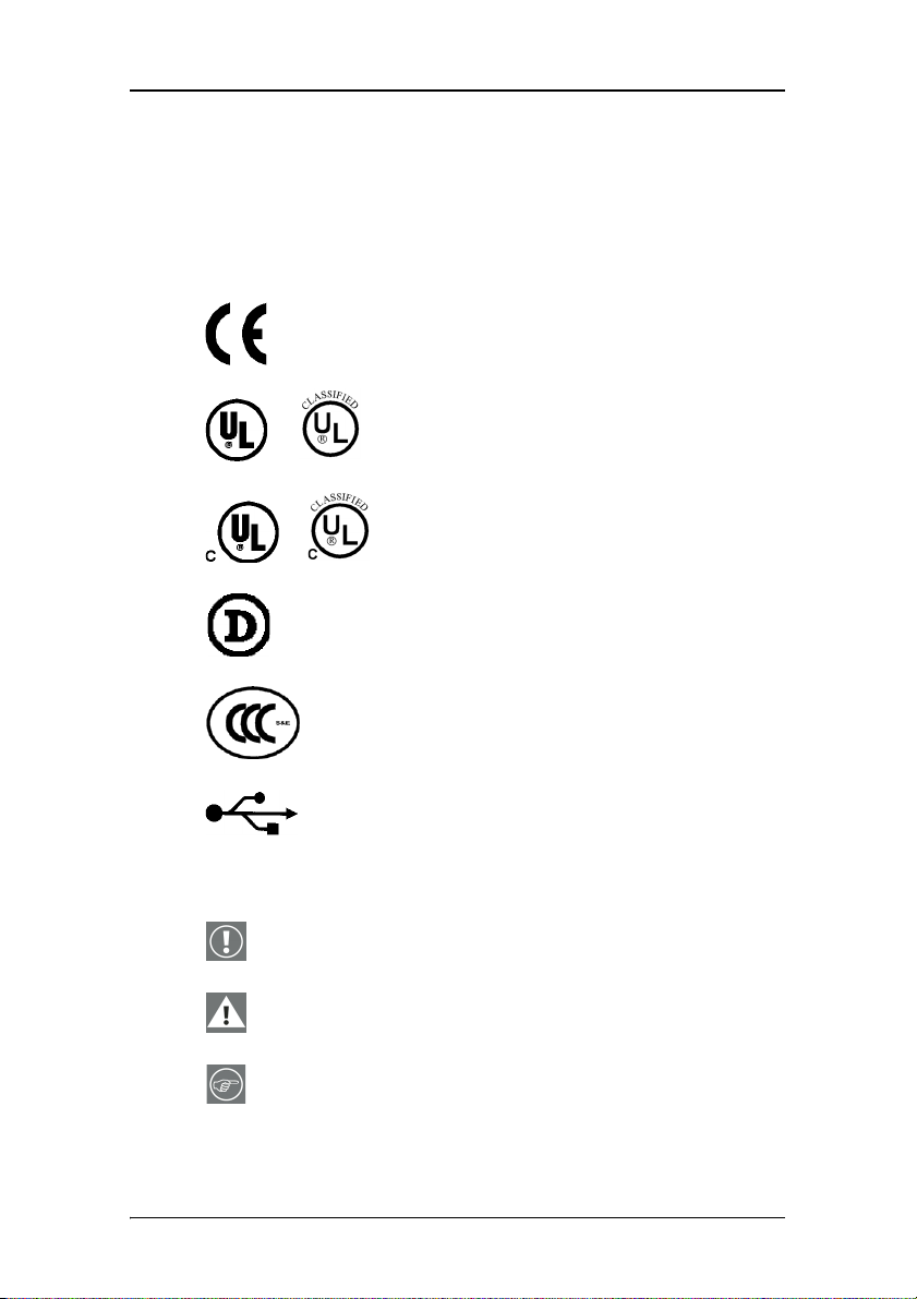
Explanation of symbols
Symbols on the display and power supply
On the display or power supply, you may find the following
symbols:
Indicates the display is approved according to
the CE regulations
Indicates the display is approved according to
the UL regulations
or
Indicates the display is approved according to
the c-UL regulations
or
Indicates the display is approved according to
the DEMKO regulations
Indicates the display is approved according to
the CCC regulations
Indicates the USB connectors on the display
Symbols used throughout the manual:
Warning or caution
Important notice or remark
Hint, tip
16 Nio® medical display systems
Page 17

Recommendations for using your display system
Recommendations for using your display system
1. Optimize the lifetime of your display
Enabling the Display Power Management System (DPMS) of your display
(in the display’s Settings menu) will optimize its diagnostic lifetime by
automatically switching off the backlight when the display is not used
for a specified period of time. By default, DPMS is enabled on your
display, but it also needs to be activated on your workstation. To do this,
go to “Power Options Properties” in the “Control Panel”.
Barco recommends setting DPMS activation after 20 minutes of
non-usage.
2. Use a screen saver to avoid image retention
Prolonged operation of an LCD with the same content on the same
screen area may result in a form of image retention.
You can avoid or significantly reduce the occurrence of this phenomenon
by using a screen saver. You can activate a screen saver in the “Display
properties” window of your workstation.
Barco recommends setting screen saver activation after 5 minutes
of non-usage. A good screen saver displays moving content.
In case you are working with the same image or an application with
static image elements for several hours continuously (so that the screen
saver is not activated), change the image content regularly to avoid
image retention of the static elements.
3. Understand pixel technology
LCD displays use technology based on pixels. As a normal tolerance in
the manufacturing of the LCD, a limited number of these pixels may
remain either dark or permanently lit, without affecting the diagnostic
performance of the product. To ensure optimal product quality, Barco
applies strict selection criteria for its LCD panels.
To learn more about LCD technology and missing pixels, consult
the dedicated white paper available at www.barcomedical.com.
Nio® medical display systems 17
Page 18

Recommendations for using your display system
4. Enhance user comfort
Every Barco multi-head display system is color matched with the highest
specification in the market.
Barco recommends keeping color-matched displays together.
Furthermore, it is important to use all displays of a multi-head
configuration at the same rate to preserve color matching
throughout the economic lifetime of the system.
5. Maximize Quality Assurance
The ‘MediCal QAWeb’ system offers online service for high-grade Quality
Assurance, providing maximum diagnostic confidence and uptime.
Learn more and sign up for the free MediCal QAWeb Essential
level at www.barcomedical.com/qa
18 Nio® medical display systems
Page 19

Overview
Nio® medical display systems 19
Page 20

Overview
(This page intentionally left blank.)
(This page intentionally left blank.)
20 Nio® medical display systems
Page 21

Introduction
Introduction
Thank you for choosing Barco.
Single display or complete system?
This manual describes installation and usage of a complete N
system. A N
IO system is a bundling of one or more displays and
IO
one or more display controllers.
However, if you have purchased the display only instead of a N
system, please refer to the chapters in this manual covering the
display, and disregard the information about the display
controller or N
IOWATCH software.
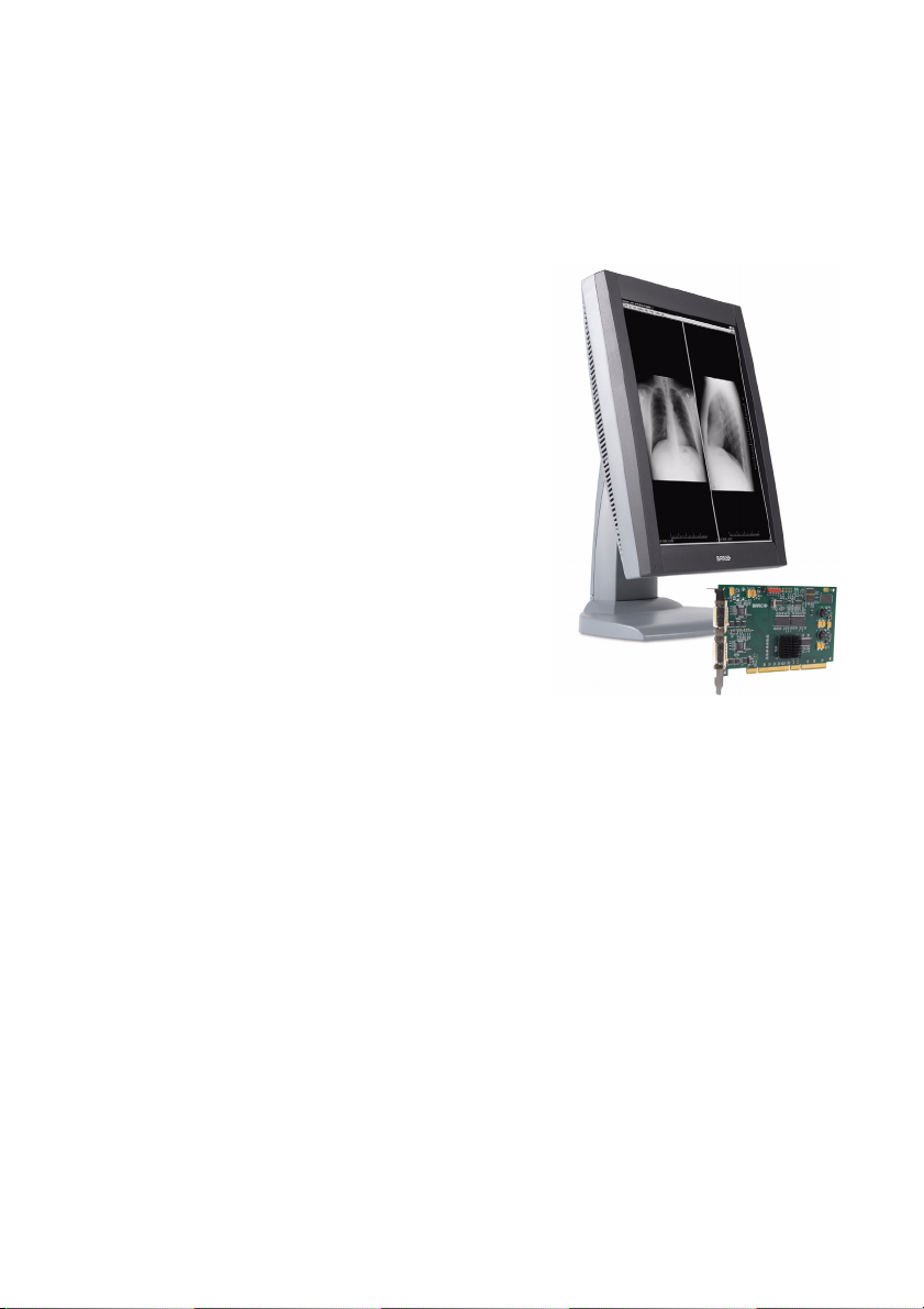
The displays
The E-2620 (S) is a 19.8-inch grayscale LCD display with a native
resolution of 1600 x 1200.
The E-3620 is a 20.8-inch grayscale LCD display with a native
resolution of 2048 x 1536.
Their high-brightness, combined with image crispness and
excellent viewing angle, makes them ideal for a multitude of
medical applications and environments.
Long-term stabilization
The displays contain a Backlight Output Stabilization system
©
(BLOS
), which continuously stabilizes the luminance output of
the LCD’s backlight. This improves the overall optical efficiency
and provides long-term image confidence.
IO
NioWatch
In N
IO systems, the display comes standard with NIOWATCH, a
user-friendly software tool that optimizes the LCD panel for
DICOM-compliant viewing.
Nio® medical display systems 21
Page 22

Introduction
Power saving
The displays are equipped with a power saving system. When left
idle for a certain time, the computer connected to the display,
will power down the display.
The power saving system can be switched on or off using the onscreen menus.
Tilt & swivel base
The versatile tilt & swivel foot allows to use the display for
viewing portrait or landscape image resolutions.
The user can easily change the panel height and viewing angle,
allowing to use the display in the optimal viewing conditions.
22 Nio® medical display systems
Page 23

BarcoMed Nio display controller overview
BarcoMed Nio display controller overview
The BarcoMed Nio Display Controller delivers a quality image
with 256 simultaneous shades of gray for medical viewing
applications.
Minimum system requirements
• Pentium II 266 MHz with 128 MB RAM (Pentium II 800MHz
with 256 MB RAM for cineloops)
• PCI slot with no obstructions
• PCI 2.1 and/or 2.2 Compliant
•Windows
Professional Service Pack 4
Features of the BarcoMed Nio display controller
• Dual Head Configuration
• 8-bit in/10-bit out LUT
• 64MB Video Memory
®
XP Professional Service Pack 1or Windows® 2000
• Portrait or Landscape Mode
• 256 Simultaneous shades of gray
• Hardware cursor
• 64bit/66Mhz Single slot PCI Card
• Displays VGA boot messages on BarcoMed Nio displays.
Supported resolutions for each head of the BarcoMed Nio display
controller
For BarcoMed Nio 2MP
• 1200 x 1600 @ 60 HZ (primary)
• 1600 x 1200 @ 60 Hz
Nio® medical display systems 23
Page 24

BarcoMed Nio display controller overview
For BarcoMed Nio 3MP
• 1536 x 2048 @ 60 HZ (primary)
• 2048 x 1536 @ 60 Hz
For BarcoMed Nio 5MP
• 2048 x 2560 @ 60 HZ (primary)
• 2560 x 2048 @ 60 Hz
For all BarcoMed Nio display controllers
The following resolution is also available when the OS is
booted in VGA mode.
• 640x480 @ Default Refresh Rate, 16 colors
System Configuration Guidelines
Because of the low power consumption and low heat generation
of the BarcoMed Nio display controller, multiple controllers may
be installed in adjacent PCI slots or adjacent to other PCI boards.
Additionally there should be no need to modify either the PC’s
power supply and/or cooling system.
24 Nio® medical display systems
Page 25

Package contents
Package contents
Nio System package
Each N
IO system contains one or more display boxes (see below)
and a system accessory box containing the following items:
• Display controller(s)
• CD-ROM with driver, NioWatch software and documentation
Display box
Each display box includes one display and a display accessory box
containing the following items:
• Plastic cover of the tilt & swivel foot
•Power supply
• Digital video (DVI) cable (25-pins)
• Two velcro strips to bind the cables
• European power cord
• American power cord
• Chinese power cord
• This manual
• Quick install card
If some of the items are missing, please contact the reseller from
whom you have purchased the unit.
Nio® medical display systems 25
Page 26
Parts, controls and connectors
BARC O
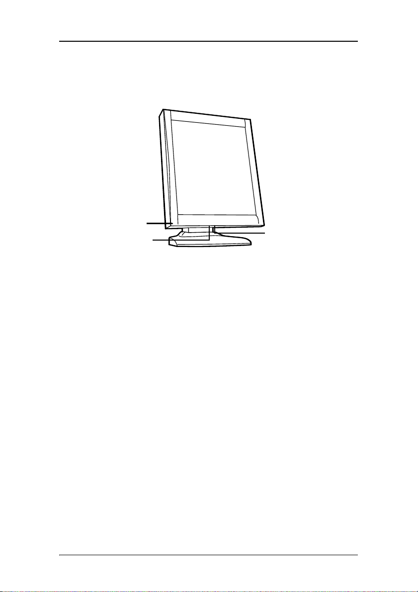
Parts, controls and connectors
Front
1
2
Figure 1: Front side
3
1. Power LED
The LED is off when the display is disconnected from the
power. The LED is also off when the LED function is disabled
in the on-screen display (OSD).
The LED is green when the display is on (when enabled in
the on-screen menus).
The LED is orange when the display is in Stand-by powersaving mode.
2. USB downstream port. See also item “6.” on page 27
3. Control wheel
The control wheel can be pressed like a push button and
rotated like a knob.
It allows to put the display in stand-by, navigate through the
on-screen display (OSD) menus and change values in the
OSD.
26 Nio® medical display systems
Page 27
Parts, controls and connectors
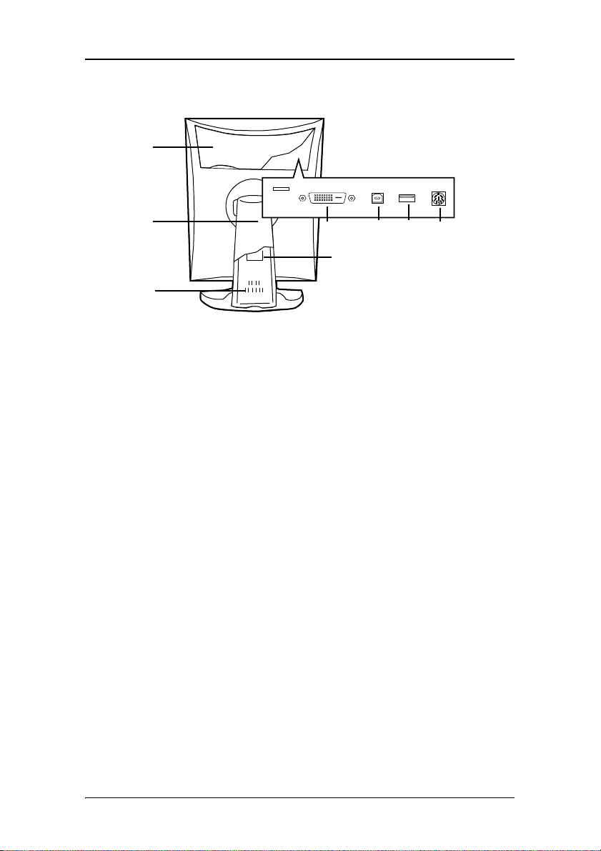
Rear
1
2
4567
8
3
Figure 2: Rear side
1. Connector compartment cover
To get access to the connectors, remove the cover by pulling
down the 2 clips at the top of the cover.
2. Tilt & swivel foot cover
This cover is packed in a separate box when the display is
shipped to the customer.
3. Tilt & swivel foot
4. DVI (digital) video input
5. USB upstream port
Connect this connector to the PC USB bus if you wish to
connect USB devices to the display’s USB downstream port.
6. USB downstream port
When the display is connected to the PC USB bus, you can
connect USB devices, such as keyboard, mouse, digital
camera, to this connector.
Nio® medical display systems 27
Page 28

Parts, controls and connectors
7. DC power input
Connect the external power supply, delivered with the
display, to this connector.
8. Tilt & swivel foot clip
The display is shipped with this clip in the foot to protect the
tilt & swivel mechanism during transport. After unpacking,
you should remove this clip.
Do not throw the clip away! Should the display have to be
packed and shipped later, the clip must be applied to the
foot again.
28 Nio® medical display systems
Page 29

Installation
Nio® medical display systems 29
Page 30

Installation
(This page intentionally left blank.)
(This page intentionally left blank.)
30 Nio® medical display systems
Page 31

Installation precautions
Installation precautions
Precautions
• Keep your original packaging. It is designed for this display
and is the ideal protection during transport.
• Avoid reflections in the flat panel to reduce eye strain.
• Place the display on a strong and stable table or desk.
• Keep the display away from heat sources and provide
enough ventilation around the display.
• Do not scratch or apply pressure to the LCD panel. This may
damage the panel permanently.
Nio® medical display systems 31
Page 32

Display controller installation
Display controller installation
Caution: Wear a grounded, protective ESD strap during
installation or handling of the display controller. Electrostatic
charges can damage the display controller.
Prior to installing your BarcoMed Nio display controller(s) in your
PC please take a few minutes to familiarize yourself with both
the display controller(s) and the PCI slots in your computer.
Figure 3: The BarcoMed Nio display controller
Using the VGA capabilities of the BarcoMed Nio display controller
Prior to installing the BarcoMed Nio controller, decide if you are
going to use its on-board VGA capabilities. If you are, check the
setting of the Jumper at J-1 on the display controller (see figure 4
on page 33). By default, VGA should be enabled, on the top two
pins.
32 Nio® medical display systems
Page 33

Display controller installation
Figure 4
If you decide to use a separate VGA monitor as your boot
monitor, you must disable the BarcoMed Nio’s on-board VGA
capabilities by moving the jumper to the bottom two pins.
Caution: To use multiple BarcoMed Nio controllers in a single host
with VGA enabled, you should enable VGA on only ONE of the
BarcoMed Nio display controllers and disable VGA on ALL the
other BarcoMed Nio display controllers.
Examples of PCI slots
Although the BarcoMed Nio is a 64-bit board, it may be installed
in either a 64-bit or 32-bit PCI slot. However, installing it in a
32-bit PCI slot will result in a decrease in performance. Figure
figure 5 on page 34 illustrates the types of slots so that you can
correctly identify which one to use for the BarcoMed Nio.
Nio® medical display systems 33
Page 34

Display controller installation
Figure 5: PCI and RAID Controller Slots
Installing the BarcoMed Nio display controller
Install the BarcoMed Nio controller in your computer following
these steps:
1. Turn off the power to your computer and disconnect the
power cord, however make sure that the computer chassis is
still grounded
2. Remove the chassis cover according to the manufacturer’s
instructions. Be sure to observe safety warnings.
.
3. If you have decided to use the on-board VGA capabilities of
the BarcoMed Nio (see Using the VGA capabilities of the
BarcoMed Nio display controller on page 32), you must
now remove any VGA display controller(s) that are currently
installed in the computer or disable any VGA controllers that
are integrated into your PC’s motherboard.
4. Install the BarcoMed Nio display controller into a free PCI
slot, either 64-bit or 32-bit (see 5 above, for examples of
slots). Be sure that the display controller is seated firmly in
the slot.
5. Secure the card to the chassis with the PC’s I/O panel
mounting screw, and replace the chassis cover.
34 Nio® medical display systems
Page 35

Display controller installation
6. Connect the primary display to the connector marked “VID 1”
on the BarcoMed Nio display controller using the provided
DVI cable (see 6 below). For a dual-headed BarcoMed Nio
setup, connect the secondary display to the other connector
on the display controller.
7. Reconnect the power cord, turn on the power, and boot the
system as usual.
Running multiple BarcoMed Nio Display Controllers in a single host
The physical order of the displays may vary when you are
running multiple BarcoMed Nio display controllers. This is due to
the PC’s PCI bus control in the system BIOS, and not the
BarcoMed display controller. It may become necessary,
depending on how your PC’s BIOS configures the PCI bus, to
switch your DVI display connections to achieve a linear desktop
configuration.
Figure 6
Nio® medical display systems 35
Page 36

Display installation
Display installation
After unpacking the display
Important:
In the factory, the height-positioning system in the display foot is
blocked with a red clip to prevent damage during transportation.
Before installing the display, you must remove this clip.
Clip
Figure 7
To remove the clip:
1. Position the display with its rear side facing you.
2. Pull the red clip out of the fixation holes in the foot.
3. Keep the clip in case the display needs to be shipped later.
36 Nio® medical display systems
Page 37

Display installation
BARCO
BARCO
Adjust the panel orientation
You can change the orientation of the panel at any time, but it is
more convenient to select landscape or portrait orientation
before connecting the cables.
Figure 8:
Portrait
orientation
Figure 9:
Landscape
orientation
To change the panel orientation:
1. Stand at the front side of the panel and take the panel at
both sides.
2. Very important: Tilt the panel before changing the
orientation.
Should you change the panel orientation without tilting it
first, you might irreversibly damage the tilt & swivel
mechanism.
Nio® medical display systems 37
Page 38

Display installation
BARC O
Figure 10: Tilt the panel before rotating
3. To change from portrait to landscape, turn the panel
counterclockwise.
Figure 11: To rotate the panel from portrait to landscape
4. To change from landscape to portrait, turn clockwise.
Notice:
If, after installing the display or the system, you change the panel
orientation while an image is on the screen, the result depends
on your application:
38 Nio® medical display systems
Page 39

Display installation
•In a complete NIO system, the image orientation will adapt
to the new panel orientation automatically after a second.
• If you would use the display without the N
controller board, the image orientation will not change with
the panel orientation.
To change the orientation of the image, you will have to
change the resolution in the Windows Display control panel
(if possible).
Power connection
To connect the power:
IO display
(2)
Figure 12
(2)
(3)
Figure 13
1. To get access to the connectors, remove the connector
compartment cover by pulling down the 2 clips at the top of
the cover.
Nio® medical display systems 39
Page 40

Display installation
2. Connect the output of the 12V DC power supply to the DC
input of the display.
3. Connect one end of the proper power cable to the AC input
of the 12V DC power supply.
4. Connect the other end of the power cord to a grounded
power outlet.
Video connection
Connecting DVI cables: One display:
(1)
Figure 14
1. Connect one end of the DVI cable to the DVI input of the
display.
2. Connect the other end of the DVI cable to the DVI connector
of the display controller board. If this board has 2 video
heads (2 video outputs), connect to output Vid 1 (Head A).
Connecting DVI cables: Two displays:
1. Connect the left display (when looking at the front side) to
display controller output Vid 1 (Head A) as described above.
2. Connect the second display to output Vid 2 (Head B).
40 Nio® medical display systems
Page 41

Display installation
USB connection
The USB connection allows you to use the display as USB hub, to
which you can connect USB devices, such as a keyboard, mouse
or digital camera.
To connect the USB cable:
(1)
(2)
Figure 15
1. Connect a PC USB downstream connector to the display’s USB
upstream connector by means of a USB cable.
2. Connect any USB device to one of the display’s USB
downstream connectors.
Cable routing
Routing the signal cables
• Bind the cables in the connector compartment together with
the cable tie inside the connector compartment.
• Put the connector compartment cover back on the display.
Pay attention that the signal cables are positioned under the
bulge in the cover.
• Push the cables into the clips on the rear of the tilt & swivel
foot.
Nio® medical display systems 41
Page 42

Display installation
• Bind the cables together above and under the foot, by
means of the 2 velcro strips attached to the inside of the foot
cover (packed inside the accessory box).
• At last, put the foot cover back in place.
To put the foot cover in place:
(1)
Figure 16
1. Push the upper side of the cover onto the foot, so that the
hooks inside the cover are positioned right under the bulges
at the rear of the foot.
2. Slide the cover upward while moving the lower side of the
cover towards the foot.
3. Press the cover to the foot so that it makes a clicking sound.
42 Nio® medical display systems
Page 43

Attaching the display to an arm stand
Attaching the display to an arm stand
The panel, standard attached to the tilt & swivel foot, is
compatible with the VESA 100 mm standard. So it can be used
with an arm stand according to the VESA 100 mm standard.
Therefore, the tilt & swivel foot must be removed from the panel.
Important:
• Use an arm that is approved by VESA (according to the VESA
100 mm standard).
• Use an arm that can support a weight of at least 13 kg
(28.66 lbs).
To attach the display to an arm stand:
1. Put the display face down on a clean surface. Be careful not
to damage the panel screen.
2. Remove the tilt & swivel foot cover.
3. Remove the small screw (A) fixing the small plastic cover on
top of the foot. Next, remove the small cover itself.
B
A
Figure 17: Display with tilt & swivel foot cover removed
4. Unscrew the 2 screws fixing the round plastic cover (B).
5. Lift up the round plastic cover.
Nio® medical display systems 43
Page 44

Attaching the display to an arm stand
6. Remove the four screws fixing the foot while supporting the
foot.
7. Attach the arm stand firmly to the panel using 4 screws M4
x 8 mm.
4 screws M4 x 8mm
Figure 18
44 Nio® medical display systems
Page 45

Windows 2000 BarcoMed Nio software installation
Windows 2000 BarcoMed Nio software installation
Note: These instructions apply to both Windows®2000 and
Windows
®
XP.
Preparation
Prior to installing your BARCOMED NIO software the following
should be done.
1. Install the BarcoMed Nio display controller(s) in your system.
2. Connect the B
BarcoMed Nio display controller(s) and power supply(s).
3. Decide if you want to install the NioWatch Software in
addition to the driver.
4. Decide if you are going to install the BarcoMed Nio driver
with DualView enabled or disabled) (see Step “7.” on
page 50 for a description of DualView).
5. Decide which Palette Mode you wish to use with the
BarcoMed Nio display controller. If you are uncertain, use the
default setting as this setting can be changed later using the
BarcoMed Driver Tab of the Windows Display Properties
control panel.
6. Put the BarcoMed Nio 2MP display panel in landscape
position before installing the software. Put the BarcoMed Nio
3MP/5MP display panel in portrait position before installing
the software. If you wish to change the panel orientation
later, the image orientation will adapt automatically to the
panel orientation after rebooting the PC.
ARCOMED NIO display panel(s) to the
Note: Both displays connected to a single display controller
must have the same physical orientation and resolution in
order to be attached to the Windows desktop.
Nio® medical display systems 45
Page 46

Windows 2000 BarcoMed Nio software installation
Using the BarcoMed product installation wizard
To install your BarcoMed Nio Windows display controller driver
and NioWatch Software for the first time follow the steps below.
If you are reinstalling the drivers or installing a new driver
release over an existing driver release skip to the step 5:
1. Boot your system, and log in using an account with
administrator privileges.
2. For each BarcoMed Nio display controller installed in your
system Windows will launch the “Found New Hardware
Wizard”. Click “Cancel”. Continue to click “Cancel” until
Windows stops launching the “Found New Hardware
Wizard”. Please be patient as this may take several minutes
while Windows scans its library of Plug-and-Play device
drivers to see if it has a driver for your BarcoMed Nio
controller.
3. If Windows advises you that it has finished installing all the
new devices in your system and that you must reboot your
system in order for the changes to take effect, click “No”.
4. Insert your BarcoMed Nio Software CD into your computer’s
CD drive. If the “BarcoMed Product Installation Wizard”
doesn’t start within one minute, browse the contents of your
BarcoMed Nio Software CD and double click on the file:
“Setup.exe” to start the wizard.
The BarcoMed Product Installation Wizard will begin by
inspecting your system to make certain that all of the
Windows components it needs are up to date. If they are, the
BarcoMed Product Installation Wizard will display the
BarcoMed Product Installation Wizard’s welcome screen (see
19 on page 47). If the screen shown in figure 19 appears,
please skip to step “5.” on page 48, otherwise continue to
the next page.
46 Nio® medical display systems
Page 47

Windows 2000 BarcoMed Nio software installation
Figure 19
If it determines that the Microsoft Installer is either out of
date or missing, it will display the screen shown in figure 20
below. Click “OK” to continue, the wizard will then install a
newer version of the Microsoft Installer.
Figure 20
The BarcoMed Product Installation Wizard will advise you
when it has successfully installed the new version of the
Microsoft Installer. Click “OK”.
The Wizard may prompt you to restart your system. If it does,
click “Yes” to restart your system now.
When your system restarts log in using an account with
administrator privileges. Windows will again launch the
“Found New Hardware Wizard” for each BarcoMed Nio it
finds in your system. Click “Cancel”. Continue to click
“Cancel” until Windows stops launching the “Found New
Nio® medical display systems 47
Page 48

Windows 2000 BarcoMed Nio software installation
Hardware Wizard - Video Controller”. Again, please be
patient as Windows will again scan its library of Plug-andPlay device drivers to see if it has a driver for your
BarcoMed Nio controller.
The BarcoMed Software Install Wizard will automatically
restart and the BarcoMed Product Installation Wizard’s
welcome screen will again be displayed (figure 21 below).
5. By default all the software on the BarcoMed Software CD will
be selected. For the initial installation we recommend that
you install all of the software. If you do not want to install a
particular BarcoMed Software product at this time, deselect it
by clearing the checkbox next to it. Click “Install” to
continue or “Cancel” to exit the wizard.
Figure 21
Driver installation
6. Click “Next” on the Display Driver Wizard’s Welcome Screen
to continue or “Cancel” to exit the Display Driver Wizard and
return to the Software Install Wizard.
The Device Selection Screen’s dialog box (figure 22 on
page 49) should show only those devices physically installed
and supported by the BarcoMed display controller driver on
48 Nio® medical display systems
Page 49

Windows 2000 BarcoMed Nio software installation
your BarcoMed Software CD. Select the device you want to
install and then click “Next”.
Note: If there are no BarcoMed devices installed, or if
Windows does not recognize the installed devices, or if the
driver on your BarcoMed Software CD does not support the
installed devices, the dialog box will be empty
BarcoMed driver wizard will exit when you click “Finish” or
“Cancel”.
1
, and the
Figure 22: Sample device selection screen, the device shown in
your system may be different.
Caution: You can install the driver for only one type of
BarcoMed device at a time. If you have multiple types of
BarcoMed devices installed in your computer, you will need
to rerun the installer to install the drivers for the other
devices.
If you select a device with an installed driver, the wizard will
warn you if the installed driver is newer than the one you
are installing (see figure 23 on page 50).
1. If Windows does not recognize the installed BarcoMed device, special settings
may need to be made in the BIOS to support non-AGP video controllers or to
support multiple video controllers. Check with your PC manufacturer.
Nio® medical display systems 49
Page 50

Windows 2000 BarcoMed Nio software installation
Figure 23
Click “OK” to install the new driver. If you don’t want to
replace the exiting driver, click “OK” and then click
“Cancel”.
7. Your selection on the "Enable DualView" screen (figure 24
below) determines if DualView is enabled or not. DualView
allows a dual head display controller to display two separate
desktops, one for each display instead of a single virtual
desktop that spans across both displays.
Figure 24
The difference between running with DualView enabled or
disabled is shown in figures 25 and 26 on page 51. If you
wish to enable DualView “check” the checkbox next to
"Enable the DualView device?", and click "Next". If you do
not wish to enable DualView “clear” the checkbox next to
"Enable the DualView device?", and click "Next" to continue.
50 Nio® medical display systems
Page 51

Windows 2000 BarcoMed Nio software installation
Figure 25: DualView Disabled–Rectangle 2 represents the combined
heads of the BarcoMed Controller.
Figure 26: DualView Enabled–Rectangles 2 & 3 represents the
individual heads of the BarcoMed Controller.
Special Note: If you installed the drivers with DualView
disabled, Windows will still show two devices installed for
each BarcoMed Display Controller installed under "Display
Nio® medical display systems 51
Page 52

Windows 2000 BarcoMed Nio software installation
Adapters" in the "Device Manager Control Panel". The second
device will be disabled. This is normal. Do NOT try to enable
any of the disabled display adapters.
8. The “Device Confirmation” screen displays the device driver
that will be installed and if DualView will be enabled or not.
If you want to change your selection, click “Back” to return
to the Device Selection Screen. Click “Next” to begin
installing the driver. Click “Cancel” to abort the driver
installation.
Caution: Once you click “Next”, you cannot cancel the driver
installation.
Prior to beginning the installation the BarcoMed Driver Install
Wizard will warn you that while the driver is being installed
your display may flicker. Click “OK” to continue.
9. When the screen shown in figure 27 below and figure 28 on
page 53 appears, click “Yes” or “Continue Anyway” to
continue. This screen may appear multiple times.
Figure 27: Windows 2000 Digital Signature Not Found Warning
52 Nio® medical display systems
Page 53

Windows 2000 BarcoMed Nio software installation
Figure 28: Windows XP Windows Logo Testing Warning
10. When the screen shown in figure 29 below appears select
the palette mode which is the correct one for your viewing
application. If you are uncertain use the default settings. You
can change the palette mode later (See “Palette Mode” on
page 68 of the BarcoMed Driver Tab section). If you want to
enable DirectDraw check the checkbox next to “Enable
Direct Draw”.
Nio® medical display systems 53
Page 54

Windows 2000 BarcoMed Nio software installation
Figure 29
When the Driver Install Wizard tells you that it has
successfully installed the selected driver, click “Finish”.
The wizard will now begin installing the next selected piece
of BarcoMed Software. If you are working with the default
selections, this will be the Barco NioWatch. Please turn to the
section, “BarcoMed NioWatch installationBarco DPMS
Screen Saver installation” below.
If the installation of the products you selected at the
beginning is complete, click “Finish” to exit the BarcoMed
Product Install Wizard or click “Back” to return to the
Welcome Screen of the BarcoMed Product Install Wizard to
select additional software to install. When you click “Finish”
Windows may prompt you to restart your system, if it does
click “Yes”. When your system restarts, boot normally and
log in using an account with administrator privileges and
turn to the section “Barco monitor plug and play
software” on page 56.
Note: Clicking “Cancel” will also return you to the BarcoMed
Product Install Wizard, but will not delete the Barco display
54 Nio® medical display systems
Page 55

Windows 2000 BarcoMed Nio software installation
driver. The wizard will also begin to install the next selected
piece of BarcoMed Software.
If the Wizard failed to successfully install the selected driver,
it will warn you that the installation failed. Click “Finish” to
return to the BarcoMed Product Install Wizard. The wizard
will now begin installing the next selected piece of
BarcoMed Software. Click “Cancel”, then click “Yes” then
click “Finish”. Now “Back” and try reinstalling the driver
following the steps above or using the steps outlined in the
section “Reinstalling or updating your BarcoMed Nio
driver” on page 122.
BarcoMed NioWatch installation
1. Click “Next” on the Welcome Screen of the BARCO NioWatch
InstallShield Wizard (figure 30 on page 55) to begin the
installation or click “Cancel” to cancel and return to the
BarcoMed Product Install Wizard.
2. After reading the Software License Agreement on the next
screen, click ”Yes“ to continue.
3. Click “Next” on the Choose Destination Location screen to
install the NioWatch software in the default location. Or click
“Browse” to install the software in a different location.
Figure 30
Nio® medical display systems 55
Page 56

Windows 2000 BarcoMed Nio software installation
4. Click “Next” on the Select Program Folder screen to install
the NioWatch software in the default location. Or select one
of the folders in the Existing Folders dialog window.
While the wizard is installing NioWatch, it will display a
Setup Status screen.
5. When the Wizard has finished installing the NioWatch
software it will ask you if you want to read the Release Notes
now. Click “Yes” or “No” to continue.
6. When the InstallShield Wizard Complete Screen appears click
“Finish”.
7. Click “Finish” on the BarcoMed Product Installation screen to
complete the install process.
If the installation of the products you selected at the beginning is
complete, click “Finish” to exit the BarcoMed Product Install
Wizard or click “Back” to return to the Welcome Screen of the
BarcoMed Product Install Wizard to select additional software to
install. When you click “Finish” Windows may prompt you to
restart your system, if it does click “Yes”.
When your system restarts, boot normally and log in using an
account with administrator privileges and turn to the section
“Barco monitor plug and play software” on page 56.
Barco monitor plug and play software
After your system restarts and you have logged in, Windows will
install the Barco Monitor Plug-n-Play software. If Windows
displays the screens shown in figure 31 below and figure 32 on
page 57, click “Yes” or “Continue Anyway” to continue.
56 Nio® medical display systems
Page 57

Windows 2000 BarcoMed Nio software installation
Figure 31: Windows 2000 Digital Signature Not Found Warning
Figure 32: Windows XP Windows Logo Testing Warning
The Barco Monitor Plug and Play software should automatically
set the resolution for the displays of your BarcoMed Nio System.
It may be necessary to reboot the system a second time if the
window on the Barco display is not running in the same
orientation as the display. For example the display is in portrait
orientation, but the window appears in landscape orientation.
However, the second head of a dual headed system may be
inactive. To make this display active you must extend your
desktop to these displays using the “Windows Display Control
Nio® medical display systems 57
Page 58

Windows 2000 BarcoMed Nio software installation
Panel”. If for some reason Windows failed to correctly set the
resolution of your displays please turn to the section “Setting
the resolution of your B
the Troubleshooting Section of this manual for instructions on
setting the resolution.
ARCOMED NIO display” on page 118 of
58 Nio® medical display systems
Page 59

NioWatch
NioWatch
BarcoMed NioWatch installation
1. Click “Next” on the Welcome Screen of the BARCO NioWatch
InstallShield Wizard (figure figure 33 on page 59) to begin
the installation or click “Cancel” to cancel and return to the
BarcoMed Product Install Wizard.
2. After reading the Software License Agreement on the next
screen, click “Yes” to continue.
3. Click “Next” on the Choose Destination Location screen to
install the NioWatch software in the default location. Or click
“Browse” to install the software in a different location.
Figure 33
4. Click “Next” on the Select Program Folder screen to install
the NioWatch software in the default location. Or select one
of the folders in the Existing Folders dialog window.
While the wizard is installing NioWatch, it will display a
Setup Status screen.
5. When the Wizard has finished installing the NioWatch
software it will ask you if you want to read the Release Notes
now. Click “Yes” or “No” to continue.
Nio® medical display systems 59
Page 60

NioWatch
6. When the InstallShield Wizard Complete Screen appears click
“Finish”.
7. Click “Finish” on the BarcoMed Product Installation screen to
complete the install process.
Note: Silent mode installation
You can install NioWatch in silent mode on a system where no
previous version of NioWatch is installed.
Silent mode means that no user intervention is required during
installation.
To install NioWatch in silent mode:
1. Open the command prompt (DOS window) in Windows.
2. Using DOS commands, navigate to the folder containing the
NioWatch setup.exe file on the CD-ROM.
3. Type: “setup.exe_/s_/v/qn” (where “_” represents a space)
60 Nio® medical display systems
Page 61

Display Controller settings
Nio® medical display systems 61
Page 62

Display Controller settings
(This page intentionally left blank.)
(This page intentionally left blank.)
62 Nio® medical display systems
Page 63

Barco Display Tab
Barco Display Tab
Introduction
The Barco Display Tab is used for gathering information about the
BarcoMed Flat Panel Display(s).
To access the Barco Display Tab do the following:
1. Open the “Display Properties Control Panel” by right clicking
on the desktop, then select “Properties”.
2. Under Windows 2000 and Windows XP, click on the
“Settings” tab. Double click on the rectangle that
represents the BarcoMed Display you are working with to
bring up its properties page. Click on the “BARCO Display”
tab (figure 34 below).
Figure 34: BARCO Display Tab under Windows 2000 and
Windows XP
Nio® medical display systems 63
Page 64

Barco Display Tab
Using the Barco Display Tab
Displays
All of the available display adapters that are of the same type as
the current barco display adapter are shown here graphically,
with one display icon representing each port of a display adapter.
The icon orientation reflects the display resolution. Only those
ports with a display attached to them are active. If an icon is
grayed out, that indicates a port with no head attached to it.
When running DualView under Windows 2000 and Windows XP
the desktop must be extended to include each display, otherwise
those ports will not be visible to the Barco Display Tab.
Hovering the cursor over a display icon will pop up a window
with information that identifies the display.
Properties
You may access the Properties page of the currently selected
display, which is represented by the monitor icon above with the
black frame around it, by either clicking on the “Properties”
button or double clicking on the icon.
BarcoMFD library
This is the version of the barcomfd library currently used. This
library provides APIs for interacting with the displays.
Nio Display Properties
You may access the Properties page of the currently selected
display, which is represented by the monitor icon above with the
black frame around it, by either clicking on the “Properties”
button or double clicking on the icon. This screen (figure 35 on
page 65) shows properties of the currently active display.
Name: Displays the model name of the display.
Serial Number: Displays the serial number of the display.
64 Nio® medical display systems
Page 65

Barco Display Tab
Backlight RunTime: This is time in hours that the back light has
been on. A common question is: How much longer will the
backlight last? The backlight will typically last a very long time,
but will only be able to hold a calibrated output of for 17000
hours, after which time it will become slowly dimmer. For
displays calibrated at, an estimate of how long it will be before a
backlight replacement is needed = 17000 hours – backlight age.
Firmware Revisions: This is the runtime firmware that is loaded
in the display. This information may be helpful when there is a
problem.
Internal Temperature: This is the temperature inside the display.
It starts out at about the ambient temperature when the display
backlight is first turned on, then rises slowly to a steady-state
temperature as the display warms up. Changes in light level due
to temperature variations are completely controlled by the IGuard sensor on the front of the display.
Current Luminance Value: This is the current luminance value of
the display. It may vary a bit from time to time, for the display
continuously calibrates itself to meet the target luminance value.
Figure 35
Nio® medical display systems 65
Page 66

BarcoMed Driver Tab
BarcoMed Driver Tab
Introduction
After the BarcoMed Windows display controller driver is installed,
a new Display Properties tab is available for configuring special
features of the BarcoMed display controller.
Languages supported
The BarcoMed Driver Tab supports the following languages:
English (U.S) (default)
Dutch
German
Korean
Japanese
Simplified Chinese
Traditional Chinese
To change between the languages select the correct region via
the Regional Settings Control Panel in your machine’s Start >
Settings > Control Panel.
Using the BarcoMed Driver Tab
Please note that you must have logged on to Windows using an
account with administrator privileges in order to use the
BarcoMed Tabs of the Windows Display Control Panel to change
any display settings.
1. Open the “Display Properties Control Panel” by right clicking
on the desktop, then select “Properties”.
2. Under Windows 2000 or Windows XP, click on “Settings”
tab. Double click on the rectangle that represents the Barco
display whose settings you wish to change to bring up its
property page. Click on the “BarcoMed Driver” tab (see
figure 36 on page 67).
66 Nio® medical display systems
Page 67

BarcoMed Driver Tab
Figure 36: BarcoMed Driver Tab under Windows 2000 and
Windows XP
Status
The Status section displays information about the current
BarcoMed display controller, driver, and the currently selected
display resolution.
Graphics Board
This displays the current BarcoMed display controller.
Driver Version
This displays the current BarcoMed driver version.
Nio® medical display systems 67
Page 68

BarcoMed Driver Tab
Resolution
This displays the currently selected display resolution.
Palette Mode
In the Palette Mode section you can choose one of the four
following Palette Modes.If you are using a color display in
conjunction with your Barco grayscale display(s) under Windows
2000 or Windows XP, prior to selecting a palette mode please
make certain that you have configured your Window 2000 or
Windows XP desktop correctly. (See the section “Configuring the
Windows 2000 or Windows XP desktop” on page 72.)
Color to Gray Compatibility
Use this palette option for applications, such as Java, which
require True Color support. Such applications may not work
correctly when using one of Barco's three "Standard 8-bit (256color)" palette modes. All applications that are designed to work
correctly with 8-bit (256-color) modes should continue to work
normally.
Please note that dithering is not used while in this mode. The
Enable Dithering check box will be grayed-out, and dithering will
be automatically disabled regardless of whether this check box is
checked. This complies with the Windows standard interface
method.
Also, please note that direct access to the hardware through
DirectDraw is not allowed in this mode. The Enable DirectDraw
check box will be grayed-out, and DirectDraw’s access to the
hardware will be automatically disabled regardless of whether
this check box is checked. DirectDraw is still usable through
DirectDraw’s Hardware Emulation Layer.
UserModifiable Color Palette
This option allows applications to modify the palette contents
dynamically. As indicated in figure 37 on page 69, this mode
reserves the first 10 and last 10 entries in the palette for the
68 Nio® medical display systems
Page 69

BarcoMed Driver Tab
Windows operating system, but applications can manipulate the
middle 236 entries. This is the standard palette mode as
configured by Windows.
Figure 37
Static Gray Palette including standard system colors
This option sets the palette to be a static set of 256 gray values.
Therefore, applications are denied the ability to dynamically
change or allocate palette entries. This prevents palette conflicts
between applications, which can cause image color values to
appear distorted in the background application.
As shown in figure 38, the 20 standard system colors are
converted from RGB to gray values. The rest of the 236 entries
from index 10 to 245 contain the missing gray values so that the
palette has the full 256 gray values within it.
Figure 38
Please note that dithering is not permitted while in this mode.
The Enable Dithering check box will be grayed-out, and dithering
will be automatically disabled regardless of whether this check
box is checked. This complies with the Windows standard
interface method. If you are unsure whether or not your
application requires this “Static Gray Palette including Standard
System Colors” mode, contact your application provider.
Nio® medical display systems 69
Page 70

BarcoMed Driver Tab
Static Gray Palette with NO system colors
This option sets the palette to be a static linear ramp of 256
shades of gray. Therefore, applications are denied the ability to
dynamically change or allocate palette entries. This prevents
palette conflicts between applications, which can cause image
color values to appear distorted in the background application.
As shown in figure 39, each of the 256 entries in the palette has
an RGB value of (i, i, i) where i is the index from 0 to 255.
Figure 39
If you wish to use a static gray palette we recommend using the
“Static Gray Palette including Standard System Colors” option
instead of this one. This is due to the fact that some applications
assume that the first and last 10 entries of the palette are the
standard system colors. In this palette mode, these entries are
made up from entries in the bottom or the top of the gray ramp.
Please note that dithering is not permitted while in this mode.
The Enable Dithering check box will be grayed-out, and dithering
will be automatically disabled regardless of whether this check
box is checked. This complies with the Windows standard
interface method. If you are unsure whether or not your
application requires this “Static Gray Palette with NO System
colors” mode, contact your application provider.
Drawing Modes
In the Drawing Mode section you can choose from the following
Drawing Modes. If any of the options in this section are grayed
out, then they are not available for the model controller with
which you are working.
70 Nio® medical display systems
Page 71

BarcoMed Driver Tab
Enable DirectDraw
This option allows the user to enable or disable DirectDraw.
DirectDraw is a software interface that provides direct access to
display devices while maintaining compatibility with the
Windows graphics device interface (GDI). DirectDraw provides a
device-independent way for applications to gain access to the
hardware features of specific display devices. If you enable
DirectDraw, your application will have the choice of using
DirectDraw or GDI. If you disable DirectDraw, your application will
use GDI instead of DirectDraw. Please note that in any case, your
application can always use BarcoMed driver functions (i.e.
WinBarco) or other graphics extensions (such as OpenGL).
Monitor Configuration
If the options in this section are grayed out, then they are not
available for the model controller with which you are working.
Under Windows 2000 and Windows XP you can enable or
disable DualView through the drop-down menu.
In SingleView mode the Monitor Configuration section allows you
to select the number of monitors that the current display boards
should drive, as well as how the monitors should be positioned.
For example, if the current board installation is capable of
driving four heads, but you only have three monitors which are
placed in a single row, then you can select the “Three
monitors–one row” option from the pull-down list. This would
cause the Windows virtual desktop to be resized to fit on the
three monitors, and you can move your cursor horizontally from
one screen to the other. If “Custom Configuration” is displayed, it
means that the current monitor configuration was set via the
registry and it doesn’t agree with any of the configurations that
the display control panel supports. Contact Barco Medical
Imaging Systems for further information.
Nio® medical display systems 71
Page 72

BarcoMed Driver Tab
Configuring the Windows 2000 or Windows XP desktop
Important: If you are using a color display in conjunction with
your Barco grayscale display(s) you should configure your
desktop before setting the resolution of the your Barco grayscale
display(s).
Under Windows 2000 or Windows XP the recommended
configuration for best grayscale image quality when using a color
display in conjunction with your high-resolution grayscale
display(s) is to set the color display as the primary monitor. Then
set the colors setting on the “Settings” tab of the Windows
Display Control Panel to the highest possible color depth (e.g. 32
bits-per-pixel “true color”) supported by the color display’s
controller.
The colors setting for your high-resolution grayscale displays
should default to 256 colors (8 bits per pixel). The palette mode
for the your high-resolution grayscale displays should be set to
Static Gray palette with NO system colors. This guarantees that
the all of the 256 gray levels available for GDI graphics will be
present, and also eliminates the danger that colors will change
when focus moves among different applications.
However, if you are using the Color to Gray Compatibility palette
mode, the color setting for your high-resolution grayscale
displays should default to True Color (32 bits per pixel). Even
though this palette mode supports 32 bit True Color, we
recommend that when using a using a color display in
conjunction with your high-resolution grayscale display(s) that
you still set the color display as the primary monitor.
Configuring the DualView desktop
Display Resolution
Under Windows 2000 and Windows XP both displays connected
to a single BarcoMed controller must have the same resolution
settings in order to be attached to the desktop.
72 Nio® medical display systems
Page 73

BarcoMed Driver Tab
Examples (your resolution settings may be different):
OK to use:
Display 1 2480 x 2560 @ 59 Hz
Display 2 2480 x 2560 @ 59 Hz
Not OK to use
Display 1 2480 x 2560 @ 59 Hz
Display 2 2560 x 2480 @ 59 Hz
The following options maybe set individually on each Barco
display even if they are connected to the same BarcoMed
controller:
Palette Mode
Drawing Mode
Note: If the second display connected to any given BarcoMed
controller is not attached to the desktop when you set the Palette
Mode, Drawing Mode, etc. of the attached display, the second
display will inherit the properties of the first display when you
attach it to the desktop.
Nio® medical display systems 73
Page 74

BarcoMed Hardware Tab
BarcoMed Hardware Tab
Introduction
The BarcoMed Hardware Tab is used for gathering information
about BarcoMed display controller(s). For all BarcoMed display
controller(s) it will display PCI information. For BarcoMed display
controller(s) based on the AURA video chipset it will also display
information about the Firmware installed on the board.
Table 1:
AURA
Controllers
BarcoMed Nio
BarcoMed Coronis
BarcoMed 1MP2FH
BarcoMed 2MP2H
BarcoMed 2MP2FH
Non-AURA
Controllers
BarcoMed 2MP1 PCI Information Only
BarcoMed 2MP1NT PCI Information Only
BarcoMed 2MP2 PCI Information Only
BarcoMed
2MP2CF–3D
BarcoMed 2MP2CP
BarcoMed
Hardware Tab
Support
PCI and Firmware
Information
PCI and Firmware
Information
PCI and Firmware
Information
PCI and Firmware
Information
PC and Firmware
Information
PCI and Firmware
Information
PCI and Firmware
Information
74 Nio® medical display systems
Page 75

BarcoMed Hardware Tab
Table 1:
AURA
Controllers
BarcoMed 3MP2FH
BarcoMed 5MP1H PCI Information Only
BarcoMed 5MP1HM
BarcoMed 5MP2 PCI Information Only
BarcoMed
5MP2 AURA
BarcoMed
Coronis 5MP
BarcoMed 5MP2F
BarcoMed 5MP2FH
Using The BarcoMed Hardware Tab
Non-AURA
Controllers
BarcoMed
Hardware Tab
Support
PCI and Firmware
Information
PCI and Firmware
Information
PCI and Firmware
Information
PCI and Firmware
Information
PCI and Firmware
Information
PCI and Firmware
Information
To access the BarcoMed Hardware Tab do the following:
1. Open the “Display Properties Control Panel” by right clicking
on the desktop, then select “Properties”.
Nio® medical display systems 75
Page 76

BarcoMed Hardware Tab
Figure 40 BarcoMed Hardware Tab under Windows 2000 or
Windows XP
Device
Displays the current BarcoMed display controller, driver, and the
currently selected display resolution.
Identify Device: This button is for Barco Medical Imaging
Systems (MIS) internal use only and is grayed out.
76 Nio® medical display systems
Page 77

BarcoMed Hardware Tab
PCI Information
Device ID: Displays the device’s PCI Device ID number.
Vendor ID: Displays the device manufacturer’s PCI Vendor ID
number.
Subsystem ID: Displays the device’s PCI Subsystem ID number.
SubsystemVendorID: Displays the device’s PCI Subsystem
Vendor ID number.
VGA Status: Displays whether the VGA capabilities of the
BarcoMed controller are enabled or disabled.
Firmware Information
Product Name: Displays the name of the BarcoMed display
controller installed in the selected PCI slot.
Serial Number: Displays the serial number of the BarcoMed
display controller installed in the selected PCI slot.
VGA Bios Version: Displays the VGA Bios version for the
BarcoMed display controller installed in the selected PCI slot.
Firmware Version: Displays the firmware version for the
BarcoMed display controller installed in the selected PCI slot.
Hardware Version: Displays the Hardware Version for the
BarcoMed display controller installed in the selected PCI slot.
“Advanced ...” Button: By clicking on this button, the user can
display more information about the BarcoMed display controller
installed in the selected PCI slot.
Utilities
“Generate Report” Button:
Clicking this button will launch the BarcoMed Self Exam utility.
BarcoMed Self Exam is an automated Barco Diagnostic Tool that is
used to gather the information that support engineers and
technicians need to help determine the root cause of a customer
Nio® medical display systems 77
Page 78

BarcoMed Hardware Tab
problem. It probes the system for various types of system
information, and saves it to a web-page report that can then be
analyzed by the Barco ImageCare team.
BarcoMed Self Exam is implemented in a Wizard Format. The
BarcoMed Self Exam Wizard will first ask the user to provide
detailed customer contact information. After completion of the
customer contact information screen, the Wizard will then ask
the user to provide a description of the problem, and prompt the
user to enter the Medical Viewing Applications that they are
using. The Wizard will then automatically collect the diagnostic
information from the user’s system. When completed, the Wizard
will alert the user of completion and open the report. The report
is saved in an HTML format file on the user’s desktop.
Welcome Screen
The Welcome screen reminds the user to close all applications
before starting the wizard. The screens that follow guide the user
through gathering pertinent diagnostic data that will help in
determining the root of the problem.
Customer Information Screen
All fields on this screen must be filled in. This screen asks the
user for contact information that will help the Barco support team
contact the customer. The user will not be allowed to move
forward to the next screen unless all of the fields are filled in.
Customer Diagnostic Questions Screen
This screen allows the user to tell the Barco ImageCare team as
much as possible about the problem. For the Medical Viewing
Applications Running field, enter the medical applications that
are currently running on the system with the problem. For the
“Any Applications using DIMPL” question, select the “radio
button” that applies to the correct response. For the “Detailed
Description” field, enter a detailed description of the problem.
And, for the Additional Notes field, enter any information that
could help the Barco ImageCare team diagnose the problem.
78 Nio® medical display systems
Page 79

BarcoMed Hardware Tab
Gathering Diagnostic Data Screen
Important: When performing the Graphics Operations, you must
drag the "Gathering Diagnostic Data Screen" onto the display
for which you want the Graphics Operations data.
This screen gathers the diagnostic data from the user’s system as
described above in this document. Click the “Start Diagnostic”
button to begin the diagnostic gathering process.
To perform the graphics operations test, check the graphics
operations checkbox. During the graphics operations test, several
things will happen to the screen. Each graphics operation is
performed for 10 seconds. To quit the graphics operations test at
any time, press the Escape button.
To create a summary report for QA purposes, check the summary
report checkbox. If this box is checked, an additional report will
be saved on the desktop called BarcoExamSummary.txt.
Please let the wizard gather all of the data, the “NEXT” button
will be enabled only after all of the information is gathered. Once
the information is gathered, the user may not
wizard screens.
go back in the
Completion Screen
The BarcoMed Self Exam has collected all of the information. A
report called BarcoSelfExam.html exists on the desktop with all of
the diagnostic data that was collected. If a summary report was
created, it exists on the desktop called BarcoExamSummary.txt.
Note: The absolute path to the location of the BarcoMed Self
Exam reports is:
under Windows 2000 and Windows XP
C:\Documents and Settings\<username>\Desktop
Submitting the Data to Barco Support
Once BarcoMed Self Exam has collected the data, the user can
submit it to ImageCare, Barco Medical Imaging Systems’
Nio® medical display systems 79
Page 80

BarcoMed Hardware Tab
customer support organization by email. To do this you need a
system with access to the World Wide Web.
1. Enter the following address in your Web browser’s address
bar: http://www.barco.com/medical/
2. In the left hand column click on “Contact us”
3. Then click on “Support” in the drop down menu.
4. Find the appropriate ImageCare Center for your country and
click on the email link.
5. Enter a subject and a brief message describing the
problem about which you are requesting help.
6. Attach the BarcoMed Self Exam report(s) to the email
message and send it.
You will receive an acknowledgment of receipt of your email by
the end of the next business day.
80 Nio® medical display systems
Page 81

BarcoMed Hardware Tab
Update Device... Button:
Clicking this button will launch the BarcoMed Hardware
Configuration utility. This program allows the user to flash update
the firmware stored in the ROM of the currently selected
BarcoMed display controller. The BarcoMed Hardware
Nio® medical display systems 81
Page 82

BarcoMed Hardware Tab
Configuration utility is implemented in a Wizard format, which
guides the user through the flash update procedure. The user will
be prompted to select a firmware update file to use for the
update process. This file will be provided by Barco MIS if and
when a firmware update is required.
82 Nio® medical display systems
Page 83

NioWatch operation
Nio® medical display systems 83
Page 84

NioWatch operation
(This page intentionally left blank.)
(This page intentionally left blank.)
84 Nio® medical display systems
Page 85

NioWatch operation
To use NioWatch
The NioWatch application resides in the Windows systray. To use
one of the NioWatch functions, right-click on the NioWatch
systray icon and select the appropriate option:
• Display settings: Allows to view information about your dis-
play(s) and display controller. Also allows to
select a display function, control display luminance and calibrate display(s)
• Test patterns: Allows to select test patterns to show
• Application settings: Allows to change NioWatch application set-
tings, such as the Equalization option for calibration or MediCal Administrator connection
• Help: Allows to consult the online help
• About: Allows to view information about this version
of NioWatch
• Exit: Allows to close NioWatch and remove it from
the systray
Figure 41: NioWatch systray icon
Nio® medical display systems 85
Page 86

Display settings
Display settings
General
Figure 42: Display Settings dialog
The numbered icons in the upper part of the dialog represent the
display controller heads installed in the PC.
The display controller heads are also listed in the Display dropdown box.
If you wish to control a display in a multi-head system, you must
select the display controller head to which the display is
connected. You can do this by clicking on the corresponding
86 Nio® medical display systems
Page 87

Display settings
numbered icon or by selecting the corresponding display
controller head from the Display drop-down box.
The Display tab allows to view information about the display.
The Graphic board tab allows to view information about the
display controller.
The Calibration tab allows to calibrate the display(s) or view the
result of the last calibration.
Display tab
•In the Display Info section, you can view the name and
serial number of the selected display.
For Nio displays, you can also view:
- Lifetime:
- Runtime:
- Firmware version:
- Backlight Stabilization:
Operation time including time in stand-by
Operation time excluding time in stand-by
Version of internal display software
Status of the backlight stabilization in the
display.
• To select another display function, select an item from the
Display Function drop-down box.
If the selected display has been calibrated to the selected
display function in the past, the display will be set according
to this calibration. If no former calibration was found, default
factory settings are selected.
When you restart NioWatch, the last selected display function
is automatically selected.
Nio® medical display systems 87
Page 88

Display settings
• To adjust display luminance manually, adjust the Luminance
slider. This function is not available for MFCD/MFGD 1218
displays.
The luminance setting is saved when the system is shut
down.
If the slider is positioned above the CAL mark, the luminance
is in calibrated position, as determined during the latest
calibration. If the slider is not above the CAL mark, the
luminance is not in calibrated position.
Important
If you want the system to be DICOM compliant, you must select
the DICOM display function and calibrate the display. After
calibration, the luminance must remain in calibrated position to
maintain DICOM compliance.
88 Nio® medical display systems
Page 89

Display settings
Graphic Board tab
Figure 43: Graphic Board tab
Here you can see information about the installed display
controller: Name, serial number, driver version and firmware
version.
Nio® medical display systems 89
Page 90

Display settings
Calibration tab
Figure 44: Calibration tab
Here you can calibrate display(s), revert to the latest calibration,
revert to default factory settings and view the result of the latest
calibration. The possible options are explained below.
To calibrate the display using a sensor:
1. If you have multiple displays of the same type connected
(multi-head system), consider if you wish to equalize the
display you calibrate to a reference display.
Equalization means the luminance of the display you are
calibrating will be matched to the luminance of the reference
display.
If you wish to equalize the display, you must close the
Display Settings dialog and make sure the Equalization
90 Nio® medical display systems
Page 91

Display settings
option in the Application Settings dialog is set. See
“Calibration tab” in the description of the Application
Settings dialog.
2. If you have multiple displays connected (multi-head system),
select the display you wish to calibrate by clicking on the
corresponding numbered icon in the Display Settings dialog.
3. Click the Calibrate button.
4. A message appears, showing the different calibration
options.
Figure 45: Calibration choices
5. Select “Using the BARCO LCD sensor” and click OK.
This option is grayed in case NioWatch does not find a
connected measurement device.
6. Follow the guidelines on the screen to complete the
calibration successfully.
Note:
If the Equalization option is set in the Application Settings
and NioWatch finds other displays of the same type that
have been calibrated before, the “Match with reference”
page appears during the calibration process.
Nio® medical display systems 91
Page 92

Display settings
To equalize the display, check the option “Match this display
with display....” and click Next. The display number that
appears in this option, refers to the reference display.
Figure 46: Match with reference
Manual calibration
1. In the Calibration dialog (see step no. 4. in the description of
the calibration with sensor), check the option Visually and
click the OK button.
The DICOM Optimizer dialog appears.
92 Nio® medical display systems
Page 93

Display settings
Figure 47: DICOM Optimizer dialog
2. Adjust the slider until there is almost no visible difference
between the background of the image above the slider and
the bitmap inside this image.
3. When done, click button Set point 1 of 20.
4. Repeat this procedure until the button is grayed. This
indicates the last point is set.
5. Click OK to finish.
To reset to the latest calibration:
1. In the Calibration dialog (see step no. 4. in the description of
the calibration with sensor), check the option Use the latest
calibration.
2. Click the OK button.
The calibration and the luminance will be reset to the latest
calibrated position.
Note:
When you start up the system, the calibration is also reset to
the latest calibrated position. The luminance, however, is
kept at the latest value.
Nio® medical display systems 93
Page 94

Display settings
To view a graph showing the result of the latest calibration:
1. In the Calibration tab dialog, click on Show calibration
chart.
This button is available only if the display has been
calibrated with a sensor before.
2. A graph is shown displaying the latest calibration compared
to the theoretical display function.
To revert to the default factory settings:
1. In the Calibration tab dialog, click on Reset.
2. As a result, the settings are restored to the default factory
values.
94 Nio® medical display systems
Page 95

Test patterns
Test patterns
Test Patterns
Figure 48: Test Patterns dialog
1. Select the desired test pattern by clicking on the
corresponding thumbnail or selecting a pattern by name
from the Test pattern drop-down box.
2. Click Show to display the pattern.
If you have selected Custom Image, you can select a bitmap
image (e.g., saved on the hard disk) as test pattern.
3. To hide the test pattern again, click inside the pattern.
Nio® medical display systems 95
Page 96

Application settings
Application settings
Calibration tab
Figure 49: Calibration tab
Here you can check the Equalization option, allowing you to
match all the displays from a multi-head system to the
luminance of the first calibrated display of the system.
Suppose you work with a dual-head system (2 displays
connected to one display controller card) and you wish
display (2) to have the same output luminance as display (1).
To equalize the displays:
1. Set the Equalization option.
2. Close the Application Settings dialog.
3. Open the Display Settings dialog and calibrate display (2).
The display will be calibrated and additionally the display
luminance will be matched to the luminance of the reference
display (1).
96 Nio® medical display systems
Page 97

Application settings
BARCO BARCO
c"
(1) Reference display
(2) Calibrated display: Luminance automatically matched
to reference display
Figure 50: Dual-head equalization
The reference display is the first calibrated display in the system.
The Equalization option will be available only if:
• the system contains at least one display of the same type as
the one being calibrated
• at least one of the displays of the same type has already
been calibrated before using a sensor.
MediCal Administrator tab
Figure 51: MediCal Administrator tab
Here you can connect to MediCal Administrator, if present.
To connect to MediCal Administrator, click the MediCal
Administrator button. As a result, the MediCal Administrator
Nio® medical display systems 97
Page 98

Application settings
connection wizard starts. Please follow the guidelines from the
wizard.
The MediCal Administrator software is a hospital-based softcopy
image quality management system that keeps the consistency
data of every connected display system in a central database. Via
the user-friendly web interface, accessible from any client, users
have access to all the information of the installed display base.
For more information about MediCal Administrator, please
contact Barco or consult our web site.
98 Nio® medical display systems
Page 99

Update NioWatch
Update NioWatch
In the Windows Start menu, the Update NioWatch application is
installed during installation of NioWatch.
To update NioWatch:
Select Update NioWatch from the Start > Programs >
Barco NioWatch menu.
The application will search via the Internet if NioWatch updates
are available. If so, you will get the option to install them.
Nio® medical display systems 99
Page 100

Update NioWatch
100 Nio® medical display systems
 Loading...