

Page 1

BarcoView
B4100337 / 02
November 2003
© 2003 BARCO NV. All rights reserved
Theodoor Sevenslaan 106
8500 Kortrijk, Belgium
Phone: +32(0)56 23 32 44
Fax: +32(0)56 23 33 74
E-mail: sales.medical@barco.com
http://www.barcoview.com
BarcoView Inc
3059 Premiere Parkway
Duluth, Georgia, 30097,USA
Phone: +1 678 475 8000
Fax: +1 678 475 8100
E-mail: sales.medical@barco.com
http://www.barcoview.com
BarcoView LTD
16F-1, Cheng Loong Plaza 33, Min Sheng Road
Section 1, Pan Chiao, Taipei Hsien, Taiwan, R.O.C.
Phone: +886 2 2957 8357
Fax: +886 2 2957 4080
MIVD 1218
User Manual
Page 2

Page 3
Safety instructions
Read the safety and operating instructions
before operating the apparatus.
Retain safety and operating instructions for
future reference.
Adhere to all warnings on the apparatus
and in the operating instructions manual.
Follow all instructions for operation and use.
This apparatus conforms to: CE, IEC601-1,
UL 2601-1,
CAN/CSA-C22.2 No. 601.1-M90 (c UL)
Usage in Hazardous locations
Class I equipment
Equipment not suitable for use in the
presence of a flammable anesthetic mixture
with air or with oxygen or nitrous oxide.
FCC notice
This equipment has been tested and found
to comply with the limits of a class A digital
device, pursuant to Part 15 of the FCC
rules. These limits are designed to provide
reasonable protection against harmful
interference when the equipment is
operated in a commercial environment. This
equipment generates, uses and can radiate
radio frequency energy and, if not installed
and used in accordance with the instruction
manual, may cause harmful interference to
radio communications. Operation of this
equipment in a residential area is likely to
cause harmful interference in which case
the user will be required to correct the
interference at his own expense.
!
Power connection
Power cord: Utilize a UL-listed detachable
power cord, 3-wire, type SJ or equivalent,
18 AWG min., rated 300 V min., provided
with a hospital-grade type plug 5-15P
configuration for 120V application, or 6-15P
for 240V application.
Warning: This apparatus must be earthed!
Power requirements: connect the apparatus
to an AC voltage as indicated at its back.
Using a lower voltage, the apparatus will not
be able to operate. Using a higher voltage
may damage the apparatus.
If you are not sure of the type of power
supplied, consult the power company.
Do not overload wall outlets and extension
cords as this may result in fire or electric
shock.
Mains lead protection (U.S.: Power cord):
Supply cords should be routed so that they
are not likely to be walked upon or pinched
by items placed upon or against them,
paying particular attention to cords at plugs
and receptacles.
Water and moisture
Never expose the apparatus to rain or
moisture.
Never use the apparatus near water - e.g.
near a bathtub, washbasin, swimming pool,
kitchen sink, laundry tub or in a wet
basement.
Ventilation
Do not cover or block the ventilation
openings in the cover of the set. When
installing the apparatus in a cupboard or
another closed location, heed the necessary
space between the set and the sides of the
cupboard.
Installation
Place the apparatus on a flat, solid and
stable surface that can bear the weight of at
least 3 monitors. If you use an unstable cart
or stand, the set may fall, causing serious
injury to a child or adult, and
serious damage to the equipment.
More warnings in the Installation chapter.
User manual MIVD 1218
3
Page 4

Contents
Safety instructions .............................................................................................. 3
Contents............................................................................................................. 4
1. Overview....................................................................................................... 6
1.1. Introduction ............................................................................................. 6
1.2. Package contents ................................................................................... 7
1.3. Controls and connectors ......................................................................... 7
2. Installation .................................................................................................... 9
2.1. Precautions ............................................................................................. 9
2.2. Mounting the display (model without tilt & swivel foot option) ................ 9
2.3. Portrait or landscape position (model with tilt & swivel foot option) ......... 9
2.4. Connecting the signals.......................................................................... 10
2.5. Routing the signal cables (model with tilt & swivel foot option) ............. 12
2.6. Tilt and swivel positioning (model with tilt & swivel foot option)............. 13
2.7. Starting up............................................................................................. 13
3. Operation.................................................................................................... 14
3.1. Introduction ........................................................................................... 14
Navigating through the menus ................................................................. 14
Saving changes ....................................................................................... 14
3.2. Controlling contrast and brightness....................................................... 15
3.3. Controlling the light output .................................................................... 16
3.4. Calibrating the display........................................................................... 17
3.5. Getting information................................................................................ 19
General information ................................................................................. 19
Timing information ................................................................................... 20
3.6. Adjusting Geometry............................................................................... 20
3.7. Settings ................................................................................................. 21
Input Selection ......................................................................................... 22
Test Pattern ............................................................................................. 22
Lookup Tables ......................................................................................... 22
Filter......................................................................................................... 23
Power Led................................................................................................ 23
ALC active ............................................................................................... 23
DPMS ...................................................................................................... 23
De-interlacing........................................................................................... 23
3.8. Advanced settings................................................................................. 24
User manual MIVD 1218
4
Page 5

OSD......................................................................................................... 24
ALC.......................................................................................................... 25
Scan mode............................................................................................... 26
Control wheel........................................................................................... 26
3.9. Service .................................................................................................. 27
4. Maintenance ............................................................................................... 28
Panel........................................................................................................ 28
Cabinet .................................................................................................... 28
To remove the glass panel:...................................................................... 28
Cleaning instructions:............................................................................... 28
5. Troubleshooting .......................................................................................... 29
Calibration not successful ........................................................................ 29
Pixel Faults .............................................................................................. 29
6. Technical specifications.............................................................................. 30
GEOMETRY ............................................................................................ 30
VISUAL PERFORMANCE ....................................................................... 30
INPUTS.................................................................................................... 30
SCANNING SYSTEM .............................................................................. 30
CONTROLS............................................................................................. 31
POWER SUPPLY .................................................................................... 31
APPROVALS ........................................................................................... 31
DIMENSIONS .......................................................................................... 31
User manual MIVD 1218
5
Page 6

1. Overview
1.1. Introduction
Flat panel displays are quickly becoming the standard in modalities
such as interventional radiology, endoscopy, laparoscopy and
ultrasound applications.
Barco’s 18" MIVD 1218 grayscale flat panel display module offers
flexibility and digital scan conversion for use in modalities.
The panel, featuring an RS232 interface, has a resolution of 1280 x
1024 and complies with worldwide medical approvals.
The accurate signal conversion and wide range of interfacing options
of the MIVD’s dedicated circuitry guarantee image fidelity.
The MIVD 1218 further offers LUT correction, which allows setting
the panel’s transfer curve to viewing standards like DICOM or CRT.
Options
Portrait Accelerator (PA)
The Portrait Accelerator automatically adapts the orientation of the
image to the physical orientation of the display panel. The system
makes it possible to display a portrait resolution image on a portraitoriented display without additional software.
Tilt & swivel foot
The tilt & swivel foot allows ideal positioning of the panel, in height
and viewing angle.
Most of the photos in this manual show the model with the tilt &
swivel foot option.
Memory scan modes
The memory of the display contains maximum 200 fixed and 28
programmable scan modes.
When you connect a video signal, the display checks in the memory
for a matching scan mode.
If it finds one, it selects the corresponding settings and parameters
from the memory. If it does not find a matching scan mode, the
display uses default settings to display the image.
When you make adjustments and save the changes, the current scan
mode is saved as programmable scan mode. If this happens while all
programmable scan modes are occupied, the oldest programmable
scan mode is overwritten automatically.
User manual MIVD 1218
6
Page 7
1.2. Package contents
The package should include the following items, please check. If
some of the items are missing, please contact the reseller from
whom you have purchased the unit.
- The MIVD 1218 display
- 4 screws to mount the display to a bracket
- European power cord
- American power cord
- This user manual
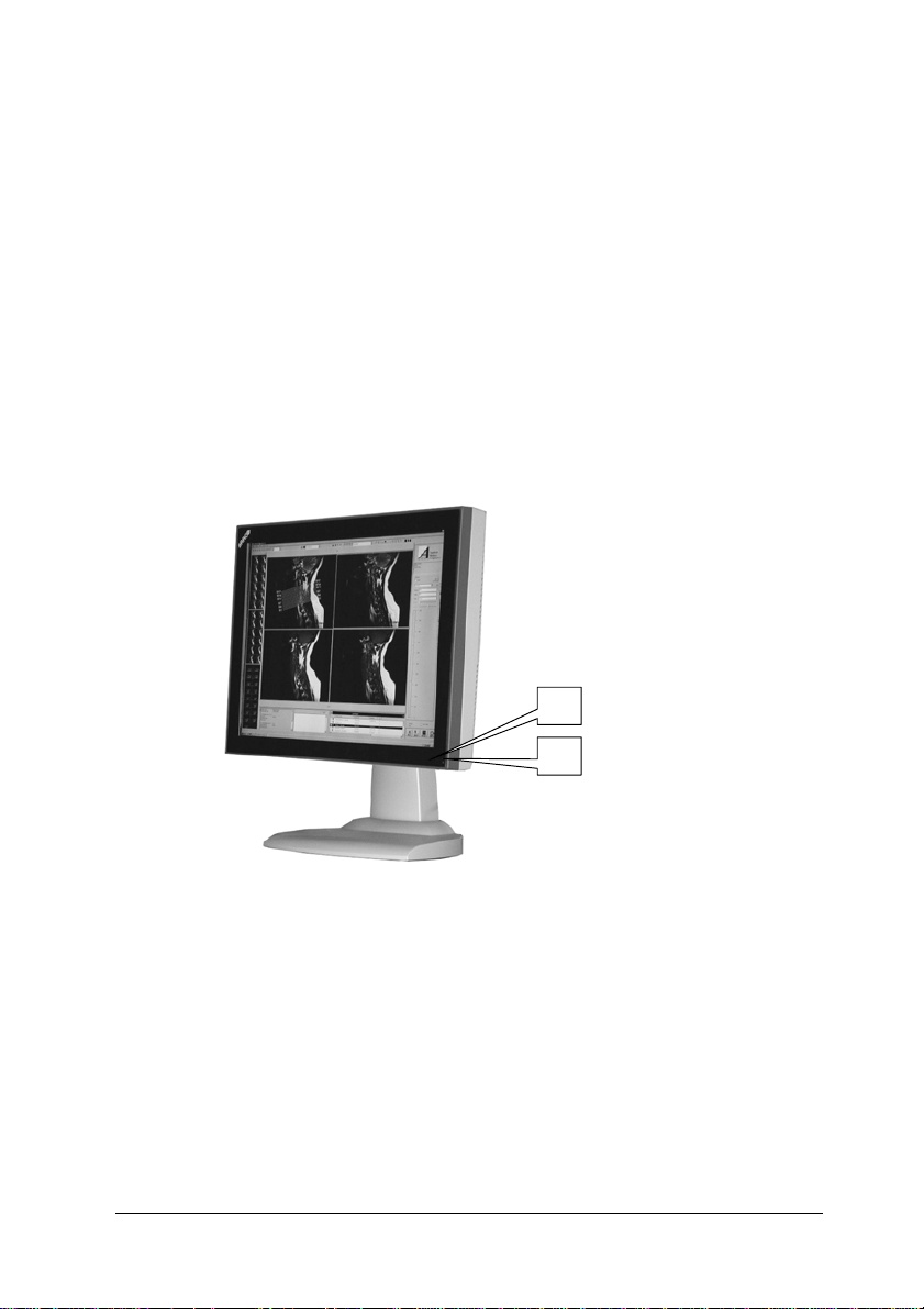
1.3. Controls and connectors
1
2
(1) Ambient Light Compensation (ALC) sensor
(2) Power LED
- The LED is off when the display is off or disabled in the on-screen
menus.
- The LED is green when the display is on (when enabled in the onscreen menus).
- The LED is orange when the display is in Stand-by power-saving
mode.
User manual MIVD 1218
7
Page 8
r
Connector not used
3
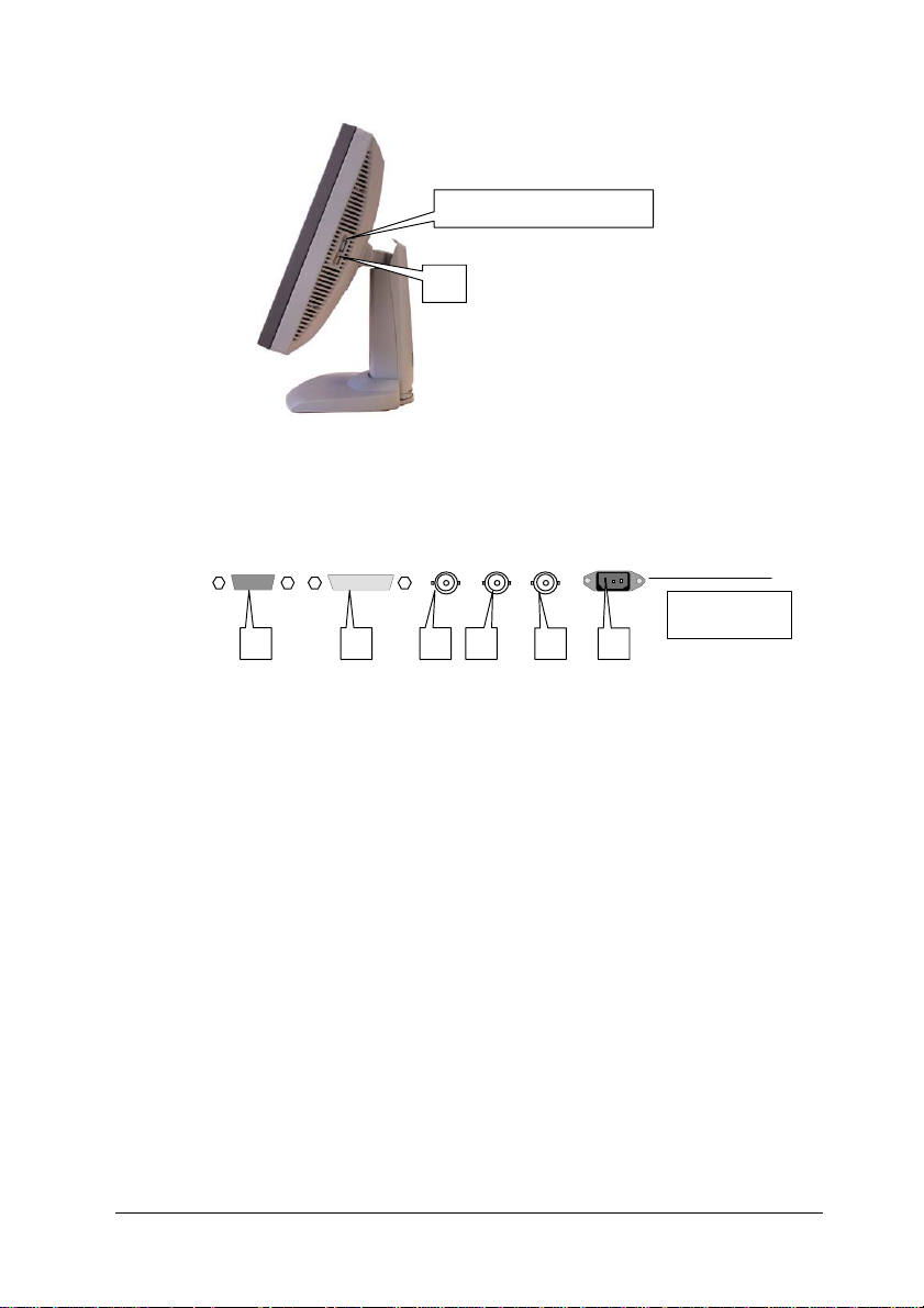
(3) Control wheel for navigating through the on-screen display (OSD)
menus and changing values in the menus
RS232 DVI VIDEO CS/HS VS
(SERVICE ONLY)
4 5 6 7
Power
8 9
Input panel
at the rea
(4) Control (rs-232) connector
Note: To comply to EMC regulations, the used RS-232 cable must
be provided with a ferrite core.
(5) DVI (video and data) input
(6) Composite video input
(7) Composite / Horizontal sync input
(8) Vertical sync input
(9) AC power input
User manual MIVD 1218
8
Page 9
2. Installation
2.1. Precautions
• Keep your original packaging. It is designed for this display and is
the ideal protection during transport.
• Avoid reflections in the flat panel to reduce eye strain.
• Place the display on a strong and stable table or desk.
• Keep the display away from heat sources and provide enough
ventilation in case it is built in a rack or console.
• Make sure all equipment is switched off before connecting the
signals.
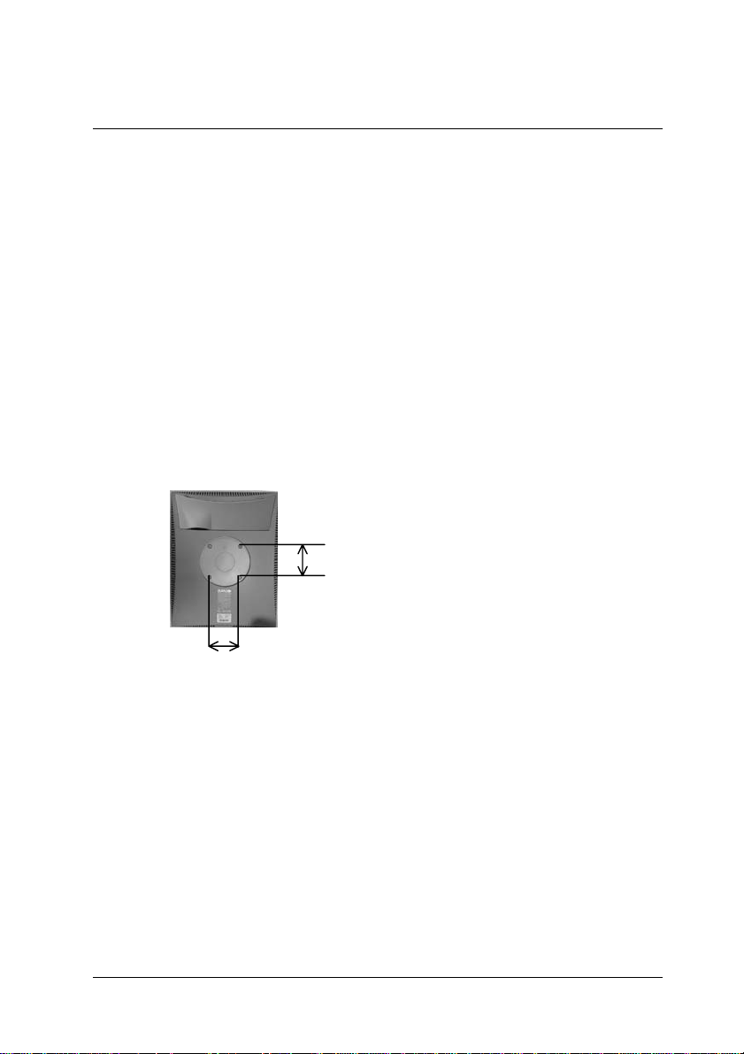
2.2. Mounting the display
(model without tilt & swivel foot option)
The standard display comes without tilt & swivel foot.
It is provided with 4 holes in the rear cover to mount the display to a
“Vesa 100 mm” standard mounting bracket.
100 mm
Screws: 4 screws M4 x 8 mm
100 mm
2.3. Portrait or landscape position
(model with tilt & swivel foot option)
You can change the orientation of the panel at any time, but it is
more convenient to select landscape or portrait orientation before
connecting the cables.
Important:
In the factory, the height-positioning system in the display foot is
blocked with a strap to prevent damage during transportation.
Before installing the display, you must remove this strap.
User manual MIVD 1218
9
Page 10
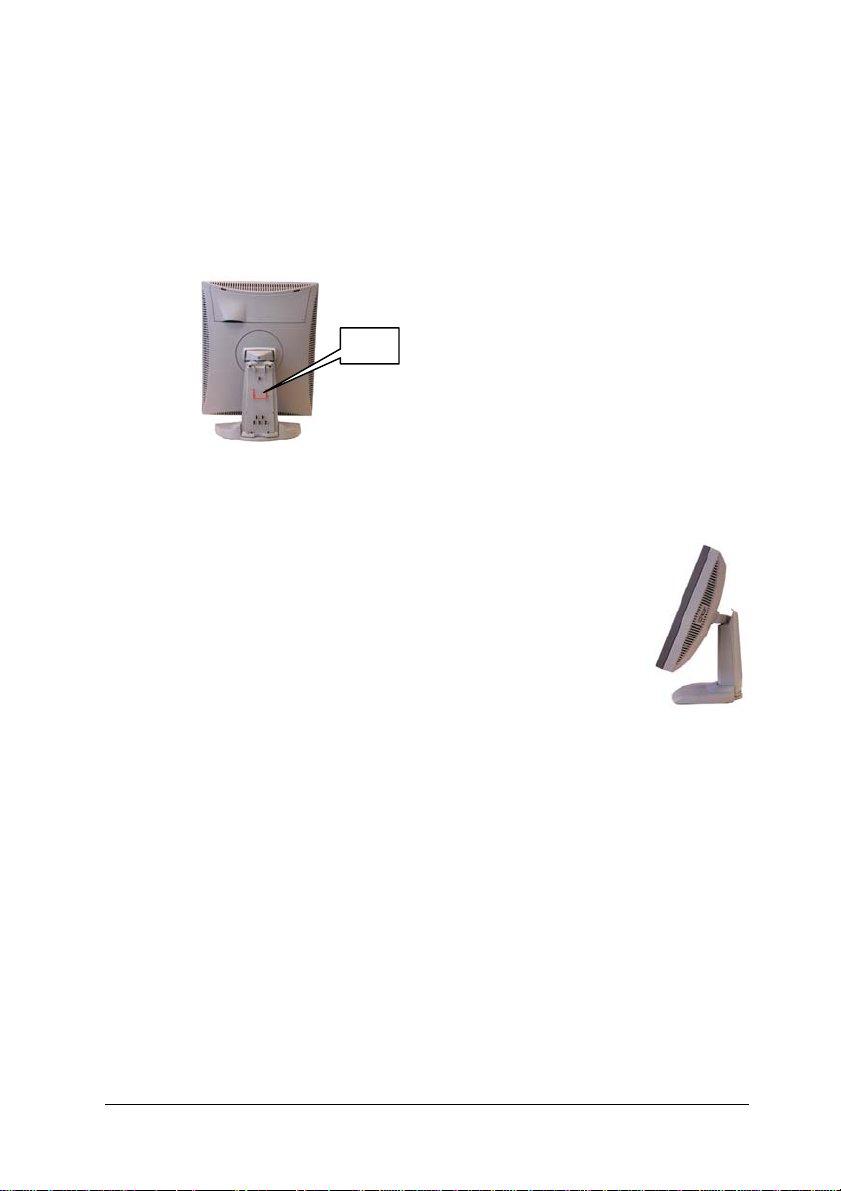
To remove the strap:
1 Position the display with its rear side facing you.
2 If the foot cover is mounted on the foot, lift up the 2 clips of the
foot cover to release the cover from the foot.
3 Pull the lower side of the cover towards you and simultaneously
slide the cover downward.
4 Pull the red strap out of the fixation holes in the foot.
Strap
To change the panel orientation:
1 Stand at the front side of the panel and take the panel at both
sides.
2 Very important: Tilt the panel before changing
the orientation.
Should you change the panel orientation without
tilting it first, you might irreversibly damage the
tilt & swivel mechanism.
3 To change from portrait to landscape, turn the
panel counterclockwise while tilting it slightly.
To change from landscape to portrait, turn clockwise.
2.4. Connecting the signals
To get access to the connectors, open the cover of the connector
compartment by pulling down the 2 clips of the cover.
To connect DVI signals:
1 Connect one end of the DVI cable to the DVI input (5) of the
display.
2 Connect the other end of the DVI cable to the video output of your
DVI signal source.
3 Rout the cable so that it enters the connector compartment at the
place where the cover is bulged.
User manual MIVD 1218
10
Page 11

To connect analog video & sync signals:
Connect the video & sync output of the signal source to the video
and sync inputs (6), (7) and (8) of the display.
The inputs accept the following signals:
• Video with separate horizontal and vertical sync.
- The connection consists of 3 cables.
- Connect the video signal to the connector Video (6).
- Connect the horizontal sync signal to connector HS/CS (7).
- Connect the vertical sync signal to the connector VS (8).
- Make sure the signal connected to the HS/CS connector does
not contain Composite sync.
• Video with external composite sync.
- The connection consists of 2 cables.
- Connect the video signal to the connector Video (6).
- Connect the composite sync signal to connector HS/CS (7).
- Make sure no signal is connected to the VS connector.
• Video with internal composite sync (sync on video).
- The connection consists of 1 cable.
- Connect the video (with sync) signal to connector Video (6).
Notes:
• The video inputs cannot be connected in loop-through (daisychain).
• The required video amplitude: 700 mV ± 3 dB.
• The required sync. amplitude: 500 mV.
To connect the power:
1 Plug one end of the power cord into the rear of the display
(connector (9)).
2 Plug the other end into a grounded AC power outlet.
3 The display automatically adapts to the voltage. The voltage
range is: 90-264 VAC.
After fixing the cables, put the connector compartment cover back in
place. Pay attention that the signal cables are positioned under the
bulge in the cover.
User manual MIVD 1218
11
Page 12

2.5. Routing the signal cables
(model with tilt & swivel foot option)
After connecting all cables, fix them in the cable tie at the rear of the
connector compartment. Bind the cables together above and under
the foot, by means of the 2 velcro strips included in the package.
After fixing the cables, put the connector compartment cover back in
place. Pay attention that the signal cables are positioned under the
bulge in the cover.
Next, fix the cables in the plastic clamps on the foot. At last, put the
foot cover back in place.
To put the foot cover in place:
1 Push the upper side of the cover onto the foot, so that the hooks
on the cover are positioned right under the holes in the foot.
2 Slide the cover upward while moving the lower side of the cover
towards the foot.
3 Press the cover to the foot so that both clips make a clicking
sound.
Push the upper
side of the
cover onto the
foot
Connector
compartment
Signal cables
routed under
foot cover
and bound by
velcro strips
User manual MIVD 1218
12
Page 13

2.6. Tilt and swivel positioning
(model with tilt & swivel foot option)
Adjust the position of the panel for best viewing conditions.
The display foot allows adjusting the horizontal viewing angle,
vertical viewing angle and panel height.
2.7. Starting up
Proceed as follows:
1 Switch on the signal source.
2 If necessary, select a suitable resolution or signal format for the
signal source.
3 Important: When using the display for the first time, perform the
Phase and Level calibrations on each mode you are using. This
takes only a few seconds and is necessary to guarantee a perfect
image quality.
For more details, see § 3.4 : Calibrating the display .
User manual MIVD 1218
13
Page 14

3. Operation
3.1. Introduction
The control wheel (3) at the bottom (landscape
orientation) or at the side (portrait orientation)
allows you to perform controls.
The control wheel is a rotation - click system. It
provides the following functions:
• Short click: Enter menus, confirm selections,
and toggle between different options
• Long click: Exit menus
• Rotate: Browse through menus, increase or decrease adjustment
values
Navigating through the menus
• The menu system has a hierarchical structure, with several levels.
To display the on-screen menus, click or turn the wheel (3). The
Main Menu appears. This is the top level of the menu system.
• To browse or scroll through the menus on the current level, turn
the wheel clockwise or counter-clockwise.
• To enter into a menu or move to a lower level of the menu
structure, click the wheel shortly.
• To exit from a menu or move to a higher level of the menu
structure, click and hold the wheel for a few seconds.
If you do this when you are in the Main Menu, you exit the menu
system.
• To execute one of the controls or change a value:
- Click the wheel shortly to select the control
- Turn the wheel to change the value
- Click the wheel shortly to confirm the change
3
Saving changes
Most of the settings and values you can change in the menu system,
are related to the memory scan modes. E.g., for each scan mode,
you can select a particular look-up table.
When you try to exit the menu system while you have changed any
of the scan mode related parameters, the menu system will ask if you
wish to save the changes:
Save Changes (3)
EXIT , Press long
User manual MIVD 1218
14
Page 15

a) To save the changes, click and hold the control wheel for a few
seconds.
b) To exit the menus without saving the changes:
1 Turn the control wheel. The check mark in the menu changes
into a cross (2).
2 Click and hold the control wheel for a few seconds.
When you make adjustments and save the changes, the current scan
mode is saved as programmable scan mode. If this happens while all
programmable scan modes are occupied, the oldest programmable
scan mode is overwritten automatically.
3.2. Controlling contrast and brightness*
* Not in DVI mode
To enter the menu:
1 Turn the control wheel to display the Contrast or Brightness
menu.
***MAIN MENU****
Contrast
***MAIN MENU****
Brightness
2 Click the control wheel to enter the Contrast or Brightness menu.
You can change the current setting manually or select the
calibrated position.
To change contrast or brightness manually:
1 Turn the control wheel to select the manual contrast (brightness)
control.
***Contrast****
Contrast 158
***Brightness***
Brightness 64
2 Click the control wheel to enter the control.
*IIIIIIIIIIIIIIIIIIII
Contrast 158
.......................
*IIIIII
Brightness 64
3 Turn the control wheel to change the contrast or brightness value.
4 Click the control wheel to confirm the change of the value.
User manual MIVD 1218
.........
*
*
15
Page 16

5 Click and hold the control wheel for a few seconds to exit the
menu.
To select the calibrated position:
1 Turn the control wheel to select the “Calibrated” selection menu.
***Contrast****
Calibrated (
***Brightness***
Calibrated (
2 A cross (2) in the menu means the contrast (brightness) is
actually not calibrated.
A check mark (3) means the contrast (brightness) is actually in
calibrated position.
3 If the current setting is not calibrated (2), click the control wheel to
switch to the calibrated position.
4 Click and hold the control wheel for a few seconds to exit the
menu.
2)
2)
Additional information
- If you change contrast or brightness manually, the changed value
is not saved in the memory. This means that after switching off
the display or after switching to a different memory scan mode,
the value for contrast and brightness is restored to the calibrated
position.
- The calibrated position for contrast and brightness is determined
by calibration of the video levels (see § 3.4 below).
In case you feel unsatisfied with the current calibrated position,
you need to repeat the calibration. The proper way to do this, is to
use the automatic calibration routine. However, you can also
manually change the calibrated positions: The Manual black
control changes the brightness calibrated position, Manual white
changes the contrast calibrated position.
3.3. Controlling the light output
The Light Output control adjusts the backlight of the flat panel.
To control the light output:
1 Turn the control wheel to display the Light Output menu.
***MAIN MENU****
Light Output 136
User manual MIVD 1218
16
Page 17

2 Click the control wheel to enter the menu.
3 Turn the control wheel to change the light output value.
4 Click the control wheel to confirm the change of the value.
..................
*IIIIIIIII
Light Output 136
5 Click and hold the control wheel for a few seconds to exit the
menu.
Note:
Unlike the contrast and brightness values, the changes to the light
output setting are saved immediately after changing the value.
When you switch on the display, it comes up with the same light
output value as before switching it off.
*
3.4. Calibrating the display*
* Not in DVI mode
When do you need to calibrate?
It is necessary to perform the Level and Phase calibrations in the
following cases:
• The first time you use the display
• After connecting or selecting another video source
We recommend you use the automatic calibration routines only. The
manual calibration controls are intended for advanced users who
wish to fine-tune the automatic calibration result.
Required test pattern
To obtain good results with the automatic calibration routines, it is
necessary to have a good image on which to perform the
calibrations.
For Phase calibration, the pattern should contain sharp black-white
transitions, like a line pattern or characters.
For Level calibration, the pattern should contain parts that are
completely black (0% video amplitude) and parts that are full white
(100% video amplitude).
For Total Autoset, the pattern should contain:
- sharp black-white transitions (see above)
- 0% and 100% video parts (see above)
- white or gray (min. 50%) pixels at the edges of the image (left,
right, top and bottom).
User manual MIVD 1218
17
Page 18

To perform the calibrations:
1 Turn the control wheel to display the Calibration menu.
***MAIN MENU****
Calibration
2 Click the control wheel to enter the Calibration menu.
3 Turn the control wheel to select the calibration you wish to
perform.
4 For the automatic calibrations: Click the control wheel to perform
the calibration. During the calibration, the progress bar in the onscreen display is filled out.
After successful calibration, the on-screen display shows the word
"Successfully".
After unsuccessful calibration, the on-screen display shows the
word “Failed”. Please refer to chapter 5 : Troubleshooting for
more information.
5 For manual calibrations:
a) Click the control wheel to enter the menu.
b) Turn the control wheel to change the contrast or brightness
c) Click the control wheel to confirm the change of the value.
6 After calibration, click and hold the control wheel for a few
seconds to exit the Calibration menu.
value.
The different calibration functions:
Total Autoset ............This function performs the automatic detection
of the number of pixels (horizontal and vertical)
and all other calibration functions (described
below) one after the other. This function takes a
few minutes.
Phase & level ...........Automatic calibration of the video sampling
phase and the video levels (black and white)
Auto level..................Automatic calibration of the video levels (black
and white)
Auto phase ...............Automatic calibration of the video sampling
phase
Manual phase...........Manual adjustment of the video sampling phase
Manual black ............Manual adjustment of the video black level
(brightness cal setting)
Manual white ............Manual adjustment of the video white level
(contrast cal setting)
User manual MIVD 1218
18
Page 19

Note:
The calibration of the video levels determines the calibrated position
or default setting of contrast and brightness. The black level
calibration determines the brightness, the white level calibration
determines the contrast.
3.5. Getting information
The Information menu allows you to get a lot of information about the
display and the connected signals.
To read the information:
1 Turn the control wheel to display the Information menu.
***MAIN MENU****
Information
2 Click the control wheel to enter the menu.
3 Turn the control wheel to select one of the categories: General or
Timing.
4 Click the control wheel to enter the selected information menu.
5 Turn the control wheel to scroll through the information.
General information
Input .........................Displays the currently selected input: analog
Current Mode ...........Displays the currently selected memory scan
ALC ..........................Displays if the Ambient Light Compensation
Power Led ................Displays if the power LED on the front is
Interlaced* ................Indicates if the display is processing the
Filter*........................Displays which internal low-pass filter is
Serial #. ....................Indicates the display serial number
SW ...........................Displays the current internal software version
composite video or DVI (digital)
mode
(ALC) is on or off. A check mark (3) means on,
a cross (2) means off
currently switched on or off. A check mark (3)
means on, a cross (2) means off
selected input signal in interlaced or noninterlaced mode. A check mark (3) means
Interlaced, a cross (2) means non-interlaced
currently selected
User manual MIVD 1218
19
Page 20

Lifetime.....................Indicates the total time the display has been
operating, including the time in power-saving
mode
* Not in DVI mode
Timing information
V.Freq.......................The currently measured vertical sync frequency
H.Freq ......................The currently measured horizontal sync
frequency
Interlaced* ................Indicates if the connected video signal is
interlaced or non-interlaced. A check mark (3)
means Interlaced, a cross (2) means noninterlaced
Inp.Clk*.....................The current dot clock frequency with which the
input signal is sampled
Lines/Frame .............The actually measured number of total lines per
frame. For interlaced signals, a frame consists
of 2 fields.
Sync*........................The kind of connected sync
* Not in DVI mode
3.6. Adjusting Geometry
The Geometry menu allows you to adjust the parameters with which
the input video signal is sampled. As a consequence, the image
geometry is influenced.
Required test pattern
To obtain good results with the Autocenter function, it is necessary to
have a good image on which to perform the adjustment.
For Autocenter, the pattern should contain:
- white or gray (min. 50%) pixels at the edges of the image (left,
right, top and bottom).
To perform the adjustments:
1 Turn the control wheel to display the Geometry menu.
***MAIN MENU****
Geometry
2 Click the control wheel to enter the menu.
User manual MIVD 1218
20
Page 21

3 Turn the control wheel to select one of the geometry adjustment
menus.
4 Click the control wheel to enter the selected menu.
5 Turn the control wheel to change the value.
6 Click the control wheel to confirm the change.
These are the geometry adjustments:
Auto Center*.............Automatically positions the image in the center
of the display panel.
Pix/line* ....................Adjusts the number of pixels per line with which
the video signal is sampled. To obtain an
unscaled and undistorted image reproduction,
you have to fill out the total number of pixels per
line, as defined in the timing parameters of the
input signal.
V-position .................Adjusts the image position vertically
H-position .................Adjusts the image position horizontally
V-Active ....................Allows you to change the vertical size of the
active video window around the image,
expressed in pixels. If you decrease this size,
you may blank a part of the image.
H-Active....................Allows you to change the horizontal size of the
active video window around the image,
expressed in pixels. If you decrease this size,
you may blank a part of the image.
Scaling On................When switched on, the image will be scaled
automatically when possible. E.g., if the image
is 640x480 pixels, the image will be scaled by a
factor 2. But an image of 800x600 pixels will not
be scaled because the native panel resolution
is 1280x1024 pixels.
* Not in DVI mode
3.7. Settings
To change the settings:
1 Turn the control wheel to display the Settings menu.
***MAIN MENU****
Settings
2 Click the control wheel to enter the menu.
User manual MIVD 1218
21
Page 22

Input Selection
3 Turn the control wheel to select one of the categories: Input
selection, Test Pattern, Synchr. Sampl, Lookup Tables, Filter,
Power Led, ALC active, or de-interlacing.
4 Click the control wheel to enter the selected settings menu.
5 Turn the control wheel to change the setting.
6 Click the control wheel to confirm the change.
This setting allows you to define how the display will determine which
input to select: Analog (composite video input) or DVI.
These are the possibilities:
Automatic .................If Automatic is selected, the selection of the
input is determined according to the following
priority: 1) DVI input, 2) BNC inputs
A check mark (3) means On, a cross (2)
means Off.
Analog ......................When on, the analog video input is selected.
Consequently, the Automatic setting will be
switched off.
A check mark (3) means On, a cross (2)
means Off.
DVI ...........................When on, the DVI input is selected.
Consequently, the Automatic setting will be
switched off.
A check mark (3) means On, a cross (2)
means Off.
Test Pattern
The display contains an internal grayscale test pattern. Switch it on in
case you want to do a quick visual check on the display quality.
A check mark (3) means it is switched on, a cross (2) means it is off.
Note: The test pattern runs independent from the signal input and the
actual scan mode.
Lookup Tables
This setting allows you to select a lookup table for the current scan
mode.
You can select the following lookup tables:
Panel ........................Select a panel lookup table in case the graphic
board that generates the video signal already
provides gamma correction, a display function
or a non-linear lookup table.
User manual MIVD 1218
22
Page 23

DICOM .....................Select a DICOM lookup table for most medical
viewing applications. The DICOM function
results in more visible grayscales in the images.
CRT..........................Select a CRT (gamma) lookup table in case the
display is used to replace a CRT display.
Apart from these factory lookup tables, there is a User
lookup table. It is default filled out with the DICOM lookup table
(dedicated software needed to re-program it).
programmable
Filter*
* Not in DVI mode
The display electronics provide 4 different low-pass filters to filter
possible high-frequent distortion from an analog video signal.
Select a different filter in case the image contains high-frequent noise
or distortion. Select the filter that gives the best result.
Re-calibration of the phase is necessary after selection of a different
filter.
Power Led
This setting allows you to switch off the power LED.
A check mark (3) means it is switched on, a cross (2) means it is off.
Note:
The LED’s orange DPMS state is not influenced by this setting. So,
when the display goes into power-saving mode, the LED will turn
orange, even if it was switched off by this setting.
ALC active
This setting allows you to switch ALC (Ambient Light Compensation)
off or on.
The ALC system automatically adapts the display light output,
depending on the ambient light in the room. The ambient light is
measured by the ALC optical sensor located at the front of the
display.
DPMS active
This setting allows you to switch DPMS (Display Power Management
System) off or on
Orientation**
** Only when Portrait Accelerator is installed
Select the desired option:
User manual MIVD 1218
23
Page 24

A
De-interlacing*
Auto..........................The display selects portrait or landscape
reproduction automatically, depending on the
orientation of the panel.
Portrait......................The image is reproduced in portrait orientation.
Landscape: The image is reproduced in
landscape orientation.
* Not in DVI mode – Visible only when the input signal is interlaced
This setting allows you to select the algorithm used to convert noninterlaced into interlaced signals.
These are the possibilities:
Line rep. ...................Use the line repetition algorithm for moving
images. As a drawback, this algorithm may
cause flicker.
Field insert................Use this algorithm for static images
Median......................Use this algorithm for images containing static
and moving parts
Fuzzy........................This motion-adaptive algorithm, using fuzzy
logic, analyses the image content and selects a
de-interlacing method automatically.
In nearly all circumstances, this method gives
the best result and is the preferred deinterlacing algorithm.
3.8. Advanced settings
To change the advanced settings:
1 Turn the control wheel to display the Advanced Settings menu.
***MAIN MENU****
dv. settings
2 Click the control wheel to enter the menu.
3 Turn the control wheel to select one of the categories: CAL
options, Meas. window, OSD, ALC, Scan mode, or Factory Reset.
4 Click the control wheel to enter the selected settings menu.
5 Turn the control wheel to change the setting.
6 Click the control wheel to confirm the change.
CAL options
Here you can change parameters for phase and level calibration
User manual MIVD 1218
24
Page 25

Equal pix...................Selects the number of successive pixels with
the same digital value used in amplitude and
black level calibration.
Decrease this number for video signals with a
lot of noise.
Phase offset .............Adds a phase difference to the value derived
after phase calibration.
This can be used to compensate for distortions
on the video signal.
Apix Range...............Contains the functions Clk Start and Clk Stop.
These are the numbers of pixels for the Autocal
routine to start and stop with.
By default, the number of lines in the image is
taken as the number of pixels for Autocal to
start its calculations. The double of this start
number is taken as the number of pixels for
Autocal to stop. By increasing the start number
and decreasing the stop number, you narrow
the range for the Autocal routine. As a result,
Autocal goes faster.
OSD
Here you can change some of the on-screen display’s (OSD)
parameters.
These are the OSD settings:
Hor. Pos ...................The horizontal position
Vert. Pos...................The vertical position
Timeout On...............To switch the OSD timeout on or off. A check
mark (3) means it is switched on, a cross (2)
means it is off.
When switched on, the OSD disappears
automatically after 300 seconds of inactivity.
ALC
ALC (ambient light compensation) is a system that adapts the panel
light output automatically, based on the ambient light measured by
the ALC sensor at the front of the display.
Here you can adjust the ALC parameters.
These are the ALC settings:
min Light...................This is the panel light output that corresponds
to the minimum ambient light, measured by the
ALC sensor.
User manual MIVD 1218
25
Page 26

max Light..................This is the panel light output that corresponds
to the maximum ambient light, measured by the
ALC sensor.
min Thresh ...............This is the minimum value of ambient light.
Below this value, ALC will remain inactive.
When the measured ambient light reaches this
value, the panel light output will be set to the
min Light value.
max Thresh ..............This is the maximum value of ambient light.
Above this value, ALC will stop controlling the
light output. When the measured ambient light
reaches this value, the panel light output will be
set to the max Light value.
Scan mode
The memory of the display contains maximum 200 fixed and 28
programmable scan modes.
When you connect a video signal, the display checks in the memory
for a matching scan mode.
If it finds one, it selects the corresponding settings and parameters
from the memory. If it does not find a matching scan mode, the
display uses default settings to display the image.
When you make adjustments and save the changes, the current scan
mode is saved as programmable scan mode. If this happens while all
programmable scan modes are occupied, the oldest programmable
scan mode is overwritten automatically.
The Scan Mode menu contains the following function:
Find next mode.........Select if you wish to select another scan mode
from memory that matches the incoming video
and sync signals. The number displayed in the
OSD is the number of the actual scan mode’s
memory location.
Factory reset
Can be used to re-initialize the display.
Actual mode .............Restores all factory parameters for the current
programmable mode.
All modes..................Restores all factory parameters for all
programmable modes.
Control wheel
This function allows you to disable the control wheel function so that
the on-screen display cannot be used.
User manual MIVD 1218
26
Page 27

To disable the control wheel function, set the Control wheel function
to Off and exit the on-screen menus.
To enable the control wheel function again:
1 Unplug the power supply from the display
2 Click and hold the control wheel while plugging in the power
supply again
3.9. Service
This menu is for service purposes only.
User manual MIVD 1218
27
Page 28

4. Maintenance
Panel
Take care not to damage or scratch the panel. Clean with a soft
woolen or cotton towel. Use a watery solution or a mild commercial
glass-cleaning product.
Cabinet
Do not use chemical cleaning products, benzene, toluene, xylene or
other solvents. Clean with a soft cloth dampened with mild detergent
and water. Repeat with water only and wipe dry with a dry cloth.
Removing dust from the rear of the glass panel
It may be possible that dust particles have entered the display and
are stuck to the rear of the glass.
We recommend to let this cleaning procedure be done in a BARCO
service center.
However, when really necessary, you can perform the cleaning on
site if you can work in conditions that are as clean and dust-free as
possible. This is to avoid more dust entering the display when
opening it.
To remove the glass panel:
1 Switch off the display.
2 Tilt the panel.
3 Unscrew the 4 sunken screws at the rear, fixing the glass panel
and bezel.
4 Remove the bezel with glass panel.
Cleaning instructions:
- Dust, fingerprints, grease etc. can be removed by using a soft
damp cloth (a small amount of mild detergent can be used on the
cloth, NOT solvent).
- Do not apply liquid directly to the LCD surface as excess liquid
may cause damage to internal electronics.
- Take care not to touch the I-guard light sensor on the LCD panel.
User manual MIVD 1218
28
Page 29

5. Troubleshooting
Calibration not successful
After an unsuccessful calibration, the message “Failed” appears on
the screen.
Possible solutions:
- Use another test pattern for performing the calibration. The text in
§ 3.4, Calibrating the display , explains what test patterns to use.
- Check the quality of the signal source and signal cables. Poor
video signals or cables can result in unsuccessful calibration.
Pixel Faults
Permanently dark or bright pixels can happen to TFT displays. 20 or
less permanently dead pixels do not make out a good case for
exchanging the unit.
Please contact our Customer Service Department if the number of
pixel faults exceeds the above-mentioned figure.
User manual MIVD 1218
29
Page 30

6. Technical specifications
GEOMETRY
• Screen size: 46 cm
(18.1")
• Display area: 359 mm x
287 mm (14.1" x 11.3")
• Aspect ratio: 5:4
VISUAL PERFORMANCE
General
• Pixel arrangement: subpixel vertical stripes
• Pixel pitch: 0.2805 mm x
0.2805 mm (0.011" x
0.011")
• Panel contrast ratio:
550:1 (typical)
• Panel viewing angle: +/85° (at CR = 10:1)
Panel
• Thin film transistor active
matrix grayscale LCD
• PVA technology
• Amorphous silicon TFT
• Backlight: 6 cold
cathode fluorescent
lamps
Luminance
• Calibrated: 500 cd/m2
(145.9 fL)
Resolution
• Up to 1280 x 1024 (1.3
MegaPixel)
INPUTS
DVI
• Complies to DVI Rev.
1.0 spec
Video
• Connector type: BNC
• Inputs provided:
composite video
• Video input voltage:
nominal 0.7Vpp
• Termination: 75 Ohm
Sync
• Connector type: BNC
• Inputs provided: HS/CS
and VS
• Sync input voltage:
nominal 2Vpp
• Termination: 75 Ohm
SCANNING SYSTEM
• Horizontal Frequency:
15 - 95 kHz
• Vertical Frequency: 50 140 Hz
• Interlaced / noninterlaced signals
• Interlaced: Fuzzy-logicbased de-interlacing
• Multi-sync
• 14 programmable scan
modes
User manual MIVD 1218
30
Page 31

CONTROLS
• On-Screen Display
(OSD)
• Rotary / push control
APPROVALS
CE, IEC601-1, UL 2601-1,
CUL 2601-1
DIMENSIONS
wheel to navigate
through the OSD
• RS232
POWER SUPPLY
H x W x D:
371 x 444 x 90 mm
(14.6 x 17.5 x 3.5 inch)
• Mains input voltage:
automatic 90 - 264 Vac
Freq. 50/60 Hz
Due to our policy of continuous product improvement, the above specifications are
subjected to change without notice. Barco shall not be liable for technical or editorial
errors or omissions contained herein; nor for incidental or consequential damages
whatsoever resulting from furnishing, performance or use of this material.
© 2002 BARCO N.V. All rights reserved
User manual MIVD 1218
31
 Loading...