

Page 1

B4100528 / 03
November2005
MFCD 1219 - MFCD 1219 TS
Installation & User Manual
Page 2
SAFETY INSTRUCTIONS
• Read the safety and
operating instructions before
operating the apparatus.
• Retain safety and operating
instructions for future
reference.
• Adhere to all warnings on
the apparatus and in the
operating instructions
manual.
• Follow all instructions for
operation and use.
•This apparatus conforms to:
UL60950, cUL60950,
IEC60950, CE
• FCC notice
This equipment has been
tested and found to comply
with the limits of a class B
digital device, pursuant to
Part 15 of the FCC rules.
These limits are designed to
provide reasonable
protection against harmful
interference when the
equipment is operated in a
commercial environment.
This equipment generates,
uses and can radiate radio
frequency energy and, if not
installed and used in
accordance with the
instruction manual, may
cause harmful interference
to radio communications.
Operation of this equipment
in a residential area is likely
to cause harmful
interference in which case
the user will be required to
correct the interference at
his own expense.
• This Class B digital
apparatus complies with
Canadian ICES-003.
Cet appareil numérique de
la classe B est conforme à la
norme NMB-003 du Canada.
Power connection
• Warning: This apparatus
must be earthed!
• Power requirements:
connect the apparatus to an
AC voltage as indicated at
its back. Using a lower
voltage, the apparatus will
not be able to operate. Using
a higher voltage may
damage the apparatus.
If you are not sure of the type
of power supplied, consult
the power company.
• Do not overload wall outlets
and extension cords as this
may result in fire or electric
shock.
• Mains lead protection (U.S.:
Power cord): Supply cords
should be routed so that they
are not likely to be walked
upon or pinched by items
placed upon or against them,
paying particular attention to
cords at plugs and
receptacles.
• Adapter manufacturer:
Linearity Electronics Co.
Ltd., Model: LAD6019AB5,
complies with UL Certified
Class 2 Power adapter or
UL Certified ITE Power
adapter with LPS, and
Suitable ratings.
• Power Supply Cord - Listed,
Detachable, maximum 4.5m
(14.76 ft.) long; rated
minimum 125 V, 2.5 A, Type
SPT-1 flexible cord; one end
terminates in parallel blade
(NEMA 5-20P) groundingtype attachment plug, other
end in appliance coupler.
Water and moisture
• Never expose the
apparatus to rain or moisture.
• Never use the apparatus
near water - e.g. near a
bathtub, washbasin,
swimming pool, kitchen sink,
laundry tub or in a wet
basement.
Ventilation
• Do not cover or block the
ventilation openings in the
cover of the set. When
installing the apparatus in a
cupboard or another closed
location, heed the necessary
space between the set and
the sides of the cupboard.
Installation
• Place the apparatus on a
flat, solid and stable surface
that can bear the weight of at
least 3 monitors. If you use
an unstable cart or stand,
the set may fall, causing
serious injury to a child or
adult, and serious damage
to the equipment.
© 2005 BARCO nv. Allrights reserved.
Page 3

CONTENTS
1. Overview ....................................................................................................... 5
1.1 Introduction ............................................................................................. 5
Multi-scan capabilities ............................................................................... 5
Touch panel ............................................................................................... 6
1.2 Package contents ................................................................................... 6
Power Saving............................................................................................. 6
1.3 Controls and connectors ............................................................................ 7
2. Installation .................................................................................................... 8
2.1 Precautions ............................................................................................. 8
2.2 Wall mounting ......................................................................................... 8
Step 1: Remove the panel from the foot .................................................... 8
Step 2: Fix the mounting plate to the wall.................................................. 8
Step 3: Place the panel on the mounting plate ......................................... 9
2.3 Connecting the signals......................................................................... 10
To connect the video & sync signals: ...................................................... 1 0
To connect the power: .............................................................................. 1 0
2.5 Install the software................................................................................. 11
2.4 Starting up .............................................................................................. 11
3. On-screen display (OSD) menus............................................................... 12
3.1 How to use the OSD ............................................................................. 1 2
3.2 Description of the menu items ............................................................. 13
Main menu ............................................................................................... 1 3
Color Menu .............................................................................................. 1 4
Clock Menu .............................................................................................. 15
4. Maintenance ............................................................................................... 16
Panel........................................................................................................ 16
Cabinet .................................................................................................... 16
Touch panel ............................................................................................. 16
Appendix A: Possible resolutions .................................................................. 17
Appendix B: Technical specifications ............................................................. 1 8
MFCD 1219 (TS) User's Guide 4
Page 4

1. OVERVIEW
1.1 Introduction
The MFCD 1219 (TS), BARCO’s full color 19”
LCD display, guarantees perfect image quality in
medical imaging applications.
The display combines a TFT (thin film transistor)
liquid crystal display panel structure and a built-in
backlight with inverter for a better picture quality.
It is designed to meet users' needs for
performance, consistency, and outstanding image
quality through a streamlined development
process in which wall-mount functionality
provides a variety of capability.
The image on the display can be adjusted by
means of the extended on-screen menu system
(OSD).
The internal memory can contain settings for 24
different types of video signals (with different
timings). 22 are factory-preset, 2 are userdefinable.
Multi-scan capabilities
The display accepts the most common display
standards. However, it is limited to the following
specifications:
Analog video:
The horizontal frequency must be between 31
and 91 kHz, the vertical frequency between 56
and 85 Hz.
Digital video:
The horizontal frequency must be between 31.47
and 64 kHz, the vertical frequency between 60
and 70 Hz.
The optimum and recommended resolution is
1280 x 1024 / 60 Hz.
MFCD 1219 (TS) User's Guide 5
Page 5

Power Saving
The monitor comes with a power saving feature;
therefore, you may put the monitor into a power
saving state when it is not in use. This feature
complies with both EPA‘s Energy Star
requirements and European NUTEK/TCO’s
power management guidelines. It conforms to
Video Electronics Standard Association (VESA)
approved DPMS power-down signaling method.
This monitor automatically cuts down power
consumption of monitor set when not detecting
Hsync or Vsync signals. This feature is compliant
with VESA DPMS.
Touch panel
The MFCD 1219 TS is equipped with a touch
panel. Instructions on how to install and use the
touch panel driver and controls can be found in
the "TouchKit, Barco TouchScreen controller
installation and user manual" on the supplied
CD-ROM.
1.2 Package contents
The package should include the following items,
please check. If some of the items are missing,
please contact the reseller you have purchased
the unit from.
- The display with foot
- 12V DC adapter
- European power cord
- American power cord
- UK power cord
- Video cables: VGA cable and DVI-D cable
- Mounting plate with 4 screws
- This user manual
- Calibration software CD-ROM
- USB cable for touch panel
MFCD 1219 (TS) User's Guide 6
Page 6
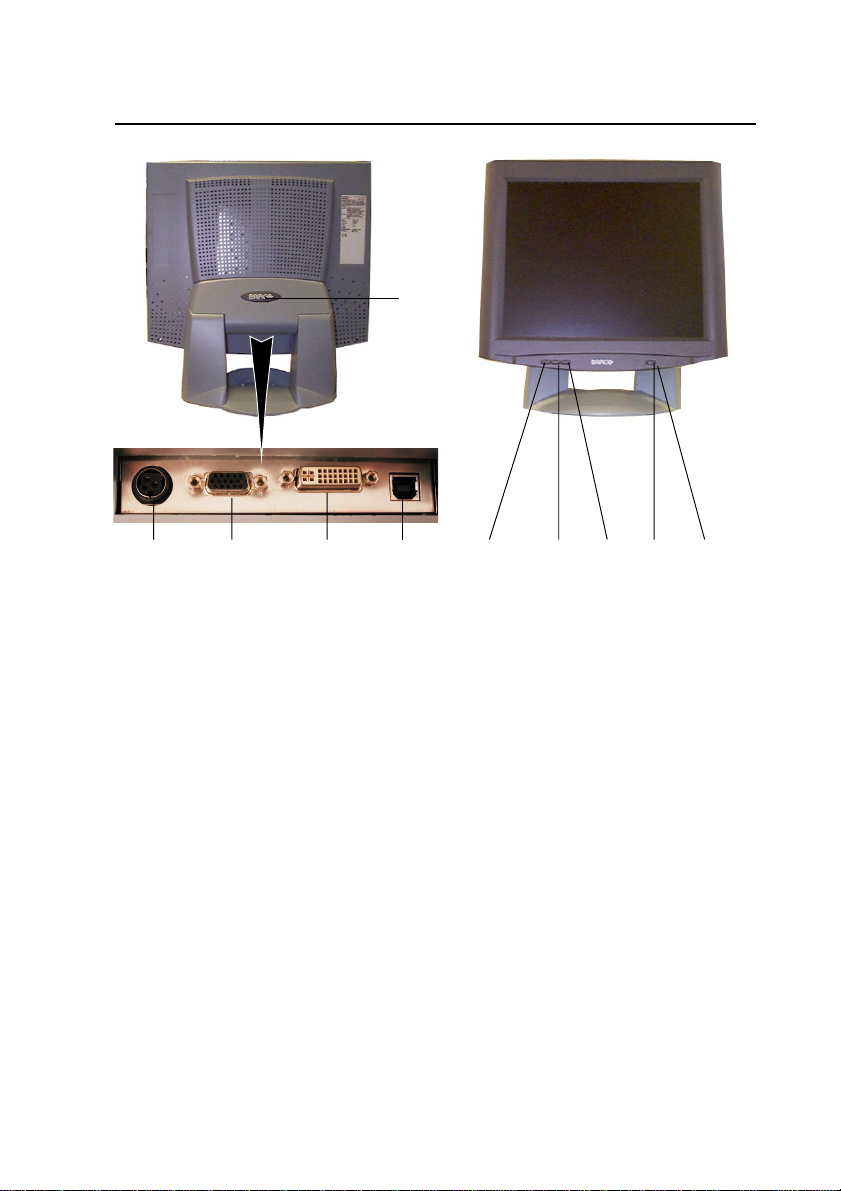
1.3 Controls and connectors
(10)
(1) (2) (3) (5) (6) (7) (8) (9)
(4)
(1) 12V DC power input
(2) Analog video input
(3) DVI input (DVI-D supported only)
(4) USB port for touch panel connection to PC
(MFCD 1219 TS only)
(5) Menu key
(6) <-> Key
(7) <+> Key
(8) Power LED
The LED is off when the display is off.
The LED is green when the display is on.
The LED is orange when the display is in
power-saving mode (stand-by)
(9) Power key
(10) Push-button to release the panel from the
foot
MFCD 1219 (TS) User's Guide 7
Page 7

2. INSTALLATION
2.1 Precautions
• Keep your original packaging. It is designed for this
display and is the ideal protection during transport.
• Avoid reflections in the flat panel to reduce eye
strain.
• Place the display on a strong and stable table or
desk.
• Keep the display away from heat sources and
provide enough ventilation in case it is built in a rack
or console. Do not put in direct sunlight.
• Make sure computer and display are switched off
before connecting the signals.
• Touch panel precautions: Operate with a stylus (tip
R0.8 or over, maximum hardness 3H), or with a
finger without applying excessive load. Sharp
edged or hard articles are prohibited. The gathering
of dew in the panel may occur with abrupt
temperature or humidity changes. A stable
environment condition is recommended. Keep the
surface clean. No adhesives should be applied.
Avoid high voltage and static charge.
2.2 Wall mounting
You can mount the panel to the wall instead of to
the foot, by means of the supplied mounting
plate. If you do not need to mount the panel to
the wall, please skip this item.
Step 1: Remove the panel from the foot
1 Position one hand under the panel at the
front side. Position the other hand at the
rear, under the push-button with BARCO
logo (9).
2 Firmly press down the push-button (9) with
one hand while carefully lifting the panel up
with the other hand.
3 Remove the panel from the foot.
Step 2: Fix the mounting plate to the wall
1 Screw the mounting plate to the wall with
the 4 supplied screws (A).
MFCD 1219 (TS) User's Guide 8
Page 8

A
2 Slide back the locks at both sides of the
mounting plate (B). In that way, you can
secure the panel to the mounting plate after
placing the panel.
B
Step 3: Place the panel on the mounting
plate
1 Place the panel on the mounting plate (C). If
you want to secure the panel to the
mounting plate, place the
panel in the frontmost
notches.
Please make sure that the
four shafts are securely
placed in the notches of the
mounting plate.
C
MFCD 1219 (TS) User's Guide 9
Page 9

2 To secure the panel, slide forward the
locks on both sides of the mounting plate.
Lock the panel with one screw at both
sides (D).
2.3 Connecting the signals
To connect the video & sync signals:
1 Connect one end of the appropriate video
cable to the corresponding video input of
the monitor.
Analog video: Connect to input (2)
DVI: Connect to input (3)
2 Connect the other end of the video cable to
the video output of your video source.
Analog video: Computer graphics board
with analog video output
DVI: Computer graphics board with digital
video output
D
(1) (2) (3)
To connect the power:
1 Connect one end of the proper power cable
to the AC input of the 12V DC adapter.
2 Connect the 12V supply of the 12V DC
adapter to the DC input (1) of the monitor.
3 Connect the other end of the power cord to
a grounded power outlet.
MFCD 1219 (TS) User's Guide 10
Page 10

2.4 Starting up
(8)
Proceed as follows:
1 Switch on the computer.
2 Switch on the display by pushing the Power
key (8).
3 If necessary, select a suitable resolution in
the computer operating system. Please
refer to Appendix A, "Possible resolutions"
in the back of this manual.
Note: The recommended resolution for best
image quality is 1280x1024 at 60 Hz.
The microcontroller in the display checks if the
connected video signal has been adjusted before,
and if these adjustments have been stored in the
memory. There are 2 possibilities:
a) The video signal has been adjusted and
stored in the memory.
In this case, the display switches to this memory
location (the so-called mode) and the image will
need no further adjustments.
b) The video signal has not been adjusted and
stored yet.
In this case, the display will auto-size the picture
and store the settings in one of the user modes.
2.5 Install the software
NioWatch software:
Insert the CD-ROM in the CD-ROM drive. The
CD-ROM starts automatically. Please follow the
instructions on the screen.
The CD-ROM contains user instructions about the
usage of the NioWatch.
Touch p anel software:
Please refer to the TouchKit installation & user
manual on CD-ROM.
MFCD 1219 (TS) User's Guide 11
Page 11

3. ON-SCREEN DISPLA Y (OSD)
H
MENUS
3.1 How to use the OSD
Proceed as follows:
1 Press the Menu key (4) on the front to display
the OSD main menu.
Note:
It may be possible that the OSD menu does
not appear. If this is the case, the front
Controls are locked. To unlock them, please
follow the procedure described in § 3.2 below.
2 Press the <+> key (6) or <-> key (5) to scroll to
the desired menu item.
3 Press the Menu key (4) to activate the
(4)
(5)
(6)
selected function or to enter the selected
secondary menu.
4 If you have activated a function:
a)Press the <+> key (6) or <-> key (5) to
change the value.
b)Press the Menu key (4) to enter the new
value and return to the menu.
5 To exit the OSD while saving the changes,
select Save & Exit.
To exit the OSD without saving the changes,
select Cancel.
Main Menu
ighlighted bar
- (Down) + (Up)
Brightness 35
Contrast 50
Auto Adjust
H Position 75
V Position 29
Color >
Clock >
Languages >
Input Type >
Lock Controls
Cancel
Save & Exit
automatically after an
inactivity period of 30
seconds.
The color of the highlight bar
indicates the status of the mode.
RED indicates the function is
selected and ready to be
adjusted.
Blinking RED indicates OSD is in
parameter adjusting mode.
MFCD 1219 (TS) User's Guide 12
Note: The OSD disappears
Page 12

3.2 Description of the menu items
Main menu
Function Description
Brightness To adjust the overall image and
background brightness level.
Contrast To adjust the image brightness in
relation to the background
(the background is unchanged).
Auto Adjust * To automatically set the H Position,
V Position and Clock.
Horizontal Position To move the screen horizontally
left or right.
Vertical Position To move the screen vertically
upward or downward.
Color To adjust parameters for the screen
colors of Red, Green and Blue.
Clock To adjust the function only when
characteristics are blurred.
Languages To select English, French, Italian,
German or Spanish for OSD
language.
Input Type To select Analog (A1) or
DVI-Digital (D) input source.
Lock Controls ** When locked, the OSD menu will not
appear when pressing the Menu key.
Cancel To restore the previous setting.
Save & Exit To save the adjustments and quit the
OSD menu.
*Auto Adjust function will be automatically
executed whenever the system is switched to a
new mode. When the system is changed to this
mode again later on, the system will not repeat the
Auto Adjust function. This function is only valid
when the mode concerned is selected for the first
time.
MFCD 1219 (TS) User's Guide 13
Page 13

Color Menu
**To unlock the Controls, proceed as follows:
1 Press the Power key to switch off the display
2 With one hand, press and hold the <+> and
the <-> key at the same time.
With the other hand, press the Power key
shortly to switch the display on again.
3 Keep holding the <+> and the <-> key for
about 3 seconds.
4 At last, release the <+> and the <-> key.
Now, by pressing the Menu key, the OSD
menu will appear.
Note:
The bottom line of the OSD shows the input type,
current resolution of the monitor and status of
vertical sync. If it shows user mode, one of the
user modes is selected.
Color Menu
- (Down) + (Up)
Auto Balance
Red
Green
Blue
Main Menu >
A1 1024 x 768 - 60.1 48.4k
68
65
70
Function Description
Auto Balance To automatically adjust the contrast
level of RGB. This does not support
resolution of Mac 832 x 624 at 75Hz.
R To adjust the level of color Red.
G To adjust the level of color Green.
B To adjust the level of color Blue.
Main Menu To return to Main Menu.
MFCD 1219 (TS) User's Guide 14
Page 14

Clock Menu
T o perform the Autobalance function, you need
to select a proper test pattern before performing
the function.
Proceed as follows:
1 You must have installed the Barco
NioWatch software.
2 Right-click on the NioWatch systray icon.
3 Select Test Patterns from the pop-up
menu.
4 Select the SMPTE test pattern.
5 Now perform the function Autobalance
from the MFCD 1219 (TS) control panel.
6 When finished, click on the test pattern to
close it.
Clock Menu
- (Down) + (Up)
OSD Position
Clock 1344
Clock Phase
Main Menu >
A1 1024 x 768 - 60.1 48.4k
Function Description
OSD Position To display the OSD to your preferred
4
Clock To adjust the function only when
Clock Phase To adjust ADC sampling clock phase.
Main Menu To return to Main Menu.
MFCD 1219 (TS) User's Guide 15
position.
characteristics are blurred.
Page 15

4. MAINTENANCE
Panel
Take care not to damage or scratch the panel.
Clean with a soft woolen or cotton towel. Use a
watery solution or a mild commercial glass
cleaning solution.
Cabinet
Do not use chemical cleaning products,
benzene, toluene, xylene or other solvents.
Clean with a soft cloth dampened with mild
detergent and water. Repeat this with water only
and wipe dry with a dry cloth.
Touch panel
(Only for MFCD 1219 TS)
Use a clean and soft clothe with neutral
detergent or with ethanol for cleaning.
Do not use any chemical solvent, acidic or alkali
solution.
Avoid spilling liquid inside the display. Apply the
liquid to the cloth, not to the panel.
MFCD 1219 (TS) User's Guide 16
Page 16

APPENDIX A: POSSIBLE
RESOLUTIONS
There are 22 preset modes and 2 user modes.
The following modes are preset as factory
defaults.
Resolution Pixel Horizontal Vertical Standard Analog Digital
640 x 350 25.175 31.47 70 VGA V V
640 x 480 25.175 31.47 60 VGA/VESA V V
720 x 400 28.321 31.47 70 VGA V V
800 x 600 36.00 35.10 56 VESA V
832 x 624 57.29 49.80 74.6 Mac V
1024 x 768 65.00 48.36 6 0 VESA V V
1152 x 864 108 67.50 7 5 VESA V
1280 x 1024 108 63.98 60 VESA V V
Freq. (MHz) Freq. (kHz) Freq. (Hz)
30.24 35.00 67 Mac V
31.50 37.90 72 VESA V
31.50 37.50 75 VESA V
36.00 43.30 83 VESA V
40.00 37.88 60 VESA V V
50.00 48.10 72 VESA V
49.50 46.88 75 VESA V
56.25 53.70 85 VESA V
75.00 56.50 70 VESA V
78.80 60.02 75 VESA/CRUS V
80 60.24 75 Mac V
94.50 68.70 85 VESA V
135 80 7 5 VESA V
157.5 91.146 85 VESA V
MFCD 1219 (TS) User's Guide 17
Page 17

APPENDIX B: TECHNICAL
SPECIFICATIONS
Picture panel
19-inch diagonal viewable screen
TFT (thin film transistor) active matrix,
color liquid crystal display, RGB
interface
Touch p anel (MFCD 1219 TS only)
Resistive technology
Interface: USB 1.1
Input mode: stylus or finger
Touch active force (stylus ∅ 0.8 mm):
<=50g
Input signals
Analog: Hor. 31.47 to 91.2 kHz
Vert. 56 to 85 Hz
Sync types: Separate sync,
composite sync, sync on
Green
Digital: Hor. 31.47 to 64 kHz
Vert. 60 to 70 Hz
Max. video input bandwidth
157.5 MHz
Resolution
1280 x 1024 (native)
Display area (H x V)
376 x 301 (mm)
Pixel Pitch
0.294 mm (H) x 0.294 mm (V)
Display color
16M
Luminance
280 cd/m2 (typ.)
MFCD 1219 TS: 230 cd/m² (typ.)
Contrast ratio
700:1 (typ.)
Response time
9 ms (typ. avg.)
Viewing angle
Vertical: 176º (typ.)
Horizontal: 176º (typ.)
Signal system
Analog RGB signals, DVI digital
Front panel controls
Menu, - (down / decrease), + (up /
increase), Power
Input connectors
15-pin D-sub
(for PC graphic signal input)
3P - Mini – DIN – Power –Connector
(for DC 12V, 6.5A input)
DVI connector (supporting DVI-D only)
Power source
100 ~ 240 VAC
Power consumption
50 W (max.)
Less than 5 W in power-off mode
Power saving
VESA DPMS standard
EPA/Energy Star compliant
MFCD 1219 (TS) User's Guide 18
Page 18

PnP compatibility
VESA DDC 2B standards compliant
Safety standards
UL60950, cUL60950, IEC60950, CE,
CCC
Dimensions (W x H x D)
450 mm x 461.8 mm x 213.9 mm
Net weight
7.7 kg
MFCD 1219 TS: 8.3 kg
Operating Temperature
0°C to 40°C
Storage Temperature
-20°C to 60°C
NOTICE:
DUE TO OUR POLICY OF
CONTINUOUS PRODUCT
IMPROVEMENT , THE ABOVE
SPECIFICATIONS ARE SUBJECTED
TO CHANGE WITHOUT NOTICE.
BARCO SHALL NOT BE LIABLE
FOR TECHNICAL OR EDITORIAL
ERRORS OR OMISSIONS
CONTAINED HEREIN; NOR FOR
INCIDENTAL OR CONSEQUENTIAL
DAMAGES WHA TSOEVER
RESULTING FROM FURNISHING,
PERFORMANCE OR USE OF THIS
MATERIAL.
MFCD 1219 (TS) User's Guide 19
Page 19

 Loading...