

Page 1
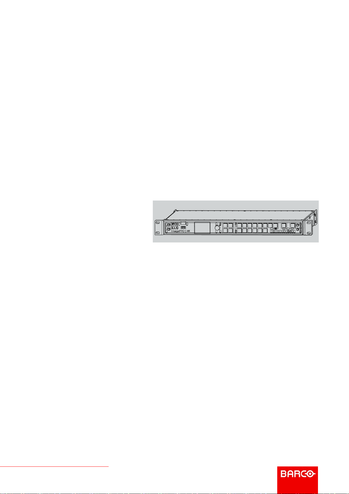
ImagePRO–4K Video Processor
ENABLING BRIGHT OUTCOMES
User’s Guide
Page 2

Barco Inc, Image Processing
3078 Prospect Park Drive, Rancho Cordova, CA , 95670, USA
www.barco.com/en/support
www.barco.com
Registered address: Barco NV
President Kennedypark 35, 8500 Kortrijk, Belgium
www.barco.com/en/support
www.barco.com
Page 3

Changes
Barco provides this manual 'as is' without warranty of any kind, either expressed or implied, including but not
limited to the implied warranties or merchantability and fitness for a particular purpose. Barco may make
improvements and/or changes to the product(s) and/or the program(s) described in this publication at any time
without notice.
This publication could contain technical inaccuracies or typographical errors. Changes are periodically made
to the information in this publication; these changes are incorporated in new editions of this publication.
The latest edition of Barco manuals can be downloaded from the Barco web site www.barco.com or from the
secured Barco web site https://www.barco.com/en/signin.
Copyright ©
All rights reserved. No part of this document may be copied, reproduced or translated. It shall not otherwise be
recorded, transmitted or stored in a retrieval system without the prior written consent of Barco.
Guarantee and Compensation
Barco provides a guarantee relating to perfect manufacturing as part of the legally stipulated terms of
guarantee. On receipt, the purchaser must immediately inspect all delivered goods for damage incurred during
transport, as well as for material and manufacturing faults Barco must be informed immediately in writing of
any complaints.
The period of guarantee begins on the date of transfer of risks, in the case of special systems and software on
the date of commissioning, at latest 30 days after the transfer of risks. In the event of justified notice of
complaint, Barco can repair the fault or provide a replacement at its own discretion within an appropriate
period. If this measure proves to be impossible or unsuccessful, the purchaser can demand a reduction in the
purchase price or cancellation of the contract. All other claims, in particular those relating to compensation for
direct or indirect damage, and also damage attributed to the operation of software as well as to other services
provided by Barco, being a component of the system or independent service, will be deemed invalid provided
the damage is not proven to be attributed to the absence of properties guaranteed in writing or due to the
intent or gross negligence or part of Barco.
If the purchaser or a third party carries out modifications or repairs on goods delivered by Barco, or if the
goods are handled incorrectly, in particular if the systems are operated incorrectly or if, after the transfer of
risks, the goods are subject to influences not agreed upon in the contract, all guarantee claims of the
purchaser will be rendered invalid. Not included in the guarantee coverage are system failures which are
attributed to programs or special electronic circuitry provided by the purchaser, e. g. interfaces. Normal wear
as well as normal maintenance are not subject to the guarantee provided by Barco either.
The environmental conditions as well as the servicing and maintenance regulations specified in this manual
must be complied with by the customer.
Trademarks
Brand and product names mentioned in this manual may be trademarks, registered trademarks or copyrights
of their respective holders. All brand and product names mentioned in this manual serve as comments or
examples and are not to be understood as advertising for the products or their manufacturers.
Software License Agreement
You should carefully read the following terms and conditions before using this software. Your use of this
software indicates your acceptance of this license agreement and warranty.
Terms and Conditions:
1. No redistribution of the software is allowed.
2. Reverse-Engineering. You may not reverse engineer, decompile, disassemble or alter this software
product.
Disclaimer of Warranty:
This software and the accompanying files are sold “as is” and without warranties as to performance or
merchantability or any other warranties whether expressed or implied. In no event shall Barco be liable for
damage of any kind, loss of data, loss of profits, business interruption or other pecuniary loss arising directly or
indirectly. Any liability of the seller will be exclusively limited to replacement of the product or refund of
purchase price.
Page 4

Federal Communications Commission (FCC Statement)
This equipment has been tested and found to comply with the limits for a class A digital device, pursuant to
Part 15 of the FCC rules. These limits are designed to provide reasonable protection against harmful
interference when the equipment is operated in a commercial environment. This equipment generates, uses,
and can radiate radio frequency energy and, if not installed and used in accordance with the instruction
manual, may cause harmful interference to radio communications. Operation of this equipment in a residential
area may cause harmful interference, in which case the user will be responsible for correcting any interference
at his own expense
Changes or modifications not expressly approved by the party responsible for compliance could void the
user's authority to operate the equipment
FCC responsible: Barco Inc.
3059 Premiere Parkway Suite 400
30097 Duluth GA, United States
Tel: +1 678 475 8000
EMC notices
EN55032/CISPR32 Class A MME (MultiMedia Equipment)
Warning : This equipment is compliant with Class A of CISPR 32. In a residential environment this equipment
may cause radio interference.
GB9254 Class A ITE (Information Technology Equipment)
Warning : This is a class A product. In a domestic environment this product may cause radio interference in
which case the user may be required to take adequate measures.
BSMI Taiwan Class A statement:
警告使用者 : 此為甲類資訊技術設備,於居住環境中使用 ,可能會造成射頻擾動,在此情況下,使用者會被要
求採取某些適當的對策。
Patent protection
Please refer to www.barco.com/about-barco/legal/patents
Page 5

Introduction 1
Overview
•
About this guide
• Record of changes
• Symbols, pictures and fonts
R5906167 /00 ImagePRO–4K Video Processor
5
Page 6
Introduction
1.1 About this guide
This manual
This user’s guide describes how to install and operate the ImagePRO–4K video processor. The user’s guide is
designed to be a reference tool in the everyday work of the user with the product. It contains a complete
description of the hardware components and the control software. The manual also includes all the necessary
instructions on how to upgrade firmware, install spare parts and perform any hardware upgrades.
Barco provides a 3-year parts and labor warranty for all hardware components. Please refer to
“Warranty”, page 123 for specific details regarding the warranty terms.
Available system documentation
This guide is part of the documentation set describing the ImagePRO–4K product.
Guide Article number
Quick Start Guide 26-1602004-00
User Guide R5906167
Service Guide R5906168 (Available only to Customer Service
partners)
Safety Guide R5906169
A printed copy of the safety guide and the quick start guide is included in the shipping box of the ImagePRO–
4K video processor. Please check online for the other documents.
Always check for the latest version of all documents on www.barco.com.
The latest versions of firmware and software can be found at www.barco.com or on
ftp://ftp.folsom.com.
1.2 Record of changes
Overview
Revision
00 Initial version
Changes
1.3 Symbols, pictures and fonts
Symbol overview
The following icons are used in the manual:
Caution
Warning
Info, term definition. General info about the term
6
R5906167 /00 ImagePRO–4K Video Processor
Page 7

Introduction
Note: gives extra information about the described subject
Tip: gives extra advice about the described subject
Picture overview
Images and pictures given in the manual are used as illustration. The content of the images can be slightly
different from the reality, e.g. version numbers, device types, installed modules, and the form and position of
software windows on screen.
R5906167 /00 ImagePRO–4K Video Processor
7
Page 8

Introduction
8
R5906167 /00 ImagePRO–4K Video Processor
Page 9

Safety 2
About this chapter
Please read this chapter carefully. It contains important information to prevent personal injury while installing
and operating ImagePRO–4K video processor. Furthermore, it includes several cautions to prevent damage to
the device. Ensure that you understand and follow all safety guidelines, safety instructions and warnings
mentioned in this chapter before you begin installation. After this chapter, additional “warnings” and “cautions”
are given depending on the installation procedure. Read and follow these “warnings” and “cautions” as well.
Overview
•
General considerations
• Certificates
• Important safety instructions
R5906167 /00 ImagePRO–4K Video Processor
9
Page 10

Safety
2.1 General considerations
General safety instructions
• Before operating these devices please read this manual thoroughly and retain it for future reference.
• All warnings in the documentation manual should be adhered to.
• All instructions for operating and use of these devices must be followed precisely.
• All local installation codes should be adhered to.
Notice on safety
This equipment is built in accordance with the requirements of the international safety standards IEC60950-1,
EN60950-1, UL60950-1 and CAN/CSA C22.2 No.60950-1, which are the safety standards of information
technology equipment including electrical business equipment. These safety standards impose important
requirements on the use of safety critical components, materials and insulation, in order to protect the user or
operator against risk of electric shock and energy hazard and having access to live parts. Safety standards
also impose limits to the internal and external temperature rises, radiation levels, mechanical stability and
strength, enclosure construction and protection against the risk of fire. Simulated single fault condition testing
ensures the safety of the equipment to the user even when the equipment’s normal operation fails.
2.2 Certificates
CE mark
Image 2-1: CE mark
These products comply with the essential requirements of Council Directives 2004/108/EC or 2014/30/EU
(EMC), 2006/95/EC or 2014/35/EU (LVD) and 2011/65/EU (RoHS).
KCC statement (사용자안내문)
A급 기기 (업무용 방송통신기자재)
이 기기는 업무용(A급) 전자파적합기기로서 판매자 또는 사용자는 이 점을 주의하시기 바라며, 가정외의 지역
에서 사용하는 것을 목적으로 합니다.
Image 2-2: KCC mark
2.3 Important safety instructions
To prevent risk, personal injury, and ImagePRO–4K video processor damage
Please read this chapter carefully. It includes several cautions to prevent damage to Event Master devices.
Ensure that you understand and follow all safety guidelines, safety instructions and warnings mentioned in this
chapter before installing Event Master devices. After this chapter, additional “warnings” and “cautions” are
given depending on the installation procedure. Read and follow these “warnings” and “cautions” as well.
• Read and follow all installation and operation instructions.
• Only trained technicians may install ImagePRO–4K products.
• Only use attachments/accessories specified by the manufacturer.
• CAUTION: Troubleshooting must be performed by a trained technician. To reduce the risk of electrical
shock, do not attempt to service this equipment unless you are qualified to do so.
10
R5906167 /00 ImagePRO–4K Video Processor
Page 11

Safety
• Refer all servicing to qualified service personnel. Servicing is required when the system has been
damaged in any way, such as liquid has been spilled or objects have fallen into the system, or the system
has been exposed to rain or moisture, does not operate normally, or has been dropped.
• Do not remove any covers or panels during normal operation. Removal any of these items will expose
sensitive electronic circuits and the unit may be damaged.
• During maintenance operations, always switch off the device and unplug power cords before removing one
of the covers.
• Always wear a wrist band which is connected to the ground while handling the ESD sensitive parts.
• Wear insulating gloves during the execution of the installation and maintenance actions to avoid short-
circuit.
• Be careful never to drop anything into the device assembly during the service procedures.
• Be careful to always follow the procedures during maintenance operations (spare parts replacement).
• This product is intended to operate from a power source that will not apply more than 230 volts rms
between the supply conductors or between both supply conductor and ground. A protective ground
connection by way of grounding conductor in the power cord is essential for safe operation.
• This product is grounded through the grounding conductor of the power cord. To avoid electrical shock,
plug the power cord into a properly wired receptacle before connecting to the product input or output
terminals. A protective-ground connection by way of the grounding conductor in the power cord is essential
for safe operation. For 120V installations the power supply cord should be rated at 13 amps. For 230V
installations the power supply cord should be rated 10 amps.
• Use only the power cord and connector specified for your product. Use only a power cord that is in good
condition. Refer cord and connector changes to qualified service personnel.
• Replace spare parts only with the same parts supplied by Barco.
• Save the original shipping carton and packing material. They will come in handy if you ever have to ship
your equipment. For maximum protection, repack your set as it was originally packed at the factory.
• Rated maximum ambient operating temperature, ta= 40°C (104°F).
• Do not operate this product in an area containing explosive materials.
Safety Data Sheets for Hazardous Chemicals
For safe handling information on chemical products, consult the Safety Data Sheet (SDS). SDSs are available
upon request via [email protected].
R5906167 /00 ImagePRO–4K Video Processor
11
Page 12

Safety
12
R5906167 /00 ImagePRO–4K Video Processor
Page 13

General 3
About this chapter
This chapter is designed to introduce you to the ImagePRO–4K video processor.
Overview
•
ImagePRO–4K video processor overview
• ImagePRO–4K video processor features
• Terms and definitions
• Unpacking and inspection
• Installation requirements
R5906167 /00 ImagePRO–4K Video Processor
13
Page 14

General
3.1 ImagePRO–4K video processor overview
About the ImagePRO–4K video processor
Image 3-1: The ImagePRO–4K video processor
• Superb performance
In 2004 the Folsom ImagePRO revolutionized HD video processing for live events. The ImagePRO–4K
continues and extends that legacy, processing signals from XGA to full 4K60p 4:4:4 10-bit.
The latest I/O connectors enable you to convert HDMI 2.0, DP 1.2 and 3G – 12G SDI signals, while also
enabling output image rotation.
• Road-ready and reliable
Like all Barco image processing products, the ImagePRO–4K is built for life on the road. Assembled and
tested for extreme use and abuse, the ImagePRO–4K performs just as well at the gig as it does in the
shop. The live-source view on the front panel provides you with a clear view of the incoming signal giving
you the confidence you need to execute your event.
• LED at your fingertips
Need to slice and dice LED signals? The ImagePRO–4K can either chop up single inputs across several
connectors, or drive multiple walls from multiple sources. The LED set-up menu guides you through the
process.
• External control
You can remotely control all ImagePRO–4K features from a computer, using the Event Master Toolset
(EMTS) GUI. With the easy-to-use pages, menus and graphics of the EMTS, you can, for example,
upgrade system firmware, run test patterns, and control inputs and outputs. For more information about the
EMTS GUI, refer to “Event Master Toolset”, page 101.
You can also operate the ImagePRO–4K remotely using a Barco Event Master EC-30/50/200/210
controller.
3.2 ImagePRO–4K video processor features
Features of the ImagePRO–4K video processor
The ImagePRO–4K video processor provides the following features:
• Chassis
- 1 RU
- Two modular slots
◦ One slot supports Generation 2 Event Master Input cards.
◦ One slot supports Generation 2 Event Master Output cards.
- Single power input
- One Gigabit Ethernet (GbE) connection with a lockable Ethercon™ connector
• Control
- Front-panel control
- External control
◦ Event Master Toolset (EMTS) GUI
◦ Event Master EC-30/50/200/210 controller
• Inputs
- Input slot supporting Generation 2 Event Master input module
◦ Up to 6 inputs, with Tri-Combo Input card
◦ Up to 4 inputs with a quad connector card (will be supported in a future software release)
- External Genlock Reference Input on BNC connector
◦ Fixed internal 75 ohm termination
◦ SD NTSC or PAL Blackburst
14
R5906167 /00 ImagePRO–4K Video Processor
Page 15

SMPTE 274M-2008
◦ Composite SD NTSC or PAL Bi-level Sync (No Blackburst)
SMPTE 296M-2001
◦ Composite HD Tri-level sync
SMPTE 274M-2008
• Outputs
- Output slot supporting Generation 2 Event Master output module
◦ Up to 6 inputs, with Tri-Combo Output card
◦ Up to 4 outputs with a quad connector card (will be supported in a future software release)
- Genlock reference output on BNC connector
- Output rotation
- Image sizing
- Custom timing formats
• Video transition types
- Fade through matte
- Fade through unscaled logo
- Cut to new source
3.3 Terms and definitions
General
Area of Interest (AOI)
The portion of the output display that a video image occupies.
Computer Video
A generic term indicating video that originates from a computer platform. A progressive scan signal that
follows VESA (Video Electronics Standards Association) standards, with typical resolutions of 800 x 600, 1024
x 768, 1280 x 1024, etc.
DisplayPort (DP)
Digital display interface developed by the Video Electronics Standards Association (VESA). This royalty-free
interface is primarily used to connect a video source to a display device such as a computer monitor, though it
can also be used to transmit audio, USB, and other forms of data. VESA designed it to replace VGA, DVI, and
FPD-Link. Backward compatibility to VGA and DVI by using active adapter dongles enables users to use
DisplayPort fitted video sources without replacing existing display devices.
Event Master Toolset (EMTS)
Event Master Toolset Software is an easy to use GUI running on a PC or MAC. It provides all the Event Master
series processors with control and configuration.
High-Definition Multimedia Interface (HDMI)
HDMI is a compact audio/video interface for transferring uncompressed video data and compressed/
uncompressed digital audio data from a HDMI-compliant device ("the source device") to a compatible
computer monitor, video projector, digital television, or digital audio device. HDMI is a digital replacement for
existing analog video standards.
High-Bandwidth Digital Content Protection (HDCP)
A standard for encryption, defined by Intel Corporation to prevent copying of encrypted digital audio and video
content.
Logo
A full-screen still image that you can capture, import, and store for subsequent display by the ImagePRO–4K
video processor.
R5906167 /00 ImagePRO–4K Video Processor
15
Page 16
General
Menu
A scrollable list of options available on the front-panel display or the EMTS GUI.
National Television Standards Committee (NTSC)
The oldest standard for color picture broadcasting. NTSC is a standard definition format that operates at a
frequency of 59.94Hz, with 525 lines, 59.94 fields and 29.97 frames per second.
Phase Alternating Line (PAL)
PAL is the predominant TV standard in Europe. PAL is a standard definition format that operates at a
frequency of 50Hz, with 625 lines, 50 fields, and 25 frames per second.
RGB
A color space that represents color as the red, green, and blue color signal components.
Serial Digital Interface (SDI)
SDI is a serial link standardized by the Society of Motion Picture and Television Engineers (SMPTE). SDI
transmits uncompressed digital video over 75-ohm coaxial cable within studios, and is seen on most
professional video infrastructure equipment.
Society of Motion Picture and Television Engineers (SMPTE)
A professional association that develops and publishes video-related standards.
YCbCr
A color space that represents color as brightness and two color difference signals. Y is the brightness (luma),
Cb is the blue-difference (blue minus luma: B-Y) and Cr is the red-difference (red minus luma: R-Y).
3.4 Unpacking and inspection
General
Before shipment, all the devices were inspected and found to be free of mechanical and electrical defects. As
soon as the devices are unpacked, inspect for any damage that may have occurred in transit. Save all packing
material until the inspection is completed. If damage is found, file claim with carrier immediately. The Barco
Sales and the Service office should be notified as soon as possible.
Unpacking
At delivery, Event Master devices are packed in a shipping case. Place the shipping case of the device on a
stable (solid), flat and insulated support during all the unpacking. Open the case from the top. Remove the
device that is packaged in an antistatic bag. Check the box content after unpacking.
After unpacking let the device acclimate to the room temperature which must be higher than 0°C
(32°F) and lower than 40°C (104°F). Neglecting this may result in startup failure of the device.
When shipping an ImagePRO–4K video processor in a Barco-supplied case, make sure that the
rear connector protectors are installed to prevent damage.
Save the original shipping case and packing material, these will be necessary if you ever have to
ship your device. For maximum protection, repack your device as it was originally packed at the
factory.
Box content
After unpacking an ImagePRO–4K device, it is recommended that it be checked to see if all accessories were
included. The following accessories should be included.
16
R5906167 /00 ImagePRO–4K Video Processor
Page 17

General
Product Contains Accessories included
R9004795
(Image-
PRO–4K)
1RU rack mount
chassis
1x 14-9750004-90 European Power Cord CEE7 (not included with units shipped to
1x B1959864 US Power Cord NEMA 5/15 (not included with units shipped to China)
1x B1959865 China Power Cord GB 2099 (only included with units shipped to
1x R9871179 Rear Rack Mount Support Kit, includes brackets, side support plates,
2x 09-0904021-90 Rear connector protectors
4x 13-0211010-90 8-32 x .38 Pan Head Screws for rear connector protectors (x2 per
B561132 USB Thumb Drive (Contains Users Guide, System Software and
ImagePRO–4K assembly
China)
China)
screws, and washers
protector)
Control GUI)
Mechanical check
This check should confirm that there are no broken parts and the unit is free of dents or scratches. Your Barco
Sales representative should be notified as soon as possible if this is not the case.
3.5 Installation requirements
Environmental conditions
The unit must always be mounted in a manner which ensures both air inlets and outlets are free. For
installations in environments where the device is subject to excessive dust, it is highly advisable to take
measures to prevent the dust from reaching the unit. If this is not a feasible, then the unit should be relocated
to a different dust-free location.
It is the customer's responsibility to ensure at all times that the device is protected from the harmful effects of
hostile airborne particles in the environment of the device. The manufacturer reserves the right to refuse repair
if a device has been subject to negligence, abandon or improper use.
The table below summarizes the physical environment in which the ImagePRO– 4K video processor may be
safely operated or stored.
Environment
Ambient Temperature 0°C (32°F) to 40°C (104°F) -10°C (14°F) to 60°C (140°F)
Air cleanliness Clean office environment (equivalent
Humidity 5% to 85% RH Non-Condensed 0% to 95% RH Non-Condensed
Altitude -60 (-197Ft) to 2000m (6561Ft) -60 (-197Ft) to 10000m (32810Ft)
Site preparation
The environment in which you install your ImagePRO–4K video processor should be clean, properly lit, free
from static, and have adequate power, ventilation, and space for all components.
Do not install the device in a site near heat sources such as radiators or air ducts, or in a place subject to
direct sunlight, excessive dust or humidity. Be aware that room heat rises to the ceiling; check that
temperature near the installation site is not excessive.
Operating Non-Operating
n.a.
with cleanroom standard ISO 14644-1
ISO Class 9)
R5906167 /00 ImagePRO–4K Video Processor
17
Page 18
General
Rack-mount installation
The ImagePRO–4K chassis is designed to be rack mounted and is supplied with front rackmount hardware.
The ImagePRO–4K chassis can also be used in a “tabletop” configuration, without rack mounting.
When rack mounting the ImagePRO–4K chassis, remember the following important points:
• The ImagePRO–4K chassis is 1RU in height.
• The maximum ambient operating temperature is 40°C (104°F).
• Leave at least one inch of space (front and rear) to ensure that the airflow through the fan and vent holes is
not restricted.
• When installing multiple units into a rack, distribute them evenly to prevent hazardous conditions that may
be created by uneven weight distribution.
• Connect the unit only to a properly rated supply circuit.
• Reliable grounding (earthing) of rack-mounted equipment should be maintained.
• Rack mount the unit from the front rack ears using four rack screws (not supplied). Threads may be metric
or otherwise, depending upon the rack type.
ImagePRO– 4K units are shipped with side rails included in the shipping case and not installed onto the
chassis. These side rails, when they are properly installed and adjusted, assist with the distribution of chassis
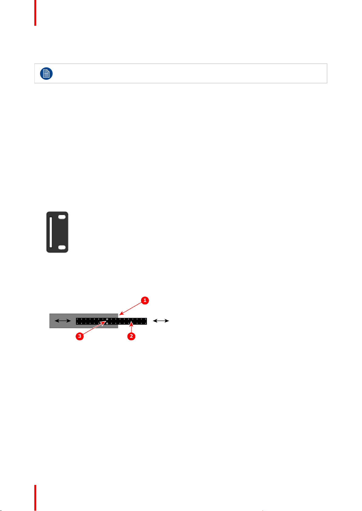
(and cable) weight within your rack. Use the following steps to properly adjust the side rails:
1. Measure and install the two supplied mounting brackets on your rear rack rails.
Image 3-2: Mounting bracket
2. Measure the distance between the front and rear rack rails. Remove the mounting screws that secure each
side rail to the chassis, and then adjust the spacing of each side rail as necessary. The ImagePRO–4K
uses two mounting screws on each side rail.
Image 3-3: ImagePRO–4K chassis with side rail and mounting screws
1. Chassis rear
2. Side rail
3. Mounting screws
3. Re-install the mounting screws. When properly adjusted, the end of each side rail will protrude through the
slot in the rear mounting bracket, once the chassis is rack mounted.
4. Lift the chassis, and while supporting it, slide the side rails through the slots in the rear mounting brackets.
5. While continuing to support the chassis, install and tighten the two lower screws.
6. Finally, install and tighten the two uppers screws in the rack rail.
Cable and adapter information
The table below provides information regarding cables used with the ImagePRO–4K. When connecting to an
ImagePRO–4K, use high-quality shielded cables.
18
R5906167 /00 ImagePRO–4K Video Processor
Page 19

General
Cable
RJ-45 Ethernet cable For use with external controllers or Web
AC power cord AC Power, 7 foot, 10A For power connection; 1
Description
Interface and EMTS GUI
Notes
For remote connections;
customer supplied
cord supplied
Power cord and line voltage selection
The ImagePRO–4K is rated to operate with the following specifications:
• Input Power: 100-240 VAC, 50-60 Hz
• Power Consumption: 2A maximum
The ImagePRO– 4K performs line voltage selection automatically. No user controls are required. The AC
power cords must be accessible so that they can be removed during field servicing.
WARNING: When used above 230 volts, a UL listed line cord rated for 250 volts at 15 amps must
be used and must conform to IEC-227 and IEC-245 standards. This cord will be fitted with a tandem
prong-type plug.
The rear panel ON/OFF switch does not disconnect the unit from input AC power. To facilitate
disconnection of AC power, the power cord must be connected to an accessible outlet near the unit.
Building Branch Circuit Protection: For 115 V use 20 A. For 230 V use 8 A.
R5906167 /00 ImagePRO–4K Video Processor
19
Page 20

General
20
R5906167 /00 ImagePRO–4K Video Processor
Page 21

Hardware Orientation
About this chapter
This chapter explains the ImagePRO–4K video processor’s hardware in detail.
Overview
•
Front panel
• Rear panel
4
R5906167 /00 ImagePRO–4K Video Processor
21
Page 22
Hardware Orientation
4.1 Front panel
About the front panel
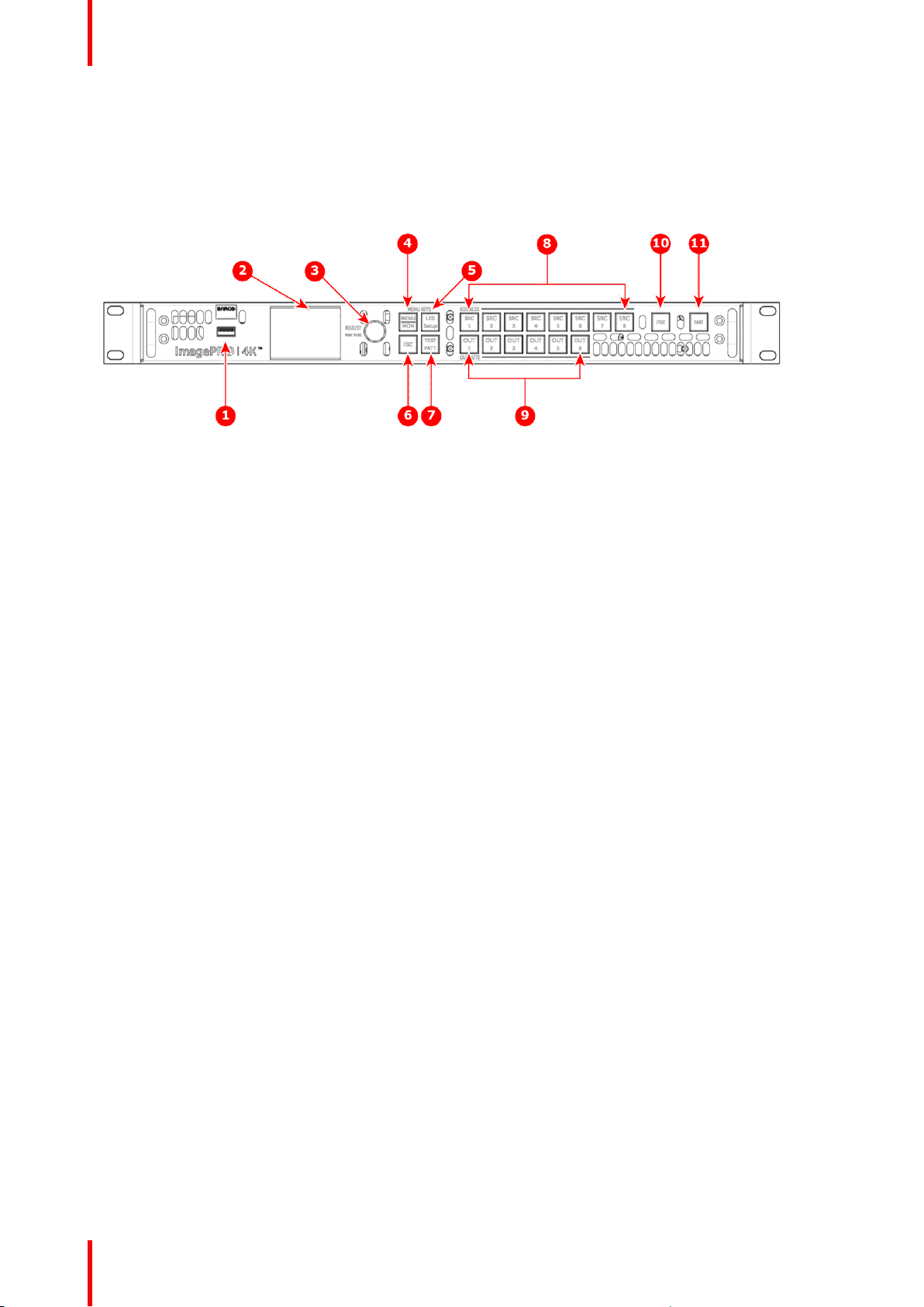
See Image 4-1 for an illustration of the ImagePRO–4K front panel.
Image 4-1: Front panel
1. USB port
2. Display screen
3. Adjust knob
4. Menu/Monitor mode toggle button
5. LED setup button
6. Escape button
Following are descriptions of each front panel control feature:
1. USB port
The USB port supports uploading and downloading system configurations and upgrading ImagePRO–4K
firmware.
2. Display screen
The LCD color video display shows all ImagePRO-4K menus, sub-menus, and messages. The display can
be toggled between Menu mode and Monitor mode.
3. Adjust knob
• Turn the Adjust knob to scroll up or down through the menus.
- Turn the knob clockwise to scroll down.
- Turn the knob counter-clockwise to scroll up.
• Press the Adjust knob to select menu items.
4. Menu/Monitor mode toggle button
The Menu/Monitor mode toggle button toggles the display between Menu mode and Monitor mode.
5. LED setup button
The LED setup button accesses the Setup Menu.
6. ESC (Escape) button
Press the ESC button to exit a menu without making changes, to cancel an operation, to answer No to
menu queries, or to return to the Status Menu. Each press takes you back up the menu tree one level.
7. Test pattern button
The Test pattern button sets up a test pattern on the selected output.
8. Source buttons: SRC 1 through SRC 8
Source buttons 1 through 6 default to the input sources on the Tri-Combo input card; SRC 7 defaults to
“Matte”; and SRC 8 defaults to “Logo.” All of the source buttons can be re-mapped, and they can be
mapped as Presets.
9. Output buttons: OUT 1 through OUT 6
Output buttons 1 through 6 default to the outputs on the Tri-Combo output card. OUT 1 is mapped as Aux
Channel A, OUT 2 as Aux Channel B. OUT 3 – 6 are not mapped.
10.FRZ (Freeze) button
FRZ (FREEZE) enables you to freeze a displayed image.
11. Take button
The Take button executes transitions in Preview mode.
7. Test pattern button
8. Source buttons: SRC 1 through SRC 8
9. Output buttons: OUT 1 through OUT 6
10. Freeze button
11. Take button
22
R5906167 /00 ImagePRO–4K Video Processor
Page 23
4.2 Rear panel
About the rear panel
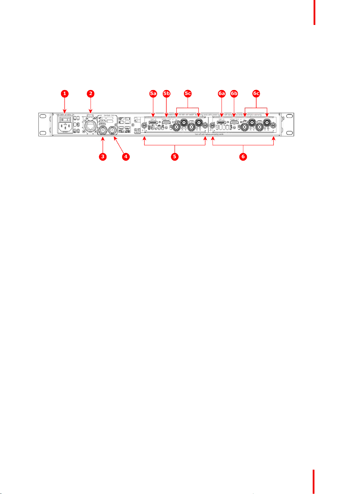
See Image 4-2 for an illustration of the ImagePRO–4K rear panel.
Image 4-2: Rear panel
Hardware Orientation
1. AC power
2. Ethernet port
3. BNC: Genlock In
4. BNC: Genlock Output
5. Tri-Combo input card
5a. DisplayPort 1.2
Following are descriptions of each rear-panel control feature:
1. AC power
A single AC connector with a power switch connects the ImagePRO–4K to your facility’s AC power source
through the supplied power cord. The integral switch turns the unit on and off.
100-240 VAC, 50/60Hz, 125w
2. Ethernet port
One RJ-45 connector provides 1000/100/10 Mbps Ethernet communications with the ImagePRO–4K. Use
the Ethernet port for running the Web Interface, for diagnostics, and for connection to an external device.
The Ethernet connector is compatible with:
• Standard RJ-45 Ethernet cables
• Neutrik EtherCon® series cables
3. BNC: Genlock In
Genlock analog reference input is through a BNC connector with fixed 75 ohm termination and supports
Blackburst and Bi-level at SD and supports Tri-level at HD.
4. BNC: Genlock Output
An internal sync generator, capable of Bi-level and Tri-level sync signals, provides Genlock reference
output, which is capable of Bi-level and Tri-level sync signals.
5. Tri-Combo input card:
a) DisplayPort 1.2.
b) HDMI 2.0.
c) SDI 1 through SDI 4.
This card provides one 20-pin DisplayPort connector, supporting DisplayPort video signal; one 19-pin
HDMI connector, supporting an HDMI video signal; and 4 BNC connectors, supporting Single Link and
Quad Link signals, in SD, HD, 3G, 6G, and 12G SDI formats.
The features of this card include:
• Up to six (6) independent signals.
• One channel of DisplayPort video on a full-size DisplayPort connector.
• One channel of HDMI video on a Type A connector.
• Up to four independent SDI signals with support for SD, HD, 3G, 6G, and 12G in Single Link or Quad
Link (3G).
• An LED on each input channel that turns green when a valid sync is detected.
6. Tri-Combo output card:
a) DisplayPort 1.2.
5b. HDMI 2.0
5c. SDI 1 through SDI 4
6. Tri-Combo output card
6a. DisplayPort 1.2
6b. HDMI 2.0
6c. SDI 1 through SDI 4
R5906167 /00 ImagePRO–4K Video Processor
23
Page 24

Hardware Orientation
b) HDMI 2.0.
c) SDI 1 through SDI 4.
This card provides one 20-pin DisplayPort connector, supporting DisplayPort video signal; one 19-pin
HDMI connector, supporting an HDMI video signal; and 4 BNC connectors, supporting Single Link and
Quad Link signals, in SD, HD, 3G, 6G, and 12G SDI formats.
The features of this card include:
• Up to six (6) independent signals.
• One channel of DisplayPort video on a full-size DisplayPort connector.
• One channel of HDMI video on a Type A connector.
• Up to four independent SDI signals with support for SD, HD, 3G, 6G, and 12G in Single Link or Quad
Link (3G).
Specifications of input and output video connections
On the system’s rear panel, each of the input and output connectors maps to a corresponding source or output
button on the front panel.
DisplayPort specifications
• DisplayPort per 1.2 specification
• Pixel clock up to 620 MHz
- Max pixel clock at 24 bits/pixel = 620 Mpix/sec
- Max pixel clock at 30 bits/pixel = 576 Mpix/sec
- Max pixel clock at 36 bits/pixel = 480 Mpix/sec
• Supported formats
- Formats up to 4096x2160@60 (30 bits)
- 4K/UHD supported:
◦ 3840x2,400/ 50/59.94/60 via 1x DP
◦ 4096x2,160/ 50/59.94/60 via 1x DP
◦ 3840x2,160/ 50/59.94/60 via 1x DP
• Supply up to 500 mA @ 3.3V on pin 20
- Allows the DP connector to power an external device.
- Overcurrent protection provided by means of an auto re-settable fuse.
• Multi-Stream Transport (MST)—not supported
• EDID version 1.3 compatible
• HDCP version 1.3 compatible
HDMI specifications
• HDMI per 2.0 specification
• Pixel clock up to 600 MHz
- Max pixel clock at 24 bits/pixel = 600 Mpix/sec
- Max pixel clock at 30 bits/pixel = 480 Mpix/sec
- Max pixel clock at 36 bits/pixel = 400 Mpix/sec
• Supported formats:
- Formats up to 2560x1600@60 and 3840x1200@60 (30 bits)
- 4K/UHD supported:
◦ 3840x2400/ 50/59.94/60 input via 1x HDMI
◦ 4096x2160/ 50/59.94/60 input via 1x HDMI
◦ 3840x2160/ 50/59.94/60 input via 1x HDMI
• EDID version 1.3 compatible
• HDCP version 1.4 and version 2.2 compatible
SDI specifications
• Supported formats:
24
R5906167 /00 ImagePRO–4K Video Processor
Page 25

Hardware Orientation
Signal
type
SD 1 4 SMPTE 259M-C 480i, 576i (NTSC/PAL)
HD 1 4 SMPTE 292M 1920x1080 @ 59.94i/50i
3G 1 4 SMPTE 424M
6G 1 1 SMPTE 2081-10 3840x2160 @ 23.98/24/25/29.97/30
12G 1 1 SMPTE 2082-10 3840x2160 @ 50/59.94/60
4K /
UHD
4K /
UHD
Min. BNC
connec-
tor
number
4 1 SMPTE 292M
4 1 SMPTE 424M
Max
channels
per card
Standard
Barcolink
SMPTE 2048-2
SMPTE 2048-2
Examples
1920x1080psf @ 23.98/24/25/29.97/30
720x480 @ 60p/50p
1920x1080 @ 60p/50p
1920x1200 @ 60p/50p
4096x2160 @ 23.98/24/25/29.97/30
4096x2160 @ 50/59.94/60
Image mapping: Quadrants
3840x2160 @ 23.98/24/25/29.97/30 as 4x HDSDI
4096x2160 @ 23.98/24/25/29.97/30 as 4x HDSDI
Image mapping: Quadrants
3840x2160 @ 50/59.94/60 as 4x 3G-SDI
4096x2160 @ 50/59.94/60 60 as 4x 3G-SDI
Level A and B supported
4K /
UHD
4 1 SMPTE ST 425-5 Image mapping: 2 Sample Interleave
Subdivision (2SI)
3840x2160 @ 23.98/24/25/29.97/30 as 4x HDSDI
4096x2160 @ 23.98/24/25/29.97/30 as 4x HDSDI
3840x2160 @ 50/59.94/60 as 4x 3G-SDI
4096x2160 @ 50/59.94/60 60 as 4x 3G-SDI
Level A and B supported
Genlock input connector
The genlock input supports NTSC and PAL Blackburst, as well as SD bi-level and HD tri-level sync signals,
per SMPTE 274M and SMPTE 296M.
When the ImagePRO– 4K is genlocked and the lock source is lost for some reason, the output of the unit
automatically switches to a “coasting” state without any discernible “glitching” on the output display device.
The user interface still indicates that the genlock source is “Lock to External.” The system does not, however,
automatically relock to the external source. The user must reselect Lock to External. This prevents constant
glitching of the outputs if the genlock source is not stable.
Once the genlock source is restored, the user can then re-select Lock to External to re-lock to the external
source.
Selecting Lock to External may cause the outputs to temporarily glitch, while the system is
synchronizing to the new source. If the genlock source has been permanently removed, it is
advisable to manually switch the system to Freerun to ensure a stable output.
Any time genlock settings are changed, there is a chance of a momentary glitch to the outputs.
R5906167 /00 ImagePRO–4K Video Processor
25
Page 26

Hardware Orientation
26
R5906167 /00 ImagePRO–4K Video Processor
Page 27

Setup and operation 5
About this chapter
This chapter describes how to quickly set up and begin operating your system, follow the steps in this section.
Links are provided to the appropriate sections in this guide, if you require more information.
Overview
Rear-panel connections
•
• Front-panel operation
• Factory reset
R5906167 /00 ImagePRO–4K Video Processor
27
Page 28
Setup and operation
5.1 Rear-panel connections
Refer to “Rear panel”, page 23 for the location of the power, input, and output connections and for
the location of the power switch.
Rear panel
1. Connect power—Ensure that power is properly connected to the ImagePRO–4K video processor.
2. Connect inputs—Connect all input sources to the ImagePRO–4K.
3. Connect outputs—Connect the output(s) on the ImagePRO–4K to your projector(s) or other target
devices.
4. Turn on power—Turn on power to the ImagePRO–4K, your connected display devices, and to all
peripheral equipment.
5.2 Front-panel operation
Front-panel features
Refer to “Front panel”, page 22 for the location and description of the front-panel features.
Image 5-1: ImagePRO–4K front panel
Display screen
The display screen is a 45 mm by 35 mm LED screen that displays the status of the system and the menus
and submenus of the system. The display screen can also monitor the input to or the output from the system.
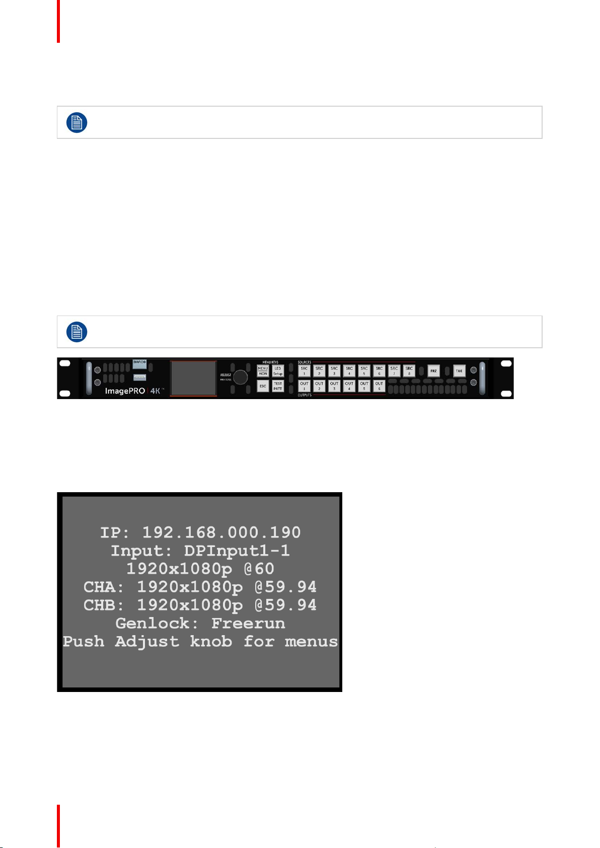
At power-up, the display screen displays the status of the system.
Image 5-2: Display screen showing status
Push the Adjust knob to enter the Setup menu.
28
R5906167 /00 ImagePRO–4K Video Processor
Page 29
Setup and operation
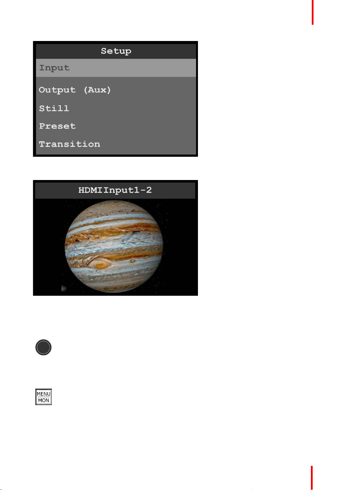
Image 5-3: Display screen showing Setup menu
Push the MENU/MON menu key to toggle the display screen between menu mode and monitor mode.
Image 5-4: Display screen monitoring HDMI input
Display screen controls
The display-screen controls include the adjust knob and the menu keys: MENU/MON, LED Setup, ESC, and
TEST PATT.
Adjust knob
1. Press the Adjust knob to enter the Setup menu.
2. Turn the Adjust knob to scroll up or down through the menus.
• Turn the knob clockwise to scroll down.
• Turn the knob counter-clockwise to scroll up.
3. Press the Adjust knob to select menu items.
MENU/MON key
1. Press the MENU/MON menu key to toggle between menu mode, in which the display screen
shows the menus, and monitor mode, in which the display monitors either input or output.
The system has two types of monitor: it can monitor the output, or it can monitor the input. If
an output button is amber, the system is monitoring that output. If the output buttons are
green, the system is monitoring input.
R5906167 /00 ImagePRO–4K Video Processor
29
Page 30

Setup and operation
LED Setup key
1. Press the LED Setup menu key to enter the LED Setup.
2. Scroll through the LED Setup menu to select the Aux channel, the wall sizing, and the image
sizing.
3. Select Save All to save your settings.
TEST PATT key
1. Press the TEST PATT menu key to enter the Test Pattern menu.
2. Scroll through the Test Pattern menu to select the Aux channel and the type of test pattern
and to set the AOI Raster Box, the Output Raster Box, and the Diagonal Motion on or off.
The test-pattern types are:
• Off
• Horizontal Ramp
• Vertical Ramp
• 100% Color Bars
• 16x16 Grid
• 32x32 Grid
• Burst
• 75% Color Bars
• 50% Gray
• Horizontal Steps
• Vertical Steps
• White
• Black
• SMPTE Bars
• H Alignment
• V Alignment
• HV Alignment
• Circle Alignment
• Red
• Green
• Blue
30
R5906167 /00 ImagePRO–4K Video Processor
Page 31
Setup and operation
• SMPTE Bars can be used to determine if the signal chain has a full or reduced range.
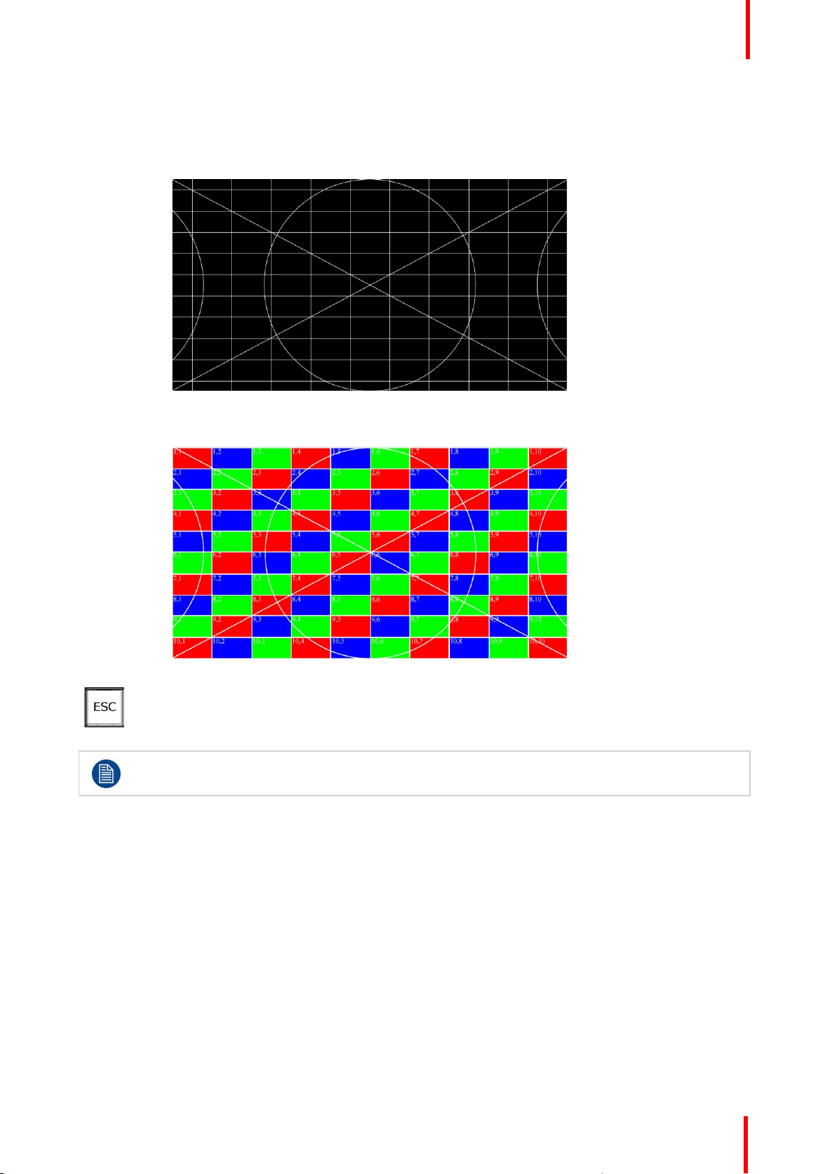
• Circle Alignment can be used to determine if the signal chain is horizontally or vertically
scaled. The horizontal and vertical grid spacing, grid color, grid orientation, and grid width can
all be adjusted.
Image 5-5: Circle Alignment test pattern
Circle Alignment also has an LED mode.
Image 5-6: Circle Alignment test pattern in LED mode
ESC key
1. Press the ESC (escape) menu key to deactivate a selection, to move back one level in a
menu, or to exit a menu.
Press the Adjust knob to enter the Setup menu.
1. Factory reset—If you are using the ImagePRO–4K for the first time, or if you are using an ImagePRO–4K
that has just returned from another event, perform a full factory reset to restore default system
configurations.
Press the Adjust knob to enter the Setup menu, then select Reset / Factory on the display screen. Reset /
Soft Reset keeps the user settings.
2. Native Rate—On the front panel, press the Adjust knob to enter the Setup menu, then select Setup /
System menu and select the desired Native Rate.
The Native Rate should be set to the frame rate in frames per second of the main output.
3. Assign primary output—If the primary output is DP, proceed to the next step.
If your primary output is HDMI/SDI, go to Setup / Output (AUX) / Primary Output and update the primary
output.
4. Adjust output format—Go to Setup / Output (AUX) / Aux Adjustment and update the output format.
5. Test output—Turn on a test pattern, verify that you have an image, and make any necessary adjustments.
When complete, turn off the test pattern.
6. Position and adjust the image— Use the LED Setup Menu to position the image on the LED wall or other
display device, scale the image, adjust Pan and Zoom settings, and save your view.
R5906167 /00 ImagePRO–4K Video Processor
31
Page 32
Setup and operation
Note: The preceding step provides a reliable shortcut when your setup does not require complex
adjustments. Use this step instead of or in conjunction with steps 7 through 9.
7. Set and adjust inputs / sources— Select inputs / sources and make any necessary adjustments to color
balance, timings, and any other settings necessary.
8. Save input / source configurations— After adjusting an input / source, save the input /source
configuration.
Repeat steps 7 and 8 for each input / source.
9. Adjust and save system settings—Adjust system parameters such as Ethernet settings and HDCP
parameters.
10.Save All — Select Save All.
Save All is the last menu item on the Setup page. Save All writes system settings to non-volatile memory.
5.3 Factory reset
Perform a factory reset
If you are using the ImagePRO– 4K for the first time, or if you are using an ImagePRO– 4K that has just
returned from an event, perform a full factory reset (Reset / Factory) to restore default system configurations.
1. Press the Adjust knob to enter the Setup menu.
2. Turn the adjust knob to scroll to Reset.
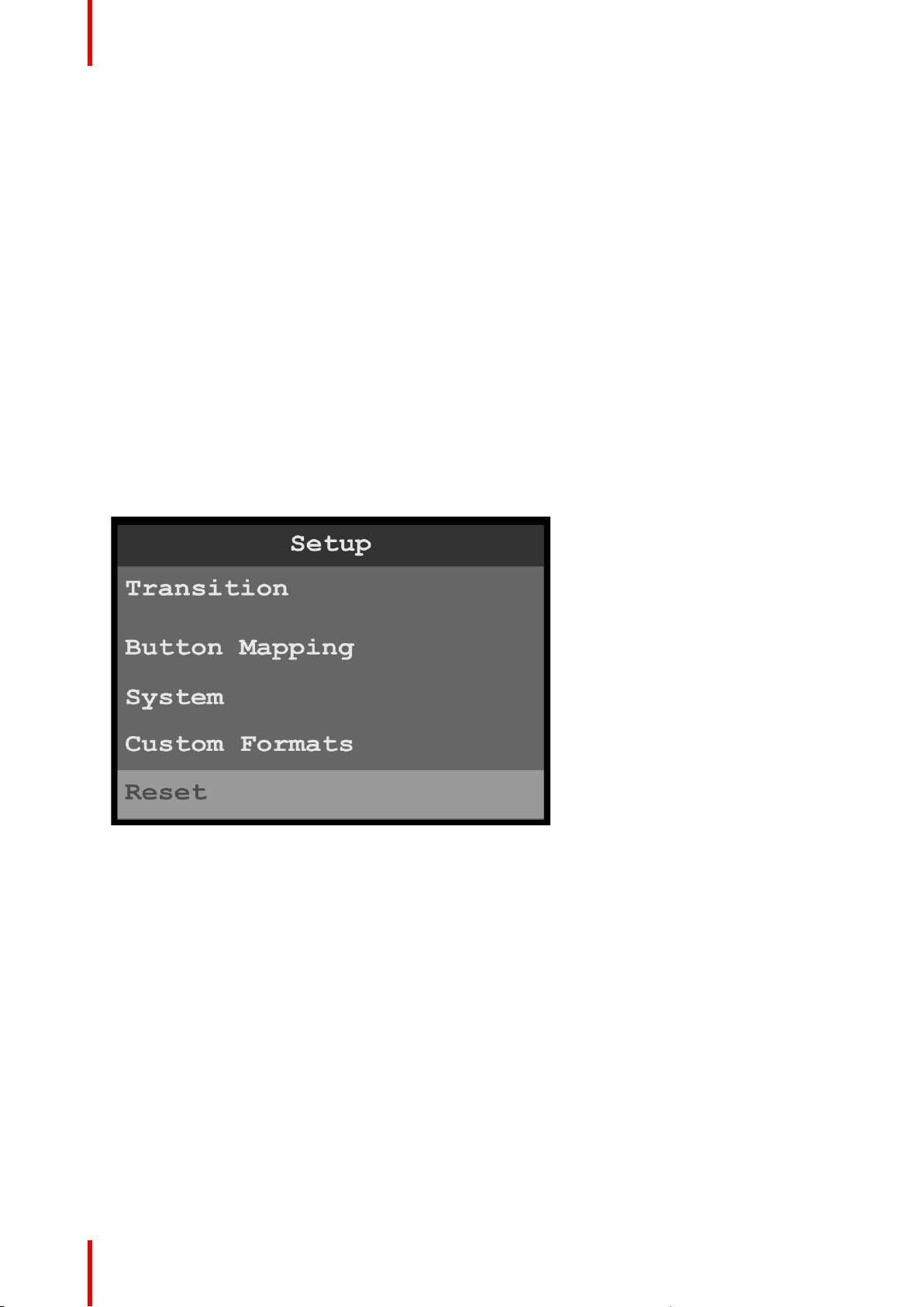
Image 5-7: Setup menu: Reset
3. Refer to “Reset menu”, page 95 for instructions on using the Reset menu.
32
R5906167 /00 ImagePRO–4K Video Processor
Page 33

Menu orientation 6
About this chapter
This chapter describes the ImagePRO–4K system menus, including how they are accessed and the functions
or parameters that are available. The principal menu trees are presented in block diagram format throughout
the chapter.
Overview
•
Power-up initialization
• ImagePRO–4K menus
• Input menu
• Output (Aux) menu
• Still menu
• Preset menu
• Button Mapping menu
• System menu
• Custom Formats
• Reset menu
• Firmware upgrade menu
• Tech Support menu
• Save All menu
R5906167 /00 ImagePRO–4K Video Processor
33
Page 34
Menu orientation
6.1 Power-up initialization
How to power up the ImagePRO–4K
Connect power to the ImagePRO– 4K, then locate the power switch on the rear panel and turn power On.
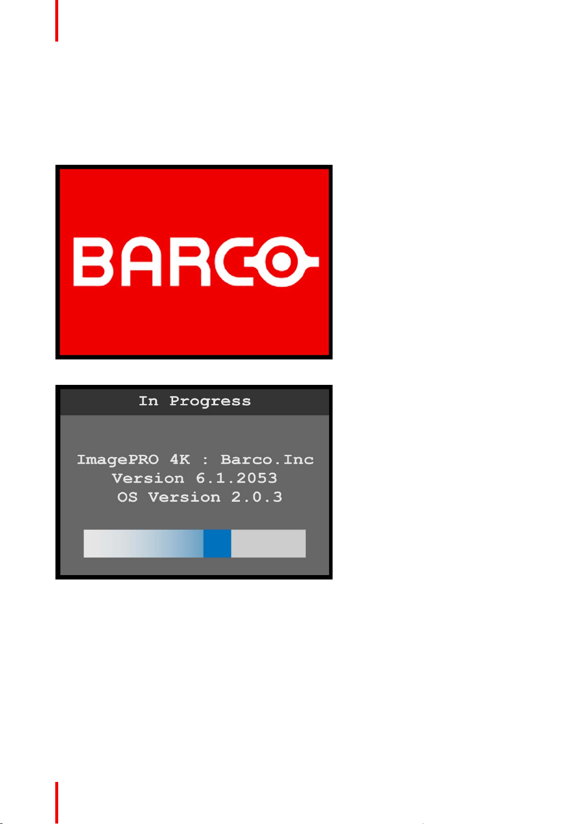
While the system is initializing, the front-panel buttons light up, and the Barco logo and the following
messages are displayed.
Image 6-1: Barco logo screen
Image 6-2: System initialization “In Progress”
The “In Progress” message shows the software version that is installed and the operating system version. This
version number changes as you install software upgrades.
When initialization is complete the ImagePRO–4K displays the status of the system.
34
R5906167 /00 ImagePRO–4K Video Processor
Page 35
Menu orientation
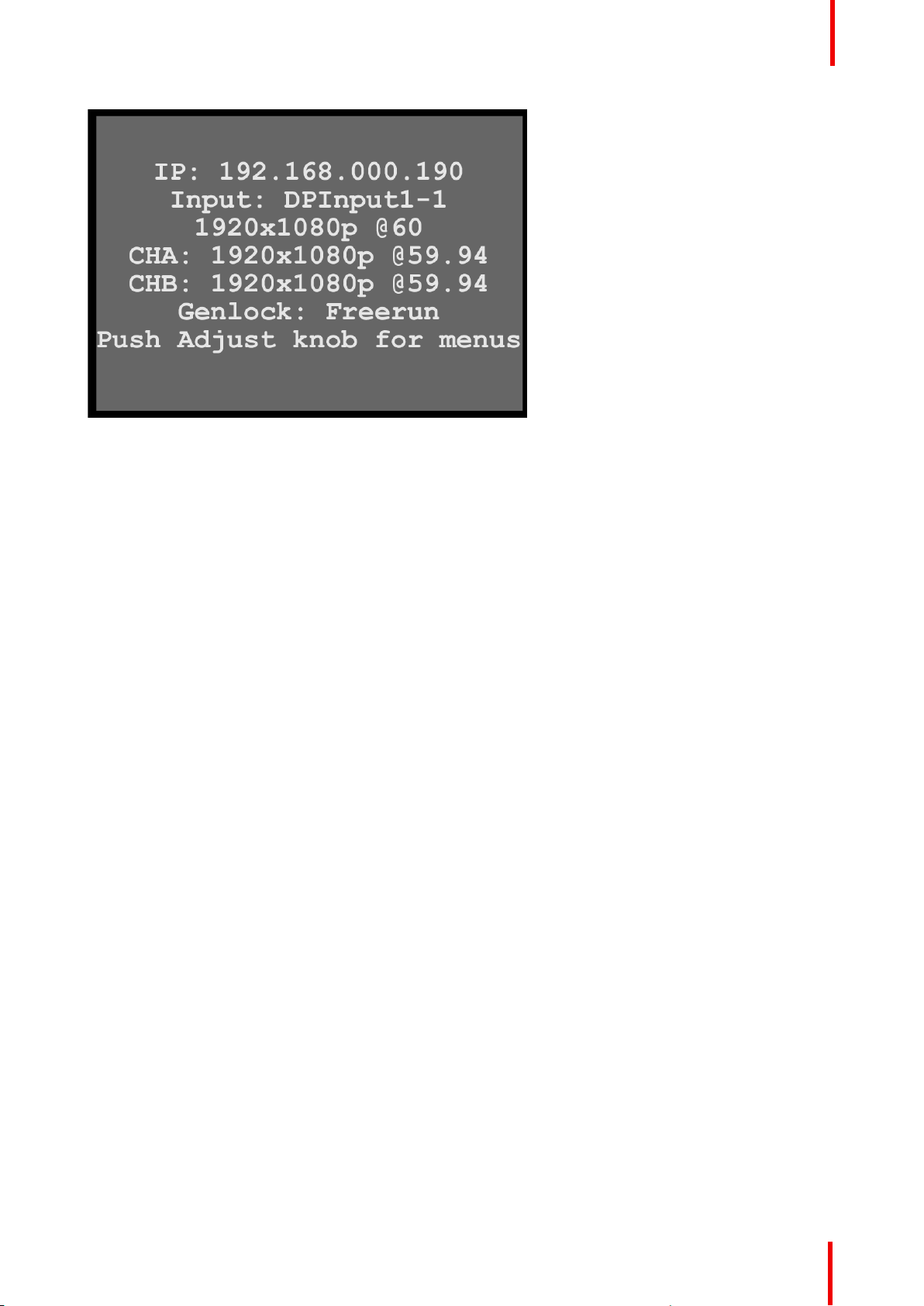
Image 6-3: System status
The status screen displays the IP address and the status of the inputs, output channels A and B, and the
Genlock status. The status screen also displays a message telling the user to push the Adjust knob to access
the menus.
6.2 ImagePRO–4K menus
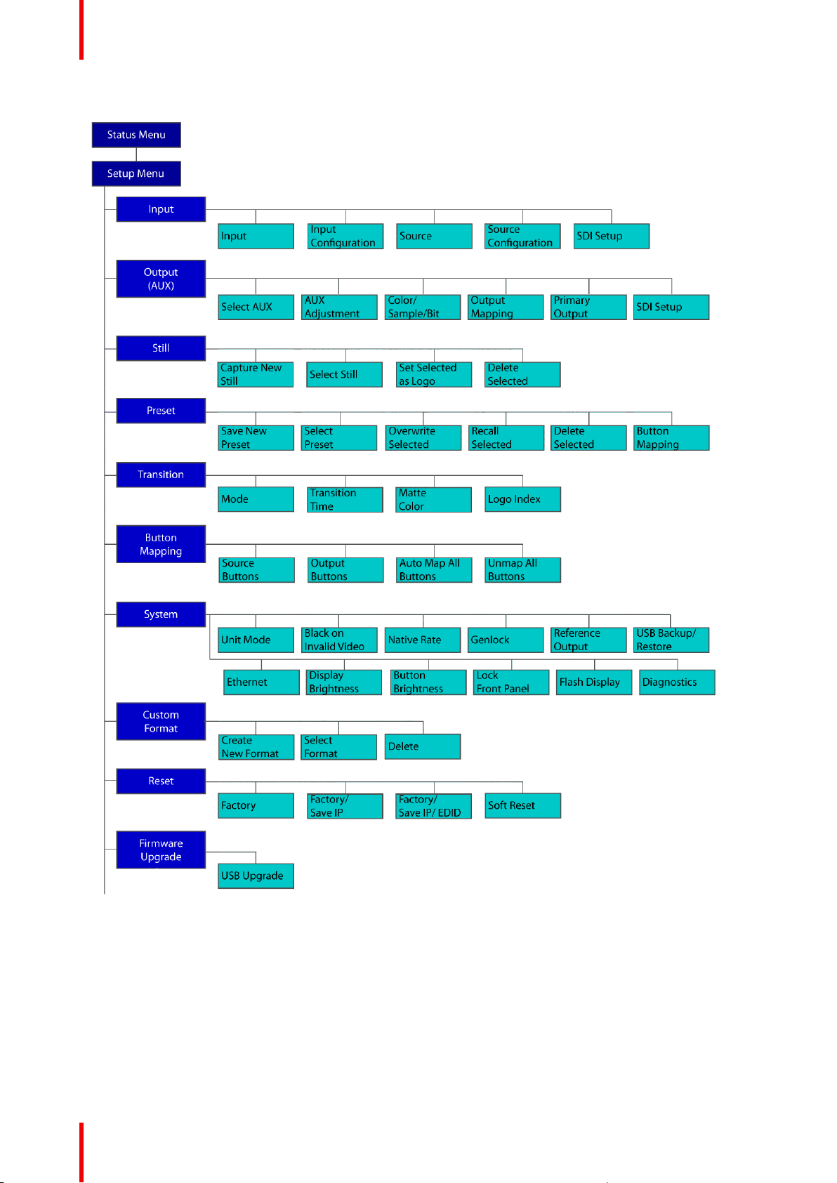
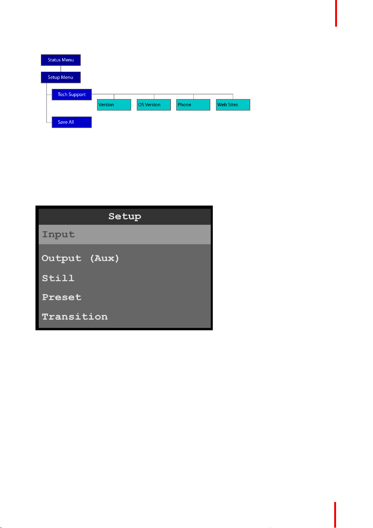
ImagePRO–4K menu tree
The diagram on the following pages illustrates the entire ImagePRO– 4K menu tree. Use this diagram for
reference as you learn how to operate the system.
R5906167 /00 ImagePRO–4K Video Processor
35
Page 36
Menu orientation
Image 6-4: Menu tree
36
R5906167 /00 ImagePRO–4K Video Processor
Page 37
Menu orientation
Image 6-5: Menu tree (Continued)
6.3 Input menu
General
This section provides information about setting up and using inputs. To enter the Input menu from the Setup
menu, scroll to and select Input.
Image 6-6: Setup menu: Input
Use the Input Menu to adjust all parameters relating to inputs. Using this menu, you can set all of the
configuration options for the selected input.
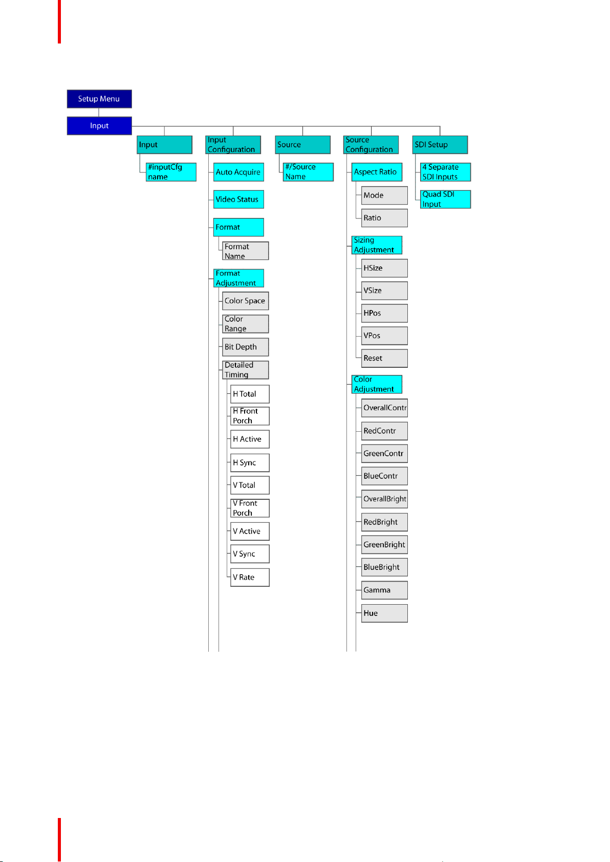
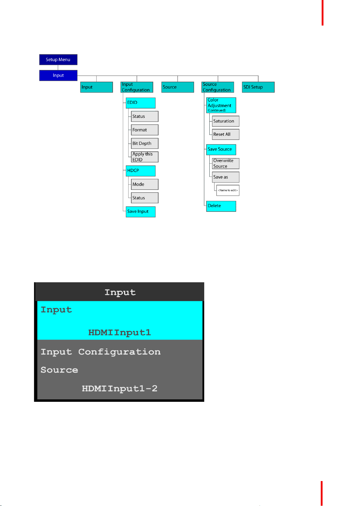
Input menu tree
Refer to Image 6-7 and Image 6-8 for an illustration of the Input menu tree.
R5906167 /00 ImagePRO–4K Video Processor
37
Page 38
Menu orientation
Image 6-7: Input menu tree
38
R5906167 /00 ImagePRO–4K Video Processor
Page 39
Menu orientation
Image 6-8: Input menu tree (Continued)
Input
1. Select Input on the Input menu.
Once Input is selected, the highlight bar turns from gray to cyan. Turning the adjust knob scrolls through
the available inputs.
2. Scroll to and select the input to be configured.
Image 6-9: Input selection
Input Configuration
1. Scroll to and select Input Configuration.
R5906167 /00 ImagePRO–4K Video Processor
39
Page 40
Menu orientation
Image 6-10: Input configuration
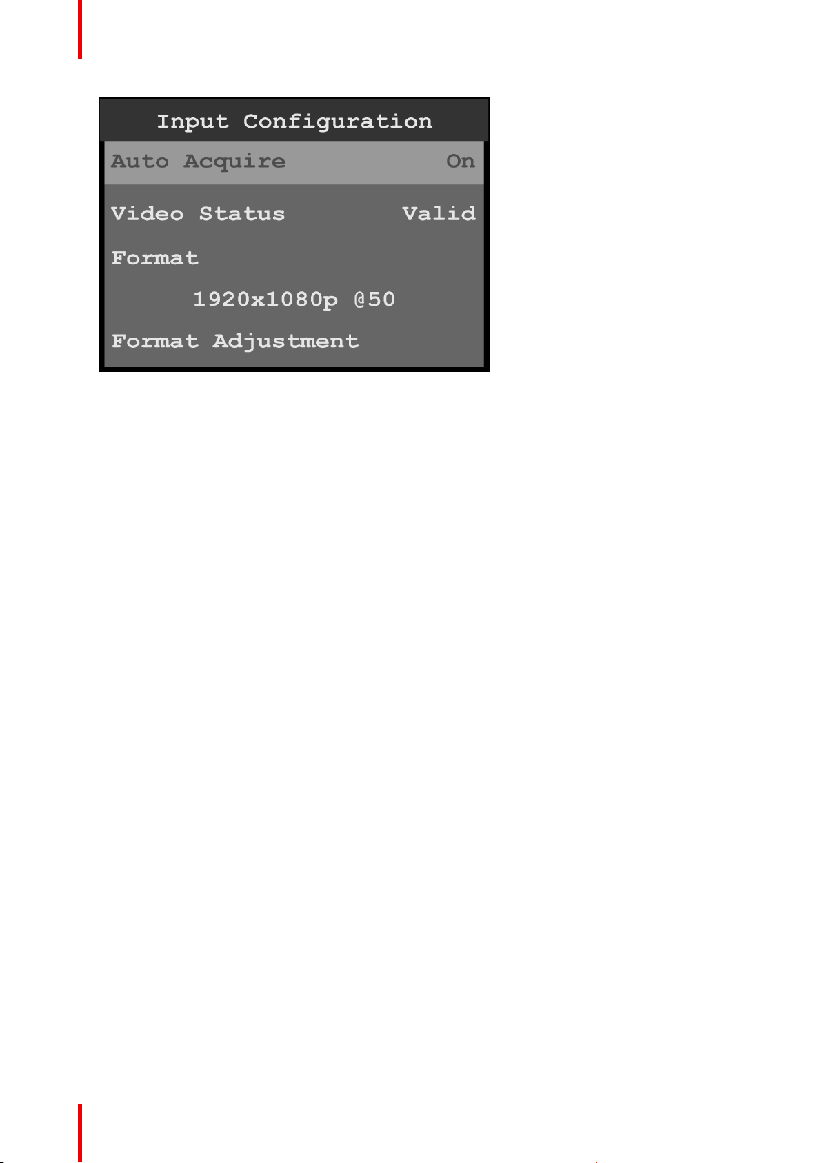
The Input Configuration screen displays the current system settings for Auto Acquire, Video Status, and
Format; and allows users to adjust the Format, EDID, and HDCP settings. Save Input allows users to save
the selected input settings.
2. Scroll to and select Auto Acquire.
• If Auto Acquire is On, the system detects and acquires the input type and resolution. Default is On.
• If Auto Acquire is Off, the input type and resolution must be selected.
3. If necessary, scroll to and select Format to adjust the resolution and refresh rate.
4. Scroll to and select Format Adjustment to view or adjust the Color Space, Color Range, Bit Depth, and
Detailed Timing.
The options for these adjustments are:
Color Space • RGB
• SMPTE
Color Range • Full Range
• Reduced Range
Bit Depth • 8, 10, or 12
Detailed Timing • H Total: Total pixel count per line
• H Front Porch: The offset between the end of the active area and the
beginning of H sync
• H Active: The horizontal size in pixels of the active area
• H Sync: H sync width in pixels
• V Total: Total line count per frame
• V Front Porch: The offset in lines between the end of the output active area
and the beginning of V sync
• V Active: The vertical size of the output active area
• V Sync: V sync width in lines
• V Rate: Vertical frame rate in frames per second
These are status and informational menus. No adjustments can be made on the
Detailed Timing screen.
40
R5906167 /00 ImagePRO–4K Video Processor
Page 41
Menu orientation
Image 6-11: Input configuration (Continued)
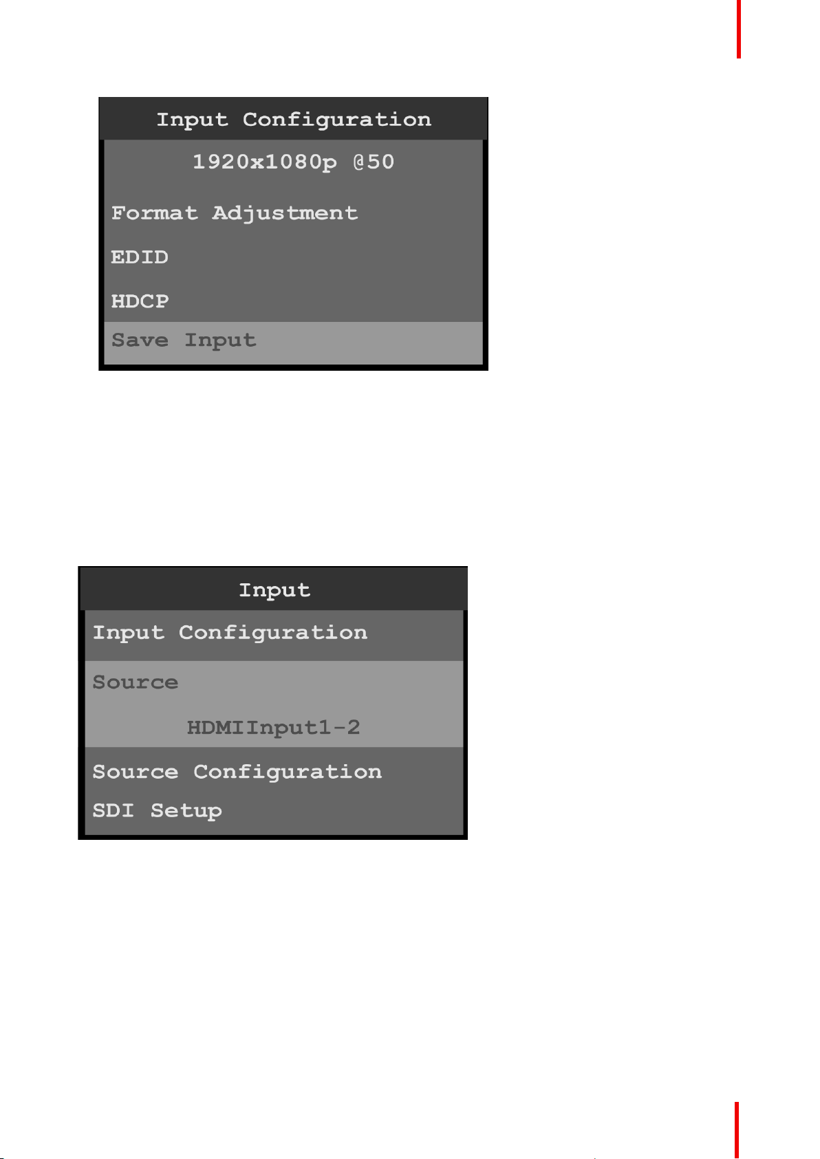
5. Scroll to and select EDID to set up and apply an EDID for the input.
EDID is not applicable to SDI inputs.
6. Scroll to and select HDCP to set up and apply HDCP settings for the input.
The default HDCP mode setting for DisplayPort, DVI, and HDMI is Off. HDCP Mode is not applicable to
SDI inputs.
7. Scroll to and select Save Input to save the selected input settings.
Source
The Input Source menu allows users to select from available source configurations for an input.
Image 6-12: Input Source
Source Configuration
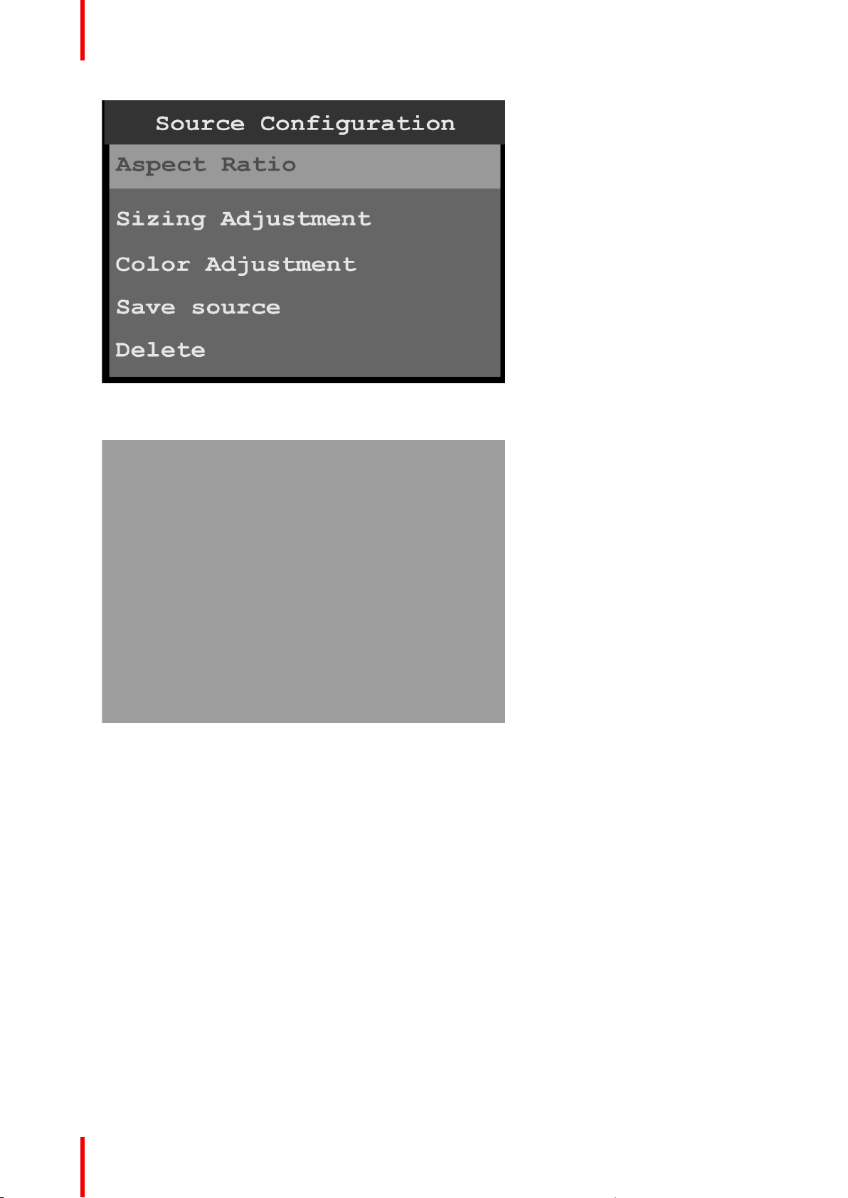
1. Scroll to and select Source Configuration on the Input menu to adjust the aspect ratio, sizing, and color of
the input source.
R5906167 /00 ImagePRO–4K Video Processor
41
Page 42
Menu orientation
Image 6-13: Source Configuration menu
2. Scroll to and select Aspect Ratio to adjust the aspect ratio of the input source.
Image 6-14: Source Configuration: Aspect Ratio
a) Use Mode to select the general aspect ratio of the input source.
The modes are:
• 3:1
• 16:9
• 16:10
• 3:2
• 4:3
• 5:4
• 1:1
• Custom
b) Use Ratio to adjust the ratio of the height of the input source to its width.
If, for example, the Mode is 3:1, the Ratio is 3.00. Turning the adjust knob counter-clockwise, users can
adjust the ratio to any custom setting, for example from 2.99 to 1.78. Setting the Ratio to 1.77 sets the
Mode to 16:9.
3. Scroll to and select Sizing Adjustment to adjust the H Size, V Size, H Pos, and V Pos of the input source.
Reset returns the sizing adjustments to their initial settings.
4. Scroll to and select Color Adjustment to adjust the following color aspects of the input source:
• Overall contrast – Range: 50 to 150; Default: 100
• Red contrast – Range: 50 to 150; Default: 100
• Green contrast – Range: 50 to 150; Default: 100
42
R5906167 /00 ImagePRO–4K Video Processor
Page 43
• Blue contrast – Range: 50 to 150; Default: 100
• Overall brightness – Range: 25 to 150; Default: 100
• Red brightness – Range: 25 to 150; Default: 100
• Green brightness – Range: 25 to 150; Default: 100
• Blue brightness – Range: 25 to 150; Default: 100
• Hue – Range: –90 to 90; Default: 0
• Gamma – Range: 0.30 to 3.30; Default: 1.00
• Saturation – Range: 0 to 150: Default: 100
• Reset returns the color adjustments to their initial settings.
5. Scroll to and select Save Source to save any adjusted source settings.
a) Overwrite Source overwrites the current source configuration with the adjusted settings.
b) Save As saves the adjusted settings to a new source configuration.
Source configurations are chosen from the from the Input Source menu.
6. Scroll to and select Delete to delete the currently selected source.
SDI Setup
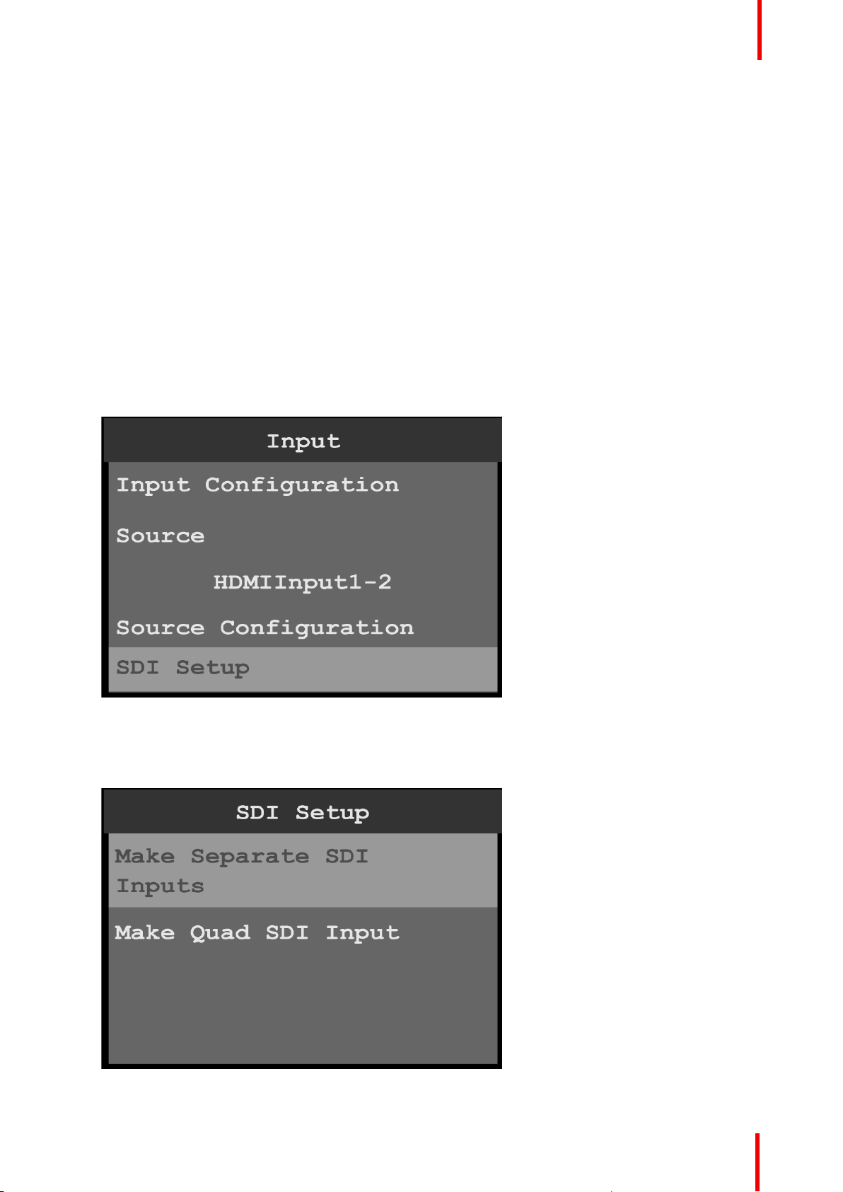
1. Scroll to and select SDI Setup on the Input menu to set up the SDI inputs.
Menu orientation
Image 6-15: Input menu: SDI Setup
SDI may be set up in two configurations:
• Four separate SDI inputs.
• A single Quad SDI input.
Image 6-16: SDI Setup
R5906167 /00 ImagePRO–4K Video Processor
43
Page 44
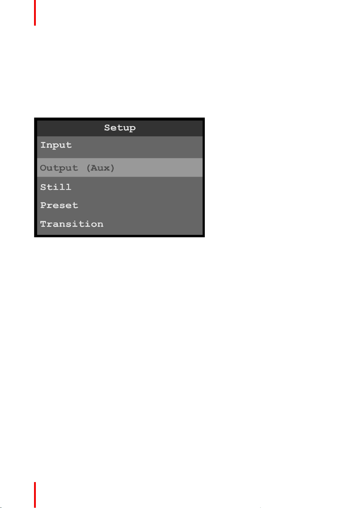
Menu orientation
2. Scroll to and select Make Separate SDI Inputs to create four separate SDI inputs.
3. Scroll to and select Make Quad SDI Input to create a single Quad SDI input.
6.4 Output (Aux) menu
General
This section provides information about setting up and using outputs (Auxes). To enter the Output (Aux) menu
from the Setup menu, scroll to and select Output (Aux).
Image 6-17: Setup menu: Output (Aux)
Use the Output (Aux) Menu to adjust all parameters relating to outputs (Auxes). Using this menu, you can set
all of the configuration options for the selected output (Aux).
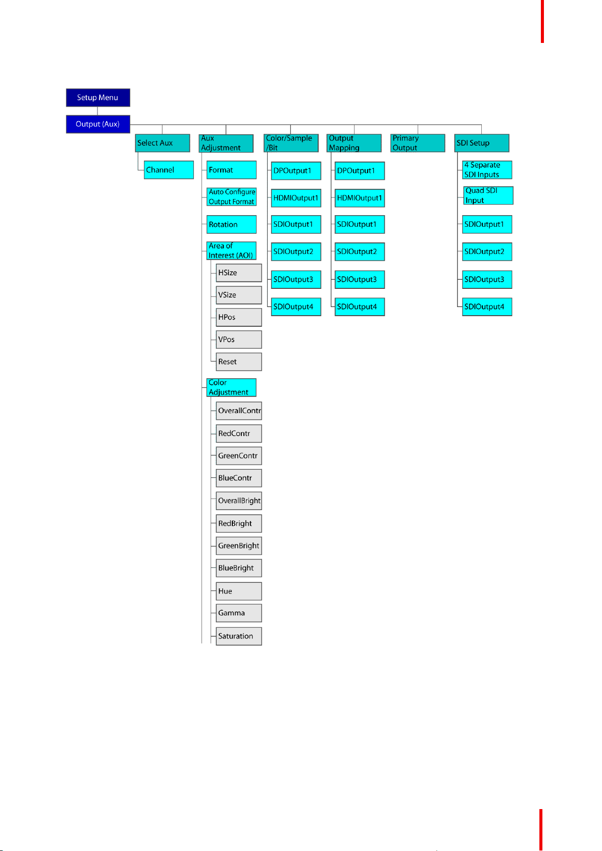
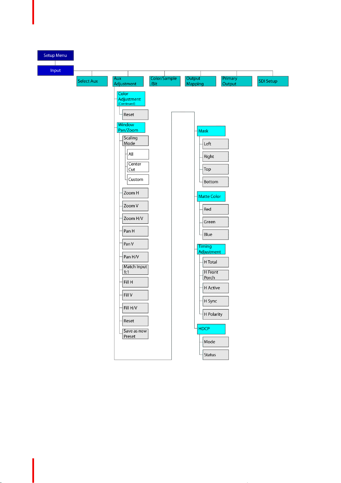
Output (Aux) menu tree
Refer to Image 6-18 and Image 6-19 for illustrations of the Output (Aux) menu tree.
44
R5906167 /00 ImagePRO–4K Video Processor
Page 45
Menu orientation
Image 6-18: Output (Aux) menu tree
R5906167 /00 ImagePRO–4K Video Processor
45
Page 46
Menu orientation
Image 6-19: Output (Aux) menu tree (Continued)
Select Aux
1. Select Select Aux on the Output (Aux) menu.
46
R5906167 /00 ImagePRO–4K Video Processor
Page 47
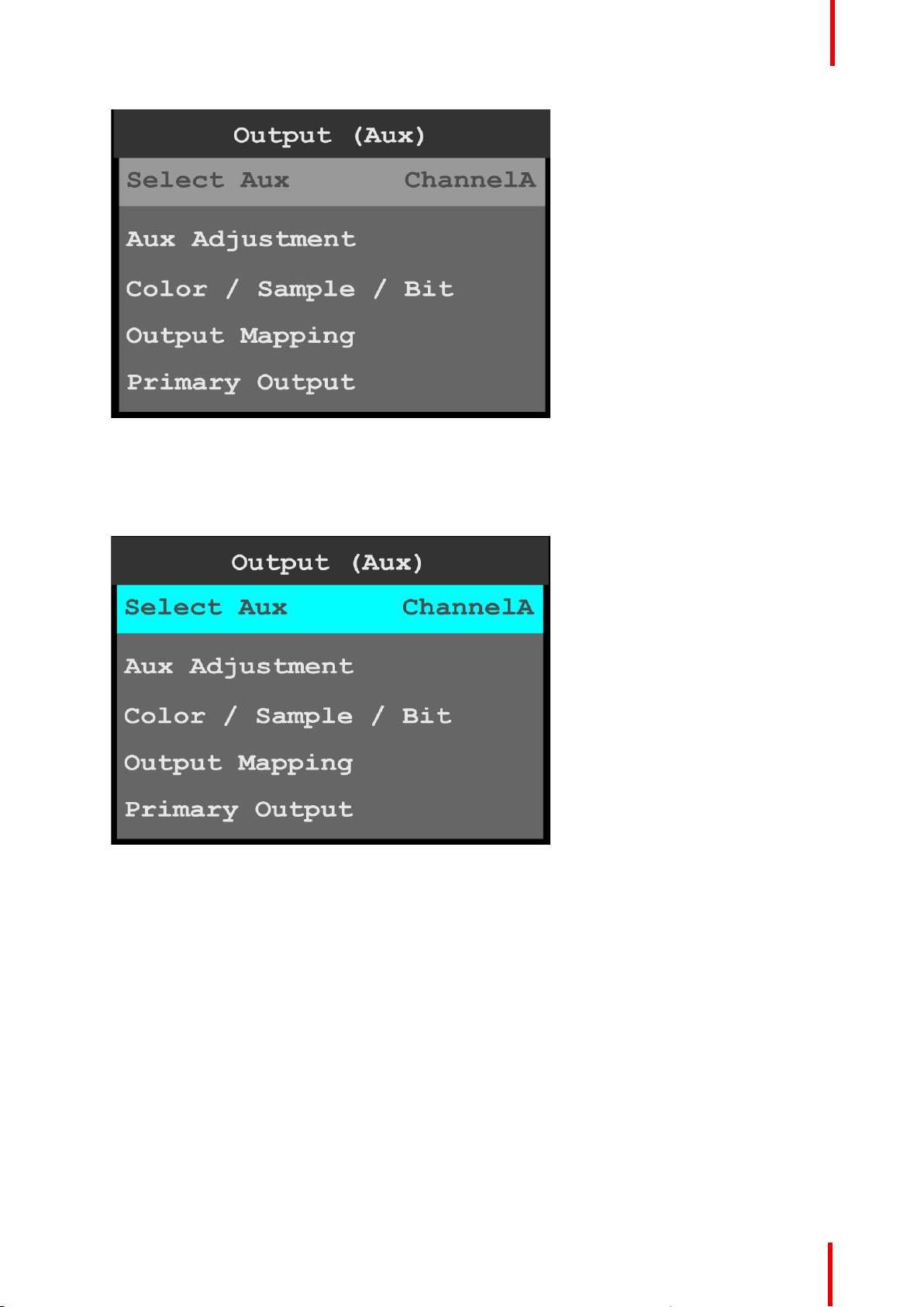
Menu orientation
Image 6-20: Output (Aux): Select Aux
Once Select Aux is selected, the highlight bar turns from gray to cyan. Turning the adjust knob scrolls
through the available channels.
2. Scroll to and select the channel to be configured.
ChannelA or ChannelB may be selected.
Image 6-21: Output (Aux): channel selection
Aux Adjustment
1. Scroll to and select Aux Adjustment.
The Aux Adjustment menu allows users to manually format the resolution and refresh rate, to auto
configure the output format, to rotate the output image, to adjust the area of interest (AOI), adjust the color,
to pan or zoom the window, create a mask, adjust the matte color, make timing adjustments, and select
HDCP settings.
2. Scroll to and select Format to adjust the resolution and refresh rate.
R5906167 /00 ImagePRO–4K Video Processor
47
Page 48
Menu orientation
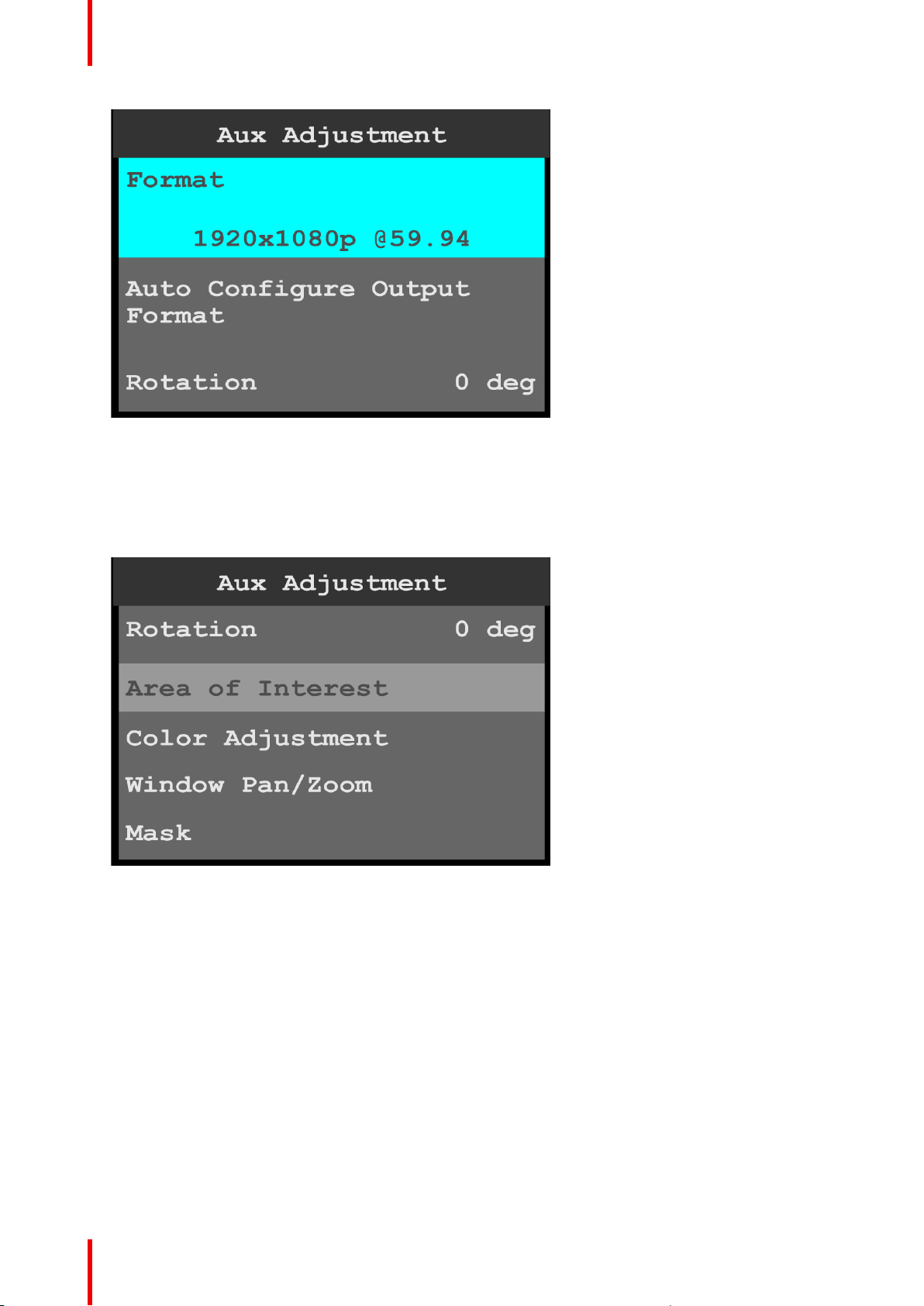
Image 6-22: Aux Adjustment: Format
3. Scroll to and select Auto Configure Output Format to auto-configure the output format.
4. Scroll to and select Rotation to rotate the selected Output (Aux) channel.
The rotation options are 0, 90, 180, and 270 degrees.
5. Scroll to and select Area of Interest to adjust the H Size, V Size, H Pos, and V Pos of the area of interest
(AOI).
Image 6-23: Aux Adjustment: Area of Interest
• H Size adjusts the horizontal size of the AOI.
• V Size adjusts the vertical size of the AOI.
• H Pos adjusts the horizontal position of the AOI.
• V Pos adjusts the vertical position of the AOI.
• Reset returns all adjustments to their initial settings.
6. Scroll to and select Color Adjustment to adjust the following color aspects of the output (Aux):
• Overall contrast – Range: 50 to 150; Default: 100
• Red contrast – Range: 50 to 150; Default: 100
• Green contrast – Range: 50 to 150; Default: 100
• Blue contrast – Range: 50 to 150; Default: 100
• Overall brightness – Range: 25 to 150; Default: 100
• Red brightness – Range: 25 to 150; Default: 100
• Green brightness – Range: 25 to 150; Default: 100
• Blue brightness – Range: 25 to 150; Default: 100
• Hue – Range: –90 to 90; Default: 0
48
R5906167 /00 ImagePRO–4K Video Processor
Page 49

Menu orientation
• Gamma – Range: 0.30 to 3.30; Default: 1.00
• Saturation – Range: 0 to 150: Default: 100
• Reset returns the color adjustments to their initial settings.
7. Scroll to and select Window Pan/Zoom to view or adjust panning and zooming options.
Scaling Mode can be set to All, Center Cut, or Custom. For custom configurations, other adjustments
can be made.
• Zoom H zooms in or out on the horizontal center of the image.
Increasing this setting “stretches” the image to the right and left along the horizontal plane. Decreasing
this setting brings the right and left edges in toward the center of the active area.
• Zoom V zooms in or out on the vertical center of the image.
Increasing this setting “stretches” the image up and down along the vertical plane. Decreasing this
setting brings the top and bottom edges in toward the center of the active area.
• Zoom H/V adjusts both horizontal and vertical zoom settings at the same time.
• Pan H moves the image to the left or right.
You can adjust Pan settings only after adjusting Zoom settings.
• Pan V moves the image up or down.
You can adjust Pan settings only after adjusting Zoom settings.
• Match Input 1:1 fills the AOI with the unscaled input image.
If you created an Area of Interest that is smaller than the default active area for the input, a portion of
the image is not displayed. You can then use the Pan settings to display the portion of the image you
want to show.
• Match Program matches the selected view in PVW to its corresponding layer in PGM.
• Reset restores the default settings.
8. Scroll to and select Mask to view or adjust masking options.
Scaling Mode can be set to All, Center Cut, or Custom. For custom configurations, other adjustments
can be made.
Custom Mask values are given in percentages, and range from 0% to 100%. The default mask value is
0%.
• Left masks the left edge of an image.
• Right masks the right edge of an image.
• Top masks the top of an image.
• Bottom masks the bottom of an image.
• Reset restores the default settings.
9. Scroll to and select Matte Color to view or adjust the matte-color options.
• Red – Range: 0 to 1023; default is 0.
• Green – Range: 0 to 1023; default is 0.
• Blue – Range: 0 to 1023; default is 0.
10.Scroll to and select Timing Adjustment to view and adjust the output timing options.
Note that users should be familiar with how the adjustments they are making may affect the video format.
The user should use a timing calculator to determine the correct numbers for timing. Incorrect settings can
cause unstable or asynchronous video output.
• H Total: Total pixel count per line.
• H Front Porch: The offset between the end of the active area and the beginning of H sync.
• H Active: The horizontal size in pixels of the active area.
• H Sync: H sync width in pixels.
• V Total: Total line count per frame.
• V Front Porch: The offset in lines between the end of the output active area and the beginning of V
sync.
• V Active: The vertical size of the output active area.
• V Sync: V sync width in lines.
• V Rate: Vertical frame rate in frames per second.
• Save as Custom Format saves the custom format, which can now be chosen from the Aux
Adjustment > Format menu.
11. Scroll to and select HDCP to set up and apply HDCP settings for the input.
The default HDCP mode setting for DisplayPort, DVI, and HDMI is Off. HDCP Mode is not applicable to
SDI inputs.
R5906167 /00 ImagePRO–4K Video Processor
49
Page 50
Menu orientation
Color/Sample/Bit
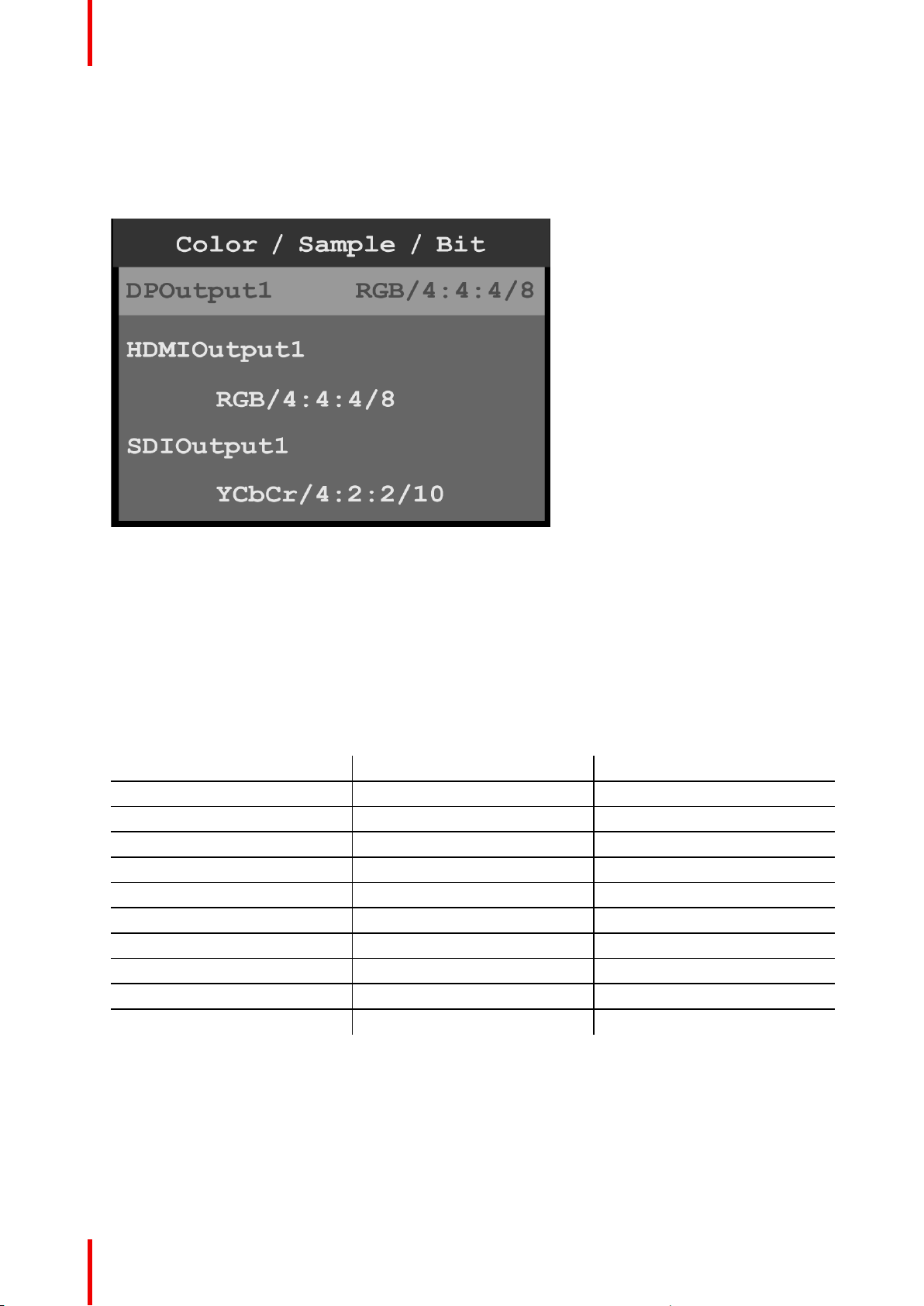
1. Scroll to and select Color / Sample / Bit to view and adjust the color space (RGB or YCbCr), sampling rate
(4:4:4), and bit depth (8, 10, or 12) of the output (Aux) signal.
The Color / Sample / Bit menu allows users to view and adjust the color space, sampling rate, and bit depth
of the output (Aux) signal.
Image 6-24: Output (Aux): Color / Sample / Bit
The Color / Sample / Bit menu displays the current color space, sampling rate, and bit depth settings of the
output (Aux) signal.
2. Scroll to and select DPOutput1.
Once the output is selected, the highlight bar turns from gray to cyan.
3. Turn the adjust knob to scroll through the possible color space, sampling rate, and bit depth settings for the
selected output.
4. Press the adjust knob to select the desired color space, sampling rate, and bit depth settings for the
selected output.
5. Repeat steps 2 through 4 for any desired output.
Color/Sample/Bit choices for DP, HDMI, and SDI are:
DP HDMI SDI
RGB/4:4:4/8 RGB/4:4:4/8 –
RGB/4:4:4/10 RGB/4:4:4/10 –
RGB/4:4:4/12 RGB/4:4:4/12 –
YCbCr/4:4:4/8 YCbCr/4:4:4/8 –
YCbCr/4:4:4/10 YCbCr/4:4:4/10 –
YCbCr/4:4:4/12 YCbCr/4:4:4/12 –
– YCbCr/4:2:2/12 –
– – YCbCr/4:2:2/10
– YCbCr/4:2:0/8 –
– YCbCr/4:2:0/10 –
Output Mapping
1. Scroll to and select Output Mapping to view and adjust the output channel (A or B) for any output.
2. Scroll to and select an output, for example HDMIOutput1.
Once the output is selected, the highlight bar turns from gray to cyan.
50
R5906167 /00 ImagePRO–4K Video Processor
Page 51
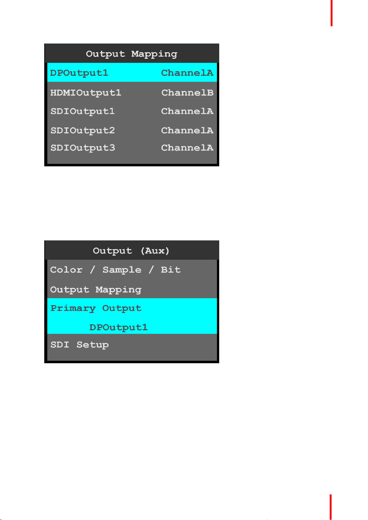
Image 6-25: Output (Aux): Output Mapping
3. Turn the adjust knob to scroll to either ChannelA or ChannelB.
4. Press the adjust knob to select the desired channel.
5. Repeat steps 2 through 4 for any desired output.
Menu orientation
Primary Output
1. Scroll to and select Primary Output to view and adjust the primary output.
Once the Primary Output is selected, the highlight bar turns from gray to cyan.
Image 6-26: Output (Aux): Primary Output
2. Turn the adjust knob to scroll through the outputs.
3. Press the adjust knob to select the desired output.
SDI Setup
1. Scroll to and select SDI Setup on the Output (Aux) menu to set up the SDI outputs.
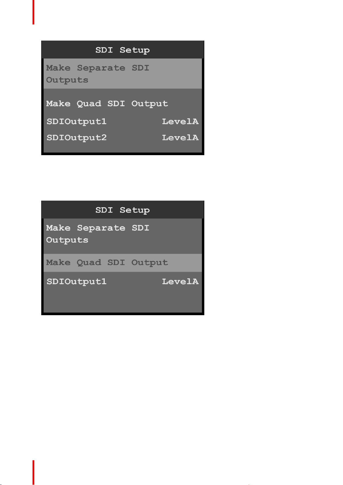
SDI may be set up in two configurations:
• Four separate SDI outputs.
If four separate outputs are created, each of the outputs can be individually configured to either Level A
or Level B.
• A single Quad SDI output.
If a single quad SDI output is created, that output can be configured to either Level A or Level B.
2. Scroll to and select Make Separate SDI Outputs.
R5906167 /00 ImagePRO–4K Video Processor
51
Page 52
Menu orientation
Image 6-27: SDI Setup: separate SDI outputs
3. If necessary, scroll to and select an individual SDI output, for example SDIOutput1.
Once an output is selected, the highlight bar turns from gray to cyan.
4. Use the adjust knob to scroll through the levels (A and B) and to select the desired level.
5. Scroll to and select Make Quad SDI Output.
Image 6-28: SDI Setup: quad SDI output
6. If necessary, scroll to and select the quad SDI output.
Once the output is selected, the highlight bar turns from gray to cyan.
7. Use the adjust knob to scroll through the levels (A and B) and to select the desired level.
6.5 Still menu
General
This section provides information about capturing and using stills. To enter the Still menu from the Setup
menu, scroll to and select Still.
52
R5906167 /00 ImagePRO–4K Video Processor
Page 53
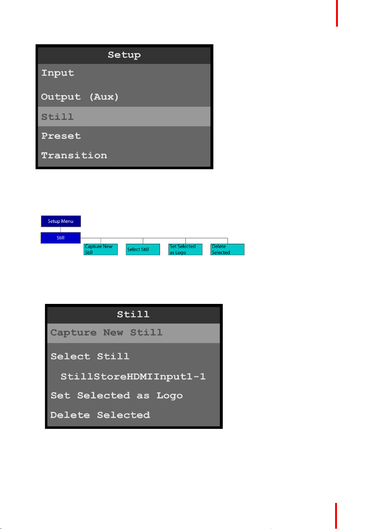
Image 6-29: Setup menu: Still
Still menu tree
Refer to Image 6-30 for an illustration of the Still menu tree.
Menu orientation
Image 6-30: Still menu tree
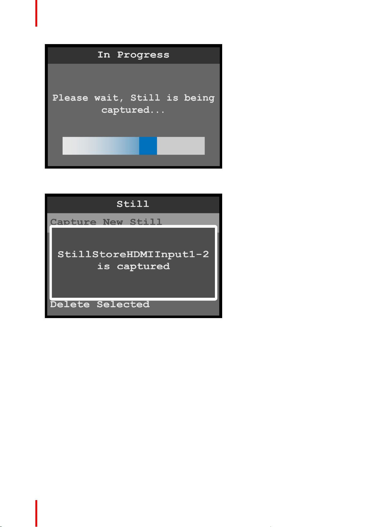
Capture New Still
1. Select Capture New Still on the Still menu.
Image 6-31: Setup menu: Still
The system displays a progress screen.
R5906167 /00 ImagePRO–4K Video Processor
53
Page 54
Menu orientation
Image 6-32: Still: In Progress
Once the still has been captured, the system displays a message that includes the name of the still.
Image 6-33: New Still captured
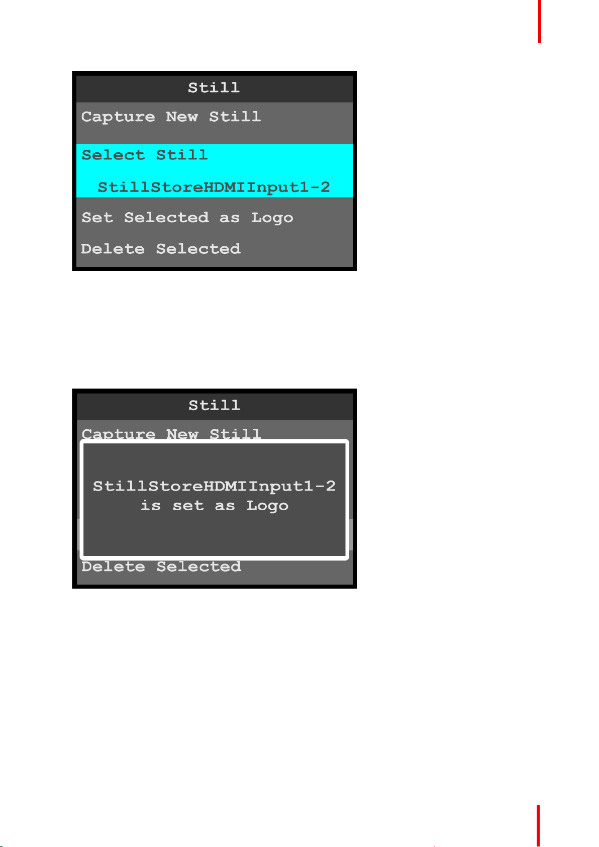
Select Still
1. Select Select Still on the Still menu.
Once the Select Still is selected, the highlight bar turns from gray to cyan.
54
R5906167 /00 ImagePRO–4K Video Processor
Page 55
Menu orientation
Image 6-34: Still menu: Select Still
2. Use the adjust knob to scroll through the stored stills and to select the desired still, for example
StillStoreHDMIInput1-2.
Set Selected as Logo
1. Select the still to be used as a logo.
2. Select Set Selected as Logo on the Still menu.
The system displays a message that says that the selected still has been set as a logo.
Image 6-35: Still menu: Still Set as Logo
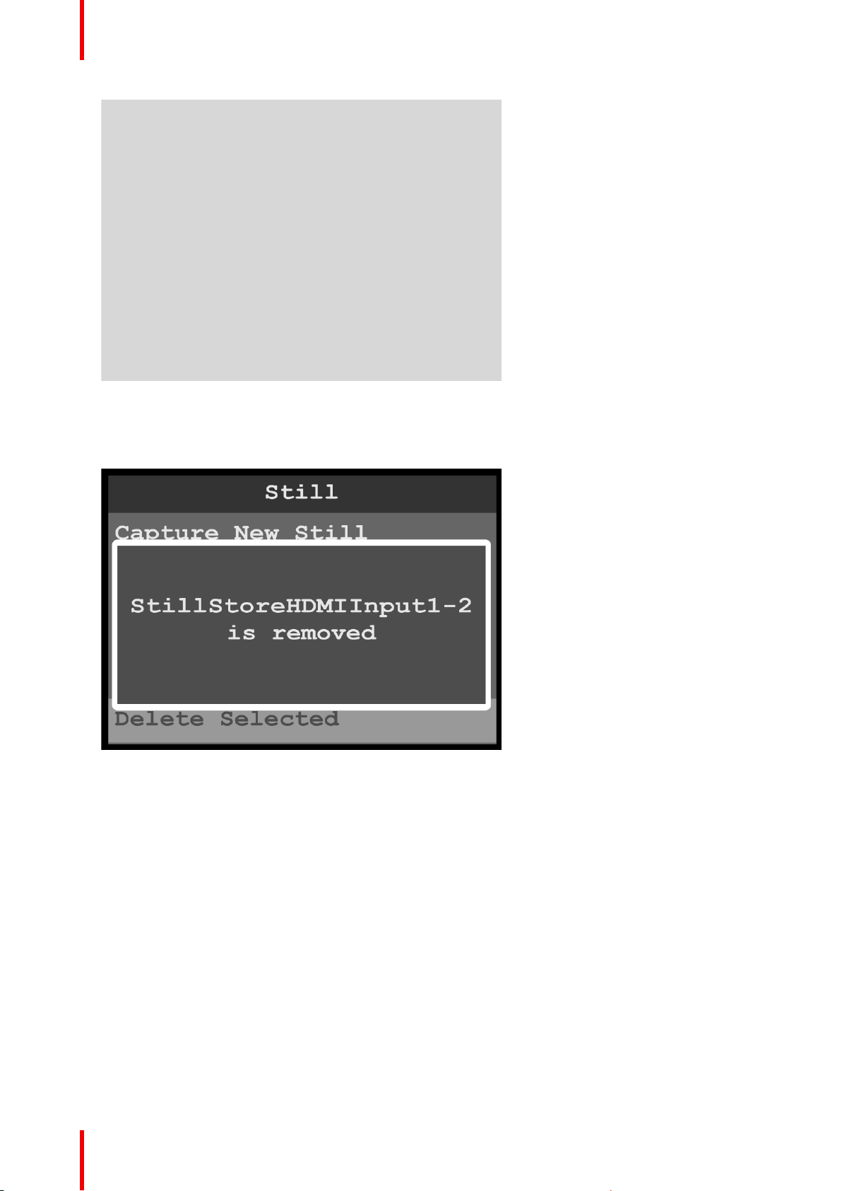
Delete Selected
1. Select the still to be deleted.
2. Select Delete Selected on the Still menu.
The system displays a message that asks if you really want to delete the still.
R5906167 /00 ImagePRO–4K Video Processor
55
Page 56
Menu orientation
Image 6-36: Still menu: Delete message
3. Select Yes to delete the selected still.
Select No to keep the still.
Once the still has been deleted, the system displays a message that says that the still has been removed.
Image 6-37: Still menu: Still removed
6.6 Preset menu
General
This section provides information about setting up and using presets. A preset is a register that enables you to
store destination setups and to recall them. Any configuration — different input sources, mapped output
channels, masks, etc.—can be saved as a preset and recalled.
To enter the Preset menu from the Setup menu, scroll to and select Preset.
56
R5906167 /00 ImagePRO–4K Video Processor
Page 57
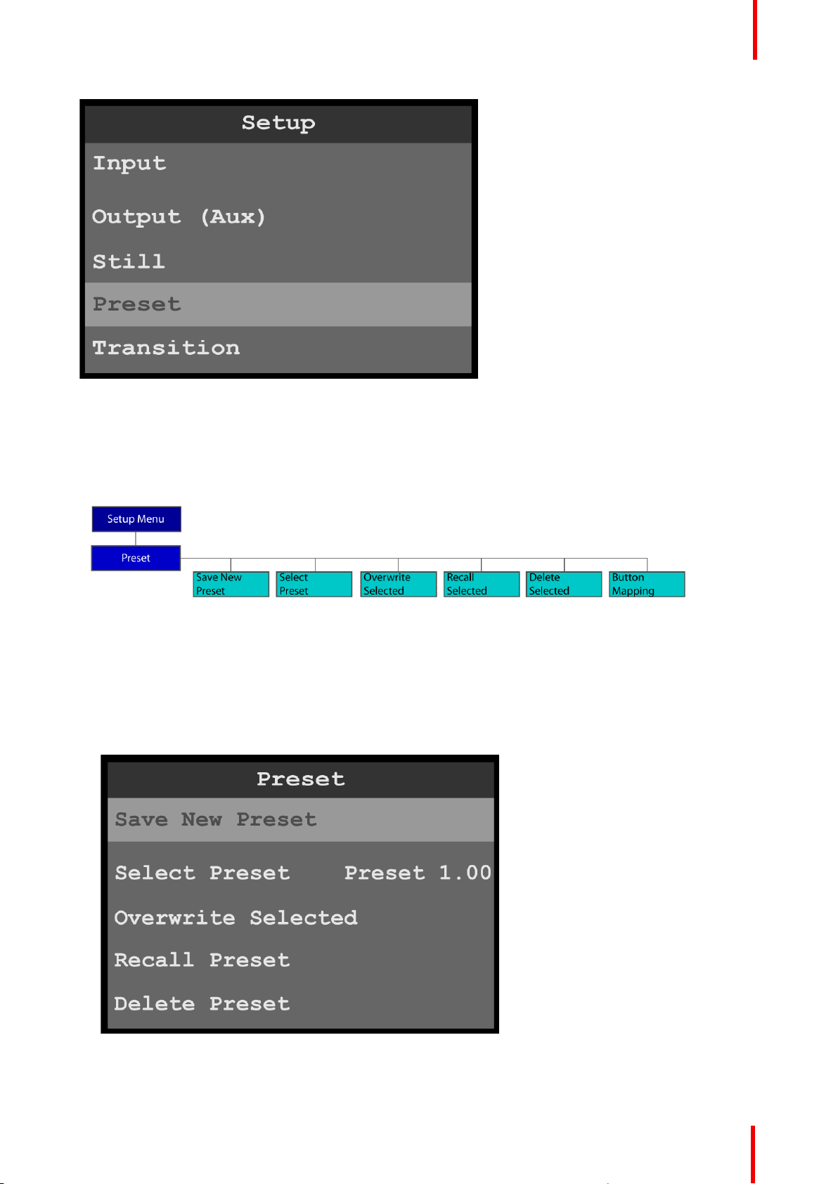
Image 6-38: Setup menu: Preset
Use the Preset menu to create, select, recall, and delete presets.
Preset menu tree
Refer to Image 6-39 for an illustration of the Preset menu tree.
Menu orientation
Image 6-39: Preset menu tree
Save New Preset
1. Select Save New Preset on the Preset menu.
Once Input is selected, the highlight bar turns from gray to cyan. Turning the adjust knob scrolls through
the available inputs.
2. Scroll to and select the input to be configured.
Image 6-40: Preset: Save New Preset
R5906167 /00 ImagePRO–4K Video Processor
57
Page 58
Menu orientation
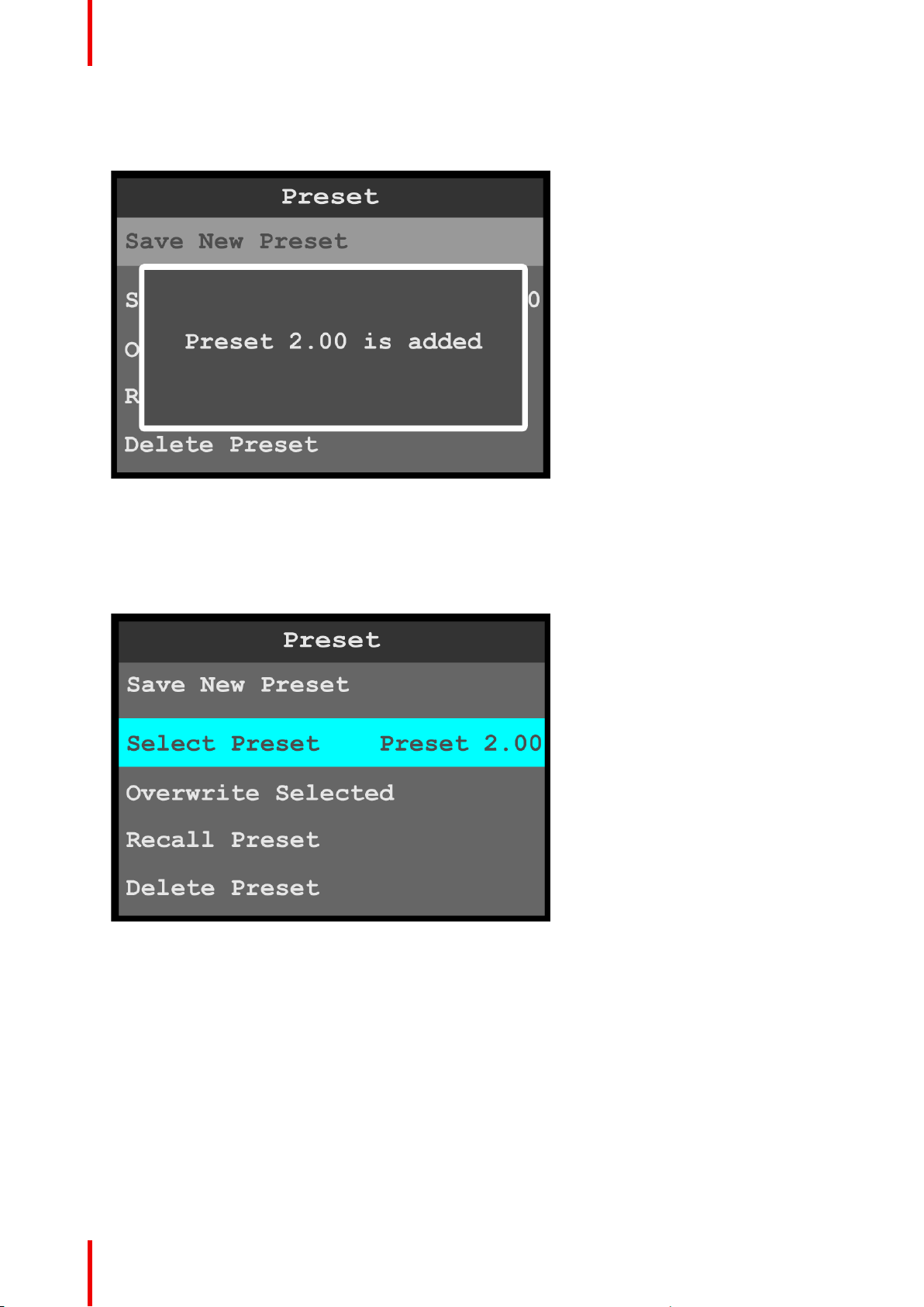
Once Save New Preset is selected, the system saves the current configuration as a preset and assigns it a
number. Once the preset is saved, the system displays a message that says that the preset has been
added.
Image 6-41: Preset saved message
Select Preset
1. Select Select Preset on the Preset menu to select a preset.
Once Select Preset is selected, the highlight bar turns from gray to cyan. Turning the adjust knob scrolls
through the available presets.
Image 6-42: Preset: Select Preset
2. Use the adjust knob to scroll to and select the desired preset.
3. Select Recall Preset to recall the newly selected preset.
Overwrite Preset
1. Select Overwrite Preset on the Preset menu to overwrite the currently displayed preset with the currently
selected preset.
For example, if Preset 1.00 is currently displayed and Preset 2.00 is currently selected, selecting Overwrite
Preset overwrites Preset 1.00 with Preset 2.00. Preset 1.00 is not renumbered, but the properties of Preset
1.00 are overwritten with the properties of Preset 2.00, so that the two presets now have the same effect.
Recall Preset
1. Select Recall Preset to recall the currently selected preset and make it active.
58
R5906167 /00 ImagePRO–4K Video Processor
Page 59
Delete Preset
1. Select Delete Preset to delete the currently selected preset.
The system displays a message that asks if you really want to delete the preset.
Image 6-43: Preset menu: Delete message
Menu orientation
2. Select Yes to delete the selected preset.
Select No to keep the preset.
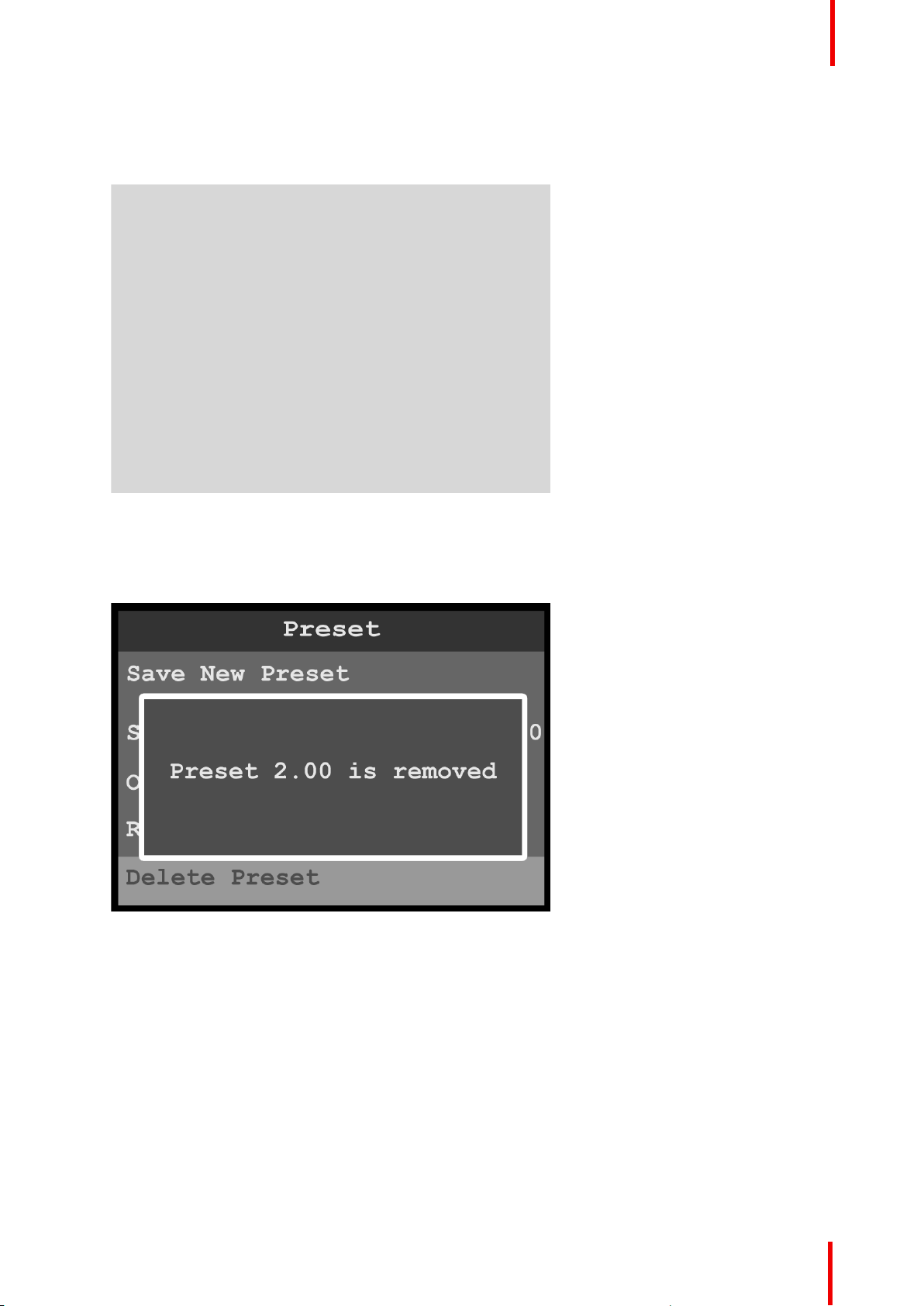
Once the preset has been deleted, the system displays a message that says that the preset has been
removed.
Image 6-44: Preset menu: Preset removed
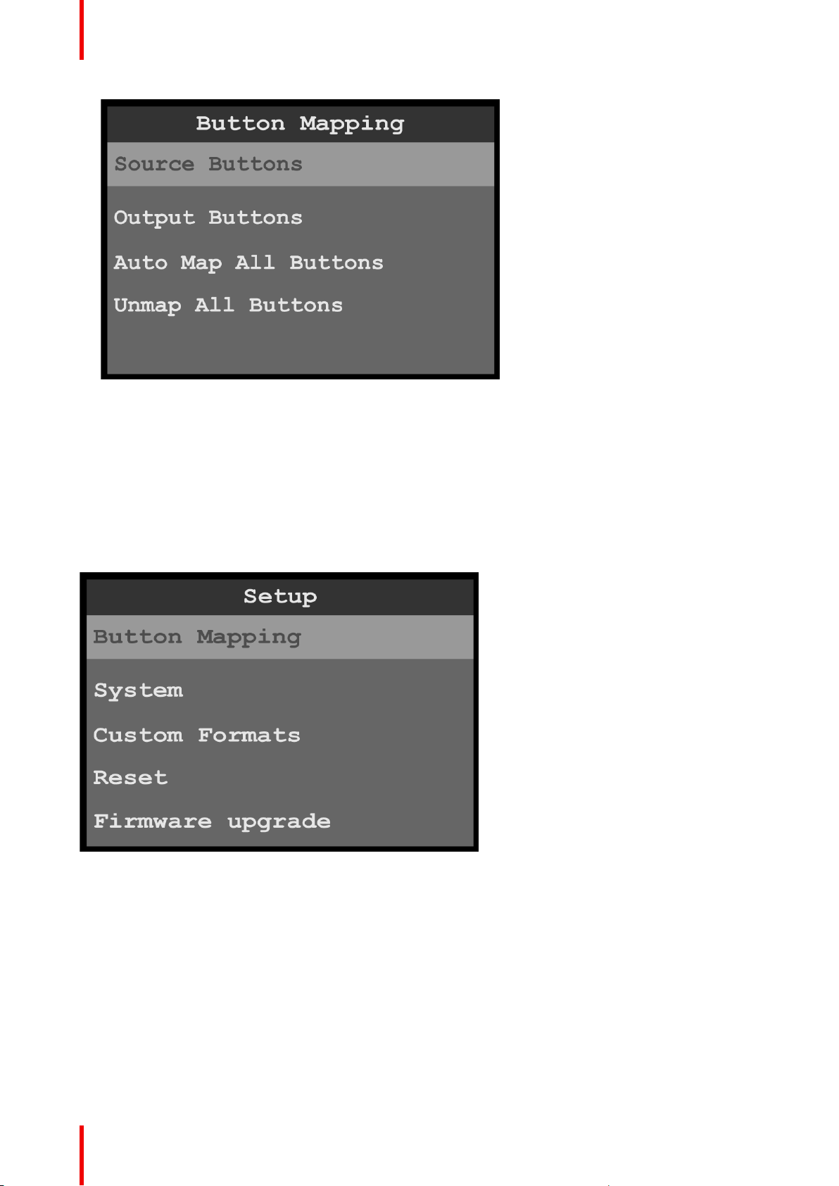
Button Mapping
1. Select Button Mapping to map and unmap source and output buttons.
R5906167 /00 ImagePRO–4K Video Processor
59
Page 60
Menu orientation
Image 6-45: Preset menu: Button Mapping
This menu is identical with the Setup / Button Mapping menu.
6.7 Button Mapping menu
General
This section provides information about mapping the front-panel buttons.
To enter the Button Mapping menu from the Setup menu, scroll to and select Button Mapping.
Image 6-46: Setup menu: Button Mapping
Use the Button Mapping menu to map the front-panel buttons to sources (input, still, and logo) and outputs.
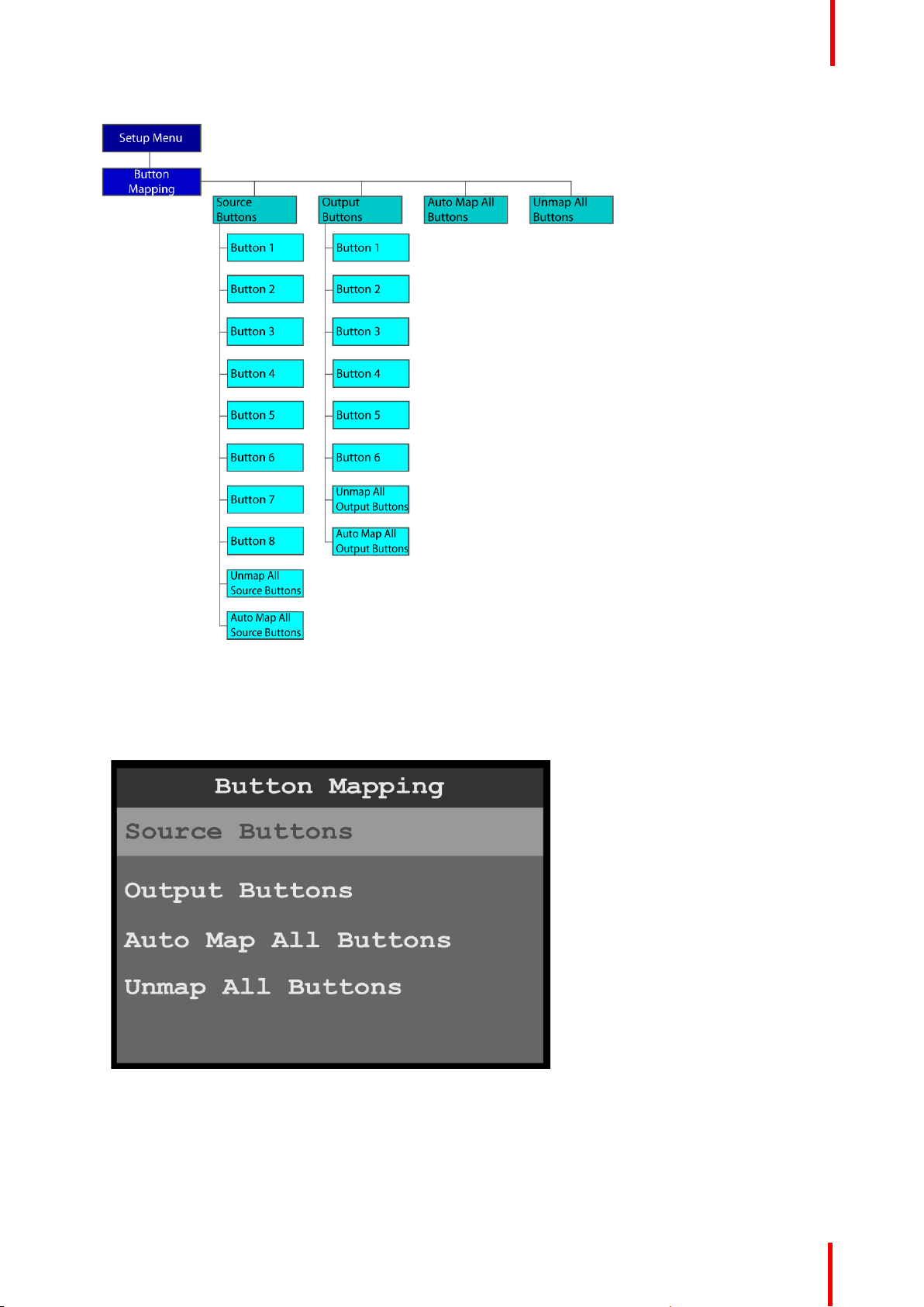
Button Mapping menu tree
Refer to Image 6-47 for an illustration of the Button Mapping menu tree.
60
R5906167 /00 ImagePRO–4K Video Processor
Page 61
Menu orientation
Image 6-47: Button Mapping menu tree
Source Buttons
1. Select Source Buttons on the Button Mapping menu.
Image 6-48: Button Mapping menu: Source Buttons
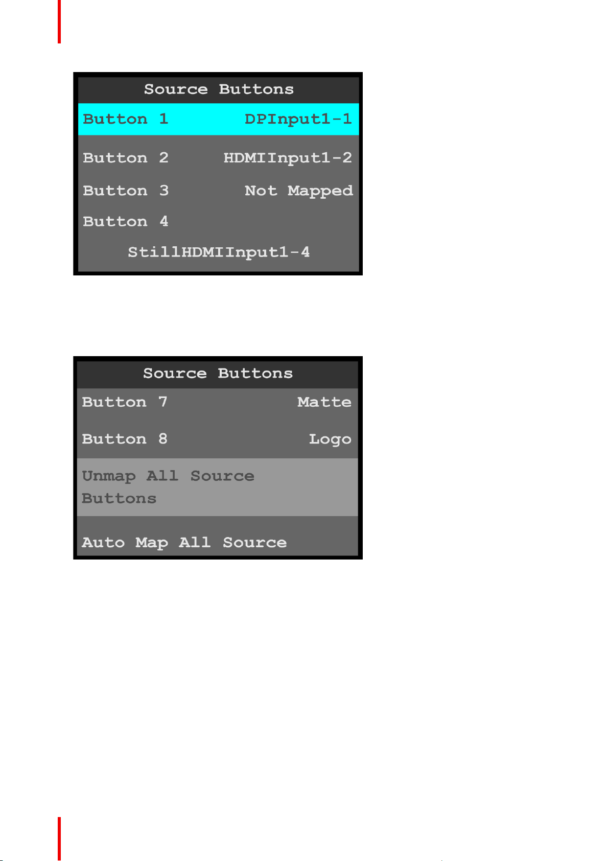
2. Scroll to and select the input to be configured.
Once the input to be configured is selected, the highlight bar turns from gray to cyan. Turning the adjust
knob scrolls through the sources available to that button.
R5906167 /00 ImagePRO–4K Video Processor
61
Page 62
Menu orientation
Image 6-49: Source Buttons menu
3. Scroll to and select the source that is to be mapped to the selected button.
4. Repeat steps 2 and 3 for each button that is to be mapped.
The default mapping for Button 7 is “Matte,” and the default mapping for Button 8 is “Logo.”
5. To unmap all of the source buttons, scroll to and select Unmap All Source Buttons.
Image 6-50: Unmap All Source Buttons
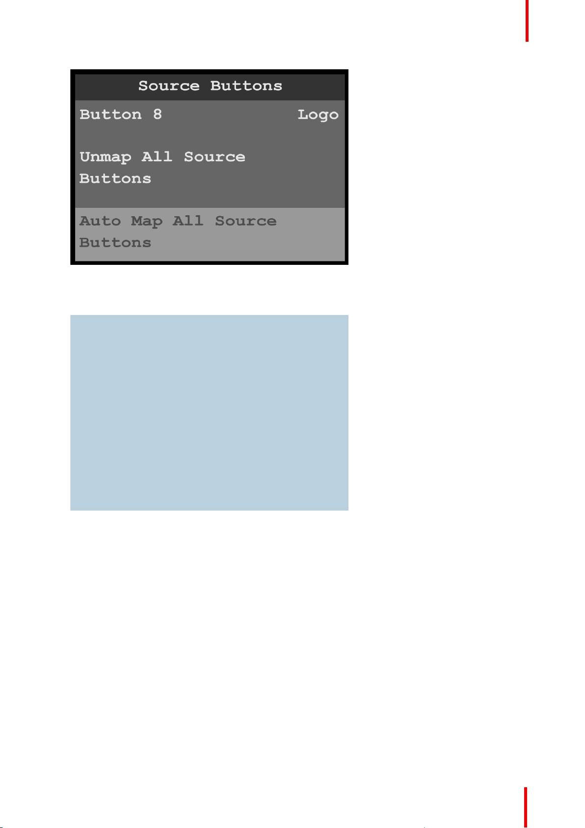
6. To automatically map all of the source buttons, scroll to and select Auto Map All Source Buttons.
62
R5906167 /00 ImagePRO–4K Video Processor
Page 63
Menu orientation
Image 6-51: Auto Map All Source Buttons
The system unmaps all currently mapped source buttons and automatically remaps them. When the
remapping is finished, the system displays a message.
Image 6-52: All source buttons mapped message
7. Select Yes to complete the auto-mapping of the source buttons.
Output Buttons
1. Select Output Buttons on the Button Mapping menu.
R5906167 /00 ImagePRO–4K Video Processor
63
Page 64
Menu orientation
Image 6-53: Button Mapping menu: Output Buttons
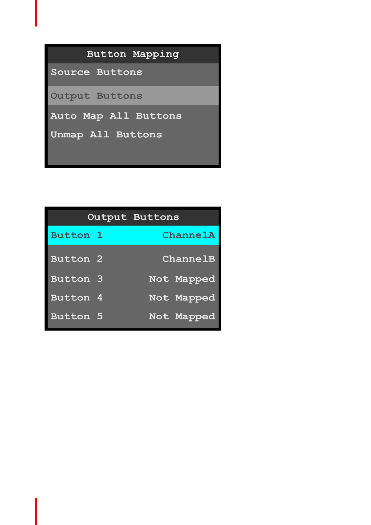
2. Scroll to and select the output button to be configured.
Once the output to be configured is selected, the highlight bar turns from gray to cyan. Turning the adjust
knob scrolls through the channels available to that button.
Image 6-54: Output Buttons menu
3. Scroll to and select the channel (A or B) to be configured.
You may also select the option “Not Mapped.”
4. Repeat steps 2 and 3 for each button that is to be mapped.
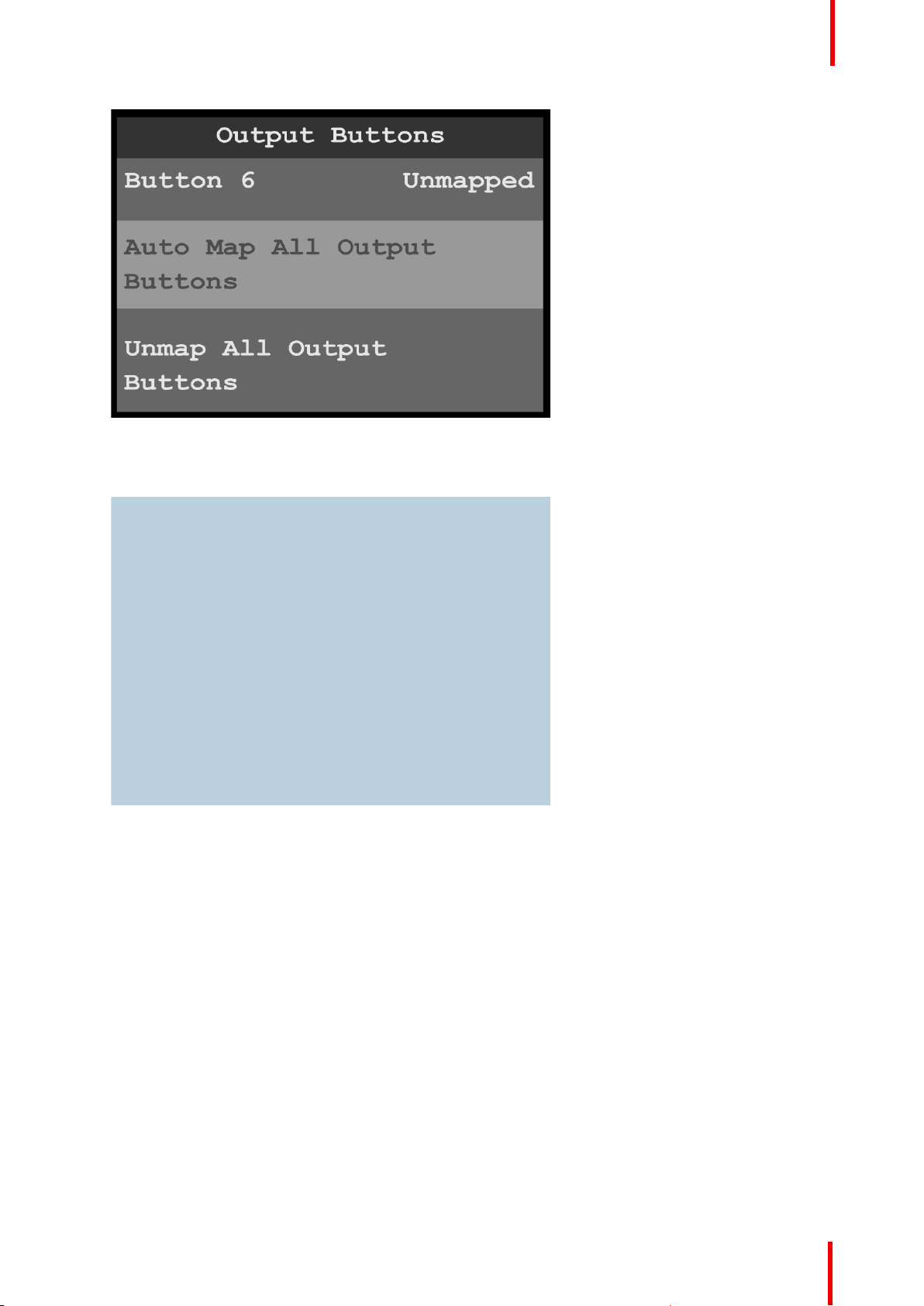
5. To automatically map all of the output buttons, scroll to and select Auto Map All Output Buttons.
64
R5906167 /00 ImagePRO–4K Video Processor
Page 65
Menu orientation
Image 6-55: Auto Map All Output Buttons
The system unmaps all currently mapped output buttons and automatically remaps them. When the
remapping is finished, the system displays a message.
Image 6-56: All output buttons mapped message
6. Select Yes to complete the auto-mapping of the output buttons.
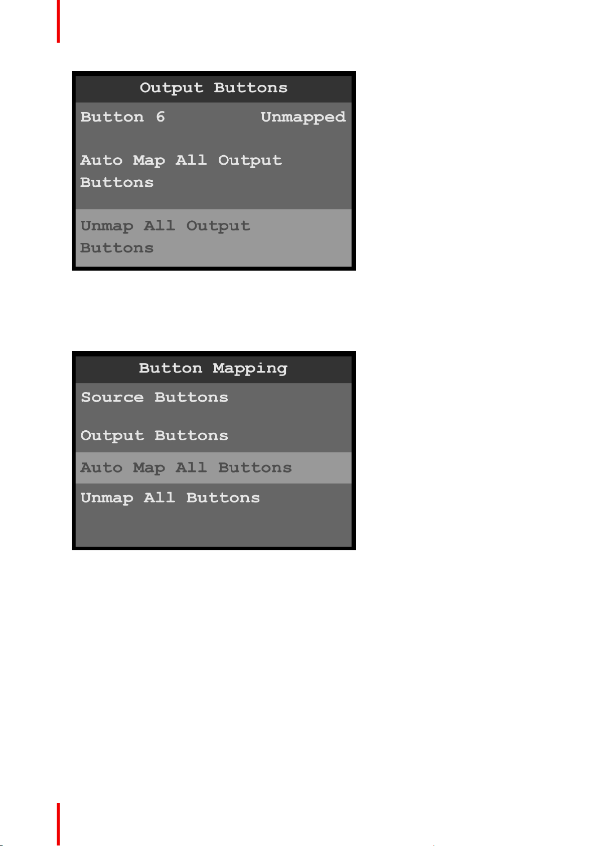
7. To unmap all of the output buttons, scroll to and select Unmap All Output Buttons.
R5906167 /00 ImagePRO–4K Video Processor
65
Page 66
Menu orientation
Image 6-57: Unmap All Output Buttons
Auto Map All Buttons
To allow the system to automatically map the front-panel buttons to all available sources and outputs…
1. Select Auto Map All Buttons on the Button Mapping menu.
66
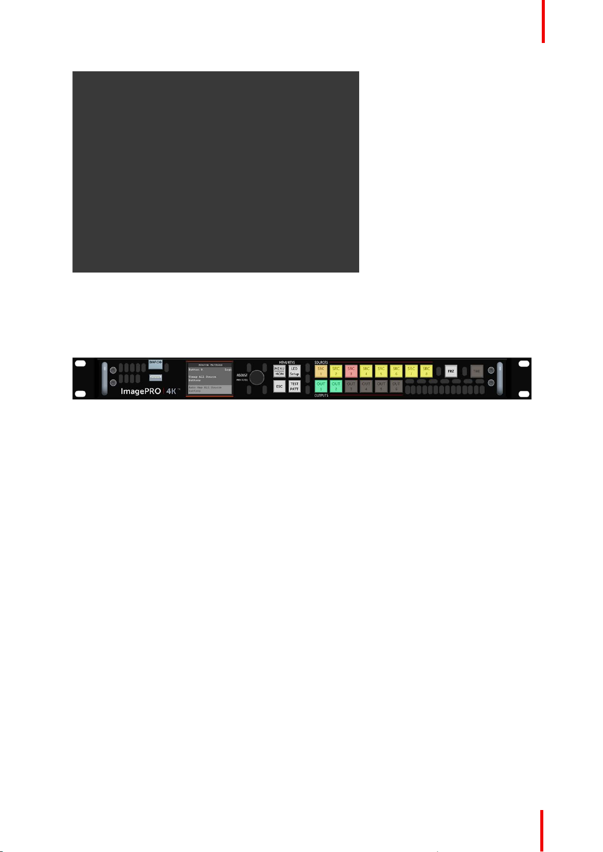
Image 6-58: Auto Map All Buttons
The system unmaps all currently mapped source and output buttons and automatically remaps them.
When the remapping is finished, the system displays the message “All buttons mapped.”
R5906167 /00 ImagePRO–4K Video Processor
Page 67
Menu orientation
Image 6-59: All buttons mapped message
2. Select Yes to complete the auto-mapping of all source and output buttons.
The default mapping for SRC 1 through 6 is input 1 through 6 on the TCI card. The default mapping for
SRC 7 is “Matte,” and the default mapping for SRC 8 is “Logo.” The default mapping for OUT 1 through 6 is
output 1 through 6 on the TCO card.
Once the system maps all of the source and output buttons, the buttons on the front panel are lit.
Image 6-60: Front-panel source and output buttons auto-mapped
Button states
Color and brightness indicate the state of the front-panel source and output buttons.
Source-button states
• Brightly lit—Button is selected.
- Green: Signal is active and assigned to PVW.
- Yellow: Input source, still, logo, or matte color is present.
- Amber: Source is active on the PGM outputs.
- Red: Loss of sync (LOS).
- Blue: Source is frozen.
- Cyan: A cue is mapped to the button. (Cues will be supported in a future software release.)
- Magenta: A user key is mapped to the button. (User keys will be supported in a future software
release.)
- White: A preset is mapped to the button.
• Dimly lit—Source is mapped but not active.
• Not lit—Button is not mapped.
Output-button states
• Lit—Button is mapped, selected, or frozen.
- Green: Button is mapped to an Aux.
- Amber: Aux is selected to view in the front-panel monitor.
- Blue: Aux is frozen.
• Dimly lit—Source is mapped but not active.
• Not lit—Button is not mapped.
R5906167 /00 ImagePRO–4K Video Processor
67
Page 68
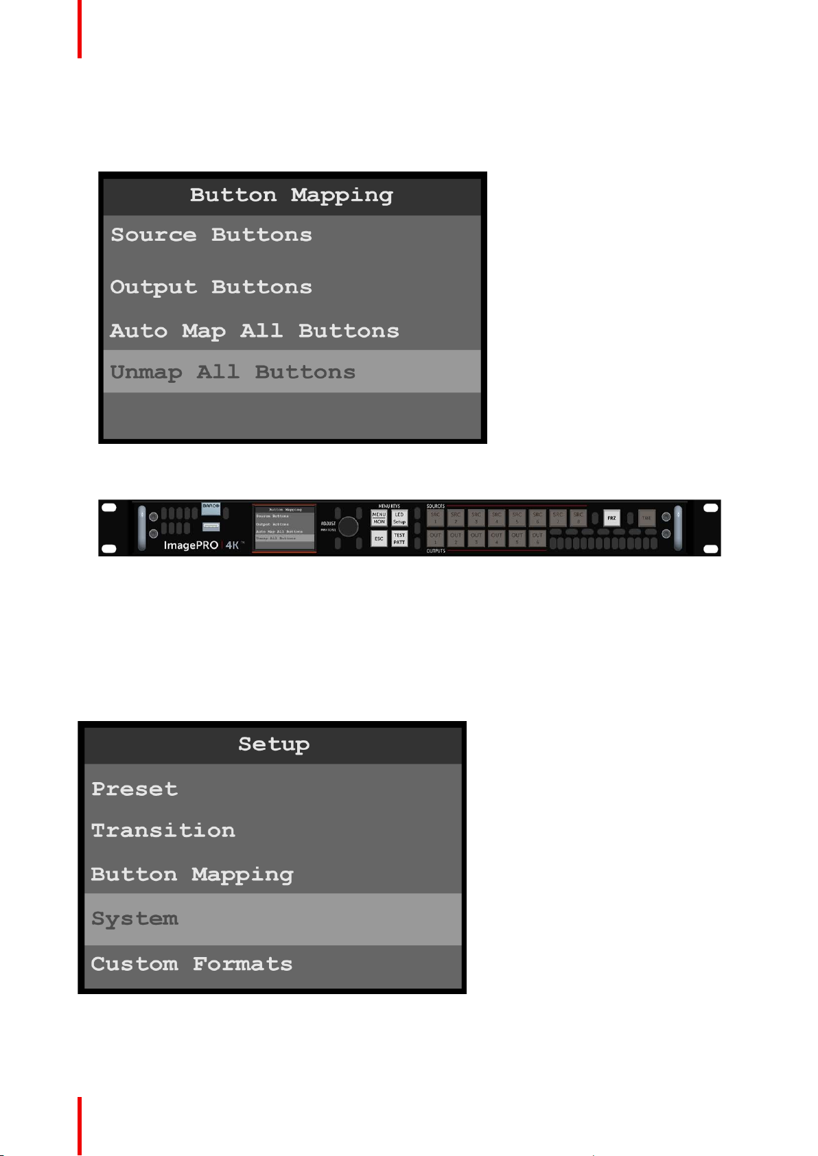
Menu orientation
Unmap All Buttons
To unmap all source and output buttons…
1. Select Unmap All Buttons on the Button Mapping menu.
Image 6-61: Unmap All Buttons
Once the system unmaps the source and output buttons, the buttons on the front panel are unlit.
Image 6-62: Front-panel source and output buttons unmapped
6.8 System menu
General
This section provides information about the System menu.
To enter the System menu from the Setup menu, scroll to and select System.
Image 6-63: Setup menu: System
Use the System menu to control system settings, such as Unit Mode, Native Rate, Genlock, Ethernet, Display
and Button Brightness and to access the System Diagnostics.
68
R5906167 /00 ImagePRO–4K Video Processor
Page 69
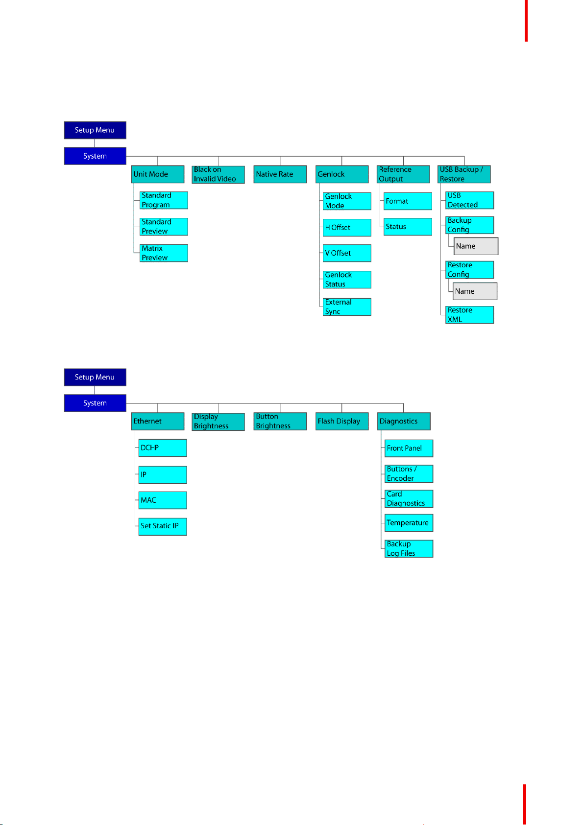
System menu tree
Refer to Image 6-64 and to Image 6-65 for an illustration of the System menu tree.
Menu orientation
Image 6-64: System menu tree
Image 6-65: System menu tree (Continued)
Unit Mode
The ImagePRO–4K video processor can operate in one of three unit modes.
• In Standard Program mode, when the operator selects a source from the front panel that source is
automatically transitioned to both Aux outputs.
• In Standard Preview mode the operator can preview the input on the Display screen, before taking it to
program by pressing the Take button.
Note that to preview the selected input on the display screen, the MENU/MON menu key must be set to
monitor mode.
• In Matrix Preview mode the ImagePRO–4K video processor acts as if it were a scaling matrix switcher.
Matrix Preview mode may be selected from the front panel of the unit, but it must be used through the
EMTS GUI.
Standard Program and Standard Preview modes allow for a single input to route to up two Aux channels out.
Because only one source is routed to both Aux channels at the same time, all six inputs can have a 4K60p
R5906167 /00 ImagePRO–4K Video Processor
69
Page 70
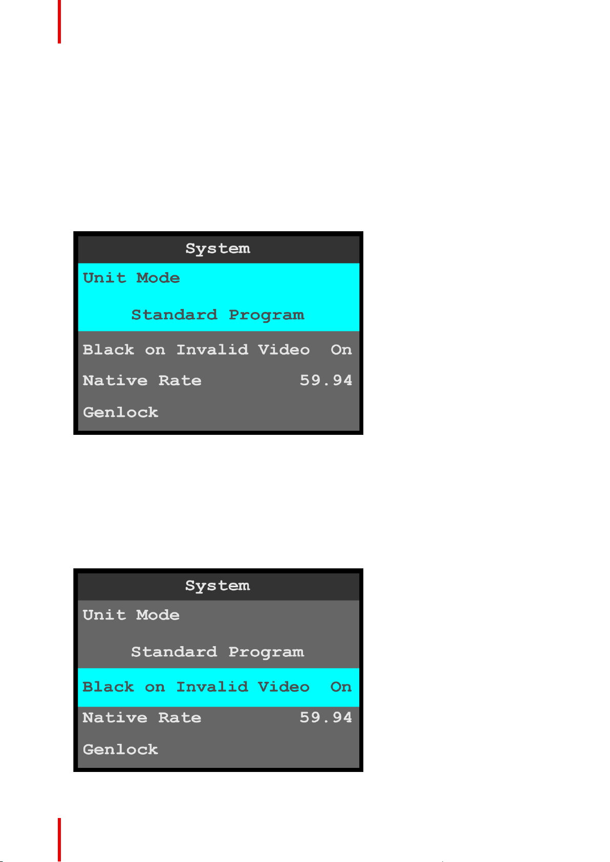
Menu orientation
source connected. The system dynamically allocates input connector capacity as each source is actively
switched. Each output connected to a display must be assigned to one of the two Aux channels. Even though
all six output connectors can possibly show a picture, the output rate and "area of interest" are defined in the
Aux channel(s).
Matrix Preview mode is capable of providing a single input to multiple outputs, as well as multiple inputs to
multiple outputs. Because this mode is capable of routing more than one input to the outputs, the signal
bandwidth capacities for each connector must be defined by the user. Each output can have a different signal
rate from the others, as well as a unique "area of interest."
To select the unit mode…
1. Select Unit Mode on the System menu.
Once Unit Mode is selected, the highlight bar turns from gray to cyan. Turning the adjust knob scrolls
through the available unit modes.
Image 6-66: System menu: Unit Mode
2. Scroll through and select the desired unit mode: Standard Program, Standard Preview, or Matrix
Preview.
Black on Invalid Video
Black on Invalid Video outputs a black screen if system cannot process the input source (for example if there
is a loss of sync). The default setting is On.
1. Select Black on Invalid Video on the System menu.
Once Black on Invalid Video is selected, the highlight bar turns from gray to cyan.
70
Image 6-67: System menu: Black on Invalid Video
R5906167 /00 ImagePRO–4K Video Processor
Page 71
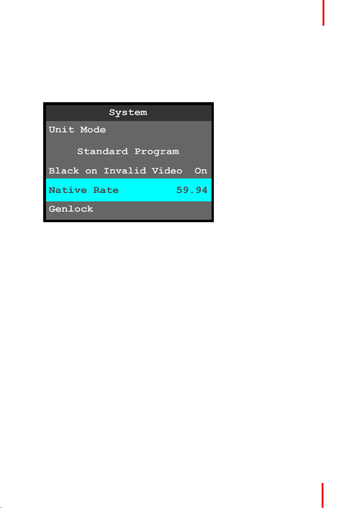
2. Use the adjust knob to scroll to and select either On or Off.
If Black on Invalid Video is set to Off, unpredictable output may result.
Native Rate
Native Rate allows the operator to adjust the native rate of the system.
1. Select Native Rate on the System menu.
Once Black on Invalid Video is selected, the highlight bar turns from gray to cyan.
Menu orientation
Image 6-68: System menu: Native Rate
2. Scroll through and select from among the native rate options.
The native rate of the system is measured in Hz (cycles per second). Available selections are:
23.98 47.95
24.00 48.00
25.00 50.00
29.97 59.94
30.00 60.00
The native rate must match the general frame rate in the event where the unit is used.
Genlock
Genlock allows the operator to adjust the Genlock parameters of the system.
1. Select Genlock on the System menu.
R5906167 /00 ImagePRO–4K Video Processor
71
Page 72
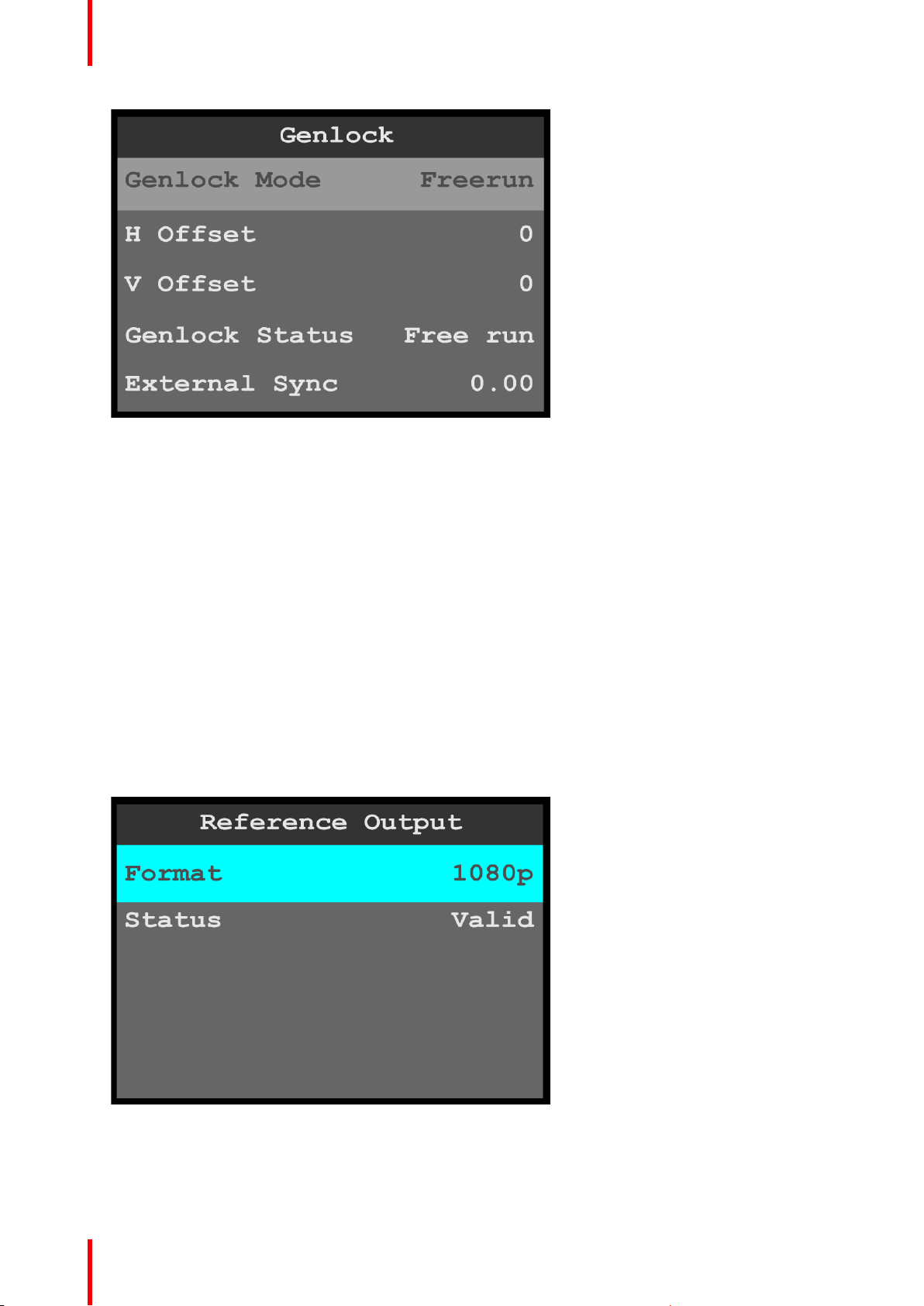
Menu orientation
Image 6-69: System menu: Genlock
• The Genlock Mode options are Freerun and Lock to External.
The default setting is Freerun.
• Use the H Offset to adjust the H Sync to match a Genlock situation.
The adjustment is in ms.
• Use the V Offset to adjust the V Sync to match a Genlock situation.
The adjustment is in ms.
• Genlock Status reports the status of the system’s Genlock Mode.
• External Sync displays the detected rate, in Hz, of the incoming reference signal, if present.
2. Scroll to and select the desired Genlock parameter.
Once a parameter is selected, the highlight bar for that parameter turns from gray to cyan.
3. Scroll through and select the options for the desired Genlock parameter.
Reference Output
Reference Output allows the operator to adjust the format of the reference output.
1. Select Reference Output on the System menu.
2. Select Format on the Reference Output menu.
Once Format is selected, the highlight bar turns from gray to cyan.
Image 6-70: Reference Output menu: Format
3. Scroll through and select the desired reference-output format.
Status displays whether the selected reference-output format is valid or invalid.
72
R5906167 /00 ImagePRO–4K Video Processor
Page 73
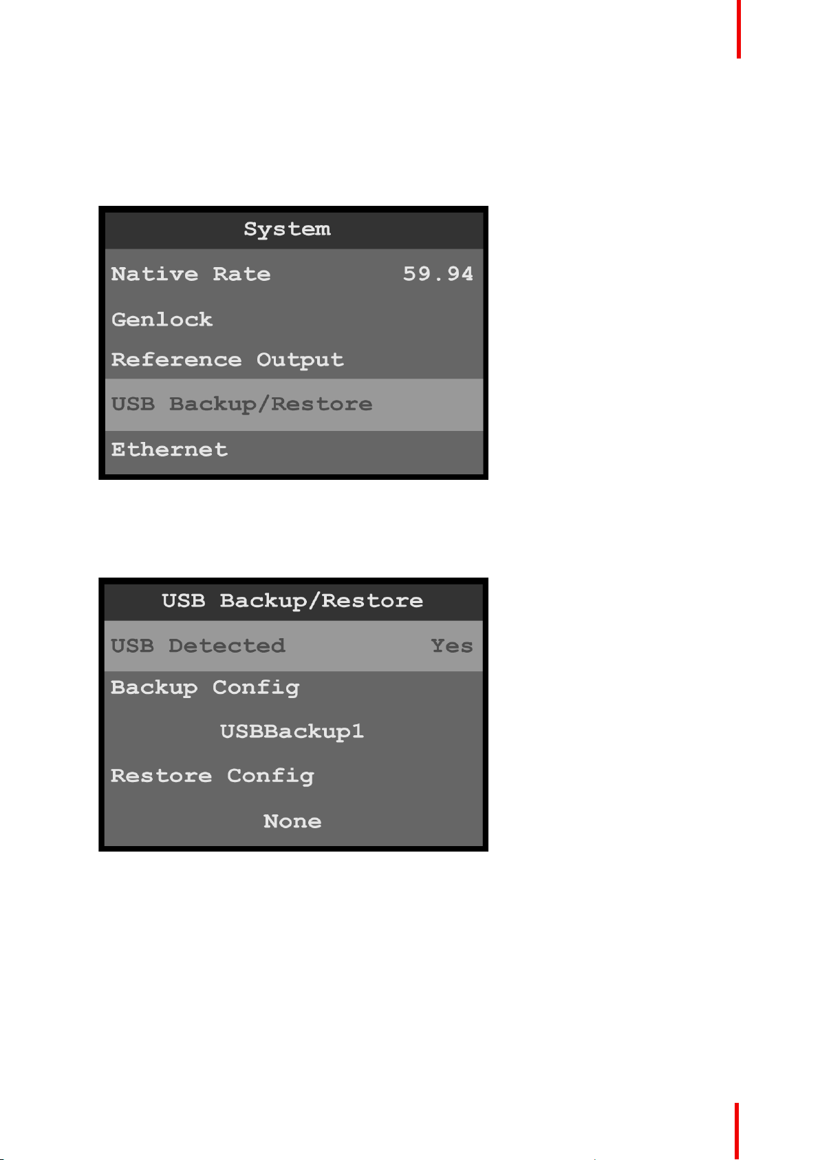
Menu orientation
USB Backup/Restore
USB Backup/Restore allows the operator to create a system backup file, and it allows the operator to use that
system backup file to restore the system.
1. Insert a FAT32-formatted USB drive in the front-panel USB port.
2. Select USB Backup/Restore on the System menu.
Image 6-71: System menu: USB Backup/Restore
The system detects if a FAT32-formatted USB drive is in the front-panel USB port. If the system detects no
USB drive in the USB port, the top line of the USB Backup/Restore menu reads, “USB Detected – No.” If
the system detects a USB drive in the USB port, the top line of the USB Backup/Restore menu reads,
“USB Detected – Yes.”
Image 6-72: USB Backup/Restore: USB Detected
To create a backup file…
1. Select Backup Config on the USB Backup/Restore menu.
Once Backup Config is selected, the highlight bar turns from gray to cyan, and the first character of the
backup config file name is highlighted in green.
R5906167 /00 ImagePRO–4K Video Processor
73
Page 74
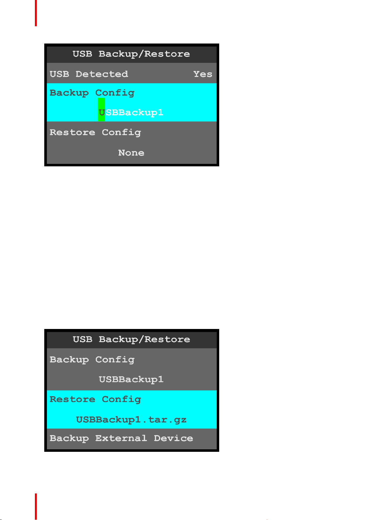
Menu orientation
Image 6-73: USB Backup/Restore: Backup Config
2. Either…
a) Press the adjust knob to accept the default backup config file name.
or…
b) Use the adjust knob to adjust the first character of the backup config file name, and press the adjust
knob when the desired character is reached.
The available characters are:
• A – Z
• a – z
• 0 – 9
• - (hyphen)
• . (period)
• / (slash)
If the USB drive has an EM folder, the system creates a backup file (for example, USBBackup1.tar.gz) and
places it in a folder named EM\backup\sys.
If the USB drive does not have an EM folder, the system creates a folder named EM\backup\sys and
places the backup file in the folder named EM\backup\sys.
To restore the system with a backup file…
1. Select Restore Config on the USB Backup/Restore menu.
Once Restore Config is selected, the highlight bar turns from gray to cyan.
Image 6-74: USB Backup/Restore: Restore Config
2. Use the adjust knob to scroll through and select the desired backup config file.
74
R5906167 /00 ImagePRO–4K Video Processor
Page 75
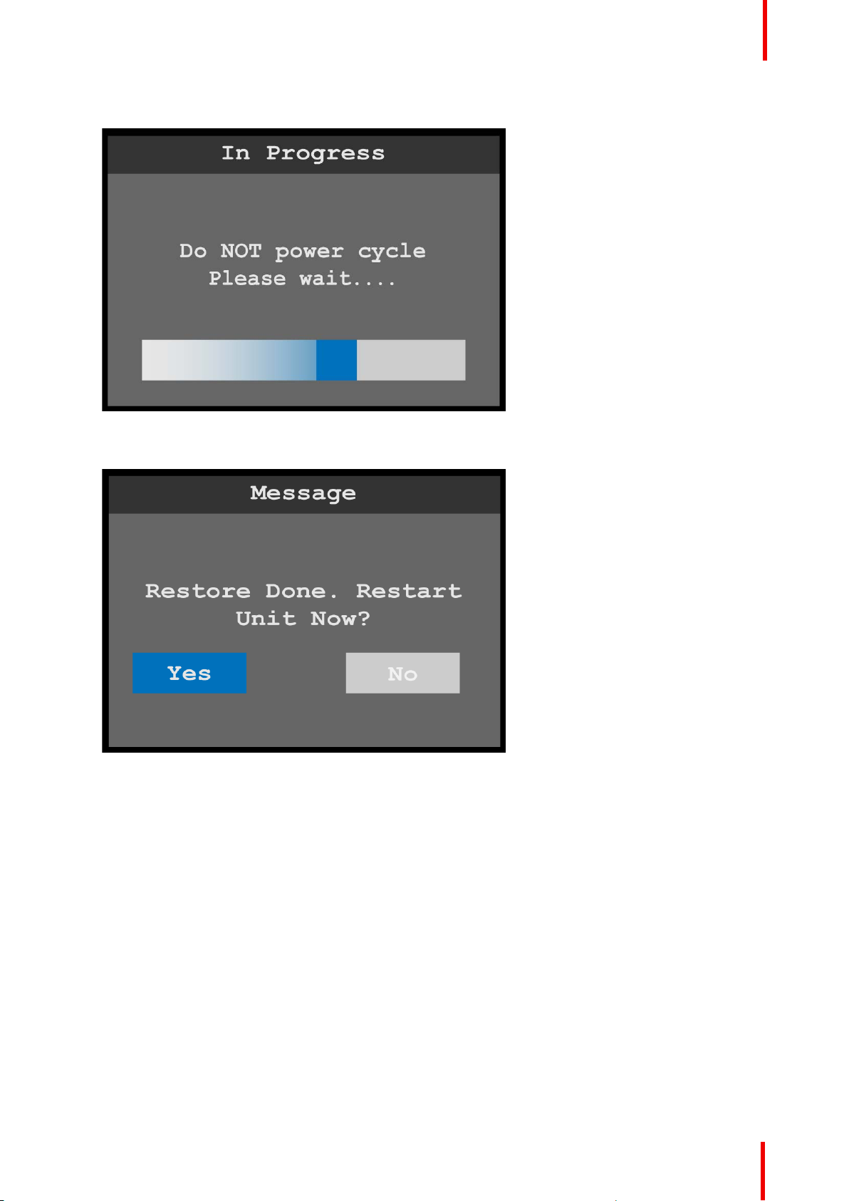
Menu orientation
The system displays a message that says that the backup is “In Progress,” and “Do NOT power cycle.”
Image 6-75: Backup In Progress message
When the restore operation is finished, the system then displays a message that asks, “Restart Unit Now?”
Image 6-76: Restore Done Restart message
3. Select Yes.
The system displays a resetting message.
R5906167 /00 ImagePRO–4K Video Processor
75
Page 76
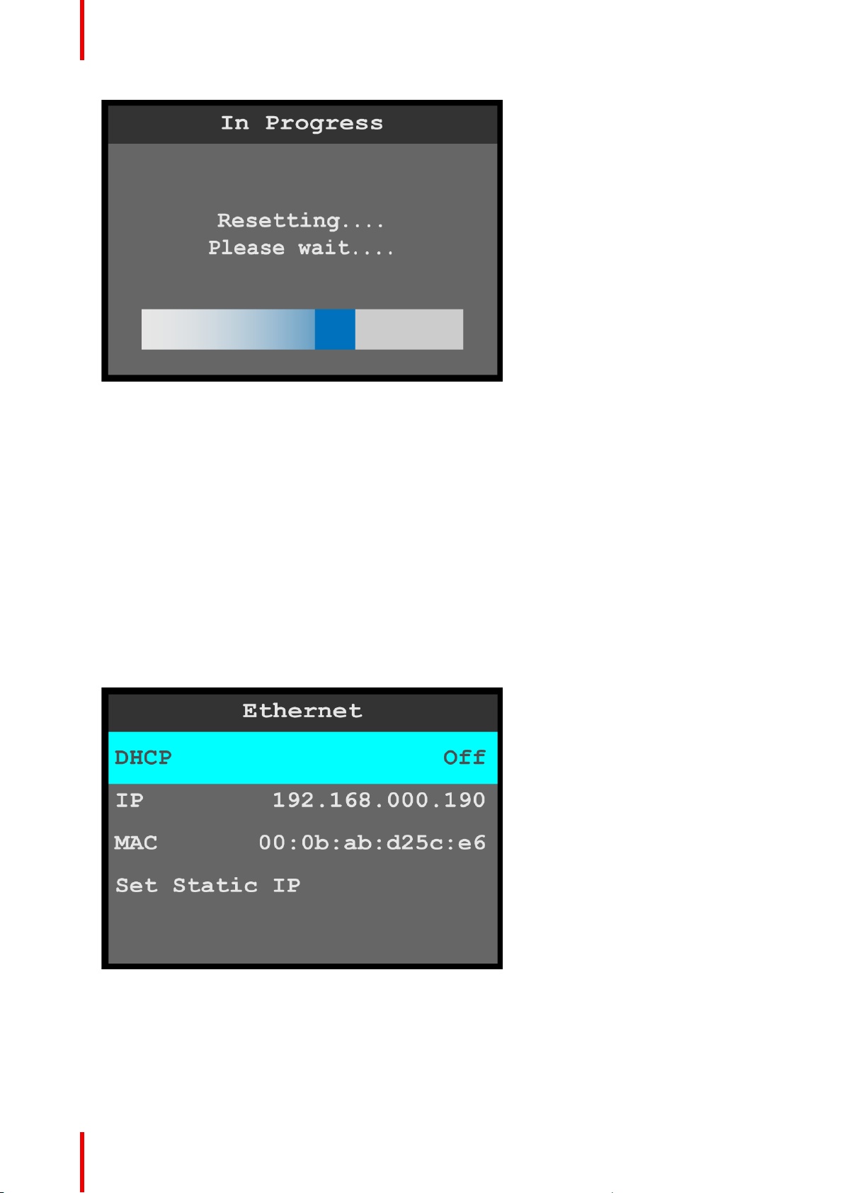
Menu orientation
Image 6-77: Resetting message
After a few minutes, the system resets, restarts, and displays the status menu.
Backup External Device and Restore External Device
Backup External Device and Restore External Device operate similarly to Backup Config and Restore Config.
Restore XML
Restore XML allows the system to upload a backup xml folder.
Ethernet
Ethernet allows the operator to adjust the Ethernet parameters of the system.
1. Select Ethernet on the System menu.
2. Scroll to and select the desired Ethernet parameter, for example DHCP (Dynamic Host Configuration
Protocol).
Once Ethernet parameter is selected, the highlight bar for that parameter turns from gray to cyan.
76
Image 6-78: Ethernet menu
• DHCP allows the operator to choose whether or not to use the Dynamic Host Configuration Protocol.
The default DHCP setting is Off.
When DHCP is set to On, a device can have a different IP address every time it connects to the
network.
• IP reports the current IP address of the system.
• MAC reports the current MAC address of the system.
R5906167 /00 ImagePRO–4K Video Processor
Page 77
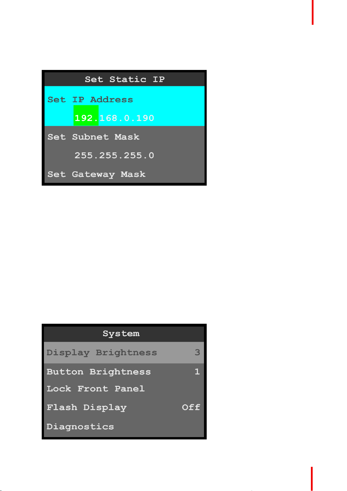
Menu orientation
• Set Static IP allows the operator to set the IP Address, Subnet Mask, and Gateway Mask.
To set a Static IP address…
1. Select Set IP Address from the Set Static IP menu.
Image 6-79: Ethernet menu: Set Static IP
Once Set IP Address is selected, the highlight bar turns from gray to cyan, and the first portion of the IP
address is highlighted in green.
2. Use the adjust knob to adjust the first portion of the IP address, and press the adjust knob when the
desired number is reached.
3. Repeat Step 2 for each portion of the IP address.
4. Select Set Subnet Mask from the Set Static IP menu.
5. Use the adjust knob to adjust the first portion of the Subnet Mask, and press the adjust knob when the
desired number is reached.
6. Repeat Step 5 for each portion of the Subnet Mask.
7. Select Set Gateway Mask from the Set Static IP menu.
8. Use the adjust knob to adjust the first portion of the Gateway Mask, and press the adjust knob when the
desired number is reached.
9. Repeat Step 8 for each portion of the Gateway Mask.
Display Brightness
1. Select Display Brightness on the System menu to adjust the brightness of the display screen.
Image 6-80: System menu: Display Brightness
R5906167 /00 ImagePRO–4K Video Processor
77
Page 78
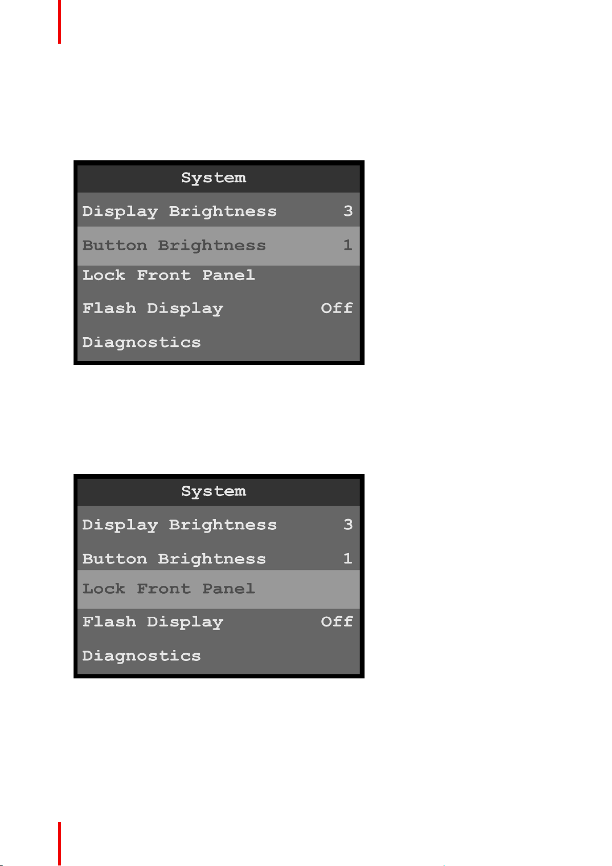
Menu orientation
Once Display Brightness is selected, the highlight bar turns from gray to cyan.
2. Scroll through the display-brightness settings, from 0 to 6, and select the desired brightness.
The default brightness setting is 3.
Button Brightness
1. Select Button Brightness on the System menu to adjust the brightness of the front-panel buttons.
Image 6-81: System menu: Button Brightness
Once Button Brightness is selected, the highlight bar turns from gray to cyan.
2. Scroll through the button-brightness settings, from 0 (off) to 6.
The default brightness setting is 1.
Lock Front Panel
1. Select Lock Front Panel on the System menu to lock the front-panel buttons.
78
Image 6-82: System menu: Lock Front Panel
Once Lock Front Panel is selected, the system displays the following message, “Front Panel Locked Press
and hold ‘Menu/Mon’ and ‘ESC’ buttons to unlock.”
R5906167 /00 ImagePRO–4K Video Processor
Page 79
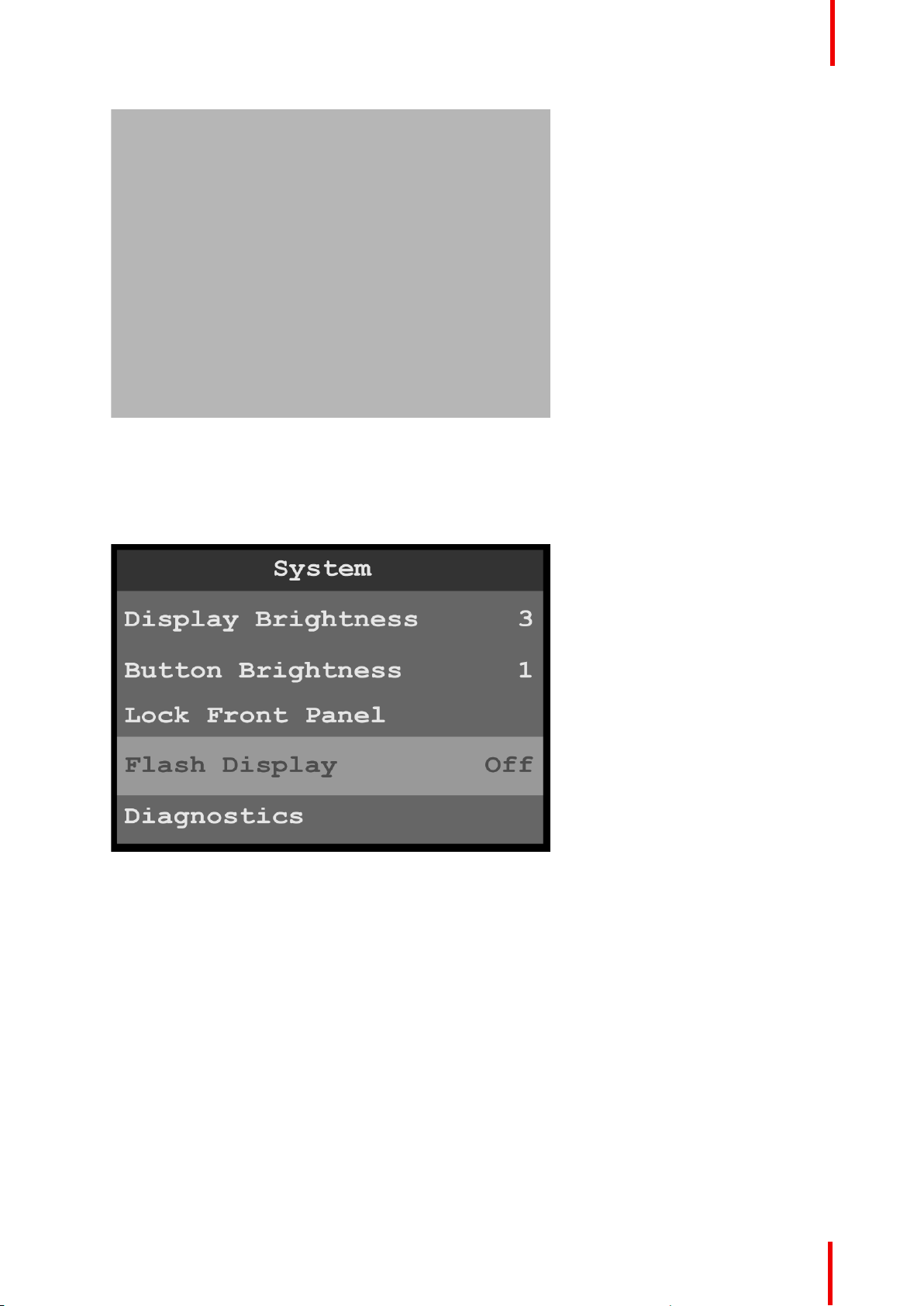
Menu orientation
Image 6-83: Lock Front Panel message
2. Press and hold the MENU/MON and ESC menu keys to unlock the front-panel buttons.
Flash Display
1. Select Flash Display on the System menu to choose between not flashing and flashing the display screen.
Image 6-84: System menu: Flash Display
Once Flash Display is selected, the highlight bar turns from gray to cyan.
2. Scroll between Off (default) and On, and select the desired setting.
When Flash Display is set to On, the display flashes from dark, to dim, to bright.
Diagnostics
The Diagnostics menu allows an operator to check if the ImagePRO– 4K unit is functioning normally. Front
panel and card operations can be checked. Various system temperatures can be monitored and backup log
files can be saved for customer service troubleshooting.
1. Select Diagnostics on the System menu to enter the Diagnostics menu.
R5906167 /00 ImagePRO–4K Video Processor
79
Page 80
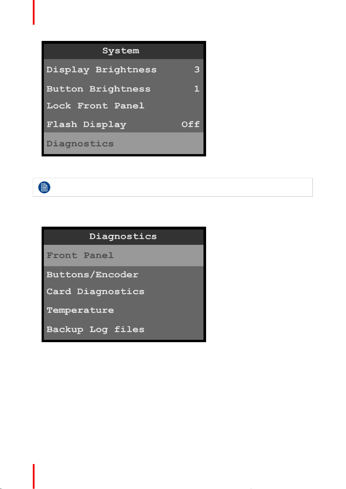
Menu orientation
Image 6-85: System menu: Diagnostics
2. Scroll to and select the diagnostic to be performed.
Do not perform diagnostics while running a show; the A/V outputs may be disrupted.
Front-panel diagnostics
1. Scroll to and select Front Panel from the Diagnostics menu.
Image 6-86: Diagnostics menu: Front Panel
When Front Panel is selected, the system displays the message “Diagnostics in progress…,” and the
display screen and the front-panel buttons flash red, then blue, then green.
When the front-panel diagnostic is finished, the system displays a message.
80
R5906167 /00 ImagePRO–4K Video Processor
Page 81

Image 6-87: Diagnostics in Progress
2. Turn the adjust knob or press any front-panel button, for example the ESC button.
Menu orientation
Image 6-88: Exit front-panel diagnostics
3. Press and hold the ESC button to return to the Diagnostics menu.
Buttons/Encoder diagnostics
1. Scroll to and select Buttons/Encoder from the Diagnostics menu.
R5906167 /00 ImagePRO–4K Video Processor
81
Page 82
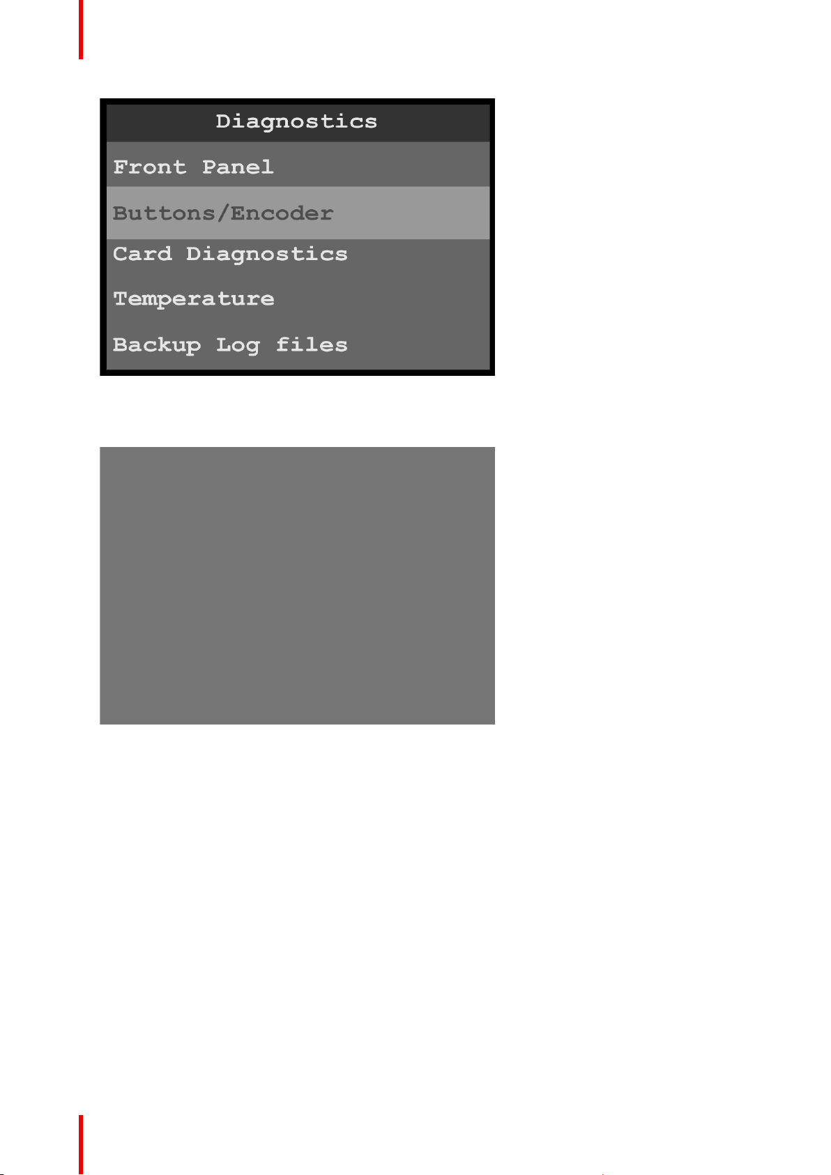
Menu orientation
Image 6-89: Diagnostics menu: Buttons/Encoder
When Buttons/Encoder is selected, the system displays the message “Diagnostics in progress…Please
press the button or turn the knob...”
Image 6-90: Diagnostics in Progress
2. Turn the adjust knob or press any front-panel button, for example the SRC 6 button.
82
R5906167 /00 ImagePRO–4K Video Processor
Page 83
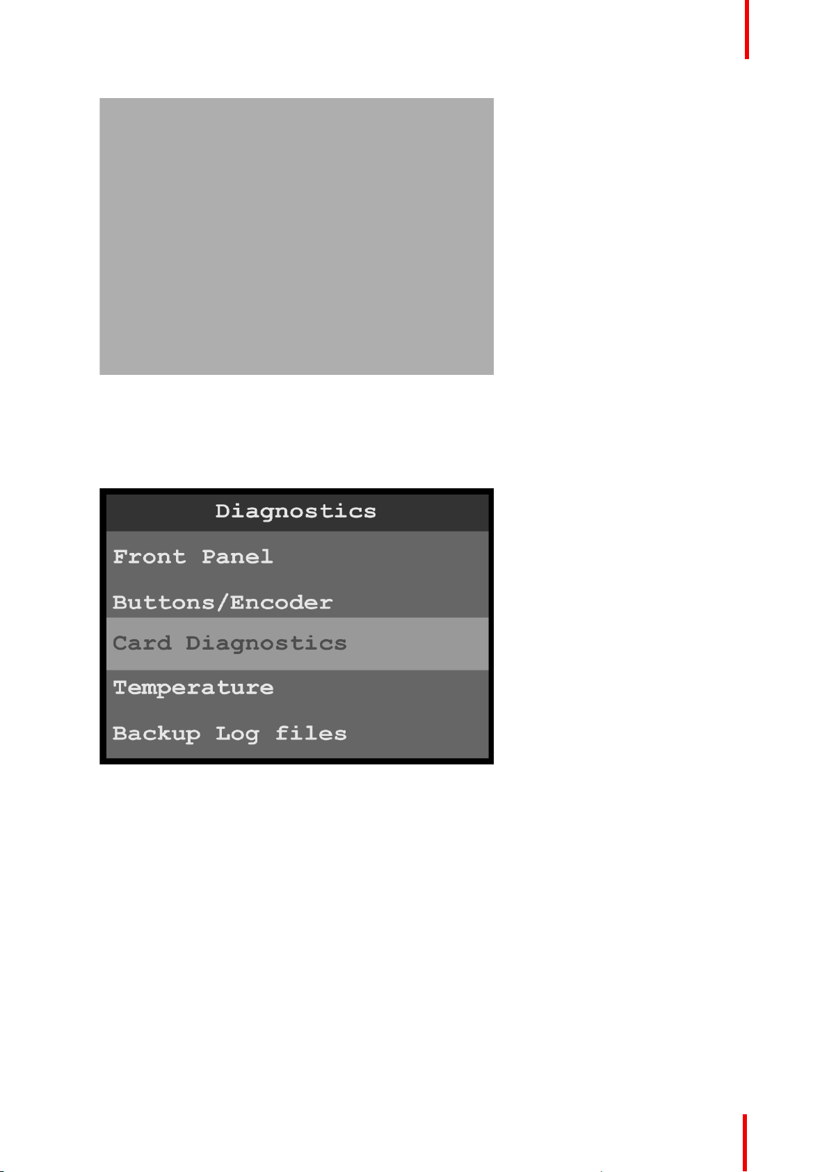
Image 6-91: Exit front-panel diagnostics
3. Press and hold the ESC button to return to the Diagnostics menu.
Card diagnostics
1. Scroll to and select Card Diagnostics from the Diagnostics menu.
Menu orientation
Image 6-92: Diagnostics menu: Card Diagnostics
2. Select Slot from the Card Diagnostics menu.
Once Slot is selected, the highlight bar turns from gray to cyan.
R5906167 /00 ImagePRO–4K Video Processor
83
Page 84
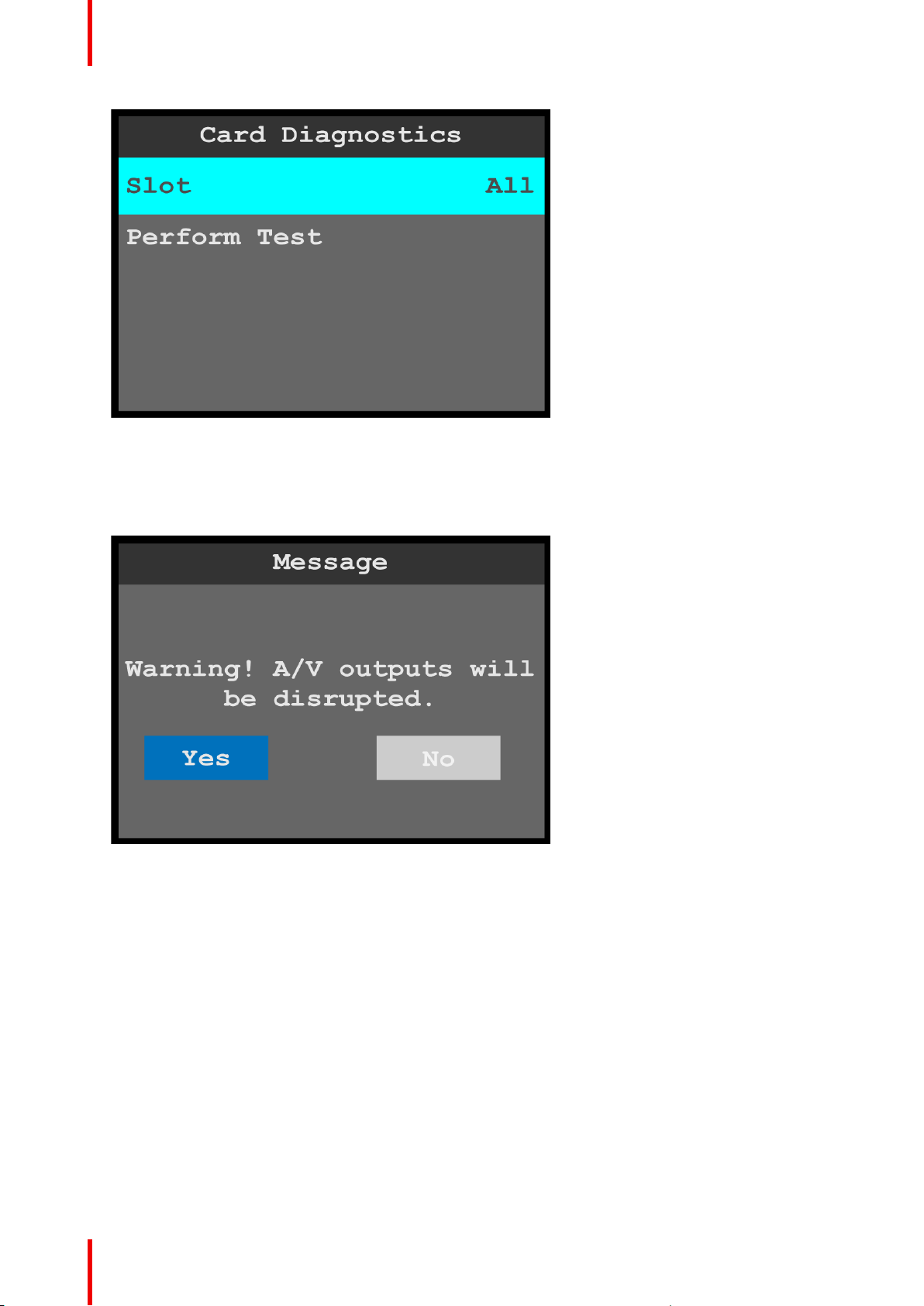
Menu orientation
Image 6-93: Card Diagnostics menu: Slot
3. Scroll through and select the desired slot.
The slot options are All, 2, and 3.
4. Scroll to and select Perform Test.
The system displays the following warning message.
Image 6-94: Card Diagnostics: Slot warning message
5. Select Yes to perform the card diagnostics.
• If No is selected, the system returns to the Card Diagnostics menu.
• If Yes is selected, the system performs the diagnostics and displays a progress screen.
84
R5906167 /00 ImagePRO–4K Video Processor
Page 85
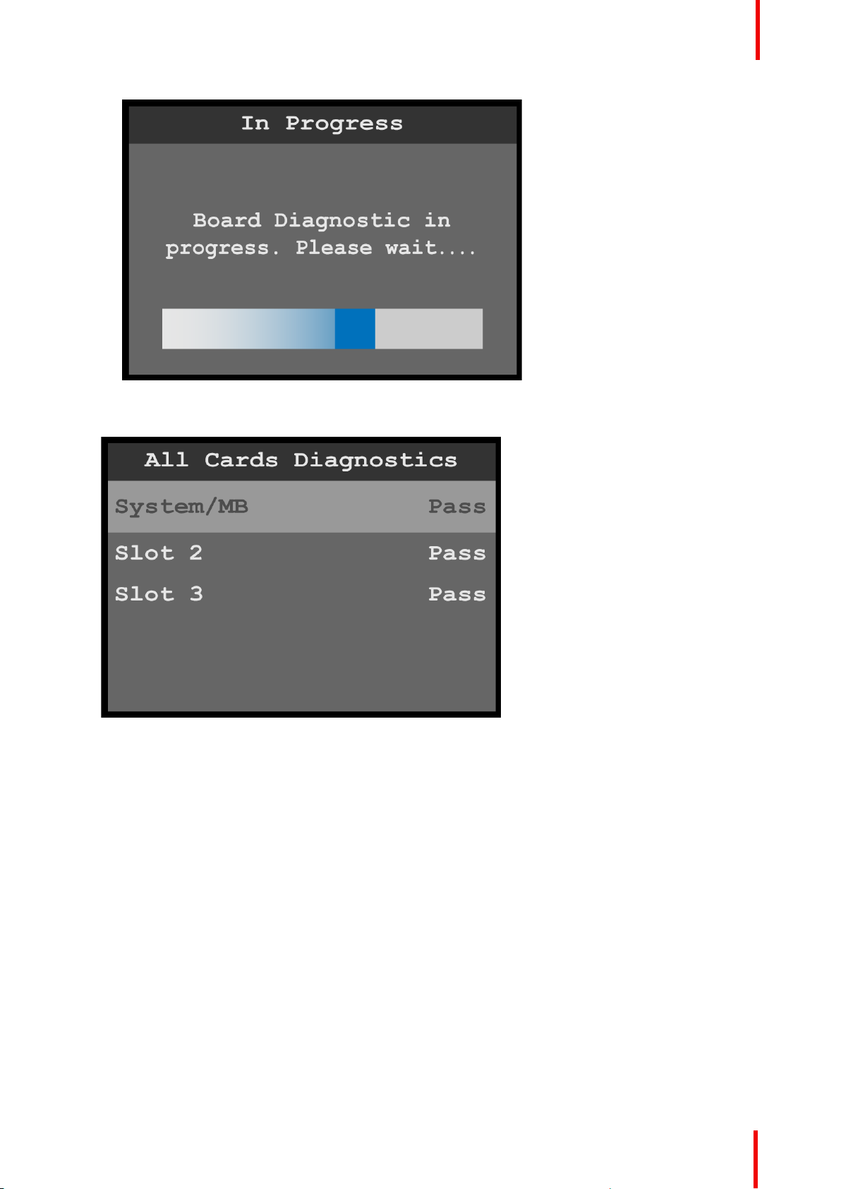
Image 6-95: Board Diagnostic in Progress message
When the diagnostic is finished, the system displays the results.
Menu orientation
Image 6-96: Board diagnostics results
6. Press the ESC key to return to the Card Diagnostics menu.
Temperature diagnostics
1. Scroll to and select Temperature from the Diagnostics menu.
The system performs the temperature diagnostics and displays the results.
R5906167 /00 ImagePRO–4K Video Processor
85
Page 86
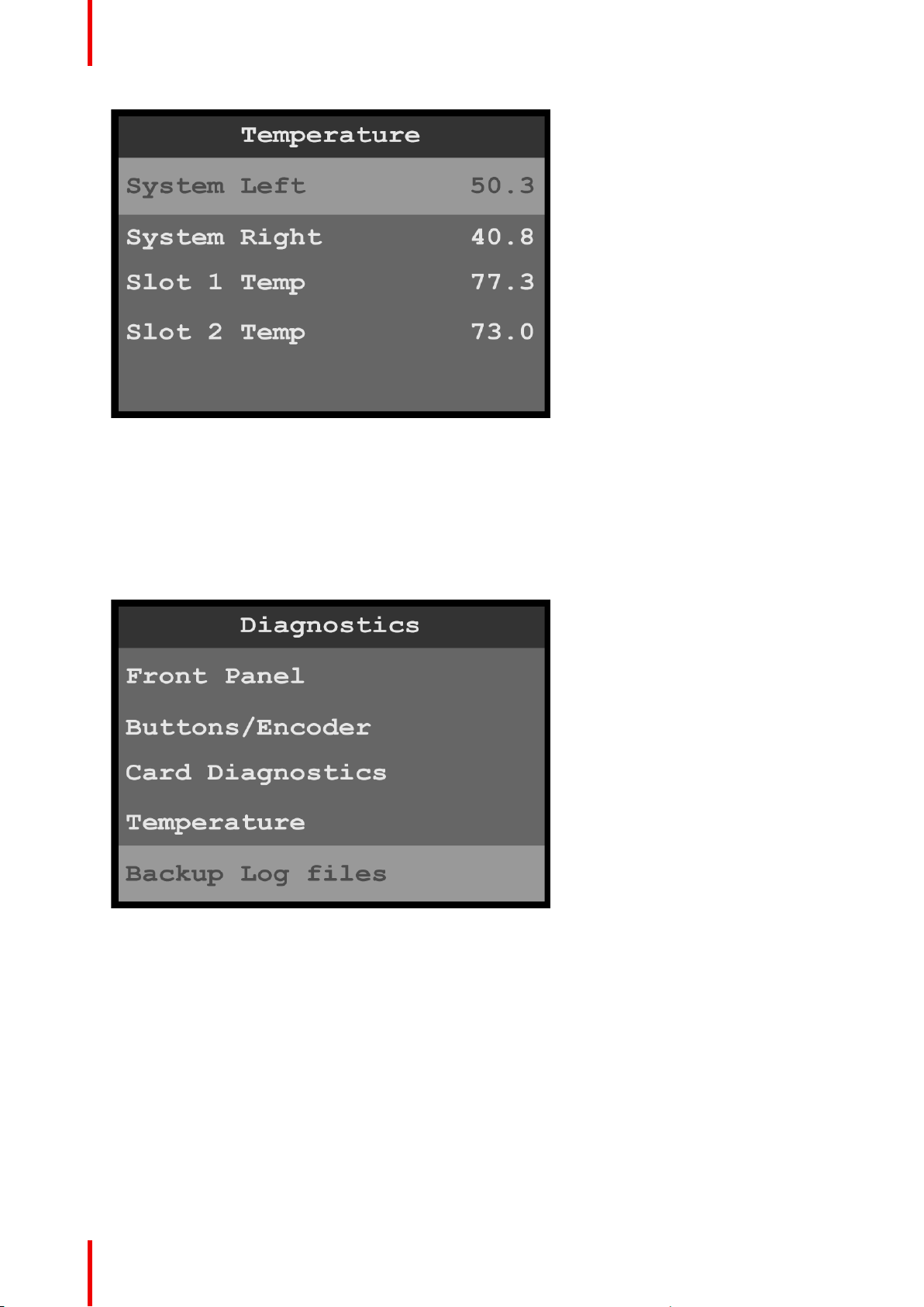
Menu orientation
Image 6-97: Temperature diagnostic results
2. Press the ESC key to return to the Diagnostics menu.
Backup Log Files
1. Insert a FAT32-formatted flash drive in the front-panel USB slot.
If there is no USB drive in the USB slot when you attempt to create backup log files, the system displays
the message “USB drive not found. Please check USB connection and retry.”
2. Scroll to and select Backup Log Files from the Diagnostics menu.
86
Image 6-98: Diagnostics menu: Backup Log Files
The system displays a progress screen.
R5906167 /00 ImagePRO–4K Video Processor
Page 87
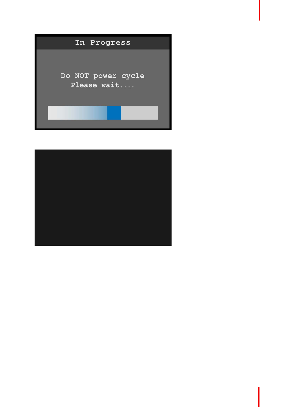
Menu orientation
Image 6-99: Backup in progress
When the backup is finished, the system displays a message that contains the name of the backup file.
Image 6-100: Backup successful message
The system stores the backup file—IP4KLogFiles.tar.gz—in the EM folder on the USB drive.
6.9 Custom Formats
General
This section provides information on creating and selecting custom formats.
To enter the Custom formats menu from the Setup menu, scroll to and select Custom formats.
R5906167 /00 ImagePRO–4K Video Processor
87
Page 88
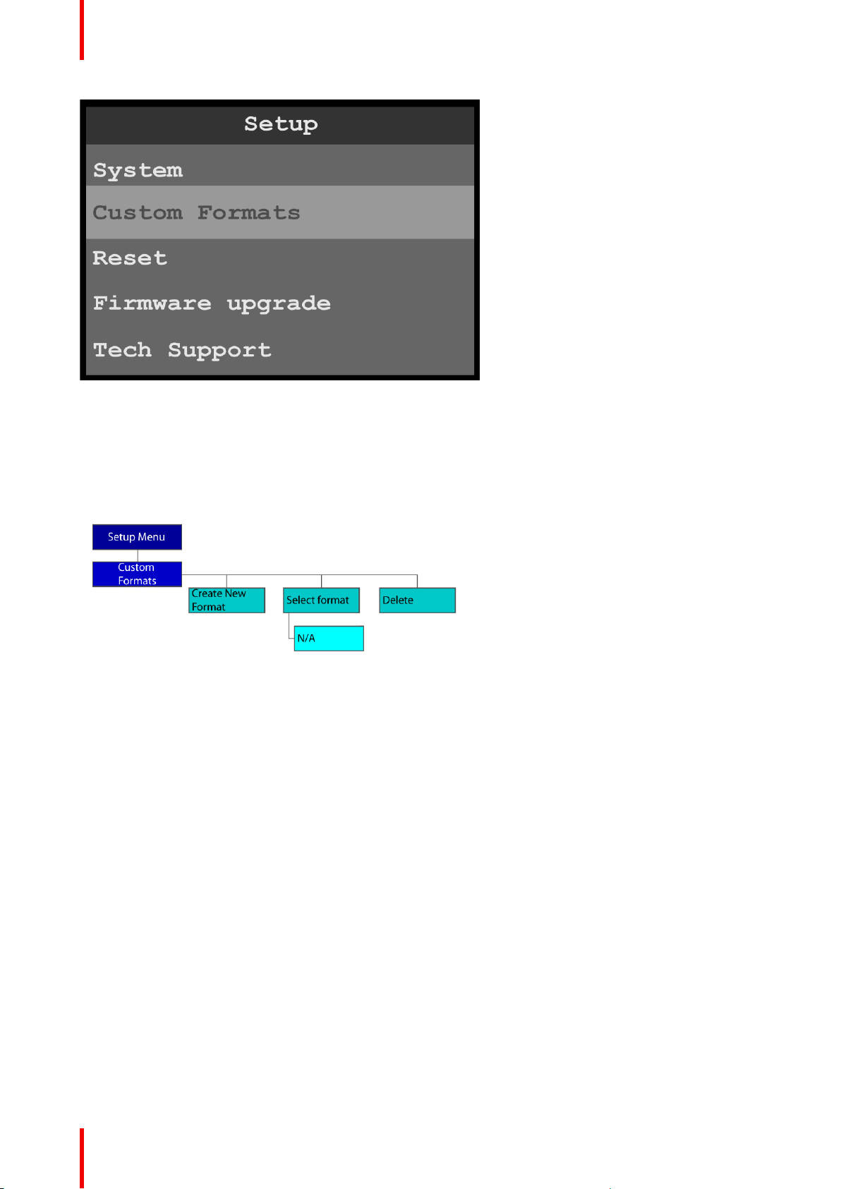
Menu orientation
Image 6-101: Setup menu: Custom Formats
Use the Custom Formats menu to create custom formats to match different output devices.
Custom Formats menu tree
Refer to Image 6–102 for an illustration of the initial Custom Formats menu tree. This reflects how the Custom
Formats menu appears on the display screen, before any custom formats are created.
Image 6-102: Custom Formats menu tree: with no custom formats
Refer to Image 6– 103 for an illustration of the Custom Formats menu tree that reflects how the Custom
Formats menu appears on the display screen, after one or more custom formats have been created.
88
R5906167 /00 ImagePRO–4K Video Processor
Page 89
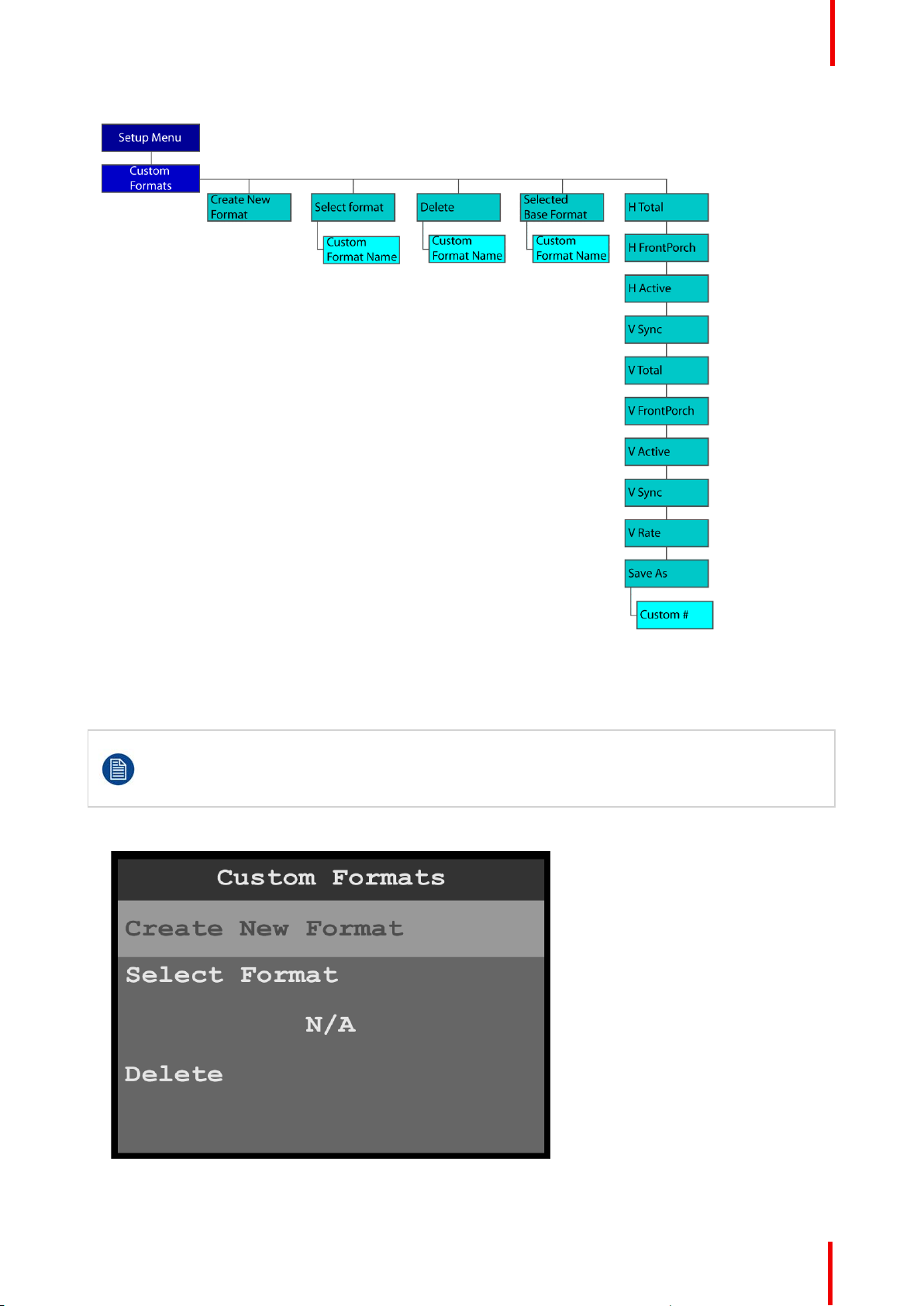
Menu orientation
Image 6-103: Custom Formats menu tree: with custom formats
Create New Format
To create a custom format…
Prior to creating a custom format or modifying an existing format, users should be familiar with how
the adjustments they are making may affect the video format. The user should use a timing
calculator to determine the correct numbers for timing. Incorrect settings can cause unstable or
asynchronous video output.
1. Select Create New Format on the Custom Formats menu.
Image 6-104: Custom Formats menu: Create New Format
R5906167 /00 ImagePRO–4K Video Processor
89
Page 90
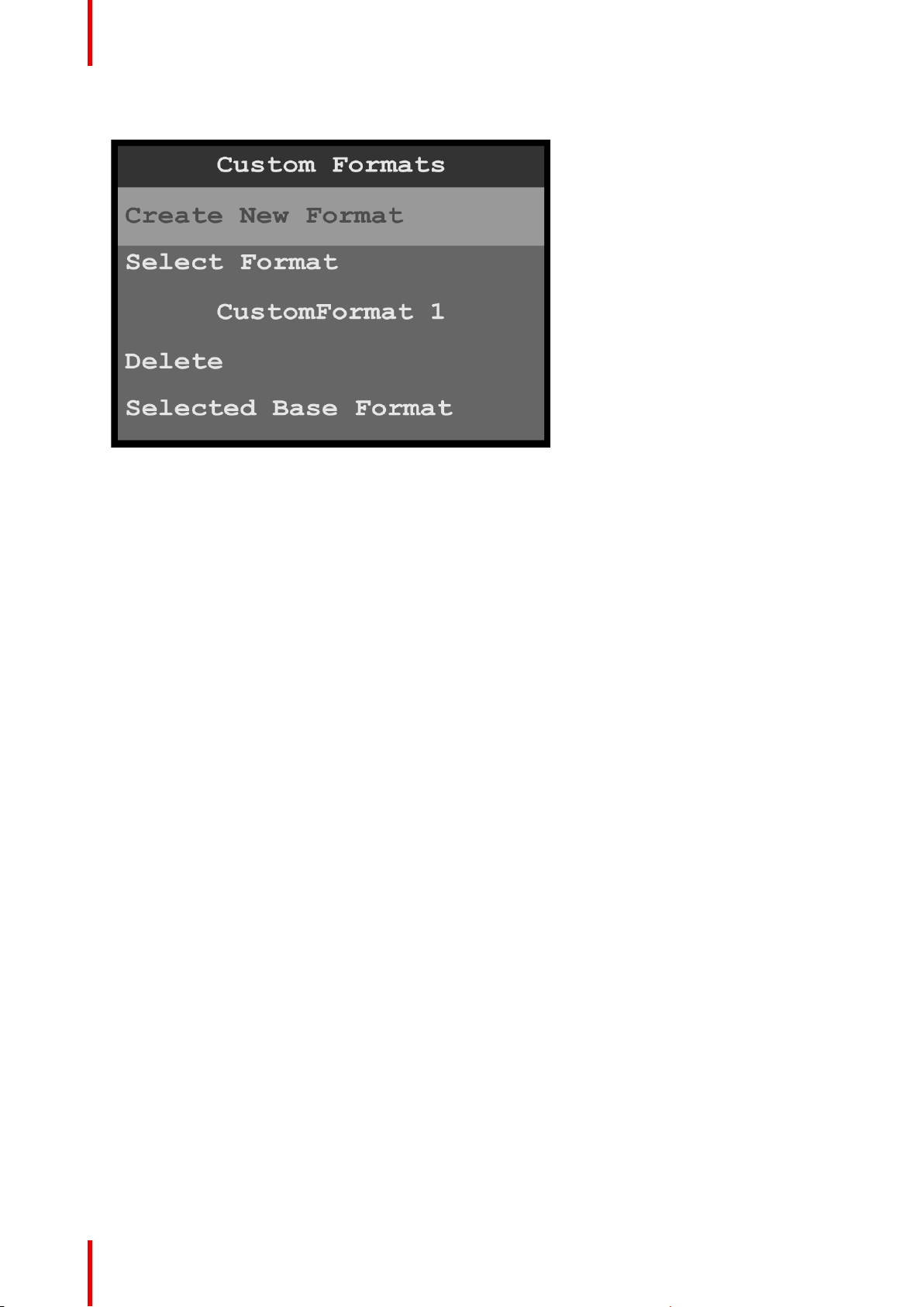
Menu orientation
After a custom format has been created, the system updates the Custom Formats menu.
Image 6-105: Custom Formats menu: Created format
Select Format now shows the name of the first created custom format. More submenus are available
below the Delete submenu. The additional submenus are:
• Selected Base Format—Name of the selected base format
• H Total—Total pixel count per line
• H FrontPorch—The offset between the end of the active area and the beginning of H sync
• H Active—The horizontal size in pixels of the active area
• H Sync—H sync width in pixels
• V Total—Total line count per frame
• V FrontPorch—The offset in lines between the end of the output active area and the beginning of V
sync
• V Active—The vertical size of the output active area
• V Sync—V sync width in lines
• V Rate—Vertical frame rate in frames per second
• Save As—New custom format name
Select Format
To select a format…
1. Scroll to and select Select Format.
Once Select Format is selected, the highlight bar turns from gray to cyan. Turning the adjust knob scrolls
through the available custom formats.
90
R5906167 /00 ImagePRO–4K Video Processor
Page 91
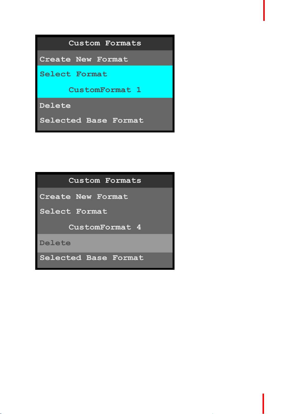
Image 6-106: Custom Formats menu: Select Format
2. Scroll through and select the desired custom format, for example CustomFormat 4.
Delete
1. Scroll to and select Delete, to delete the selected format.
Menu orientation
Image 6-107: Custom Formats menu: Delete
The system displays a message that asks if you really want to delete the custom format.
R5906167 /00 ImagePRO–4K Video Processor
91
Page 92
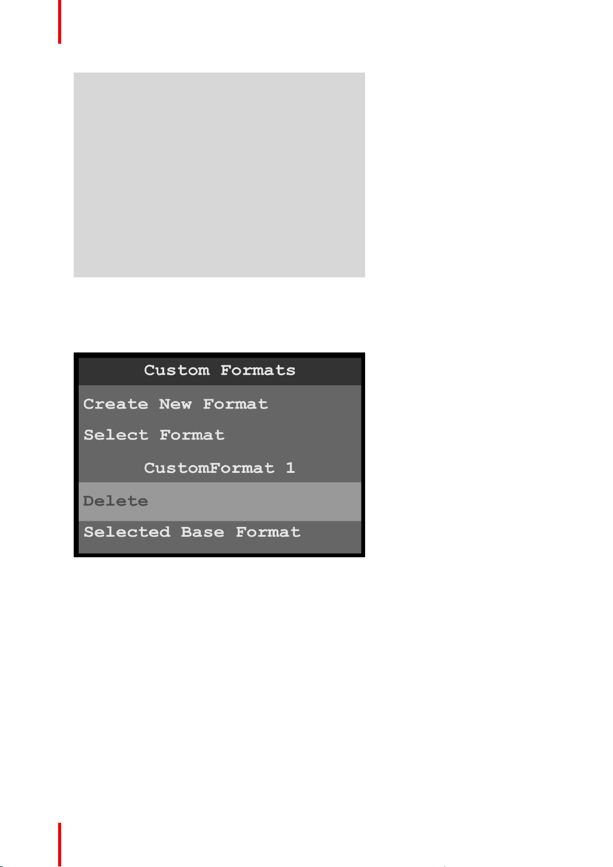
Menu orientation
Image 6-108: Delete message
2. Select Yes to delete the selected custom format.
Select No to keep the custom format.
Once the custom format has been deleted, the system returns to the Custom Formats menu, and “Select
Format” shows the first created custom format (or “N/A,” if no custom formats are available).
Image 6-109: Custom Formats menu: Deleted format
Selected Base Format
Any custom format can serve as a base format for another custom format. Once a selected base format is
assigned to a custom format, the custom format can be adjusted further.
To select a base format…
1. Scroll to and select Selected Base Format.
Once Select Format is selected, the highlight bar turns from gray to cyan. Turning the adjust knob scrolls
through the available custom formats.
92
R5906167 /00 ImagePRO–4K Video Processor
Page 93
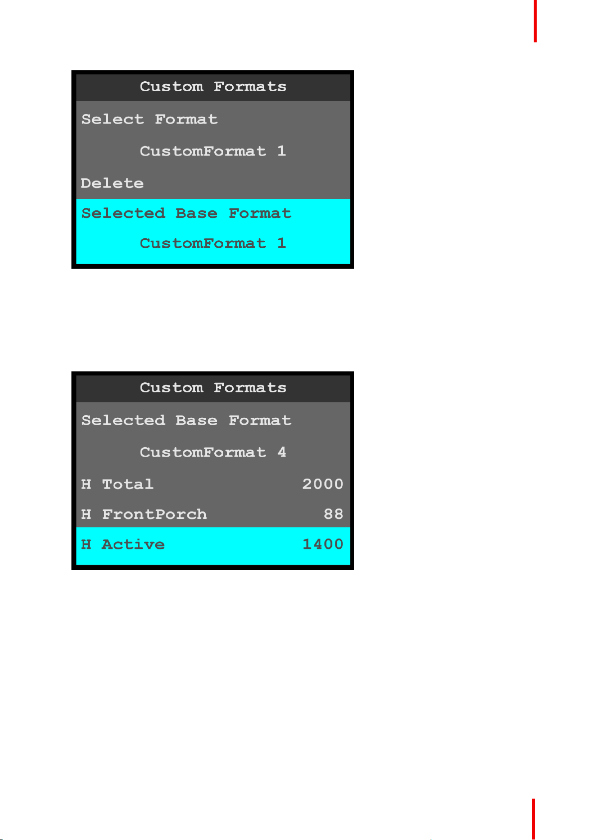
Menu orientation
Image 6-110: Custom Formats menu: Selected Base Format
H Total through V Rate
To adjust the properties of a custom format…
1. Scroll to and select the desired property, for example H Active.
Once the property is selected, the highlight bar for that property turns from gray to cyan. Turning the adjust
knob scrolls through the available values for that property.
Image 6-111: Custom Formats menu: H Active
2. Turn the adjust knob clockwise to increase—or counter-clockwise to decrease—the value of the selected
property.
Save As
If after adjusting the properties of a custom format you do not wish to overwrite that custom format with the
new properties, use Save As to save the adjusted custom format with a different name.
After adjusting the properties of a custom format…
1. Scroll to and select Save As.
Once Save As is selected, the highlight bar turns from gray to cyan, and the first character of the custom
format name is highlighted in green.
R5906167 /00 ImagePRO–4K Video Processor
93
Page 94
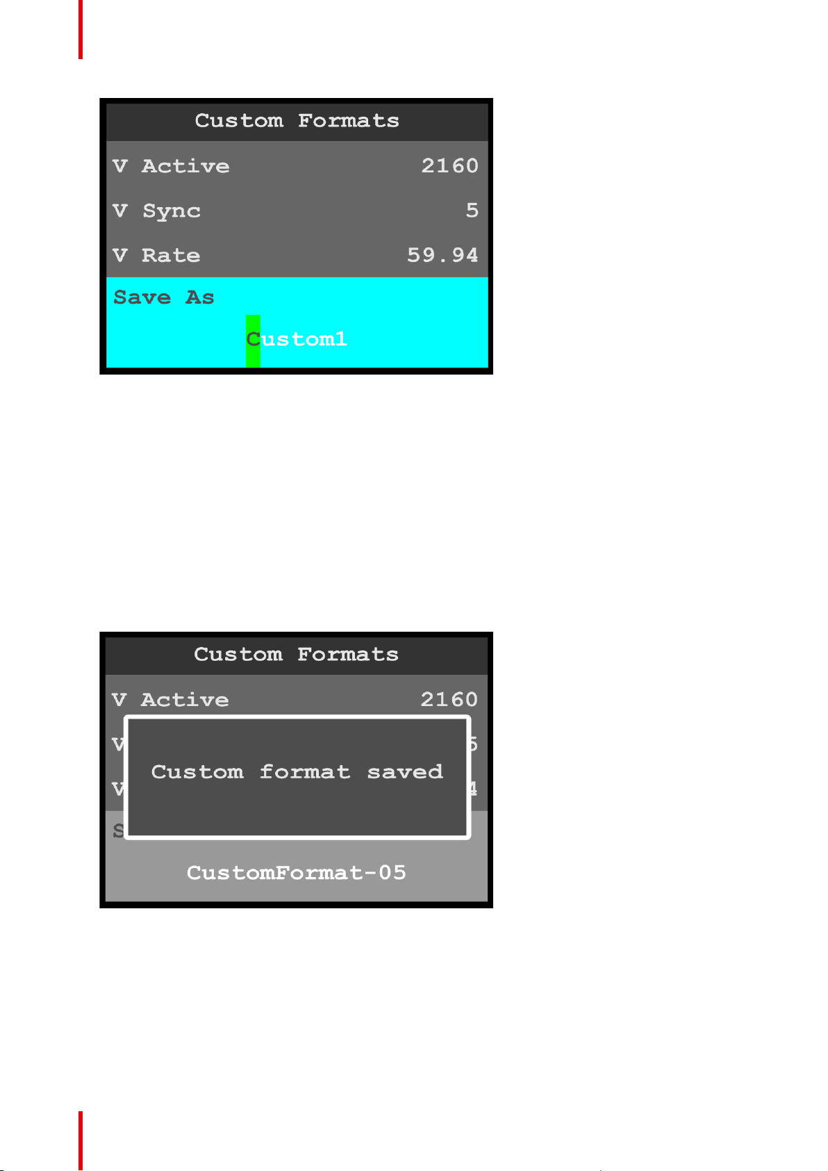
Menu orientation
Image 6-112: Custom Formats menu: Save As
2. Use the adjust knob to adjust the first character of the custom format name, and press the adjust knob
when the desired character is reached.
The available characters are:
• A – Z
• a – z
• 0 – 9
• - (hyphen)
• . (period)
• / (slash)
3. Repeat Step 2 for each character of the custom format name.
The custom format name may have up to 21 characters.
4. Press the adjust knob, once you have entered the new name for the custom format.
The system displays a message that says that the custom format has been saved.
Image 6-113: Custom Formats menu: Save As
How to adjust a format
1. Scroll to and select Select Format.
2. Scroll through and select the desired format name.
3. Scroll through, select, and adjust the desired format properties, for example H Active and V Active.
4. If you do not wish to overwrite the currently selected format, scroll to and select Save As, and give the
adjusted format a new name.
94
R5906167 /00 ImagePRO–4K Video Processor
Page 95
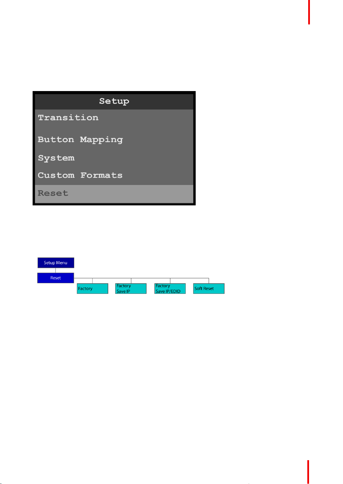
6.10 Reset menu
General
This section provides information about the Reset menu.
To enter the Reset menu from the System menu, scroll to and select Reset.
Menu orientation
Image 6-114: Setup menu: Reset
Use the Reset menu to perform a factory reset.
Reset menu tree
Refer to Image 6-115 for an illustration of the Reset menu tree.
Image 6-115: Reset menu tree
Factory reset
1. Press the adjust knob to select Reset.
R5906167 /00 ImagePRO–4K Video Processor
95
Page 96
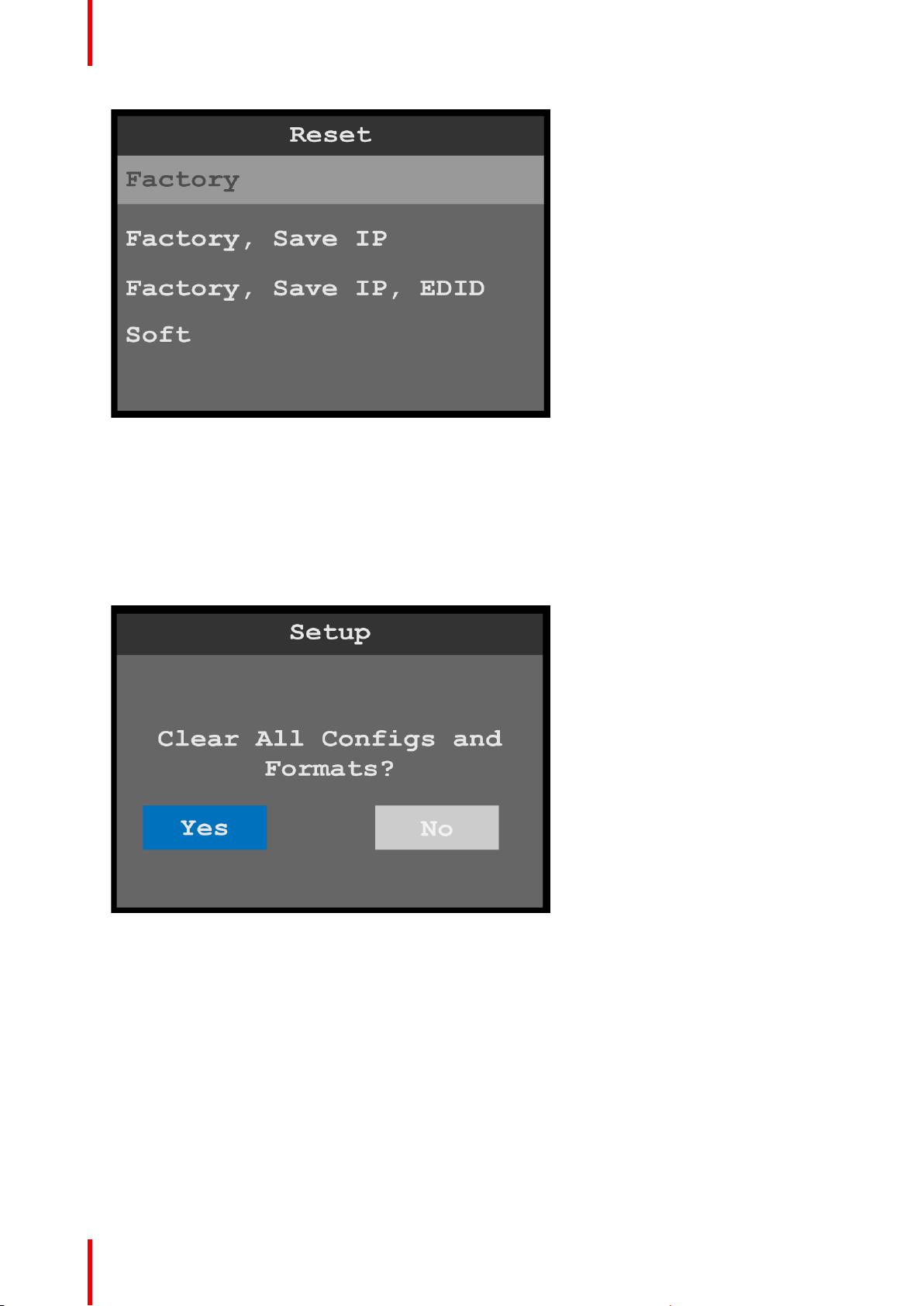
Menu orientation
Image 6-116: Reset menu: Factory
2. Select the type of reset to perform, for example, Factory.
• Factory restores all default system configurations.
• Factory, Save IP restores all default system configurations, except that it saves the current IP address.
• Factory, Save IP, EDID restores all default system configurations, except that it saves the current IP
address and EDID settings.
• Soft keeps the user settings.
The system displays a screen that asks you to confirm that you want to clear all configurations and
formats.
3. Select Yes.
96
Image 6-117: Reset confirmation
The system resets, and while resetting it displays a progress bar.
R5906167 /00 ImagePRO–4K Video Processor
Page 97
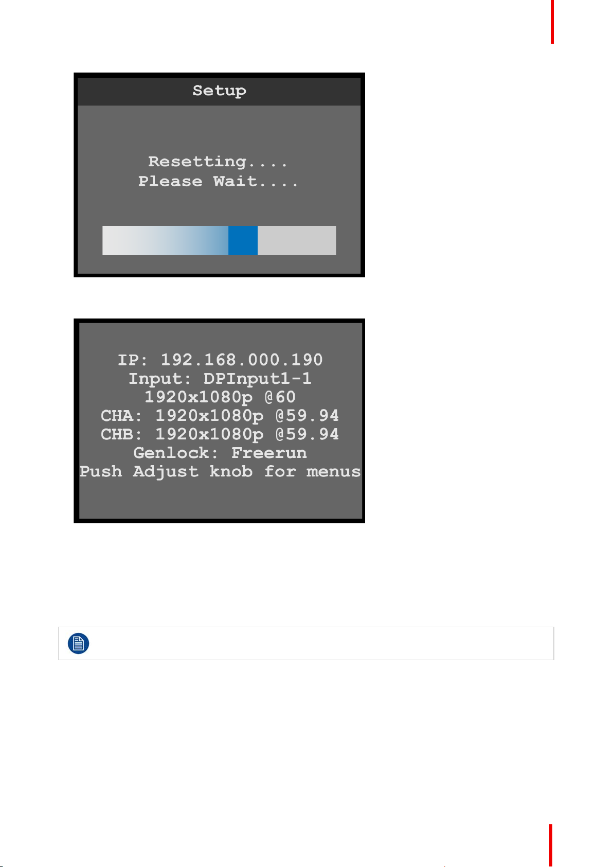
Image 6-118: Reset progress bar
When the system has been reset, the system displays a status screen.
Menu orientation
Image 6-119: Status after reset
6.11 Firmware upgrade menu
General
This section provides information about the Firmware upgrade menu.
Refer to “Upgrading firmware”, page 111 for instructions on performing a firmware upgrade.
To enter the Firmware upgrade menu from the Setup menu, scroll to and select Firmware upgrade.
Firmware upgrade menu tree
Refer to Image 6-120 for an illustration of the Firmware upgrade menu tree.
R5906167 /00 ImagePRO–4K Video Processor
97
Page 98
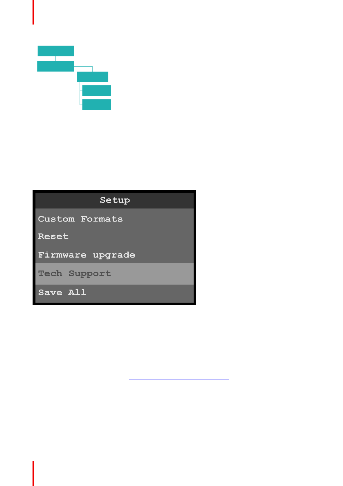
Menu orientation
Image 6-120: Firmware upgrade menu tree
6.12 Tech Support menu
General
The Tech Support menu shows software version and operating system version for your ImagePRO–4K and
provides Customer Support contact information.
To enter the Tech Support menu from the Setup menu, scroll to and select Tech Support.
Image 6-121: Setup menu: Tech Support
Use the Custom Formats menu to create custom formats to match different output devices.
Tech Support
1. Scroll to and select Tech Support.
The system displays the software version and operating system version for your ImagePRO–4K and
provides the following Customer Support contact information.
• Phone: 866-374-7878
• Customer Support URL: barco.com/en/esupport
• BarcoFolsomIP YouTube URL: www.youtube.com/user/BarcoFolsomIP
98
R5906167 /00 ImagePRO–4K Video Processor
Page 99
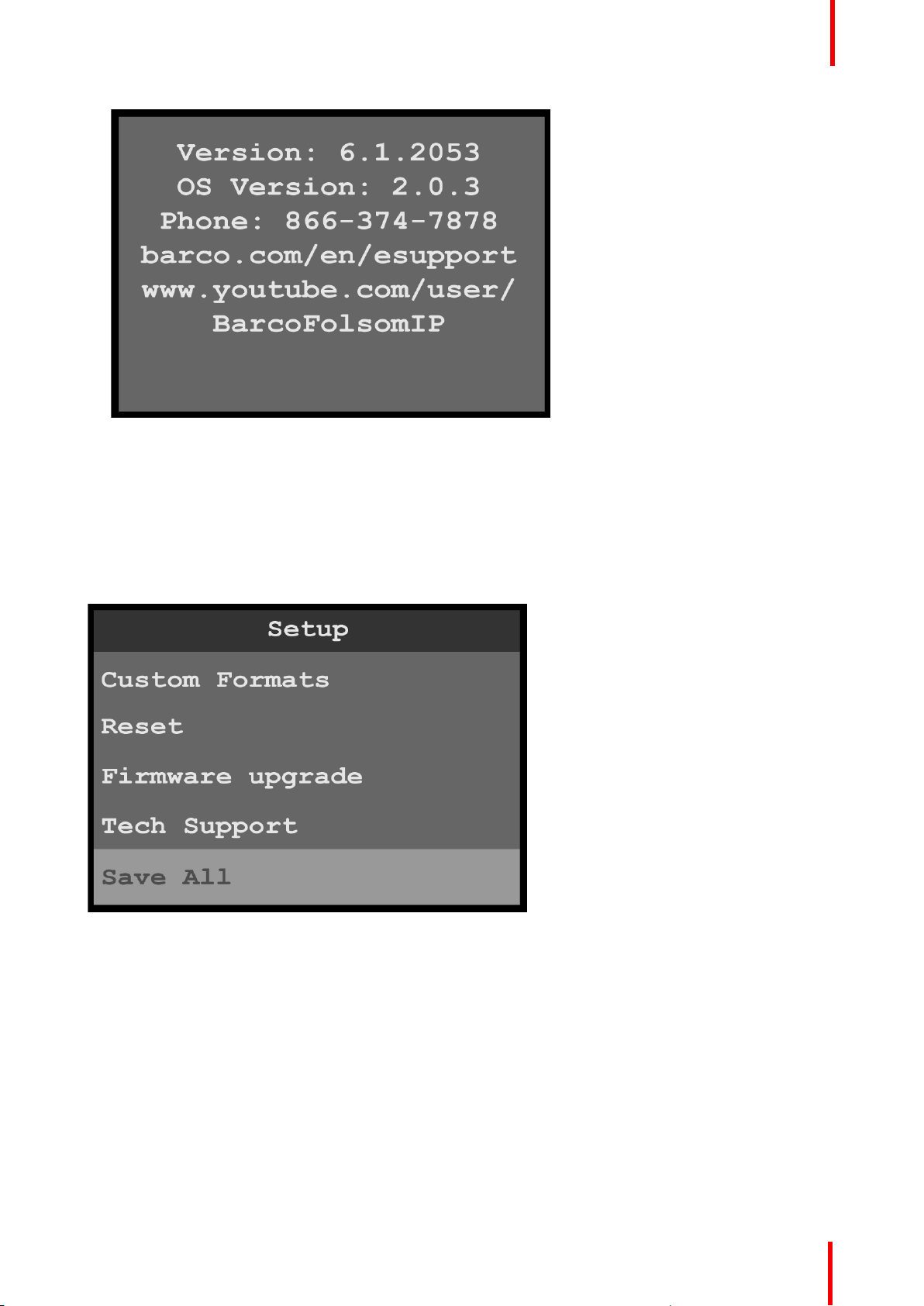
Image 6-122: Tech Support menu
6.13 Save All menu
Menu orientation
General
The Save All menu allows the operator to save all system settings.
To enter the Save All menu from the Setup menu, scroll to and select Save All.
Image 6-123: Setup menu: Save All
Use the Save All menu to save all of the system settings.
Save All
1. Scroll to and select Save All.
The system displays the message “Saved settings file successfully.”
R5906167 /00 ImagePRO–4K Video Processor
99
Page 100

Menu orientation
Image 6-124: Saved settings message
2. Click on OK.
The system saves the settings file and returns to the Setup menu.
100
R5906167 /00 ImagePRO–4K Video Processor
 Loading...