

Page 1
HDX 4K
R5906070/09
09/04/2018
User guide
Page 2

Product revision
Software version: 1.5.x
Barco NV
Beneluxpark 21, 8500 Kortrijk, Belgium
Phone: +32 56.23.32.11
Fax: +32 56.26.22.62
Support: www.barco.com/en/support
Visit us at the web: www.barco.com
Registered address: Barco NV
President Kennedypark 35, 8500 Kortrijk, Belgium
Phone: +32 56.23.32.11
Fax: +32 56.26.22.62
Support: www.barco.com/en/support
Visit us at the web: www.barco.com
Printed in Belgium
Page 3

Copyright ©
All rights reserved. No part of this document may be copied, reproduced or translated. It shall not otherwise be recorded, transmitted or
stored in a retrieval system without the prior written consent of Barco.
Changes
Barco provides this manual ’as is’ without warranty of any kind, either expressed or implied, including but not limited to the implied warranties or merchantability and fitness for a particular purpose. Barco may make improvements and/or changes to the product(s) and/or the
program(s) described in this publication at any time without notice.
This publication could contain technical inaccuracies or typographical errors. Changes are periodic
publication; these changes are incorporated in new editions of this publication.
The latest edition of Barco manuals can be downloaded from the Barco web site w
h
ttps://www.barco.com/en/signin.
ww.barco.com or from the secured Barco web site
ally made to the information in this
Trademarks
Brand and product names mentioned in this manual may be trademarks, registered trademarks or copyrights of their respective holders.
All brand and product names mentioned in this manual serve as comments or examples and are not to be understood as advertising for
the products or their manufacturers.
Guarantee and Compensation
Barco provides a guarantee relating to perfect manufacturing as part of the legally stipulated terms of guarantee. On receipt, the purchaser
must immediately inspect all delivered goods for damage incurred during transport, as well as for material and manufacturing faults Barco
must be informed immediately in writing of any complaints.
The period of guarantee begins on the date of transfer of risks, in the case of special systems and software on the date of commissioning,
at latest 30 days after the transfer of risks. In the event of justifie
at its own discretion within an appropriate period. If this measure proves to be impossible or unsuccessful, the purchaser can demand a
reduction in the purchase price or cancellation of the contract. All other claims, in particular those relating to compensation for direct or
indirect damage, and also damage attributed to the operation o
of the system or independent service, will be deemed invalid provided the damage is not proven to be attributed to the absence of properties
guaranteed in writing or due to the intent or gross negligence or part of Barco.
If the purchaser or a third party carries out modifications or repairs on goods delivered by Barco, or if the goods are handled incorrectly,
in particular if the systems are operated incorrectly or if, after the transfer of risks, the goods are subject to influences not agreed upon in
the contract, all guarantee claims of the purchaser will be rendered invalid. Not included in the guarantee coverage are system failures
which are attributed to programs or special electronic circuitry provided by the purchaser, e.g. interfaces. Normal wear as well as normal
maintenance are not subject to the guarantee provided by Barco either.
The environmental conditions as well as the servicing and maintenance regulations specified in this manual must be complied with by the
customer.
d notice of complaint, Barco can repair the fault or provide a replacement
f software as well as to other services provided by Barco, being a component
Federal Communications Commission (FCC Statement)
This equipment has been tested and found to comply with the limits for a class A digital device, pursuant to Part 15 of the FCC rules.
These limits are designed to provide reasonable protection against harmful interference when the equipment is operated in a commercial
environment. This equipment generates, uses, and can radiate radio frequency energy and, if not installed and used in accordance with
the instruction manual, may cause harmful interference to radio communications. Operation of this equipment in a residential area may
cause harmful interference, in which case the user will be responsible for correcting any interference at his own expense
Changes or modifi cations not expressly approved by the party responsible for compliance could void the user’s authority to operate the
equipment
EMC statements
EN55032/CISPR32 Class A MME (MultiMedia Equipment)
Warning : This equipment is compliant with Class A of CISPR 32. In a residential environment this equipment may cause radio interfer-
ence.
Class A ITE (Information Technology Equipment)
Warning : This is a class A product. In a domestic environment this product may cause radio interference in which case the user may be
required to take adequate mea
sures.
Page 4

Page 5

Table of contents
TABLE OF CONTENTS
1. Safety................................................................................................................. 5
1.1 General considerations............................................................................................................... 5
1.2 Important safety instructions ......................................................................................................... 6
1.3 High Brightnessprecautions: Hazard Distance (HD) ............................................................................... 9
1.4 HD for fully enclosed projectionsystems ........................................................................................... 11
1.5 HD in functionof the lens Throw Ratio (TR)........................................................................................ 11
1.6 Important warnings concerning HDX flight cases..................................................................................12
2. Installation preparations ................ .................. ................ ................ ................ .......13
2.1 Installation requirements .. ..........................................................................................................13
2.2 Unpacking the projector .............................................................................................................14
2.3 Initialinspection......................................................................................................................15
2.4 HDX flight case......................................................................................................................16
2.5 Projector configurations .............................................................................................................16
2.6 Projectorair inlets and outlets.......................................................................................................20
2.7 Free downloadof Projector Toolset.................................................................................................20
3. Pulse Remote Control Unit ........... ................ ................ ................ ................ ...........23
3.1 Remotecontrol, battery installation.................................................................................................23
3.2 Remotecontrol, protocol setup .....................................................................................................24
3.3 Remotecontrol, on/offbutton .......................................................................................................24
3.4 Functions ofthe “button pressedindicator”.........................................................................................25
3.5 Displayingand Programming addressesintothe RCU ............................................................................25
3.6 Using the XLR connector of the RCU...............................................................................................25
3.7 Using the mini-jack connector of the RCU. .........................................................................................26
3.8 Silicone protection sleeve for the RCU (optional) ..................................................................................26
4. Physical Installation ..............................................................................................29
4.1 Connecting the projector with the power net .......................................................................................29
4.2 Alignment of a table mounted projector. . . .. ........................................................................................30
4.3 Mounting the bottom carry handler .................................................................................................30
4.4 Mounting the top carry handler......................................................................................................32
4.5 Suspension of the projector with rigging clamps ...................................................................................33
4.6 Alignment of a ceiling mounted projector . . . ........................................................................................35
5. Lenses & Lens selection .........................................................................................37
5.1 Availablelenses .....................................................................................................................37
5.2 Lens selection .......................................................................................................................38
5.3 Lens installation .....................................................................................................................39
5.4 Lens removal ........................................................................................................................41
5.5 Lens safety cable . .. .................................................................................................................41
5.6 Scheimpflug adjustment.............................................................................................................44
6. Input & Communication..........................................................................................49
6.1 Introduction ..........................................................................................................................49
6.2 Removal of an input board ..........................................................................................................49
6.3 Installation of an input board or a communication board...........................................................................51
6.4 Input source connections – Quad combo input Mark II ............................................................................52
6.5 Input source connections – Quad combo input Mk I ...............................................................................56
6.6 Input source connections – Quad DP 1.2 Input board .. ...........................................................................59
6.7 Communication connections ........................................................................................................60
6.8 LEDand Buttonindicationchart ....................................................................................................62
7. WiFi & GSM Module...................... ................ ................ ................ ................ .........65
7.1 Compliance FCC ....................................................................................................................65
7.2 Compliance IC.......................................................................................................................65
7.3 Installation of the WiFi module ......................................................................................................66
7.4 Installation ofthe GSM module .....................................................................................................69
8. Getting Started...................... ................ ................ ................ ................ ............... 73
8.1 Functionality overview...............................................................................................................73
8.2 Power onprojector ..................................................................................................................74
8.3 Switching to standby ................................................................................................................76
8.4 Power off projector ..................................................................................................................76
8.5 Using the RCU.......................................................................................................................77
8.6 ProjectorAddress....................................................................................................................78
8.6.1 Controlling the projector ......................................................................................................78
8.7 Quick setupvia Direct access.......................................................................................................79
8.8 Software update .....................................................................................................................80
9. Graphic User Interface (GUI) ....................................................................................83
9.1 Overview.............................................................................................................................83
9.2 Navigation ...........................................................................................................................83
R5906070 HDX 4K 09/04/2018
1
Page 6

Table of contents
9.3 Test Patterns.........................................................................................................................84
10. GUI – Source ............ ................ ................ ................ ................ ................ ...........87
10.1 Displaying a single source ..........................................................................................................87
10.2 Displaying multiplesources: Stitched layouts......................................................................................87
10.3 Connector Settings ..................................................................................................................89
11. GUI – Image ........................................................................................................91
11.1 Setting image levels manually ......................................................................................................91
11.2 Adjusting the sharpness.............................................................................................................93
11.3 Adjusting the gamma correction ....................................................................................................93
11.4 P7 Realcolor.........................................................................................................................94
11.5 Setting the output resolution ........................................................................................................96
11.6 HDR – Perceptual Quantizer (PQ) ..................................................................................................97
12. GUI – Installation ..................................................................................................99
12.1 Configuring the lens,zoom-focus...................................................................................................99
12.2 Configuring the lens,shift ...........................................................................................................99
12.3 Configuring the lens,highcontrast.................................................................................................100
12.4 Orientation..........................................................................................................................101
12.5 Warping.............................................................................................................................102
12.5.1 About warping................................................................................................................102
12.5.2 Warping – On/Off ............................................................................................................102
12.5.3 Warping – Screen Size ......................................................................................................102
12.5.4 Warping – 4 corners adjustment.............................................................................................104
12.5.5 Warping – Bow...............................................................................................................105
12.5.6 Warping – Warp files.........................................................................................................108
12.5.7 Warping – Latency control in a multi projectorsetup .......................................................................109
12.6 Blending.............................................................................................................................110
12.6.1 Blend & Mask ................................................................................................................111
12.6.2 Black level adjustment.......................................................................................................113
12.6.3 Black Level Files.............................................................................................................114
12.6.4 Blend Files ...................................................................................................................115
12.7 Lampillumination...................................................................................................................116
12.8 3D projection........................................................................................................................117
12.8.1 Active Stereo & Passive Stereo .............................................................................................117
12.8.2 Setup process 3Dprojection ................................................................................................118
12.8.3 Connection possibilities......................................................................................................118
12.8.4 Choosing the desired Display Setup ........................................................................................119
12.8.5 3D emitterSetup............................................................................................................. 120
13. GUI – System Settings.......................................................................................... 121
13.1 Communication, LAN setup ........................................................................................................121
13.1.1 Introduction to a Network connection .......................................................................................121
13.1.2 Wired IP address set up .....................................................................................................122
13.2 GSM configuration..................................................................................................................123
13.3 IR control............................................................................................................................124
13.3.1 Broadcast address .. . ........................................................................................................124
13.3.2 Projector address ............................................................................................................125
13.3.3 IR sensors....................................................................................................................125
13.4 Setting a customprojector name...................................................................................................126
13.5 Themes .............................................................................................................................127
13.6 Service Menu .......................................................................................................................127
13.6.1 Service – Color...............................................................................................................127
13.6.2 Service – Statistics...........................................................................................................128
13.6.3 Lens Calibration..............................................................................................................129
13.6.4 Flexbrightness...............................................................................................................130
13.7 Lens features .......................................................................................................................131
13.8 Controlling the backlightoftheLCD Display ......................................................................................132
13.9 Reset................................................................................................................................132
14. GUI – Test Patterns................. ................ ................ ................ ................ ............. 135
14.1 Internaltestpatterns................................................................................................................135
14.2 Outputtestpatterns ................................................................................................................135
15. Status menu......... ................ ................ ................ ................ ................ ............. 137
15.1 Status menu overview..............................................................................................................137
16. Maintenance...................................................................................................... 139
16.1 Cleaning the lens .. .................................................................................................................139
16.2 Cleaning the exterior of the projector ..............................................................................................139
17. Servicing.......................................................................................................... 141
17.1 Removal of the front cover.........................................................................................................141
17.2 Mounting the front cover . . . ........................................................................................................143
17.3 Removal of the lamp cover.........................................................................................................144
17.4 Mounting the lamp cover .. .........................................................................................................145
2
R5906070 HDX 4K 09/04/2018
Page 7

Table of contents
17.5 Removal of the lamp house ........................................................................................................146
17.6 Installation of the lamp house ......................................................................................................147
17.7 Replacement of the high density dust filter........................................................................................148
17.8 Remove and clear metal front filter ................................................................................................149
A. Specifications ........ ................ ................ ................ ................ ................ ............. 151
A.1 Specifications ofthe HDX-4K12 ...................................................................................................151
A.2 Specifications ofthe HDX-4K14 ...................................................................................................152
A.3 Specifications ofthe HDX-4K20FLEX.............................................................................................153
A.4 Dimensionsof a HDX...............................................................................................................155
A.5 Technical Regulations ..............................................................................................................155
B. Stacking HDX projectors ........................................................................................ 157
B.1 Mount stacking points ..............................................................................................................157
B.2 StackingHDX projectors ...........................................................................................................157
B.3 Aligning stacked HDX projectors...................................................................................................160
C. Environmental Information .... ................ ................ ................ ................ ................ . 163
C.1 Disposal information................................................................................................................163
C.2 Turkey RoHS compliance ..........................................................................................................164
C.3 Contact information.................................................................................................................164
C.4 Download Product Manual .........................................................................................................164
Glossary .......... ................ ................ ................ ................ ................ ................ ..... 165
Index............... ................ ................ ................ ................ ................ ................ ..... 167
R5906070 HDX 4K 09/04/2018 3
Page 8

Table of contents
4 R5906070 HDX 4K 09/04/2018
Page 9
1. SAFETY
About this chapter
Read this chapter attentively. It contains important information to prevent personal injury while installing and using a HDX projector.
Furthermore, it includes several cautions to prevent damage to the HDX projector. Ensure that you understand and follow all safety
guidelines, safety instructions and warnings mentioned in this chapter before installing the HDX projector. After this chapter, additional “warnings” and “cautions” are given depending on the installation procedure. Read and follow these “warnings” and “cautions”
as well.
Clarification of the term “HDX” us ed in this document
When referring in this document to the term “HDX” means that the content is applicable for following Barco products:
• HDX 4K
• HDX 4K12
• HDX 4K14
• HDX 4K20 FLEX
Barco provides a guarantee relating to perfect manufacturing as part of the legally stipulated terms of guarantee. Observing the specification mentioned in this chapter is critical for projector performance. Neglecting
this can result in loss of warranty.
1. Safety
1.1 General considerations
WARNING: Ensure you understand and follow all the safety guidelines, safety instructions, warnings and
cautions mentioned in this manual.
WARNING: Be aware of suspended loads.
WARNING: Wear a hard hat to reduce the risk of personal injury.
WARNING: Be careful while working with heavy loads.
WARNING: Mind your fingers while working with heavy loads.
CAUTION: High p ressure lamp may explode if improperly handled.
General safety i nstructions
• Before operating this equipment please read this manual thoroughly and retain it for future reference.
• Installation and preliminary adjustments should be performed by qualified Barco personnel or by authorized Barco service dealers.
• All warnings on the projector and in the documentation manuals should be adhered to.
• All instructions for operating and use of this equipment must be followed precisely.
• All local installation codes should be adhered to.
R5906070 HDX 4K 09/04/2018
5
Page 10

1. Safety
Notice on safety
This equipment is built in accordance with the requirements of the international safety standards IEC60950-1, EN60950-1,
UL60950-1 and CAN/CSA C22.2 No.60950-1, which are the safety standards of information technology equipment including
electrical business equipment. These safety standards impose important requirements on the use of safety critical components,
materials and insulation, in order to protect the user or operator against risk of electric shock and energy hazard and having access
to live parts. Safety standards also impose limits to the internal and external temperature rises, radiation levels, mechanical stability
and strength, enclosure construction and protection against the risk of fire. Simulated single fault condition testing ensures the
safety of the equipment to the user even when the equipment’s normal operation fails.
Users definition
Throughout this manual, the term SERVICE PERSONNEL refers to persons having appropriate technical training and experience
necessary to be knowledgeable of potential hazards to which they are exposed (including, but not limited to HIGH VOLTAGE ELECTRIC and ELECTRONIC CIRCUITRY and HIGH BRIGHTNESS PROJECTORS) in performing a task, and of measures to minimize
the potential risk to themselves or other persons. The term USER and OPERATOR refers to any person other than SERVICE PERSONNEL, AUTHORIZED to operate professional projection systems.
The HDX projector is intended "FOR PROFESSIONAL USE ONLY" by AUTHORIZED PERSONNEL familiar with potential hazards
associated with high voltage, high intensity light beams, ultraviolet exposure and
associated circuits. Only qualified SERVICE PERSONNEL, knowledgeable of such risks, are allowed to perform service functions
inside the product enclosure.
high temperatures generated by the lamp and
1.2 Important safety instructions
To prevent the risk of electrical shock
• This product should be operated from a mono phase AC powe
• This apparatus must be grounded (earthed) via the supplied 3 conductor AC power cable. If none of the supplied power cables
are the correct one, consult your dealer.
If you are unable to insert the plug into the outlet, contact your electrician to replace your obsolete outlet. Do not defeat the
purpose of the grounding-type plug.
• Do not allow anything to rest on the power cord. Do not locate this product where persons will walk on the cord. To disconnect
the cord, pull it out by the plug. Never pull the cord itself.
• Use only the power cord supplied with your device. While appearing to be similar, other power cords have not been safety
tested at the factory and may not be used to power the device. For a replacement power cord, contact your dealer.
• Do not operate the projector with a damaged cord. Replace
Do not operate the projector if the projector has been dropped or damaged - until it has been examined and approved for
operation by a qualified service technician.
• Position the cord so that it will not be tripped over, pulled, or contact hot surfaces.
• If an extension cord is necessary, a cord with a current rating at least equal to that of the projector should be used. A cord rated
for less amperage than the projector may overheat.
• Never push objects of any kind into this product through cabinet slots as they may touch dangerous voltage points or short out
parts that could result in a risk of fire or electrical shock.
• Do not expose this projector to rain or moisture.
• Do not immerse or expose this projector in water or other liquids.
• Do not spill liquid of any kind on this projector.
• Should any liquid or solid object fall into the cabinet, unplug the set and have it checked by qualified service personnel before
resuming operations.
• Do not disassemble this projector, always take it to an authorized trained service person when service or repair work is required.
• Do not use an accessory attachment which is not recommended by the manufacturer.
• Lightning - For added protection for this video product during a lightning storm, or when it is left unattended and unused for long
periods of time, unplug it from the wall outlet. This will prevent damage to the device due to lightning and AC power-line surges.
r source.
the cord.
To prevent personal injury
• Isolate electrically before replacing th
• Caution: High pressure lamp may explode if improperly handled. Refer servicing to qualified service personnel.
• To prevent injury and physical damage, always read this manual and all labels on the system before inserting the lamp casing,
connecting to the wall outlet or adjusting the projector.
• To prevent injury, take note of the weight of the projector. Minimum 2 persons are needed to carry the projector.
• To prevent injury, ensure that the lens and all covers are correctly installed. See installation procedures.
• Warning: high intensity light beam. NEVER look into the lens ! High luminance could result in damage to the eye.
• Warning: e xtremely high brightness lamps: This projector uses extremely high brightness lamps. Never attempt to look
directly into the lens or at the lamp. If the projection distance is less than 6 meter, any person needs to be at least 4 meters
away from the projected image. Avoid close range refl ection of the projected image on any reflecting surface (such as glass,
metal, …) . When operating the projector, we strongly recommend wearing suitable safety glasses.
6
e lamp or lamp house. Caution: Hot lamp (house).
R5906070 HDX 4K 09/04/2018
Page 11

1. Safety
• Before attempting to remove any of the projector’s covers, you must turn off the projector and disconnect from the wall outlet.
• When required to switch off the projector, to access parts inside, always disconnect the power cord from the power net.
• The power input at the projector side is considered as the disconnect device. When required to switch off the projector, to
access parts inside, always disconnect the power cord at the projector side. In case the power input at the projector side is not
accessible (e.g. ceiling mount), the socket outlet supplying the projector shall be installed nearby the projector and be easily
accessible, or a readily accessible general disconnect device shall be incorporated in the fixed wiring.
• Never stack more than 2 HDX projectors in a hanging configuration (truss) and never stack more than 3 HDX projectors in a
base stand confi guration (table mount).
• When using the projector in a hanging configuration, always mount 2 safety cables. See installation manual for the correct use
of these cables.
• Do not place this equipment on an unstable cart, stand, or table. The product may fall, causing serious damage to it and
possible injury to the user.
• It is hazardous to operate without lens or shield. Lenses, shields or ultra violet screens shall be changed if they have become
visibly damaged to such an extent that their effectiveness is impaired. For example by cracks or deep scratches.
• Warning: Protection from ultraviolet radiation: Do not look directly in the light beam. The lamp contained
an intense source of light and heat. One component of the light emitted from this lamp is ultraviolet light. Potential eye and skin
hazards are present when the lamp is energized due to ultraviolet radiation. Avoid unnecessary exposure. Protect yourself and
your employees by making them aware of the hazards and how to protect themselves. Protecting the skin
by wearing tightly woven garments and gloves. Protecting the eyes from UV can be accomplished by wearing safety glasses
that are designed to provide UV protection. In addition to the UV, the visible light from the lamp is intense and should also be
considered when choosing protective eye wear.
• Exposure to UV radiation: Some medications are known to make individuals extra sensitive to UV radiation. The American
Conference of Governmental Industrial Hygienists (ACGIH) recommends occupational UV exposure for an-8 hour day to be
less than 0,1 micro-watts per square centimeters of effective UV radiation. An evaluation of the workplace is advised to assure
employees are not exposed to cumulative radiation levels exceeding these government guidelines. The exposer of this UV
radiation is allowed for only 1 hour per day for maintenance and service persons.
• Cooling liquid circuit. The projector contains a cooling circuit filled with Blue antifreeze diluted (1/3 ethanediol – 2/3 Demi
water).
When the cooling circuit leaks, switch off the device and contact a service technician.
The liquid is not for household use. Keep out of reach of children. Harmful by oral intake. Avoid exposure to pregnant women.
Avoid contact with eyes, skin and clothing. Avoid inhale of the noxious fumes.
• When the projector is mounted above persons, mount always a lens safety cable.
• In case the product malfunctions, power off the unit and contact Barc
w
ww.barco.com/en/support.
o by logging an incident via the support website:
in this product is
can be accomplished
To prevent fire hazard
• Do not place flammable or combustible materials near the projector!
• Barco large screen projection products are designed and manufactured to meet the most stringent safety regulations. This
projector radiates heat on its external surfaces and from ventilation ducts during normal operation, which is both normal and
safe. Exposing flammable or combustible materials into close proximity of this projector could result in the spontaneous ignition
of that material, resulting in a fire. For this reason, it is absolutely necessary to leave an “exclusion zone” around all external
surfaces of the projector whereby no fl ammable or combustible materials are present. The exclusion zone must be not less than
40 cm (16”) for all DLP projectors. The exclusion zone on the lens side must be at least 5 m. Do not cover the projector or the
lens with any material while the projector is in operation. Keep flammable and combustible materials away from the projector at
all times. Mount the projector in a well ventilated area away from sources of ignition and out of direct sun light. Never expose
the projector to rain or moisture. In the event of fire, use sand, CO
electrical fire. Always have service performed on this projector by authorized Barco service personnel. Always insist on genuine
Barco replacement parts. Never use non-Barco replacement parts as they may degrade the safety of this projector.
• Slots and openings in this equipment are p
it from overheating, these openings must not be blocked or covered. The openings should never be blocked by placing the
projector too close to walls, or other similar surface. This projector should never be placed near or over a radiator or heat
register. This projector should not b
• Projection rooms must be well ventilated or cooled in order to avoid build up of heat.
• Let the projector cool down completely before storing. Remove cord from the projector when storing.
• Heat sensitive materials should not be placed in the path of the exhausted air or on the lamp house.
rovided for ventilation. To ensure reliable operation of the projector and to protect
e placed in a built-in installation or enclosure unless proper ventilation is provided.
or dry powder fire extinguishers. Never use water on an
2
R5906070 HDX 4K 09/04/2018
7
Page 12

1. Safety
To prevent projector damage
• This projector has been designed for use with a specific lamp (house) type. See installation instructions for its correct type.
• The air filters of the projector must be cleaned or replaced on regular base (a "clean" booth would be monthly-minimum).
Neglecting this could result in disrupting the air flow inside the projector, causing overheating. Overheating may lead to the
projector shutting down during operation.
• The projector must always be installed in a manner which ensures free flow of air into its air inlets and unimpeded evacuation
of the hot air from its cooling system.
• In order to ensure that correct airflow is maintained, and that the projector complies with Electromagnetic Compatibility (EMC)
requirements, it should always be operated with all of it’s covers in place.
• Slots and openings in the cabinet are provided for ventilation. To ensure reliable operation of the product and to protect it from
overheating, these openings must not be blocked or covered. The openings should never be blocked by placing the product
on a bed, sofa, rug, or other similar surface. This product should never be placed near or over a radiator or heat register. The
device should not be placed in a built-in installation or enclosure unless proper ventilation is provided.
• Ensure that nothing can be spilled on, or dropped inside the projector. If this does happen, switch off
supply immediately. Do not operate the projector again until it has been checked by qualified service personnel.
• Do not block the projector cooling fans or free air movement around the projector. Loose papers or other objects may not be
nearer to the projector than 10 cm (4") on any side.
• Do not use this equipment near water.
• Special care for Laser Beams: Special care should be used when DLP projectors are used in the same room as high power
laser equipment. Direct or indirect hitting of a laser beam on to the lens can severely damage the Digital Mirror Devices
which case there is a loss of warranty.
• Never place the projector in direct sun light. Sun light on the lens can severely damage the Digital Mirror Devices
case there is a loss of warranty.
• Save the original shipping carton and packing material. They will come in handy if you ever have to ship your equipment. For
maximum protection, repack your set as it was originally packed at the factory.
• Unplug this product from the wall outlet before cleaning. Do not use liquid cleaners or aerosol cleaners. Use a damp cloth for
cleaning. Never use strong solvents, such as thinner or benzine, or abrasive cleaners, since these will damage the cabinet.
Stubborn stains may be removed with a cloth lightly dampened with mild detergent solution.
• To ensure the highest optical performance and resolution, the projection lenses are specially treated with an anti-reflective
coating, therefore, avoid touching the lens. To remove dust on the lens, use a soft dry cloth. Do not use a damp cloth, detergent
solution, or thinner.
• Rated maximum ambient temperature, t
• The lamp house shall be replaced if it has become damaged or thermally deformed.
= 40 °C (104 °F).
a
and unplug the mains
TM
in which
TM
in
On servicing
• Do not attempt to service this product yourself, as opening or removing covers may expose you to dangerous voltage potentials
and risk of electric shock.
• Refer all servicing to qualified service personnel.
• Attempts to alter the factory-set internal controls or to change other control settings not specially discussed in this manual can
lead to permanent damage to the projector and cancellation of the warranty.
• Unplug this product from the wall outlet and refer servicing to qualified service technicians under the following conditions:
- When the power cord or plug is damaged or frayed.
- If liquid has been spilled into the equipment.
- If the product has been exposed to rain or water.
- If the product does not operate normally when the operating instructions are followed. Adjust only those controls that are
covered by the operating instructions since improper adjustment of the other controls may result in damage and will often
require extensive work by a qualified technician to restore the product to normal operation.
- If the product has been dropped or the cabinet has been damaged.
- If the product exhibits a distinct change in performance, indicating a need for service.
• Replacement parts: When replacement parts are required, be sure the service technician has used original Barco replacement
parts or authorized replacement parts which have the same characteristics as the Barco original part. Unauthorized substitutions may result in degraded performance and reliability, fire, electric shock or other hazards. Unauthorized substitutions may
void warranty.
• Safety check: Upon completion of any service or repairs to this projector, ask the service technician to perform safety checks
to determine that the product is in proper operating condition.
• Possible explosion hazard: Always keep in mind the caution below:
CAUTION: Xen o n compact arc lamps are highly pressurized. When ignited, the normal operating temperature
of the bulb increases the pressure to a level at which the bulb may explode if not handled in strict accordance
to the manufacturer’s instructions. The bulb is stable at room temperature, but may still explode if dropped or
otherwise mishandled. When ever the lamp house, containing a xenon lamp, has to be dismantled or whenever
the protective container o r cloth has to be removed from the xenon lamp, authorized protective clothing MUST
be wo r n!
8 R5906070 HDX 4K 09/04/2018
Page 13
To prevent battery explosion
• Danger of explosion if battery is incorrectly installed.
• Replace only with the same or equivalent type recommended by the manufacturer.
• For disposal of used batteries, always consult federal, state, local and provincial hazardous waste disposal rules and regulations
to ensure proper disposal.
Safety Data Sheets for Hazardous Chemicals
For safe handling information on chemical products, consult the Safety Data Sheet (SDS). SDSs are available upon request via
safetydatasheets@barco.com.
1.3 High Brightness precautions: Hazard Distance (HD)
HD
Hazard Distance (HD) is the distance measured from the projection lens at which the intensity or the energy per surface
unit becomes lower than the applicable exposure limit on the cornea or on the skin. The light beam is considered (to
be) unsafe for exposure if the distance from a person to the light source is less than the HD.
Restriction Zone (RZ) based on the HD
The HD depends on the amount of lumens produced by the projector and the type of lens installed. See next chapter"HD in function
of the lens Throw Ratio (TR)", page 11.
To protect untrained end users (as cinema visitors, spectators) the installation shall comply with the following installation requirements: Operators shall control access to the beam within the hazard dista
spectators’ eyes from being in the hazard distance. Radiation levels in excess of the limits will not be permitted at any point less than
2.0 meter (SH) above any surface upon which persons other than operators, performers, or employees are permitted to stand or less
than 1.0 meter (SW) lateral separation from any place where such pers
behavior is reasonably foreseeable, the minimum separation height should be greater than or equal to 3.0 meter to prevent potential
exposure, for example by an individual sitting on another individual’s shoulders, within the HD.
These values are minimum values and are based on the guidance provided in IEC 62471-5:2015 section 6.6.3.5.
The installer and user must understand the risk and apply protective measures based upon the hazard distance as indicated on
the label and in the user information. Installation method, separation height, barriers, detection system or other applicable control
measure shall prevent hazardous eye access to the radiation within the hazard distance.
For example, projectors that have a HD greater than 1 m and emit light into an uncontrolled area where persons may be present
should be positioned in accordance with “the fixed projector installation” parameters, resulting in a HD that does not extend into
the audience area unless the beam is at least 2.0 meter above the floor level. In environments where unrestrained behavior is
reasonably foreseeable, the minimum separation height should be greater than or equal to 3.0 meter to prevent potential exposure,
for example by an individual sitting on another individual’s shoulders, within the HD. Sufficiently large separation height may be
achieved by mounting the image projector on the ceiling or through the use of physical barriers.
nce or install the product at the height that will prevent
ons are permitted to be. In environments where unrestrained
1. Safety
RA TH
HD
RA
SH
RZ
SH
Image 1-1
ASideview.
B Top view.
RA Restricted Access location (boot area of projector).
PR Projector.
TH Theater.
RZ Restriction Zone in the theater.
SH Separation Height.
SW S eparation Width.
R5906070 HDX 4K 09/04/2018 9
PR
(B) TOP VIEW(A) SIDE VIEW
TH
HD
SW
SW
SW
RZ
1m
SW
Page 14
1. Safety
Based on national requirements, no person is allowed to enter the projected beam within the zone between the projection lens and
the related hazard distance (HD). This shall be physically impossible by creating sufficient separation height or by placing barriers.
The minimum separation height takes into account the surface upon which persons other than operator, performers or employees
are permitted to stand.
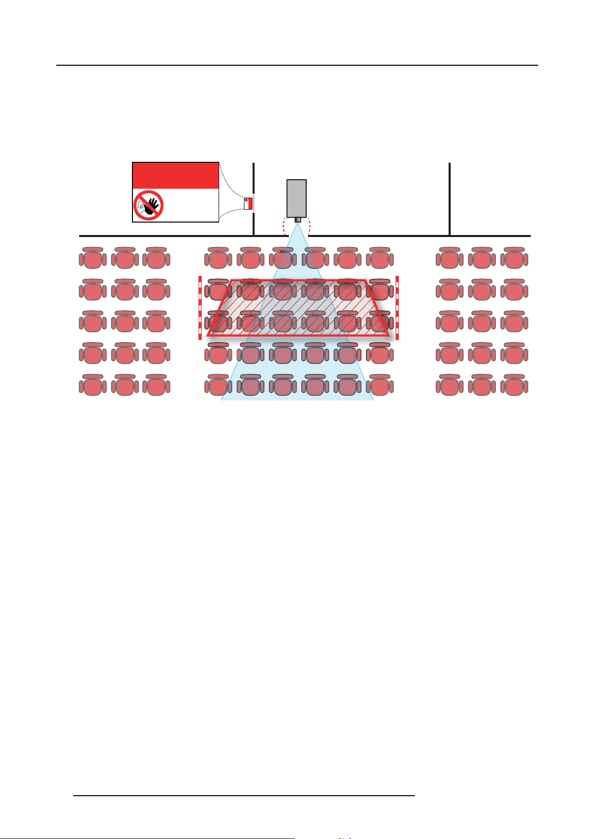
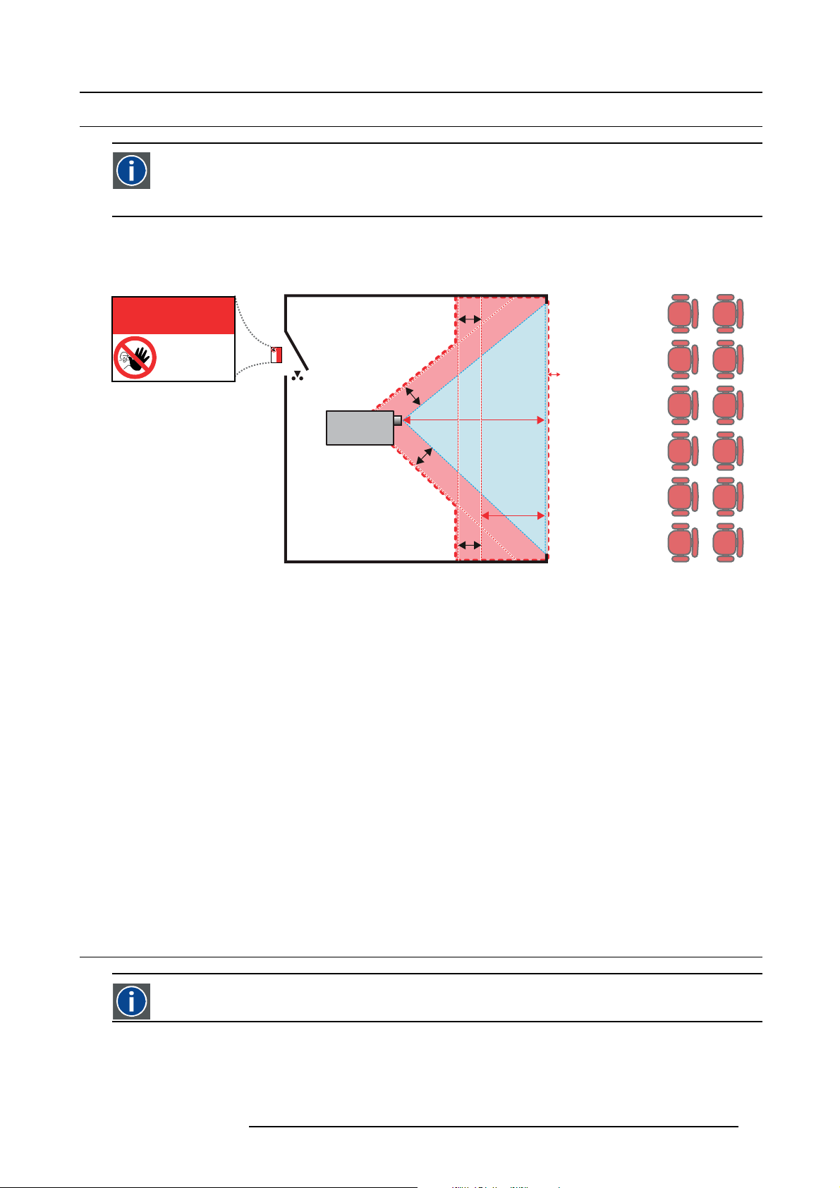
On image 1-2 a typical setup is displayed. It must be verified if these minimum requirements are met. If required a restricted zone
(RZ) in the theater must be established. This can be done by using physical barrier, like a red rope as illustrated in image 1-2.
The restricted area sticker can be replaced by a sticker with only the symbol.
RESTRICTED
AREA
AREA
RESTRICTED
PR
Image 1-2
USA market
For LIPs (Laser Illuminated Projectors) installed in the USA market other restriction zone conditions apply.
Lip’s for installation in restrained environment (cinema theaters) shall be installed at height vertically above the floor such that the
bottom plane of the hazard distance zone shall be no lower than 2.5 meters above the floor. Horizontal clearance to the hazard
distance zone shall be not less than 1 meter.
Lip’s for installations in unrestrained environment (large venues,..) shall be installed at a height vertically above the floor such that
the bottom plane of the Hazard distance Zone shall be no lower than 3 meters above the floor. Horizontal clearance to the hazard
distance zone shall be not less than 2.5 meters. Any human access horizontally to the Hazard Zone, if applicable, shall be restricted
by barriers. If human access is possible in an unsupervised environment, the horizontal or vertical clearances shall be increased to
prevent exposure to the hazard distance zone.
In addition for temporary installations (e.g.: rental and staging, lease, events …) the following requirements apply:
• This product can only be installed by Barco or sold or leased only to valid laser light show variance holders. In other words
our installers are required to have an approved laser light show variance. Such installers may currently hold a valid variance
for production of Class IIIb and IV laser light shows and/or for incorporation of the RG3 LIPs into their shows. Dealers and
distributors are also required to obtain a valid laser light show variance.
• This product shall be located in such a way that all propagating beam paths within the Restriction Zone, and the audience can
be directly observed at all times.
• Effects other than front or rear screen projections shall not be performed.
• Communication shall be maintained with other personnel assisting in surveillance of the LIP projection.
• In the event of any unsafe condition, immediately terminates (or designate the termination) of LIP projection light.
Install one or more readily accessible controls to immediately terminate LIP projection light. The power input at the projector side
is considered as a reliable disconnect device. When required to switch off the projector, disconnect the power cord at the projector
side. In case the power input at the projector side is not accessible (e.g. truss mount), the socket outlet supplying the projector shall
be installed nearby the projector and be easily accessible, or a readily accessible general disconnect device shall be incorporated
in the fi xed wiring.
Laser light shows can be requested via the FDA online eSubmitter portal or via FDA Form FDA Form 3147 referencing to Barco’s
variance approval 2016-V-0144.
10
R5906070 HDX 4K 09/04/2018
Page 15
1.4 HD for fully enclosed projection systems
HD
Hazard Distance (HD) is the distance measured from the projection lens at which the intensity or the energy per surface
unit becomes lower than the applicable exposure limit on the cornea or on the skin. The light beam is considered (to
be) unsafe for exposure if the distance from a person to the light source is less than the HD.
Restriction Zone (RZ) based on the HD
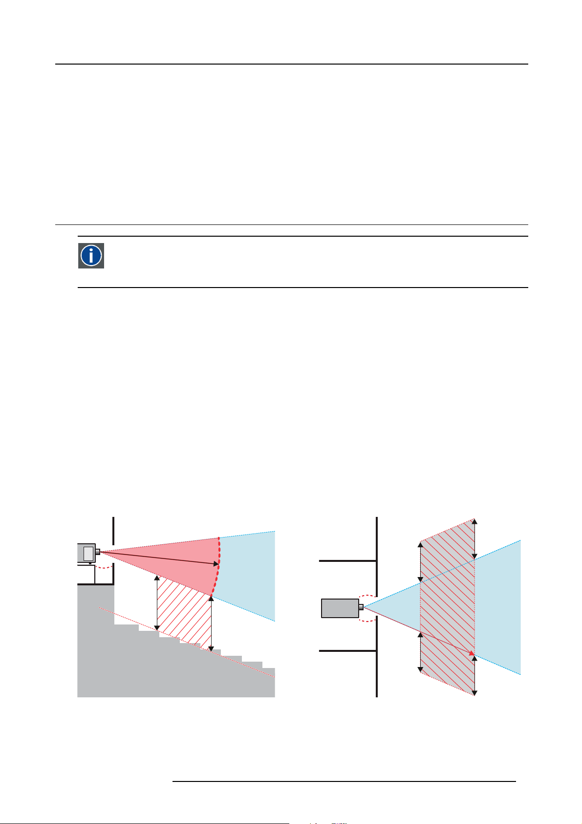
The projector is also suitable for rear projection applications; projecting a beam onto a defuse coated projection screen. As displayed
in image 1-3 two areas should be considered: the restricted enclosed projection area (RA) and the observation area (TH).
1. Safety
RESTRICTED
RA TH
sw
AREA
RESTRICTED
AREA
HDDIFFUSE
RZ
sw
sw
PD
HD
REFLECTION
reflection
); also taking into account a 1 meter lateral
PR
sw
Image 1-3
RA Restricted Access location (enclosed projection area).
PR Projector.
TH Theater (observation area).
RZ Restriction Zone.
PD Projection Distance.
SW Separation Width. Must be minimum 1 meter.
For this type of setup 3 different HD shall be considered:
• HD as discussed in "High Brightness precautions: Hazard Distance (HD)", page 9, relevant for intrabeam exposure.
•HD
reflection
•HD
diffuse
: the distance that has to b
: the relevant distance to be considered while observing the diffuse surface of the rear projection screen.
e kept restrictive related to the reflected light from the rear projection screen.
As described in "High Brightness precautions: Hazard Distance (HD)", page 9, it is mandatory to create a restricted zone within
the beam areas closer than any HD. In the enclosed projection area the combination of two restricted zones are relevant: The
restricted zone of the projected beam toward the screen; taking into account 1 meter Separation Width (SW) from the beam onward.
Combined with the restricted zone related to the rear reflection from the screen (HD
separation.
The HD
projection screen. To determine the HD distance for the used lens and projector model see graphs in chapter "HD in function of the
distance equals 25% of the difference between the determined HD distance and the projection distance to the rear
reflection
lens Throw Ratio (TR)", page 11.
HD
reflection
= 25% (HD – PD)
The light emitted from the screen within the observation shall never exceed the RG2 exposure limit, determined at 10 cm. The
HD
can be neglected if the measured light at the screen surface is below 5000 cd/m² or 15000 LUX.
diffuse
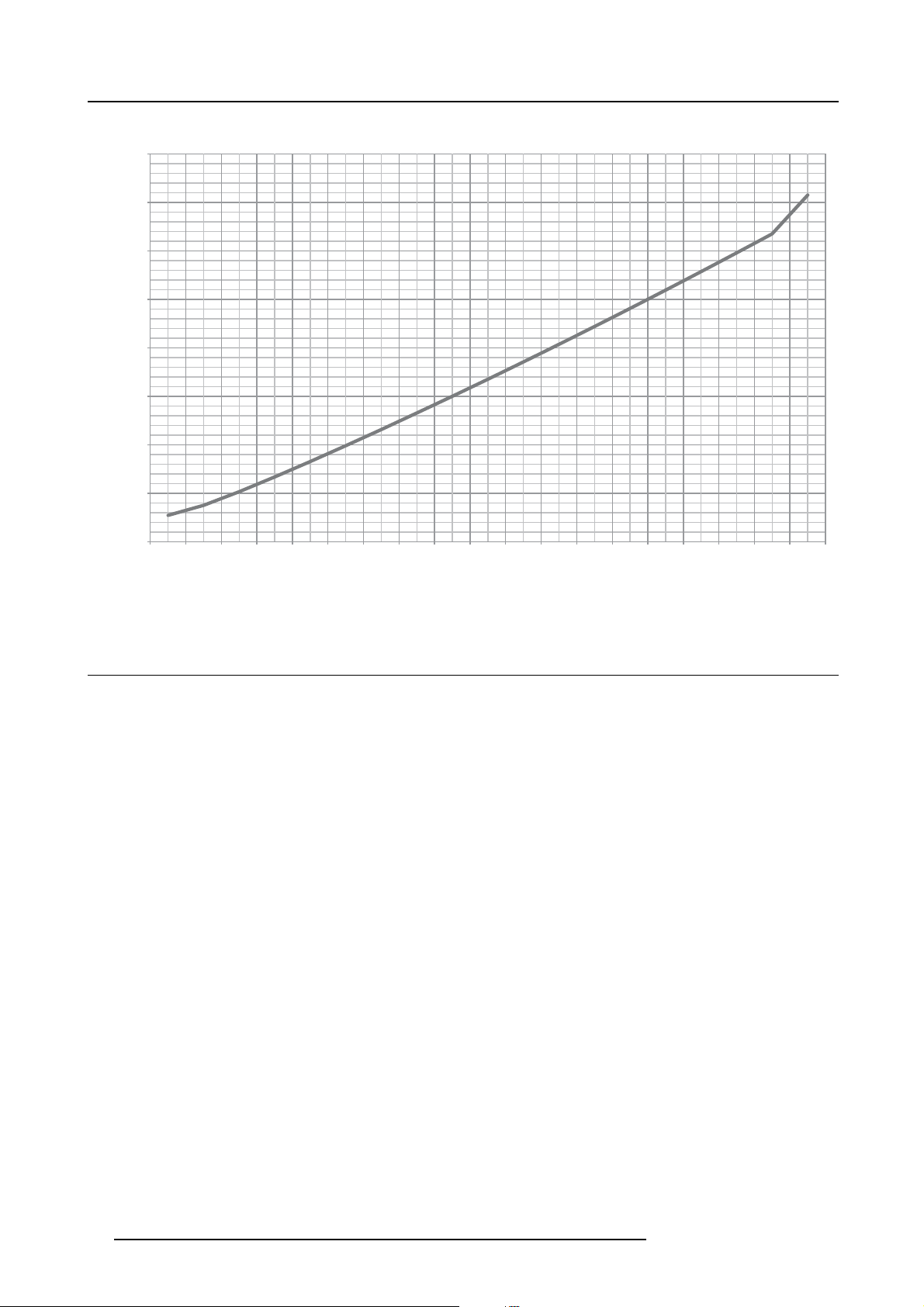
1.5 HD in function of the lens Throw Ratio (TR)
TR (Th r ow Ratio)
The ratio of the distance to the screen (throw) to the screen width.
R5906070 HDX 4K 09/04/2018 11
Page 16
1. Safety
HDX series projector Hazard Distance
8
7
6
5
4
HD [m]
3
2
1
0
0,5 1,0 1,5 2,0 2,5 3,0 3,5 4,0 4,5 5,0 5,5 6,0 6,5 7,0 7,5 8,0 8,5 9,0 10,0
Image 1-4
HD (in meter) in function of the Throw Ratio (TR)
TR
1.6 Important warnings concerning HDX flight cases
Important warnings concerning stacking/transporting HDX rental flight cases
• Stack maximum two (2) HDX rental flight cases high. Never higher.
• Surface on which flight case is standing must be level to ensure that the total load is evenly spread out among the four wheels.
The surface must also be able to support the load safely.
• Before stacking or transporting flight cases, check the wheels and their fixation screws for wear or defects.
• Before stacking or transporting flight cases, check that the four lock handles on each flight case are in good working order and
locked securely.
• When stacked, make sure the wheels of the upper flight case are precisely positioned in the stacking dishes of the flight case
below.
•Stackedflight cases may not be moved. Before stacking, the lower flight case must already be in its final resting position before
placing the second upon it.
• Never stack loaded flight cases in a truck or other transport medium, unless each flight case is rigidly strapped tight.
• In the event of a wheel breaking, flight cases must be rigidly strapped tight to prevent a stack collapsing.
• Use an appropriate forklift to raise flight cases and take the necessary precautions to avoid personnel injury.
12
R5906070 HDX 4K 09/04/2018
Page 17
2. Installation preparations
2. INSTALLATION PREPARATIONS
About this chapter
Read this chapter before installing the HDX projector. It contains important information concerning installation requirements for
the projector, such as minimum and maximum allowed ambient temperature, humidity conditions, required safety area around the
installed projector, required power net, etc.
Furthermore, careful consideration of things such as image size, ambient light level, projector placement and type of screen to use
are critical to the optimum use of the projection system.
Barco provides a guarantee relating to perfect manufacturing as part of the legally stipulated terms of guarantee. Observing the specification mentioned in this chapter is critical for projector performance. Neglecting
this can result in loss of warranty.
Overview
• Installation requirements
• Unpacking the projector
• Initial inspection
• HDX flight case
• Projector configurations
• Projector air inlets and outlets
• Free download of Projector Toolset
2.1 Installation requirements
Environment conditions
Table below summarizes the physical environment in which the HDX may be safely operated or stored.
Environment Operating Non-Operating
Ambient Temperature 10 °C (50 °F) to 40 °C (104 °F) -15°C (5°F) to 60°C (140°F)
Humidity 0% RH to 80% RH Non-condensed 0% RH to 90% RH Non-Condensed
Altitude -60 m (-197 Ft) to 3000 m (9843Ft) -60 m (-197 Ft) to 10000 m (32810 Ft)
Let the projector acclimatize after unpacking. Neglecting this may result in a startup failure of the Light Processor Unit.
Cooling requirements
The projector is fan cooled and must be installed with sufficient space around the projector head, minimum 10 cm (4 inch) to ensure
sufficient air flow. It should be used in an area where the ambient temperature, as measured at the projector air inlet , does not
exceed +40°C (+104°F).
Clean air environment
A projector must always be mounted in a manner which ensures the free flow of clean air into the projectors ventilation inlets. For
installations in environments where the projector is subject to airborne contaminants such as that produced by smoke machines or
similar (these deposit a thin layer of greasy residue upon the projectors internal optics and imaging electronic surfaces, degrading
performance), then it is highly advisable and desirable to have this contamination removed prior to it reaching the projectors clean
air supply. Devices or structures to extract or shield contaminated air well away from the projector are a prerequisite, if this is not a
feasible solution then measures to relocate the projector to a clean air environment should be considered.
Only ever use the manufacturer’s recommended cleaning kit which has been specifically designed for cleaning optical parts, never
use industrial strength cleaners on the projector’s optics as these will degrade optical coatings and damage sensitive optoelectronics
components. Failure to take suitable precautions to protect the projector from the effects of persistent and prolonged air contaminants will culminate in extensive and irreversible ingrained optical damage. At this stage cleaning of the internal optical units will
be noneffective and impracticable. Damage of this nature is under no circumstances covered under the manufacturer’s warranty
and may deem the warranty null and void. In such a case the client shall be held solely responsible for all costs incurred during any
repair. It is the clients responsibility to ensure at all times that the projector is protected from the harmful effects of hostile airborne
particles in the environment of the projector. The manufacturer reserves the right to refuse repair if a projector has been subject to
knowingly neglect, abandon or improper use.
R5906070 HDX 4K 09/04/2018
13
Page 18
2. Installation preparations
Main Power requirements
The HDX operates from a nominal mono phase power net with a separate earth ground PE.
Power requirements : 110-130V/200-240 V, 15A, 50-60Hz
The power cord required to connect the projector with the power net is delivered with the projector.
Projector weight
Do not underestimate the weight of the HDX. The projector weights about ±50 kg (±111 lb.) without lens. Be sure that the pedestal
on which the projector has to be installed is capable of handling five (5) times the complete load of the system.
2.2 Unpacking the projector
What has to be done ?
Upon delivery, the projector is packed in a carton box upon a wooden pallet and secured with banding and fastening clips. Furthermore, to provide protection during transportation, the projector is surrounded with foam. Once t
installation site, it needs to be removed from the carton box and wooden pallet in a safe manner without damaging the projector.
After unpacking let the projector acclimatize to a room temperature higher then 10°C (50°F) and lower then
40°C (104°F). Neglecting this may result in a start up failure of the Light Processor Unit.
he projector has arrived at the
Necessary tools
cutter knife
How to unpack
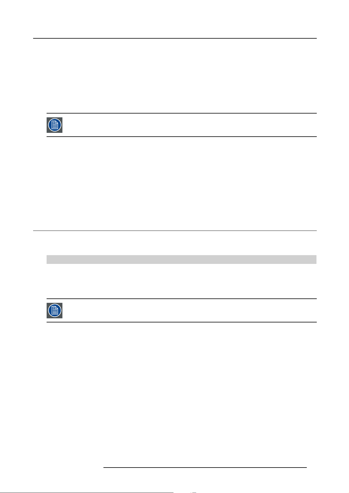
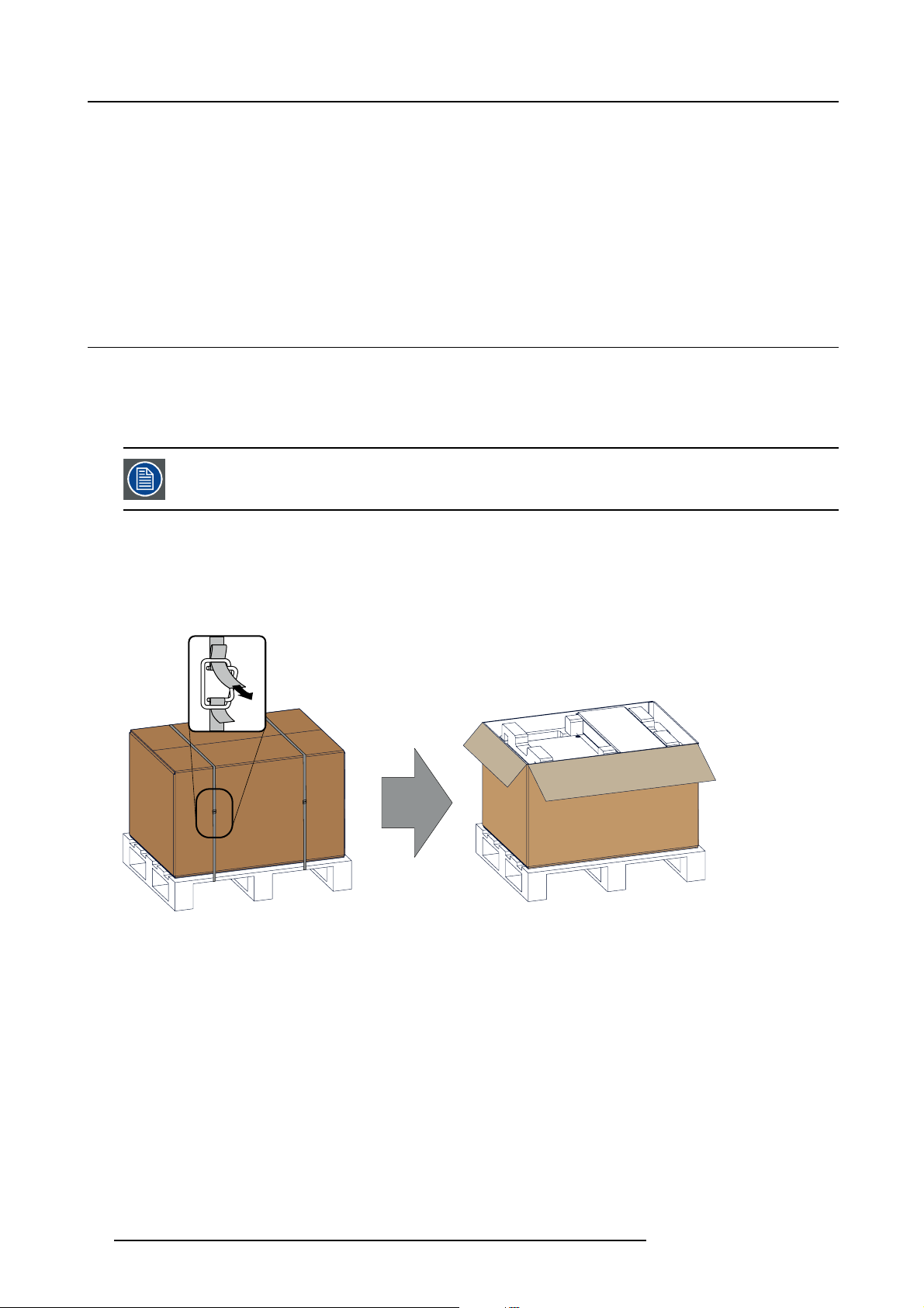
1. Remove the banding around the carton box, by releasing the fastening clips as illustrated, and open the box.
Image 2-1
Opening box
2. Remove the small box on top of the projector. This box contains the accessories such as manuals, remote control, etc.
14
R5906070 HDX 4K 09/04/2018
Page 19
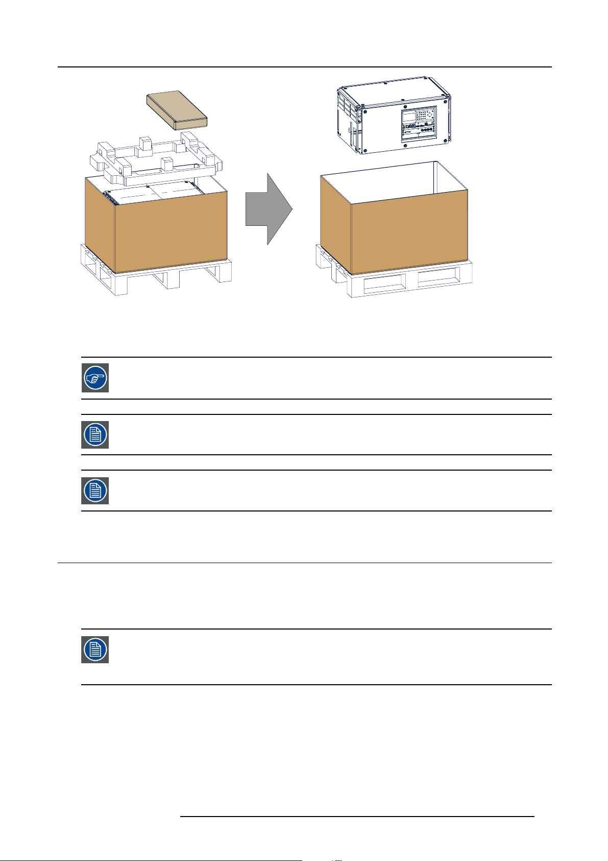
Image 2-2
Remove carton and foam rubber
3. Take out the foam rubber.
4. Take out the projector.
2. Installation preparations
Save the original shipping cardboard box and packing material. They will be necessary if you ever have to
ship your projector. For m aximu m protection, repack your projector as it was originally packed at the factory.
A rubber foam inside a plastic bag is placed into the lens opening of the projector. It’s recommended to reuse
this foam and plastic back each time you transport the projector. This to prevent intrusion of dust an d foreign
particles.
The lens is delivered in a separate box.
2.3 Initial inspection
General
Before shipment, the projector was inspected and found to be free of mechanical and electrical defects. As soon as the projector is
unpacked, inspect for any damage that may have occurred in transit. Save all packing material until the inspection is completed. If
damage is found, file claim with carrier immediately. The Barco Sales and Service office should be notified as soon as possible.
The packaging of the HDX is provided with a shock-watch label. If this shock-watch label was triggered (red
colored at arrival) during transport, that indicates that the package was p ossibly roughly handled by the transport company. In this case, the instructions mentioned on the label, should be followed, which are: adding
a note on the “bill of lading” and informing the transport company and the Barco sales and service office as
soon as p ossible.
Box content
After unpacking the projector it is recommended to check if all following items where included:
R5906070 HDX 4K 09/04/2018
15
Page 20
2. Installation preparations
• Three power cords of 2.5 meter, one CEE (7), one NEMA L6-20P and one CH2–16P
• One Quick Start guide
• One Safety manual
• One Web site reference sheet
• One remote control unit (RCU)
• 2 batteries for the RCU.
One xenon lamp is mounted inside the lamp house at delivery. The projector lenses are not included in the
package of the projector.
Mechanical check
This check should confirm that there are no broken knobs or connectors, that the cabinet and panel surfaces are free of dents and
scratches, and that the operating panel is not scratched or cracked. The Barco Sales and Service office should be notified as soon
as possible if this is not the case.
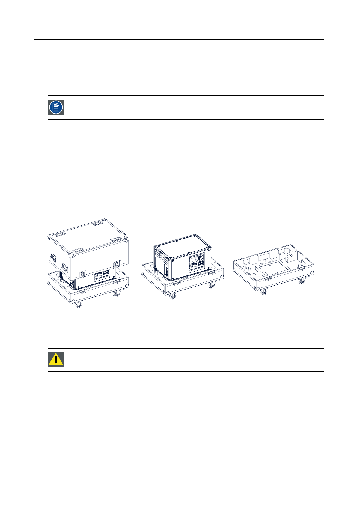
2.4 HDX flight case
Introduction of the HDX flight case
The HDX flight case is designed to transport the HDX in a safe and secure manner. The four caster wheels, provided with breaks,
and the four handles make the HDX flight case easy to handle. The floor of the flight case wagon is equipped with two small covered
compartments to store the remote control and the rigging clamps.
Image 2-3
HDX Flight case
Order number flight case: R9864090
The dimensions of the flight case are optimal for maximum utilization of the floor area of a truck. The cover of the HDX flight case
has 4 stacking dishes, which allows to stack the flight cases.
WARNING: M axim um stack two (2) HDX fl ight cases high. Never higher.
2.5 Projector configurations
The different configurations
Depending on the installation the projector can be mounted in different ways, the different configurations are:
1. Front / Table (F/T)
2. Front / Ceiling (F/C) (upside down)
3. Front / Ceiling (F/C) (table position)
4. Rear / Table (R/T)
5. Rear / Ceiling (R/C) (upside down)
6. Rear / Ceiling (R/C) (table position)
16 R5906070 HDX 4K 09/04/2018
Page 21
2. Installation preparations
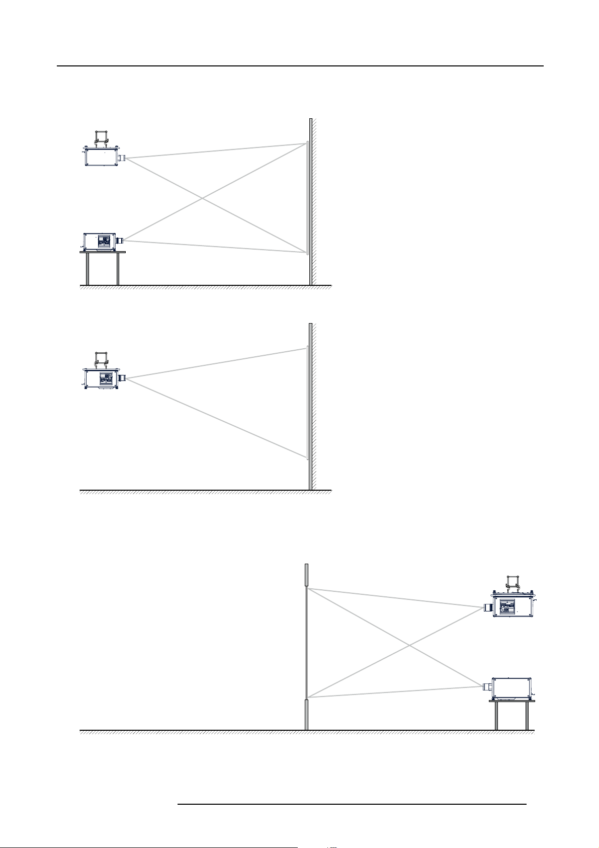
Front projection
The projector is installed, either in a table mount or ceiling mount configuration, at the same side of the screen as the audience.
AUDIENCE
F/C
F/T
Image 2-4
Front projection
AUDIENCE
F/C
Image 2-5
Front proje ction, Ce iling mounted, in table position
SCREEN
FLOOR
SCREEN
FLOOR
Rear projection
The projector is installed, either in a table mount or ceiling mount configuration, at the other side of the screen opposite the audience.
AUDIENCE BACKSTAGE
R/C
SCREEN
FLOOR
Image 2-6
Rear projection
R5906070 HDX 4K 09/04/2018 17
R/T
Page 22
2. Installation preparations
Image 2-7
Rear projection, ceiling mounted in table position
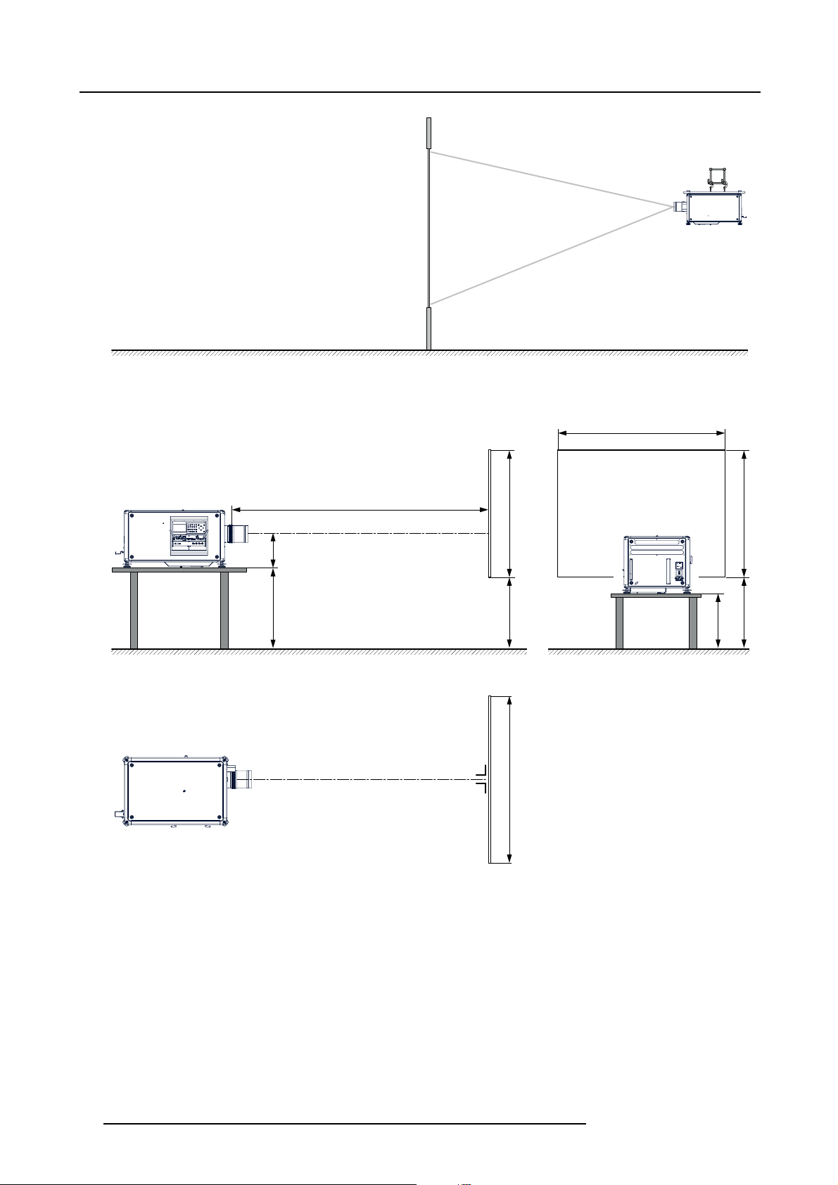
Positioning the projector
AUDIENCE BACKSTAGE
R/C
SCREEN
FLOOR
SW
PD
SCREENSCREEN
SHB
SHB
ACD
SCREEN
CD
FLOOR
SW
Image 2-8
Positioning p rojector
The projector should be installed at right angles (horizontally and vertically) to the screen at a distance PD. Note the distance (A)
between lens centre and table surface is slightly variable. This distance (A) is nominal 35 cm in case all feet are turned in completely
and the vertical lens shift is set to zero (0).
On axis / off axis projection
The position of the projector with reference to the screen may also be different depending on the installation. Basically the projector
can be positioned in On-Axis or Off-Axis confi guration. On-Axis configuration means that the projector is positioned so as to have
the centre of the lens coinciding with the centre of the screen. Off-Axis projection is obtained by shifting the lens up, down, left or
right. Several parameters can be calculated determining the position in any installation.
Formula to calculate the distance CD for On-Axis projection: CD=SH/2+B-A
18
R5906070 HDX 4K 09/04/2018
Page 23
2. Installation preparations
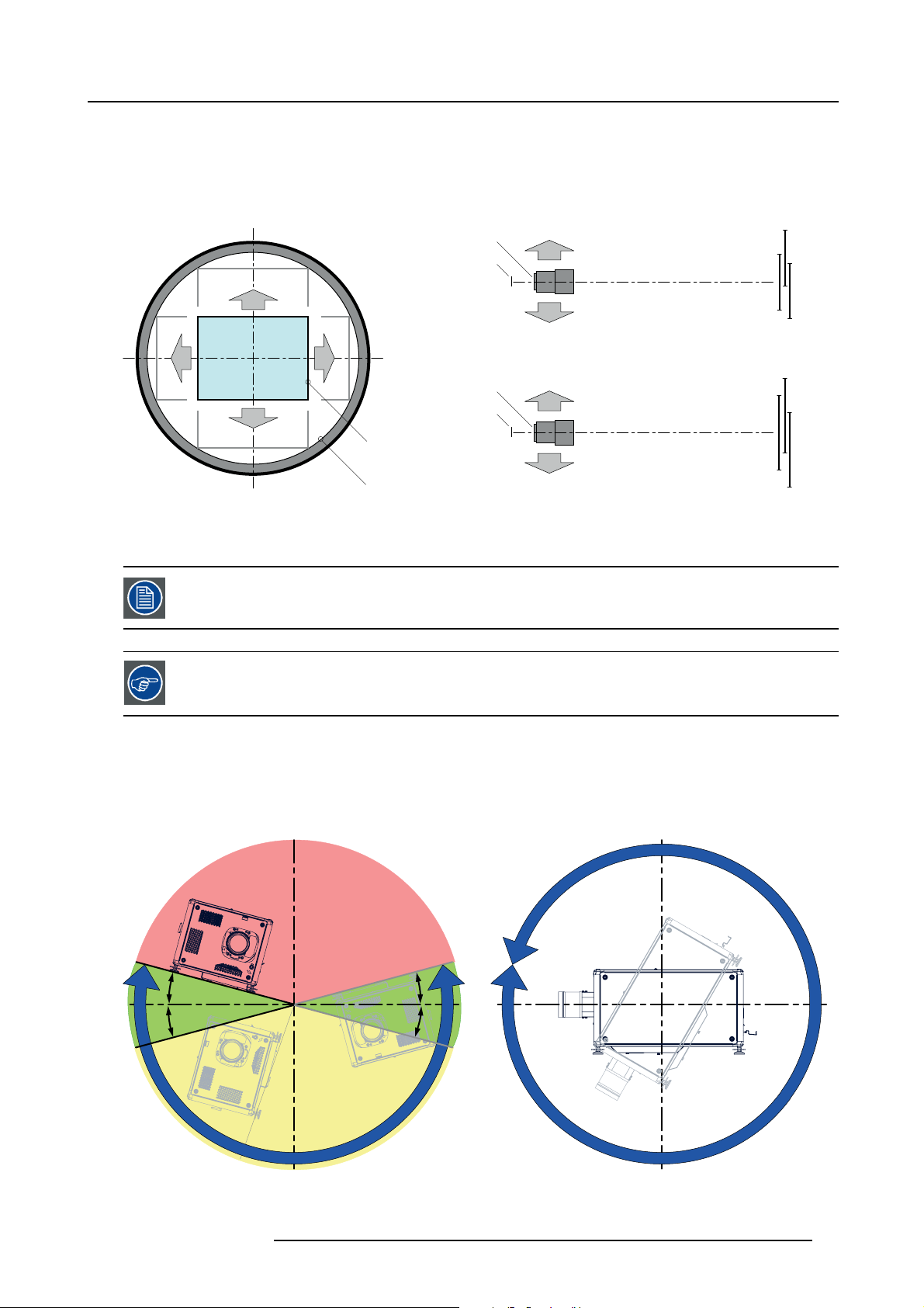
Shift range
The lens can be shifted with respect to the DMD (P) which result in a shifted image on the screen (Off-Axis). A 100% shift means that
the centre point of the projected image is shifted by half the screen size. In other words, the centre point of the projected image falls
together with the outline of the image in an On-Axis projection. Due to mechanical and optical limitations it’s recommended to keep
the shift values within the field of view (F) as illustrated below. Within these shift ranges the projector and lens perform excellently.
Configuring the projector outside these shift ranges will result in a slight decline of image quality.
U
-50% +50%
L R
D
Image 2-9
Vertical and horizontal shift range
PDMD.
F Field of view.
It is mechanical possible to shift outside the recommended field of view, but it will result in a decline of image
quality depending on the used lens and the zoom p osition of the used lens . Furthermore, shifting too much
in both directions will result in a blurred image corner.
Best image quality is projected in the On-Axis configuration.
+120%
-20%
F
P
F
P
P
F
U
D
L
R
SIDE VIEW
TOP VIEW
+120%
-20%
-50%
+50%
Horizontal and vertical projector tilt ranges
The projector can be rotated and mounted at any vertical angle. In other words, you can tilt the lens side of the projector as much
as desired for your application.
Side to side tilt, however, must not exceed ±15°. This limit ensures that the lamp in the projector operates properly and safely. More
tilting within area C is allowed but lamp flicker can happen.
B
MAX
15°
15°
A
A
15°
15°
MAX
360°
C
Image 2-10
A Tilting allowed without problems
B No tilting allowed in this area
R5906070 HDX 4K 09/04/2018 19
Page 24
2. Installation preparations
C Tilting allowed but lamp flicker possible
Projector lamp will not start up w hen out of tilt range due to build-in tilt sensor.
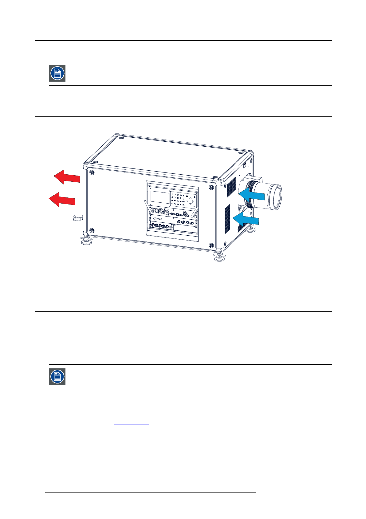
2.6 Projector air inlets and outlets
Air inlets and outlets
Image 2-11
The HDX has 3 air inlet channels and 3 air outlets. The air outlets are located at the rear of the projector. The air inlets are located
at the front of the projector.
2.7 Free download of Projector Toolset
About Projector Toolset
Projector Toolset is a software tool to set up, configure, manage and control Barco projectors.
The Projector Toolset software works with configurations that can be loaded. Several configurations can be controlled simultaneously. Even when the configurations are connected via different ways.
Projector Toolset is a standalone appli
Projector Toolset is only available in a download version, no CD can be ordered.
Where to find the download file(s)
The program and all necessary plug-ins, as well as the Reference manual can be downloaded for free from my.barco.com. Registration is necessary.
1. Go to the Barco website w
2. On the home page, click on myBarco log in.
3. On the Sign In page, enter your Email address and your password to login.
If you are not yet registered click on New to myBarco? and follow the instructions. With the created login and password, it is
possible to enter the Partner zone of Barco.
When your login is correct, the Partner zone is free accessible.
4. In the search field, enter Projector Toolset and click on the search icon.
5. Select Technical Downloads.
6. Click on Application Software and download the Projector Toolset software package, which includes the device plug-in updates.
cation that runs on a Java Virtual Machine and that does not require extra services to run.
ww.barco.com.
20
R5906070 HDX 4K 09/04/2018
Page 25

2. Installation preparations
When downloading the complete Projector Toolset, this software contains already the latest device plug-ins. When you already have
the latest core version of Projector Toolset, it is possible to download only device plug-in updates from the same web site location.
As Projector Toolset is a stand alone application, it is not necessary to install any other software. A Java virtual machine is included
with this download.
To download the reference manual, select Reference Guide and download the latest version of the manual for your projector.
Installation
Download first the reference manual and follow the installation instructions as written in this manual.
R5906070 HDX 4K 09/04/2018
21
Page 26

2. Installation preparations
22 R5906070 HDX 4K 09/04/2018
Page 27
3. Pulse Remote Control Unit
3. PULSE REMOTE CONTROL UNIT
3.1 Remote control, battery installation
Where to find the batteries for the remote control ?
The batteries are not placed in the remote control unit to avoid control operation in its package, r
time. At delivery the batteries can be found in a separated bag attached to the remote control unit. Before using your remote control,
install the batteries fi rst.
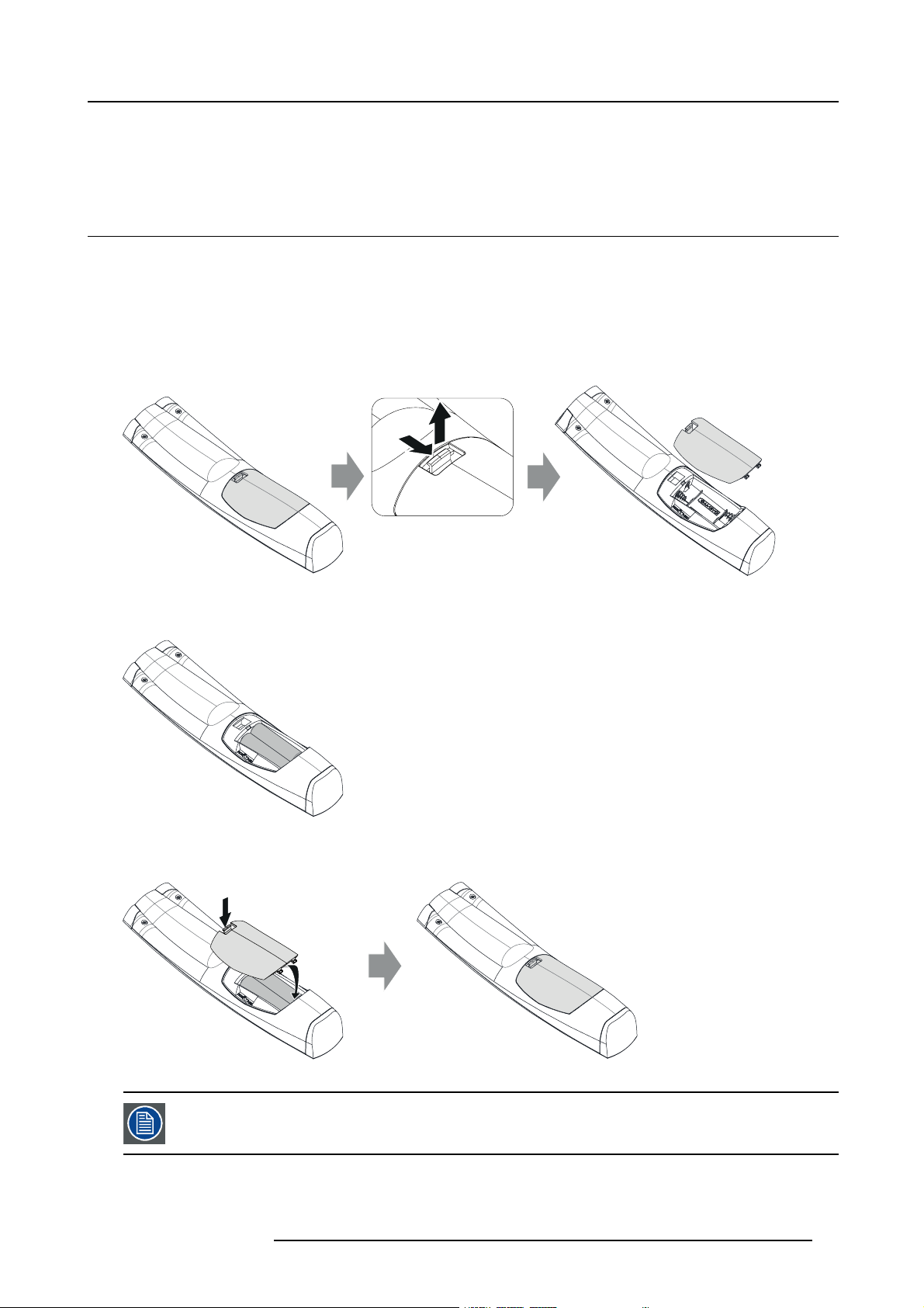
How to install
1. Push the battery cover tab with the fingernail a little backwards (1) and pull, at the same time, the cover upwards (2).
esulting in a shorter battery life
1
Image 3-1
2. Insert the two AA size batteries, making sure the polarities match the + and - marks inside the battery compartment.
Tip: Use alkaline batteries for optimum range and life time.
+
-
-
+
Image 3-2
3. Insert (1) both lower tabs of the battery cover in the gaps at the bottom of the remote control, and press (2) the cover until it clicks
in place.
2
2
+
-
Image 3-3
When replacing batteries, the broadcast address of the RCU will be reset to its default value ’0’.
R5906070 HDX 4K 09/04/2018 23
1
-
+
Page 28
3. Pulse Remote Control Unit
CAUTION: Replace w ith the correct battery type. Use two AA size batteries. There is a risk of explosion if the
battery is replaced with an incorrect type.
CAUTION: Replace the battery as explained ab ove. There is a risk of explosion if the battery is incorrectly
installed.
3.2 Remote control, protocol setup
About the used protocol
The protocol is the code send out by the remote control when a button is pressed. Depending on this code, the projector can decode
the signals. The remote control can be used with two different protocols, RC5 and NEC. Depending on the projector to control the
remote control can be switched between these protocols.
Which protocol to use
•TheNEC protocol has to be used for Barco projectors based on the Pulse platform: F70, F80, F90, HDX 4K, UDX, XDL, etc.
•TheRC5 protocol has to be used all other Barco projectors: HDX W, HDF W, HDX 2K, etc.
How to set
1. Remove the cover. For more info on how to remove, see "Remote control, battery installation", page 23.
2. Place the switch in the NEC position.
Image 3-4
Remark with RC5 protocol
Not all buttons of the Pulse RCU are one-to-one compatible with the legacy Barco RCU. Button pairs SHUTTER open/close and
POWER on/off emit the same code (per pair) when in RC5 mode, because the legacy RCU’s only had 1 button for Shutter and 1
button for Standby.
3.3 Remote control, on/off button
Purpose of the remote control on/off button
The Pulse remote control unit has at the front side an on/off switch (reference 1 image 3-5). Switching off the remote control prevents
that unwanted commands are send due to an accidental key press. Furthermore, switching the RCU off will extend the battery life
time of the remote control.
To activate the remote control press the on/off button.
To deactivate the remote control press the on/off button again.
Default when (re)placing batteries, is “ON”.
24
R5906070 HDX 4K 09/04/2018
Page 29
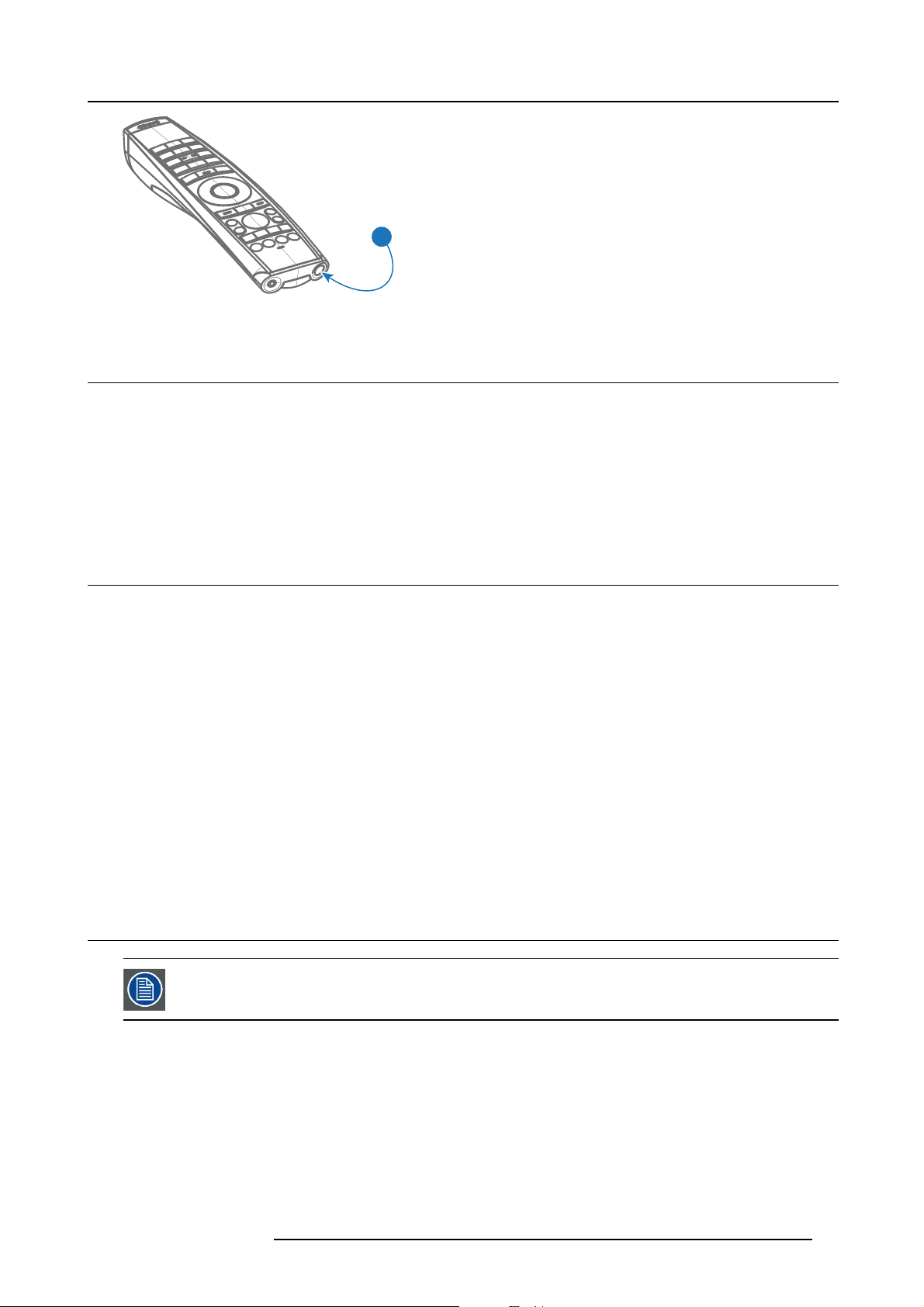
3. Pulse Remote Control Unit
1
Image 3-5
3.4 Functions of the “button pressed indicator”
Functions button pressed indicator
• Rapidly flashes when commands are sent, this is the normal “button pressed” indication.
• 1 Short flash when remote control is switched ON by means of the on/off button.
• Continuously lit (up to 5 seconds) when address digits are expected after pressing the ADDR button.
•Slowlyfl ashes (2 times a second) when the battery level is becoming low; typically when more than 85% of the useful life is
past.
3.5 Displaying a nd Programming addresses into the RCU
Displaying the Projector Address on the Screen.
1. If the projector is on, press the menu key and navigate to the Status page. The projector address and the broadcast address can
be seen under the Communication heading.
The projector’s address is displayed on the LCD status screen and / or the OSD.
How to P rogram an Address into the RCU?
1. Press the Address button until the Button pressed indicator lights up continuously (proximately 5 seconds).
2. Enter the address with the digit buttons within the time the indicator lights up (also proximately 5 seconds).
Note: That address can be any value between 0 and 31.
Tip: A few examples:
To enter address 3, press "3" digit button on the RCU to set the RCU’s address to 3 and wait until the button pressed
indicator is out. Alternatively, you can also press “0” and “3”. This way, the button pressed indicator goes out immediately.
To enter address 31, then press “3” and “1” on the digit button on the RCU and the button pressed indicator goes out
immediately.
3.6 Using the XLR connector of the RCU
Connecting a cable with the XLR connector will reset the broadcast address of the RCU to its default value ’0’.
How to use the XLR connector
1. Remove the XLR cover by pulling it backwards.
R5906070 HDX 4K 09/04/2018
25
Page 30
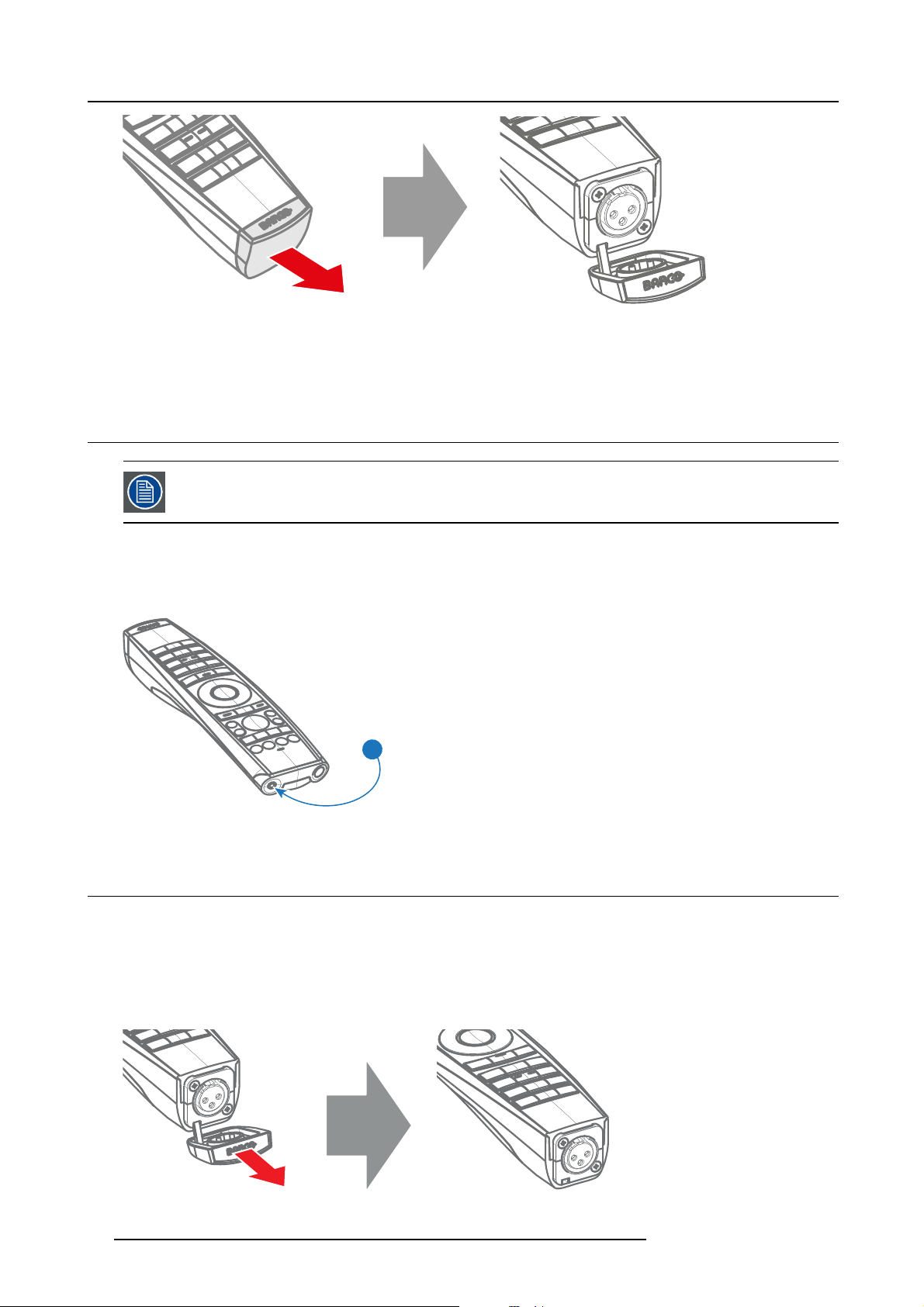
3. Pulse Remote Control Unit
Image 3-6
2. Connect a cable with XLR plug into the XLR connector of the RCU.
3. Connect the other end of the cable with the XLR input of the projector.
3.7 Using the mini-jack connector of the RCU
Connecting a cable with the mini-jack connector will reset the broad cast address of the RCU to its default
value ’0’.
How to use the mini-jack connector
1. Connect a cable with the mini-jack connector (reference 2 image 3-7) of the RCU.
2. Connect the other end of the cable with the mini-jack input of the projector.
2
Image 3-7
3.8 Silicone protection sleeve for the RCU (optional)
Introduction
Barcooffersasiliconeformfitting protection sleeve for the Pulse RCU. The silicone material keeps it comfortably, non slip and soft
touch. All buttons and holes remain accessible. The sleeve is quick and easy installed. For ordering information see Barco website.
How to install
1. Pull off the rubber XLR-lid from the RCU.
Image 3-8
26 R5906070 HDX 4K 09/04/2018
Page 31

3. Pulse Remote Control Unit
2. Place back side (XLR side) of the RCU into the sleeve and pull the other side of the sleeve over the front side of the RCU.
Image 3-9
R5906070 HDX 4K 09/04/2018 27
Page 32

3. Pulse Remote Control Unit
28 R5906070 HDX 4K 09/04/2018
Page 33

4. PHYSICAL INS TALLATION
Overview
• Connecting the projector with the power net
• Alignment of a table mounted projector
• Mounting the bottom carry handler
• Mounting the top carry handler
• Suspension of the projector with rigging clamps
• Alignment of a ceiling mounted projector
4.1 Connecting the projector with the power net
CAUTION: Use only the power cord provided with the projector.
How to connect with local power net
1. Ensure that the power switch stands in the ’0’ (OFF) position (1).
4. Physical Installation
1
2
3
Image 4-1
Power input
2. Connect the female side of the power cord with the power input socket of the projector (2).
3. Secure the power plug by locking the plug holder clamp (3).
4. Connect the male side of the power cord to the local power net.
Caution: Ensure that the power net meets the power requirements of the projector.
WARNING: Do not attempt operation if the AC supply and cord are not within the specified voltage and pow er
range.
R5906070 HDX 4K 09/04/2018 29
Page 34

4. Physical Installation
CAUTION: Once the projector is switched to standby, the lamp cooling fans will continue to run for approx-
imately five minutes to ensure that the projector and lamp have sufficiently cooled, at which point the fans
will automatically decrease to standby. To avoid thermal stress that can lead to premature lamp failure, never
unplug the power cord while the lamp cooling fans are running. Never unplug the power cord to power down
the projector, first switch off the power switch and then unplug the power cord.
Fuses
The projector is protected with an automatic circuit breaker of 20 A which is built into the power switch.
The voltage meter is protected with a fuse (1A) which is located on the neutral bonding cable. If necessary to replace this fuse,
consult a service technician.
4.2 Alignment of a table mounted projector
How to align
1. Place the projector in the desired location. Take into account the zoom range of the used lens and the size of the screen.
2. Project one of the internal hatch patterns on the screen.
3. Turn the adjustable feet in or out until the projected hatch pattern has a perfect rectangle shape and is leveled.
Image 4-2
Level alignment
When this is achieved, the projector is set horizontal and vertical at right angles to the screen.
SCREEN
Image 4-3
Angle adjustment
4.3 Mounting the bottom carry handler
Necessary tools
Open wrench 17 mm
Necessary parts
4x bolt M10 x 16 mm
How to mount
1. Turn the projector upside down.
2. Turn out the 4 feet.
SCREEN
30
R5906070 HDX 4K 09/04/2018
Page 35

Image 4-4
Remove feet
3. Turn out the feet of the carry handle as far as possible.
4. Physical Installation
Image 4-5
Mount carry handle
4. Place the carry handle on the projector as illustrated. Adjustment knob to the back of the projector.
Make sure that the mounting holes matches the holes in the projector.
5. Insert a bolt in each corner and turn in these bolts.
R5906070 HDX 4K 09/04/2018
31
Page 36

4. Physical Installation
2
1
Image 4-6
Insert bolts
4.4 Mounting the top carry handler
Purpose
This carry handle can be used to transport the projector in an easy way.
Necessary tools
8 mm Allen wrench
Necessary parts
• 4x bolt M10 x 16
• 4x washer
• 1x carry handler
How to mount
1. Place the carry handle on top of the projector so that the fixation holes match the holes in the projector.
1
1
Image 4-7
top carry handle
2. Turn in the 4 fixation bolts (1)
32 R5906070 HDX 4K 09/04/2018
. Insert a washer between the bolt and the carry handle.
Page 37

4. Physical Installation
4.5 Suspension of the projecto r with rigging clamps
Rigging points and rigging clamps
When a carrying handle is mounted at the bottom side of the projector, eight slots are available to mount rigging clamps. Four slots
are longitudinally (1) oriented and four slots are transversely (2) oriented. Each slot contains a rigging point of which the position in
the slot can be adjusted depending on the size of the truss installation. The rigging clamps can be attached to those rigging points,
which allows an easy and fast physical setup of the projector in a hanging configuration.
1
2
Image 4-8
Rigging points
Necessary tools
• Open end spanner 24 mm
• Open end spanner 17 mm
Necessary parts
4 rigging clamps
How to ins tall and use the rigging clamps
1. Measure the distance, center tube as reference, between the two used support bars of the truss.
X mm
Image 4-9
Truss, example
2. Turn the projector upside down and slide the rigging points on there place in the slots, according the measured distance and
secure this position. To release the nuts of the rigging points use a 24 mm open ended spanner. Ensure that the rigging points
are symmetrically lined up, so that the projector will hang in balance.
Warning: Be careful while working with heavy loads.
Warning: Always s ecure the rigging points after adjustment.
X mm
Image 4-10
Rigging points, distance
R5906070 HDX 4K 09/04/2018 33
Page 38

4. Physical Installation
3. Turn in the rigging clamps into the rigging points using a 17 mm open ended spanner and secure the rigging clamps by turning
the safety nut on the rigging clamp against the rigging point using a 17 mm open ended spanner.
Image 4-11
Mount rigging clamps
Warning: Always use four (4) rigging points, equally spread, to suspend the projector.
4. Place all four rigging clamps in open position.
5. Place the projector (upside down) under the truss installation and lower the truss until the support bars of the truss are nearby
the rigging clamps mounted on the projector.
Image 4-12
Mount to truss
6. Lift up the projector and hook the four rigging clamps over the support bars of the truss.
34
R5906070 HDX 4K 09/04/2018
Page 39

4. Physical Installation
7. Lock all four rigging clamps by turning the fixation handle clockwise.
Image 4-13
Clamp fixation
8. Install the 2 safety cables, one on both sides of the carrying handle, and around the truss.
Mount the 2 safety cables around the carry handle (push the hook through the loop and then aroun
to much play (maximum 20 cm). If necessary turn the cable a few times around the truss before clasping the safety hook around
the cable.
d the truss so that there is not
Image 4-14
Security cables
9. Lift up the truss with the attached projector to the desired height.
Mount the 2 safety cables in such a way that when something goes wrong, the projector cannot fall more than
20 cm. If necessary, turn the cables a few times around the truss to obtain this maximum distance.
4.6 Alignment of a ceiling mounted projector
Necessary tools
17 mm open spanner
Skew adjustment
1. Turn the adjustment knob on the carry handle until the projected hatch pattern is perfectly squared.
R5906070 HDX 4K 09/04/2018
35
Page 40

4. Physical Installation
Skew
Image 4-15
Skew adjustment
Tilt adjustment with the clamps
1. Adjust both front side clamp or both back side clamps to adjust the tilting.
Always adjust by two to avoid deformation of the frame.
2. Loosen the security nut on both clamps.
3. Adjust the adjustment nuts of both clamps until the desired tilting is reached.
4. Turn the safety nut on the rigging clamp against the rigging point
36 R5906070 HDX 4K 09/04/2018
Page 41

5. Lenses & Lens selection
5. LENSES & LENS SELECTION
Overview
• Available lenses
• Lens selection
• Lens installation
• Lens removal
• Lens safety cable
• Scheimpflug adjustment
5.1 Available lenses
WARNING: Only use TLD+ ZOOM lenses. Using other lenses can touch and damage the mechanics of the
build-in Act uator! This can result in loud rattling noises and a damaged Actuator.
Limited amount of available lenses
In comparison to the regular HDX, the HDX 4k projectors have an actuator built in them to help provide a clear 4k image. This extra
device means that less space is available in the projector for lenses, thus causing a more restricted amount of lenses that can be
used. Using lenses other than the lenses mentioned in this chapter may damag
noises in the process and possibly a distorted image.
Due to the similar look to the “regular” 2k HDX projector, an extra warning label has been added on the lens holder to raise awareness
of this limit.
e the mechanics of the actuator, causing loud rattling
Image 5-1
Warning label
Available lenses for the HDX projector
Only the following TLD+ ZOOM Lenses can be used on the HDX projector. Do not use other types of lenses.
Image 5-2
R9801414: T LD+ zoom lens (0.8 - 1.16 : 1 )
R5906070 HDX 4K 09/04/2018 37
Image 5-3
R9862005: TLD+ zoom lens (1.16 - 1.49 : 1)
Image 5-4
R9862010: TLD+ zoom lens (1.5 - 2.0 : 1)
Page 42

5. Lenses & Lens selection
Image 5-5
R9862020: TLD+ zoom lens (2.0 - 2.8 : 1)
Image 5-8
R9829997: T LD+ zoom lens (7.5 - 11.0 : 1)
Image 5-6
R9862030: TLD+ zoom lens (2.8 - 4.5 : 1)
5.2 Lens selection
How to select the right lens
1. Determine the required screen width (SW).
2. Determine the approximate position of the projector in the room.
3. Start up the Lens Calculator on the Barco website: h
configuration.
The Lens Calculator window opens.
Image 5-7
R9862040: TLD+ zoom lens (4.5 - 7.5 : 1)
ttps://lenscalculator.barco.com/ to determine the possible lenses for your
38
R5906070 HDX 4K 09/04/2018
Page 43

Image 5-9
Lens calculator
5. Lenses & Lens selection
The Lens Ca lculator can also be used to determ ine the position of the projector when the lens type and screen
width is known.
Due to len s tolerances the results of calculated values may be different from meas ured values. These difference may vary +/- 5%.
5.3 Lens installation
WARNING: Only use TLD+ ZOOM lenses. Using other lenses can touch and damage the mechanics of the
build-in Act uator! This can result in loud rattling noises and a damaged Actuator.
How to install
1. Remove the foam rubber in the opening of the lens holder if not removed yet.
2. Do not remove the warning sticker from the lens holder.
3. Take the lens assembly out of its packing material and remove the lens caps on both sides.
4. Place the lens holder in the “unlocked” position by moving the lens lock handle (A) towards the lens power supply socket (B) as
illustrated.
R5906070 HDX 4K 09/04/2018
39
Page 44

5. Lenses & Lens selection
B
A
Image 5-10
Lens installation, preparation
5. Ensure that the lens holder stands in the On-Axis position (horizontal and vertical mid position).
Note: The lens holder is placed default in the O n-Axis po sition at factory.
6. Gently insert the lens in such a way that the lens connector matches the socket (B).
Image 5-11
Lens insertion
7. Insert the lens until the connector seats into the socket.
Warning: Do not release the Lens yet, as the L ens may fall out of the Lens Holder.
8. Secure the lens in the lens holder by sliding the lens lock handle into the “locked” position, which is away from the lens power
supply socket. Ensure the lens touches the front plate of the lens holder.
Image 5-12
Lock lens
9. Check if the lens is really secured by trying to pull the lens out of the lens holder.
40 R5906070 HDX 4K 09/04/2018
Page 45

5. Lenses & Lens selection
5.4 Lens removal
How to remove
1. Support the lens with one hand while you unlock the lens holder by sliding the lock handle towards the “unlocked” position as
illustrated.
Image 5-13
Lens removal, unlock
2. Gently pull the lens out of the lens holder.
Image 5-14
Lens removal
It’s recommended to place the Lens caps of the original Lens packaging, back on both sides o f the removed
Lens to protect the optics of the Lens.
It’s recommended to place the foam rubber of the original projector packaging, back into the Lens opening to
prevent intrusion of dust. Note that this foam rubber is packed in a plastic bag to prevent the dust, emitted by
the foam , from en te r ing the projector.
5.5 Lens safety cable
When using the safety ca ble ?
The lens safety cable must b
above persons.
Configuration differences
Therearetwodifferentconfigurations for the safety cable. The configuration used depends on the used carrying handle or hoisting
eye.
e used in any circumstances to protect a mounted lens in the lens holder when the projector is mounted
R5906070 HDX 4K 09/04/2018
41
Page 46

5. Lenses & Lens selection
•Configuration A applies when connecting the projector to the bottom carrying handle.
•Configuration B applies when connecting the projector to the top carrying handle.
Necessary parts
• Safety Cable (750 mm, Ø3 mm)
• Cable clamp M4
• Shackle 7x70 mm
• 4 x Cable clip (16x16 mm, Ø4 mm)
How to mount the cable
1. Paste four cable clips on the lens as illustrated (reference 1). Orient the open side of the clips towards the front of the lens.
2
2
1
1
Image 5-15
2. Snap the first loop end of the safety cable into one of the following clips and let the loop end point downwards.
a) Configuration A: Use the upper clip on the side of the cable bundle (reference 2, image 5-15).
b) Configuration B: Use the upper clip on the non-wired side (reference 2, image 5-16).
3. Slide the rest of the cable around the lens counterclockwise. Click the cable into every clip it passes in this loop.
Note: Make sure the cable passes between the lens and the c able bundle.
4. Slide the cable through the loop end at the beginning of the cable.
Image 5-16
Image 5-17
Example of configuration A
5. Install a U-bolt on the lens holder, with the open ends oriented outwards (reference 3). Make sure that both a part of the loop end
and the outgoing part of the safety cable are placed in the enclosure.
42
R5906070 HDX 4K 09/04/2018
Page 47

5. Lenses & Lens selection
3
3
Image 5-18
Example of Configuration A
Image 5-19
Example of Configuration B
6. Close the U-bolt and tighten it.
Note: Make sure the safety cable is tightened around the lens before tightening the U-bolt nuts.
7. Place the shackle through the free loop end of the safety cable.
How to mount the cable
1. Place the lens in the lens holder, using the lens locking mechanism.
Caution: Always make sure the lens is really secured by trying to pull the lens out of the lens holder.
2. Lead the cable end with the shackle around one of the following carrying handles:
-Configuration A: Around the bottom carrying handle.
-Configuration B: Around the top carrying handle.
3. Snap the shackle to the straight part of the cable.
4. Secure the shackle by screwing the safety ring of the shackle over the open end.
Image 5-20
R5906070 HDX 4K 09/04/2018 43
Page 48

5. Lenses & Lens selection
Image 5-21
Example using the top carrying handle
5.6 Scheimpflug adjustment
What has to be done ?
The lens holder has to be adjusted so that the “sharp focus plane” of the projected image falls together with the plane of the screen
(Fp1→Fp2). This is achieved by changing the distance between the DMD plane and the lens plane (Lp1→Lp2). The closer the lens
plane comes to the DMD plane the further the sharp focus plane will be. It can sometimes happen that you won’t be able to get a
complete focused image on the screen due to a tilt (or swing) of the lens plane with respect to the DMD plane. This is also known
as Scheimpflug’s law. To solve this the lens plane must be placed parallel with the DMD plane. This can be achieved by turning the
lens holder to remove the tilt (or swing) between lens plane and DMD plane (Lp3→Lp4).
Lp1
Lp2
DMD
Image 5-22
Scheimpflug principle
Scheimpflug principle
The "plane of sharp focus" can be changed so that any plane can be brought into sharp focus. When the DMD plane
and lens plane are parallel, the plane of sharp focus will also be parallel to these two planes. If, however, the lens
plane is tilted with respect to the DMD plane, the plane of sharp focus will also be tilted according to geometrical and
optical properties. The DMD plane, the principal lens plane and the sharp focus plane will intersect in a line below the
projector for downward lens tilt.
SCREEN
Fp1
Fp2
DMD
Lp3
Lp4
(Scheimpflug)
Fp4
Fp3
SCREEN
44 R5906070 HDX 4K 09/04/2018
Page 49

Scheimpflug adjustment points
A
a
B
5. Lenses & Lens selection
b
1
4
D
Image 5-23
Scheimpflug adjustments
Indication on drawing Function
4 Locking nut
1, 2 and 3 Scheimpflug adjustment nuts
A, B, C and D Set screws
a, b, c and d lock nuts
1, 2 and 3 are adjustment points.
4 is a locking point and NOT used during Scheimpflug adjustment.
C
d
2
3
c
CAUTION: In the HDX 4K, the Scheimpfl ug mechanism is positioned close to the actuator, which helps pro-
vide the 4k UHD images. To a void damaging the actuator during Scheimpflug adjustment, it is important to
have the projector be in 4k UHD mode during the adjustment. This because the actuator will vibrate w hile in
4k UHD mode.
If one of the Scheimphlug nuts would touch the vibrating actuator during adjustment, you will hear a loud
rattling noise. If heard, im med iately turn the nut counterclockwise until you can no longer hear the noise.
Remember and mark this position, as this wi
achieve without damaging the actuator.
Necessary tools
• Allenkey3mm
• Nut driver 13 mm
• Nut driver 10 mm
How to adjust
1. Project a green focus pattern in 4K UHD.
ll be the i nnerm ost position this Scheimpflug nut will be able to
R5906070 HDX 4K 09/04/2018
45
Page 50

5. Lenses & Lens selection
Image 5-24
2. Loosen the lock nuts (a, b, c and d). See image 5-23.
3. Loosen the 4 set screws (A, B, C and D) by 1 cm. See image 5-23.
4. Fully loosen lock nut 4. See image 5-23.
5. Optimize the focus of the projected image as follows:
a) Place the zoom lens in TELE position (smallest projected image) an
focus control.
b) Place the zoom lens in WIDE position (largest projected image) and adjust the focus by turning equally on nut 1, 2 and 3.
c) Repeat steps “a” and “b” until the projected image is as sharp as possible.
d adjust the focus using the lens focus barrel or motorized
1
Image 5-25
Center focusing
6. Sharpen bottom left corner of the screen by adjusting nut 1.
F
2
3
46
R5906070 HDX 4K 09/04/2018
Page 51

1
Image 5-26
Left bottom focusing
7. Sharpen bottom right corner of the screen by adjusting nut 2.
5. Lenses & Lens selection
F
Image 5-27
Right bottom focusing
8. Sharpen top right corner of the screen by adjusting nut 3
F
2
R5906070 HDX 4K 09/04/2018
47
Page 52

5. Lenses & Lens selection
3
Image 5-28
Corner focusing
9. Repeat from step 6 until the projected focus pattern is as sharp as possible in the center, left, right, top and bottom of the screen.
F
How to fixtheScheimpflug
Start the fixation as follows (steps must be followed strictly) :
1. Turn in set screw A, B and C. Tighten lightly (by hand).
Tip: Any movement of the im age will affect the S cheimp flug adjustme
2. Fasten lock nuts a, b and c.
3. Turn in set screw D lightly (by hand) allowing the image to move slightly (1/3 to 1/2 of a square).
nt
1/3 to 1/2
Image 5-29
4. Fasten lock nut d.
5. Tighten nut 4 until the offset of t
Tip: The amount of image move ment in s tep 3 w ill determine how tight the nut in s tep 5 w ill need to be turned to return the
image to its original position.
he image movement created in step 3 is canceled.
48
R5906070 HDX 4K 09/04/2018
Page 53

6. Input & Communication
6. INPUT & COMMUNICATION
Overview
• Introduction
• Removal of an input board
• Installation of an input board or a communication board
• Input source connections – Quad combo input Mark II
• Input source connections – Quad combo input Mk I
• Input source connections – Quad DP 1.2 Input board
• Communication connections
• LED and Button indication chart
6.1 Introduction
General
The Input & Communication side of the projector consists of a local keypad (1), a communication panel (4) and a Quad Combo input
board (5). The free input slot can be used for optional modules (e.g. the Quad DP 1.2 input board).
1
2 3
4
5
6
Image 6-1
1 Local Keypad and LCD panel
2 Optional antenna for WiFi connection
3 Optional antenna for GSM
4 Communication Panel
5 Quad Combo Input board
6 Free input slot (here filled with the Quad DP 1.2 Input board)
6.2 Removal of an inpu t board
WARNING: The procedures below may only be performed by Barco trained and qualified technicians.
CAUTION: Alwa ys w ear a wrist band which is connected to the ground while handling the electrostatic dis-
charge (ESD) sens itive parts.
R5906070 HDX 4K 09/04/2018 49
Page 54

6. Input & Communication
The procedure below is applicable to all the input modules of the Input & Communication Unit of the projector.
How to remove
1. Switch off the projector and unplug the power cord at the projector back side.
2. Release the 3 captive screws of the input module (4).
4
4
4
Image 6-2
3. Pull out the input module of the Input & Communication using the handles.
Image 6-3
CAUTION: Ensure that unused input slots of the Input & Communication Unit are always covered with a
dummy front plate. After removing one of the input modules, im me diately replace with an other one or install
a dummy front plate on the unused input slot.
50 R5906070 HDX 4K 09/04/2018
Page 55

6. Input & Communication
6.3 Installation of an input board or a communication board
WARNING: The procedures below may only be performed by Barco trained and qualified technicians.
CAUTION: Alwa ys w ear a wrist band which is connected to the ground while handling the electrostatic dis-
charge (ESD) sens itive parts.
Necessary tools
Phillips screwdriver PH1
The procedure below is applicable to all the input modules of the Input & Communication Unit of the projector.
How to install
1. Switch off the projector and unplug the power cord at the projector back side.
2. Push the input module in the Input & Communication Unit using the handles. Make sure the module seats in its sliders (2).
Pull in the module until the contacts (3) are fully inserted into the connectors.
2
Image 6-4
3. Tighten the captive screws of the input module.
R5906070 HDX 4K 09/04/2018
3
2
51
Page 56

6. Input & Communication
4
4
4
Image 6-5
4. Plug in the power cord at the projector back side.
5. IMPORTANT LAST STEP — Update the firmware of the installed module. Use the complete software package to install the
firmware via Projector Toolset or USB stick.
Tip: When a complete new software image is placed on the projector, all programmable components will be updated with the
latest version.
6.4 Input source connections – Quad combo input Mark II
About the Quad combo input Mark II
Due to demand from the market, Barco has created a second generation of the Input board to support 12G input and throughput on
the SDI connectors. From the release of this board onward, the Quad combo input will be supported and will be the standard input
board in every Input & Communication Unit,
The updates on this new board include the following compared to its predecessor:
• SDI Input A now also supports 12G input signals.
• SDI Input C now also functions as a loop-through output for any signal placed on Input A.
• SDI Input D now also functions as a loop-through output for any signal placed on Input B.
• HDBaseT Input 1 now also supports network connectivity.
SDI Input & output – How does it work?
When connecting an SDI source to the projector and the signal is HD or 3G, you can choose any of the four input connectors.
When connecting multiple projectors with the same signal, you can connect the signal as follows:
• Connect the source signal to Input A or B of the first projector.
• If the source signal is connected to Input A, connect Input/Output C to the Input of the following projector.
• If the source signal is connected to Inpu
• Continue in the same fashion until all projectors are connected.
When connecting a 12G SDI source to the projector, you can only connect that source to input A.
Only Input A accepts 12G SDI signals . Whil
B and connect that source to another projector in line (using Input/Output D), this fi rst projector itself w ill not
be able to process the 12G signal.
effectively replacing the Mark I variant.
tB, connect Input/Output D to the Input of the following projector.
e it is technically possible to connect a 12G SDI source to Input
52 R5906070 HDX 4K 09/04/2018
Page 57

6. Input & Communication
HD, 3G & 12G
HD & 3G
A
B
IN 0 OUT 0
IN 1
N.C.
IN 0 OUT 0
N.C.
IN 1
OUT 1
OUT 1
FPGA
IN: HD & 3G
OUT: HD, 3G & 12G
IN: HD & 3G
OUT: HD & 3G
Image 6-6
C
D
N.C.
N.C.
SDI IN/OUT
SDI OUT
SDI IN/OUT
SDI OUT
OUT 0
IN 0
OUT 0
IN 0
Spotting the difference between the Mark I and M ark II Input boards
Since there will be projectors in the field that have the Mark I Input Board and others that have the Mark II input board, it is important
to know the difference between the two variants.
While there are several minor and barely noticeable differences between the two boards, there is one real visual aid to tell the two
variants apart. There are visual markings added on the Mark II Input board, marking which connector supports 12G and which only
supports 3G.
SDI IN SDI IN/OUT
SEL
1
Image 6-7
Mark 1 Quad Combo input board, without markings above the SDI inputs
2
Image 6-8
Mark 2 Quad Combo input board, with 3G/12G markings above the SDI inputs/outputs.
SYNC
A
SDI IN SDI IN/OUT
3G/12G
SEL
SYNC SYNC SYNC SYNC
AB
SEL
SYNC
B
3G
SEL
SEL
SYNC
C
3G
SEL
CD
SEL
SYNC
D
3G
SEL
Overview Mark 2 Quad Combo Input board
SDI IN SDI IN/OUT
3G/12G
SEL
3G
SYNC SYNC SYNC SYNC
ABCD
1 2 3 4 5 6 7 8
Image 6-9
1 Quad SDI channel A: 3G/12G input
2 Quad SDI channel B: 3G input
3 Quad SDI channel C: 3G SDI input + 3G/12G output
4 Quad SDI channel D: 3G SDI input / output
5 DisplayPort Input
6 HDMI input
7 HDBaseT input 1
8 HDBaseT input 2
3G
SEL
3G
SEL
SEL
SEL
DP HDBT 2
SYNC SYNC
SEL
HDMI HDBT 1
SEL
SYNC
SEL
SYNC
R5906070 HDX 4K 09/04/2018 53
Page 58

6. Input & Communication
The yellow LED lights up when valid input sync is detected.
The green LED lights up when the input is selected .
The green LED lights blink when the input/output is selected and configured as output.
Input specifications – SDI Inputs
HD-SDI follows the SMPTE 292M standard
3G SDI follows the SM PTE 425M standard Level A
12G-SDI follows the SMPTE ST-2082-1 and ST -2082-10 st andards.
Color space YCbCr
Color depth
Chroma s ampling 4:2:2
Audio support not supported
For future release
Video timings
progressive
10 bpc
• 3D support
• Interlaced support
• Segmented frame support
Type Port type Format
HD-SDI Single link
Quad link
3G-SDI “BarcoLink” Single link
Quad link
12G-SDI (Channel A
only)
Single link 3840 x 2160 @50 Hz and @60 Hz
• Up to 1920 x 1080 @24 Hz
• Up to 1920 x 1080 @25 Hz
• Up to 1920 x 1080 @30 Hz
• Up to 1280 x 720 @50 Hz
• Up to 1280 x 720 @60 Hz
1920 x 1200 @50 Hz, @59.94 Hz and @60 Hz.
4096 x 2160 @50 Hz and @60 Hz
Input specifications – HD MI Input
Pixel rate 25 – 600 MHz pixel clock
HDCP support
Color space
Color depth
3D support
For future release
• HDCP 1.x
• HDCP 2.2
• RGB 4:4:4
• YCbCr 4:2:0
• YCbCr 4:2:2
• YCbCr 4:4:4
• RGB 4:4:4
• 24 bpp
• 30 bpp
• 36 bpp
• Field sequential 3D (Active 3D)
• Passive 3D not supported on this board.
• Interlaced support
54 R5906070 HDX 4K 09/04/2018
Page 59

Audio Not supported
Video timings
• Up to 4096 x 2160 @24 Hz
• Up to 4096 x 2160 @25 Hz
• Up to 4096 x 2160 @30 Hz
• Up to 2048 x 1080 @48 Hz
• Up to 4096 x 2160 @50 Hz
• Up to 4096 x 2160 @60 Hz
CAUTION: The HDBaseT inputs can bridge a distance of 100 m but are sensitive to radiated electromagnetic
interference: radiated electromagnetic in terference (e.g. from GSM or switching inductive or capacitive loads)
within the limits of electromagnetic compatibility requirements of 3 V/m can cause random
rary loss of the projected image.
As such, shielded CAT-6 cables with metal RJ-45 connectors are recommended; ch oose cable length no longer
than required and route HDBT cable optimally screened from possible sources of electromagnetic emission.
Input specifications–HDBaseTinputs
Pixel rate 25 – 297 MHz pixel clock
Color space
Color depth
HDCP support HDCP 1.x supported on HDBaseT Input 1
Network support Yes, on HDBaseT Input 1
For future release
Audio not supported
Video timings
progressive
• YCbCr 4:2:2
• YCbCr 4:4:4
• RGB 4:4:4
• 24 bpp
• 30 bpp
• 36 bpp
• 3D support
• Interlaced support
Layout m ode
Standard layout (1x1
layout)
2 Column mode (2x1
layout)
Supported formats
• Up to 4096 x 2160 @24 Hz
• Up to 4096 x 2160 @25 Hz
• Up to 4096 x 2160 @30 Hz
• Up to 2048 x 1080 @48 Hz
• Up to 2560 x 1600 @50 Hz
• Up to 2560 x 1600 @60 Hz
• 1920 x 2160 @50 Hz
• 1920 x 2160 @60 Hz
• 2048 x 2160 @50 Hz
• 2048 x 2400 @60 Hz
6. Input & Communication
flashes or tempo -
CAUTION: In order to display high resolution images (e.g.: 3840 x 2160 @60 Hz) via the DP1.2 input, the
quality of the cable must be adequate, in addition the length of the cable can also influence the performance.
In case there is an issue with one of these criteria the autom atic link-training initiated by the DP-standard may
decide to switch to a lower resolution.
Input specifications – DisplayPort 1.2 input
Pixel rate Up to 600 MHz pixel clock
Color space
R5906070 HDX 4K 09/04/2018 55
• YCbCr 4:2:2
• YCbCr 4:4:4
• RGB 4:4:4
Page 60

6. Input & Communication
Color depth
• 24 bpp
• 30 bpp
• 36 bpp
Data rate support
• 1.62 Gbps: Reduced Bit Rate (RBR)
• 2.7 Gbps: High Bit Rate (HBR)
• 5.4 Gbps: High Bit Rate 2 (HBR2)
HDCP support HDCP 1.4
For future release
• Interlaced support
Audio not supported
3D support
• Field sequential 3D (Active 3D)
• Passive 3D not supported on this board.
Video timings
progressive
2D / 3D Layout M ode Supported formats
2D Standard layout (1x1 layout)
Active 3D
• Up to 4096 x 2160 @24 Hz
• Up to 4096 x 2160 @30 Hz
• Up to 2048 x 1080 @48 Hz
• Up to 4096 x 2160 @50 Hz
• Up to 4096 x 2160 @60 Hz
• Up to 2560 x 1600 @120 Hz
Standard layout (1x1 layout)
• 1600 x 1200 @120 Hz
• 2560 x 1080 @120 Hz
• 2560 x 1600 @120 Hz
6.5 Input source connections – Quad combo input Mk I
Overview Mark 1 Quad Combo Input board
SDI IN SDI IN/OUT
SEL
SYNC
A
SEL
SYNC
B
SEL
SYNC
C
SEL
SYNC
D
1 2 3 4 5 6 7 8
Image 6-10
1 Quad SDI channel A: 3G input
2 Quad SDI channel B: 3G input
3 Quad SDI channel C: 3G SDI input / output
4 Quad SDI channel D: 3G SDI input / output
5 DisplayPort Input
6 HDMI input
7 HDBaseT input 1
8 HDBaseT input 2
The yellow LED lights up when valid input sync is detected.
The green LED lights up when the input is selected.
Input specifications – SDI Inputs
3G SDI follows the SM PTE 425M standard Level A
HD-SDI follows the SMPTE 292M stand
ard
SEL
DP
SYNC SYNC
HDM I
SEL
HDBT 1
SEL
SYNC
HDBT 2
SEL
SYNC
Color space YCbCr
Color depth
10 bpc
Chroma s ampling 4:2:2
56 R5906070 HDX 4K 09/04/2018
Page 61

6. Input & Communication
Not supported
Video timings
progressive
• Audio support
• 3D support
• Interlaced support
• Segmented frame support
Type Port type Format
HD-SDI Single link
3G-SDI Level A Single link
3G-SDI “BarcoLink” Single link
Input specifications – HD MI Input
Pixel rate 25 – 600 MHz pixel clock
HDCP support
Color space
Color depth
3D support
For future release
Audio not supported
Video timings
• HDCP 1.x
• HDCP 2.2
• RGB 4:4:4
• YCbCr 4:2:0
• YCbCr 4:2:2
• YCbCr 4:4:4
• RGB 4:4:4
• 24 bpp
• 30 bpp
• 36 bpp
• Field sequential 3D (Active 3D)
• Passive 3D not supported on this board.
• Interlaced support
• Up to 4096 x 2160 @24 Hz
• Up to 4096 x 2160 @25 Hz
• Up to 4096 x 2160 @30 Hz
• Up to 2048 x 1080 @48 Hz
• Up to 4096 x 2160 @50 Hz
• Up to 4096 x 2160 @60 Hz
Quad link
Quad link
Quad link
Up to 1920 x 1080 @24 Hz
Up to 1920 x 1080 @25 Hz
Up to 1920 x 1080 @30 Hz
Up to 1280 x 720 @50 Hz
Up to 1280 x 720 @60 Hz
Up to 2048 x 1080 @50 Hz
Up to 2048 x 1080 @60 Hz
1920 x 1200 @50 Hz, @59.94 Hz and @60 Hz.
CAUTION: The HDBaseT inputs can bridge a distance of 100 m but are sensitive to radiated electromagnetic
interference: radiated electroma
within the limits of electromagnetic compatibility requirements of 3 V/m can cause random flash es or temporary loss of the projected image.
As such, shielded CAT-6 cables with metal RJ-45 connectors are recommended; ch oose cable length no longer
than required and route HDBT cable optimally screened from possible sources of electromagnetic emission.
R5906070 HDX 4K 09/04/2018 57
gnetic interference (e.g. from GSM or switching inductive or capacitive loads)
Page 62

6. Input & Communication
Input specifications–HDBaseTinputs
Pixel rate 25 – 297 MHz pixel clock
Color space
Color depth
HDCP support HDCP 1.x supported on HDBaseT Input 1
Network support Yes, on HDBaseT Input 1
For future release
Audio not supported
Video timings
progressive
• YCbCr 4:2:2
• YCbCr 4:4:4
• RGB 4:4:4
• 24 bpp
• 30 bpp
• 36 bpp
• 3D support
• Interlaced support
Layout m ode
Standard layout (1x1
layout)
2 Column mode (2x1
layout)
Supported formats
• Up to 4096 x 2160 @24 Hz
• Up to 4096 x 2160 @25 Hz
• Up to 4096 x 2160 @30 Hz
• Up to 2048 x 1080 @48 Hz
• Up to 2560 x 1600 @50 Hz
• Up to 2560 x 1600 @60 Hz
• 1920 x 2160 @50 Hz
• 1920 x 2160 @60 Hz
• 2048 x 2160 @50 Hz
• 2048 x 2400 @60 Hz
CAUTION: In order to display high resolution images (e.g.: 3840 x 2160 @60 Hz) via the DP1.2 input, the
quality of the cable must be adequate, in addition the length of the cable can also influence the performance.
In case there is an issue with one of these criteria the autom atic link-training initiated by the DP-standard may
decide to switch to a lower resolution.
Input specifications – DisplayPort 1.2 input
Pixel rate Up to 600 MHz pixel clock
Color space
Color depth
Data rate support
HDCP support HDCP 1.4
For future release
Audio not supported
3D support
• YCbCr 4:2:2
• YCbCr 4:4:4
• RGB 4:4:4
• 24 bpp
• 30 bpp
• 36 bpp
• 1.62 Gbps: Reduced Bit Rate (RBR)
• 2.7 Gbps: High Bit Rate (HBR)
• 5.4 Gbps: High Bit Rate 2 (HBR2)
• Interlaced support
• Field sequential 3D (Active 3D)
• Passive 3D not supported on this board.
58 R5906070 HDX 4K 09/04/2018
Page 63

6. Input & Communication
Video timings
progressive
2D / 3D
2D
Layout M ode
Standard layout (1x1 layout)
Supported formats
• Up to 4096 x 2160 @24 Hz
• Up to 4096 x 2160 @30 Hz
• Up to 2048 x 1080 @48 Hz
• Up to 4096 x 2160 @50 Hz
• Up to 4096 x 2160 @60 Hz
• Up to 2560 x 1600 @120 Hz
Active 3D Standard layout (1x1 layout)
• 1600 x 1200 @120 Hz
• 2560 x 1080 @120 Hz
• 2560 x 1600 @120 Hz
6.6 Input source connections – Quad DP 1.2 Input board
Quad DP 1.2 Input board
DP A
SEL
SYNC
DP B
SEL
SYNC
DP C
SEL
SYNC
DP D
SEL
SYNC
1 2 3 4
Image 6-11
1 Quad DisplayPort channel A input
2 Quad DisplayPort channel B input
3 Quad DisplayPort channel C input
4 Quad DisplayPort channel A input
The yellow LED lights up when valid input sync is detected.
The green LED lights up when the input is selected.
Input specifications – DisplayPort 1.2 inputs
Pixel rate Up to 600 MHz pixel clock
Color space
Color depth
Data rate support
For future release
Audio not supported
3D support
• YCbCr 4:2:2
• YCbCr 4:4:4
• RGB 4:4:4
• 24 bpp
• 30 bpp
• 36 bpp
• 1.62 Gbps: Reduced Bit Rate (RBR)
• 2.7 Gbps: High Bit Rate (HBR)
• 5.4 Gbps: High Bit Rate 2 (HBR2)
• Interlaced support
•HDCP1.4
• Field sequential 3D (Active 3D)
• Passive stereoscopic 3D (Passive stereo) converted to active 3D
R5906070 HDX 4K 09/04/2018 59
Page 64

6. Input & Communication
Video timings
progressive
2D / 3D
2D
2D 2 column mode (2x1 layout)
2D
2D 4 column mode (4x1 layout)
Layout M ode
Standard layout (1x1 layout)
4 quadrant mode (2x2 layout)
Supported formats
• Up to 4096 x 2160 @24 Hz
• Up to 4096 x 2160 @30 Hz
• Up to 2048 x 1080 @48 Hz
• Up to 4096 x 2160 @50 Hz
• Up to 4096 x 2160 @60 Hz
• Up to 2560 x 1600 @120 Hz
• 1920 x 2160 @60 Hz
• 1920 x 2160 @120 Hz
• 1920 x 2400 @60 Hz
• 960 x 1080 @120 Hz
• 960 x 1200 @120 Hz
• 1280 x 1080 @60 Hz
• 1280 x 1080 @120 Hz
• 1280 x 1600 @60 Hz
• 1280 x 1600 @120 Hz
• 1920 x 1080 @120 Hz
• 1920 x 1200 @120 Hz
• 2048 x 1080 @120 Hz
• 960 x 2160 @120 Hz
• 960 x 2400 @120 Hz
• 1024 x 2160 @60 Hz
Active 3D
Active 3D 2 column mode (2x1 layout) 1920 x 2160 @120 Hz
Active 3D
Active 3D
Passive
stereo
Passive
stereo
Standard layout (1x1 layout)
4 quadrant mode (2x2 layout)
4 column mode (4x1 layout)
Standard layout (1x1 layout) 3840 x 2160 @60 Hz
2 column mode (2x1 layout) 1920 x 2160 @60 Hz
6.7 Communication connections
Communication Panel
• 1600 x 1200 @120 Hz
• 2560 x 1080 @120 Hz
• 2560 x 1600 @120 Hz
• 1920 x 1080 @120 Hz
• 1920 x 1200 @120 Hz
• 2048 x 1080 @120 Hz
• 960 x 2160 @120 Hz
• 960 x 2400 @120 Hz
• 1024 x 2160 @120 Hz
321 4 5 6 7 8 9 10 11 12 13
Image 6-12
60 R5906070 HDX 4K 09/04/2018
Page 65

6. Input & Communication
WIFI antenna for wireless IP (optional)
1
12V 1A output
2
Firmware update / USB download log files
3
4 10/100 base-T for external control over IP and Art-Net 11
DMX interface input
5
DMX interface output
6
XLR input for wired projector control
7
8
RS232 for serial communication
Sync Out 3D
9
Sync In 3D
10
Status lights
IR receive sensor
12
GSM antenna input (optional)
13
12 V output
12 V output, maximum 1 A, available when projector is not in stand by.
DMX interface
DMX is used as communication bus between different devices in the light technic. Each device has an input and an output, so that
the bus can be looped between the different devices. According the standard a fivewirecablewithX
You can use the DMX input port to connect a DMX device (DMX console) to the projector. This way you can control the projector
from that DMX device (console). The DMX output port can be connected with the next device in the loop.
Pin Description
1Earth
2
3Hot
4
5
Cold
Return - (or not used)
Return + (or not used)
LR connector is used.
DMX
DMX-512 Lighting protocol over RS-485 interface. Carries information of 512 channels from a lighting controller to
lighting devices. Standardized by USITT.
RS232/RS422 input
The communication interface of the HDX series projector supports RS232 and RS422 serial communication on two different types
of input connectors, a Sub-D connector and an USB con
You can use the RS232/RS422 input to connect a local PC to your HDX series projector. By this way you can configure and control
your projector from your local PC.
Advantages of using RS232/RS422 serial communication:
• easy adjustment of the projector via PC (or MAC).
• allow storage of multiple projector configurations and set ups.
• wide range of control possibilities.
• address range from 0 to 255.
• sending data to the projector (update).
• copying data from the projector (backup).
Pin Description
1
DCD : Data Carrier Detect
2RXD-:ReceiveData
3 TXD- : Transmitted Data
4
DTR : Data Terminal Ready [RS232]
TXD+ : Transmitted Data [RS422]
5
GND : Ground
6
DSR : Data Set Ready [RS232]
RXD+ : Received Data [RS422]
nector acting as RS input when connected to an USB input of a PC.
RS232/422 input (Sub-D) port
R5906070 HDX 4K 09/04/2018
61
Page 66

6. Input & Communication
Pin Description
7
— (not connected) —
8
CTS : Clear To Send
9 RI : Ring Indicator
RS232
An Electronic Industries Association (EIA) serial digital interface standard specifying the character
nication path between two devices using either D-SUB 9 pins or D-SUB 25 pins connectors. This standard is used for
relatively short-range communications and does not specify balanced control lines. RS-232 is a serial control standard
with a set number of conductors, data rate, word length and type of connector to be used. The standard s
ponent connection standards with regard to computer interface. It is also called RS-232-C, which is the third version
of the RS-232 standard, and is functionally identical to the CCITT V.24 standard. Logical ’0’ is > + 3V, Logical ’1’ is < 3V. The range between -3V and +3V is the transition zone.
RS422
An EIA serial digital interface standard that specifies the electrical characteristics of balanced (differential) voltage,
digital interface circuits. This standard is usable over longer distances than RS-232. This signal governs the asynchronous transmission of computer data at speeds of up to 920,000 bits per second. It is also used as the serial port
standard for Macintosh computers. When the difference between the 2 lines is < - 0.2V that equals with a logical ’0’.
When the difference is > +0.2V that equals to a logical ’1’..
RS232/422 input (Sub-D) port
istics of the commu-
pecifies com-
USB port
The communication interface is equipped with a master USB port, type “A” connector. This USB port will simplify the service procedures for firmware updates or for downloading the log fi les without a network connection.
If the only file on the USB device is the firmware file (a “*.fw” file), the projector will automatically start one of the following processes.
• cornet<version nr>.fw: The projector will upgrade or downgrade, depending on the version number.
• LogExtractor.fw:Thelogfiles will be downloaded.
Make sure that any used USB-stick is FAT32 compatible an d contains
no other files or folders.
6.8 LED and Button indication chart
Button Backlight Status
Button
Standby button
Shutter button
Color status
Blinking WHITE (slow) Projector starts up (booting)
Blinking WHITE (fast)
Solid WHITE Projector is in Standby mode
Blinking BLUE
Solid BLUE Projector is ON
Blinking RED Error condition
Off (no color) Projector is OFF, starts up, or is in Standby
Solid WHITE Projector is ON, shutter is open
Solid RED Projector is ON, shutter is closed
Description
Firmware upgrade
Projector goes to ON mode
mode.
62 R5906070 HDX 4K 09/04/2018
Page 67

LED Status
LED Color status Description
PWR (power LED)
LIGHT (Illumination LED)
ERR (error LED)
Off Projector powers up
RED Projector is in Standby
ORANGE Projector is Ready
GREEN Projector is on
Off Lamp is off
RED No lamp inserted
ORANGE Lamp is on in ECO mode
GREEN Lamp is on in normal mode
GREEN-ORANGE Lamp is on in CLO mode
Off No error
RED toggles on/off Error
ORANGE toggles on/off
RED IR signal receivedIR
GREEN
Warning
Firmware upgrade
IR signal acknowledged
6. Input & Communication
R5906070 HDX 4K 09/04/2018 63
Page 68

6. Input & Communication
64 R5906070 HDX 4K 09/04/2018
Page 69

7. WiFi & GSM Module
7. WIFI & GSM MODULE
Regulatory information for US and Canada can be accessed in the OSD of the projector. In order access it,
select System Settings → Regulatory Information → Country.
7.1 Compliance FCC
Federal Communication Commission Interference Statement
You are cautioned that changes or modifications not expressly approved by the part responsible for compliance could void the user’s
authority to operate the equipment.
This equipment has been tested and found to comply with the limits for a Class A digital device, pursuant to Part 15 of the FCC rules.
These limits are designed to provide reasonable protection against harmful interference in a residential installation. This equipment
generates, uses and can radiate radio frequency energy and, if not installed and used in accordance with the instructions, may
cause harmful interference to radio communications. However, there is no guarantee that interference will not occur in a particular
installation.
If this equipment does cause harmful interference to radio or television reception, which can be determined by turning the equipment
off and on, the user is encouraged to try to correct the interference by one or more of the following measures:
• Reorient or relocate the receiving antenna.
• Increase the separation between the equipment and receiver.
• Connect the equipment into an outlet on a circuit different from t
• Consult the dealer or an experienced radio/TV technician for help.
This device complies with Part 15 of the FCC Rules. Operation is subject to the following two conditions:
1. This device may not cause harmful interference, and
2. This device must accept any interference received, including interference that may cause undesired operation of the device.
FCC RF Rad iation Exposure Statement:
1. This Transmitter must not be co-located or operating in conjunction with any other antenna or transmitter.
2. This equipment complies with RF radiation exposure limits set forth for an uncontrolled environment.
This equipment should be installed and operated with a minimum distance of 20 cm between the radiator and your body.
hat to which the receiver is connected.
7.2 Compliance IC
Radio Frequency (RF) exposure information
This equipment IC ID: 23575-R8767900X complies with IC radiation exposure limits set forth for an uncontrolled environment.
This equipment should be installed and operated with a minim
Industry Canada statement
This device complies with Industry Canada’s license-exempt RSSs
Operation is subject to the following two conditions:
1. this device may not cause interference, and
2. this device must accept any interference, including
Operation in the band 5150-5250 MHz is only for indoor use to reduce the potential for harmful interference to co-channel mobile
satellite systems. For the frequency 5600-5650 MHz, no operation is permitted".
Industry Canada class A emission compliance statement
This equipment has been tested and found to comply with the limits for a Class A digital device, pursuant to Canadian ICES-003.
These limits are designed to provide reasonable protection against harmful interference when the equipment is operated in a commercial environment. This equipment generates, uses, and can radiate radio frequency energy and, if not installed and used in
accordance with the instruction manual, may cause harmful interference to radio communications. Operation of this equipment in a
residential area is likely to cause harmful interference in which case the user will be required to correct the interference at his own
expense.
R5906070 HDX 4K 09/04/2018
um distance of 20 centimeters between the radiator and your body.
interference that may cause undesired operation of the device.
65
Page 70

7. WiFi & GSM Module
Informations concernant l’exposition aux fréquences radio (RF)
Cet équipement IC ID: 23575-R8767900X est conforme aux limites d’exposition aux rayonnements IC établies pour un environnement non contrôlé.
Cet équipement doit être installé et utilisé avec un minimum de 20 cm de distance entre la source de rayonnement et votre corps.
Avis d’industrie Canada
Le présent appareil est conforme aux CNR d’Industrie Canada applicables aux appareils radio exempts de licence.
L’exploitation est autorisée aux deux conditions suivantes:
1. l’appareil ne doit pas produire de brouillage, et
2. l’utilisateur de l’appareil doit accepter tout brouillage radioélectrique subi, même si le brouillage est susceptible d’en compromettre le fonctionnement.
La bande 5 150-5 250 MHz est réservés uniquement pour une utilisation à l’intérieur afinderéduirelesrisquesdeb
diciable aux systèmes de satellites mobiles utilisant les mêmes canaux.
Pour la fréquence 5600-5650 MHz, aucune opération est autorisée
Avis de conformité a la réglementation d’Industrie Canada
Cet appareil numérique de la classe A est conforme a la norme NMB-003 du Canada.
7.3 Installation of the WiFi module
rouillage préju-
WARNING: The procedures below may only be performed by Barco trained and qualified technicians.
CAUTION: Alwa ys w ear a wrist band which is connected to the ground while handling the electrostatic dis-
charge (ESD) sens itive parts.
After the installation, the WiFi module needs to be configured.
Necessary tools
Phillips screwdriver PH1
How to install
1. Remove the Communication board.
2. Remove the drive fastener (D) from the front side of the Communication module.
D
Image 7-1
3. Plug in the antenna wire connector on the WIFI module. Ensure to use bottom connection.
66
R5906070 HDX 4K 09/04/2018
Page 71

7. WiFi & GSM Module
Image 7-2
4. Place the WiFi module (2) upon the plastic socket (1). Note that the plastic socket is provided with two positioning pins which fits
the small holes of the WiFi module.
5. Press the plastic cover (3) upon the plastic socket containing the WIFI module as illustrated.
3
2
1
Image 7-3
6. Install the WiFi assembly on the Communication board as illustrated. Use four screws (4) and 4 nuts (5) to secure the WiFi
assembly.
4
5
Image 7-4
7. Install the data wire by plugging in the electrical connectors (connector J327, reference 1).
R5906070 HDX 4K 09/04/2018
67
Page 72

7. WiFi & GSM Module
1
Image 7-5
8. Position the antenna (7) in the hole on the front side of the Communication module.
9. Secure the antenna wire by installing the lock washer and nut (8).
7
Image 7-6
10.Turn on the antenna (9).
9
8
Image 7-7
11.Stick the black label with certification numbers on the front plate of the communication board.
68 R5906070 HDX 4K 09/04/2018
Page 73

Image 7-8
Example of the black label on the communication board
12.Reinsert the communication board.
7.4 Installation of the GSM module
WARNING: The procedures below may only be performed by Barco trained and qualified technicians.
7. WiFi & GSM Module
CAUTION: Alwa ys w ear a wrist band which is connected to the ground while handling the electrostatic dis-
charge (ESD) sens itive parts.
Necessary tools
Phillips screwdriver PH1
Necessary parts
SIM card (not delivered)
How to install
1. Remove the Communication board.
2. Remove the drive fastener (1) from the front side of the Communication module.
1
Image 7-9
3. Slide in the SIM card into the SIM card holder (2).
Ensure that the truncated corner of the SIM card is facing the edge of the module (3).
R5906070 HDX 4K 09/04/2018
69
Page 74

7. WiFi & GSM Module
2
Image 7-10
4. Plug in the antenna wire connector on the front side of the GSM module (4).
3
4
Image 7-11
5. Insert the GSM module with antenna wire into the connector (5). Push the other side of the module down until it clicks so that
the module is secured (6).
6
5
Image 7-12
6. Push the antenna connector through the hole in the front plate and secure the antenna wire by installing the lock washer and nut
(7).
70
R5906070 HDX 4K 09/04/2018
Page 75

7. WiFi & GSM Module
7
Image 7-13
7. Install the antenna by screwing it on its base (8).
8. Stick the black label with certification numbers on the front plate of the communication board.
8
Image 7-14
Example of the black label on the communication board
9. Reinsert the communication board.
R5906070 HDX 4K 09/04/2018
71
Page 76

7. WiFi & GSM Module
72 R5906070 HDX 4K 09/04/2018
Page 77

8. Getting Started
8. GETTING STARTED
How controlling the projector ?
The projector can be controlled by the local keypad, by the remote control unit or by browser application.
Location of the local keypad ?
The local keypad is located on the input side of the projector.
Remote control functions.
This remote control includes a battery powered infrared (IR) transmitter that allows the user to control the projector remotely. This
remote control is used for source selection, control, adaptation and set up.
Other functions of the remote control are :
• switching between stand by and operational mode.
• switching to "pause" (blanked picture, full power for immediate restarting)
• direct access to all connected sources.
Overview
• Functionality overview
• Power on projector
• Switching to standby
• Power off projector
• Using the RCU
• Projector Address
• Quick setup via Direct access
• Software update
8.1 Functionality overview
Local Keypad overview
1
Menu navigation
Menu confirmation, OK
2
button
3
Menu Open / Close
4
Menu back
5
Power On/Off
6
Project OSD On / Off
7
Input selection
8
Shutter open / close
9
Test patterns
10
Lens adjustment
11
LCD panel
1 2 3 4 5 6
1011 9 8 7
The Keypad gives direct access to several functions, in addition to access to the menu system.
The keypad has a back light that can be switched on and off manually. The light turns off automatically after a preselected time.
The Power button and Shutter buttons are equipped with white, blue and red backlit LEDs. The other keys are only equipped with
white and blue backlit LEDs. The LEDs are controlled according to the features available.
R5906070 HDX 4K 09/04/2018
73
Page 78

8. Getting Started
Remote Control Unit buttons
1
2
3
4
5
6
7
8
9
10
11
12
13
14
15
24
23
22
21
20
19
18
17
16
1
Button pressed indicator
2
Shutter open
3
Shutter close
4
LCD panel On / Off
5
Project OSD On/Off
6
Lens zoom
7
Lens shift
8
Menu Open / Close
9
Menu selection, OK button
10
Menu navigation
11
Input selection
12
Address button
Numeric buttons
13
Backspace (while entering
14
values)
XLR connector
15
Decimal mark (while entering
16
values)
Macro button
17
Menu back
18
Default value button
19
Lens focus
20
Color menu
21
Test patterns
22
Power On
23
Power Off
24
3.5 mm jack
25
RCU On / Off
26
2625
The projector remote control is a full feature wireless remote control, powered by two (2) standard AA batteries. The battery compartment is on the back of the remote control.
The remote control is backlit for use in dark environments. It also has an XLR connector for wired connection to the projector. When
the wire is connected, the IR beam is switched off.
LCD panel
The LCD panel has two main functions:
1. Showing the menus, the adjustment information and also a mirror of the OSD, (On Screen Display) described in User Interface
when this is enabled.
2. Information regarding the status of the projector showing this data:
- Projector status
- Network address
- Active source
- Current firmware version
- Operation Data
- Active functions (Enabled Functions).
Toggle between the two indications by using the Menu button on the keypad, or on the remote control.
The LCD Display will fade out 30 seconds after the last key operation.
8.2 Power on projector
How to power on.
1. Press the mains switch at the back of the projector to switch on this projector.
74
R5906070 HDX 4K 09/04/2018
Page 79

8. Getting Started
Image 8-1
Main switc h
- When ’0’ is pressed, the projector is switched off.
- When ’I’ is pressed, the projector is switched on.
The projector starts up to standby mode. The Power on/off button will blink until standby mode is achieved. Once in standby
mode, the Power on/off button will be lit WHITE, but the display w
2. Press the Power on/off button on the projector, or the Power On button on the remote control.
The projector will continue to power on mode. The Power on/off button will blink until the projector is ready. Once the projector
is ready, the Power button will be lit BLUE.
The start up screen is displayed on the touch panel and when fully started up, it changes to the overview screen.
ill be off.
1
2
Image 8-2
The current mains input voltage is indicated on the voltmeter just above the power switch.
The background image of the startup screen and info screens can be changed with Projector Toolset with an
installed Pulseplug-in.
Status overview
Once the projector is started, press Status to get an overview of parameters such as :
R5906070 HDX 4K 09/04/2018
75
Page 80

8. Getting Started
• Chosen source
• Current resolution and refresh rate
• Device serial number and article number
• Current firmware version and model name
• Current illumination (in percentage)
• Lamp runtime in hours
• Chosen communication method and IP address (if connected)
•Warpstatus
• Environmental temperature
Starting image projection
1. Make sure the available sources are connected to the appropriate input ports.
Tip: If properly connected, the “SYN C” LED will lit up ORANGE.
2. Press the Input Selection button on the keypad or on the remote control until:
- the LED of the selected source (the “SEL” LED) lit up GREEN, and
- the image of the selected source is projected.
1 2
Image 8-3
8.3 Switching to standby
How to switch to standby
1. Press and hold the Power on/off button for 3 seconds on the local keypad, or press the Power Off button on the remote control.
The projector goes to standby mode. The after-cooling cycle will start (up to 300 seconds). During this period the Power on/off
button will blink. Once the after-cooling cycle has ended, the projector will be in standby mode and the Power on/off button will
be lit WHITE.
3 s
300 s
Image 8-4
8.4 Power off projector
CAUTION: This proced ure assu mes the pro jector is in standby mode.
76 R5906070 HDX 4K 09/04/2018
Page 81

How to power off
1. Switch off the projector with the mains switch. ’0’ must be pressed.
Image 8-5
2. Unplug the power cord from the projector.
8.5 Using the RCU
Pointing to the reflective screen
1. Point the front of the RCU to the reflective screen surface.
8. Getting Started
F1
AD
J
F2
90
PA
F3
7
US
5
E
34
1
F4
8
6
TR
EB
BA
2
LE
TE
SS
F5
XT
EX
PH
IT
SH
EN
AS
AR
TE
E
TI
CO
R
PN
N
BR
T
LO
IG
CO
BA
R
HTN
NTR
LA
VO
NC
L
E
Image 8-6
IR control via reflective screen
Hardwired to the XLR input
1. Plug one end of the remote cable in the connector on the bottom of the RCU.
2. Plug the other end in the big connector on the communication interface of the projector, labelled Remote CTRL.
Note: Plugging the remote control w ill switch the broadcast address of the remote control to the default value ’0’. This is the
only broadcas t address that will work when hardwired. If you want to change the broadcast address after disconnecting
the remote control.
Pointing directly to the IR sensor
When using the wireless remote control, make sure you are within the effective operating distance (30 m, 100 ft in a straight line).
The remote control unit will not function properly if strong light strikes the sensor window or if there are obstacles between the remote
control unit and the projector IR sensor.
R5906070 HDX 4K 09/04/2018
77
Page 82

8. Getting Started
Image 8-7
RCU to one of the IR sensors
45°
45°
F3
F2
F4
F
1
F
5
AD
J
EX
I
T
E
N
TER
PA
US
E
T
E
XT
PH
AS
E
90
SH
A
R
PN
7
8
TI
N
T
6
5
C
O
LO
R
34
B
R
IG
H
T
N
2
1
CO
N
T
R
T
R
EB
LE
B
A
LA
NC
E
BA
S
S
VO
L
45°
45°
F
3
F
2
F4
F
1
F
5
AD
J
E
X
IT
E
N
TE
R
P
A
U
S
E
TE
XT
PH
AS
E
90
S
H
AR
PN
7
8
TI
N
T
6
5
CO
L
O
R
34
BR
IG
H
T
N
2
1
C
N
O
T
R
T
R
EB
LE
BA
LA
NC
E
B
A
SS
V
O
L
45°
45°
F3
F
2
F4
F1
F
5
AD
J
E
X
I
T
E
N
T
E
R
PA
U
S
E
T
E
X
T
P
H
A
S
E
90
S
H
A
R
PN
7
8
T
I
NT
6
5
C
O
L
O
R
34
B
R
I
G
H
T
N
2
1
C
O
NT
R
TR
EB
LE
BA
LA
N
C
E
BA
S
S
VO
L
8.6 Projector Address
Projector address
Address installed in the projector to be individually controlled.
Broadcast address
Projector will always execute the command coming from a RCU programmed with that broadcast address.
8.6.1 Controlling the projector
Why a projector address?
As more than one projector can be installed in a room, each projector should be separately addressable with an RCU or computer.
Therefore each projector has its own address.
Set up an individual Projector Address
The set up of a projector address can be done via the software.
Projector controlling
When the address is set, the projector can be controlled now:
• with the RCU: only for addresses between 1 and 31.
Broadcast Address
Every projector has a broadcast (common) address ’0’ or ’1’. The default address is ’0’.
The choice between ’0’ and ’1’ can be selected in the GUI: “System Settings” → “C omm unication” →“ IR Control “.
Placing new batteries in the remote cont
rol or plugging the remote to a projector via a cable will automatically
reset the address back to its default value ’0’.
78 R5906070 HDX 4K 09/04/2018
Page 83

8.7 Quick setup via Direct access
Quick source selection
1. Press the Input button on the remote control or local keypad.
8. Getting Started
I
I
Image 8-8
The Source selectio n menu opens on the LCD display.
Image 8-9
Input selection
2. Use the arrow keys to select the desired source.
Quick test pattern selection
1. Press the Test pattern button on the remote control or local keypad.
R5906070 HDX 4K 09/04/2018
79
Page 84

8. Getting Started
Image 8-10
The Test pattern menu opens on the LCD display.
2. Use the arrow keys to select the desired test pattern.
P
P
8.8 Software update
CAUTION: Make sure not to power off or unplug the projector while the software update is going on.
How to update the software
1. Power on the projector. Wait until the Power on/off button is lit white or blue.
2. Download and install the latest version of Projector Toolset for Pulse. The program can be downloaded for free from Barco’s website, (URL: h
If you are not yet registered, click on New to myBarco and follow the instructions. With the created login and password, it is
possible to log in where you can download the software.
3. Download the latest firmware (format .fw) from Barco’s website in the same way as for Projector Toolset.
4. Start Projector Toolset and make a connection with the projector. For more information, see the Projector Toolset user guide.
5. Select tab U pdate se ttings.
6. Fill out the path to the update file (1)
ttp://www.barco.com). Click on m
yBarco and log n to get access to secured information. Registration is necessary.
80
R5906070 HDX 4K 09/04/2018
Page 85

8. Getting Started
Image 8-11
Update Pulse projector
Or,
click on the path selection icon (2) to open a browser window.
7. Browse to the desired update package (fo
The path will be filled out in the input field next to Update File.
8. Click Update (3).
The update starts. This action can take a long time. A message is displayed.
9. Click Yes to continue (4).
The update file will be transferred to the projector and installed. The projector will reboot.
A message is displayed. Click Ok to clear the message.
rmat .fw) and click Select Update Package.
How to update the software if the projector isn’t connected to the network
1. Power on the projector. Wait until the Power on/off button is either lit white or blue.
2. Download the latest firmware file ( format .fw) from Barco’s website. The firmware can be downloaded for free from Barco’s website, (URL: h
If you are not yet registered, click o
possible to log in where you can download the software.
3. Place the firmware file on a clean USB fl ash drive.
Note: Make sure the flash drive is FAT32 com patible & no other files are on the flash drive.
4. Plug the flash drive in the USB port on the Communication Panel.
The update file will be transferred to the projector and installed. The projector will reboot when completed.
ttp://www.barco.com). Click on myBarco and log in to get access to secured information. Registration is necessary.
n New to myBarco and follow the instructions. With the created login and password, it is
Take note that the update process can take a long t ime to co mp lete.
R5906070 HDX 4K 09/04/2018 81
Page 86

8. Getting Started
82 R5906070 HDX 4K 09/04/2018
Page 87

9. Graphic User Interface (GUI)
9. GRAPHIC USER INTERFACE (GUI)
Overview
•Overview
• Navigation
• Test Patterns
9.1 Overview
GUI - Main Menu overview
The projector on screen display (OSD) is the primary user interface (UI). From here, you can review and adjust all projector and
display settings.
The OSD interface uses tabs to display the main menu. Each main menu contains submenus.
The OSD can be disabled by pressing the OSD on/off button.
Image 9-1
Home menu
The projector’s software platform uses access levels what each user can do. A standard user has access to all projector functionality.
Acertified service technician has also access to the service menu. This menu is password protected.
9.2 Navigation
Navigation via the RCU or local keypad
Navigating the OSD can be done using the remote control or the local keypad.
1 4
2 3
3 2 1
4
Image 9-2
R5906070 HDX 4K 09/04/2018 83
Page 88

9. Graphic User Interface (GUI)
To start up the menu structure, press ME NU (1).
Use the arrow keys (Menu Navigation buttons) to navigate to the desired menu item (2). The background color changes to light
blue.
Press the Menu Selection button (center key of the arrow keys), also called OK button, to activate that item and to jump one level
deeper (3).
Use the numeral keys to enter values, or use the arrow keys to move the bar scale up or down.
Press the Back button to go up one level (4).
Image 9-3
Home menu
Remark: a blue slider bar on the right side of the window means that there are more items to show than those currently displayed.
Define values
Menu settings are displayed using check boxes, bar scale sliders, and drop-down lists.
To set a value:
•PressOK to select or deselect a checkbox (turn a function ON or OFF).
• Use the arrow keys to move the bar scale slider up or down on the value line. For a bar scale 0-9, each step will equal 10% of
the total value.
• To enter the value as a direct number, press OK, input the digit(s), and then press OK again to execute and exit cursor mode
e.g. OK 79 OK.
Within an input field, use the * button as backspace button to remove an entered digit. Use the # button to enter a dot (.).
Changes to values are implemented dynamically.
To enter values with the local keyboard, use the arrow keys to select the first digit, press OK. Select the second digit and press OK.
Continue until all digits are entered. Close the action by selecting the enter (↵) button and press OK. Select the backspace button
and press OK to remove the last entered digit.
Menu memory
The OSD menu remembers the last selected sub-item as long as the projector is running. The menu memory is reset when restarting
the projector from standby.
9.3 Test Patterns
How to use test patterns
1. In the main menu, select Test Patterns.
84
R5906070 HDX 4K 09/04/2018
Page 89

Or,
Push the Tes t P a t t e rn s button on the RC.
Image 9-4
Main menu, Test Patterns
2. In the Test Patterns menu, select either Internal,orOutput test patterns.
3. In the chosen submenu, select the desired test pattern from the list.
You can select one of the following Internal test patterns:
- Color bars
- Checker board
- Blue / Green / Red / White
- Convergence
-Focus
- Aspect
- Scheimpflug White / Green
- Cross hatch
- Monoscope
-3DStereo
You can select one of the following Output test patterns:
- Blemish zone
- Checkerboard
- Color bars
- Convergence
-FIP
- Full screen black / white / blue / green / red / cyan / magenta / yellow
-Grid
- Horizontal Ramp
- Vertical Ramp
-MTF
4. To turn the test pattern off, return to the previous menu.
9. Graphic User Interface (GUI)
R5906070 HDX 4K 09/04/2018
85
Page 90

9. Graphic User Interface (GUI)
86 R5906070 HDX 4K 09/04/2018
Page 91

10. GUI – Source
10. GUI – SOURCE
About the Source menu
This menu is used to select, review and confi gure sources into the projector.
Overview of features
• Displaying a single source
• Displaying multiple sources: Stitched layouts
• Connector Settings
10.1 Displaying a single source
About selecting a source
Before a source can be projected, the source signal must be connected to the source input(s) of the device and a valid synchronization signal must be available along with the source signal on at least one of the input connectors.
How to select?
1. Press Menu to activate the menus and select Sour ce.
Image 10-1
Select Source
2. Press OK.
The Select Source menu is displayed with the actual available sources fi lled out.
Image 10-2
Input selection
3. Select the desired input.
10.2 Displaying multiple sources: Stitched layouts
About stitched layouts
The first time you use a selected single source, the source will be displayed in the projector’s native resolution. If the resolution of
the source is different to the projec
It is however possible to configure and display two or four source signals to make up one single image in full native resolution. This
is called a Stitched Layout: the sources are stitched together.
The following table lists which stitched layouts you can use, and in which display mode these layouts can be used.
tor’s resolution, the image is stretched or shrunk.
R5906070 HDX 4K 09/04/2018
87
Page 92

10. GUI – Source
The table below describes the different Stitch Layouts and scan directions.
Type of layout Description Available connectors Mode
A single source is displayed in full
screen
1
: Single
Quad Combo input:
•SDI(4x)
• HDBaseT (2x)
• DisplayPort
•HDMI
Quad DP 1.2 Input:
Mono / Active stereo
12
12
34
1234
1
12
: Dual 1 x 2
:Quad2x2
:Quad1x4
: 2 x single
Two inputs are required. The
sources are displayed next to each
other.
Four inputs are required. The
sources are displayed in four
quadrants.
Four inputs are required. The
sources are displayed next to each
other.
Two inputs are required. The
sources are displayed one above
the other.
Four inputs are required. Two
sources are displayed next to
each other, while the other two are
displayed above the first two
• DisplayPort (4x)
Quad DP 1.2 Input:
• 2x DisplayPort
Quad Combo input:
• 4x SDI input
Quad DP 1.2 Input:
• 4x DisplayPort
Quad DP 1.2 Input:
• 4x DisplayPort
Quad DP 1.2 Input:
• 2 x DisplayPort
Quad DP 1.2 Input:
• 4x DisplayPort
Mono / Active stereo
Mono / Active stereo
Mono / Active stereo
Passive stereo
Passive stereo
: 2 x Dual 1 x 2
Even if passive stereo sources are selected,
Stereo. Advance d image processing will make sure a passive stereo image is properly converted to active
stereo.
How to select a stitched layout
1. Press Menu to activate the menus and select Sour ce.
Image 10-3
Select Source
2. Press OK.
88
the output of t his projector can only be in either 2D or in Active
R5906070 HDX 4K 09/04/2018
Page 93

10. GUI – Source
The Select Source menu is displayed with the actual available sources filled out, including all available stitched layout options.
Image 10-4
Input selection menu
3. Select the desired stitched input.
Tip: If the V&AR board is installed, scroll all the way down the Input Selection menu for the stitched options on that board.
Image 10-5
Input Selection menu, stitched options
10.3 Connector Settings
About Connector Settings
The Connector Settings menu allows you to change settings for each input connector of the projector.
By default all options for every connector are set to automatic, together with the native Extended Display Identification Data (EDID).
When entering the menu for each input connector, you can change the following:
• Color Space
• Signal Range
•EDID
How to configure a connector
1. Press Menu to activate the menus and select Sour ce.
Image 10-6
Select Source
2. Press OK.
The Select Source menu is displayed with the actual available sources fi lled out.
3. Scroll down to the bottom of the list of available sources and select Conn ector Settings.
R5906070 HDX 4K 09/04/2018
89
Page 94

10. GUI – Source
Image 10-7
Source menu, Connector Settings
The available input connectors are displayed.
Image 10-8
Select source
4. Select the desired connector.
The Connector Settings menu for this connector will be displayed
.
Image 10-9
Example of connector settings for an HDMI connector
5. You can change the following:
- To force a limit on the color space, selec
- To force a limit on the used signal range, select one of the available signal ranges.
- To set a video timing other than the one native for the connector, select one of the options under EDID.
Note: You cannot change the EDID for SDI connectors.
90
t one of the available color spaces.
R5906070 HDX 4K 09/04/2018
Page 95

11. GUI – IMAGE
Overview of features
• Setting image levels manually
• Adjusting the sharpness
• Adjusting the gamma correction
• P7 Realcolor
• Setting the output resolution
• HDR – Perceptual Quantizer (PQ)
11.1 Setting image levels manually
Purpose
Contrast: Change the contrast of the complete output signal (main and PiP window together) of the projected image.
Brightness: Change the brightness of the complete output signal (main and PiP window together) of the projected image.
Saturation: Change the saturation of the complete output signal (main and PiP window together) of the projected image.
How to set up Contrast
1. In the main menu, select Image → Contrast.
11. GUI – Image
Image 11-1
Image menu — Contrast
2. Use the ◄ or ► key to change the contrast enhancement until the desired value is reached (adjustable between 0 and 2).
Image 11-2
Contrast slider
3. Use the ▲ or ▼ key to select Saturation or Brightness.
Or,
go to Home - Image and select Saturation or Brightness.
How to set up Brightness Level
1. In the main menu, select Image → Brightness.
R5906070 HDX 4K 09/04/2018
91
Page 96

11. GUI – Image
Image 11-3
Image menu — Brightness
2. Use the ◄ or ► key to change the brightness until the desired value is reached (adjustable between –1 and 1).
Image 11-4
Brightness slider
3. Use the ▲ or ▼ key to select Contrast or Saturation.
Or,
go to Home - Image and select Contrast or Saturation.
How to set up Saturation Level
1. In the main menu, select Image → Saturation.
Image 11-5
Image menu — Saturation
2. Use the ◄ or ► key to change the saturation until the desired value is reached (adjustable between -1 and 1).
Image 11-6
Saturation slider
3. Use the ▲ or ▼ key to select Brightness or Contrast.
Or,
go to Home - Image and select Br ightness or Contrast.
92
R5906070 HDX 4K 09/04/2018
Page 97

11. GUI – Image
11.2 Adjusting the sharpness
About adjusting the sharpness
The sharpness adjustment amplifies the high frequency components in the picture. This means that by increase the sharpness, the
picture will be perceived as sharper, and if decreased, the picture will be perceived as more blurry.
Increasing the sharpness will have the best effect in high contrast images, eg a table with text and borders.
In a natural picture, high sharpness can be perceived as noise, as all details in the picture will be amplified.
Available range: -2 to 8.
Default value: 0
Image 11-7
Effect of sharpness adjust
How to adjust
1. In the main menu, select Image → Advanced → Sharpness.
Image 11-8
Image menu — Sharpness
2. Use the ◄ or ► key to change the sharpness until the desired value is reached.
Image 11-9
11.3 Adjusting the gamma correction
About gamma correction
Gamma correction is an image quality enhancement function that offers a richer image by brightening the already darker portions of
the image without altering the brightness of the brighter portions (contrast feeling enhanced).
How to adjust
1. In the main menu, select Image → Advanced → Gamma.
R5906070 HDX 4K 09/04/2018
93
Page 98

11. GUI – Image
Image 11-10
Advanced menu – Gamma
2. Use the ◄ or ► key to change the gamma value between 1.0 and 2.8 . The default value is 2,2.
Tip: The slider can be adjusted with a precision of 0.1.
Image 11-11
3. Use the ▲ or ▼ key to select Sharpness or Contrast.
Or,
go to Home - Image and select Shar pness or Contrast.
11.4 P7 Realcolor
Purpose
When blending images from multiple projectors, the perceived color coordinates of each projector can be altered to a desired common level, so that the projected colors are identical over all projectors used.
Alternatively, if you are unfamiliar with how adjusting the Colors to a specific setting, there are also a certain number of presets
available, which forces the color output to specific color standards.
The selection of the presets will vary, depending on the projector type and on the peripherals installed.
How to set custom P7 values
1. In the main menu, select Image → Advanced → P7 Realcolor.
Image 11-12
Advanced menu — P7 Realcolor
94 R5906070 HDX 4K 09/04/2018
Page 99

The P7 menu is displayed.
Image 11-13
P7 Realcolor menu
2. Select the desired Mode. Choose one of the following custom options:
- Custom RGB: 3–point color configuration.
In RGB mode, the C, M and Y coordinates will be calculated automatically based on the R, G and B coordinates.
- Custom RGBCMY: 6–point color configuration (both RGB and CMY).
In RGBCMY mode, each color can be given a specific coordinate within the measured color triangle.
- Custom WHITE:Configure only the White temperature.
3. Define the coordinates for each available color.
Click on a coordinate value and select the current value. Enter the desired value with the numeric keys.
Note: You c an only pick coordinates within the measured color triangle.
4. For Custom White, click on White point and choose one of the following:
- Coordinates:Configure the white point via specific coordinates.
The white point is specified using an x, y coordinate in the CIE 1931 Chart.
- Temperature:Configure the white point via a color temperature slider.
The white point is specified on a Kelvin scale between 3200K and 13000K tracking along
the black body curve.
11. GUI – Image
You can reset all coordinates t o the default values (to native) by selecting Reset modes to native. Press OK
button to reset.
How to choose one of the P7 presets
1. In the main menu, select Image → Advanced → P7 Realcolor.
Image 11-14
Advanced menu — P7 Realcolor
The P7 menu is displayed.
Image 11-15
P7 Realcolor menu
R5906070 HDX 4K 09/04/2018 95
Page 100

11. GUI – Image
2. Choose one of the pre-defined presets:
- Native: Projector native color settings. Default setting
- DCI-P3: Color standard for Cinema.
- EBU: European color standard for broadcasting
- SMPTE-C: American color standard for broadcasting.
- Rec. 709: Color standard for high-defi nition televisions (HDTV).
Image 11-16
Example of one of the presets: Rec. 709
Note: After c hoosing one of the presets, you c an still alter the values of the coordinates to your own c hoosing, similarly to how
you set custom P7 values.
Use Reset to return to the default values of the chosen preset.
11.5 Setting the output resolution
How to choose the output resolution
1. In the main menu, select Image → Advanced → Output resolution.
Image 11-17
Advanced menu, Output resolution
Tip: The current active output resolution is indicated at the bottom of the selection button.
The Output resolution menu is displayed.
Image 11-18
Advanced menu — Output resolution
2. Select the desired output resolution.
Possible resolutions:
96
R5906070 HDX 4K 09/04/2018
 Loading...